color authentication and fault detection using embedded system
TRANSCRIPT

COLOR AUTHENTICATION AND FAULT DETECTION USING EMBEDDED SYSTEM
S.P.B PATEL ENGINEERING COLLAGE, MAHESANA. (SAFFRONY INSTITUTE OF TECHNOLOGY) Page | 1
PROJECT REPORT ON
“COLOR AUTHENTICATION AND FAULT
DETECTION USING EMBEDDED SYSTEM”
At
SSuubbmmiitttteedd bbyy
An Academic Activity
Bachelor of Eng. Semester VII & VIII (2014-2015)
(Electronics & Communication Engineering)
DEVELOPED BY
PATEL MILAN S. (120393111051) PATEL RAVI J. (100390111004)
JOSHI NAYAN J. (100390111023)
Under the Guidance of
Prof. RAJESH ISHWAR
SAFFRONY INSTITUTE OF TECHNOLOGY,MAHESANA YEAR- 2014-2015
SAFFRONY INSTITUTE OF TECHNOLOGY

COLOR AUTHENTICATION AND FAULT DETECTION USING EMBEDDED SYSTEM
S.P.B PATEL ENGINEERING COLLAGE, MAHESANA. (SAFFRONY INSTITUTE OF TECHNOLOGY) Page | 2
DEPARTMENT OF
ELECTRONICS & COMMUNIATION ENGG.(2014-2015)
CERTIFICATE
DATE:-
This is to certify that the dissertation entitled “COLOR
AUTHENTICATION AND FAULT DETECTION USING EMBEDDED
SYSTEM” has been carried out by PATEL MILAN S., PATEL RAVI
J. And JOSHI NAYAN J. under my guidance in fulfillment of the
degree of Bachelor of Engineering in E&C ENGG. 8th Semester of S.P.B
PATEL COLLAGE OF ENG. Mahesana, during the academic year
2014-15.
Internal guide: Head of Dept:
(Prof. RAJESH ISHWAR) (Prof. R.N.PATEL)
INSTITUTE OF TECHNOLOGY
For academic year 2014-2015

COLOR AUTHENTICATION AND FAULT DETECTION USING EMBEDDED SYSTEM
S.P.B PATEL ENGINEERING COLLAGE, MAHESANA. (SAFFRONY INSTITUTE OF TECHNOLOGY) Page | 3
INDEX
Sr. No
Topics Page No.
Acknowledgement
Abstract
List Of Figure
1 Introduction 1
2 Literature Review 3
3 Principle Of Operation 5
4 Functioning 11 5 Conclusion 13
6 Future Scope 14 7 Bibliography 15
ANNEXTURE A Hardware section 16
i. Microcontroller 17
ii. Color sensor 1185 25
iii. GSM Module 28
iv. LCD Display 33
v. LED 41
vi. Relay 42
ANNEXTURE B Project Domain 45

COLOR AUTHENTICATION AND FAULT DETECTION USING EMBEDDED SYSTEM
S.P.B PATEL ENGINEERING COLLAGE, MAHESANA. (SAFFRONY INSTITUTE OF TECHNOLOGY) Page | 4
ACKNOWLEDGEMENT
The great pleasure in life is doing what people say you can’t do.”
thanks to words, we have been able to rise above the brute and thanks
to words, we have often sunk to the level of demesnes “.anyways there
is no other way to express our feelings.
To create the project is not an easy task it demands hard work and
team work, but in proper direction.
Every long journey start with a single step and this project is the
important step of journey of our carrier as Electronics &
Communication Engineer.
We are express our deep series of gratitude and indebtedness to
Prof. RAJESH ISHWAR, is guided me on my project with in wall
of S.P.B PATEL ENGINEERING COLLAGE (SAFFRONY
INSTITUTE OF TECHNOLOGY ) for his effective guidance and
constant encouragement throughout the period of this project .it was
infect he was initiated us in topic and discussed the matter at various
stages. PATEL MILAN S.
PATEL RAVI J.
JOSHI NAYAN J.
COLOR AUTHENTICATION AND FAULT DETECTION USING EMBEDDED SYSTEM
S.P.B PATEL ENGINEERING COLLAGE, MAHESANA. (SAFFRONY INSTITUTE OF TECHNOLOGY) Page | 5
ABSTRACT:-
Sensor provides a mean for gathering information on manufacturing
operations and process being performed. In many instances sensor are used
to transform a physical stimulus into an electrical signal that may be
analyzed by the manufacturing system and used for making decision about
the operations being conducted. The purpose of sensor is to inspect work in
progress, to monitor the work-in-progress interface with the manufacturing
equipment, and to allow self-monitoring of manufacturing by the
manufacturing system’s own computer.
Color sensors register item by contrast, true color, or translucent index. True
color sensors are based on one of color models, most commonly the RGB
model (red, green, blue). A large percentage of the visible spectrum can be
created using these three primary colors.
Many color sensors are able to detect more than one color for multiple color
sorting applications. Depending on the sophistication of sensor, it can be
programmed to recognize only one color, or multiple color type or shades for
shorting operations.
Through this report, the color identification, the basic color theory and the
application of color sensor will be review. In this report will be focusing on
the application of color sensor using conveyor system for sorting RGB color.

COLOR AUTHENTICATION AND FAULT DETECTION USING EMBEDDED SYSTEM
S.P.B PATEL ENGINEERING COLLAGE, MAHESANA. (SAFFRONY INSTITUTE OF TECHNOLOGY) Page | 6
CHAPTER-1
INTRODUCTION
1.1 Background
Industries today are approaching to use color sensor to fulfill their needs for a higher
production and precise quality. Historically, components used for color sensing were
considered expensive and required precision support circuitry, limiting their Application
mostly to specialized instrumentation.
However, new technologies of color sensors with higher levels of integration are
becoming available, allowing for more cost-effective solutions. As the cost of color
sensing comes down, the number of applications using color sensing is increasing. Color
sensors play a significant role in end equipment such as color-monitor calibration, color
printers and plotters, paints, textiles, cosmetics manufacture and medical applications
such as blood diagnostics, urine analysis, and dental matching. The complexity of a color
sensor system is based largely on the number of wavelength bands, or signal channels, it
uses to determine color.
In this project, an application is going to be developed using 1185 Color Sensor for
detecting RGB color. The applications of this sensor include sorting by color, and color
matching. Certain matters shall be looked upon to complete this project
1.2 Project objective

COLOR AUTHENTICATION AND FAULT DETECTION USING EMBEDDED SYSTEM
S.P.B PATEL ENGINEERING COLLAGE, MAHESANA. (SAFFRONY INSTITUTE OF TECHNOLOGY) Page | 7
With the use of Color Sensor 1185, and AT89S52 Microcontroller, this project explores
the possibility of creating a programming that can sort RGB colors. In this project, the
main objective is to create program that can identify red, green and blue colors and
fabricate a mechanical system for identify RGB color by using a conveyor. The other
objective also includes the understanding of the application of color sensor in an
automated system related literatures review.
1. Learning information concerning the color sensor 1185 module.
2. Create the program that can identify RGB color by using basic stamp.
3. Understand the areas of color sensor application.
1.3 Outline of the project report
1. Design a system that can identify RGB color from an object
2. Fabricate the system using:
A. GSM Module B. Color sensor 1185 C. Relay
D. Microcontroller (AT89S52) E. Power supply
3. Create a program that can use to identify RGB color and run the program.

COLOR AUTHENTICATION AND FAULT DETECTION USING EMBEDDED SYSTEM
S.P.B PATEL ENGINEERING COLLAGE, MAHESANA. (SAFFRONY INSTITUTE OF TECHNOLOGY) Page | 8
Chapter 2
Literature Review
2.1 Introduction:
Machines can perform highly repetitive tasks better than humans. Worker fatigue on
assembly lines can result in reduced performance, and cause challenges in
maintaining product quality, an employee who has been performing a repetitive
inspection task may eventually fail to recognize a defective product. But automating
many of the tasks in the industries may helps to improve the productivity and product
quality. In other hand, the use of sensor technology will give the opportunity to the
industry to employ more automated processes.
The aims of this project are to ensure that basic stamp has capabilities in
Programming. Certain matter shall be given priority:
i). Understanding a new knowledge of programming, which can easily be
Developed as it has been.
ii). Create the program that will show the 1185 color sensor able to
Detect RGB colors.
2.2 History of color sensor
Most sensors are electrical or electronic, although other types exist. A sensor is a type of
transducer. Sensors are either direct indicating (e.g. a mercury thermometer or electrical
meter) or are paired with an indicator (perhaps indirectly through an analog to digital
converter, a computer and a display) so that the value sensed becomes human readable. In
addition to other applications, sensors are heavily used in medicine, industry and robotics.

COLOR AUTHENTICATION AND FAULT DETECTION USING EMBEDDED SYSTEM
S.P.B PATEL ENGINEERING COLLAGE, MAHESANA. (SAFFRONY INSTITUTE OF TECHNOLOGY) Page | 9
A common requirement in the field of color sensing is that of color identification, or
sorting of objects by color.
Typically this type of application is simpler than a general-purpose color measurement
application. A common task in color sensing is to identify an unknown color as falling
into one of these general categories.
In the past, traditional color sensor output only a ‘match/no match’ condition to the
machine controller. Most color sensed unlike other color sensors that can be programmed
to match only one to eight color. For example, some company tries to use single sensor
type for sorting colors. It is desirable to be able to apply only one single sensor type to
identification and separation of all plastic resin types and colors.
The primary consideration is to apply the proper sensor, or sensors, to the specific
application in order to obtain the best available separation efficiency, with the highest
reliability, and at the least cost.
As many industries are looking forward to automate their production, it is difficult for
them to select the correct color sensor for their industries or organization as recently has
many types of color sensor.
Most sensors are color blind although colors play an increasingly important role in today's
manufacturing and processing procedures.
Due to the resolutions and ISO speed problems of traditional color sensor nowadays
monochrome color sensors are mostly in use.

COLOR AUTHENTICATION AND FAULT DETECTION USING EMBEDDED SYSTEM
S.P.B PATEL ENGINEERING COLLAGE, MAHESANA. (SAFFRONY INSTITUTE OF TECHNOLOGY) Page | 10
CHAPTER-3
PRINCIPLE OF OPERATION
This project is based on the color sensor. This color sensor is working on the principle of
color theory.
Color sensors are generally used for two specific applications:
1. True color recognition.
2. Color mark detection.
These applications are work on the principle of color theory. In this project we were
going to use color sensor 1185.
3.1 Working of color sensor (1185):
The sensor switches each primary color RGB, one by one and checks what intensity of
color is reflected by the surface of detection. This reflected intensity is converted to 8 bit
value. For example a RED surface will strongly reflect RED. While a Yellow surface will
reflect RED and GREEN both.
According to the induction principle of the three primary colors which create various
other colors in nature, once the value of three primary colors is confirmed, the color of the
tested object is known. Knowing the value of RGB helps people gain the color of the light
which is projected onto the sensor since each color correspond to only one value of RGB.

COLOR AUTHENTICATION AND FAULT DETECTION USING EMBEDDED SYSTEM
S.P.B PATEL ENGINEERING COLLAGE, MAHESANA. (SAFFRONY INSTITUTE OF TECHNOLOGY) Page | 11
1. True color recognition:
Sensors used for true color recognition are required to "see" different colors or to
distinguish between shades of a specific color. They can be used in either a sorting or
matching mode. In sorting mode, output is activated when the object to be identified is
close to the set color. In matching mode, output is activated when the object to be
detected is identical (within tolerance) to the color stored in memory.
2. Color mark detection:
Color mark detection sensors do not detect the color of the mark; rather they "see"
differences or changes in the mark in contrast with other marks or backgrounds. They are
sometimes referred to as contrast sensors. Color sensors shine light onto the object to be
monitored and measure either the direct reflection or the output into color components.
Figure 3.1 color sensor -1185
COLOR AUTHENTICATION AND FAULT DETECTION USING EMBEDDED SYSTEM
S.P.B PATEL ENGINEERING COLLAGE, MAHESANA. (SAFFRONY INSTITUTE OF TECHNOLOGY) Page | 12
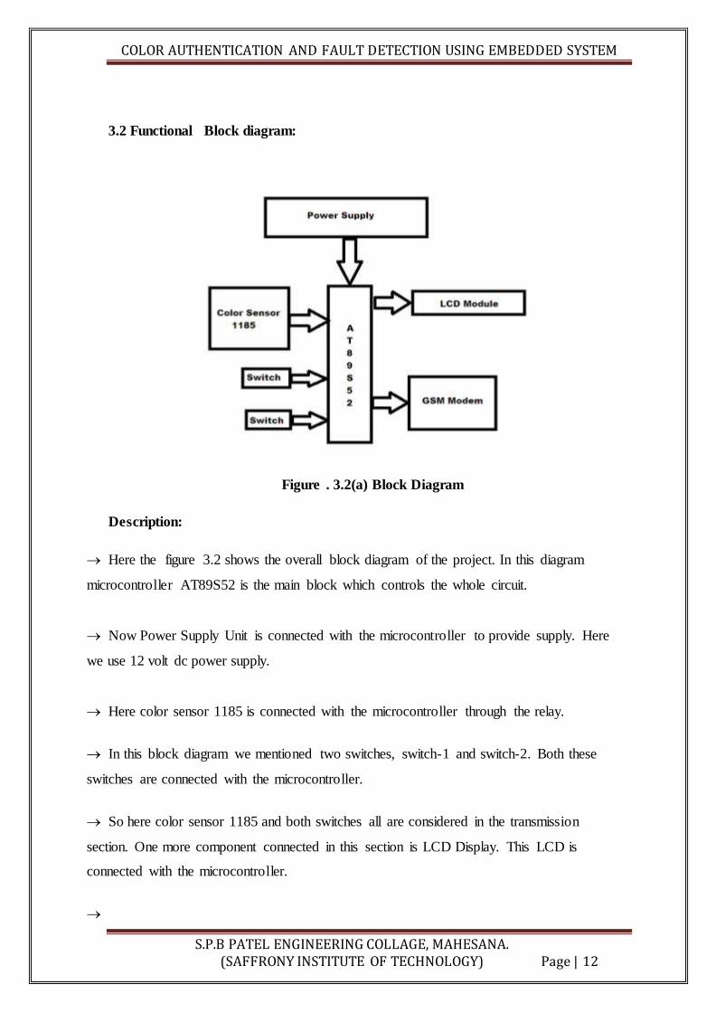
3.2 Functional Block diagram:
Figure . 3.2(a) Block Diagram
Description:
Here the figure 3.2 shows the overall block diagram of the project. In this diagram
microcontroller AT89S52 is the main block which controls the whole circuit.
Now Power Supply Unit is connected with the microcontroller to provide supply. Here
we use 12 volt dc power supply.
Here color sensor 1185 is connected with the microcontroller through the relay.
In this block diagram we mentioned two switches, switch-1 and switch-2. Both these
switches are connected with the microcontroller.
So here color sensor 1185 and both switches all are considered in the transmission
section. One more component connected in this section is LCD Display. This LCD is
connected with the microcontroller.
COLOR AUTHENTICATION AND FAULT DETECTION USING EMBEDDED SYSTEM
S.P.B PATEL ENGINEERING COLLAGE, MAHESANA. (SAFFRONY INSTITUTE OF TECHNOLOGY) Page | 13
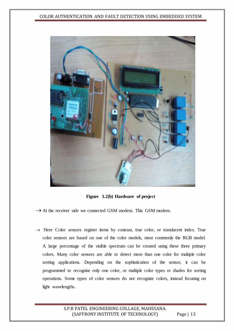
Figure 3.2(b) Hardware of project
At the receiver side we connected GSM modem. This GSM modem.
Here Color sensors register items by contrast, true color, or translucent index. True
color sensors are based on one of the color models, most commonly the RGB model.
A large percentage of the visible spectrum can be created using these three primary
colors. Many color sensors are able to detect more than one color for multiple color
sorting applications. Depending on the sophistication of the sensor, it can be
programmed to recognize only one color, or multiple color types or shades for sorting
operations. Some types of color sensors do not recognize colors, instead focusing on
light wavelengths.
COLOR AUTHENTICATION AND FAULT DETECTION USING EMBEDDED SYSTEM
S.P.B PATEL ENGINEERING COLLAGE, MAHESANA. (SAFFRONY INSTITUTE OF TECHNOLOGY) Page | 14
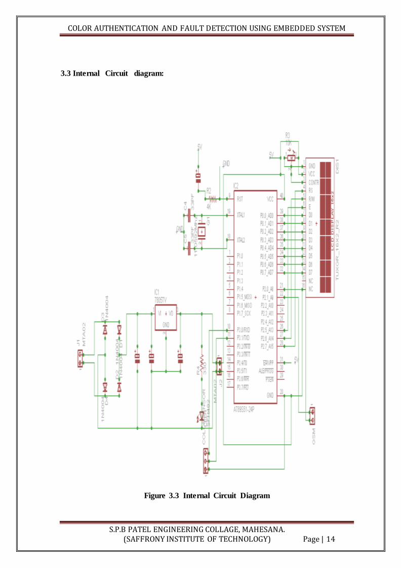
3.3 Internal Circuit diagram:
Figure 3.3 Internal Circuit Diagram
COLOR AUTHENTICATION AND FAULT DETECTION USING EMBEDDED SYSTEM
S.P.B PATEL ENGINEERING COLLAGE, MAHESANA. (SAFFRONY INSTITUTE OF TECHNOLOGY) Page | 15
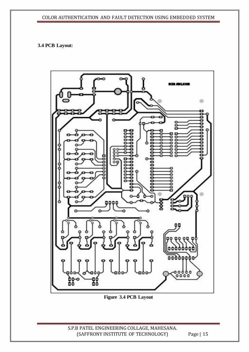
3.4 PCB Layout:
Figure 3.4 PCB Layout

COLOR AUTHENTICATION AND FAULT DETECTION USING EMBEDDED SYSTEM
S.P.B PATEL ENGINEERING COLLAGE, MAHESANA. (SAFFRONY INSTITUTE OF TECHNOLOGY) Page | 16
CHAPTER 4
FUNCTIONING
First, when we apply power supply to the hardware, one LED is turn on indicating
supply is available. As soon as we apply supply, the LCD display is turn on. It
displays R G B value of object detected by the color sensor. So at initial stage it
shows that LCD is connected with the microcontroller and the color sensor is
connected with the microcontroller via relay.
First we use the sample object which is detected by the color sensor 1185. After
that detection we press the switch-1 shown on the PCB board.
.
Figure 4(a) working of color sensor -1185

COLOR AUTHENTICATION AND FAULT DETECTION USING EMBEDDED SYSTEM
S.P.B PATEL ENGINEERING COLLAGE, MAHESANA. (SAFFRONY INSTITUTE OF TECHNOLOGY) Page | 17
This switch-1 stores that RGB value of that sample object as a temporary value
Now after the execution of the above step whenever another object is detected by
the color sensor we press switch-2..
Now Switch-2 will compare the current RGB value with the temporary saved
value.
Figure 4(b) Working of GSM Module
If the current value is match with that temporary value then controller will
transferred the information to the GSM modem.
After the matching of data GSM modem will send message that “valid color is
detected”. Otherwise it will send “valid color is not detected”. Now here one more
thing is remaining is that whenever the true color is detected LED-1 (TRUE) is
on. And when the false color is detected LED-2 (FALSE) is on.

COLOR AUTHENTICATION AND FAULT DETECTION USING EMBEDDED SYSTEM
S.P.B PATEL ENGINEERING COLLAGE, MAHESANA. (SAFFRONY INSTITUTE OF TECHNOLOGY) Page | 18
CHAPTER 5
PROJECT TESTING
When RED shade of color is detected you would get following type of data in
terminal
R=130 G=030 B=030 L=010
Here value of RED is 130 while Green and Blue are 30 both L=10 means the
amount of Light reflected by surface, White surface will reflect most and black
the least, This L value you can use to detect the darkness of surface.
We recently added this L parameter since it was difficult to detect white and black
surface from only RGB values.
The sample code of microcontroller and VB software does not implement L value
processing but it works with only RGB values. L value can be used to detect .

COLOR AUTHENTICATION AND FAULT DETECTION USING EMBEDDED SYSTEM
S.P.B PATEL ENGINEERING COLLAGE, MAHESANA. (SAFFRONY INSTITUTE OF TECHNOLOGY) Page | 19
Figure 5(a) Final Hardware (running)
Figure 5(b) Hex value
Each value will be from 0 to 255, Let us see each byte in detail
The output you get for a red surface would contain R value the most out of
RBG. It does not reflect the actual red value of surface.
If you multiply the R value with a constant (scaling factor) then match
with actual R value then you can get actual RGB values.
This can do easily with software provided in VB. Once you calculate the
actual RBG values by matching the color in VB with the surface color of
material.
You can use this multiplier value to scale the output to actual RBG values
of material

COLOR AUTHENTICATION AND FAULT DETECTION USING EMBEDDED SYSTEM
S.P.B PATEL ENGINEERING COLLAGE, MAHESANA. (SAFFRONY INSTITUTE OF TECHNOLOGY) Page | 20
CHAPTER 6
PROGRAMING
#include<stdio.h>
#include<reg51.h>
#include<string.h>
#include<Delay.h>
#include<UART.h>
#include<Functions.h>
#include<PinDefine.h>
#include<LCD.h>
void main()
{
unsigned char count = 0;
ALL_OFF();
delay(500);
init_uart();
lcd_init();
Update_Display(init_d);
delay(500);
// transmit_string("Uart Test OK\r\n");
Get_RGB_Value();
Update_RGB();

COLOR AUTHENTICATION AND FAULT DETECTION USING EMBEDDED SYSTEM
S.P.B PATEL ENGINEERING COLLAGE, MAHESANA. (SAFFRONY INSTITUTE OF TECHNOLOGY) Page | 21
while(1)
{
Get_RGB_Value();
Update_RGB();
// transmit_string("Uart Test OK\r\n");
if(SW2 == 0)
{
Get_RGB_Value();
if(R_Val > (RS_Val - RGB_Range) && R_Val
< (RS_Val + RGB_Range) &&
G_Val > (GS_Val - RGB_Range) && G_Val
< (GS_Val + RGB_Range) &&
B_Val > (BS_Val - RGB_Range) && B_Val <
(BS_Val + RGB_Range))
{
RLY3 = 1;
send_sms(True,user1_id);
delay(1000);
send_sms(True,user2_id);
delay(1000);
send_sms(True,user3_id);
RLY3 = 0;
}
else

COLOR AUTHENTICATION AND FAULT DETECTION USING EMBEDDED SYSTEM
S.P.B PATEL ENGINEERING COLLAGE, MAHESANA. (SAFFRONY INSTITUTE OF TECHNOLOGY) Page | 22
{
RLY4 = 1;
send_sms(False,user1_id);
delay(1000);
send_sms(False,user2_id);
delay(1000);
send_sms(False,user3_id);
RLY4 = 0;
}
Update_RGB();
}
if(SW1 == 0)
{
while(SW1 != 1);
Get_RGB_Value();
RS_Val = R_Val;
GS_Val = G_Val;
BS_Val = B_Val;
Update_RGB();
}
}
}

COLOR AUTHENTICATION AND FAULT DETECTION USING EMBEDDED SYSTEM
S.P.B PATEL ENGINEERING COLLAGE, MAHESANA. (SAFFRONY INSTITUTE OF TECHNOLOGY) Page | 23
CHAPTER 7
CONCLUSION
This project is not limited for any particular application, it can be used anywhere
in a process industries with little modifications in software coding according to the
requirements. This concept not only ensures that our work will be usable in the
future but also provides the flexibility to adapt and extend, as needs change.
In this project work we have studied and implemented a complete working model
using a microcontroller. This work includes the study of color sensor in many
applications.
COLOR AUTHENTICATION AND FAULT DETECTION USING EMBEDDED SYSTEM
S.P.B PATEL ENGINEERING COLLAGE, MAHESANA. (SAFFRONY INSTITUTE OF TECHNOLOGY) Page | 24
CHAPTER 8
FUTURE SCOPE
In this project we send message through GSM modem either color is valid or
invalid..
But we can expand this project in future and send the total valid or invalid product
detected in whole day using the counter.
In our project we connected our color sensor(1185) to micro controller with the
wires. This can be developed with wireless . This sensor will activate the micro
controller with the signals instead of using wires.

COLOR AUTHENTICATION AND FAULT DETECTION USING EMBEDDED SYSTEM
S.P.B PATEL ENGINEERING COLLAGE, MAHESANA. (SAFFRONY INSTITUTE OF TECHNOLOGY) Page | 25
CHAPTER 9
BIBLIOGRAPHY
www.electronics for u.com
www.electronicszone.com
8051 Microcontroller and Embedded Systems, by Muhammad Ali Mazidi,
www.IEEE Xplore.com
www.sunrom.com
www.engineersgarage.com/articles/gsm-gprs-modules
http://www.embedidea.com/led-interfacing-with-8051/
http://www.engineersgarage.com/microcontroller/8051projects/interface
http://www.electronics-lab.com/blog
Relay Systems, by I. T. Monseth and P. H. Robinson, McGraw-Hill Book Co.,
New York, 1935.
http://www.circuitstoday.com/working-of-relay
www.projectabstracts.com
www.zembedd.com
www.blogcircuit.edu.com
COLOR AUTHENTICATION AND FAULT DETECTION USING EMBEDDED SYSTEM
S.P.B PATEL ENGINEERING COLLAGE, MAHESANA. (SAFFRONY INSTITUTE OF TECHNOLOGY) Page | 26
ANNEXURE A: HARDWARE SECTION
Printed Circuit Board
Micro controller AT89S52
5V variable Dc Power Supply
Color Sensor 1185
GSM Module-900A
LCD Display
LED
RELAY(JQC-3FC(T73)DC12V)

COLOR AUTHENTICATION AND FAULT DETECTION USING EMBEDDED SYSTEM
S.P.B PATEL ENGINEERING COLLAGE, MAHESANA. (SAFFRONY INSTITUTE OF TECHNOLOGY) Page | 27
A.1 MICRO CONTROLLER
Introduction:
A microcontroller is an integrated chip that has processor, memory and several
other hardware units in it; these form the microcomputer part of the embedded
system.
Just as a microprocessor is the essential part of computing system, a
microcontroller is the most essential component of a control or communication
circuit.
Microcontrollers are particularly suited for use in embedded system for real time
control applications with on chip program memory and devices.
Figure A.1.1 Chip View (AT89S52)

COLOR AUTHENTICATION AND FAULT DETECTION USING EMBEDDED SYSTEM
S.P.B PATEL ENGINEERING COLLAGE, MAHESANA. (SAFFRONY INSTITUTE OF TECHNOLOGY) Page | 28
Block Diagram (AT89S52):
Figure A.1.2 Block Diagram (AT89S52)

COLOR AUTHENTICATION AND FAULT DETECTION USING EMBEDDED SYSTEM
S.P.B PATEL ENGINEERING COLLAGE, MAHESANA. (SAFFRONY INSTITUTE OF TECHNOLOGY) Page | 29
PIN Diagram (AT89S52):
Figure A.1.3 Pin Diagram of Micro controller

COLOR AUTHENTICATION AND FAULT DETECTION USING EMBEDDED SYSTEM
S.P.B PATEL ENGINEERING COLLAGE, MAHESANA. (SAFFRONY INSTITUTE OF TECHNOLOGY) Page | 30
PIN Description:
VCC: Supply voltage.
GND: Ground.
Figure A.1.4 Pin Description
Port 0 Port 0 is an 8-bit open drain bidirectional I/O port. As an output port, each pin can
sink eight TTL inputs. When 1s are written to port 0 pins, the pins can be used as high-
impedance inputs. Port 0 can also be configured to be the multiplexed low-order
address/data bus during accesses to external program and data memory. In this mode, P0
has internal pull-ups. Port 0 also receives the code bytes during Flash programming and
outputs the code bytes during program verification. External pull-ups are required
during program verification.

COLOR AUTHENTICATION AND FAULT DETECTION USING EMBEDDED SYSTEM
S.P.B PATEL ENGINEERING COLLAGE, MAHESANA. (SAFFRONY INSTITUTE OF TECHNOLOGY) Page | 31
PIN (1-8) Port 1: Port 1 is an 8-bit bidirectional I/O port with internal pull-ups. The Port
1 output buffers can sink/source four TTL inputs. When 1s are written to Port 1 pins, they
are pulled high by the internal pull-ups and can be used as inputs. As inputs, Port 1 pins
that are externally being pulled low will source current (IIL) because of the internal pull-
ups. In addition, P1.0 and P1.1 can be configured to be the timer/counter 2 external count
input (P1.0/T2) and the timer/counter 2 trigger input (P1.1/T2EX), respectively, as shown
in the following table. Port 1 also receives the low-order address bytes during Flash
programming and verification.
PIN (21-28) Port 2: Port 2 is an 8-bit bidirectional I/O port with internal pull-ups. The
Port 2 output buffers can sink/source four TTL inputs. When 1s are written to Port 2 pins,
they are pulled high by the internal pull-ups and can be used as inputs. As inputs, Port 2
pins that are externally being pulled low will source current (IIL) because of the internal
pull-ups. Port 2 emits the high-order address byte during fetches from external program
memory and during accesses to external data memory that uses 16-bit addresses (MOVX
@ DPTR). In this application, Port 2 uses strong internal pull-ups when emitting 1s.
During accesses to external data memory that uses 8-bit addresses (MOVX @ RI), Port 2
emits the contents of the P2 Special Function Register. Port 2 also receives the high-order
address bits and some control signals during Flash programming and verification. Port
Pin Alternate Functions P1.0 T2 (external count input to Timer/Counter 2), clock-out
P1.1 T2EX (Timer/Counter 2 capture/reload trigger and direction control) P1.5 MOSI
(used for In-System Programming) P1.6 MISO (used for In-System Programming) P1.7
SCK (used for In-System Programming)
PIN (10-17) Port 3: Port 3 is an 8-bit bidirectional I/O port with internal pull-ups. The
Port 3 output buffers can sink/source four TTL inputs. When 1s are written to Port 3 pins,
they are pulled high by the internal pull-ups and can be used as inputs. As inputs, Port 3
pins that are externally being pulled low will source current (IIL) because of the pull-ups.
Port 3 receives some control signals for Flash programming and verification. Port 3 also
serves the functions of various special features of the AT89S52, as shown in the fol-
lowing table.

COLOR AUTHENTICATION AND FAULT DETECTION USING EMBEDDED SYSTEM
S.P.B PATEL ENGINEERING COLLAGE, MAHESANA. (SAFFRONY INSTITUTE OF TECHNOLOGY) Page | 32
(PIN 9)RST: Reset irnput. A high on this pin for two machine cycles while the oscillator
is running resets the device. This pin drives high for 98 oscillator periods after the
Watchdog times out. The DISRTO bit in SFR AUXR (address 8EH) can be used to
disable this feature. In the default state of bit DISRTO, the RESET HIGH out feature is
enabled.
(PIN 30)ALE/PROG: Address Latch Enable (ALE) is an output pulse for latching the
low byte of the address during accesses to external memory. This pin is also the program
pulse input (PROG) during Flash programming. In normal operation, ALE is emitted at a
constant rate of 1/6 the oscillator frequency and may be used for external timing or
clocking purposes. Note, however, that one ALE pulse is skipped during each access to
external data memory. If desired, ALE operation can be disabled by setting bit 0 of SFR
location 8EH. With the bit set, ALE is active only during a MOVX or MOVC instruction.
Otherwise, the pin is weakly pulled high. Setting the ALE-disable bit has no effect if the
microcontroller is in external execution mode.
(PIN 29)PSEN: Program Store Enable (PSEN) is the read strobe to external program
memory. When the AT89S52 is executing code from external program memory, PSEN is
activated twice each machine cycle, except that two PSEN activations are skipped during
each access to external data memory.

COLOR AUTHENTICATION AND FAULT DETECTION USING EMBEDDED SYSTEM
S.P.B PATEL ENGINEERING COLLAGE, MAHESANA. (SAFFRONY INSTITUTE OF TECHNOLOGY) Page | 33
(PIN 31)EA/VPP: External Access Enable. EA must be strapped to GND in order to
enable the device to fetch code from external program memory locations starting at
0000H up to FFFFH. Note, however, that if lock bit 1 is programmed, EA will be
internally latched on reset. EA should be strapped to VCC for internal program
executions. This pin also receives the 12-volt programming enable voltage (VPP) during
Flash programming.
(PIN 18)XTAL1: Input to the inverting oscillator amplifier and input to the internal clock
operating circuit.
(PIN 19) XTAL2: Output from the inverting oscillator amplifier.
Special Function Registers: A map of the on-chip memory area called the Special
Function Register (SFR) space is shown in Table 5-1. Note that not all of the addresses
are occupied, and unoccupied addresses may not be implemented on the chip. Read
accesses to these addresses will in general return random data, and write accesses will
have an indeterminate effect. User software should not write 1s to these unlisted
locations, since they may be used in future products to invoke new features. In that case,
the reset or inactive values of the new bits will always be 0.
Timer 2 Registers: Control and status bits are contained in registers T2CON (shown in
Table 5- 2) and T2MOD (shown in Table 10-2) for Timer 2. The register pair (RCAP2H,
RCAP2L) are the Capture/Reload registers for Timer 2 in 16-bit capture mode or 16-bit
auto-reload mode.
Interrupt Registers: The individual interrupt enable bits are in the IE register. Two
priorities can be set for each of the six interrupt sources in the IP register.

COLOR AUTHENTICATION AND FAULT DETECTION USING EMBEDDED SYSTEM
S.P.B PATEL ENGINEERING COLLAGE, MAHESANA. (SAFFRONY INSTITUTE OF TECHNOLOGY) Page | 34
Features:
8-bit CPU
8K bytes of flash
256 bytes of RAM
32 I/O lines
Two data pointers
Three 16bit timer/counters
Full duplex serial port
Application:
Automotive
Building Automation
Industrial Automation
Lighting
Mobile Electronics
PC Peripherals

COLOR AUTHENTICATION AND FAULT DETECTION USING EMBEDDED SYSTEM
S.P.B PATEL ENGINEERING COLLAGE, MAHESANA. (SAFFRONY INSTITUTE OF TECHNOLOGY) Page | 35
A.2 COLOR SENSOR-1185
Figure A.2.1.Color Sensor -1185(Top view)
This color sensor identifies color and gives serial output of RBG value. It can
identify 16.7 million color shades giving RGB value for the detected color. The detected
color is identified as amount of three primary color values namely Red, Green & Blue
with 8 bit accuracy for each primary color. Any color can be separated or combined into
three primary colors Red, Green and Blue using the RBG values
f
Figure A.2.2 Color Sensor -1185(Back view)

COLOR AUTHENTICATION AND FAULT DETECTION USING EMBEDDED SYSTEM
S.P.B PATEL ENGINEERING COLLAGE, MAHESANA. (SAFFRONY INSTITUTE OF TECHNOLOGY) Page | 36
Figure A.2.3 interfacing diagram of color sensor
COLOR AUTHENTICATION AND FAULT DETECTION USING EMBEDDED SYSTEM
S.P.B PATEL ENGINEERING COLLAGE, MAHESANA. (SAFFRONY INSTITUTE OF TECHNOLOGY) Page | 37
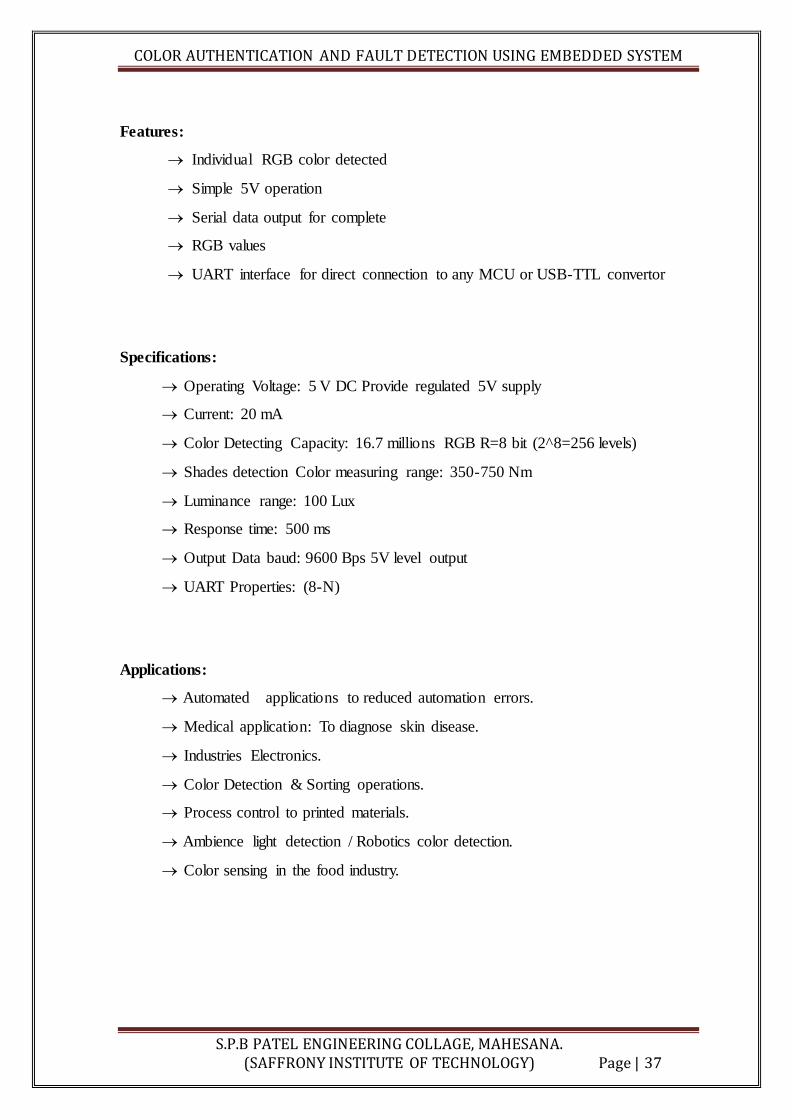
Features:
Individual RGB color detected
Simple 5V operation
Serial data output for complete
RGB values
UART interface for direct connection to any MCU or USB-TTL convertor
Specifications:
Operating Voltage: 5 V DC Provide regulated 5V supply
Current: 20 mA
Color Detecting Capacity: 16.7 millions RGB R=8 bit (2^8=256 levels)
Shades detection Color measuring range: 350-750 Nm
Luminance range: 100 Lux
Response time: 500 ms
Output Data baud: 9600 Bps 5V level output
UART Properties: (8-N)
Applications:
Automated applications to reduced automation errors.
Medical application: To diagnose skin disease.
Industries Electronics.
Color Detection & Sorting operations.
Process control to printed materials.
Ambience light detection / Robotics color detection.
Color sensing in the food industry.
COLOR AUTHENTICATION AND FAULT DETECTION USING EMBEDDED SYSTEM
S.P.B PATEL ENGINEERING COLLAGE, MAHESANA. (SAFFRONY INSTITUTE OF TECHNOLOGY) Page | 38
A.3 GSM MODULE (SIM900A)
Introduction:
Global system for mobile communication (GSM) is a globally accepted standard for
digital cellular communication. GSM is the name of a standardization group established
in 1982 to create a common European mobile telephone standard that would formulate
specifications for a pan-European mobile cellular radio system operating at 900 MHz It is
estimated that many countries outside of Europe will join the GSM partnership.
Specifications:
Mobile Frequency Range : Rx: 925-960;Tx: 880-915
Multiple Access Method : TDMA/FDM
Duplex Method : FDD
Number of Channels1 : 24 (8 users per channel)
Channel Spacing : 200 kHz
Modulation: GMSK (0.3 Gaussian Filter)
Channel Bit Rate : 270.833Kb
GSM Frequency Bands:
The initial design used the 900 MHz range.
Uplink to BTS 890 - 915 MHz
Downlink to MS 935 - 960 MHz
There are 124 channels of 200 kHz and 100 kHz of guard spectrum at the edges of
the band - and each channel can carry 8 TDMA users.
Usually an operator does not have access to the full range.
GSM technology is also used on other frequencies 4500, 800, 1800, 1900 MHz

COLOR AUTHENTICATION AND FAULT DETECTION USING EMBEDDED SYSTEM
S.P.B PATEL ENGINEERING COLLAGE, MAHESANA. (SAFFRONY INSTITUTE OF TECHNOLOGY) Page | 39
GSM Data Services:
The basic GSM data service transmits data instead of voice, using a time slot like
a voice call.
9.6 or 14.4 kbps rate
Time based billing
The data connection from the MS is usually connected to an traditional analog
modem, which is connected to the PSTN.
The operator can also provide direct data connections.
Long setup time 5-30 seconds.
High Speed Circuit Switched Data (HSCSD) uses multiple time slots to increase
the data rate.
Up to 57.6 kbps
GSM data appears to be an evolutionary dead end and packet based data
transmission is going to Overtake it.
Figure A.3.1 GSM Module (Hardware)
COLOR AUTHENTICATION AND FAULT DETECTION USING EMBEDDED SYSTEM
S.P.B PATEL ENGINEERING COLLAGE, MAHESANA. (SAFFRONY INSTITUTE OF TECHNOLOGY) Page | 40
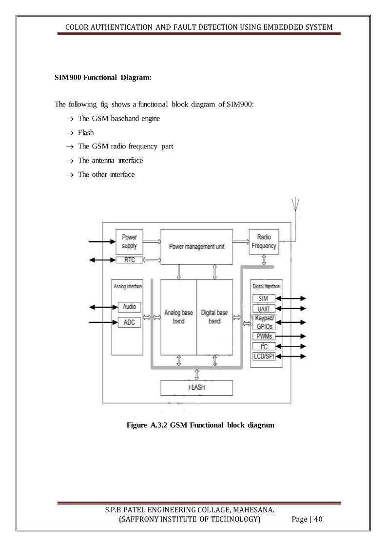
SIM900 Functional Diagram:
The following fig shows a functional block diagram of SIM900:
The GSM baseband engine
Flash
The GSM radio frequency part
The antenna interface
The other interface
Figure A.3.2 GSM Functional block diagram
COLOR AUTHENTICATION AND FAULT DETECTION USING EMBEDDED SYSTEM
S.P.B PATEL ENGINEERING COLLAGE, MAHESANA. (SAFFRONY INSTITUTE OF TECHNOLOGY) Page | 41
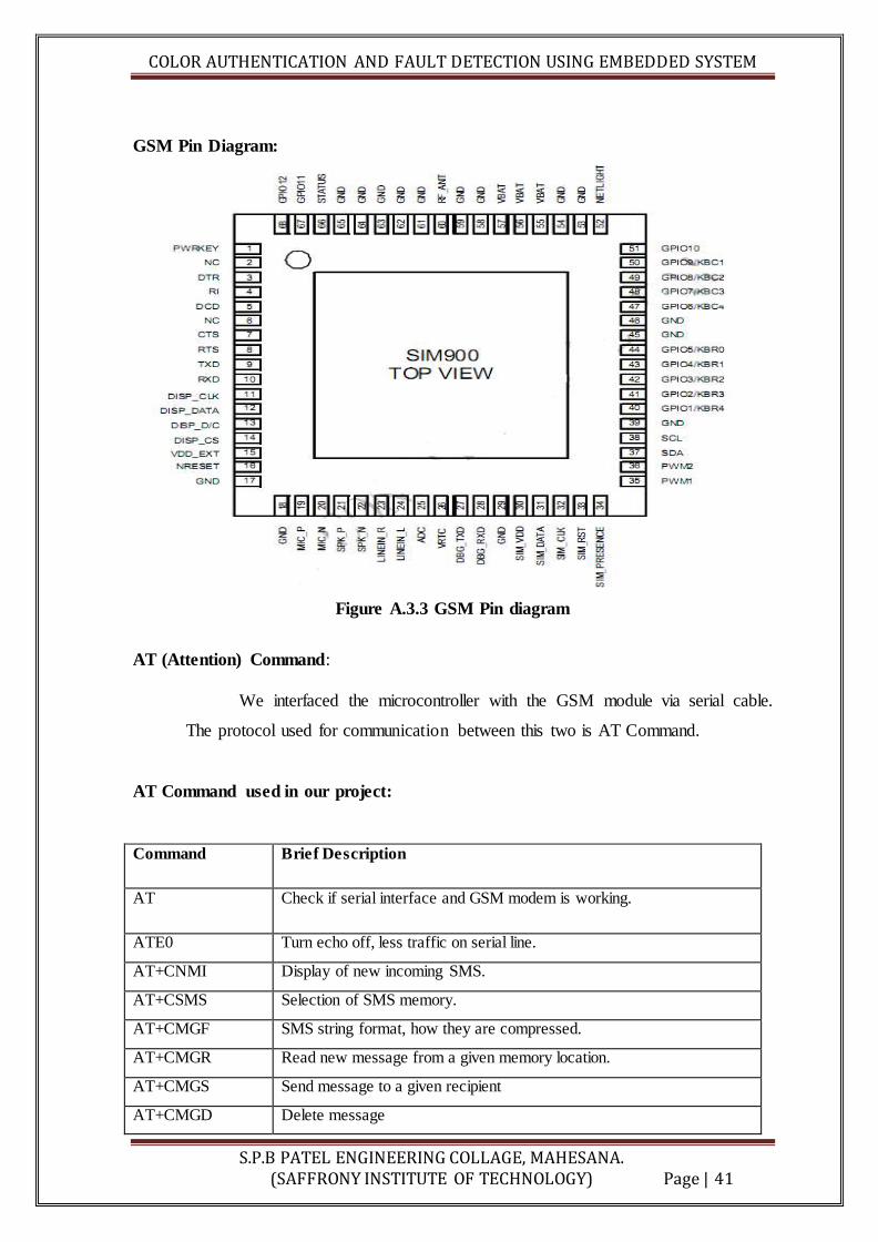
GSM Pin Diagram:
Figure A.3.3 GSM Pin diagram
AT (Attention) Command:
We interfaced the microcontroller with the GSM module via serial cable.
The protocol used for communication between this two is AT Command.
AT Command used in our project:
Command Brief Description
AT Check if serial interface and GSM modem is working.
ATE0 Turn echo off, less traffic on serial line.
AT+CNMI Display of new incoming SMS.
AT+CSMS Selection of SMS memory.
AT+CMGF SMS string format, how they are compressed.
AT+CMGR Read new message from a given memory location.
AT+CMGS Send message to a given recipient
AT+CMGD Delete message
COLOR AUTHENTICATION AND FAULT DETECTION USING EMBEDDED SYSTEM
S.P.B PATEL ENGINEERING COLLAGE, MAHESANA. (SAFFRONY INSTITUTE OF TECHNOLOGY) Page | 42
Application of GSM module:
Any mobile to mobile or telemetry operations
SMS/Call/GPRS function with any microcontroller and PC
Data logging, SMS/Call alerts, Remote Monitoring & GPRS applications.
Sequence of sending MSG:
First select the text mode for SMS by sending the following AT command to
GSM modem AT+CMGF=1. This command configures the GSM modem in text
mode.
Send the following AT Command for sending SMS message in text mode along
with mobile number to the GSM Modem : AT+CMGS =+mobile no . This
command sends the mobile number of the recipient mobile to the GSM modem.
Send the text message string ("hello!") to the GSM Modem This is a test message
from UART.
Send ASCII code for CTRL+Z i.e., 0x1A to GSM Modem to transmit the message
to mobile phone. After message string has been sent to the modem, send CTRL+Z
to the micro-controller, which is equivalent to 0x1A (ASCII value) Every AT
command is followed by i.e. carriage return and line feed

COLOR AUTHENTICATION AND FAULT DETECTION USING EMBEDDED SYSTEM
S.P.B PATEL ENGINEERING COLLAGE, MAHESANA. (SAFFRONY INSTITUTE OF TECHNOLOGY) Page | 43
A.4 LCD DISPLAY
Introduction:
A liquid crystal is a material (normally organic for LCD’s) that will flow like a liquid but
whose molecular structure has some properties normally associated with solids. The
Liquid Crystal Display (LCD) is a low power device. The power requirement is typically
in the order of microwatts for the LCD. However, an LCD requires an external or internal
light source. We are making use of LCD in our project to display the PIR mode and room
temperature.
LCD is a type of display used in digital watches and many portable computers. LCD
displays utilize to sheets of polarizing material with a liquid crystal solution between
them. An electric current passed through the liquid causes the crystals to align so that
light cannot pass through them. LCD technology has advanced very rapidly since its
initial inception over a decade ago for use in lap top computers. Technical achievements
has resulted in brighter displace, higher resolutions, reduce response times and cheaper
manufacturing process.
The liquid crystals can be manipulated through an applied electric voltage so that light is
allowed to pass or is blocked. By carefully controlling where and what wavelength
(colour) of light is allowed to pass, the LCD monitor is able to display images. A
backlight provides LCD monitor’s brightness.
Over the years many improvements have been made to LCD to help enhance resolution,
image, sharpness and response times.
One of the latest such advancement is applied to glass during acts as switch allowing
control of light at the pixel level, greatly improving LCD’s ability to display small-sized
fonts and image clearly.
COLOR AUTHENTICATION AND FAULT DETECTION USING EMBEDDED SYSTEM
S.P.B PATEL ENGINEERING COLLAGE, MAHESANA. (SAFFRONY INSTITUTE OF TECHNOLOGY) Page | 44
Other advances have allowed LCD’s to greatly reduce liquid crystal cell response times.
Response time is basically the amount of time it takes for a pixel to “change colors”, in
reality response time is the amount of time it takes a liquid crystal cell to go from being
active to inactive.
This is due to following reasons:
The declining prices of LCDs.
The ability to display numbers, characters and graphics. This is in contrast to
LEDs, which are limited to numbers and a few characters.
An intelligent LCD display of two lines, 20 characters per line that is interfaced to
the pic16f72 microcontroller.
Incorporation of a refreshing controller into the LCD, thereby relieving the CPU to keep
displaying the data. Ease of programming for characters and graphics.
Most of the LCD modules conform to a standard interface specification. A 14-pin access
is provided having eight data lines, three control lines and three power lines. The
connections are laid out in one of the two common configurations, either two rows of
seven pins, or a single row of 14 pins.
One of these pins is numbered on the LCD’s printed circuit board (PCB), but if not, it is
quite easy to locate pin1. Since this pin is connected to ground, it often has a thicker PCB
track, connected to it, and it is generally connected to metal work at same point.

COLOR AUTHENTICATION AND FAULT DETECTION USING EMBEDDED SYSTEM
S.P.B PATEL ENGINEERING COLLAGE, MAHESANA. (SAFFRONY INSTITUTE OF TECHNOLOGY) Page | 45
Pin Diagram:
Most of the LCD modules conform to a standard interface specification. A 14pin access is
provided having eight data lines, three control lines and three power lines. The connections
are laid out in one of the two common configurations, either two rows of seven pins, or a
single row of 14 pins.
Figure A.4.1 Pin diagram of LCD display
Pin Description:
Vcc, Vss, VEE:
While Vcc and Vss provide +5v and ground, respectively, VEE is used for controlling
LCD contrast.

COLOR AUTHENTICATION AND FAULT DETECTION USING EMBEDDED SYSTEM
S.P.B PATEL ENGINEERING COLLAGE, MAHESANA. (SAFFRONY INSTITUTE OF TECHNOLOGY) Page | 46
RS (Register Select):
There are two very important registers inside the LCD. The RS pin is used for their
selection as follows. If RS = 0, the instruction command code register is selected,
allowing the user to send as command code register is selected, allowing the user to send
a command such as clear display, cursor at home, etc.
If RS = 1 the data register is selected, allowing the user to send data to be displayed on the
LCD.
R/W (Read/Write):
R/W input allows the user to write information to the LCD or read information from it.
R/W = 1 when reading; R/W = 0 when writing.
En (Enable):
The enable pin is used by the LCD to latch information presented to its data pins. When
data is supplied to data pins, a high -to -low pulse must be applied to this pin in order
for the LCD latch in the data pins. This pulse must be a minimum of 450 ns wide.
D0 -D7:
The 8 -bit data pins, D0 -D7, are used to send information to the LCD or read the contents
of the LCD's internal registers. To display letters and numbers, we send ASCII codes for
the letters A-Z, a-z, and numbers 0-9 to these pins while making RS=1.There are also
instruction command codes that can be sent to the LCD to clear the display or force the
cursor to the home position or blink the instruction command codes. We also use RS=0 to
Check the busy flag bit to see if the LCD is ready to receive information. The busy flag is
D7 and can be read when R/W=1 and RS=0, as follows: if R/W=1, RS=0. When D7=1
(busy flag=1), the LCD is busy taking care of internal operations and will not accept any
information.

COLOR AUTHENTICATION AND FAULT DETECTION USING EMBEDDED SYSTEM
S.P.B PATEL ENGINEERING COLLAGE, MAHESANA. (SAFFRONY INSTITUTE OF TECHNOLOGY) Page | 47
Handling the EN Control Line:
As mentioned above, the EN line is used to tell the LCD that it is ready to execute an
instruction that prepared on the data bus and on the other control lines. Note that the EN
line must be raised/lowered before/after each instruction sent to the LCD regardless of
whether that instruction is read or write text or instruction. In short, someone must always
manipulate EN when communicating with the LCD. EN is the LCD's way of knowing
Figure A.4.2 Pin Connection of LCD display
Checking the Busy Status of the LCD:
As previously mentioned, it takes a certain amount of time for each instruction to be
executed by the LCD. The delay varies depending on the frequency of the crystal attached
to the oscillator input of the controller as well as the instruction which is being executed.
While it is possible to write code that waits for a specific amount of time to allow the
LCD to execute instructions, this method of "waiting" is not very flexible.
A more robust method of programming is to use the "Get LCD Status" command to
determine whether the LCD is still busy executing the last instruction received. The "Get
LCD Status" command will return to the user two bits of information; the information that
is useful to the user right now is found in DB7. In summary, when user issue the "Get
LCD Status" command the LCD will immediately raise DB7 if it's still busy executing a
command or lower DB7 to indicate that the LCD is no longer occupied.

COLOR AUTHENTICATION AND FAULT DETECTION USING EMBEDDED SYSTEM
S.P.B PATEL ENGINEERING COLLAGE, MAHESANA. (SAFFRONY INSTITUTE OF TECHNOLOGY) Page | 48
Thus the program can query the LCD until DB7goes low, indicating the LCD is no longer
busy. At that point user is free to continue and send the next command.
Initializing the LCD:
LCD must be initialized and configured before using. This is accomplished by sending a
number of initialization instructions to the LCD. The first instruction send must tell the
LCD whether it is to be communicated with an 8-bit or 4-bit data bus. 5x8 dot character
font should also be selected. These two options are selected by sending the command 38h
to the LCD as a command.
a) Clearing the Display :
When the LCD is first initialized, the screen should automatically be cleared by the
controller.
b) Writing Text into the LCD :
The data to be displayed is send to the LCD through data bus.
c) Cursor Positioning :
The cursor positioning in a LCD can be done in the right entry mode or left entry mode.
As left entry mode is flexible it is implemented.
Basic Commands of LCD:
Set Cursor Move Direction:
06h –Shift cursor to the right
80h –force cursor to the beginning of the first line
C0h –force cursor to the beginning of second line
02h –return home
04h –Shift cursor to the left

COLOR AUTHENTICATION AND FAULT DETECTION USING EMBEDDED SYSTEM
S.P.B PATEL ENGINEERING COLLAGE, MAHESANA. (SAFFRONY INSTITUTE OF TECHNOLOGY) Page | 49
Enable Display/Cursor:
0Ch -Turn Display On, cursor off
0ah -Turn Cursor On, Display off
08h -Cursor off, Display off
0eh/0fh-display on, cursor blinking
Shift Display:
18h –1Ch -Display Shift to left, right respectively
Set Interface Length:
38h –Initialize LCD as 2 lines, 5*7 matrixes.
Reading Data back is used in this application, which requires data to be moved
back and forth on the LCD. The "Busy Flag" is polled to determine whether the
last instruction that has been sent has completed processing. Before we send
commands or data to the LCD module, the Module must be initialized. For eight
bit mode, this is done using the following series of operations:
Wait more than 15 msecs after power is applied.
Write 0x030 to LCD and wait 5 msecs for the instruction to complete
Write 0x030 to LCD and wait 160 µsecs for instruction to complete
Write 0x030 AGAIN to LCD and wait 160 µsecs or Poll the Busy Flag
Set the Operating Characteristics of the LCD
Write "Set Interface Length"
Write 0x001 to Clear the Display
Write "Set Cursor Move Direction" Setting Cursor Behavior Bits

COLOR AUTHENTICATION AND FAULT DETECTION USING EMBEDDED SYSTEM
S.P.B PATEL ENGINEERING COLLAGE, MAHESANA. (SAFFRONY INSTITUTE OF TECHNOLOGY) Page | 50
When LCD is powered up, the display should show a series of dark squares,
possibly only on part of display. These characters are actually in their off state, so
the contrast control should be adjusted anti-clockwise until the squares are just
visible. The display module resets itself to an initial state when power is applied,
which curiously the display has blanked off so that even if characters are entered,
they cannot be seen. It is therefore necessary to issue a command at this point, to
switch the display on.
Figure A.4.3 Interfacing 16x2 LCD Module

COLOR AUTHENTICATION AND FAULT DETECTION USING EMBEDDED SYSTEM
S.P.B PATEL ENGINEERING COLLAGE, MAHESANA. (SAFFRONY INSTITUTE OF TECHNOLOGY) Page | 51
A.5 LED
Introduction:
LED stands for Light Emitting Diode. In short it is a small tube which glows when
energized. Unlike the incandescent light bulb, LED's have no filament to burn out
resulting in much longer life. They also produce the same amount of light with
approximately 10% of the electricity making them much less expensive to operate.
Basically, LEDs are just tiny light bulbs that fit easily into an electrical circuit. But unlike
ordinary incandescent bulbs, they don't have a filament that will burn out, and they don't
get especially hot. They are illuminated solely by the movement of electrons in a
semiconductor material, and they last just as long as a standard transistor.
Figure A.5.1 LED Construction
COLOR AUTHENTICATION AND FAULT DETECTION USING EMBEDDED SYSTEM
S.P.B PATEL ENGINEERING COLLAGE, MAHESANA. (SAFFRONY INSTITUTE OF TECHNOLOGY) Page | 52
A light-emitting diode (LED) is an electronic light source. LEDs are based on the
semiconductor diode.
When the diode is forward biased (switched on), electrons are able to recombine
with holes and energy is released in the form of light. This effect is called
electroluminescence and the color of the light is determined by the energy gap of
the semiconductor.
The LED is usually small in area (less than 1 mm2) with integrated optical
components to shape its radiation pattern and assist in reflection.
LEDs present many advantages over traditional light sources including lower
energy consumption, longer lifetime, improved robustness, smaller size and faster
switching.
One of the key advantages of LED-based lighting is its high efficiency, as
measured by its light output per unit power input. White LEDs quickly matched
and overtook the efficiency of standard incandescent lighting systems.
LEDs employ "cold" light, which means that most of the energy delivered is in the
visible spectrum. LEDs waste little energy in the form of heat. In comparison,
most of the energy in an incandescent light source is in the infrared (non-visible)
portion of the spectrum that results in a lot of heat.
Currently, white LEDs are achieved in one of the following three methods:
Red, Blue, Green (RGB) LED color mixing;
Coating a Blue LED with Phosphor (typically Yttrium Aluminum Garnet – YAG)
so that when energized photons strike the coating it will emit a mixture of
wavelengths to produce a white color;
Coating an Ultra Violet (UV) LED with Phosphor;
COLOR AUTHENTICATION AND FAULT DETECTION USING EMBEDDED SYSTEM
S.P.B PATEL ENGINEERING COLLAGE, MAHESANA. (SAFFRONY INSTITUTE OF TECHNOLOGY) Page | 53
A.6 RELAY
Introduction:
What is a relay?
We know that most of the high end industrial application devices have relays for their
effective working. Relays are simple switches which are operated both electrically and
mechanically. Relays consist of a n electromagnet and also a set of contacts. The
switching mechanism is carried out with the help of the electromagnet. There are also
other operating principles for its working. But they differ according to their applications.
Most of the devices have the application of relays.
Figure A.6.1 RELAY (JQC-3FC(T73)DC12V)

COLOR AUTHENTICATION AND FAULT DETECTION USING EMBEDDED SYSTEM
S.P.B PATEL ENGINEERING COLLAGE, MAHESANA. (SAFFRONY INSTITUTE OF TECHNOLOGY) Page | 54
Why is a relay used?
The main operation of a relay comes in places where only a low-power signal can be used
to control a circuit. It is also used in places where only one signal can be used to control a
lot of circuits. The application of relays started during the invention of telephones. They
played an important role in switching calls in telephone exchanges. They were also used
in long distance telegraphy. They were used to switch the signal coming from one source
to another destination. After the invention of computers they were also used to perform
Boolean and other logical operations. The high end applications of relays require high
power to be driven by electric motors and so on. Such relays are called contactors.
How to test a relay:
A relay will usually have a coil, pole terminal and a set of contacts. The set of contacts
that are open when the relay is not energized are called normally open (N/O) contacts and
the set of contacts that are closed when the relay is not energized are called normally
closed (N/C) contacts. The following steps can be used to perform the testing of the relay
using a multimeter.
Keep the multimeter in the continuity check mode.
Check for continuity between the N/C contacts and pole.
Check for discontinuity between N/O contacts and the pole.
Now energies the relay using the rated voltage. For example use a 9V battery for
energizing a 9V relay. The relay will engage with clicking sound.
Now check for continuity between N/O contacts and pole.
Also check for discontinuity between N/C contacts and pole.
As a final test, measure the resistance of the relay coil using a multimeter and
check whether it is matching to the value stated by the manufacturer.
COLOR AUTHENTICATION AND FAULT DETECTION USING EMBEDDED SYSTEM
S.P.B PATEL ENGINEERING COLLAGE, MAHESANA. (SAFFRONY INSTITUTE OF TECHNOLOGY) Page | 55
ANNEXURE B: LAYOUT
We design our PCB layout by using EGALE layout designing software.
So let’s take overview of this software:
First open a new project in the Control Panel window using the pull-down
menus on the top toolbar as shown to the right. Create a unique project name
that starts with your last name.
2. Next create a new schematic in your project folder using similar pull down
menus (File, New, and Schematic). An empty schematic window will appear,
waiting for you to create your circuit diagram using components from the
library. Before moving on, make sure to save your work (File, Save All). Be
sure to save your work every 10 minutes or so.

COLOR AUTHENTICATION AND FAULT DETECTION USING EMBEDDED SYSTEM
S.P.B PATEL ENGINEERING COLLAGE, MAHESANA. (SAFFRONY INSTITUTE OF TECHNOLOGY) Page | 56
Add nets to schematic:
Use the Draw->Net command to connect components
Step 2a Add supply connectors to the schematic
Step 2b add I/O pads and test points to the layout
Step 3: Electrical Rule Check (Tools->ERC)
COLOR AUTHENTICATION AND FAULT DETECTION USING EMBEDDED SYSTEM
S.P.B PATEL ENGINEERING COLLAGE, MAHESANA. (SAFFRONY INSTITUTE OF TECHNOLOGY) Page | 57
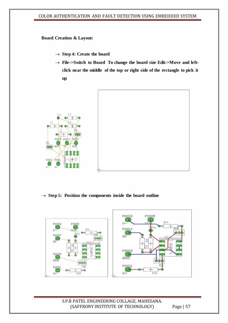
Board Creation & Layout:
Step 4: Create the board
File->Switch to Board To change the board size Edit->Move and left-
click near the middle of the top or right side of the rectangle to pick it
up
Step 5: Position the components inside the board outline

COLOR AUTHENTICATION AND FAULT DETECTION USING EMBEDDED SYSTEM
S.P.B PATEL ENGINEERING COLLAGE, MAHESANA. (SAFFRONY INSTITUTE OF TECHNOLOGY) Page | 58
Step 6: Route the tracks Tools->Auto...
Design Rule Check:
Step 7: Tools->DRC
This command will bring up a window showing the currently loaded
set of design rules
Click Check and this will run the design rules and say whether there
are any errors. If there are errors Tools->Errors will display them.
You must correct all DRU errors
Step 8: Pour Copper
a) white layout background
b) colored layout background
COLOR AUTHENTICATION AND FAULT DETECTION USING EMBEDDED SYSTEM
S.P.B PATEL ENGINEERING COLLAGE, MAHESANA. (SAFFRONY INSTITUTE OF TECHNOLOGY) Page | 59
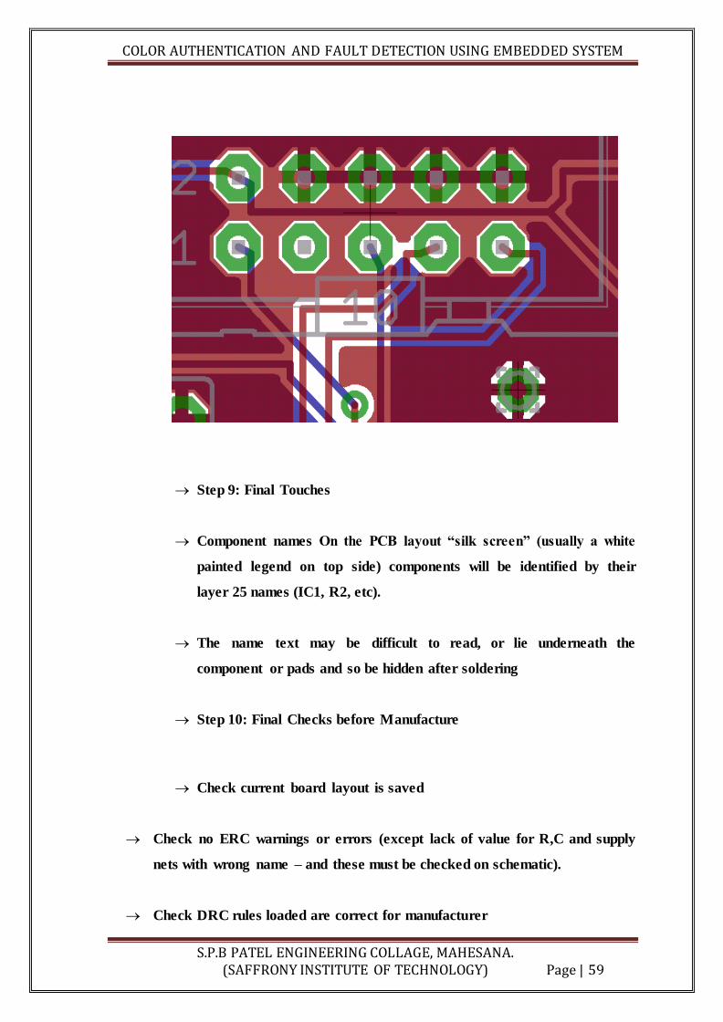
Step 9: Final Touches
Component names On the PCB layout “silk screen” (usually a white
painted legend on top side) components will be identified by their
layer 25 names (IC1, R2, etc).
The name text may be difficult to read, or lie underneath the
component or pads and so be hidden after soldering
Step 10: Final Checks before Manufacture
Check current board layout is saved
Check no ERC warnings or errors (except lack of value for R,C and supply
nets with wrong name – and these must be checked on schematic).
Check DRC rules loaded are correct for manufacturer
COLOR AUTHENTICATION AND FAULT DETECTION USING EMBEDDED SYSTEM
S.P.B PATEL ENGINEERING COLLAGE, MAHESANA. (SAFFRONY INSTITUTE OF TECHNOLOGY) Page | 60
Check board size is rectangular and has precisely the specified X,Y
dimensions using run-> statistic_brd. Boards with incorrect dimensions will
be rejected
Check auto command gives 100% routing without polygons falling apart
(message at bottom of window after auto command).
Check there are no DRC errors
Check component names (layer 25) are all visible, on board, not overlapping
pads, and if possible not hidden under components. Note that component
values (layer 27) are not printed on silk screen. (Board will be OK if you do
not do this but less easy to build)
Check that no object (track or pad) lies within 2mm of the board edge
Check you have included, easily visible, a layer 21 caption giving your lab
group
Your .brd file now contains all the information necessary to manufacture the
PCB, however make sure you keep safe both this and the schematic – you will
be able to print schematics, layouts, component value lists etc for use in
debugging
COLOR AUTHENTICATION AND FAULT DETECTION USING EMBEDDED SYSTEM
S.P.B PATEL ENGINEERING COLLAGE, MAHESANA. (SAFFRONY INSTITUTE OF TECHNOLOGY) Page | 61
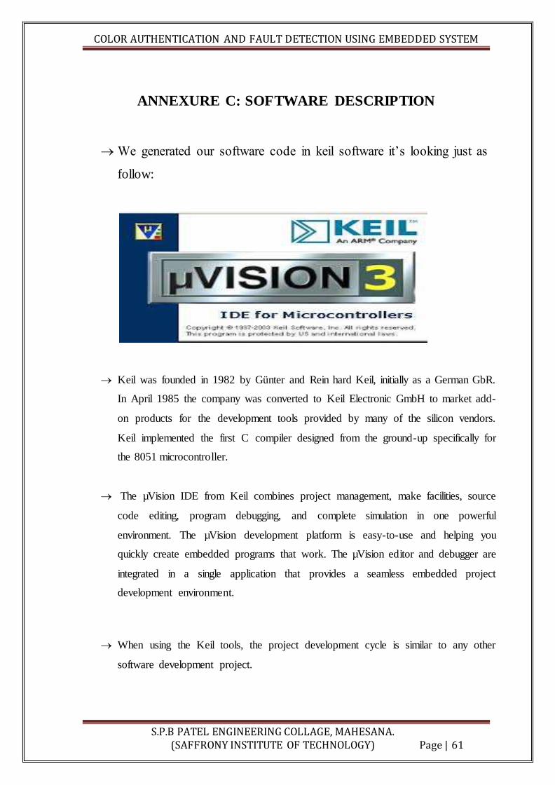
ANNEXURE C: SOFTWARE DESCRIPTION
We generated our software code in keil software it’s looking just as
follow:
Keil was founded in 1982 by Günter and Rein hard Keil, initially as a German GbR.
In April 1985 the company was converted to Keil Electronic GmbH to market add-
on products for the development tools provided by many of the silicon vendors.
Keil implemented the first C compiler designed from the ground-up specifically for
the 8051 microcontroller.
The µVision IDE from Keil combines project management, make facilities, source
code editing, program debugging, and complete simulation in one powerful
environment. The µVision development platform is easy-to-use and helping you
quickly create embedded programs that work. The µVision editor and debugger are
integrated in a single application that provides a seamless embedded project
development environment.
When using the Keil tools, the project development cycle is similar to any other
software development project.

COLOR AUTHENTICATION AND FAULT DETECTION USING EMBEDDED SYSTEM
S.P.B PATEL ENGINEERING COLLAGE, MAHESANA. (SAFFRONY INSTITUTE OF TECHNOLOGY) Page | 62
Create a project, select the target device from the Device Data base, and configure
the tool settings
Create your source files in C/C++ or Assembly
Build your application with the Project Manager
4. Debug and correct errors in source files, verify and optimize your application
5. Download your code to Flash ROM or SRAM and test the linked application
USING μVISION KEIL:

COLOR AUTHENTICATION AND FAULT DETECTION USING EMBEDDED SYSTEM
S.P.B PATEL ENGINEERING COLLAGE, MAHESANA. (SAFFRONY INSTITUTE OF TECHNOLOGY) Page | 63
Creating a Program:
μVision is a Windows application that encapsulates the Keil microcontroller
Development tools as well as several third-party utilities. μVision provides everything
you need to start creating embedded programs quickly.
μVision include an advanced editor, project manager, and make utility, which work
together to ease your development efforts, decreases the learning curve, and helps you to
get started with creating embedded applications quickly.
There are several tasks involved in creating a new embedded project:
Creating a Project File:
Using the Project Windows
Creating Source Files
Adding Source Files to the Project
Using Targets, Groups, and Files
Setting Target Options, Groups Options, and File Options
Configuring the Startup Code
Building the Project
Creating a HEX File
Working with Multi-Projects
Creating a Project File:
Select the Project Folder and Project Filename
Select the Target Microcontroller
Copy the Startup Code to the Project Folder
COLOR AUTHENTICATION AND FAULT DETECTION USING EMBEDDED SYSTEM
S.P.B PATEL ENGINEERING COLLAGE, MAHESANA. (SAFFRONY INSTITUTE OF TECHNOLOGY) Page | 64
Selecting the Folder project name:
To create a new project file, select the Project – New Project… Menu. This opens a
standard dialog that prompts you for the new project file name. It is good practice to use a
separate folder for each project. You may use the Create New Folder button in this dialog
to create a new empty folder.
Select the preferred folder and enter the file name for the new project. μVision creates a
new, empty project file with the specified name. The project contains a default target and
file group name, which you can view on the Project Window.
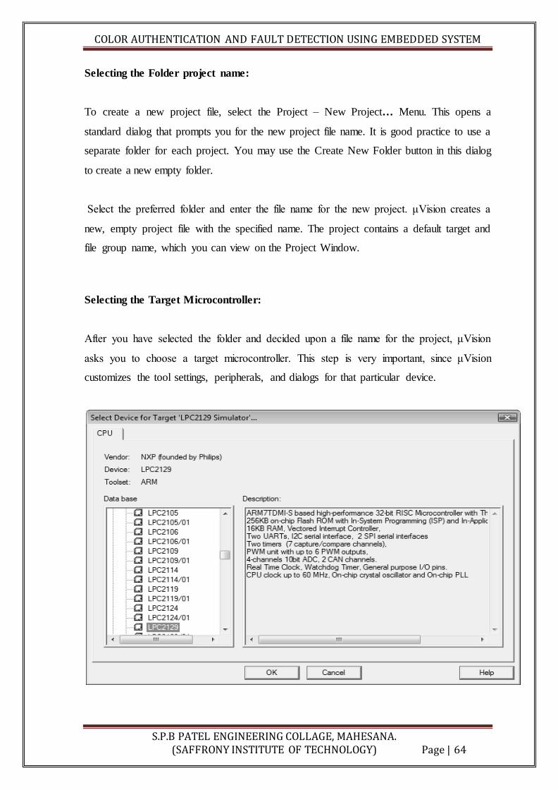
Selecting the Target Microcontroller:
After you have selected the folder and decided upon a file name for the project, μVision
asks you to choose a target microcontroller. This step is very important, since μVision
customizes the tool settings, peripherals, and dialogs for that particular device.

COLOR AUTHENTICATION AND FAULT DETECTION USING EMBEDDED SYSTEM
S.P.B PATEL ENGINEERING COLLAGE, MAHESANA. (SAFFRONY INSTITUTE OF TECHNOLOGY) Page | 65
Copying the startup code:
All embedded programs require some kind of microcontroller initialization or Startup
code1, 2 that is dependent of the tool chain and hardware you will use. It is required to
specify the starting configuration of your hardware.
All Keil tools include chip-specific startup code for most of the devices listed in the
Device Database. Copy the startup code to your project folder and modify it there only.
μVision automatically displays a dialog to copy the startup code into your project folder.
Answer this question with YES. μVision will copy the startup code to your project folder
and adds the startup file to the project.
The startup code files are delivered with embedded comments used by the Configuration
wizard to provide you with a GUI interface for startup Configuration.
Using the project window:
Once you have created a project file successfully, the Project Window shows the targets,
groups, and files of your project. By default, the target name is set to Target 1, while the
group’s name is Source Group 1.
The file containing the startup code is added to the source group. Any file, the startup file
included, may be moved to any other group you may define in future.

COLOR AUTHENTICATION AND FAULT DETECTION USING EMBEDDED SYSTEM
S.P.B PATEL ENGINEERING COLLAGE, MAHESANA. (SAFFRONY INSTITUTE OF TECHNOLOGY) Page | 66
Creating Source File:
Use the button on the File Toolbar or the select the File – New… Menu to create a
new source file
This action opens an empty Editor Window to enter your source code. μVision enables
color syntax highlighting based on the file extension (after you have saved the file). To
use this feature immediately, save the empty file with the desired extension prior to
starting coding.
Save the new source file using the button on the File Toolbar or use the File –
Save Menu
Adding source file to project:
After you have created and saved your source file, add it to the project Files existing in
the project folder, but not included in the current project structure, will not be compiled.
Right-click a file group in the Project Window and select Add Files to Group from the
Context Menu. Then, select the source file or source files to be added. A self-
explanatory window will guide you through the steps of adding a file
.

COLOR AUTHENTICATION AND FAULT DETECTION USING EMBEDDED SYSTEM
S.P.B PATEL ENGINEERING COLLAGE, MAHESANA. (SAFFRONY INSTITUTE OF TECHNOLOGY) Page | 67
Setting Target Option:
Open the Options for Target dialog from the Build Toolbar or from the Project Menu
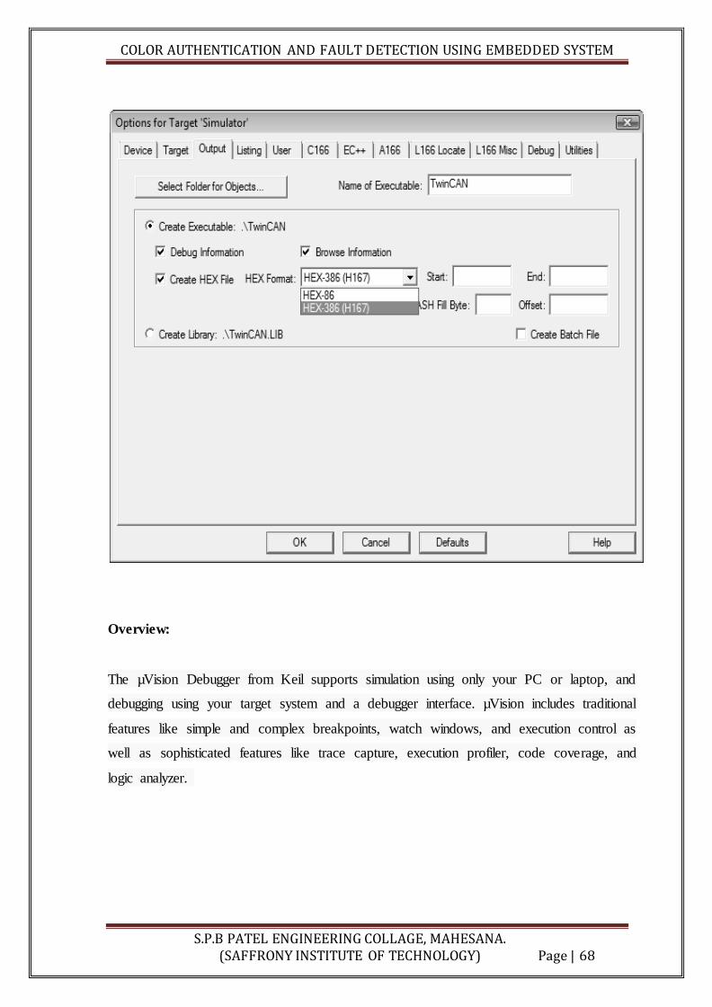
Creating Hex File:
Check the Create HEX File box under Options for Target — Output, and
μVision will automatically create a HEX file during the build process.
Select the desired HEX format through the drop-down control to generate formatted HEX
files, which are required on some Flash programming utilities.
COLOR AUTHENTICATION AND FAULT DETECTION USING EMBEDDED SYSTEM
S.P.B PATEL ENGINEERING COLLAGE, MAHESANA. (SAFFRONY INSTITUTE OF TECHNOLOGY) Page | 68
Overview:
The µVision Debugger from Keil supports simulation using only your PC or laptop, and
debugging using your target system and a debugger interface. µVision includes traditional
features like simple and complex breakpoints, watch windows, and execution control as
well as sophisticated features like trace capture, execution profiler, code coverage, and
logic analyzer.
COLOR AUTHENTICATION AND FAULT DETECTION USING EMBEDDED SYSTEM
S.P.B PATEL ENGINEERING COLLAGE, MAHESANA. (SAFFRONY INSTITUTE OF TECHNOLOGY) Page | 69
ANNEXURE D: PROJECT DOMAIN
Embedded:
This domain has so many ideas to perform infinite application and any type of task as
well as processors and controllers. Embedded domain has processors like ARM series
which is very popular and used to cover any type of specific application area.
Embedded System:
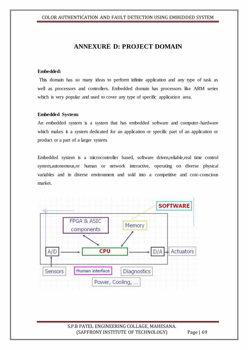
An embedded system is a system that has embedded software and computer-hardware
which makes it a system dedicated for an application or specific part of an application or
product or a part of a larger system.
Embedded system is a microcontroller based, software driven,reliable,real time control
system,autonomous,or human or network interactive, operating on diverse physical
variables and in diverse environment and sold into a competitive and cost-conscious
market.

COLOR AUTHENTICATION AND FAULT DETECTION USING EMBEDDED SYSTEM
S.P.B PATEL ENGINEERING COLLAGE, MAHESANA. (SAFFRONY INSTITUTE OF TECHNOLOGY) Page | 70
Embedded Components:
It embeds hardware similar to a computer. Figure 2.2 shows the units in
the hardware of an embedded system. As its software usually embeds in
the ROM or flash memory, it usually do not need a secondary hard disk
and CD memory as in a computer.
It embeds main application software. The application software may
concurrently perform a series of tasks or processes or threads.
It embeds a real time operating (RTOs) that supervises the application
running on hardware and organizes access to a resource according to the
priorities of tasks in the system.

COLOR AUTHENTICATION AND FAULT DETECTION USING EMBEDDED SYSTEM
S.P.B PATEL ENGINEERING COLLAGE, MAHESANA. (SAFFRONY INSTITUTE OF TECHNOLOGY) Page | 71
Embedded Structure:
Embedded Characteristic:
Embedded systems do specific task
Embedded systems have limited resources particularly memory (Do not have
CD/DVD ROM or huge data storage device)
Embedded systems have deadlines. Certain tasks have to be completed in time
otherwise damage such as loss of life may occur.
Power consumption must be low as most of embedded systems operated by
battery
Must be highly reliable (No CTRL+ALT+DEL!)
Should work in extreme environment conditions
It should be economical (low cost)

COLOR AUTHENTICATION AND FAULT DETECTION USING EMBEDDED SYSTEM
S.P.B PATEL ENGINEERING COLLAGE, MAHESANA. (SAFFRONY INSTITUTE OF TECHNOLOGY) Page | 72
Embedded Application:
Consumer appliances
Industrial Automation
Medical Electronics
Computer Networking
Telecommunications
Wireless technologies
Instrumentation
Embedded System Examples:
Point of sales terminals: automatic chocolate vending machine.
Stepper motor controllers for a robotics system.
Washing or cooking systems.
Multitasking toys.
Keyboard controller.
Electronic data acquisition and supervisory control system.
Spectrum analyzer.
Fax or photocopy or printer or scanner machine.
Motor control systems.
Mobile smart phones and computing systems.
Biomedical systems such as an ECG LCD display cum recorder, a blood-cell
recorder cum analyzer, and a patient monitor system.