collaborative manufacturing network for competitive advantage · project title collaborative...
TRANSCRIPT

284928
Collaborative Manufacturing Network
for Competitive Advantage
D8.4.1 – Mobile Maintenance
Adaption of Mobile Collaboration Concept
(public)

D8.4.1 – Adaption of Mobile Collaboration Concept
WP8 – Mobile Collaboration
© ComVantage Consortium – 2012 2
Grant Agreement No. 284928
Project acronym ComVantage
Project title Collaborative Manufacturing Network for Competitive Advantage
Deliverable number D8.4.1
Deliverable name Adaption of mobile collaboration concept
Version V 1.0
Work package WP 8 – Mobile Maintenance
Lead beneficiary TUD
Authors Johannes Pfeffer (TUD), Jens Ziegler (TUD), Steffen Buzin (SAP), Gali Naveh (BGU), Andreas Schmid (K&A), Werner Altman (K&A), Frank Haferkorn (RST)
Reviewers Conny Weber (ISN), Oscar Lazaro (Innovalia)
Nature R – Report
Dissemination level PU – Public
Delivery date 31/10/2012 (M14)

D8.4.1 – Adaption of Mobile Collaboration Concept
WP8 – Mobile Collaboration
© ComVantage Consortium – 2012 3
Executive Summary
Deliverable D8.4.1 describes the procedure and the results of the adaptation of the concepts of intuitive and trustful mobile interaction introduced in work package 5. Based on deliverable D8.1.1 the scenario Corrective Maintenance Customer Initiated was chosen as an exemplary scenario for a first adaptation of the generic UI models and workflows. Both the user interface concepts and the generic software architecture have been extended and modified according to a software requirements specification provided by the application partner. All modifications and extensions are closely aligned with the results of the deliverables D8.2.1 and D8.3.1. The Business Evaluation Framework introduced in work package 9 has been adapted to the given application area to allow a first evaluation. As a result of the adaptation process, the deliverable provides a set of recommendations for implementation of the first adapted mockup prototype in work package 11 and concept for the evaluation of the adapted prototype in work package 5.

D8.4.1 – Adaption of Mobile Collaboration Concept
WP8 – Mobile Collaboration
© ComVantage Consortium – 2012 4
Table of Contents
1 OVERVIEW ..................................................................................................................................... 7
1.1 INTRODUCTION .................................................................................................................................... 7
1.2 SCOPE OF THIS DOCUMENT .................................................................................................................... 7
1.3 RELATED DOCUMENTS ........................................................................................................................... 7
2 ADAPTATION OF THE GENERIC CONCEPTS OF MOBILE COLLABORATION ......................................... 8
2.1 SOFTWARE REQUIREMENTS SPECIFICATION ............................................................................................... 8
2.1.1 P1 Corrective MM – RS – START Repair Scenario .................................................................... 8
2.1.2 P1 Corrective MM – RS – DO Repair Scenario ....................................................................... 10
2.1.3 P1 Corrective MM – RS – Repair and Validation ................................................................... 11
2.1.4 P1 Corrective MM – RS – Find Defect ................................................................................... 14
2.1.5 P1 Corrective MM – RS – Validate Machine in NON Operating Mode ................................. 16
2.1.6 P1 Corrective MM – RS – Validate Machine in Operating Mode .......................................... 17
2.1.7 P1 Corrective MM – Finalise Service Report ......................................................................... 19
2.2 ADAPTATION OF THE CONCEPTUAL SOFTWARE DESIGN ............................................................................. 20
2.2.1 Compliance with the Concepts of Work Package 5 ............................................................... 20
2.2.2 Use Case Specific Adaptations of the User Interface ............................................................ 20
2.2.3 Candidates for Adapted Generic Apps .................................................................................. 31
2.2.4 Mockup Workflow: Analysing a Heat Sensor ........................................................................ 31
2.2.5 Use Case Specific Adaptations of the Software Architecture ............................................... 41
2.2.6 Use Case Specific Adaptations of the Business Evaluation Framework ................................ 42
2.3 VALIDATION OF THE ADAPTED SOFTWARE DESIGN ................................................................................... 44
2.4 EVALUATION CONCEPT FOR THE ADAPTED SOFTWARE DESIGN ................................................................... 44
2.4.1 Scope of the Planned Evaluations of the Adapted Software Design ..................................... 45
2.4.2 Setting.................................................................................................................................... 45
2.4.3 Experiment Design ................................................................................................................ 46
3 CONCLUSION AND OUTLOOK........................................................................................................ 46
4 GLOSSARY .................................................................................................................................... 47
5 REFERENCES ................................................................................................................................. 48

D8.4.1 – Adaption of Mobile Collaboration Concept
WP8 – Mobile Collaboration
© ComVantage Consortium – 2012 5
List of Figures
Figure 1: Workflow of “START Repair Scenario” ................................................................................................ 9 Figure 2: Workflow of DO Repair Scenario ....................................................................................................... 11 Figure 3: Workflow of Repair and Validation ................................................................................................... 13 Figure 4: Workflow of Find Defect .................................................................................................................... 15 Figure 5: Workflow of Validate Machine in NON Operating Mode.................................................................. 17 Figure 6: Workflow of Validate Machine in Operating Mode .......................................................................... 18 Figure 7: Workflow of Finalise Service Report .................................................................................................. 19 Figure 8: Adonis Workflow of START Repair Scenario ...................................................................................... 21 Figure 9: Adonis Workflow of Identify Machine ............................................................................................... 22 Figure 10: Adonis Workflow of DO Repair Scenario ......................................................................................... 23 Figure 11: Adonis Workflow of Repair and Validation ..................................................................................... 25 Figure 12: Workflow of Find Defect .................................................................................................................. 27 Figure 13: Workflow of Validate Machine in NON Operating Mode................................................................ 28 Figure 14: Workflow of Validate Machine in Operating Mode ........................................................................ 29 Figure 15: Workflow of Finalise Service Report ................................................................................................ 30 Figure 16: Setting Machine in NON-Operating State ....................................................................................... 32 Figure 17: Finding Machine Defect ................................................................................................................... 34 Figure 18: Reading Sensor 01 ........................................................................................................................... 35 Figure 19: Visualising Sensor Data .................................................................................................................... 36 Figure 20: Reading History Data ....................................................................................................................... 37 Figure 21: Visualising History Data ................................................................................................................... 38 Figure 22: Running Maintenance Test Cases .................................................................................................... 39 Figure 23: Visualising Test Results .................................................................................................................... 40 Figure 24: Expected Impact on Operational Effects ......................................................................................... 43 Figure 25: Expected Direct Impact on Supply Chain Processes ........................................................................ 43 Figure 26: Reflection Level of Metrics .............................................................................................................. 44 Figure 27: The ComVantage UCD Lifecycle (D5.1.1) ........................................................................................ 45

D8.4.1 – Adaption of Mobile Collaboration Concept
WP8 – Mobile Collaboration
© ComVantage Consortium – 2012 6
List of Tables
Table 1: Different types of evaluation with respect to the evaluation target (D5.1.1) .................................... 45

D8.4.1 – Adaption of Mobile Collaboration Concept
WP8 – Mobile Collaboration
© ComVantage Consortium – 2012 7
1 OVERVIEW
1.1 Introduction
As introduced in D5.3.1, orchestration of mobile apps has its starting point in the selection of suitable generic apps for all involved tasks of a mobile app-supported workflow. As a second step, those generic apps have to be adapted to the requirements of the particular context of use. This adaptation guarantees best-possible suitability for the task and may require more or less effort, depending on this context and the quality of the generic apps. Part of this effort is to be automated, while others will remain manual labor. The concept of app orchestration is going to be realised in the ComVantage Industrial App Framework. While App orchestration is a rather universal concept the implementation needs to be adapted to specific use case needs.
1.2 Scope of this Document
The purpose and scope of this document is the description of the procedure and the results of the adaptation of the concepts of intuitive and trustful mobile interaction introduced in work package 5 to the first exemplary scenario of work package 8 being the scenario Corrective Maintenance Customer initiated The content of this document shall serve as foundation for the implementation of the mockup prototype, its validation and usability evaluation. It shall further advance the development of the Business Evaluation Model.
1.3 Related Documents
The software requirements specification is based on the Initial set of requirements based on exemplary use cases introduced in D2.1.1: Functional and Technological Requirements and the first selected use cases elaborated in D8.1.1: Mobile Maintenance – Scenario specification and refinement.
The evaluation concept is based on the preliminary version of the usability & trust metrics toolkit introduced in D5.1.1: Metrics for Usability and Trust.
The use case specific adaptations of the User Interfaces mainly refer to the basic presentation and workflow models introduced in D5.2.1: UI Presentation and Workflow Models.
The use case specific adaptations of the software architecture mainly refer to the generic concepts and the runtime framework introduced in D5.3.1: UI Modelling and Generation Framework.
All modifications and extensions have been closely aligned with the results of the deliverables D8.2.1: Mobile Maintenance – Adaption of Secure Information Model Concept and D8.3.1: Mobile Maintenance Adaption of Linked Data Integration Concept, which were created in parallel. Further, care was taken to preserve the greatest possible consistency with the deliverables D6.4.1: Plant Engineering and Commissioning – Adaption of Mobile Collaboration Concept and D7.4.1: Customer-oriented Production – Adaption of Mobile Collaboration Concept.
The use case specific adaptations of the Business Evaluation Framework are based on the conceptual evaluation framework introduced in D9.1: Evaluation Framework and mainly refer to the set of relevant metrics and their definitions for this framework that have been introduced in D9.2.2: Multidimensional Metric Set.
This deliverable will serve as a foundation for the implementation of the mockup prototype in D11.3.1: Prototypical Implementation of Mobile Maintenance and for the usability evaluation of this prototype in

D8.4.1 – Adaption of Mobile Collaboration Concept
WP8 – Mobile Collaboration
© ComVantage Consortium – 2012 8
D5.1.2: Metrics for Usability and Trust. It will further have direct impact on the development of the simulation model for comparing alternative ComVantage processes in D9.3.1: Simulation Analysis Report.
2 ADAPTATION OF THE GENERIC CONCEPTS OF MOBILE COLLABORATION
2.1 Software Requirements Specification
With respect to the first prototype supporting the Mobile Maintenance application area we chose the following scenario from D8.1.1 and the corresponding requirements with respect to the intended user interfaces:
4.2.2 Scenario Corrective Maintenance Customer initiated (D8.1.1, page 29).
This scenario won’t be covered completely. Only the involvement of the Service Technician (SvTn) and the Machine Expert (ME) will be covered. Hence, all interaction with a CRM-system will be excluded. The SvTn and the ME will be summarised by the term Repair Scenario Operator (RSOp) who will stand for the SvTn as far as the SvTn can solve the maintenance problem on his/her own or for the ME, otherwise. This way the design of an Adapted App that serves both the purposes of the SvTn and the ME can be eased as both are to use a common app. The SvTn’s and the ME’s involvement will be reflected by the following sub scenarios which in turn involve the Adapted App.
The requirements we draw from the scenario have references to the respective requirement in the ComVantage FusionForge requirements entry (e.g. Requirement_###).
Sub scenarios of 4.2.2 from D8.1.1 involving the Adapted App:
1. P1 Corrective MM – RS – START Repair Scenario
2. P1 Corrective MM – RS – DO Repair Scenario
3. P1 Corrective MM – RS – Repair and Validation
4. P1 Corrective MM – RS – Find Defect
5. P1 Corrective MM – RS – Validate Machine in NON Operating Mode
6. P1 Corrective MM – RS – Validate Machine in Operating Mode
7. P1 Corrective MM – Finalise Service Report
Requirements:
Those covering the above sub scenarios given high Priority, those covered by 4.2.2 Scenario Corrective Maintenance Customer initiated but not by the above sub scenarios were given low priority and those not even covered by 4.2.2 Scenario Corrective Maintenance Customer initiated were completely omitted.
Related notes:
P1: Machine is set in NON operating mode to enable the run of maintenance tests and to access to actuators.
P2: Running maintenance tests and access to actuators is possible during machine’s operation.
2.1.1 P1 Corrective MM – RS – START Repair Scenario
Precondition:
Machine and test semantics have been published on start-up and are therefore available for use.

D8.4.1 – Adaption of Mobile Collaboration Concept
WP8 – Mobile Collaboration
© ComVantage Consortium – 2012 9
Summary:
The RSOp identifies the defective machine via an Adapted App: Display of Machine ID/entry point of LD. (please see Requirement_325)
The RSOp enters a short description of defect (please see Requirement_336)
The RSOp initiates a Service Report containing:
a. date/time (begin)
b. the name of RSOp
c. the machine’s location (please see Requirement_330)
d. the machine’s ID
The RSOp repairs the machine.
The RSOp finalises the service report:
a. Error description
b. Repair solution
c. List of changed spare parts
d. List of work efforts
e. date/time (end)
See Figure 1: Workflow of “START Repair Scenario”.
Figure 1: Workflow of “START Repair Scenario”

D8.4.1 – Adaption of Mobile Collaboration Concept
WP8 – Mobile Collaboration
© ComVantage Consortium – 2012 10
Requirements
Priority: High
ID: 306: The Service Technician has to have the permission to access to the Machine
ID: 316: The Service Technician has to have access to all relevant Machine data
ID: 317: The SvTn has to be granted security clearance to visit the Customer’s site.
ID: 319: The SvTn has to have Internet and Intranet access
ID: 325: The support app has to be able to identify a machine using machine-readable markers.
ID: 330: The support app has to make use of a positioning system
ID: 336: The support app has to be able to take pictures of the Machine’s defects
Priority: Low
ID: 322: The support app can initiate a repair request on demand of a MMCo
ID: 326, 327, 329, 332, 333, 335: Clearly excluded because MMCo is involved
ID: 342: The support app has to be able to give deeper insight in problems (Insight based on info not provided by either SvTn or ME, this goes beyond the repair scenario)
ID: 368: The Service Technician has to be able to receive a repair request (triggered by CUSTOMER or MMCo and therefore beyond the repair scenario)
ID: 547: The SvTn has to be able to send a repair request (As receiving a repair request is excluded the same must be true for sending one)
ID: 548: The Customer has to be able to send a repair request (triggered by CUSTOMER and therefore beyond repair scenario)
2.1.2 P1 Corrective MM – RS – DO Repair Scenario
Precondition:
All steps preceding the DO Repair Scenario (see Figure 1: Workflow of “START Repair Scenario”) are done.
Summary:
The RSOp gets machine’s semantic, visualisation semantic and test semantic via LD entry point for the defective machine. The RSOp sets the machine to NON operating mode or to maintenance state. He or she starts the repair and validation process.
See Figure 2: Workflow of DO Repair Scenario

D8.4.1 – Adaption of Mobile Collaboration Concept
WP8 – Mobile Collaboration
© ComVantage Consortium – 2012 11
Figure 2: Workflow of DO Repair Scenario
Requirements
The essential part of DO Repair Scenario is repair and validation. The sequence preceding Repair and Validation in DO Repair Scenario merely prepares things for repair and validation. Hence, DO Repair Scenario is covered by the same requirements as repair and validation (see P1 Corrective MM – RS – Repair and Validation).
2.1.3 P1 Corrective MM – RS – Repair and Validation
Precondition:
Machine is in NON operating mode.
Summary:
The RSOp decides on a method to find the machine’s defect (please see Requirement_321).
His/her choices are:
a. read current sensor data
b. read history data (sensor/actuators)

D8.4.1 – Adaption of Mobile Collaboration Concept
WP8 – Mobile Collaboration
© ComVantage Consortium – 2012 12
c. read/write actuators
d. read history test results
e. run maintenance test case
The RSOp starts a request (using the chosen method to find the defect) via the Adapted App to get an adequate response.
The RSOp continues with these requests until he has identified the machine’s defect.
The RSOp repairs the machine after having identified the machine’s defect.
The RSOp validates the machine in NON operating mode and subsequently in operating mode.
The RSOp repeats the above steps until the tests are OK in both modes.
See Figure 3: Workflow of Repair and Validation

D8.4.1 – Adaption of Mobile Collaboration Concept
WP8 – Mobile Collaboration
© ComVantage Consortium – 2012 13
Figure 3: Workflow of Repair and Validation
Requirements
Priority: High
ID: 321: The SvTn has to be able to detect defect parts

D8.4.1 – Adaption of Mobile Collaboration Concept
WP8 – Mobile Collaboration
© ComVantage Consortium – 2012 14
2.1.4 P1 Corrective MM – RS – Find Defect
Precondition:
Defect is not yet found.
Introduction:
The following components were introduced in deliverable D2.2.1. They will be used in Figure 4: Workflow of Find Defect with the abbreviations as shown below.
WP2: Query Interface (Web Layer) former Request-Handler (part of DHM Web Server) – abbr.: Q/I
WP2: Access Control Interface (Web Layer) former Access-Control (part of DHM Web Server) – abbr.: A/C
WP2: DHM Adapter (Domain Source Layer) contains Job-Controller – abbr.: J/C
WP2: Middleware Controller (Domain Source Layer) former Data Harmonisation Middleware – abbr.: M/C
WP2: SPARQL Endpoint & Adapter (Domain Source Layer) container of History Data
Summary:
Common part:
The Query Interface analyses the request, checks the access rights of the request using Access Control and passes the request on to the Job-Controller if the access rights are sufficient.
Method specific part:
In case the methods Read Current Sensor Data/Actuators or Write Actuators were chosen:
After job dispatching the defective machine’s data is accessed via Life Data and the Middleware Controller according to Exclusive Write, Read many per machine.
Sensors/actuators are read or actuators are set. Having received info on current data or written actuators the Query Interface creates an adequate
response with the read sensors/actuators or set actuators and sends the response back to the RSOp via the Adapted App.
In case the methods Read History Data or Read History Test Results were chosen:
After job dispatching History Data is accessed. Having received info on history data the Query Interface creates the adequate response containing
the requested history data and sends it back to the RSOp via the Adapted App.
In case the method Run Maintenance Test Cases was chosen:
After job dispatching tests are scheduled for execution by the Test Execution Environment (subcomponent of the DHM Adapter) which in turn runs the maintenance Test using the Middleware Controller. On test completion the Test Execution Environment stores the test results in History Data.
Having received a test finished notification the Query Interface creates the adequate response and sends it back to the RSOp via the Adapted App.

D8.4.1 – Adaption of Mobile Collaboration Concept
WP8 – Mobile Collaboration
© ComVantage Consortium – 2012 15
Figure 4: Workflow of Find Defect
Requirements
Method to requirement mapping:
a. read current sensor data (please see Requirement_334+338)
b. read history data (sensor/actuators) (please see Requirement_339+355)
c. read/write actuators (please see Requirement_334+337+338)
d. read history test results (please see Requirement_339+355)
e. run maintenance test case (please see Requirement_320)
Priority: High
ID: 320: The Service Technician has to be able to test the machine
ID: 334: Machine’s Process Variables have to be readable.
ID: 337: Machine’s Process Variables have to be writable.
ID: 338: SvTn has to be able to visualise machine’s sensor and process data
ID: 339: The support app has to be able to browse data
ID: 355: There has to be a visualisation of the history of the machines’ operational states

D8.4.1 – Adaption of Mobile Collaboration Concept
WP8 – Mobile Collaboration
© ComVantage Consortium – 2012 16
Priority: Low
ID: 340: ME has access to enhanced tools for visualisation of machine’s sensor and process data (Reason: Goes beyond usage of Adapted Apps!)
We assume that machine experts (ME) will have more diagnosis tools and features than those which will be available through Adapted Apps!
2.1.5 P1 Corrective MM – RS – Validate Machine in NON Operating Mode
Precondition:
Machine is repaired and is still in NON Operating Mode.
Introduction:
The following components were introduced in deliverable D2.2.1. They will be used in Figure 5: Workflow of Validate Machine in NON Operating Mode with the abbreviations as shown below.
WP2: Query Interface (Web Layer) former Request-Handler (part of DHM Web Server) – abbr.: Q/I
WP2: Access Control Interface (Web Layer) former Access-Control (part of DHM Web Server) – abbr.: A/C
WP2: DHM Adapter (Domain Source Layer) contains Job-Controller – abbr.: J/C
WP2: Middleware Controller (Domain Source Layer) former Data Harmonisation Middleware – abbr.: M/C
WP2: SPARQL Endpoint & Adapter (Domain Source Layer) container of History Data
Summary:
The Query Interface analyses the request, delegates checking the access rights of the request to Access Control and passes the request on to the Job-Controller if the access rights are sufficient.
After job dispatching tests are scheduled for execution by the Test Execution Environment (subcomponent of the DHM Adapter) which in turn runs the maintenance Test using the Middleware Controller. On test completion the Test Execution Environment stores the test results in History Data.
Having received a test finished notification the Query Interface gets the last results from History Data analyses them and creates an adequate response denoting if the machine is OK or not.
The Query Interface then sends it back to the RSOp via the Adapted App.

D8.4.1 – Adaption of Mobile Collaboration Concept
WP8 – Mobile Collaboration
© ComVantage Consortium – 2012 17
Figure 5: Workflow of Validate Machine in NON Operating Mode
Requirements
Priority: High
ID: 320: The Service Technician has to be able to test the machine
ID: 334: Machine’s Process Variables have to be readable.
ID: 337: Machine’s Process Variables have to be writable.
ID: 339: The support App has to be able to browse data
2.1.6 P1 Corrective MM – RS – Validate Machine in Operating Mode
Precondition:
Machine is repaired and is in Operating Mode.
Introduction:
The following components were introduced in deliverable D2.2.1. They will be used in Figure 6: Workflow of Validate Machine in Operating Mode with the abbreviations as shown below.
WP2: Query Interface (Web Layer) former Request-Handler (part of DHM Web Server) – abbr.: Q/I
WP2: Access Control Interface (Web Layer) former Access-Control (part of DHM Web Server) – abbr.: A/C
WP2: DHM Adapter (Domain Source Layer) contains Job-Controller – abbr.: J/C
WP2: Middleware Controller (Domain Source Layer) former Data Harmonisation Middleware – abbr.: M/C
WP2: SPARQL Endpoint & Adapter (Domain Source Layer) container of History Data

D8.4.1 – Adaption of Mobile Collaboration Concept
WP8 – Mobile Collaboration
© ComVantage Consortium – 2012 18
Summary:
The Query Interface analyses the request, delegates checking the access rights of the request to Access Control and passes the request on to the Job-Controller if the access rights are sufficient.
After job dispatching tests are scheduled for execution by the Test Execution Environment (subcomponent of the DHM Adapter) which in turn runs the maintenance Test using the Middleware Controller. On test completion the Test Execution Environment stores the test results in History Data.
Having received a test finished notification the Query Interface gets the last results from History Data analyses them and creates an adequate response denoting if the machine is OK or not.
The Query Interface then sends it back to the RSOp via the Adapted App.
See Figure 6: Workflow of Validate Machine in Operating Mode
Figure 6: Workflow of Validate Machine in Operating Mode
Requirements
Priority: High
ID: 320: The Service Technician has to be able to test the machine
ID: 334: Machine’s Process Variables have to be readable.
ID: 337: Machine’s Process Variables have to be writable.
ID: 339: The support App has to be able to browse data

D8.4.1 – Adaption of Mobile Collaboration Concept
WP8 – Mobile Collaboration
© ComVantage Consortium – 2012 19
2.1.7 P1 Corrective MM – Finalise Service Report
Summary:
An Adapted App provides the user with the ability to:
1. enter an error and a solution description
2. list changed spare parts and the work efforts
3. finalise the report
An Adapted App adds the date/time of the end of the repair actions.
An Adapted App notifies that all actions related to the repair scenario have finished to the user.
See Figure 7: Workflow of Finalise Service Report
Figure 7: Workflow of Finalise Service Report

D8.4.1 – Adaption of Mobile Collaboration Concept
WP8 – Mobile Collaboration
© ComVantage Consortium – 2012 20
Requirements
ID: 324: The Service Technician has to finalise the service report
2.2 Adaptation of the Conceptual Software Design
2.2.1 Compliance with the Concepts of Work Package 5
Work package 5 will support the navigation design by an App Linker component and a Navigation Design Creator component that creates the navigation design (for details refer to D5.3.1). The latter derives a navigation design from a given business process or workflow model provided by the ComVantage meta-modelling platform (D3.1.1) which is based on the Adonis modelling tool1.
The App Linker places in-app links and populates context menus. All information the linker needs for these purposes may be provided by Adonis.
If the navigation design will be supported by the App Linker and the Navigation Design Creator to the greatest possible extent it will be fully automated.
Manually replacing the roles of the App Linker and the Navigation Design Creator we will derive a navigation design from the underlying business process or workflow models (Fischer, 2011) in which the above apps will be integrated.
2.2.2 Use Case Specific Adaptations of the User Interface
We now change our focus away from the requirements towards the design of visual mockups on the basis of the requirements identified in the previous section. Of course, we will use the scenarios known from the previous section:
1. P1 Corrective MM – RS – START Repair Scenario
2. P1 Corrective MM – RS – DO Repair Scenario
3. P1 Corrective MM – RS – Repair and Validation
4. P1 Corrective MM – RS – Find Defect
5. P1 Corrective MM – RS – Validate Machine in NON Operating Mode
6. P1 Corrective MM – RS – Validate Machine in Operating Mode
7. P1 Corrective MM – Finalise Service Report
All above scenarios have been described by UML SDs (for the UML specification, please see OMG, 2011) as such diagrams serve us well dealing with requirements. Yet, in compliance with 4.3.6 The Process Model Type (see D3.1.1) Adonis models are to serve as the starting point for the design of what work package 5 describes as Orchestrated Apps using Generic Apps selected from a pool of such apps. While D3.1.1 suggests the explicit assignment of generic apps to an Adonis activity or aggregation of activities, work package 5 follows the approach of using a Model-App-Comparator to reconcile the task model with the available app description to support the selection of the most appropriate generic app. This requires the enrichment of Adonis with information this comparison can be based upon.
For the purposes of this document we will explicitly assign self-contained apps with a clearly defined purpose to the respective Adonis tasks as neither work package 5’s Model-App-Comparator nor the above mentioned necessary information in Adonis are available as prototypes, yet.
1 http://www.adonis-community.com/

D8.4.1 – Adaption of Mobile Collaboration Concept
WP8 – Mobile Collaboration
© ComVantage Consortium – 2012 21
P1 Corrective MM – RS – START Repair Scenario
Summary:
The RSOp identifies the defective machine using the Adapted App. He or she enters a short description of the defect. The RSOp then initiates a Service Report, continues with the repair scenario and concludes by finalising the service report. For reasons of clarity we will cover RS Identify Machine by a separate diagram.
See Figure 8: Adonis Workflow of START Repair Scenario
Figure 8: Adonis Workflow of START Repair Scenario

D8.4.1 – Adaption of Mobile Collaboration Concept
WP8 – Mobile Collaboration
© ComVantage Consortium – 2012 22
Summary of RS Identify Machine
The RSOp identifies the defective machine using the Adapted App. In case a QR-Code should not be available he or she will enter the Machine’s ID manually. This is what we will focus on here.
See Figure 9: Adonis Workflow of Identify Machine
Figure 9: Adonis Workflow of Identify Machine
Adapted Apps
Enter Machine Identity manually (only NO QR-Code available-branch to be covered for the time being)
Enter Short Defect Description

D8.4.1 – Adaption of Mobile Collaboration Concept
WP8 – Mobile Collaboration
© ComVantage Consortium – 2012 23
Initiate Service Report Comment: In this example we do not cover the complete scenario. Scanning the QR-Code is omitted.
(Apps for DO Repair Scenario and RS Finalise Service Report will be covered by the following section.)
P1 Corrective MM – RS – DO Repair Scenario
Summary:
The RSOp fetches the machine’s semantic. He or she sets the machine to NON operating state and starts the repair and validation process.
See Figure 10: Adonis Workflow of DO Repair Scenario
Figure 10: Adonis Workflow of DO Repair Scenario
Adapted Apps
DHM FETCH Machine Semantic could be done implicitly on entry of the scenario. In this case no app would have to cover this task. Yet, we could also fetch this information on explicit request by the RSOp in which case we would need an app.
D8.4.1 – Adaption of Mobile Collaboration Concept
WP8 – Mobile Collaboration
© ComVantage Consortium – 2012 24
Set Machine in NON-Operating State
(Apps for RS Repair and Validate will be covered by the following section.)
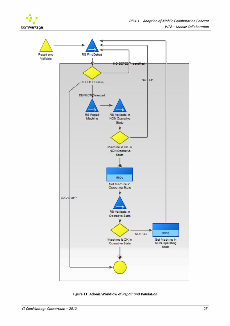
P1 Corrective MM – RS – Repair and Validation
Summary:
The RSOp tries to find the defect.
The RSOp then tries to repair the machine. He or she validates the machine in NON operating mode and subsequently in operating mode. The RSOp repeats the above steps until the tests are finally OK in both modes or until he finally gives up.
See Figure 11: Adonis Workflow of Repair and Validation.
D8.4.1 – Adaption of Mobile Collaboration Concept
WP8 – Mobile Collaboration
© ComVantage Consortium – 2012 25
Figure 11: Adonis Workflow of Repair and Validation
D8.4.1 – Adaption of Mobile Collaboration Concept
WP8 – Mobile Collaboration
© ComVantage Consortium – 2012 26
Adapted Apps
(Apps for RS Find Defect will be covered by the following section.)
(Apps for RS Validate in NON Operative State will be covered by one of the following sections.)
Set Machine in Operating State
(Apps for RS Validate in Operative State will be covered by one of the following sections.)
Set Machine in NON Operating State
P1 Corrective MM – RS Find Defect
The RSOp tries to find the defect using one of the methods below
a. read current sensor data
b. read history data (sensor/actuators)
c. read/write actuators
d. read history test results
e. run maintenance test case
He or she continues possibly sequentially trying several different methods until the machine’s defect is identified.
See Figure 12: Workflow of Find Defect

D8.4.1 – Adaption of Mobile Collaboration Concept
WP8 – Mobile Collaboration
© ComVantage Consortium – 2012 27
Figure 12: Workflow of Find Defect

D8.4.1 – Adaption of Mobile Collaboration Concept
WP8 – Mobile Collaboration
© ComVantage Consortium – 2012 28
Adapted Apps
Read Sensor Read/Write Actuator Read History Data (sensor, actuators, test results ) Run Maintenance Test Cases Visualise Data Try to identify Defect
P1 Corrective MM – RS – Validate Machine in NON Operating Mode
Summary:
Run a test suite that is dedicated to validations in NON operative mode.
See Figure 13: Workflow of Validate Machine in NON Operating Mode
Figure 13: Workflow of Validate Machine in NON Operating Mode

D8.4.1 – Adaption of Mobile Collaboration Concept
WP8 – Mobile Collaboration
© ComVantage Consortium – 2012 29
Adapted Apps
Run Validation of NON Operative Test Suites
P1 Corrective MM – RS Validate Machine in Operating Mode
Summary:
Run a test suite that is dedicated to validations in operative mode.
See Figure 14: Workflow of Validate Machine in Operating Mode .
Figure 14: Workflow of Validate Machine in Operating Mode
Adapted Apps
Run Validation of Operative Test Suites
P1 Corrective MM – Finalise Service Report
Summary:
The RSOp provides an error and a solution description. He or she lists changed spare parts and the work efforts and finally transmits the report
See Figure 15: Workflow of Finalise Service Report.

D8.4.1 – Adaption of Mobile Collaboration Concept
WP8 – Mobile Collaboration
© ComVantage Consortium – 2012 30
Figure 15: Workflow of Finalise Service Report
Adapted Apps
Report Error Description
Report Solution Description
List used spare Parts
List Work Effort
Transmit Service Report (may provide a summary and a button to trigger the transmission when pressed)

D8.4.1 – Adaption of Mobile Collaboration Concept
WP8 – Mobile Collaboration
© ComVantage Consortium – 2012 31
2.2.3 Candidates for Adapted Generic Apps
From the above workflows we derived the following possible Generic Apps:
Enter Machine Identity manually Enter Short Defect Description Initiate Service Report DHM FETCH Machine Semantic Set Machine in NON-Operating State Set Machine in Operating State Set Machine in NON Operating State Read Sensor Read/Write Actuator Read History Data Run Maintenance Test Cases Visualise Data Try to identify Defect Run Validation of NON Operative Test Suites Run Validation of Operative Test Suites Report Error Description Report Solution Description List used spare Parts List Work Effort Transmit Service Report
2.2.4 Mockup Workflow: Analysing a Heat Sensor
For the implementation of the prototype in Deliverable D11.3.1 (Prototypical implementation of Mobile Maintenance) we have chosen a justinmind PROTOTYPER tool2. With this tool the mockup could be designed easily and quickly.
To prove the software design construction we use functional calls on the level of browser-initiation to make use case functions runnable without having a connection to the really final user interface components designed in D5.3.1.
We chose a workflow that focuses on our special needs concerning the presentation of complex information depicted in e.g. diagrams. It is helpful and time saving to get a quick overview of the complete information at a single glance. Hence, we selected the Adonis workflow Find Defect. To ease things we named each of the following graphical mockups by the name of its Adonis task in Find Defect. Each mockup contains its name as a title.
In the examples we start immediately before the entry of Find Defect in Repair and Validation with the Adonis task named Set Machine in NON-Operating State.
Maintenance Test Cases have been fetched and the machine is in operating mode. This is denoted by an icon in the upper left corner on the tablet’s display. See Figure 16: Setting Machine in NON-Operating State.
2 http://www.justinmind.com/

D8.4.1 – Adaption of Mobile Collaboration Concept
WP8 – Mobile Collaboration
© ComVantage Consortium – 2012 32
Figure 16: Setting Machine in NON-Operating State
Control elements:
Operating State:
Denoting that the machine is currently in operating state. It reflects real time information that cannot be covered by Linked Data.
NON-Operating state:
Reflects the fact that the machine is currently in NON-operating state. We assume that the user needs to be kept informed about the current state of the machine he or she is dealing with in real-time. This symbol is used to mark the button that needs to be touched to switch from operating to NON-operating state in

D8.4.1 – Adaption of Mobile Collaboration Concept
WP8 – Mobile Collaboration
© ComVantage Consortium – 2012 33
the above mockup. We should use the same symbols/icons we used for marking buttons that we use for denoting e.g. the machine’s current state.
Previous step:
It might be useful to go back to the previous step. The user can do this by touching the button marked by the above symbol. The workflow should not be exited completely. Instead the preceding step in the active workflow has to be revisited.
Drop current:
Having re-visited the previous step in the workflow we might find it suitable to try different setting to be used by the current step. Drop current should drop ALL current settings to make sure we do not unintentionally keep parts of the old settings.
Description of Figure 16: Setting Machine in NON-Operating State:
In We need to continue in NON-operating State. We therefore touch the crossed out operating icon in the display center. Now we continue by trying to find the defect. We have four options and choose the first one.

D8.4.1 – Adaption of Mobile Collaboration Concept
WP8 – Mobile Collaboration
© ComVantage Consortium – 2012 34
Figure 17: Finding Machine Defect
Control elements:
The above buttons named Read Sensor, …, Run Maintenance Test Cases have the purpose of enabling the user to choose the most suitable method on the basis of his/her own assessment in the current situation.
Description of Figure 17: Finding Machine Defect:
As we see, the fact that the machine is in NON-operating state is denoted by a corresponding icon in the upper left corner of the display. This will be the case as long as the machine is in NON-operating state. Touching Read Sensor takes us to the Read Sensor dialog.

D8.4.1 – Adaption of Mobile Collaboration Concept
WP8 – Mobile Collaboration
© ComVantage Consortium – 2012 35
Figure 18: Reading Sensor 01
Control elements:
The Tree View:
In the above example only the sensor group of interest should be visible. They therefore do not become visible before their node in the tree view is expanded. Once the node is expanded we select the tree view node named by the sensor we are interested in.
Description of Figure 18: Reading Sensor 01:
Here we select the sensor to be analysed. Let this be Heat Sensor 01 for the purpose of the example. Clicking Heat Sensor 01 takes us to the visualisation of the current sensor data.

D8.4.1 – Adaption of Mobile Collaboration Concept
WP8 – Mobile Collaboration
© ComVantage Consortium – 2012 36
Figure 19: Visualising Sensor Data
Control elements:
Green thumb up:
We tell the device that we found the defect by touching this button.
Red thumb down:
We tell the device that we still have no clue on what is wrong and therefore return to the choice of methods to do further analysis by touching this button.
Description of Figure 19: Visualising Sensor Data:
If this information is sufficient for finding the defect we continue be touching the green thumb high button. Let’s assume we still have no clue. We therefore touch the red thumb low button. This takes us back to Finding the Machine Defect where we choose to have a look at the history.

D8.4.1 – Adaption of Mobile Collaboration Concept
WP8 – Mobile Collaboration
© ComVantage Consortium – 2012 37
Figure 20: Reading History Data
Description of Figure 20: Reading History Data:
We now have a look at the history of Heat Sensor 01 by touching the corresponding entry in the tree view.

D8.4.1 – Adaption of Mobile Collaboration Concept
WP8 – Mobile Collaboration
© ComVantage Consortium – 2012 38
Figure 21: Visualising History Data
Description of Figure 21: Visualising History Data:
Now, we have the chance to compare the last 3 (or more) different behaviors of the sensor. Let’s assume we still have no clue what the defect might be. So, we touch thumb low. Choose Run Maintenance Test Cases and fetch up at Running Maintenance Test Cases.

D8.4.1 – Adaption of Mobile Collaboration Concept
WP8 – Mobile Collaboration
© ComVantage Consortium – 2012 39
Figure 22: Running Maintenance Test Cases
Description of Figure 22: Running Maintenance Test Cases:
Again we touch Heat Sensor 01 to run its maintenance tests. This takes us to Visualising Test Results.

D8.4.1 – Adaption of Mobile Collaboration Concept
WP8 – Mobile Collaboration
© ComVantage Consortium – 2012 40
Figure 23: Visualising Test Results
Description of Figure 23: Visualising Test Results:
We finally know what is wrong and touch the green thumb up button which takes us out of this example.

D8.4.1 – Adaption of Mobile Collaboration Concept
WP8 – Mobile Collaboration
© ComVantage Consortium – 2012 41
2.2.5 Use Case Specific Adaptations of the Software Architecture
From the Software Requirements Specification (section 2.1), the use case specific adaptations of the user interface (section 2.2.1), the candidates for Adapted Generic Apps (section 2.2.3) and the mockup workflow (section 2.2.4) we have identified necessary adaptations of the Industrial App Framework (IAF) software architecture.
For the purpose of this deliverable the adaptation recommendations refer to the architecture implementation on the Android platform. In most cases, the same recommendations are applicable to the iOS platform which will be implemented in a later phase of the project.
Identified adaptations:
A The software architecture should be adapted to support status icons or a status bar (see Figure 16, e.g. “NON Operating State” / “Operating State”). In Android this can be realised as Status Notifications3 that are displayed in the system’s status bar (a ticker message notification is optional) or a custom status display within the app. Such a custom display may be better visible to the user but uses a lot of screen space. While the custom status display lies within the responsibility of each Generic/Adapted App, the Status Notification can be supported by the IAF.
B It should be possible to include real time information (e.g. “NON Operating State” / “Operating State”) in the status icons or the status bar (see Figure 16). Real time information can be included at any time by providing a mechanism to access and display such information in each Generic App individually. Whether the IAF can support this by offering interfaces to different real time data sources needs to be discussed during further development of the prototypes.
C At certain points in the workflow, there should be features for the user to choose between alternative routes through the workflow (see Figure 17). It is important to consider this adaptation when developing the Navigation Design Creator of the IAF design time framework and the Navigation Design component of the IAF runtime framework (see D5.3.1).
D There should be support for navigation between apps in both directions. This is not planned to be a core feature of the IAF prototype. However, a dedicated history app could provide access to the navigation path a user has taken.
E There should be support for a tree view or a similar presentation pattern that allows choosing from machine and device hierarchies (see Figure 18). Classical tree views are not very well suited for mobile devices with small screens. Android, for example, does not provide a dedicated tree view. Usually, navigation in hierarchical tree structures is accomplished through hierarchical lists. However, there are third party components available, that allow classical tree views to be used in Android apps. There is no need for the IAF to explicitly support tree views. Generic Apps that specialise on choosing from machine and device hierarchies are free to implement their own way of navigation through tree structures.
3 For Status Notifications in Android, please see
http://developer.android.com/guide/topics/ui/notifiers/notifications.html.

D8.4.1 – Adaption of Mobile Collaboration Concept
WP8 – Mobile Collaboration
© ComVantage Consortium – 2012 42
F Support for a function that clears all current values is needed (see Figure 17). The main functionality for this again lies in the responsibility of the Generic/Adapted App. In the case that communication with the IAF Message Board needs to be cleared, the IAF must be adapted to support this.
G Requirement 340 implies that it should be possible to interrupt the workflow, use an external tool that is not part of the IAF, and then resume the workflow where it was left off, optionally entering results from the external tool. The IAF components responsible for the navigation design need to be adapted to support this. Possible solutions may involve a “Pause App” in form of a Generic App that allows picking up a workflow back up after completing an external task.
2.2.6 Use Case Specific Adaptations of the Business Evaluation Framework
In order to assess the business value of ComVantage, an evaluation framework has been proposed in deliverable D9.2.1. The framework is focused on the links between IT assets, collaborative capabilities and organisational performance.
The organisational performance construct serves as a basis for defining a multi-dimensional metric set. It is composed of two orthogonal dimensions: the operational effects dimension which includes six performance aspects (cost, efficiency, quality, flexibility, innovation and sustainability) and the business process dimension which describes the focus of impact in terms of generic supply chain processes (supplier, inbound logistics, operation, outbound logistics, marketing and sales). This process-oriented perspective facilitates insights regarding value creation.
A multi-dimensional generic metric set was composed based on an extensive literature review. The metrics were categorised according to both operational effects and business processes dimensions. This generic list was adapted to the related business processes of the Mobile Maintenance application area, based on a high level analysis of its scenarios (detailed in D8.1.1). The main business processes in the Mobile Maintenance application area include corrective maintenance, preventive maintenance and predictive maintenance.
The adapted metric set was validated using questionnaires and interviews of key stakeholders in the Mobile Maintenance application partner, K&A and RST. In the questionnaire they were asked to assess, on a seven-point Likert scale, the extent to which each metric would reflect the expected change in business performance as a result of implementing ComVantage. In the interview, the interviewees were asked several general questions and their responses in the questionnaire were discussed. They were also asked to suggest further metrics, specific to the industry and the organisation in focus (for details see D9.2.2). The interviews revealed that the ComVantage platform is expected by the stakeholders to improve accessibility of the data from machines to experts “anytime and anyplace”, via mobile devices. This availability of data is expected to contribute to reduction of cost as well as to increase efficiency. The new capabilities are also expected to support innovative processes that should naturally evolve as a result of the new significantly improved internal processes. Consequently, the most relevant operational effects indicated as reflective of the change introduced by the new platform are cost, quality, efficiency and innovation (Figure 24).

D8.4.1 – Adaption of Mobile Collaboration Concept
WP8 – Mobile Collaboration
© ComVantage Consortium – 2012 43
Figure 24: Expected Impact on Operational Effects
The interviewees indicated that the supply chain stage expected to be mostly effected by the changes introduced, will be the internal and downstream (customers related) processes of the supply chain (Figure 25).
Figure 25: Expected Direct Impact on Supply Chain Processes
Figure 26 summarises the adaptation process and presents the expected reflection level of the adapted metric set in the Mobile Maintenance application area. Darker cells denote the existence of highly reflective metrics in the category, while lighter cells denote lower reflective metrics. White cells indicate no relevant metrics were found. The results suggest that all operational effects include metrics with high or medium degree of reflection, which is consistent with the major value adding areas of ComVantage in this application area. With respect to the business processes dimension, the highly reflective metrics refer mainly to the operation and marketing and sales processes, which belong to the internal and downstream parts of the supply chain.
Examples of highly reflective metrics in the efficiency-operation category suggested by the interviewees are Maintenance Response Time (MRT) and Mean Time to Repair (MTTR). MRT refers to the time elapsed between a service request and its corresponding response, while MTTR refers to the average time to repair a failed component or device. The complete list of the adapted metric set can be found in D9.2.2, section 5.3.

D8.4.1 – Adaption of Mobile Collaboration Concept
WP8 – Mobile Collaboration
© ComVantage Consortium – 2012 44
Dimension Supplier Inbound Operation Outbound Marketing and Sales
Cost 0 0 3 0 0
Efficiency 0 0 3 0 3
Quality 0 0 3 0 3
Flexibility 0 0 3 2 0
Innovation 0 0 3 0 2
Sustainability 0 0 2 0 2
Figure 26: Reflection Level of Metrics
2.3 Validation of the Adapted Software Design
Experiences derived from the first mockup prototype (M14) will show first improvements of the mobile collaboration concept. At this stage we did not perform any specific validation activities against the mobile collaboration design. With the availability of the UI modelling and generation framework (Task 5.3), the mobile collaboration concept will be validated using functional prototypes based on this framework.
The prototypes delivered in month M24 and M33 will be validated against the requirements derived from the scenario and workflow descriptions of the application area Mobile Maintenance determining the degree of the requirement compliance. As a result of the implementation of the prototypes, the mobile collaboration concept will be further validated with respect to applicability and completeness in supporting the implementation of the Mobile Maintenance prototypes. We will use the references of IEEE 1012-2012 to make our validation for the next version of this deliverable (D8.4.2) in month M24 and M33 respectively.
In case that the mobile collaboration concept is not supported by an implemented framework the mobile collaboration concept will be continuously verified during the prototype development process by analysis. As a result of the analysis further improvements of the mobile collaboration concept will be recommended.
2.4 Evaluation Concept for the Adapted Software Design
D5.1.1 has developed a set of metrics for usability and trust that will be applied when evaluating the adapted software design within the ComVantage User Centered Design (UCD) Lifecycle (see Figure 27). We will strive to evaluate the prototypes with a preliminary version of the collection of questionnaires, protocols and measures that will make up the ComVantage usability & trust metrics toolkit as early as possible.
Legend: 1 Low reflection level 2 Medium reflection level 3 High reflection level

D8.4.1 – Adaption of Mobile Collaboration Concept
WP8 – Mobile Collaboration
© ComVantage Consortium – 2012 45
Figure 27: The ComVantage UCD Lifecycle (D5.1.1)
2.4.1 Scope of the Planned Evaluations of the Adapted Software Design
The first iteration of the evaluations will be of a formative nature (see Table 1). We have selected heuristic evaluations and cognitive walkthroughs to evaluate the adapted software design. Heuristic evaluations are used in order to ensure the compliance of the prototypes to approved usability heuristics and principles. Cognitive walkthroughs by usability experts detect and eliminate remaining usability flaws.
Evaluation type Definition
Formative evaluation Main purpose of the evaluation is to contribute to the optimisation of an object being evaluated.
Summative evaluation Main purpose of the evaluation is to make a (final) judgment on an object being evaluated.
Table 1: Different types of evaluation with respect to the evaluation target (D5.1.1)
2.4.2 Setting
The first evaluations will take place in laboratory environments such as the Future Factory Living Lab at SAP Research Dresden, or the Usability for Process Industries Lab at TU Dresden. The first iteration of the evaluations will be formative and of an explorative nature and thus may also contain expert-based methods carried out as interactive web conference.

D8.4.1 – Adaption of Mobile Collaboration Concept
WP8 – Mobile Collaboration
© ComVantage Consortium – 2012 46
2.4.3 Experiment Design
The complete proposed experiment design can be found in the upcoming D5.1.2.
The general process of preparing the experiment, however, will be conducted as follows:
Define objectives and criteria of the evaluation
o Scope of the evaluation relevant usability goals
Analysis of the context of use
o Target user, environment, tasks and equipment
Alignment with the state of development of the prototype
o Suitability for the tasks with respect to the level of refinement
Specification of the experiment design
o Selection of the evaluation methodology, the evaluators and the location of the execution
3 CONCLUSION AND OUTLOOK
In this deliverable, we have described the adaptation activities that were necessary to apply the generic concepts developed in the first year of the ComVantage project to design and evaluate an initial mockup prototype for the application area of Mobile Maintenance introduced in Deliverable D8.1.1 (Scenario specification and refinement). Based on these adaptations, we will now proceed with implementing a mockup and architectural prototype for a selected group of main use cases in the application area of Mobile Maintenance. This prototype will be available by M14 and support a corrective maintenance scenario which provides versatile and well defined workflows. This prototype will serve as foundation for the first usability evaluations.

D8.4.1 – Adaption of Mobile Collaboration Concept
WP8 – Mobile Collaboration
© ComVantage Consortium – 2012 47
4 GLOSSARY
A/C
Access Control Interface (Web Layer) former Access-Control (part of DHM Web Server)
Adapted App
Running on a table PC/smart phone (It is to cover both work package 2’s and work package 5’s perspective.). Work package 2’s Perspective: Mobile Application within the Mobile Application Layer D2.2.1, work package 5’s Perspective: A member of the set of orchestrated apps (see Figure 4)
IAF
An abbreviation for Industrial App Framework that comprises a set of common design time and run time components that implement a specific app orchestration process for industrial use in factories of the future. It includes all tools necessary for efficiently developing generic apps for orchestration and for deploying them to the target devices.
J/C
Job-Controller contained by DHM Adapter (Domain Source Layer)
LD
Linked Data describes a recommended best practice for exposing, sharing, and connecting pieces of data, information, and knowledge on the Semantic Web using URIs and RDF.
M/C
Middleware Controller (Domain Source Layer) former Data Harmonisation Middleware
ME
Machine Expert CV (for details see D8.1.1)
MM
Mobile Maintenance (for details see D8.1.1)
MMCo
Mobile Maintenance Coordinator (for details see D8.1.1)
Q/I
Query Interface (Web Layer) former Request-Handler (part of DHM Web Server)
RS
Repair Scenario (to abbreviate Corrective Maintenance Scenario (for details see D8.1.1, page 29)
RSOp
Repair Scenario Operator (Remark: for the purposes of this document this will be SvTn or ME if the maintenance problem cannot be solved by SvTn on his/her own)
Service Report
For details see D8.1.1.
SD
Sequence Diagram (Arlow and Neustadt, 2005; OMG, 2011)
SvTn
Service Technician (for details see D8.1.1).

D8.4.1 – Adaption of Mobile Collaboration Concept
WP8 – Mobile Collaboration
© ComVantage Consortium – 2012 48
5 REFERENCES
Arlow, J., Neustadt, I., 2005. UML 2 and the unified process : practical object-oriented analysis and design. Addison-Wesley, Upper Saddle River, NJ.
Fischer, L., 2011. BPMN 2.0 handbook, Second ed. Future Strategies Inc., Lighthouse Point, FL. IEEE 1012-2012, 2012. System and Software Verification and Validation Standard. OMG, 2011. UML 2.4.1 specification [WWW Document]. URL http://www.omg.org/spec/UML/2.4.1/

D8.4.1 – Adaption of Mobile Collaboration Concept
WP8 – Mobile Collaboration
© ComVantage Consortium – 2012 49
DISCLAIMER
The information in this document is provided "as is", and no guarantee or warranty is given that the information is fit for any particular purpose. The above referenced consortium members shall have no liability for damages of any kind including without limitation direct, special, indirect, or consequential damages that may result from the use of these materials subject to any liability which is mandatory due to applicable law.
Copyright 2012 by SAP AG, Asociación de Empresas Tecnológicas Innovalia, Ben-Gurion University of the Negev, BOC Business Objectives Consulting S.L.U, Comau S.p.A., Dresden University of Technology, Dresscode 21 GmbH, Evidian S.A., ISN Innovation Service Network d.o.o., Kölsch & Altmann GmbH, Nextel S.A., RST Industrie Automation GmbH, University of Vienna.