cole-parmer ph/orp 300 ph/orp controller · 2 general introduction thank you for selecting the...
TRANSCRIPT
Operating Instructions
Cole-Parmer pH/ORP 300
pH/ORP Controller
Cole-Parmer Instrument Company 625 East Bunker Court, Vernon Hills, Illinois 60061 Tel: 1-847-549-7600 or Toll-free: 1-800-323-4340
Fax: 1-847-247-2949 www.coleparmer.com

1
CONTENTS GENERAL INTRODUCTION………………………………………..………....................2
INITIAL INSPECTION……...………………..................................................................2
USING THE pH/ORP 300……......................................................................3
A. Mounting procedure.....................................................................................3
B. Front panel....................................................................................................5
C. LCD screen....................................................................................................7
D. Rear connectors...........................................................................................9
E. Measure mode.............................................................................................10
F. Setting mode................................................................................................11
G. pH calibration mode...................................................................................17
H. RmV calibration mode................................................................................20
I. Controlling the relays................................................................................21
ERROR DISPLAY AND TROUBLESHOOTING……………..……….........................23
pH BUFFERS……………..………..............................................................................27
SPECIFICATIONS……………..………………………………………........................28
WARRANTY……………..………………………………….……………........................30
RETURN OF ITEMS……………..…………….………………………........................31
2
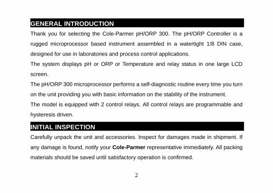
GENERAL INTRODUCTION
Thank you for selecting the Cole-Parmer pH/ORP 300. The pH/ORP Controller is a
rugged microprocessor based instrument assembled in a watertight 1/8 DIN case,
designed for use in laboratories and process control applications.
The system displays pH or ORP or Temperature and relay status in one large LCD
screen.
The pH/ORP 300 microprocessor performs a self-diagnostic routine every time you turn
on the unit providing you with basic information on the stability of the instrument.
The model is equipped with 2 control relays. All control relays are programmable and
hysteresis driven.
INITIAL INSPECTION
Carefully unpack the unit and accessories. Inspect for damages made in shipment. If
any damage is found, notify your Cole-Parmer representative immediately. All packing
materials should be saved until satisfactory operation is confirmed.

3
USING THE pH/ORP 300ERVIEW
A. Mounting Procedure
PANEL CUTOUT DIMENSIONS
45.0 1.772"
92.0 3.622"0.813 0.032
0.61
0.0240.00
0.000
0.000 0.000± ±
±±
DRAWING 1
1. Make a cutout on any panel, with a
thickness of 1/16 inch (1.5mm) to
3/8 inch (9.5mm). Refer to
DRAWING 1.
Mounting Brackets
DRAWING 2
2. Remove the mounting assembly
from the controller and insert the
controller into the cutout. Refer to
DRAWING 2.

4
Panel Mounting brackets
DRAWING 3
3. Replace the mounting bracket
assembly onto the controller and
secure the controller to the
mounting panel. Refer to
DRAWING 3.
【Note】:
If the equipment is used in a manner not specified by the manufacturer, the protection
provided by the equipment may be impaired.

5
B. Front Panel
The front panel consists of a 4-digit LCD display and 4 keys.
HI1
STAND SLOPE 7.00 ATC
pH
ENTER
MODE
1. [ MODE ] key:
1a. In the Measure mode, this key will switch the display in sequence from pH,
Temperature, ORP absolute mV, ORP relative mV and back to pH again.
1b. In the Calibration/Setting mode, pressing this key for three seconds will
move you back to the previous parameter in the case when recalibration / resetting
is required.

6
2. [ UP ] key:
2a. In the Calibration mode, pressing this key will show the next possible option.
In the Setting mode, pressing this key will show the next possible option and
increases the numeral increment.
2b. In the Measure mode, pressing this key and [ENTER] key at the same time,
the unit will enter the Calibration mode.
3. [ DOWN ] key:
3a. In the Calibration mode, pressing this key will show the next possible option.
In the Setting mode, pressing this key will show the next possible option and
decreases the numeral increment.
3b. In the Measure mode, pressing this key and [ENTER] key at the same time,
the unit will enter the Setting mode.
4. [ ENTER ] key:
In any mode where the user can change the settings, pressing this key will save
the new settings. If no change has been made then pressing this key will just move

7
the user to the next setting.
C. LCD screen
HI1 LOW2
STAND SLOPERmV
CAL
6.86 7.00 ATC MAN
pHHI2 LOW1
1 2 3 4 5 6
13121110987
C
1. Major LCD display.
2. CAL – This icon will be displayed if the meter is in the Calibration/Setting mode.
3. HI1 & LOW1 – These icons, when displayed, indicate relay action and relay
number.

8
4. HI2 & LOW2 –These icons, when displayed, indicate relay action and relay
number.
5. ℃ – Temperature and unit display.
6. pH – Unit indicator.
7. STAND – This icon will blink before Buffer 1 calibration. The icon will stay on while
Buffer 1 is being calibrated.
8. SLOPE – This icon will blink before Buffer 2 calibration. The icon will stay on while
Buffer 2 is being calibrated.
9. 6.86 – The 6.86 buffer group: 6.86, 4.00, 9.18.
10. 7.00 – The 7.00 buffer group: 7.00, 4.01, 10.01.
11. ATC –This icon will be displayed when a temperature probe is connected.
12. MAN –This icon will be displayed when a temperature probe is not connected.
13. RmV – Unit indicator.

9
D. Rear connectors
L N E
+V -V 10k TH Pt 1000
100~230VAC Rel 1 Rel2
RFFINPUT GND
* Specify “L’ = “Live Lead” 100 to 230 VAC Volts and “N” = “Neutral Lead”
1. Connect the AC line to the rear of the instrument. The model pH/ORP300 can be
used with 100~240V AC at 50/60 HZ. Make sure the EARTH connector is
connected to the earth lead of the AC power line.
2. Connect the proper load to the output relays. Make sure that the load does not
exceed the relay rating, 5 Amp at 115VAC and 2.5 Amp at 230 VAC.

10
3. V+ (5VDC) and V- (5VDC) output to provide excitation voltage for pH/ORP
pre-amplifier only.
【Note】:
(1) Make sure that the power is unplugged before wiring your probes, relay etc.
(2) Make sure you connect the AC power cord to the correct AC terminals. Connecting
incorrectly may damage the unit permanently.
E. Measure mode
Turning on the unit will always display the Measure mode. This instrument is designed
to provide 4 distinct measurements:
7.00 ATC
pH
ATC
C
mV
RmV
MODE MODE
MODEMODE
11
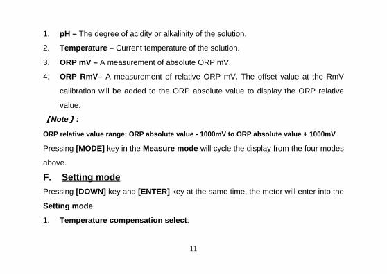
1. pH – The degree of acidity or alkalinity of the solution.
2. Temperature – Current temperature of the solution.
3. ORP mV – A measurement of absolute ORP mV.
4. ORP RmV– A measurement of relative ORP mV. The offset value at the RmV
calibration will be added to the ORP absolute value to display the ORP relative
value.
【Note】:
ORP relative value range: ORP absolute value - 1000mV to ORP absolute value + 1000mV
Pressing [MODE] key in the Measure mode will cycle the display from the four modes
above.
F. Setting mode
Pressing [DOWN] key and [ENTER] key at the same time, the meter will enter into the
Setting mode.
1. Temperature compensation select:

12
+ENTER
ENTER ENTER ENTER
pH buffer 1 select
CAL
ATC
CAL
ATC
CAL
MAN
Pressing [UP] key or [DOWN] key in this screen will cycle the display from 01
(Thermistor: 10k ohm)、02 (Resistor: PT1000)、03 (Manual) modes above.
Select the preferred temperature compensation mode, press [ENTER] key to save,
and enter the next setting screen.
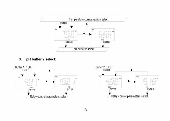
2. pH buffer 1 select:
Pressing [UP] key or [DOWN] key in this screen will cycle the display from 7.00、
6.86 buffer above.
Select the preferred buffer, press [ENTER] key to save, and enter the next setting
screen.
13
Temperature compensation select
pH buffer 2 select
ENTER
ENTER ENTER
CAL
6.86
pH
CAL
7.00
pH
3. pH buffer 2 select:
Buffer 1 7.00
Relay control parameters select
ENTER
CAL
7.00
pHCAL
7.00
pH
ENTER ENTER
Buffer 2 6.86
Relay control parameters select
ENTER
ENTER ENTER
CAL
6.86
pHCAL
6.86
pH

14
Pressing [UP] key or [DOWN] key in this screen will cycle the display from 4.01、
10.01 (or 4.00、9.18) buffer above.
Select the preferred buffer, press [ENTER] key to save, and enter the next setting
screen.
【Note】: The pH buffer 2 is either 4.01 or 10.01 if select 7.00 buffer at pH buffer 1
select screen. The pH buffer 2 is either 4.00 or 9.18 if select 6.86 buffer at pH
buffer 1 select screen.
4. Relay control parameters select:
Buffer 2 select
Relay 1 HI/LOW select
ENTER
ENTER ENTER ENTER
RmV
CALCALpH
mV
CAL

15
Pressing [UP] key or [DOWN] key in this screen will cycle the display from pH、
ORP mV、ORP RmV modes above.
Select the preferred mode, press [ENTER] key to save, and enter the next setting
screen.
【Note】: The relay will work with the choice of parameters.
5. Relay 1 High / Low select:
Pressing [UP] key or [DOWN] key in this screen will cycle the display from HI、
LOW modes above. Select the preferred mode, press [ENTER] key to save, and
enter the next setting screen.
Relay control paramelers select
Relay 1 set point value
ENTER
ENTER ENTER
HI1CAL CAL LOW1

16
【Note】: See “I. Controlling the relays ” page.
6. Relay 1 set point value:
Pressing [UP] key or [DOWN] key in this screen to adjust
the value, press [ENTER] key to save, and enter the next
setting screen.
7. Relay 1 hysteresis value:
Pressing [UP] key or [DOWN] key in this screen to adjust
the value, press [ENTER] key to save, and enter the next
setting screen.
Relay 1 HI/LOW select
Relay 1 hysteresis value
ENTER
ENTER
CALpH
Relay 2 HI/LOW select
ENTER
ENTER
CAL
Relay 1 set point value
pH

17
8. Relay 2 High / Low select:
Same as “Relay 1 work way select”
9. Relay 2 set point value:
Same as “Relay 1 set point value”
10. Relay 2 hysteresis value:
Same as “Relay 1 hysteresis value”
G. pH Calibration mode
The model uses 2-point calibration for pH. The first point must be 6.86/7.00, and the
second point can either be 4.00/4.01 or 9.18/ 10.01.
In the pH Measure mode, pressing [UP] key and [ENTER] key at the same time to
allow the meter to go to the pH Calibration mode.

18
1. Buffer 1 (STAND) calibration:
Buffer 2 calibration
+ENTER ENTER
STAND
CAL
7.00
pH
STAND SLOPE 7.00
pHHI2
STAND
CAL
7.00
pH
Enter into the pH calibration mode, the “STAND” icon will flash, the unit is ready to
be standardized at the first buffer. Rinse the pH and ATC/Temp probes in distilled
water and immerse them in the first buffer solution (either 7.00 or 6.86). Allow
temperature reading to stabilize, then press “ENTER” key to calibrate. The “pH”
icon will flash until the unit detects a stable reading. Once the unit calibrates the
first point, the “SLOPE” icon will flash. The unit is ready to be sloped at the
second buffer.

19
2. Buffer 2 (SLOPE) calibration:
Rinse the pH and ATC/Temp probe in distilled water and immerse them in the
second buffer solution (either 4.00/4.01 or 9.18/10.01). Allow temperature reading
to stabilize, then press “ENTER” key to calibrate. The “pH” icon will flash until the
unit detects a stable reading. Once the unit calibrates the second point and the
unit will automatically exit the calibration mode and goes to the pH Measure
mode. Dual point calibration is complete.
【Note】: In the Setting mode (1. Temperature compensation select), select
03 (Manual temperature compensation mode) if no temperature probe is being
used. Press the [UP] key or [DOWN] key in the Manual temperature
compensation mode to adjust the value to that of the test solution temperature.
ENTER
Buffer 1 calibration
Measure modeSTAND SLOPE
CAL
7.00
pH
STAND SLOPE
CAL
7.00
pH

20
Then calibrate buffer 1 and buffer 2.
H. RmV Calibration mode
RmV normal mode
orCAL
RmV
CAL
RmV RmV
+ENTER
The model 3621 uses 1-point calibration for RmV. In the RmV Measure mode,
pressing [UP] key and [ENTER] key at the same time, the meter will enter into RmV
calibration mode.
Rinse the ORP probe in distilled water and immerse it in the ORP standard solution,
then press [UP] or [DOWN] key to adjust the ORP value to that the ORP standard.
Press [ENTER] key to save. The unit beeps to indicate a successful calibration.
Calibration is now complete and the unit will automatically switch to the ORP relative
mV Measure mode.

21
【Note】: When the ORP absolute mV reading is off, recalibrate RmV value.
I. Controlling the relays
1. Isolation voltage:
The maximum isolation voltage of the relay output contacts is 1500 VDC. The
voltage differential between the relay output contacts and the load should not
exceed 1500 VDC.
2. Output load:
The current through the relay output contacts should not exceed 5 Amp at 115
VAC and 2.5 Amp at 230 VAC in order not to cause permanent damage to the
relay contacts. This rating is specified for resistive loads only.
3. Relay action, relay set point and hysteresis value:
Relay Action Effective RELAY-ON Set Point Effective RELAY-OFF Set Point
HI S.P. + (1/2 H.V) S.P. – (1/2 H.V)
LOW S.P. – (1/2 H.V) S.P. + (1/2 H.V.)
S.P. = Relay Set point H.V. = Hysteresis value (Dead Band)

22
If the relay action is set to HIGH, the relay will turn ON at (Set Point +1/2
Hysteresis ), and will turn OFF at (Set Point -1/2 Hysteresis ).
If the relay action is set to LOW, the relay will turn ON at (Set Point -1/2
Hysteresis ), and will turn OFF at (Set Point +1/2 Hysteresis ).
There are two Independent relays the user can bind to the pH, ABSOLUTE mV or
RELATIVE mV mode. The user can only bind the two relays to one reading mode
at a time. The user can change this anytime by changing option at the setting
mode.
【Note】:
1. The ideal set point range for pH is 0.00 to 16.00 pH.
2. The ideal set point range for absolute mV is –2000 to 2000 mV.
3. The ideal set point range of for relative mV is -3000 to 3000 mV.

23
ERROR DISPLAY AND TROUBLESHOOTING ERVIEW
pH/ORP
Display
Temperature
Display Display Mode
Possible cause(s)
[Action(s)]
"OvEr" -10.0~120.0
°C
pH measure mode pH > 16.00pH
[Recalibrate]
“Undr” -10.0~120.0
°C
pH measure mode pH < -2.00pH
[Recalibrate]
"OvEr" "OvEr" pH measure mode a. Temperature > 120.0°C.
[Bring buffer solution to lower
temperature.]
[Replace temperature probe.]
b. No temperature sensor.
[Adjust the manual temperature to
-10~120°C.]

24
"OvEr" “Undr” pH measure mode a. Temperature < -10.0°C.
[Bring buffer solution to higher
temperature.]
[Replace temperature probe.]
b. No temperature sensor.
[Adjust the manual temperature to
-10~120°C.]
"OvEr" Temperature
reading
Absolute ORP mV
or relative ORP
Absolute ORP mV > +1999 mV
[Bring solution to a lower ORP
reading]
"Undr" Temperature
reading
Absolute ORP mV
or relative ORP
Absolute ORP mV < -1999 mV
[Bring solution to a higher ORP
reading]

25
ORP
reading
"OvEr" Absolute ORP mV
or relative ORP
a. Temperature > 120.0°C.
[Bring buffer solution to lower
temperature.]
[Replace temperature probe.]
b. No temperature sensor.
[Adjust the manual temperature to
-10~120°C.]
ORP
reading
"Uder" Absolute ORP mV
or relative ORP
a. Temperature < -10.0°C.
[Bring buffer solution to higher
temperature.]
[Replace temperature probe.]
b. No temperature sensor.
[Adjust the manual temperature to
-10~120°C.]
26
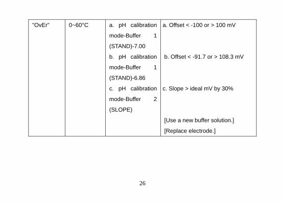
"OvEr" 0~60°C a. pH calibration
mode-Buffer 1
(STAND)-7.00
b. pH calibration
mode-Buffer 1
(STAND)-6.86
c. pH calibration
mode-Buffer 2
(SLOPE)
a. Offset < -100 or > 100 mV
b. Offset < -91.7 or > 108.3 mV
c. Slope > ideal mV by 30%
[Use a new buffer solution.]
[Replace electrode.]

27
pH BUFFERS
The temperature characteristics of pH calibration buffers pH4.00, pH4.01, pH6.86,
pH7.00, pH9.18 & pH10.01 are stored inside the instrument. The buffers used to
calibrate the instrument must exhibit the same temperature characteristics as the
stored values.
°C 4.00 6.86 9.18 4.01 7.00 10.01
0 4.01 6.98 9.46 4.01 7.11 10.32
5 4.00 6.95 9.39 4.01 7.08 10.25
10 4.00 6.92 9.33 4.00 7.06 10.18
15 4.00 6.90 9.28 4.00 7.03 10.12
20 4.00 6.88 9.23 4.00 7.01 10.06
25 4.00 6.86 9.18 4.01 7.00 10.01
30 4.01 6.85 9.14 4.01 6.98 9.97
35 4.02 6.84 9.10 4.02 6.98 9.93

28
40 4.03 6.84 9.07 4.03 6.97 9.89
45 4.04 6.83 9.04 4.04 6.97 9.86
50 4.06 6.83 9.02 4.06 6.97 9.83
55 4.07 6.83 8.99 4.08 6.97 9.80
60 4.09 6.84 8.97 4.10 6.98 9.78
【Note】: The actual reading of the instrument can differ from the values shown by
±0.01 pH.
SPECIFICATIONS
Mode Range Resolution Accuracy
pH -2.00 to 16.00 pH 0.01 pH ±0.1% ± 1 digit
ORP Absolute mV -1999 to 1999 mV 1 mV ±0.1% ± 1 digit
ORP Relative mV -2999 to 2999 mV 1 mV ±0.1% ± 1 digit
Temperature -10.0 to 120.0 °C 0.1 °C ±0.3 °C

29
pH:
Recognized pH buffers US (4.01, 7.00, 10.01) or NIST (4.00,
6.86, 9.18)
pH Temperature compensation Manual/Auto -10.0°C to 120.0 °C
pH Buffer Temperature range 0.0°C to 60.0 °C
pH Electrode Offset recognition 100 mV at pH 7.00
+108.3 mV/-91.7 mV at pH 6.86
pH Electrode Slope recognition 30% at pH 4.00, 4.01, 9.18, 10.01
Input impedance >1012
Calibration end point sensing Yes
Temperature:
Temperature sensor Thermistor: 10k ohm at 25 °C,
(User selectable) Resistor ( PT1000) or Manual
Controller:
Control type Two ON/OFF control

30
Relay output(Resistive load only) 5A at 115VAC or 2.5A at 220VAC
General:
Keys Audio feedback in all keys
Power: 100VAC to 240VAC , 50/60Hz
Ambient Temperature range 0.0 to 50.0 °C
Case IP65, 1/8DIN case, depth 90mm
Weight 290 g
WARRANTY
The Cole-Parmer Instrument Company warrants this product to be free from
significant deviations in material and workmanship for a period of one year. If repair
or adjustment is necessary and has not been the result of abuse or misuse, within the
twelve month period, please return, freight-prepaid, and correction will be made
without charge (see note on return of items). Cole-Parmer alone will determine if the
product problem is due to deviations or customer misuse.

31
Out of warranty products will be repaired for a nominal charge.
RETURN OF ITEMS
Authorization must be obtained from our Customer Service Department before
returning items for any reason. When applying for authorization, please include data
regarding the reason the items are to be returned. A restocking charge will be made
on all unauthorized returns.
For your protection, items being returned must be carefully packed to prevent
damage in shipment and insured against possible damage or loss. Cole-Parmer will
not be responsible for damage resulting from careless or insufficient packing.
【Note】 : The Cole-Parmer Instrument Company reserves the right to make
improvements in design, construction and appearance of our products without notice.
We stand behind our products. For additional information on our products, warranty, or returns please contact our office or visit our website listed on front page.

32
英文说明书
机型:pH/ORP300 编制人:汪蕾 日期:2012-09-10
文件编号:KpH/ORP300-01 修改人:汪蕾 日期:2012-09-10
版本:01 核准人: 日期: