cold-shot operating instructions › app › uploads › 2018 › 04 ›...
TRANSCRIPT

Cold-Shot™
Operating Instructions
For 1/8” through 2” metal and plastic lines (10mm—60mm)
Your Cold-Shot is designed to give you
years of trouble-free, profitable service.
However, no machine is better than its op-
erator.
Read, understand and follow all safety
warnings and instructions provided with
the product. Failure to follow the warnings
and instructions may result in electric
shock and/or serious injury. Save all warn-
ings and instructions for future reference.
SAVE THESE INSTRUCTIONS!
M
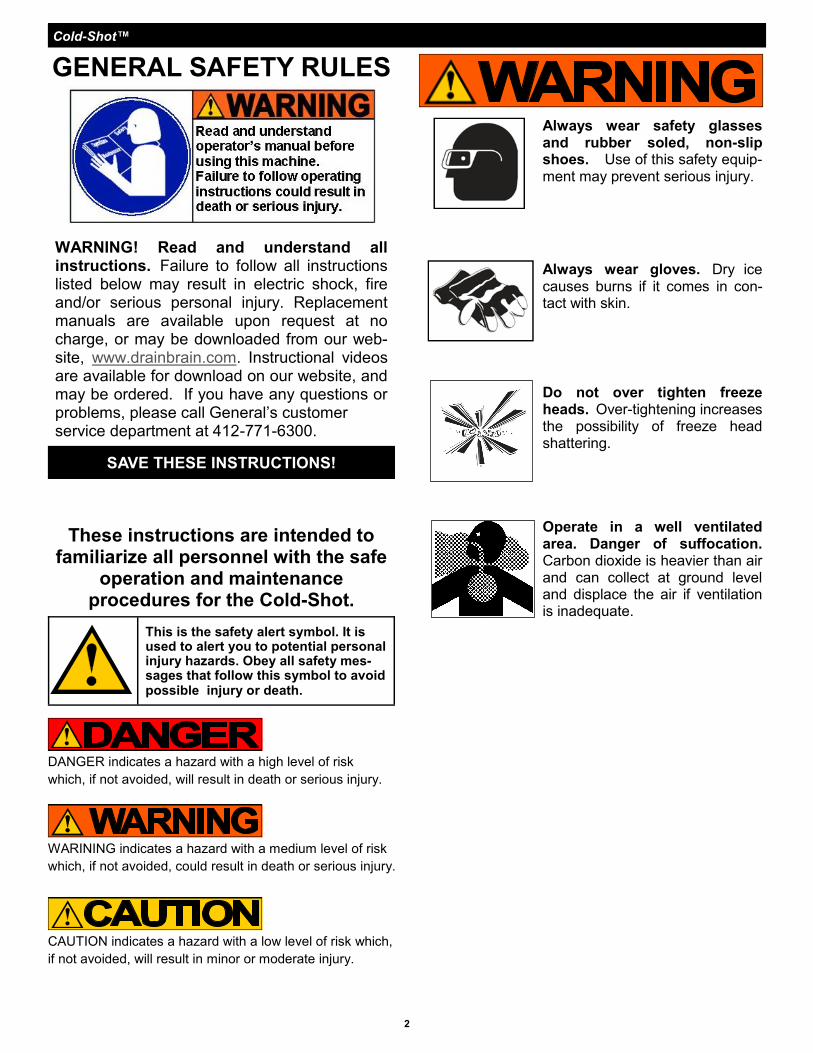
WARNING! Read and understand all instructions. Failure to follow all instructions listed below may result in electric shock, fire and/or serious personal injury. Replacement manuals are available upon request at no charge, or may be downloaded from our web-site, www.drainbrain.com. Instructional videos are available for download on our website, and may be ordered. If you have any questions or problems, please call General’s customer service department at 412-771-6300.
SAVE THESE INSTRUCTIONS!
GENERAL SAFETY RULES
Cold-Shot™
Operate in a well ventilated area. Danger of suffocation. Carbon dioxide is heavier than air and can collect at ground level and displace the air if ventilation is inadequate.
Always wear gloves. Dry ice causes burns if it comes in con-tact with skin.
Always wear safety glasses and rubber soled, non-slip shoes. Use of this safety equip-ment may prevent serious injury.
These instructions are intended to familiarize all personnel with the safe
operation and maintenance procedures for the Cold-Shot.
DANGER indicates a hazard with a high level of risk
which, if not avoided, will result in death or serious injury.
WARINING indicates a hazard with a medium level of risk
which, if not avoided, could result in death or serious injury.
CAUTION indicates a hazard with a low level of risk which,
if not avoided, will result in minor or moderate injury.
This is the safety alert symbol. It is used to alert you to potential personal injury hazards. Obey all safety mes-sages that follow this symbol to avoid possible injury or death.
Do not over tighten freeze heads. Over-tightening increases the possibility of freeze head shattering.
2

Cold-Shot™
3
GENERAL SAFETY RULES Work Area
1. Keep work area clean and well lit. Cluttered benches and dark areas invite accidents.
2. Do not operate within two feet of open flame. Heat source within close range of the metal pipe could melt ice plug, causing catastrophic failure and severe water damage
3. Keep bystanders, children, and visitors away while operating. Dry ice causes burns if it comes in contact with skin.
Personal Safety 1. Work only in a well ventilated area. Carbon diox-
ide is non-toxic and non-flammable, but is heavier than air and can collect at ground level, displacing the air if ventilation is inadequate, giving rise to the danger of suffocation.
2. Stay alert, watch what you are doing and use common sense when operating a tool. Do not use tool while tired or under the influence of drugs, alcohol, or medication. A moment of inattention while operating may result in serious personal injury.
2. Dress properly. Do not wear loose clothing or jewelry. Contain long hair. Keep your hair, cloth-ing, and gloves away from moving parts. Loose clothes, jewelry, or long hair can be caught in moving parts.
3. Do not overreach. Keep proper footing and bal-ance at all times. Proper footing and balance en-ables better control of the tool in unexpected situa-tions.
4. Use safety equipment. Always wear eye protec-tion and rubber gloves. Dust mask, non-skid safety shoes, hard hat, or hearing protection must be used for appropriate conditions.
5. Avoid dangerous flammable liquids or gases.
6. Observe all safety instructions provided by the
carbon dioxide supply company.
7. Store idle tools out of reach of children and other untrained persons. Tools are dangerous in the hands of untrained users.
8. Maintain tools with care. Replace worn parts as early as possible.
9. Inspect occasionally for any condition that may affect the tool’s operation. If damaged, have the tool serviced before using. Many accidents are caused by poorly maintained tools.
10. Only use parts and accessories that are recom-mended by the manufacturer for your model. Parts and accessories that may be suitable for one tool may become hazardous when used on another tool.
11. Only use the Cold-Shot for the purpose for which it was intended. Any unauthorized use or modifica-tions of the Cold-Shot are prohibited for safety rea-sons.
SPECIFIC SAFETY RULES 1. Wear eye protection, safety glasses, or goggles.
Use of this safety equipment may prevent serious eye injury.
2. Wear rubber gloves. Use of this safety equipment may prevent serious freeze injury from extreme cold.
3. Only use this tool in the application for which it was designed. Follow the instructions on the proper use of the machine. Other uses or modifica-tion of the Cold-Shot for other applications may in-crease risk of injury.
4. Never hit a chilled freeze head with a hammer or other tool. A sharp blow will cause the freeze heads to shatter.
5. Do not over tighten freeze heads. Gas must be allowed to escape. Over tightening increases the possibility of freeze heads shattering.
6. Inspect freeze heads for cracks or other signs of wear before each use. Replace at the first sign of deterioration.
Tool Use and Care 1. Only use carbon dioxide (CO2) cylinders
equipped with a dip tube. Carbon dioxide must be drawn from the cylinder in a liquid state in order to produce dry ice.
2. Do not connect a pressure reducer to the cylin-
der.
3. Keep the cylinder in an upright position and se-
cure it to prevent it from falling over.
4. Do not completely empty the cylinder.
5. Do not interfere with nozzles, freeze heads or
valves, including cylinder valves.
6. Use clamps or other practical way to secure and support the work piece to a stable platform. Hold-ing the work by hand or against your body may cause serious personal injury.
Service 1. Tool service must be performed only by qualified
repair personnel. Service or maintenance per-formed by unqualified repair personnel could result in injury.
2. When servicing a tool, use only identical replace-ment parts. Follow instructions in the Mainte-nance section of this manual. Use of unauthorized parts or failure to follow Maintenance Instructions may create a risk injury.
Cold-Shot™
4
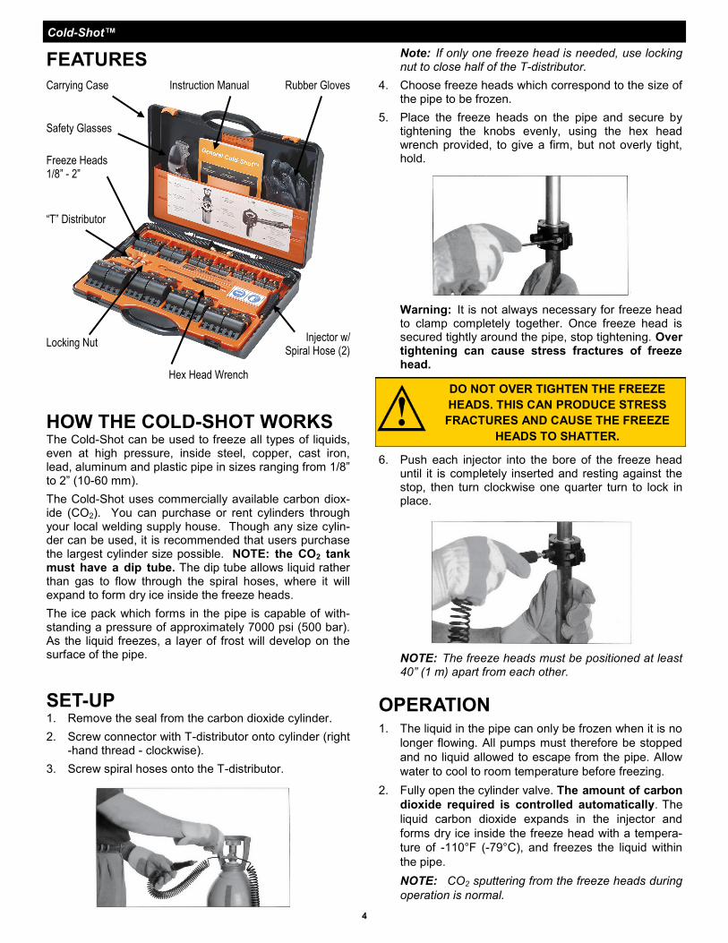
FEATURES
Carrying Case
Safety Glasses
Freeze Heads 1/8” - 2”
“T” Distributor
Locking Nut
Rubber Gloves
Injector w/Spiral Hose (2)
Hex Head Wrench
Instruction Manual
HOW THE COLD-SHOT WORKS The Cold-Shot can be used to freeze all types of liquids, even at high pressure, inside steel, copper, cast iron, lead, aluminum and plastic pipe in sizes ranging from 1/8” to 2” (10-60 mm).
The Cold-Shot uses commercially available carbon diox-ide (CO2). You can purchase or rent cylinders through your local welding supply house. Though any size cylin-der can be used, it is recommended that users purchase the largest cylinder size possible. NOTE: the CO2 tank must have a dip tube. The dip tube allows liquid rather than gas to flow through the spiral hoses, where it will expand to form dry ice inside the freeze heads.
The ice pack which forms in the pipe is capable of with-standing a pressure of approximately 7000 psi (500 bar). As the liquid freezes, a layer of frost will develop on the surface of the pipe.
SET-UP 1. Remove the seal from the carbon dioxide cylinder.
2. Screw connector with T-distributor onto cylinder (right-hand thread - clockwise).
3. Screw spiral hoses onto the T-distributor.
Note: If only one freeze head is needed, use locking nut to close half of the T-distributor.
4. Choose freeze heads which correspond to the size of the pipe to be frozen.
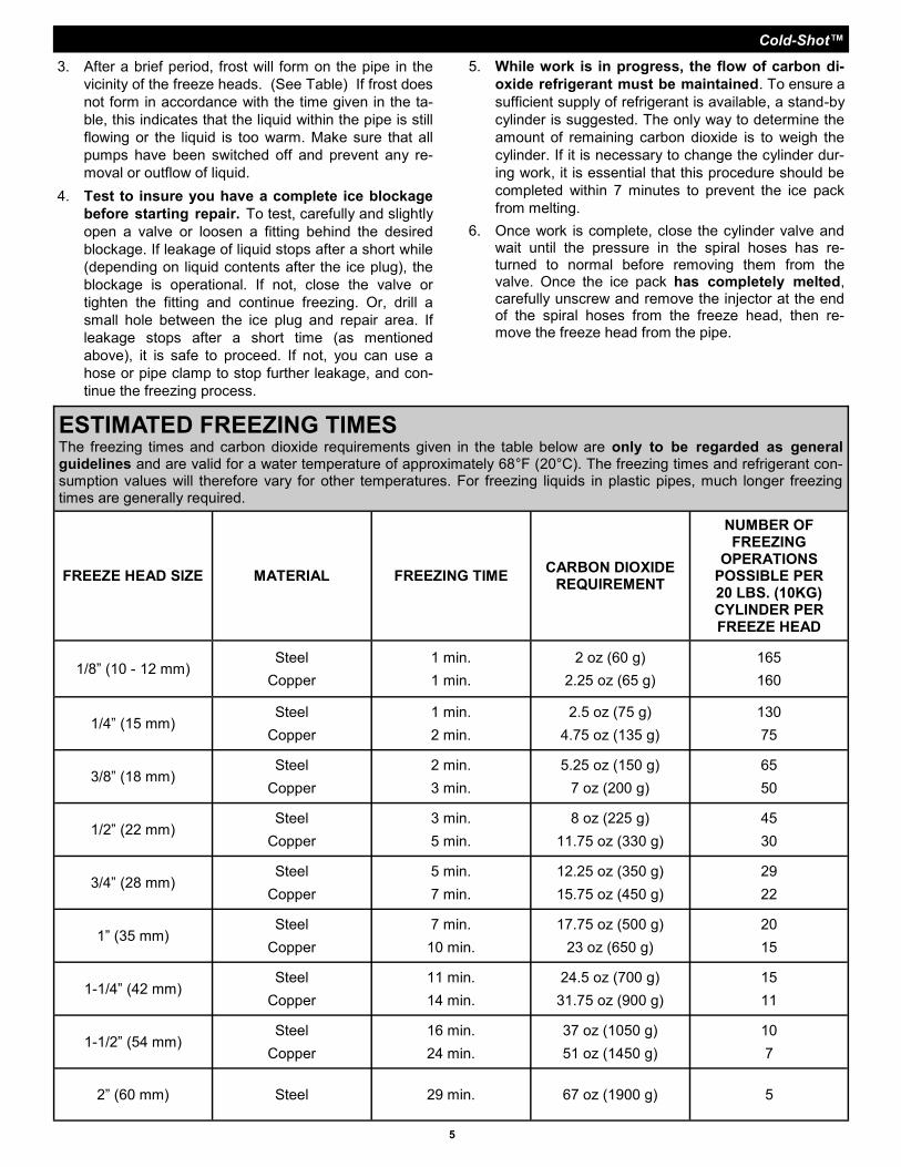
5. Place the freeze heads on the pipe and secure by tightening the knobs evenly, using the hex head wrench provided, to give a firm, but not overly tight, hold.
6. Push each injector into the bore of the freeze head until it is completely inserted and resting against the stop, then turn clockwise one quarter turn to lock in place.
OPERATION 1. The liquid in the pipe can only be frozen when it is no
longer flowing. All pumps must therefore be stopped
and no liquid allowed to escape from the pipe. Allow
water to cool to room temperature before freezing.
2. Fully open the cylinder valve. The amount of carbon
dioxide required is controlled automatically. The
liquid carbon dioxide expands in the injector and
forms dry ice inside the freeze head with a tempera-
ture of -110°F (-79°C), and freezes the liquid within
the pipe.
NOTE: CO2 sputtering from the freeze heads during
operation is normal.
Warning: It is not always necessary for freeze head to clamp completely together. Once freeze head is secured tightly around the pipe, stop tightening. Over tightening can cause stress fractures of freeze head.
NOTE: The freeze heads must be positioned at least 40” (1 m) apart from each other.
DO NOT OVER TIGHTEN THE FREEZE
HEADS. THIS CAN PRODUCE STRESS
FRACTURES AND CAUSE THE FREEZE
HEADS TO SHATTER.
Cold-Shot™
5
5. While work is in progress, the flow of carbon di-
oxide refrigerant must be maintained. To ensure a
sufficient supply of refrigerant is available, a stand-by
cylinder is suggested. The only way to determine the
amount of remaining carbon dioxide is to weigh the
cylinder. If it is necessary to change the cylinder dur-
ing work, it is essential that this procedure should be
completed within 7 minutes to prevent the ice pack
from melting.
6. Once work is complete, close the cylinder valve and wait until the pressure in the spiral hoses has re-turned to normal before removing them from the valve. Once the ice pack has completely melted, carefully unscrew and remove the injector at the end of the spiral hoses from the freeze head, then re-move the freeze head from the pipe.
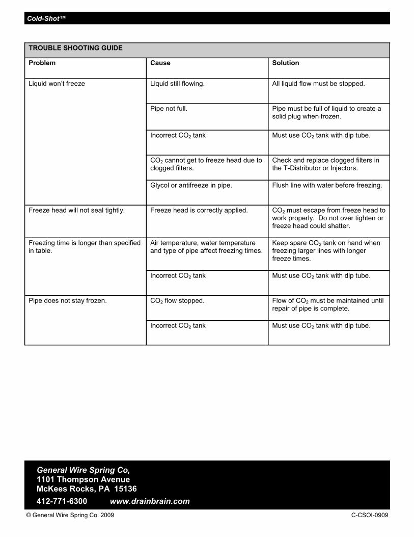
ESTIMATED FREEZING TIMES The freezing times and carbon dioxide requirements given in the table below are only to be regarded as general guidelines and are valid for a water temperature of approximately 68°F (20°C). The freezing times and refrigerant con-sumption values will therefore vary for other temperatures. For freezing liquids in plastic pipes, much longer freezing times are generally required.
FREEZE HEAD SIZE MATERIAL FREEZING TIME CARBON DIOXIDE
REQUIREMENT
NUMBER OF FREEZING
OPERATIONS POSSIBLE PER 20 LBS. (10KG) CYLINDER PER FREEZE HEAD
1/8” (10 - 12 mm) Steel
Copper
1 min.
1 min.
2 oz (60 g)
2.25 oz (65 g)
165
160
1/4” (15 mm) Steel
Copper
1 min.
2 min.
2.5 oz (75 g)
4.75 oz (135 g)
130
75
3/8” (18 mm) Steel
Copper
2 min.
3 min.
5.25 oz (150 g)
7 oz (200 g)
65
50
1/2” (22 mm) Steel
Copper
3 min.
5 min.
8 oz (225 g)
11.75 oz (330 g)
45
30
3/4” (28 mm) Steel
Copper
5 min.
7 min.
12.25 oz (350 g)
15.75 oz (450 g)
29
22
1” (35 mm) Steel
Copper
7 min.
10 min.
17.75 oz (500 g)
23 oz (650 g)
20
15
1-1/4” (42 mm) Steel
Copper
11 min.
14 min.
24.5 oz (700 g)
31.75 oz (900 g)
15
11
1-1/2” (54 mm) Steel
Copper
16 min.
24 min.
37 oz (1050 g)
51 oz (1450 g)
10
7
2” (60 mm) Steel 29 min. 67 oz (1900 g) 5
3. After a brief period, frost will form on the pipe in the
vicinity of the freeze heads. (See Table) If frost does
not form in accordance with the time given in the ta-
ble, this indicates that the liquid within the pipe is still
flowing or the liquid is too warm. Make sure that all
pumps have been switched off and prevent any re-
moval or outflow of liquid.
4. Test to insure you have a complete ice blockage
before starting repair. To test, carefully and slightly
open a valve or loosen a fitting behind the desired
blockage. If leakage of liquid stops after a short while
(depending on liquid contents after the ice plug), the
blockage is operational. If not, close the valve or
tighten the fitting and continue freezing. Or, drill a
small hole between the ice plug and repair area. If
leakage stops after a short time (as mentioned
above), it is safe to proceed. If not, you can use a
hose or pipe clamp to stop further leakage, and con-
tinue the freezing process.
Cold-Shot™
General Wire Spring Co, 1101 Thompson Avenue McKees Rocks, PA 15136
412-771-6300 www.drainbrain.com
© General Wire Spring Co. 2009 C-CSOI-0909
TROUBLE SHOOTING GUIDE
Problem Cause Solution
Liquid won’t freeze Liquid still flowing. All liquid flow must be stopped.
Pipe not full. Pipe must be full of liquid to create a solid plug when frozen.
Incorrect CO2 tank Must use CO2 tank with dip tube.
CO2 cannot get to freeze head due to clogged filters.
Check and replace clogged filters in the T-Distributor or Injectors.
Glycol or antifreeze in pipe. Flush line with water before freezing.
Freeze head will not seal tightly. Freeze head is correctly applied. CO2 must escape from freeze head to work properly. Do not over tighten or freeze head could shatter.
Freezing time is longer than specified in table.
Air temperature, water temperature and type of pipe affect freezing times.
Keep spare CO2 tank on hand when freezing larger lines with longer freeze times.
Incorrect CO2 tank Must use CO2 tank with dip tube.
Pipe does not stay frozen. CO2 flow stopped. Flow of CO2 must be maintained until repair of pipe is complete.
Incorrect CO2 tank Must use CO2 tank with dip tube.