cold chemical lamination of ceramic green tapes -...
TRANSCRIPT
This is the author accepted version of the following article: Jurkow, Dominik, Henryk Roguszczak, and
Leszek Golonka. "Cold chemical lamination of ceramic green tapes." Journal of the European Ceramic Society 29.4 (2009): 703-709., which has been published in final form at
http://www.sciencedirect.com/science/article/pii/S0955221908004068
1
Cold Chemical Lamination of Ceramic Green Tapes
Dominik Jurków, Henryk Roguszczak, Leszek Golonka
Wroclaw University of Technology, Faculty of Microsystem Electronics and Photonics
Wybrzeze Wyspianskiego 27, 50-370 Wroclaw, Poland
Abstract
The Cold Chemical Lamination (CCL) is a new technique of bonding ceramic green tapes
into one 3D structure. Instead of a standard thermo-compression method, new
solvent-based lamination is presented. A film of a special chemical agent is put on the
green tape surface. The solvent melts the surface. Then the tapes are stacked. The bonding
of the green tapes is made at a room temperature. The new method is used for joining green
tapes of the Low Temperature Co-fired Ceramics (LTCC). A quality of the bonding
depends on the solvent type. The Cold Chemical Lamination is examined on two types of
the LTCC tapes: DuPont 943 and DuPont 951. Six types of the solvents are analyzed in the
paper. The bonding quality and geometry of the test structures are examined. The
lamination quality is investigated by the Scanning Electron Microscope.
Key words: Joining, Pressing, Lamination, LTCC
1. Introduction
The Low Temperature Cofired Ceramic (LTCC) technique is well known for last two
decades. The market of the LTCC devices is still growing. It is caused by the advantages
of the LTCC. It combines advantages of a Thick Film and a High Temperature Co-fired
Ceramic (HTCC) techniques. The LTCC technological process consists of: tape casting,
shapes cutting in the green tape ceramic, screen printing, lamination and cofiring. All these

This is the author accepted version of the following article: Jurkow, Dominik, Henryk Roguszczak, and
Leszek Golonka. "Cold chemical lamination of ceramic green tapes." Journal of the European Ceramic Society 29.4 (2009): 703-709., which has been published in final form at
http://www.sciencedirect.com/science/article/pii/S0955221908004068
2
steps are important to achieve good quality of the final structure. However, lamination of
the low temperature co-fired ceramic is one of the most important technological steps
during a manufacturing of sensors 1-4
, channels 2,4,5
, microfluidic systems 6, chambers,
reactors 2,7
, cooling systems 4,5
, micropumps 4, microwave filters
8, miniaturize antennas
8
and others 3D devices made in the LTCC technique. A standard thermo-compression
lamination is the most common method of bonding green tapes. The bonding is created at
temperature 50 to 80 °C at high pressure above 5 MPa, for 2 to 15 minutes. During this
process the LTCC tapes are getting soft and are joining together. The method has several
advantages. Many layers can be bonded in one package. The bonding is strong. However,
there is one important problem. High pressure and temperature cause deformation of a
manufacturing structure 5. The problem can be reduced by using fugitive phase (sacrificial
material) intended to disappear during a cofiring process 9,10
. The first alternative method of
bonding LTCC tapes was shown by Roosen 11-13
. He called it Cold Low Pressure
Lamination (CLPL). It is based on temporary gluing step. The LTCC green tapes are
bonded together by two side adhesive tape. During the burning process the adhesive tape is
melting and diffusing into the LTCC tapes. The method has many advantages: the bond is
made at room temperature at low pressure, the chambers and channels are not deformed
during the process. However, it has also disadvantages. The close chambers can not be
done. The laminated stack might crack during the burning process. It is common for
structures consists above 10 tapes with close chamber. The effect might be caused by
increasing of pressure in the chamber during firing. The method can be used for making
open chambers and channels.
Another adhesive-method was presented by Rocha14
. The layers are bonded by adhesive
liquid. There are used several different types of such substations (e. g. natural honey). The
LTCC tapes are covered by the organic liquid film. Then they are stacked together. The
liquid glues the layers. The temporary gluing process is realized at very low pressure at
room temperature. The bonding achieve by the method is good. The chambers are not
deformed. The non-metallized, metallized tapes and chambers are available in the
technique. The technique can be an alternative for thermo-compession.
This is the author accepted version of the following article: Jurkow, Dominik, Henryk Roguszczak, and
Leszek Golonka. "Cold chemical lamination of ceramic green tapes." Journal of the European Ceramic Society 29.4 (2009): 703-709., which has been published in final form at
http://www.sciencedirect.com/science/article/pii/S0955221908004068
3
Cold Chemical Lamination (CCL) is presented in the paper. It is solvent-base method of
lamination. The LTCC tape surface is covered by a film of a solvent. The tape surface is
melted by the liquid. Then the tapes are stacked and compressed by pressure below
0.5 MPa. The bonding is created immediately. Since then the layers can not be separated
any more. The bonding between the layers is based on a diffusion process. The method has
many advantages. The bonding is strong. No others materials are used during lamination,
the solvent is vaporized completely. The big close chambers can be fabricted in the method.
However, it has also disadvantage. The film of the solvent must be printed very precisely.
Too thick film causes deformation of the structure. Too thin layer do not make strong
bonding. The lamination quality is analyzed for six different solvents and for two types of
the LTCC tapes (DuPont 951 and DuPont 943). The results are presented in the paper. The
bonding quality and chamber geometry are analyzed. The bonding quality is investigated
by the Scanning Electron Microscope.
2. Experimental
Commercial available DuPont 951 and DuPont 943 LTCC green tapes are used. Six
solvents: DuPont thinner 4553, DuPont thinner 9450, DuPont thinner 8250, DuPont thinner
4036, plasticizers butyl benzyl phthalte (S-160) typically used in a tape casting process 15
and water are examined. The quality of the bonding and geometry of the cavities are
analyzed. A Nd:YAG laser (AUREL NAVS 30 laser trimming and cutting system) is used
to cut design in the LTCC tapes. Such laser is used typically for thick film resistors
trimming. However, it is possible to use the laser for cutting, thanks to a special software 5.
The test structures consist of a top part, a bottom part and a middle part with chamber. The
cavities are squares with a side long 2, 5 or 10 mm before firing process. The cavities are
one or two LTCC green tapes high. Not smooth walls of the chambers in all presented
figures are caused by too low laser power. The open and the close cavities are examined.
The ceramic tapes are laminated using CCL and common thermo-compression lamination.
The CCL is done at room temperature under atmospheric pressure. The thermo-
compression is done at 700C, at 5 and 10 MPa pressure for 10 minutes. The progressive
thermo-compression lamination is used. It is based on bonding of the tapes in a few steps.
In the first layers from the top and the bottom part of the structure are bonded. In the
This is the author accepted version of the following article: Jurkow, Dominik, Henryk Roguszczak, and
Leszek Golonka. "Cold chemical lamination of ceramic green tapes." Journal of the European Ceramic Society 29.4 (2009): 703-709., which has been published in final form at
http://www.sciencedirect.com/science/article/pii/S0955221908004068
4
second step the parts laminated in the first step with are bonded layers from the middle part.
Such solution permits to decrease the deformation of the module during the lamination
process. The structures are co-fired in common cofiring cycle recommended by DuPont.
Two different burning cycles are used: longer for DuPont 943 and shorter for DuPont 951
LTCC tape. Co-fired structures are cut by diamond blade. The LTCC structure is examined
by the optical and the Scanning Electron Microscope.
3. Results and discussion
The first observation of the bonding quality is made by an optical microscope. It is found
that the DuPont thinner 9450, DuPont thinner 8250, DuPont thinner 4036 are not a good
solvents. The use of them does not give strong bonding between the LTCC tapes in case of
the close chambers. The open one can be achieved. The water do not give good bonding
quality in both cases. The best bonding between the LTCC tapes, without deformation of
the chambers, is achieved by using thinner DuPont 4553 and plasticizers S-160. The same
good bonding is achieved in case of both LTCC tapes (DuPont 943 and DuPont 951). The
structures laminated with thinner DuPont 4553 and with standard thermo-compression
method are observed by Scanning Electron Microscope.
3.1. Lamination of DuPont 951 A2 tape
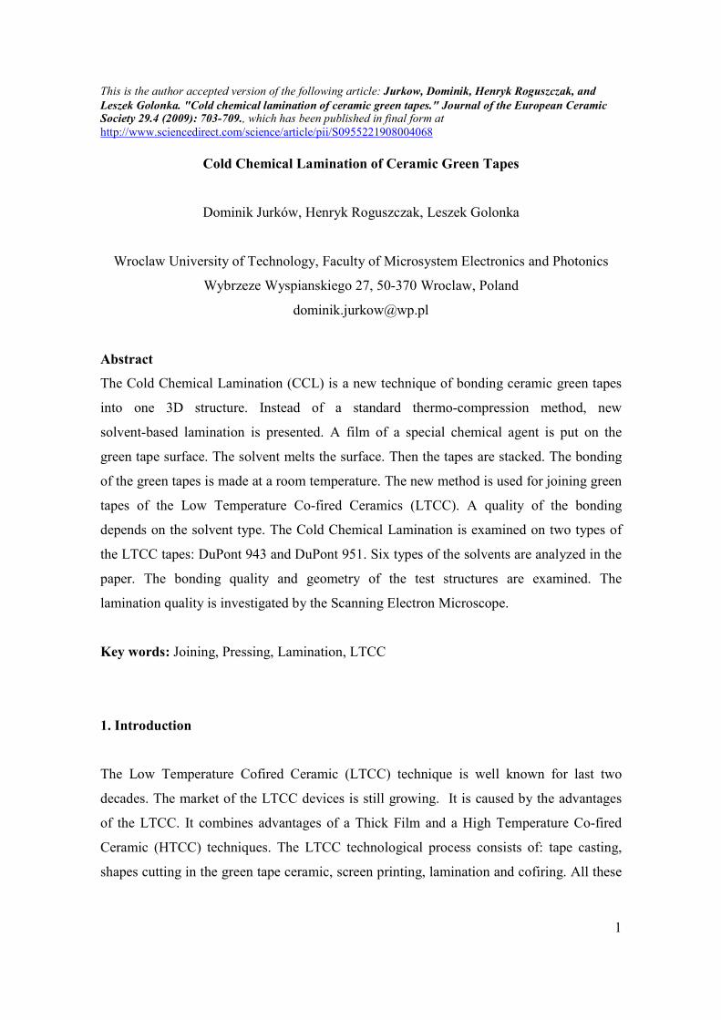
The bonding quality and a chamber geometry can be observed in Fig. 1. The LTCC
structure is laminated by the standard thermo-compression method. The chamber is co-fired
as the close chamber. The cavity dimensions are 10 mm long, 10 mm wide and 165 µm
high (before firing process). The bonding is good. The delaminations are not visible.
However, the chamber deformation can be observed. The cross section of the chamber
middle part is presented in Fig. 1 (b). The cross-section of the chamber left part is shown in
Fig 1 (a) and (c). The presented chambers are deformed significantly. It is caused by too
high pressure. The fugitive phase is needed to create better geometry of the chamber.
This is the author accepted version of the following article: Jurkow, Dominik, Henryk Roguszczak, and
Leszek Golonka. "Cold chemical lamination of ceramic green tapes." Journal of the European Ceramic Society 29.4 (2009): 703-709., which has been published in final form at
http://www.sciencedirect.com/science/article/pii/S0955221908004068
5
a) b)
c)
Fig. 1. SEM micrograph of a cross-section of the co-fired LTCC structure (DuPont 951A2) laminated by the
thermo-compression method. The chamber is a square with the side long 10 mm, high of the cavity is equal to
165 µm before firing, (a), (c) cross section of the chamber left part, (b) cross section of the chamber middle
part.
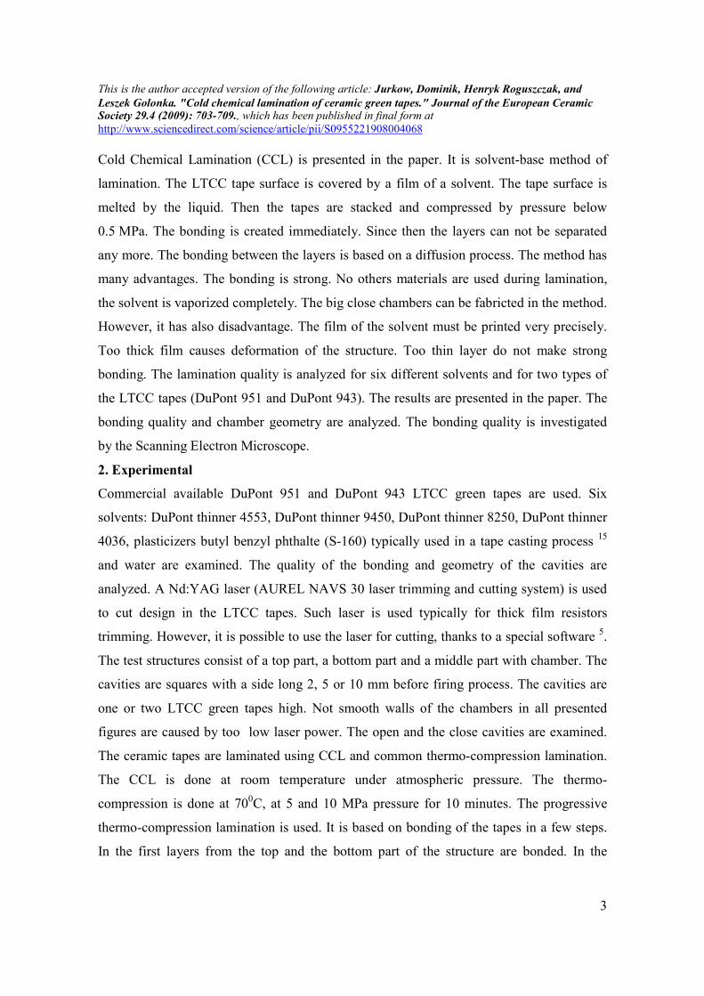
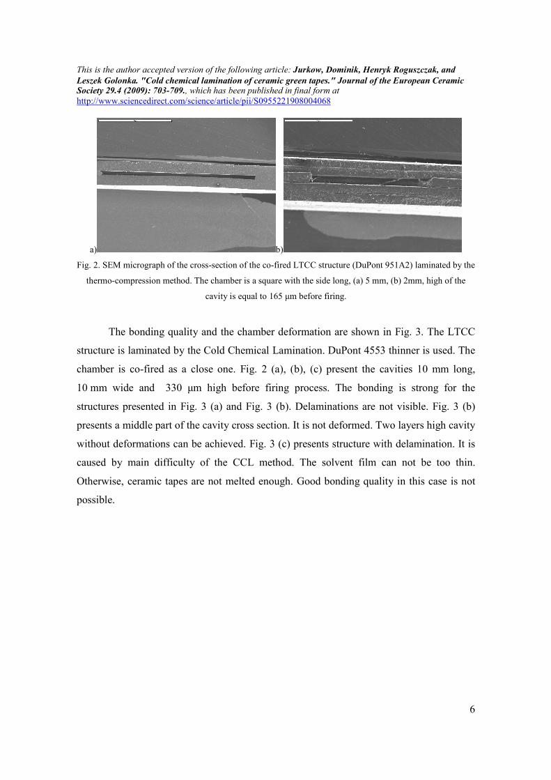
The bonding quality and the chamber deformation are shown in Fig. 2. The LTCC
structure is laminated by the standard thermo-compression method. The chamber is co-fired
as close one. The cavity dimension in Fig. 2 (a) is 5 mm long, 5 mm wide and 165 µm high
and in Fig. 2 (b) is 2 mm long, 2 mm wide and 165 µm high before firing process. The
bonding in Fig. 2 (a) is strong. Delaminations are not visible. However, the chamber in
Fig. 2 (a) is deformed. The top and the bottom part of the structure are laminated in the
middle of the chamber cross section. In Fig. 2 (b) chamber is not deformed any more.
However, the bonding quality is very weak. The borders of the LTCC tapes can be
recognized easily. The higher pressure must be used to ensure good bonding quality.
This is the author accepted version of the following article: Jurkow, Dominik, Henryk Roguszczak, and
Leszek Golonka. "Cold chemical lamination of ceramic green tapes." Journal of the European Ceramic Society 29.4 (2009): 703-709., which has been published in final form at
http://www.sciencedirect.com/science/article/pii/S0955221908004068
6
a) b)
Fig. 2. SEM micrograph of the cross-section of the co-fired LTCC structure (DuPont 951A2) laminated by the
thermo-compression method. The chamber is a square with the side long, (a) 5 mm, (b) 2mm, high of the
cavity is equal to 165 µm before firing.
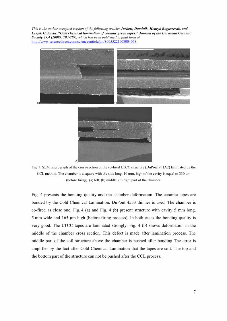
The bonding quality and the chamber deformation are shown in Fig. 3. The LTCC
structure is laminated by the Cold Chemical Lamination. DuPont 4553 thinner is used. The
chamber is co-fired as a close one. Fig. 2 (a), (b), (c) present the cavities 10 mm long,
10 mm wide and 330 µm high before firing process. The bonding is strong for the
structures presented in Fig. 3 (a) and Fig. 3 (b). Delaminations are not visible. Fig. 3 (b)
presents a middle part of the cavity cross section. It is not deformed. Two layers high cavity
without deformations can be achieved. Fig. 3 (c) presents structure with delamination. It is
caused by main difficulty of the CCL method. The solvent film can not be too thin.
Otherwise, ceramic tapes are not melted enough. Good bonding quality in this case is not
possible.
This is the author accepted version of the following article: Jurkow, Dominik, Henryk Roguszczak, and
Leszek Golonka. "Cold chemical lamination of ceramic green tapes." Journal of the European Ceramic Society 29.4 (2009): 703-709., which has been published in final form at
http://www.sciencedirect.com/science/article/pii/S0955221908004068
7
a) b)
c)
Fig. 3. SEM micrograph of the cross-section of the co-fired LTCC structure (DuPont 951A2) laminated by the
CCL method. The chamber is a square with the side long, 10 mm, high of the cavity is equal to 330 µm
(before firing), (a) left, (b) middle, (c) right part of the chamber.
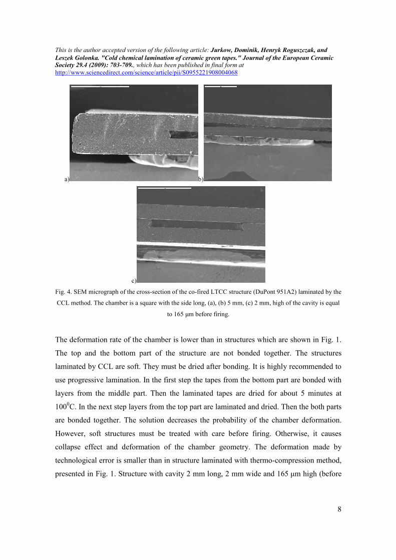
Fig. 4 presents the bonding quality and the chamber deformation. The ceramic tapes are
bonded by the Cold Chemical Lamination. DuPont 4553 thinner is used. The chamber is
co-fired as close one. Fig. 4 (a) and Fig. 4 (b) present structure with cavity 5 mm long,
5 mm wide and 165 µm high (before firing process). In both cases the bonding quality is
very good. The LTCC tapes are laminated strongly. Fig. 4 (b) shows deformation in the
middle of the chamber cross section. This defect is made after lamination process. The
middle part of the soft structure above the chamber is pushed after bonding The error is
amplifier by the fact after Cold Chemical Lamination that the tapes are soft. The top and
the bottom part of the structure can not be pushed after the CCL process.
This is the author accepted version of the following article: Jurkow, Dominik, Henryk Roguszczak, and
Leszek Golonka. "Cold chemical lamination of ceramic green tapes." Journal of the European Ceramic Society 29.4 (2009): 703-709., which has been published in final form at
http://www.sciencedirect.com/science/article/pii/S0955221908004068
8
a) b)
c)
Fig. 4. SEM micrograph of the cross-section of the co-fired LTCC structure (DuPont 951A2) laminated by the
CCL method. The chamber is a square with the side long, (a), (b) 5 mm, (c) 2 mm, high of the cavity is equal
to 165 µm before firing.
The deformation rate of the chamber is lower than in structures which are shown in Fig. 1.
The top and the bottom part of the structure are not bonded together. The structures
laminated by CCL are soft. They must be dried after bonding. It is highly recommended to
use progressive lamination. In the first step the tapes from the bottom part are bonded with
layers from the middle part. Then the laminated tapes are dried for about 5 minutes at
1000C. In the next step layers from the top part are laminated and dried. Then the both parts
are bonded together. The solution decreases the probability of the chamber deformation.
However, soft structures must be treated with care before firing. Otherwise, it causes
collapse effect and deformation of the chamber geometry. The deformation made by
technological error is smaller than in structure laminated with thermo-compression method,
presented in Fig. 1. Structure with cavity 2 mm long, 2 mm wide and 165 µm high (before
This is the author accepted version of the following article: Jurkow, Dominik, Henryk Roguszczak, and
Leszek Golonka. "Cold chemical lamination of ceramic green tapes." Journal of the European Ceramic Society 29.4 (2009): 703-709., which has been published in final form at
http://www.sciencedirect.com/science/article/pii/S0955221908004068
9
firing process) is shown in Fig. 4. (c). The green tapes are joined by CCL method. DuPont
thinner 4553 is used. There is delamination between the top and the middle part of the
structure. It is caused by too thin film of the solvent put on the tapes during the CCL
process. The bonding between other tapes are strong. The cavity is not deformed.
3.2. Lamination of DuPont 943PX tape
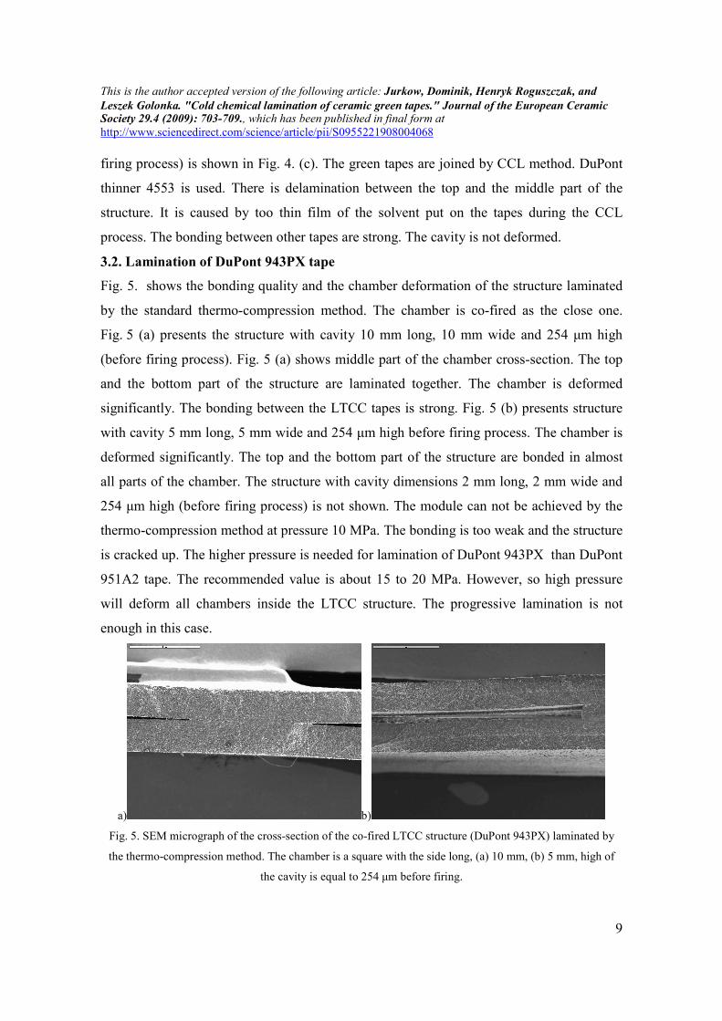
Fig. 5. shows the bonding quality and the chamber deformation of the structure laminated
by the standard thermo-compression method. The chamber is co-fired as the close one.
Fig. 5 (a) presents the structure with cavity 10 mm long, 10 mm wide and 254 µm high
(before firing process). Fig. 5 (a) shows middle part of the chamber cross-section. The top
and the bottom part of the structure are laminated together. The chamber is deformed
significantly. The bonding between the LTCC tapes is strong. Fig. 5 (b) presents structure
with cavity 5 mm long, 5 mm wide and 254 µm high before firing process. The chamber is
deformed significantly. The top and the bottom part of the structure are bonded in almost
all parts of the chamber. The structure with cavity dimensions 2 mm long, 2 mm wide and
254 µm high (before firing process) is not shown. The module can not be achieved by the
thermo-compression method at pressure 10 MPa. The bonding is too weak and the structure
is cracked up. The higher pressure is needed for lamination of DuPont 943PX than DuPont
951A2 tape. The recommended value is about 15 to 20 MPa. However, so high pressure
will deform all chambers inside the LTCC structure. The progressive lamination is not
enough in this case.
a) b)
Fig. 5. SEM micrograph of the cross-section of the co-fired LTCC structure (DuPont 943PX) laminated by
the thermo-compression method. The chamber is a square with the side long, (a) 10 mm, (b) 5 mm, high of
the cavity is equal to 254 µm before firing.
This is the author accepted version of the following article: Jurkow, Dominik, Henryk Roguszczak, and
Leszek Golonka. "Cold chemical lamination of ceramic green tapes." Journal of the European Ceramic Society 29.4 (2009): 703-709., which has been published in final form at
http://www.sciencedirect.com/science/article/pii/S0955221908004068
10
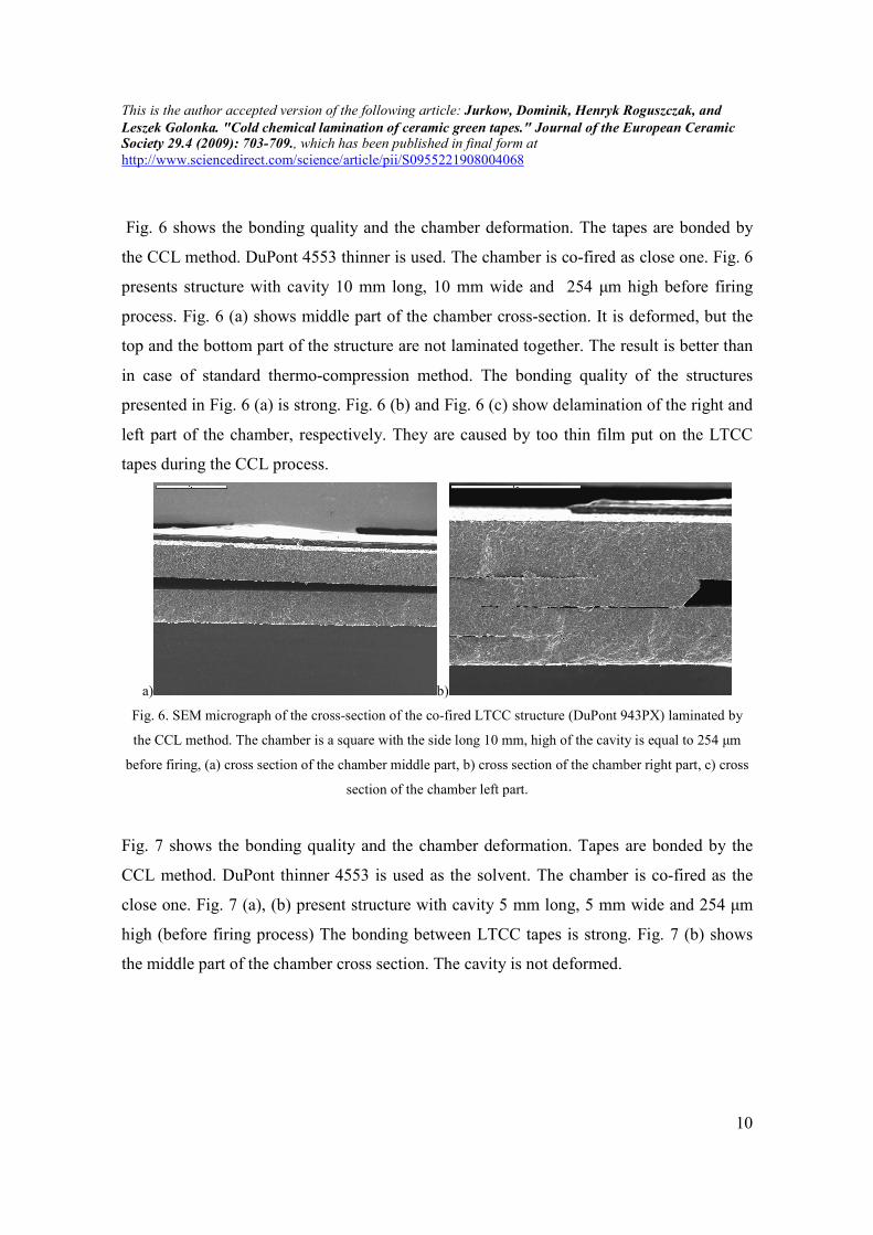
Fig. 6 shows the bonding quality and the chamber deformation. The tapes are bonded by
the CCL method. DuPont 4553 thinner is used. The chamber is co-fired as close one. Fig. 6
presents structure with cavity 10 mm long, 10 mm wide and 254 µm high before firing
process. Fig. 6 (a) shows middle part of the chamber cross-section. It is deformed, but the
top and the bottom part of the structure are not laminated together. The result is better than
in case of standard thermo-compression method. The bonding quality of the structures
presented in Fig. 6 (a) is strong. Fig. 6 (b) and Fig. 6 (c) show delamination of the right and
left part of the chamber, respectively. They are caused by too thin film put on the LTCC
tapes during the CCL process.
a) b)
Fig. 6. SEM micrograph of the cross-section of the co-fired LTCC structure (DuPont 943PX) laminated by
the CCL method. The chamber is a square with the side long 10 mm, high of the cavity is equal to 254 µm
before firing, (a) cross section of the chamber middle part, b) cross section of the chamber right part, c) cross
section of the chamber left part.
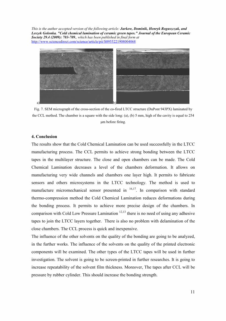
Fig. 7 shows the bonding quality and the chamber deformation. Tapes are bonded by the
CCL method. DuPont thinner 4553 is used as the solvent. The chamber is co-fired as the
close one. Fig. 7 (a), (b) present structure with cavity 5 mm long, 5 mm wide and 254 µm
high (before firing process) The bonding between LTCC tapes is strong. Fig. 7 (b) shows
the middle part of the chamber cross section. The cavity is not deformed.
This is the author accepted version of the following article: Jurkow, Dominik, Henryk Roguszczak, and
Leszek Golonka. "Cold chemical lamination of ceramic green tapes." Journal of the European Ceramic Society 29.4 (2009): 703-709., which has been published in final form at
http://www.sciencedirect.com/science/article/pii/S0955221908004068
11
a) b)
Fig. 7. SEM micrograph of the cross-section of the co-fired LTCC structure (DuPont 943PX) laminated by
the CCL method. The chamber is a square with the side long: (a), (b) 5 mm, high of the cavity is equal to 254
µm before firing.
4. Conclusion
The results show that the Cold Chemical Lamination can be used successfully in the LTCC
manufacturing process. The CCL permits to achieve strong bonding between the LTCC
tapes in the multilayer structure. The close and open chambers can be made. The Cold
Chemical Lamination decreases a level of the chambers deformation. It allows on
manufacturing very wide channels and chambers one layer high. It permits to fabricate
sensors and others microsystems in the LTCC technology. The method is used to
manufacture micromechanical sensor presented in 16,17. In comparison with standard
thermo-compression method the Cold Chemical Lamination reduces deformations during
the bonding process. It permits to achieve more precise design of the chambers. In
comparison with Cold Low Pressure Lamination 12,13
there is no need of using any adhesive
tapes to join the LTCC layers together. There is also no problem with delamination of the
close chambers. The CCL process is quick and inexpensive.
The influence of the other solvents on the quality of the bonding are going to be analyzed,
in the further works. The influence of the solvents on the quality of the printed electronic
components will be examined. The other types of the LTCC tapes will be used in further
investigation. The solvent is going to be screen-printed in further researches. It is going to
increase repeatability of the solvent film thickness. Moreover, The tapes after CCL will be
pressure by rubber cylinder. This should increase the bonding strength.
This is the author accepted version of the following article: Jurkow, Dominik, Henryk Roguszczak, and
Leszek Golonka. "Cold chemical lamination of ceramic green tapes." Journal of the European Ceramic Society 29.4 (2009): 703-709., which has been published in final form at
http://www.sciencedirect.com/science/article/pii/S0955221908004068
12
Acknowledgements
The authors wish to thank the Polish Ministry of Science and Higher Education (grant no.
R02 017 02) for financial support.
Reference
1. Gongora-Rubio, M., Solá-Laguna, L.M., Moffett, P.J., Santiago-Avilés, J.J., The
utilisation of Low Temperature Co-fired Ceramic (LTCC-ML) technology for meso-scale
EMS, a simple thermistor based flow sensor. Sensors and Actuators A, 1999, 73, 215-221.
2. Golonka, L.J., Technology and applications of Low Temperature Cofired Ceramic
(LTCC) based sensors and microsystems. Bulletin of the Polish Academy of Sciences
Technical Sciences, 2006, 54, 221-231.
3. Jurków, D., Golonka, L. J., Roguszczak, H., LTCC gas flow detector. Proceedings of the
European Microelectronics and Packaging Conference & Exhibition, Oulu, Finland, 2007,
204-207.
4. Thelemann, T., Thust, H., Hintz, M., Using LTCC for Microsystems. Microelectronics
International, 2002, 19, 19-23.
5. Kita, J., Dziedzic, A., Golonka, L.J., Zawada, T., Laser treatment of LTCC for 3D
structures and elements. Microelectronics International, 2002, 19, 14-18.
6. Golonka, L.J., Zawada, T., Radojewski, J., Roguszczak, H., Stefanow, M., LTCC
microfluidic system. International Journal of Applied Ceramic Technology, 2006, 3,
150-156.
7. Bembnowicz, P., Golonka, L. J., Ceramic microreactor with integrated heater and
temperature sensor. In Proceedings of the XXXIst International Conference of IMAPS
Poland Chapter (Rzeszow-Krasiczyn), 2007, 429-432.
8. Baker, A., Lanagan, M., Randall, C., Semouchkin, E., Semouchikina, G., Rajab, K.Z.,
Eitel, R., Mittra, R., Rhee, S., Geggier, P., Duschl, C., Fuhr, G., Integration concepts for the
fabrication of LTCC structures. International Journal of Applied Ceramic Technology,
2005, 2, 514-520.
9. Espinoza-Vallejos, P., Zhong, J., Gongora-Rubio, M., Sola-Laguna, L., Santiago-Aviles,
J.J., The measurement and control of sagging in meso (intermediate scale)
This is the author accepted version of the following article: Jurkow, Dominik, Henryk Roguszczak, and
Leszek Golonka. "Cold chemical lamination of ceramic green tapes." Journal of the European Ceramic Society 29.4 (2009): 703-709., which has been published in final form at
http://www.sciencedirect.com/science/article/pii/S0955221908004068
13
electromechanical LTCC structures and systems. In Proceedings of the MRS Conference,
1998, 73-79.
10. Gongora-Rubio, M.R., Espinoza-Vallejos, P., Sola-Laguna, L., Santiago-Avilés, J.J.,
Overview of low temperature co-fired ceramics tape technology for meso-system
technology (MsST). Sensors and Actuators A: Physical, 2001, 89, 222-241.
11. Piwonski, M. A., Roosen, A., Low pressure lamination of ceramic green tapes by
gluing at room temperature. Journal of the European Ceramic Society, 1999, 19, 263-270.
12. Roosen, A., Schindler, K., Cold low pressure lamination of ceramic green tapes. In
Proceedings of the First International Conference and Exhibition on Ceramic Interconnect
and Ceramic Microsystems Technologies, Baltimore, 2005.
13. Roosen, A., New lamination technique to join ceramic green tapes for the
manufacturing of multilayer devices. Journal of the European Ceramic Society, 2001, 21,
1993-1996.
14. Rocha, Z. M., Ibañez Garcia N., Oliveira, N. A., Matos, J., Rosário, D., Gongora-
Rubio, M.R., Low temperature and pressure lamination of LTCC tapes for meso-systems.
In Proceedings of IMAPS Conference and exhibition on Ceramic Interconnect Technology,
Denver, 2004.
15. Majewska, K., Golonka, L. J., Honkamo, J., Jantunen, H., Mielcarek, W., ZnO LTCC
varistors. In Proceedings of the XXVIIth
International Conference of IMAPS Poland
Chapter, Podlesie-Gliwice (Poland), 2003, 158-161.
16. Jurków, D., Golonka, L. J., Roguszczak, H., LTCC gas flow sensor. In Proceedings of
the XXXIth
International Conference of IMAPS Poland Chapter, Rzeszow-Krasiczyn
(Poland), 2007, 279-282.
17. Jurków, D., Golonka, L. J., Roguszczak, H., LTCC gas flow sensor. Elektronika, 2007,
12, 63-64.