cognitive radio systems in lte networks - open access...
TRANSCRIPT
BRUNEL UNIVERSITY, LONDON
Cognitive Radio Systems in LTE Networks
A thesis submitted in partial fulfilment of the requirements for the
degree of Doctor of Philosophy to:
Electronic and Computer Engineering
School of Engineering and Design
Brunel University, UK
By
Anwer Adel Al-Dulaimi
June 2012
i
Abstract
The most important fact in the mobile industry at the moment is that demand
for wireless services will continue to expand in the coming years. Therefore, it is
vital to find more spectrums through cognitive radios for the growing numbers of
services and users. However, the spectrum reallocations, enhanced receivers,
shared use, or secondary markets-will not likely, by themselves or in
combination, meet the real exponential increases in demand for wireless
resources. Network operators will also need to re-examine network architecture,
and consider integrating the fibre and wireless networks to address this issue.
This thesis involves driving fibre deeper into cognitive networks, deploying
microcells connected through fibre infrastructure to the backbone LTE networks,
and developing the algorithms for diverting calls between the wireless and fibre
systems, introducing new coexistence models, and mobility management. This
research addresses the network deployment scenarios to a microcell-aided
cognitive network, specifically slicing the spectrum spatially and providing
reliable coverage at either tier. The goal of this research is to propose new
method of decentralized-to-distributed management techniques that overcomes
the spectrum unavailability barrier overhead in ongoing and future deployments
of multi-tiered cognitive network architectures. Such adjustments will propose
new opportunities in cognitive radio-to-fibre systematic investment strategies.
Specific contributions include:
1) Identifying the radio access technologies and radio over fibre solution for
cognitive network infrastructure to increase the uplink capacity analysis
in two-tier networks.
2) Coexistence of macro and microcells are studied to propose a roadmap
for optimising the deployment of cognitive microcells inside LTE
macrocells in the case of considering radio over fibre access systems.
3) New method for roaming mobiles moving between microcells and
macrocell coverage areas is proposed for managing spectrum handover,
operator database, authentication and accounting by introducing the
channel assigning agent entity. The ultimate goal is to reduce
unnecessary channel adaptations.

ii
Acknowledgements
Foremost, I would like to express my sincere gratitude to my advisor
Professor John Cosmas for the continuous support of my PhD research, for his
motivation, enthusiasm, and immense knowledge. His guidance helped me in all
the time of research and writing of this thesis. I could not have imagined having a
better advisor and mentor for my PhD study.
I would like to express particular gratitude to my wife Saba and the rest of my
family for the encouragement and unending support.
Last but not the least, I am thankful for the great experience I had as a PhD
student, which allowed me to meet many people from different countries across
the globe. This has expanded my visions and ambitions for my future research
and carrier.
iii
Author’s Declaration
I hereby declare that the research recorded in this thesis and the thesis itself
was composed and originated entirely by myself in the Wireless Networks and
Communications Centre (WNCC) at Brunel University. I also certify that all the
information sources and literature used are indicated in the thesis.
Copyright © by
Anwer Adel Al-Dulaimi
2012, London, UK
iv
Table of Contents
Abstract ………………………………...……….………………….………………….
Acknowledgements ………………………………..……………….………………….
Author’s Declaration…………………………………………………………………
Table of Contents …………………………………………………….……………….
List of Figures …………………………..………..………………………..………….
List of Tables ………………………………..……….…………………….…………..
List of Abbreviations…………………………….………………………………..…..
List of Publications…………………………………………………………………….
Chapter 1: Introduction...................................................................................
1.1 Motivation …………………....................................................................................
1.2 Challenges……………………….……………………………………………..…..
1.3 Scenarios and Assumptions…………………………………………….………….
1.4 Aims of Research …………………….....................................................................
1.5 Cognitive Radio over Fibre Solution……………………………………………..
1.6 Contributions to the Knowledge……………………………………….…………..
1.7 References………………………………………………………………………….
Chapter 2: Challenges Facing Cognitive Networks
Deployment………………………………..........…………………….……………
2.1 Cognitive Radio Technique……………..................................................................
2.2 Cognitive Network Functions….…..……………………………………………....
2.2.1 Spectrum Mobility……………………………………………………………
2.2.2 Spectrum Sensing……………………………………………………………..
2.2.2.1 Cooperative Sensing……………………………………….…………..
2.2.2.2 Cyclostationary Detection of Undefined Secondary Users………..…..
2.2.3 Flexibility and Agility…………………………………………….…………
2.2.4 Learning and Adaptability………………………………………….………..
2.2.4.1 Scenario: Neural Network approaches for CR……………….………..
2.2.4.2 Solution: Multilayer Feedforward Neural Networks Framework...…..
2.2.5 Dynamic Spectrum Access.……………………………………….………..
2.3 Network Planning………………………………………………………………..…
2.4 Distributed Network Architecture…………………………………………………
i
ii
iii
iv
viii
xi
xii
xv
1
1
2
4
5
6
8
11
14
15
17
17
19
19
20
20
21
22
23
25
26
28
v
2.4.1 Network Management Scenario………………………………………………
2.4.2 The Heterogeneous Network Scenario...……………………………………..
2.4.3 System Model……..………………………………………………………….
2.5 Centralised Network Management……………………………………………
2.5.1 Joint Spectrum Allocation ……………………………………………………
2.5.2 System Model………………………..……………………………………….
2.6 Hybrid Network Management……………………………………………………
2.6.1 Overview…………………………………..………………………………
2.6.2 System Model………………………………………..……………………….
2.6.3 Multi–hop Problem……………………………...……………………………
2.7 Cooperative and non-Cooperative Spectrum Sharing……..……………………….
2.8 Conclusion………………………………………………………………………….
2.9 References………………………………………………………………………….
Chapter 3: Cognitive Radio over Fibre and Uplink Capacity
for Microcellular Applications………………...……………………………
3.1 Introduction……………….………………………………………….…………….
3.2 Motivation………………………………………………………………………….
3.3 Related Work………………………………………………………………………
3.4 Technical contributions…………………………………………………………...
3.5 System Model………………………………………………………………………
3.5.1 Dynamic Spectrum Access for Cognitive Network ………………………..
3.5.2 Problem Solution for Spectrum Sharing ……………………………………..
3.6 CRoF Framework…………………………………………………………………..
3.7 System Models…………………………………….……………………………….
3.7.1 Call Diversion Algorithm……………..………………………………………
3.7.2 Spectral Efficiency of CRoF Microcellular Model……………………...……
3.7.2.1 Model Formulation ……………………………………….…………..
3.7.2.2 Model Evaluations ………………………………………………...…..
3.8 Radio Access Technologies………………………………………………………..
3.8.1 CRoF as Independent System….……………………………………………..
3.8.1.1 CRoF_AP………………………………………………….…………..
3.8.1.2 CRoF_bridge…….………………………………………………...…..
3.8.2 CRoF as Dependent System……..……………..……………………………..
3.8.2.1 CRoF_PR_AP…………………………………………….…………..
3.8.2.2 CRoF_PR_bridge…….…………………………………………...…..
28
30
31
32
32
33
34
34
36
37
39
40
41
45
45
46
47
48
49
49
51
52
55
55
61
61
63
65
66
66
68
69
69
70
vi
3.9 Network Modelling………………………………………………………………
3.9.1 LTE Macrocell……….……………………………………………………….
3.9.2 IEEE802.11e for Microcell Cognitive Users……...…………………………
3.10 Event Scheduling…………………………………………...…………………….
3.11 Simulations...…………………………………………………………………….
3.12 Conclusion………………………………………………………………………..
3.13 Reference………………………………………………………………………….
Chapter 4: Optimising Cell Size and Power Consumption for
LTE Networks……………....…………………………………………………....
4.1 Motivation………………………………………………………………………….
4.2 Technical Contributions…………………..………………………………………..
4.3 Dimensioning of Cognitive Networks………………….………………………….
4.4 Coexistence Modelling……………….…………………………………………..
4.4.1 Space Filling…………..……………………………………………………
4.4.2 Time Filling…………….……………………………………………………..
4.5 Coexistence Scheduling for LTE and WLAN…………….……………………..
4.5.1 LTE Model Design…….……………………………………………………
4.5.1.1 Channel-dependent Scheduling………………………….…………..
4.5.1.2 Uplink Control Channel Format for LTE Scheduler...…….…………..
4.5.2 WLAN Model Design in OPNET…………………………………………..
4.6 Optimising Cognitive Network Architecture………………………………………
4.6.1 System Setup……………………………………………………………….…
4.6.2 Simulation Results…….……………………………………………………..
4.7 Power Consumption Planning………..……………………………………………
4.7.1 Case Study……………...……………………………………………………..
4.7.2 Area Spectral Efficiency……………………………………………………
4.7.3 Area Power Consumption...…………………………………………………
4.7.4 Deployment Scenarios……..…………………………………………………
4.7.5 Results………………….…..…………………………………………………
4.8 Conclusion………………………...………………………………………………..
4.9 Reference………………………..………………………………………………….
71
71
72
74
76
81
82
85
86
88
88
91
91
96
99
100
100
102
103
107
107
109
113
113
114
115
116
118
120
121
vii
Chapter 5: Mobility Management in Cognitive Networks………..
5.1 Introduction………………………………………………………………………..
5.2 Challenges of Dynamic Resources Allocation……..………………………………
5.2.1 Channel Access Management………….……………………………………..
5.2.1.1 Location Management…………….……………………….…………..
5.2.1.2 Handover Management…………...……………………….…………..
5.2.2 Handover in Cognitive Networks………………………..………….………..
5.2.3 Spectrum Forecasting…………...………………………..………….………..
5.3 IP Modelling………………..………………………………………………………
5.3.1 Introducing the CAA………………………………………………….………
5.3.2 Model Formulation………………………………………………………….
5.3.3 The New Handover Scheme……………….…………………………………
5.4 Spectrum Handover Mechanism……………………………………………….…..
5.4.1 Channel Availability Algorithm...…………………………………….………
5.4.2 Channel Adaptation Algorithm……………………………………………….
5.5 Mobility Performance Evaluation………….………………………………………
5.5.1 Simulation Scenario………….....…………………………………….………
5.5.2 Results………………………..……………………………………………….
5.6 Fairness of the Channel Assigning Scheme…..………………………………….
5.6.1 Background……...……………………………………………………………
5.6.2 Performance Evaluation…………………………………………………….
5.6.2.1 Network Settings………………….……………………….…………..
5.6.2.2 Results…………………..………...……………………….…………..
5.7 Multi-Zoned Spectrum Sharing.…………………………………………………..
5.8 Cell Migration between Zones of Service…….………………………………….
5.8.1 Case 1: Cell moving between zones.……………………………….………
5.8.2 Case 2: Independent cell between zones…………………………….………
5.8.3 Case 3: Cell trapped by one zone………..………………………….………
5.9 Conclusion………….………………………………………………………………
5.10 References……..………………………………………………………………….
Chapter 6: Conclusions and Future Work……………………………..
6.1 Conclusions………………………………………………………………………...
6.2 Future Work………………………………………………………………………..
125
126
128
129
129
130
132
133
135
136
137
140
142
142
144
146
146
148
152
152
153
153
154
157
159
160
162
163
164
164
168
168
170
viii
List of Figures
Figure 2.1: Spectrum allocations between different wireless domains…..…..…… 16
Figure 2.2: Spectrum mobility and handover process………...…..………………. 18
Figure 2.3: Architecture of a spectrum agile radio………………...….…………... 21
Figure 2.4: Designed MFNN learning model for dependent CR……...………….. 24
Figure 2.5: CR adaptations between various transmission opportunities.………… 26
Figure 2.6: Distributed spectrum management solution….....…………………….. 29
Figure 2.7: The underlying architecture in cognitive network employing
distributed microcells…….……...…………………………………….
30
Figure 2.8 Centralised spectrum management solution...………………………... 33
Figure 2.9: Hybrid spectrum management solutions……………………………... 35
Figure 2.10: Routing scenarios in cognitive network ………...……………………. 38
Figure 3.1: Allocating users in dynamic spectrum access model…………….…… 50
Figure 3.2: CRoF system frameworks………………………………………….…. 53
Figure 3.3: Call diversion scheme………………………………………………… 57
Figure 3.4: The general CRoF marco/micro two-tier model…………...…..……... 62
Figure 3.5: The Spectrum savings vs. ratio for microcells/macrocells…………… 64
Figure 3.6 CRoF system using APs………………………………………………. 67
Figure 3.7: CRoF system using bridges……….………………………………….. 68
Figure 3.8: CRoF to primary using APs……………...…………………………… 69
Figure 3.9: CRoF to primary using bridges……………….………………………. 70
Figure 3.10: Relationships of key IFS times……………………...………………... 73
Figure 3.11: Call diversion algorithm 3.1 installation inside the LTE macrocell BS 74
Figure 3.12: The process model for call_div node unit…………………………….. 75
Figure 3.13 The MGMT process model for the macrocellular lte_as node unit…... 75
Figure 3.14: End-to-end time delay vs. free time available for cognitive
communications………………………………..……………………...
78
Figure 3.15: Medium Access Delay vs. free time available for cognitive
communications………………………………………...……………..
79
Figure 3.16: Retransmission Attempts vs. free time available for cognitive
communications…………..……………………………………….…..
79
Figure 3.17: Cognitive throughput vs. free time available for cognitive
communications……………………………………………………....
80
Figure 4.1: CRoF core and microcells coexistence with the primary users. At
different locations, the microcells identify the free local opportunities
ix
for transmissions and use them …………….………………………… 91
Figure 4.2: Adding more microcells to fixed sized LTE macrocell. The
microcells can be side to side or overlapped in their coverage
areas………………..………………………………………………….
94
Figure 4.3: The adaptation of microcell coverage area when microcell diameter is
2r……………………………………………………………………….
95
Figure 4.4: The adaptation of microcell coverage area when microcell diameter is r……………………………..………………………………………….
95
Figure 4.5: Subscriber coverage analysis…………………………………………. 95
Figure 4.6: Time filling where each new microcell is assigned to one of the IEEE
802.11 5 GHz frequency band………………….……………………..
98
Figure 4.7: LTE channel-dependent scheduling in time and frequency
domains…………………………………………………..…………....
101
Figure 4.8: New 802.11e MAC layer model to update the control plane with new
installed BSs…………………………………………………………...
103
Figure 4.9: CRoF throughput vs. number of microcells………….……………….. 110
Figure 4.10: CRoF end-to-end time delay vs. number of microcells………………. 110
Figure 4.11: CRoF Medium Access Delay vs. number of microcells……………... 111
Figure 4.12: CRoF total packets dropped vs. number of microcells...……………... 112
Figure 4.13: Cells resources allocated in fully loaded non-divided system..………. 114
Figure 4.14: Hexagonal macrocell network………………………………………... 116
Figure 4.15: Different scenarios of micro with LTE macrocell at the
centre…………………………………………………………………..
117
Figure 4.16: Area power consumption vs. inter site distance for different
micro/macro deployments…………………....………………….…..
119
Figure 4.17: Area power consumption vs. throughput for different micro/macro
deployments……………………………………………….…..…….
119
Figure 5.1: Location management schemes….…………………………………… 129
Figure 5.2: Handover management operations……………………………………. 131
Figure 5.3: The CAA entity as part of IP protocol………………………………... 137
Figure 5.4: Operation of intercell spectrum handover……………………………. 138
Figure 5.5:
Figure 5.6:
Figure 5.7:
Inter/Intra cell spectrum handover……..……...………………………
Scheme for spectrum handover using same channel ( )…….………...
Scheme for spectrum handover while changing to ( )...……………..
139
140
141
Figure 5.8: Spectrum handovers events for a cognitive mobile station move
between different microcellular and macrocellular domains………….
146
Figure 5.9: End-to end time delays as a function for the mobile speed………….. 148
x
Figure 5.10: Throughput as a function for the mobile speed...…………………….. 149
Figure 5.11: AP connectivity vs. mobile locations as shown in Figure
5.9………………………………………………………………..,……
150
Figure 5.12: Traffic sent as a function for the mobile speed……...………………... 151
Figure 5.13: Traffic received as a function for the mobile speed…………………... 151
Figure 5.14: Connection performance study model………………………………... 153
Figure 5.15: Connections aborted with/without CAA...……………………………. 155
Figure 5.16: Connections rejected with/without CAA……………………………... 155
Figure 5.17: Connections aborted vs. guaranteed calls with CAA as a function for
traffic applied loading…………………………………………………
156
Figure 5.18: Multi-access cellular network of CRoF and CR base stations……….. 158
Figure 5.19: Cell migrations between two zones……………………..……………. 161
Figure 5.20: Independent cell coexistences with zones…………………………….. 162
Figure 5.21: Independent cell trapped by one zone………………………………... 163
xi
List of Tables
Table 3.1: Transition States for Cognitive Network Spectrum Access ....…… 51
Table 3.2: Assumption values for BW savings Evaluations……………...…. 64
Table 3.3: Network Settings for the simulation………….……………...…. 77
Table 4.1: CRoF System Technologies………………..……………...……. 90
Table 4.2: Network Settings for Capacity Evaluations…………………..…. 108
Table 4.3: Simulation Parameters for Power Calculations………………….. 118
Table 5.1: Simulated Mobile Station Speeds……………………………….. 147
Table 5.2: Network Settings for Simulating CAA…..……………………... 154
xii
List of Abbreviations
21CN 21st Century Network
AC Access Category
AIFS Arbitration Inter-Frame Space
AIFSN AIFS Number
AP Access Point
AR Access Router
ASE Area Spectral Efficiency
B3G Beyond the third Generation
BER Bite Error Rate
BS Base Stations
BT British Telecom
BW Bandwidth
CAA Channel Assigning Agent
CAK Channel-Adaptation-acKnowledgement
CAP Channel-Adaptation
CAR Channel-Adaptation-Request
CBS Central Base Station
CDMA Code Division Multiple Access
CMN Cognitive Mesh Network
CMT Cell Migration Time
CN Correspondent Node
CRAHN Cognitive Radio Ad-Hoc Network
CRN Cognitive Radio Network
CRoF Cognitive Radio over Fibre
CSCC Common Spectrum Control Channel
CSMA/CA Carrier Sense Multiple Access/Collision Avoidance
CW Contention Window
DCF Distributed Coordination Function
DHCP Dynamic Host Configuration Protocol
DIFS DCF Inter-Frame Space
DL Downlink
xiii
DL-SCH Downlink- shared channel
DSA Dynamic Spectrum Access
DSE Dependent Station Enablement
EDCA Enhanced Distributed Coordinated Access
ETSI European Telecommunications Standards Institute
FCC Federal Communications Commission
FFT Fast Fourier Transform
FMIPv6 Fast Handover in MIPv6
FTTH Fibre-To-The Home
GSM Global System for Mobile Communications
HA Home Agent
HCS Hierarchical Cell Structures
IETF Internet Engineering Task Force
IFS Inter-Frame Space
IP Internet Protocol
ISD Inter-Site Distance
ISM Industrial, Scientific and Medical
IUT International Telecommunication Union
LSC List of the Candidate Channels
LTE Long Term Evolution
LTE-A Long Term Evolution-Advanced
MAC Medium Access Layer
MANET Mobile Ad–Hoc Network
MCS Modulation Coding Scheme
MFNN Multilayer Feedforward Neural Networks
MIMO Multiple-Input Multiple-Output
MIPv6 Mobile IPv6
MME Mobility Management Entity
MTU Maximum Transmission Unit
NNs Neural Networks
NO Network Operator
NUC Number of Candidate Channels
OFCOM Office of Communications
xiv
OFDM Orthogonal Frequency-Division Multiplexing
PHY Physical
PR Primary
PRB Physical Resource Blocks
QoS Quality-of-Service
RAT Radio Access Technology
RBS Remote Base Station
RF Radio Frequency
RoF Radio over Fibre
RRM Radio Resource Management
SB Spectrum Broker
SCFDMA Single-carrier Frequency-Division Multiple Access
SDR Software-Defined Radio
SH Spectrum Handover
SLS Spectrum Load Smoothing
SM Service Manager
SNR Signal-to-Noise-Ratio
SON Self-Organisation Network
SP Spectrum Server
SPPP Spatial Poisson Point Process
TBs Transport Blocks
TCP Transmission Control Protocol
TTI Transmission Time Interval
UDP User Datagram ProtocolF
UE User Equipment
UL Uplink
UL-SCH Uplink- shared channel
USUC Urgent Secondary Users Coexistence
VoIP Voice over Internet Protocol
WG Working Groups
WLAN Wireless Local Area Network
WLANoF Wireless LAN over Fibre
WRAN Wireless Regional Area Networks
xv
List of Publications
Book:
1. A. Al-Dulaimi, J. Cosmas, and A. Mohammed, Organization and Green
Applications in Cognitive Radio Networks, Pennsylvania, USA: IGI
Global, Jan. 2013 (In production).
Book Chapters:
2. A. Al-Dulaimi, S. Al-Rubaye, and J. Cosmas, “Adaptive Coexistence
between Cognitive and Fibre Networks,” in Wireless Multi-Access
Environments and Quality of Service Provisioning: Solutions and
Application. G. M. Muntean and R. Trestian, Ed. Pennsylvania, USA:
IGI Global, 2011, pp. 311 - 336.
3. S. Al-Rubaye, A. Al-Dulaimi, and J. Cosmas, “Spectrum Handover
Strategies for Cognitive Femtocell Networks”, in Femtocell
Communications: Business Opportunities and Deployment Challenges.
R. A. Saeed, B. S. Chaudhari, and R. A. Mokhtar, Ed. Pennsylvania,
USA: IGI Global, 2011, pp. 85 - 102.
Journals:
4. A. Al-Dulaimi and J. Cosmas “Optimum Planning for Cognitive Radio
over Fibre Networks and Microcells Installation”, IEEE/ACM
Transactions on Networking, 2012 (Under review).
5. A. Al-Dulaimi and J. Cosmas, “Mobility Management in Cognitive
Networks”, IEEE Transactions on Vehicular Technology, 2012 (Under
review).
6. A. Al-Dulaimi and J. Cosmas, “Spectral Efficiency of CRoF
Microcellular Model,” IEEE Electronic Letters, 2012 (Under review).
7. A. Al-Dulaimi and J. Cosmas, “Challenges facing Cognitive Networks
Deployment,” IEEE Communications Surveys & Tutorials, 2012 (Under
review).
8. A. Al-Dulaimi, H. Al-Raweshidy, J. Cosmas, and J. Loo, “Cognitive
Mesh Networks, Cognitive Radio over Fibre for Microcells
xvi
Application”, IEEE Vehicular Technology Magazine, vol. 5, no. 3,
2010, pp. 54 - 60.
9. S. Al-Rubaye, A. Al-Dulaimi and J. Cosmas, “Cognitive Femtocell,
Future Wireless Networks for Indoor Applications”, IEEE Vehicular
Technology Magazine, vol. 6, no. 1, 2011, pp. 44 - 51.
10. S. Al-Rubaye, A. Al-Dulaimi, H. Al-Raweshidy, “Next Generation
Optical Access Network using CWDM Technology”, International
Journal of Communications, Network and System Sciences (IJCNS), no.
7, 2009, pp. 636 - 640.
White papers:
11. A. Al-Dulaimi et al, “Cognitive Radio Systems,” white paper, eMobility
Technology Platform, Expert Working Group (EWG7), Nov. 11, 2009.
12. A. Al-Dulaimi et al, “SARA, Strategic Applications Agenda and
Strategic Research Agenda, Future Internet,” white paper, eMobility CA
consortium, 2010.
Conferences:
13. A. Al-Dulaimi, S. Al-Rubaye and J. Cosmas, “Adaptive Congestion
Control for Mobility in Cognitive Radio Networks,” In proceedings of
the 7th
International Conference on Wireless Advanced(WiAd), Kings
College London, London, 2011, pp. 273 - 277.
14. S. Al-Rubaye, A. Al-Dulaimi, and J. Cosmas, “Pilot Power
Optimization for Autonomous Femtocell Networks,” ,” In proceedings
of the 7th
International Conference on Wireless Advanced(WiAd), Kings
College London, London, 2011, pp. 170 - 175.
15. A. Al-Dulaimi, S. Al-Rubaye, J. Cosmas, I. Siaud, and P. Cordier,
“Radio over Fibre,” Orange Briefing, WWRF#25 meeting, London, Nov
2010.
16. A. Al-Dulaimi, S. Al-Rubaye and H. Al-Raweshidy, “Radio over Fibre
Transceiver Designed for Cognitive Communications Architecture,”
WWRF#25 meeting, London, Nov 2010.
xvii
17. A. Al-Dulaimi and J. Cosmas, “Mobility Management for Microcells
based Cognitive Radio over Fibre Networks,” WWRF#25 meeting,
London, Nov 2010.
18. A. Al-Dulaimi, S. Al-Rubaye, H. Al-Raweshidy, J. Cosmas, and J. Loo,
“Multi-Zones of Cognitive to Fibre Networks,” In proceedings of the 7th
IEEE International Symposium on Communication Systems, Networks
And Digital Signal Processing (CSNDSP’10), Newcastle, UK, 2010, pp.
697 - 700.
19. A. Al-Dulaimi and L. AL-Saeed, “An Intelligent Scheme for First Run
Cognitive Radios,” In proceedings of the 4th
IEEE International
Conference and Exhibition on Next Generation Mobile Applications,
Services, and Technologies (NGMAST'10), Amman, 2010, pp. 158 -
161.
20. A. Al-Dulaimi, S. Al-Rubaye, and H. Al-Raweshidy, “Renovate
Cognitive Networks under Spectrum Unavailability,” In proceedings of
the 6th
Advanced International Conference on Telecommunications
(AICT 2010), Barcelona, Spain, 2010, pp. 41 - 45.
21. A. Al-Dulaimi and H. Al-Raweshidy, “Cognitive Radio over Fibre for
Microcells Applications,” Wireless World Research Forum (WWRF-
WG6), Penang Island, Malaysia, 2010.
22. S. Al-Rubaye, A. Al-Dulaimi, L. Al-Saeed, H. Al-Raweshidy, E.
Kadhum, W. Ismail ,“Development of Heterogeneous Cognitive Radio
and Wireless Access Network,” WWRF#24, Malaysia, April 12 - 14,
2010.
23. A. Al-Dulaimi, “CRoF: Cognitive Radio over Fibre,” 2010 European
Reconfigurable Radio Technologies Workshop, Mainz, Germany,
2010, pp.181 - 182.
24. A. Al-Dulaimi, N. Radhi, and H. S. Al-Raweshidy, “Cyclostationary
Detection of Undefined Secondary Users,” In proceedings of the 3rd
International Conference and Exhibition on Next Generation Mobile
Applications, Services, and Technologies (NGMAST'09), Cardiff, UK,
2009, pp. 230 - 233.
25. A. Al-Dulaimi and H. S. Al-Raweshidy, “Multi-Operator Cognitive
Radios Sharing One Channel,” In proceedings of the 7th
ACM
xviii
international symposium on Mobility management and wireless access
(MobiWac’09), Tenerife, Spain, 2009, pp. 114 - 117.
Tutorials:
26. A. Al-Dulaimi, “Cognitive Radio over Fibre for Future Mesh
Networks,” Industry Forum (IF) of the IEEE International Conference
on Communications (ICC2012), Ottawa, Canada, 2012.
27. A. Al-Dulaimi and Saba Al-Rubaye, “Cognitive Radios in LTE
Networks,” Industry Forum (IF) of the IEEE Global Communications
Conference (GLOBECOM), California, USA, 2012, (Accepted).
Chapter One: Introduction
1
Chapter 1
Introduction
1.1 Motivation
The Cognitive Radio over Fibre (CRoF) is proposed as a new technology
solution to overcome the problem of spectrum unavailability through multi-
access radio terminals with landline connections. The CRoF architecture is based
on using the Radio over Fibre (RoF) to connect cognitive base stations. In this
way, the new CRoF stations can choose to transmit to each other via fibre
whenever they fail to formulate wireless links. One application of the CRoF
system is the cognitive microcells. These CRoF microcells are positioned inside
the primary macrocell coverage areas and in coexistence with the primary Base
Stations (BSs). Accordingly, CRoF system would be able to utilise local
spectrum holes efficiently, trade resources easily with primary networks, achieve
reliable and short communications, and provide higher throughput to the
secondary users [1 - 3].
Network Operator (NO) of the wireless Beyond the third Generation (B3G) era
will need to be directing terminals to the most appropriate radio networks of its
heterogeneous infrastructure. This requires advanced terminal management
functionality for conducting optimal network selections, in a seamless to the user
manner [4]. Although very few studies for an infrastructure enhanced secondary
usage of spectrum can be found in the literature, some recent work has the
potential to be adopted for such use. A good example is Code Division Multiplex
Access CDMA-based Hierarchical Cell Structures (HCS) in which macrocell and
Chapter One: Introduction
2
microcell layers are sharing the same frequency band [5].
The links of Cognitive Radio Networks (CRNs) are generally opportunistic,
asymmetric, or unidirectional, which creates challenges to feedback real-time
and perfect information from the destination to the source (e.g., ACK). The
opportunistic and unidirectional link is a special nature of CRN. Considering a
link between CR node and CR node in CRN, node having an opportunity
to transmit to node in certain time duration does not warrant an opportunity for
node to transmit back to node [6] or even giving any feedback such as
acknowledging packets. Obviously, only heterogeneous networks consisting of
optical and wireless networks can respond to the requirements of the evolution of
such a diverse mobile coexistence in future networks. Although, Cognitive radio
over fibre techniques is not the first system that combines microcells services
through fibre, its novelty is coming from exploiting the local spectrum holes of
the allocated spectrum [7 - 9].
The all-important requirements of portability can be improved by the use of
microcells. A microcell is a region served by a radio base unit, just as in current
cellular systems, only smaller in area by one-to-two orders of magnitude [10].
There were different architectures presented for the radio-over fibre linking to
the microcellular system. In one model, an optical source at the BS is shared
between all microcells. Also, the coverage of each microcell is much smaller
than that of the present macrocell so that the power consumption and size of the
handset could be reduced significantly [11]. These logistics of application are
incorporated with cognitive systems in order to achieve new models for cognitive
network deployment with lower impacts on the current networks in operation.
1.2 Challenges
The rising demand in wireless communication for free available spectrum goes
along with the challenges of managing the network access to spectrum
utilisation, i.e., Quality-of-Service (QoS) requirements, as for instance in
delivering services at high interruption loss. Efforts such as the EU-FP7
FARAMIR, CREW, and COST-TERRA projects [12 - 14] indicate the level of
activity in the field which has the potential to develop an architecture that can be
extended to include hybrid networks that are able to support both cellular type of
Chapter One: Introduction
3
operations and ad-hoc type of operations. The system architecture considers
coordination between the different networks and elements that share the available
spectrum. These approaches allow cognitive radios to support and guarantee QoS
when sharing channels without requiring direct information exchange in
observing past spectrum utilisation. The motivation comes from the major
regulators in the USA and UK, Federal Communications Commission (FCC) and
the Office of Communications (OFCOM), who have released many evaluations
for the spectrum usage by TV broadcasters. These reports show a considerable
“White Spaces” in the spectrum without any usage of the related frequency band
by broadcasters. Particularly, in the area around and between major cities where
the usage of the related bands by secondary spectrum access approaches can be
envisaged [15, 16]. One key concern is to evaluate the expected amount of
spectrum available to secondary users in dynamically changing wireless
environments. The answer varies significantly according to the scenarios of
application and the approach of establishing connections between the anticipated
end-users and the access network.
The driven force behind this concern is that operators have limited flexibility
when it comes to capacity step-upgrades to meet future demand. Inventors have
pushed the efficiency of mobile technologies near to theoretical limits. Some
gains are still possible, with the cognitive radio depending on the starting point,
but much more than this is very difficult (or expensive). Spectrum is also limited
and only becomes available infrequently when auctions are held. Even the most
optimistic plans for spectrum release would only double the holdings for cellular
networks so at best another factor of two gains. So relying on small-cell solutions
will emerge as there are no other options for meeting capacity requirements.
At the heart of these challenges, lies the ability to exploit the best future for a
country's wireless communications infrastructure and efficient resource
management. In the UK, there is no organisation in charge with doing this - the
regulator OFCOM is the closest the industry that has a national custodian for
policy change. This is exactly the issue tackled in this work where the new
models of cognitive radio networks are studied and evaluated with a particular
attention to emerging radio access technologies and systematic performance.
Chapter One: Introduction
4
1.3 Scenarios and Assumptions
The spectrum availability is a decisive factor for the continuity of CRN
continuity of transmission. Cognitive networks lease the spectrum temporarily
whenever the primary users are inactive. Thus, localised wireless changes within
CRN cells rapidly affect the transmissions of the cognitive radios. This situation
becomes more complicated for cognitive mesh networks when establishing a
multi-hop link. Therefore, link formation failure may cause complete disruption
at certain sites of the network. A mathematical model is first introduced to study
the delay impacts of the spectrum unavailability in the cognitive mesh network
which has been analysed as the most severe cause for the transmission failures.
The use of cognitive over fibre microcells to support cognitive mesh networks
is a brand new idea. Therefore, none of the literature quantitatively addresses the
impact of using alternative landline connections in the secondary networks such
as the changes in the network architecture, cognitive practical capacity, balancing
services and the quality of the data coverage. This thesis starts by achieving of
robust local resources sharing using a developed Medium Access Layer (MAC)
layer for efficient spectrum utilisation and less heterogeneous complexity that
lead to the development of new algorithms of users’ coexistence and Internet
Protocol (IP) mobility managements. This reduces the collision in services due to
primary users’ activities by addressing the following questions:
i. What are the necessary modifications to the cognitive mesh network to
achieve multi–tiered cognitive network with CRoF installation?
ii. What is the optimal number of CRoF microcells that can be installed
inside LTE macrocell?
iii. How to arrange the spectrum coexistence of the new installed CRoF
microcells with primary users transmitting in the existing band-channels?
To answer these questions, various CRoF radio access technologies are
investigated for possible deployment in microcells. This provides a clear vision
for network planning in the initial steps for cognitive network emergence. Then,
new techniques for understanding the limits of cognitive users’ numbers that can
be served are identified under certain spectrum availability assumptions. In this
Chapter One: Introduction
5
regard, two approaches namely: Space Filling and Time Filling are proposed for
sharing resources. Firstly, in space filled, cognitive microcells would be able to
control and adapt their coverage areas from inter-lapping with each other.
Practically, a cognitive macrocell is located amongst other microcells with
different levels of awareness and independence, where any channel can be used
by different non-adjacent microcells using the frequency reuse principles.
Secondly, the microcells are installed randomly throughout the macrocell where
their coverage areas can overlap and spectrum is used by all microcells as one
common pool. In this regards, spectrum load smoothing is used to analyse the
capacity of different Wireless Local Area Network (WLAN) and Long Term
Evolution (LTE) base stations as an approach for exploring the number of
stations that can coexist in a certain cell size.
The CRoF technology that installs microcells connected via fibre to the main
macrocell station raises many questions about the validity of the CRoF solution
because of the dynamic adaptation between channels named as Spectrum
Handover (SH) for cognitive mobile users moving at different speeds. The
handover here is not just a registration with a new operator station, but it is also a
negotiation to get access to the available channels locally in coexistence with the
primary users. Therefore, it is necessary to develop a new scheme for roaming
new mobiles moving between microcells and macrocell coverage areas to reduce
unnecessary channel adaptations. This is necessary to validate the applicability of
the proposed CRoF technology for the next-generation network applications.
1.4 Aims of Research
Since the research presented in this thesis tackles multiple issues, the aims are
multi-fold:
1. Considering a macrocellular scenario where users communicate in an
orthogonal manner enabling local access to the spectral ranges at shorter
links without interfering actual license owners. For the first time, our
analysis attempts to quantify the achievable gain for various CRoF Radio
Access Technologies (RATs) with respect to classical radio devices. In
order to do so, a call diversion algorithm is introduced for diverting calls
Chapter One: Introduction
6
between different microcellular and macroculler domains through
landline network.
2. The coexistence of LTE macro and WLAN microcells is addressed to
propose a policy for optimising the deployment of cognitive microcells
inside macrocells in the case of considering radio over fibre access
systems. The goal is to set limits for equipment density installation as a
function of the free spectrum transmission opportunities, which is
believed to be potential success factor for future cognitive radio network
deployment and offer insights into how to design CRoF architecture. To
LTE, a new algorithm for scheduling durations is proposed to improve
spectrum access. To WLAN, a new transmission adaption scheme is
proposed to discover new surrounding installed microcells and adapting
the transmission domain features.
3. Where the cognitive radio behaviour is generalised to allow secondary
users to transmit simultaneously with the primary system. Specifically,
CRoF microcells are combined with multi-user diversity technology to
achieve strategic spectrum sharing and self-organising communications
through managing the mobility at various end-users speeds. In this field,
the Channel Assigning Agent (CAA) is introduced in this thesis to
allocate the same channel used by a cognitive mobile user as long as
possible. This will prevents service interruption resulted from
unnecessary spectrum handovers. The problem of congestion
management due to the CAA installation is addressed to analyse the
impacts of allocating channels on user selection strategy. More
development for the channel allocation using multi-zoned network
domains is proposed for future analysation and research.
1.5 Cognitive Radio over Fibre Solution
Restoring cognitive network services cannot be performed using the traditional
procedures for link re-formulation in mobile communications. This is due to the
dynamic nature of the spectrum holes’ availability, auction schemes on
resources, and the reconfiguration methods to access resources. Therefore, a
permanent solution is necessary to guarantee the transmission of the future
Chapter One: Introduction
7
cognitive mesh network. Thus, the most realistic solution is to combine the
CMNs with the landline networks. This expands the broadcast options for the
cognitive network in order to attain reliable delivery services. The fibre network
is proposed as the promising landline technology for this new hybrid cognitive-
to-landline arrangement. As a matter of fact, fibre networks are re-gaining high
interest for their multiple product advantages, such as high bandwidth, low
power consumption, and low cost. Furthermore, many undergoing projects are
currently investigating the advantages for delivering many services via fibre
networks. For example, the British Telecom (BT) 21st Century Network (21CN)
programme [17], and the Japanese national institute of information and
communications technology Fibre-To-The Home (FTTH) projects [18].
The integrated connection between the fibre network and the cognitive base
stations can be easily made and in a cost effective way. This combination is
named Cognitive Radio over Fibre (CRoF). This CRoF system is using the radio
over fibre as the alternative land line connection between the new CRoF base
stations in case of not being able to formulate a wireless link. Radio over fibre
technology gives a lot of advantages, such as moving the complicated signal
processing to the Central Base Station (CBS) location, therefore the overall
system is cost effective and the Remote Base Station (RBS) is very simple,
passive and compact (therefore it is transparent and its maintenance is easy).
Such system is very cost–effective because of localisation of signal processing in
CBS and also because the Base Station is simple. The reliability of the system is
high due to the simple and passive structure of the RBS. This system can easily
serve densely populated areas, such as shopping malls and airports, dead-zone
areas and highways can be covered efficiently and economically. The system can
also support multiple wireless standards. Because of the high bandwidth nature
of optical fibre, Broadband services are more feasible using this technology [19].
For all the above mentioned reasons, the integration of optical and wireless
systems is considered to be one of the most promising solutions for increasing
the existing capacity and mobility as well as decreasing the costs in next-
generation optical access networks [20]. Radio-over-Fibre is a suitable
technology to provide a cost-effective solution for delivering high data rates, as
well as for extending the range of the existing wireless access networks. The
remotely located BSs are interconnected via a Central Office (CO) is using a
Chapter One: Introduction
8
low-loss optical fibre network [21]. Frequency independent low fibre loss, high
bandwidth, and increasing availability of low-cost optoelectronic and RF
integrated components are the major drivers for fibre optics RF solution [22].
Several key enabling technologies for hybrid optical-wireless access networks
are raised by [20], including optical millimetre-wave (mm-wave) generation, up-
conversion, transmission in a downlink direction, and full-duplex operation
based on wavelength reuse by using a centralised light source in an uplink
direction.
The CRoF system concepts need to develop a new radio that is equipped with
fibre connections. The anticipated CRoF radio is an extended version for
Mitola’s cognitive radio. Such an extension includes extra physical portals for
accessing landlines and transferring signals on-time from wireless to wired
modulation forms. This operation occurs whenever the CRoF radio failed to
formulate a wireless link. This process should not take long time intervals during
conversions in order to keep real time broadcasting between terminal handsets.
This development can be done only by very powerful software programmable
transceiver units that can adapt on demand promptly. The other major adjustment
in the CRoF radio is to extend the intelligence of the cognition machine. This
allows the CRoF radio to make on-time decisions and choose the efficient link
between wireless and fibre connections. The extended cognition engine also
helps to explore the surrounding wireless environment to select between the
available short and long wireless links and fibre connections. All these
transmission assessment challenges must be performed by this extended
cognition engine. Actually, these modifications may impact the computational
complexity of the suggested CRoF radio and increase the time of processing for
various communication attempts. However, a small comparison between the pros
and cons of the CRoF radio shows that the outcomes of the new radio system are
much higher than setback factors as shown in later chapters. The most interesting
thing about the CRoF is the high reliability in delivering the data, which is the
main problem that cognitive radio is suffering from.
1.6 Contributions to the Knowledge
In this thesis, a roadmap is defined for installing the future cognitive radio
Chapter One: Introduction
9
network for efficient access to the spectrum and posing several constraints in the
management and strategies for creating novel architecture using multiple access
system. Within this setting, different system models are considered in which
cognitive users compete for a chance to transmit simultaneously with the primary
system. On the basis of these models, a specific resource allocation problem is
defined to order insight how to design local access systems in a cognitive radio
network environment. We initially integrate the cognitive wireless systems to the
radio over fibre network to create a new access system namely as Cognitive
Radio over Fibre (CRoF) to allow flexible selection for the transmission media
and narrowing transmission wireless domains throughout the mesh network.
Within this setting, a base station transmits over a certain time or frequency band
only when no other user does and can choose to communicate through fibre with
other stations to avoid major transmissions interruptions if the primary user
returns to use its licensed band. Next, the CRoF concept is extended to include
cognitive microcellular domains that transmit simultaneously in coexistence with
the primary user over the same frequency band. This is performed as long as the
level of interference with the primary user remains within an acceptable range
and to slice the macrocellular area as a function for the spectrum availability.
New schemes are investigated for allocating channels at different CRoF - RATs
systems and user selection in a network consisting of multiple secondary
transmitters and receivers communicating all together in the presence of the
primary system. The emphasis is on the capability of the proposed approach to
allow cognitive devices to support and guarantee QoS for the future Internet
applications, while sharing spectrum. The main concern is to design a secondary
heterogeneous network that does not interfere with existing licensed services.
In Chapter 2, the known architectures for cognitive networks are presented
with the essential characteristics for dynamic spectrum interruption loss. The
different performance metrics of different models are studied to develop the
proposed system models and the assumptions used throughout most of this thesis.
The coordination of spectrum sharing is considered in which the primary and the
cognitive user wish to communicate, subject to allocation schemes and entities.
The setback of the current proposals for cognitive network modelling is served
by focusing on maintaining connections and service delivery. A mathematical
model is proposed to analyse the additional time delays incurred by frequency
Chapter One: Introduction
10
adaptation between various cognitive mesh network base stations. The
conclusions are used to investigate solutions and algorithms in later chapters.
In Chapter 3, a macro-to-macrocellular system is considered where users
communicate in an orthogonal manner enabling local access to the spectral
ranges at shorter links without interfering actual license owners. For the first
time, our analysis attempts to examine the overall throughput gained from
various CRoF-RATs with respect to classical radio devices. A new diversion call
algorithm is proposed for this microcellular/macrocellular integrated network.
This involves three different modules that are installed at the cell core server,
macrocell, and microcell units. The ultimate goal here is create a heterogeneous
model system of primary and secondary networks in coexistence and to obtain a
characterisation of higher performance connections within such a scenario.
In Chapter 4, the coexistence of macro and microcells stations is considered in
order to propose a policy for optimising the deployment of cognitive microcells
inside macrocells. The goal is to set limits for users’ density installation as a
function of the free spectrum channels which is believed to be potential factor for
future cognitive radio network deployment and offer insights into how to design
CRoF architecture. The study is combined with the algorithms developed in
chapter three and the given solutions for cognitive microcellular systems.
Simulation results show the limits of newly hosted microcells in LTE cells that
can maintain the best performance. At the end, models are presented for the
deployment of micro sites that allow to significantly decreasing the area power
consumption in the network while still achieving certain area throughput targets
and efficient services delivery.
Results in Chapter 4 showed that cognitive microcells can be extended to allow
the SU to transmit simultaneously with the PU over the same channels band. This
is exactly the setup in Chapter 5, where the cognitive radio behaviour is
generalised to allow secondary users to transmit simultaneously with the primary
system. Specifically, it is proposed in this chapter to combine CRoF microcells
with multi-user diversity technology to achieve strategic spectrum sharing and
self-organising communications through managing the mobility at various end-
users speeds. In this field, CAA is proposed to allocate the same channel to a
cognitive mobile user as long as possible to prevent service interruption resulted
from unnecessary spectrum handovers. The problem of fairness management due
Chapter One: Introduction
11
to the CAA installation on user selection strategy is addressed to assess the
success of the proposed solution for targeted aim. Finally, the big sized cognitive
network is divided into many zones of services at which CRoF-BS acts as the
core of the zones. Therefore, a new paradigm for local resources sharing emerges
through these architectural network modifications.
1.7 References
[1] A. Al-Dulaimi, H.S. Al-Raweshidy, J. Cosmas, and J. Loo, “Cognitive
Mesh Networks, Cognitive Radio over Fibre for Microcells Application,”
IEEE Vehicular Technology Magazine, vol. 5, no. 3, 2010, pp. 54 - 60.
[2] A. Al-Dulaimi, S. Al-Rubaye, H.S. Al-Raweshidy, J. Cosmas, and J. Loo,
“Multi-Zones of Cognitive to Fibre Networks,” In proceedings of the
IEEE, IET International Symposium on Communication Systems, Networks
And Digital Signal Processing (CSNDSP’10), Newcastle, UK, 2010, pp.
762 - 765.
[3] A. Al-Dulaimi, S. Al-Rubaye, and H.S. Al-Raweshidy, “Renovate
Cognitive Networks under Spectrum Unavailability,” In proceedings of the
Sixth Advanced International Conference on Telecommunications (AICT
2010), Spain, 2010, pp. 41 - 45.
[4] P. Demestichas, “Enhanced network selections in a cognitive wireless B3G
world”, Springer, Annals of Telecommunication, vol. 64, no. 7 - 8, 2009,
pp. 483 - 501.
[5] A. Attar, S. A. Ghorashi, M. Sooriyabandara, and A.H. Aghvami,
“Challenges of Real-Time Secondary Usage of Spectrum,” Computer
Networks: The International Journal of Computer and Telecommunications
Networking, vol. 52, no. 4, 2008, pp. 816 - 830.
[6] C. K. Yu, K. C. Chen and S. M. Cheng, “Cognitive Radio Network
Tomography,” IEEE Transactions on Vehicular Technology, vol. 59, no. 4,
2010, pp. 1980 - 1997.
[7] C. Y. Lee, H. G. Kang, and T. Park, “A Dynamic Sectorization of
Microcells for Balanced Traffic in CDMA: Genetic Algorithms Approach,”
IEEE Transactions on Vehicular Technology, vol. 51, no. 1, 2002, pp. 63 -
72.
Chapter One: Introduction
12
[8] M. Sauer, A. Kobyakov, and J. George, “Radio Over Fiber for Picocellular
Network Architectures,” Journal of Lightwave Technology, vol. 25, no. 11,
2007, pp. 3301 - 3320.
[9] H. Li, A. Attar, V. C. M. Leung, and Q. Pang, “Collision Avoidance and
Mitigation in Cognitive Wireless Local Area Network over Fibre,” In
proceedings of the 1st International Conference on Evolving Internet
(INTERNET’09), Canada, 2009, pp. 133 - 138.
[10] L. J. Greenstein, N. Amitay, T. -S. Chu, L.J. Cimini Jr., G. J. Foschini, M.
J. Gans, I. Chih-Lin, A. J. Rustako, R. A. Valenzuela, and G. Vannucc,
“Microcells in Personal Communications Systems,” IEEE Communication
Magazine, vol. 30, no. 12, 1992, pp. 76 - 88.
[11] J. S. Wu, J. Wu, and H. W. Tsao, “A Radio-over-Fiber Network for
Microcellular System Application,” IEEE Transactions on Vehicular
Technology, vol. 47, no. 1, 1998, pp. 84 - 94.
[12] FP7-ICT FARAMIR Project. Internet: http://www.ict-faramir.eu/,
Accessed: July 20, 2012.
[13] FP7-CREW Project. Internet: http://www.crew-project.eu/, Accessed: July
20, 2012.
[14] COST Action IC0905 TERRA. Internet: http://www.cost-terra.org/,
Accessed: July 20, 2012.
[15] Federal Communications Commission, In the Matter of Unlicensed
Operation in the TV Broadcast Bands. ET Docket, no. 04 - 186, September
23, 2010.
[16] OFCOM, Cognitive Radio Technology: A Study for Ofcom - Volume 1,
QINETIQ/06/00420, no. 1.1, 12th
February 2007.
[17] POSTnote, Next Generation Telecoms Networks. Parliamentary office of
science and technology, No. 296 Next Generation Networks, 2007.
[18] T. Hamanaka, X. Wang, N. Wada, and K. I. Kitayama, “Compound Data
Rate and Data-Rate-Flexible 622 Mb/s-10 Gb/s OCDMA Experiments
Using 511 - Chip SSFBG and Cascaded SHG-DFG-Based PPLN
Waveguide Optical Thresholder,” IEEE Journal of Selected Topics in
Quantum Electronics, no. 13, no. 5, 2007, pp. 1516 - 1521.
[19] R. Abdolee, R. Ngah, V. Vakilian, and T. Rahman, “Application of Radio-
Over-Fiber (ROF) in Mobile Communication,” In proceedings of the Asia-
Chapter One: Introduction
13
Pacific Conference on Applied Electromagnetics (APACE), Melaka,
Malaysia, 2007.
[20] Z. Jia, J. Yu, G. Ellinas, and G. K. Chang, “Key Enabling Technologies for
Optical-Wireless Networks: Optical Millimeter - Wave Generation,
Wavelength Reuse, and Architecture,” Journal of Lightwave Technology,
no. 25, no. 11, 2007, pp. 3452 - 3471.
[21] F. Lucarz and A. Seeds, “Gigabit/s Wireless over Fibre Systems for Future
Access Networks,” 2009, Accessed: Sept 29, 2010, from
www.ee.ucl.ac.uk/lcs/previous/LCS2005/44.pdf
[22] H. S. Al-Raweshidy and K. Komaki, Radio over Fibre Technologies for
Mobile Communication Networks, Boston/London, Artech House
Publisher, 2002.
Chapter Two: Challenges Facing Cognitive Networks Deployment
14
Chapter 2
Challenges Facing Cognitive
Networks Deployment
In this chapter, the known cognitive network models are presented with the
main challenges that are facing the deployment of these network managements.
The cooperative and non-cooperative architectures are considered in which the
primary and the cognitive user wish to communicate with no interference.
Additionally, the study focuses on the spectrum sharing challenge in distributed
and centralised spectrum access cases. Due to users fully sharing the same
spectral resource, spectrum availability is a decisive factor for the continuity of
CRN services. Thus, localised wireless changes within CRN cells rapidly affect
the transmissions of the cognitive radio base stations. This situation becomes
more complicated for cognitive mesh networks when establishing a link over
many transmission domains. Therefore, link formation failure may cause
complete disruption at certain sites of the network. A mathematical model is
introduced to show the delay impacts of the spectrum unavailability on the
CRN’s which has been analysed as the most severe cause for the CRN failures.
System models and problem formulations are proposed in order to study the
impacts of spectrum unavailability on uplink capacity for each of the CRN
application scenarios, for which solutions and algorithms are investigated in this
thesis.
Chapter Two: Challenges Facing Cognitive Networks Deployment
15
2.1 Cognitive Radio Technique
Cognitive radios (CRs) are perceived as a possible solution to the future low
availability of the radio spectrum. It is a key technology that could enable
reliable, flexible, and efficient spectrum access by adapting the mobile operating
features according to the surrounding wireless environment. CRs are facilitated
by the rapid and significant development in radio technologies (e.g., Software-
Defined Radio (SDR), frequency, and power control) and can be characterised by
the utilisation of disruptive techniques such as real time spectrum allocation,
wideband spectrum sensing, and real-time measurement dissemination.
This revolutionary and transforming technology represents a paradigm shift in
the design of wireless systems, as it will allow the agile and efficient utilisation
of the radio spectrum by offering distributed terminals or radio cells the ability of
radio sensing, self-adaptation, and dynamic spectrum sharing. Cooperative
communications and networking is another new communication technology
paradigm that allows distributed terminals in a wireless network to collaborate
through some distributed transmission or signal processing so as to realise a new
form of space diversity to combat the detrimental effects of fading channels.
Spectrum utilisation can be improved significantly by allowing a secondary user
to utilise a licensed band when the Primary user (PR) is absent. Cognitive radio,
equipped with sensing and adapting to the environment, is able to fill in spectrum
holes and serve its users without causing harmful interference to the licensed
user. To do so, the CR must continuously sense the spectrum it is using in order
to detect the reappearance of the PR. Once the PR is detected, the CR should
withdraw from the spectrum so as to minimise the interference it may possibly
cause [1].
Several definitions for cognitive radio can be found from the research domain.
The official definition for cognitive radio systems in ITU- developed by ITU-
RWP1B in 2009 and published in (ITU-R 2009) states that a cognitive radio
system is [2]:
“A radio system employing technology that allows the system to
obtain knowledge of its operational and geographical
environment, established policies and its internal state; to
dynamically and autonomously adjust its operational parameters
and protocols according to its obtained knowledge in order to
Chapter Two: Challenges Facing Cognitive Networks Deployment
16
achieve predefined objectives; and to learn from the results
obtained”.
In other words, once cognitive radios can find the opportunities using the
“spectrum holes” for communications, cognitive radio networking to transport
packets on top of cognitive radio links is a must to successfully facilitate useful
applications and services. A mobile terminal with cognitive radio capabilities can
sense the communication environments (e.g. spectrum holes, geographic
location, available wire/wireless communication system or networks, available
services), analyse and learn information from the environments with user’s
preferences and demands, and reconfigure itself by adjusting system parameters
conforming to certain policies and regulations. For example, when a cognitive
radio mobile terminal sensed that there are WiFi and Global System for Mobile
Communications (GSM) systems nearby while spectrum holes exist in the
frequency band of digital TV, it may decide to download files from a certain
WiFi access point, make a phone call through GSM system and communicate
with other cognitive radio users using those spectrum holes. A cognitive radio
terminal could also negotiate with other spectrum and/or network users to enable
more efficient spectrum and network utilisation. The negotiation procedure may
be facilitated from the support of network/infrastructure or just proceed in an ad–
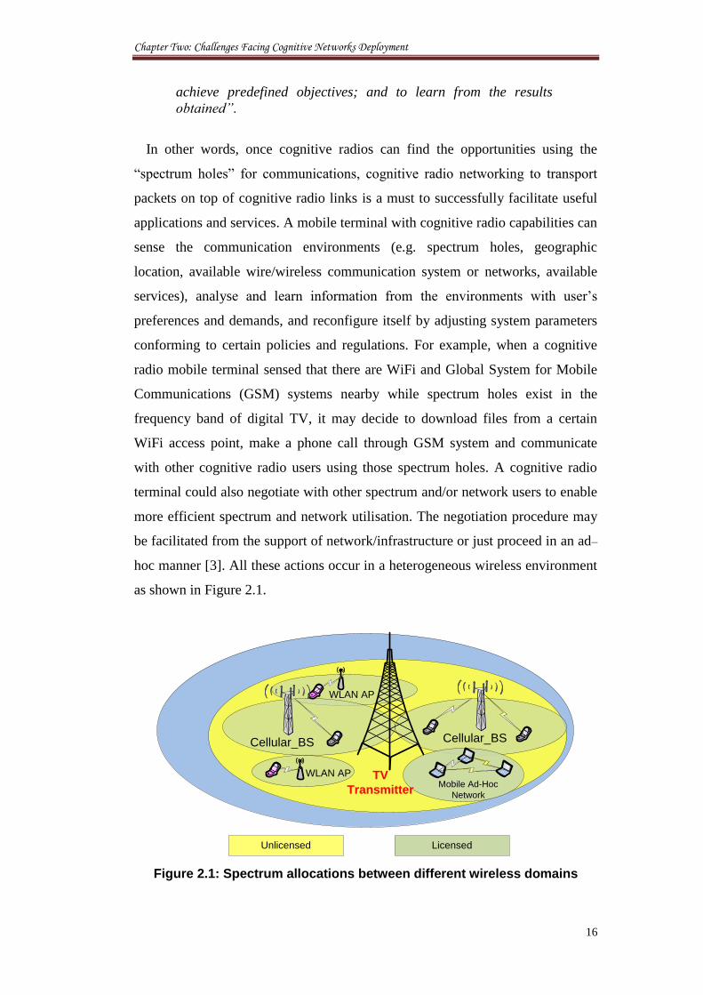
hoc manner [3]. All these actions occur in a heterogeneous wireless environment
as shown in Figure 2.1.
Cellular_BS
TV
Transmitter
WLAN AP
WLAN AP
Cellular_BS
Mobile Ad-Hoc
Network
LicensedUnlicensed
Figure 2.1: Spectrum allocations between different wireless domains
Chapter Two: Challenges Facing Cognitive Networks Deployment
17
This chapter researches on the issues that had driven the focus on using fibre
deeper into wireless networks and the approaches to gain more spectrum. It
addresses the challenges in wireless access and communications for known
cognitive network managements. The following analysis discusses several more
specific cases which can be summarised in the following:
1. The link creation for cognitive networks.
2. Given the current cognitive network architectures, the challenges for
significantly expanding future spectrum requirements to achieve reliable
communications.
3. Understanding the extent of base stations reallocation in order to respond
to the growth in wireless demand locally.
4. Increases in spectrum capacity based upon radio access technologies
using unlicensed spectrum over the long–term, while following short–
term solutions to meet the growth in wireless demand.
While the spectrum access process has undergone substantial modelling, the
allocation and reallocation process has not. These have a geo-location function
and there should be provided with a scheme to enable to check a database of
broadcaster frequencies. The known cognitive network management functions
were summarised and conclusions were applied as a proposed management in
this study for the new CRoF network. The key issues to be addressed include, in
particular, where, when and how a cognitive BS should access the spectrum and
use resources, how to manage call exchange in the cognitive network, and how to
utilise the relevant information to handle the diverse resources efficiently.
2.2 Cognitive Network Functions
2.2.1 Spectrum Mobility
Spectrum mobility refers to the agility of cognitive radio networks to
dynamically switch between different channels. These secondary users have no
guarantees for continuous spectrum access in any of the licensed bands due to the
dynamic changes in the availability of vacant spectrum bands over time.
Therefore, spectrum mobility becomes an important factor when designing
cognitive domains. One of the primary factors affecting spectrum mobility is the
Chapter Two: Challenges Facing Cognitive Networks Deployment
18
delay incurred during spectrum handover. This delay adversely affects protocols
employed at various layers of the communication protocol stack. Another
important factor to be considered in spectrum mobility is the time difference
between the secondary network detecting a primary transmission and the
secondary users leaving spectral band. Transmissions from secondary users
during this period will cause harmful interference to the primary users. The
OFCOM has suggested setting upper bounds on the spectrum handover duration
to avoid prolonged interference to primary users [4].
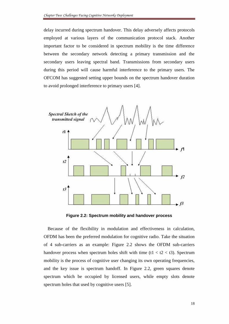
Figure 2.2: Spectrum mobility and handover process
Because of the flexibility in modulation and effectiveness in calculation,
OFDM has been the preferred modulation for cognitive radio. Take the situation
of 4 sub-carriers as an example: Figure 2.2 shows the OFDM sub-carriers
handover process when spectrum holes shift with time (t1 < t2 < t3). Spectrum
mobility is the process of cognitive user changing its own operating frequencies,
and the key issue is spectrum handoff. In Figure 2.2, green squares denote
spectrum which be occupied by licensed users, while empty slots denote
spectrum holes that used by cognitive users [5].
Chapter Two: Challenges Facing Cognitive Networks Deployment
19
2.2.2 Spectrum Sensing
One of the primary requirements of cognitive networks is their ability to scan
the spectral band and identify vacant channels available for opportunistic
transmission. As the primary user network is physically separated from the
secondary user network, the secondary users do not get any direct feedback from
primary users regarding their transmission. The secondary users have to depend
on their own individual or cooperative sensing abilities to detect primary user
transmissions [6].
Traditionally, there are two techniques which are used for spectrum sensing:
energy detection and cyclostationary feature detection. The energy detector
measures energy in each narrowband channel and determines the presence of a
primary user if the energy detected in a narrowband channel is higher than a
certain threshold. However, to achieve high receiver sensitivity, a low threshold
has to be used. In some cases, the threshold has to be lower than the noise floor,
in which case the detection fails. The problem is even more complicated due to
the fact that the noise is most likely non-Gaussian because of the presence of CR
user’s interference. The other spectrum sensing technique is cyclostationary
feature detection. Most of the signals encountered in wireless communications
are cyclostationary, whereas the noise is stationary. As a result, the
cyclostationarity of the primary signals can be used to detect their presence. The
cyclostationarity of a signal is not reflected in the Power Spectral Density (PSD);
however it is reflected in the Spectral Correlation Density (SCD) function which
is obtained by taking the Fourier transform of the cyclic autocorrelation function.
Therefore, spectral correlation analysis of the received data can be used to
identify the signal source and occurrence [7].
2.2.2.1 Cooperative Sensing
In a fading environment, spectrum sensing is challenged by the uncertainty
arising from the channel fading since the secondary user now has to distinguish
between a white space, where there is no primary signal and a deep fade, where it
is hard to detect the primary signal. As such, under channel fading, a single user
relying solely on local (signal) processing may be unable to get an accurate
detection results, required by the regulator, in a reasonable time limit. To tackle
this issue, different secondary users may share their measurements and
Chapter Two: Challenges Facing Cognitive Networks Deployment
20
cooperatively determine whether the primary user is present. The diversity gain
achieved through such cooperation effectively cancels the deleterious effect of
fading. This raises a natural question: how much processing and cooperation is
needed, respectively, in order to achieve a certain performance level? This can be
characterised as a tradeoff between the local processing and the user cooperation
[8].
2.2.2.2 Cyclostationary Detection of Undefined Secondary Users
The possibility that a certain CR may transmit illegally falls outside the current
definitions of cognitive networks. These cognitive radios can use their advanced
radio technologies to adapt their carrier frequencies to transmit on a certain
licensed channel when the primary user is off. However, they still need to
transmit using different signal parameters to keep their broadcast dedicated to
their end users. This action may occur at any time and can happen rarely or even
constantly. A novel monitoring system is required to grant the competency to
detect such behaviour immediately at the basic base stations. The Fast Fourier
Transform (FFT) Accumulation method is presented as the algorithm for
analysing the cyclic spectrum. This method is derived from the cyclostationary
method which is widely accepted as the most effective sensing procedure for the
cognitive radios [9, 10].
2.2.3 Flexibility and Agility
Flexibility and agility is the ability of the CR to change the waveform and
other radio operational parameters on the fly. In contrast, there is a very limited
extent that the current multichannel-multiradio can do this. Full flexibility
becomes possible when CRs are built on top of SDRs. Another important
requirement to achieve flexibility, which is less discussed, is to use
reconfigurable or wideband antenna technology. Thus, a new paradigm of
wireless communications emerges with adaptive physical and medium access
layers. These allow the spectrum agile radio to change its transmission features
in order to react to changes in the external radio environment and the dynamic
spectrum access policies. An internal architecture of an individual agile radio is
depicted in Figure 2.3.
Chapter Two: Challenges Facing Cognitive Networks Deployment
21
Policy Interaction
Opportunity Manager
Flexible PHY LayerOp
po
rtu
nity Id
en
tifie
r
Figure 2.3: Architecture of a spectrum agile radio
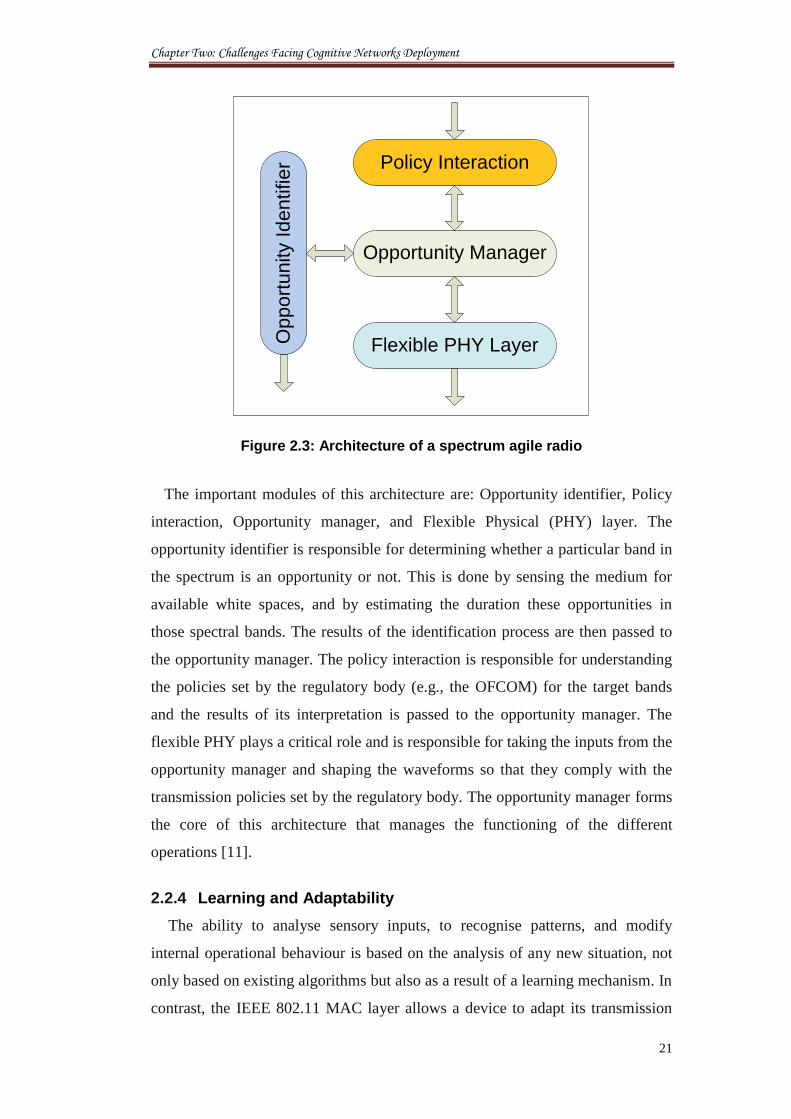
The important modules of this architecture are: Opportunity identifier, Policy
interaction, Opportunity manager, and Flexible Physical (PHY) layer. The
opportunity identifier is responsible for determining whether a particular band in
the spectrum is an opportunity or not. This is done by sensing the medium for
available white spaces, and by estimating the duration these opportunities in
those spectral bands. The results of the identification process are then passed to
the opportunity manager. The policy interaction is responsible for understanding
the policies set by the regulatory body (e.g., the OFCOM) for the target bands
and the results of its interpretation is passed to the opportunity manager. The
flexible PHY plays a critical role and is responsible for taking the inputs from the
opportunity manager and shaping the waveforms so that they comply with the
transmission policies set by the regulatory body. The opportunity manager forms
the core of this architecture that manages the functioning of the different
operations [11].
2.2.4 Learning and Adaptability
The ability to analyse sensory inputs, to recognise patterns, and modify
internal operational behaviour is based on the analysis of any new situation, not
only based on existing algorithms but also as a result of a learning mechanism. In
contrast, the IEEE 802.11 MAC layer allows a device to adapt its transmission
Chapter Two: Challenges Facing Cognitive Networks Deployment
22
activity to sense channel availability. However this is achieved by using a
predefined listen-before-talk and exponential backoff algorithm instead of a
cognitive cycle. These might need to be improved with further techniques and
schemes in order to increase the awareness of the CR systems in the wireless
environment and achieve better control of the radio technical features that
enables high levels of configurability and interoperability. This can be done by
integrating the neural networks with future CR to provide these radios with the
ability to recognise different transition states. This is explained as follows:
2.2.4.1 Scenario: Neural Network approaches for CR
Neural networks have been used in many researches for cognitive radio
applications to improve the intelligence capacities. Zhang [12] proposed four
layer Back-Propagation Neural Network which can be used for different
applications including the CR. Each layer consists of a number of neurons that
receive inputs from other neurons in the previous layer. If the weighted sum of
the inputs exceeds a threshold level then the neuron will produce an output and
distribute it to the neurons in the next layer.
Multilayer Feedforward Neural Networks (MFNN) was used by [13] as an
effective technique for real-time characterisation of the CR system performance.
This is based on measurements carried out by the radio and therefore offers some
interesting learning capabilities. Simulations were used to obtain a set of data
characterising the performance with respect to these measurements. A subset of
this data was used to train a MFNN; afterwards, the rest of the data was set to
compare the performance of the prediction provided by the trained MFNN with
the actually experienced performance.
Potential solution presented by [14] argues to assist the cognitive radios in the
derivation and enforcement of decisions regarding the selection of the desired
radio configuration that optimises its QoS. The proposed solution is based on
Neural Networks (NNs) motivated by the fact that NNs are widely different from
conventional information processing as they have the ability to learn from given
examples, thus being also able to perform better in cognitive tasks. Two NN-
based learning schemes have been set up and tested: the ‘basic’ and the
‘extended’ one. While the former aims at building the framework for developing
such learning schemes and applying them into future cognitive radio based
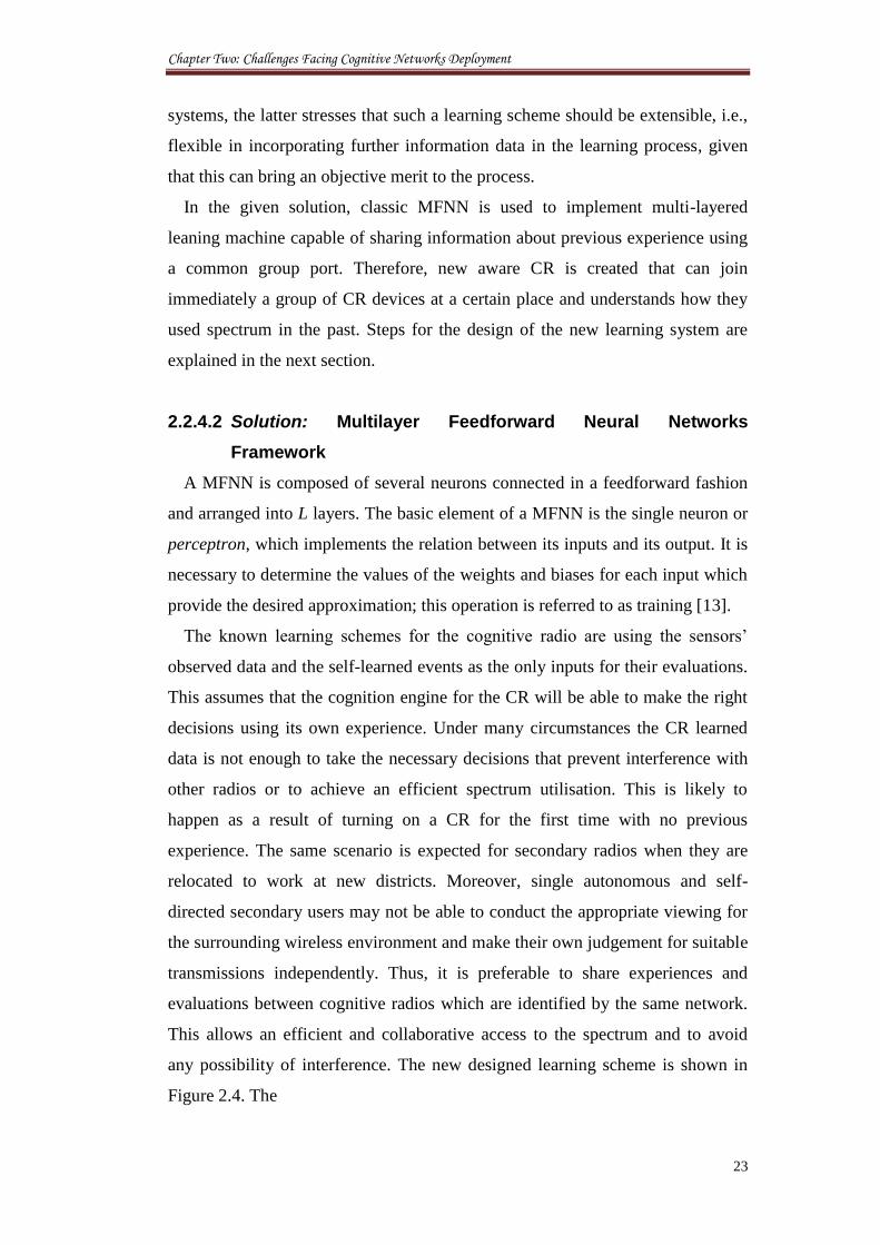
Chapter Two: Challenges Facing Cognitive Networks Deployment
23
systems, the latter stresses that such a learning scheme should be extensible, i.e.,
flexible in incorporating further information data in the learning process, given
that this can bring an objective merit to the process.
In the given solution, classic MFNN is used to implement multi-layered
leaning machine capable of sharing information about previous experience using
a common group port. Therefore, new aware CR is created that can join
immediately a group of CR devices at a certain place and understands how they
used spectrum in the past. Steps for the design of the new learning system are
explained in the next section.
2.2.4.2 Solution: Multilayer Feedforward Neural Networks
Framework
A MFNN is composed of several neurons connected in a feedforward fashion
and arranged into L layers. The basic element of a MFNN is the single neuron or
perceptron, which implements the relation between its inputs and its output. It is
necessary to determine the values of the weights and biases for each input which
provide the desired approximation; this operation is referred to as training [13].
The known learning schemes for the cognitive radio are using the sensors’
observed data and the self-learned events as the only inputs for their evaluations.
This assumes that the cognition engine for the CR will be able to make the right
decisions using its own experience. Under many circumstances the CR learned
data is not enough to take the necessary decisions that prevent interference with
other radios or to achieve an efficient spectrum utilisation. This is likely to
happen as a result of turning on a CR for the first time with no previous
experience. The same scenario is expected for secondary radios when they are
relocated to work at new districts. Moreover, single autonomous and self-
directed secondary users may not be able to conduct the appropriate viewing for
the surrounding wireless environment and make their own judgement for suitable
transmissions independently. Thus, it is preferable to share experiences and
evaluations between cognitive radios which are identified by the same network.
This allows an efficient and collaborative access to the spectrum and to avoid
any possibility of interference. The new designed learning scheme is shown in
Figure 2.4. The
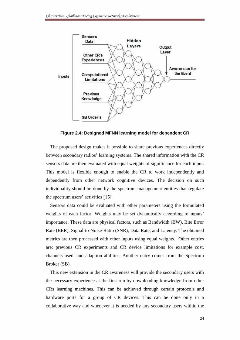
Chapter Two: Challenges Facing Cognitive Networks Deployment
24
Figure 2.4: Designed MFNN learning model for dependent CR
The proposed design makes it possible to share previous experiences directly
between secondary radios’ learning systems. The shared information with the CR
sensors data are then evaluated with equal weights of significance for each input.
This model is flexible enough to enable the CR to work independently and
dependently from other network cognitive devices. The decision on such
individuality should be done by the spectrum management entities that regulate
the spectrum users’ activities [15].
Sensors data could be evaluated with other parameters using the formulated
weights of each factor. Weights may be set dynamically according to inputs’
importance. These data are physical factors, such as Bandwidth (BW), Bite Error
Rate (BER), Signal-to-Noise-Ratio (SNR), Data Rate, and Latency. The obtained
metrics are then processed with other inputs using equal weights. Other entries
are: previous CR experiments and CR device limitations for example cost,
channels used, and adaption abilities. Another entry comes from the Spectrum
Broker (SB).
This new extension in the CR awareness will provide the secondary users with
the necessary experience at the first run by downloading knowledge from other
CRs learning machines. This can be achieved through certain protocols and
hardware ports for a group of CR devices. This can be done only in a
collaborative way and whenever it is needed by any secondary users within the
Chapter Two: Challenges Facing Cognitive Networks Deployment
25
same network. Comparisons can always be made whenever requested to match
up to the way that other CRs understand an action. Final assessments are function
for all the inputs and the best evaluated learning conclusions. It is similar to
someone who reads a book on history and learns from people who experienced
similar situations at similar times.
It is unreasonable to let the cognitive users in future to act without any
supervision from the spectrum management entities for example the SB. Such
monitoring will ensure the reliability of the secondary users’ system and prevent
the illegal usage of the spectrum. The decisions taken by these entities are also
fed for assessment in this proposed learning model. The final conclusions are
then sent to the decision makers. These modules are the states responsible for
running the CR and deciding the following actions of transmissions and
adaptions.
2.2.5 Dynamic Spectrum Access
Dynamic spectrum access is the process of increasing spectrum efficiency via
the real-time adjustment of radio resources; this is done via a process of local
spectrum sensing, probing, and the autonomous establishment of local wireless
connections among cognitive nodes and networks, as shown in Figure 2.5. As
originally proposed, cognitive radio is envisioned for real-time spectrum auctions
among diverse constituencies, used for one purpose, such as cellular radio,
spectrum allocation and public safety. These allow improving the resources
utilisation and increasing the revenues of trading the spectrum commercially
during peak periods.
Although that initial example has yet to be fully realised, the FCC encouraged
the application of that technology to the secondary use of underutilised television
spectrum, such as in ad hoc, short-range WLAN in the spectrum allocated to
another primary purpose, such as broadcast television. In addition, the principles
of cognitive radio for dynamic spectrum access also apply to enhance the
efficiency of use within and across each “lane in the road,” such as via the
intelligent selection among multiple alternative PHY-MAC layers (alternative
lanes in the spectrum road) by cognition across network, transport, and
application layers of the protocol stack [16].
Chapter Two: Challenges Facing Cognitive Networks Deployment
26
Figure 2.5: CR adaptations between various transmission opportunities
Wireless implementation of Dynamic Spectrum Access (DSA) in cognitive
networks requires:
Knowledge of available spectrum through wide-band spectrum
sensing, policies, changes in the spectrum availability.
Real-time spectrum management, provisioning and release of radio
bandwidth.
Network infrastructure and/or endpoints that support these
technologies and actions.
Thus, wireless DSA networks may require “new architectures and associated
signalling and control protocols” for their real-time spectrum management
component [17].
2.3 Network Planning
The end goal of this thesis is to propose practical planning for the CRN
infrastructure and resource allocation with the view of: improving the spectral
Chapter Two: Challenges Facing Cognitive Networks Deployment
27
efficiency, and maintain reliable high QoS cognitive communications which will
thus be our main figure of merit. In order to characterise the performance limit of
such systems, the criterion is set to be directly dependent on the application
requirements. Therefore, in order to design relevant network infrastructure for
real-time service, it is necessary to identify the network connectivity as a
function to the primary user activities [18].
Although most of the research works are focused on the spectrum sensing and
access methods, network capacity analysis is also an important research topic of
cognitive networks. For example, the optimal capacity value is the upper bound
of the network bandwidth which provides an ideal comparison value for different
channel allocation algorithm. Another important motivation is for the network
planning when considering different nodes’ density and traffic demands. Even in
network layer, the capacity of a specific route is crucial to provide an ideal index
for the design of routing algorithm. In the cognitive network, the significance of
network capacity is more important. First of all, primary users are strictly
undisturbed by secondary users, the extent that secondary users can access the
temporal available channels needs to be calculated. Then the spectrum allocation
algorithm will have an upper bound for comparison [19].
Consider a TV station which broadcasts in a currently licensed and exclusive
band. Despite the high prices paid for these exclusive bands in spectral auctions,
measurements show that white space, or temporarily unused time or frequency
slots, are alarmingly common. Notably, TV bands are wasted in geographic
locations barely covered by the TV signal. This has prompted various regulatory
and legislative bodies to put forth procedures which would open up TV channels
2-51 (54 MHZ - 698 MHz) for use by secondary devices. These devices, often
cognitive radios would be able to dynamically access the spectrum provided any
degradation they cause to the primary license holders’ transmissions is within an
acceptable level [20]. However, major interruption in cognitive services is
expected when the band is used by the PRs. This represents the worst case of
outage probability for CRN [21]. The most probable situation is a major increase
in the time required for a packet delivery over dynamic spectrum availability in
coexistence with the primary user [22].
In what follows, known cognitive network’s architectures are studied with the
challenges that face each of them to motivate the development of our
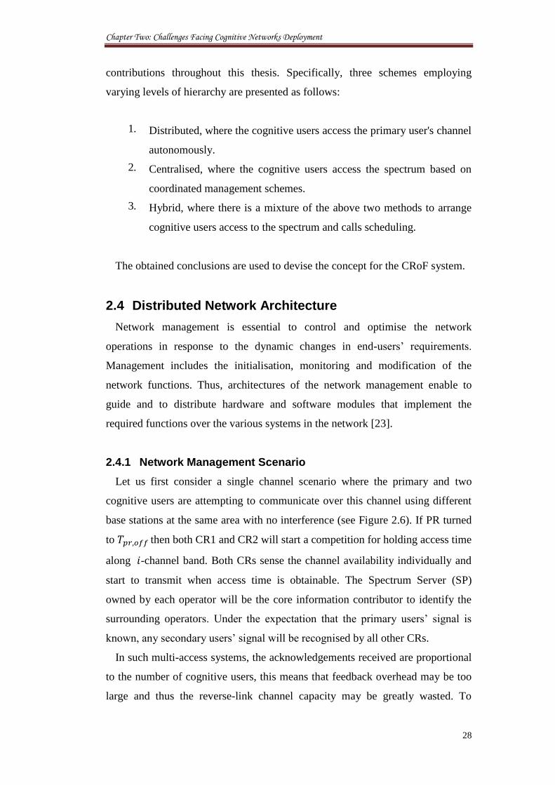
Chapter Two: Challenges Facing Cognitive Networks Deployment
28
contributions throughout this thesis. Specifically, three schemes employing
varying levels of hierarchy are presented as follows:
1. Distributed, where the cognitive users access the primary user's channel
autonomously.
2. Centralised, where the cognitive users access the spectrum based on
coordinated management schemes.
3. Hybrid, where there is a mixture of the above two methods to arrange
cognitive users access to the spectrum and calls scheduling.
The obtained conclusions are used to devise the concept for the CRoF system.
2.4 Distributed Network Architecture
Network management is essential to control and optimise the network
operations in response to the dynamic changes in end-users’ requirements.
Management includes the initialisation, monitoring and modification of the
network functions. Thus, architectures of the network management enable to
guide and to distribute hardware and software modules that implement the
required functions over the various systems in the network [23].
2.4.1 Network Management Scenario
Let us first consider a single channel scenario where the primary and two
cognitive users are attempting to communicate over this channel using different
base stations at the same area with no interference (see Figure 2.6). If PR turned
to then both CR1 and CR2 will start a competition for holding access time
along -channel band. Both CRs sense the channel availability individually and
start to transmit when access time is obtainable. The Spectrum Server (SP)
owned by each operator will be the core information contributor to identify the
surrounding operators. Under the expectation that the primary users’ signal is
known, any secondary users’ signal will be recognised by all other CRs.
In such multi-access systems, the acknowledgements received are proportional
to the number of cognitive users, this means that feedback overhead may be too
large and thus the reverse-link channel capacity may be greatly wasted. To
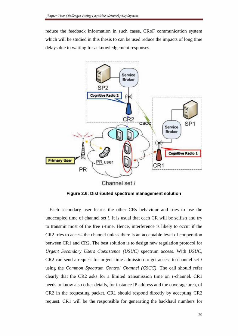
Chapter Two: Challenges Facing Cognitive Networks Deployment
29
reduce the feedback information in such cases, CRoF communication system
which will be studied in this thesis to can be used reduce the impacts of long time
delays due to waiting for acknowledgement responses.
Figure 2.6: Distributed spectrum management solution
Each secondary user learns the other CRs behaviour and tries to use the
unoccupied time of channel set . It is usual that each CR will be selfish and try
to transmit most of the free -time. Hence, interference is likely to occur if the
CR2 tries to access the channel unless there is an acceptable level of cooperation
between CR1 and CR2. The best solution is to design new regulation protocol for
Urgent Secondary Users Coexistence (USUC) spectrum access. With USUC,
CR2 can send a request for urgent time admission to get access to channel set
using the Common Spectrum Control Channel (CSCC). The call should refer
clearly that the CR2 asks for a limited transmission time on -channel. CR1
needs to know also other details, for instance IP address and the coverage area, of
CR2 in the requesting packet. CR1 should respond directly by accepting CR2
request. CR1 will be the responsible for generating the backhaul numbers for
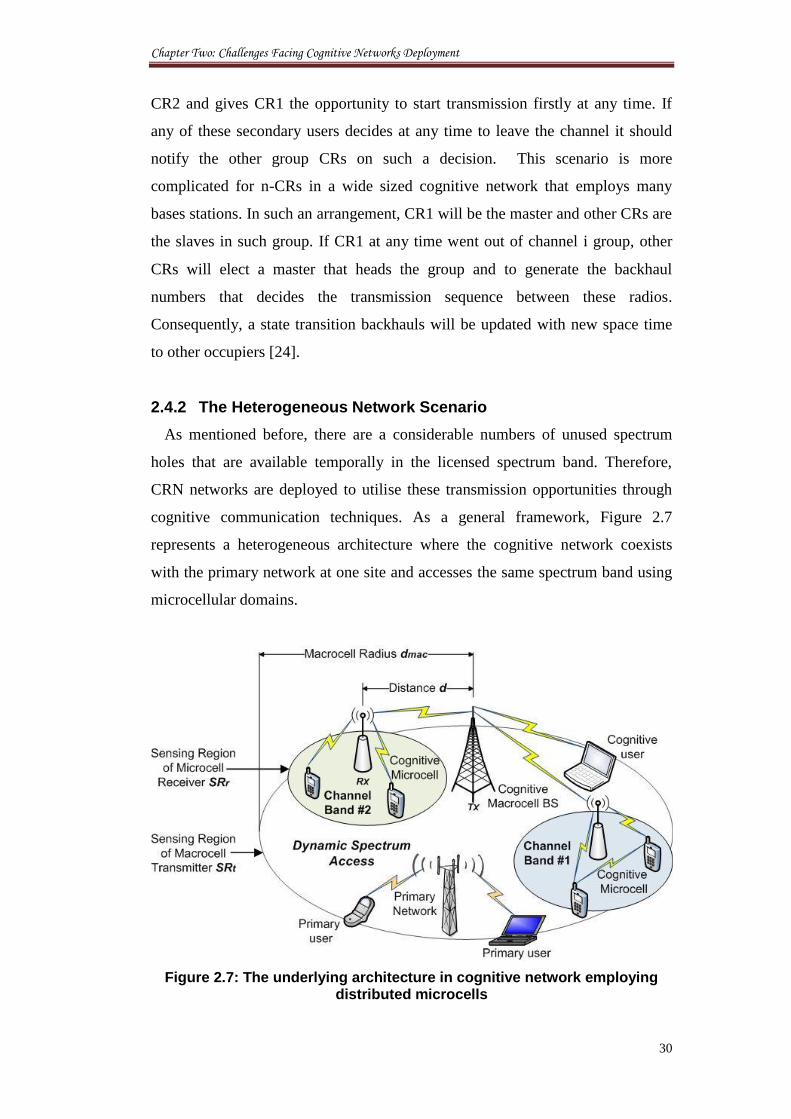
Chapter Two: Challenges Facing Cognitive Networks Deployment
30
CR2 and gives CR1 the opportunity to start transmission firstly at any time. If
any of these secondary users decides at any time to leave the channel it should
notify the other group CRs on such a decision. This scenario is more
complicated for n-CRs in a wide sized cognitive network that employs many
bases stations. In such an arrangement, CR1 will be the master and other CRs are
the slaves in such group. If CR1 at any time went out of channel group, other
CRs will elect a master that heads the group and to generate the backhaul
numbers that decides the transmission sequence between these radios.
Consequently, a state transition backhauls will be updated with new space time
to other occupiers [24].
2.4.2 The Heterogeneous Network Scenario
As mentioned before, there are a considerable numbers of unused spectrum
holes that are available temporally in the licensed spectrum band. Therefore,
CRN networks are deployed to utilise these transmission opportunities through
cognitive communication techniques. As a general framework, Figure 2.7
represents a heterogeneous architecture where the cognitive network coexists
with the primary network at one site and accesses the same spectrum band using
microcellular domains.
Figure 2.7: The underlying architecture in cognitive network employing distributed microcells
Chapter Two: Challenges Facing Cognitive Networks Deployment
31
The criterion for success in the CRN is to determine the best available
spectrum by detecting the presence of primary users. This becomes more
complicated in a dynamically changing wireless environment that employs
different technologies, operators, and users. The channel capacity of the
spectrum holes may change also as a function of the place of availability and
nearby primary users. As a secondary user, cognitive networks have to avoid
interference with primary users at all times. Furthermore, the cognitive users
should vacate the current channel and move to the new channel immediately,
whenever the primary users return to transmit; this is called spectrum handover.
In the above architecture, the available spectrum band is sliced by creating small
transmission domains of cognitive networks. This multi-access system allows
better coexistence and spectrum trade between primary and cognitive users. Such
an accurate modelling of the cognitive network infrastructure is a key to
understand the actual advantages brought by secondary users. It can be noticed
that the system model presented in this section is related to a single operator
model; however, modelling is also applicable to heterogeneous model case as
well. The challenge here is to set the hierarchical modelling of spectrum access
authentication and the necessary power adaptations between various wireless
domains. The goal is to prevent multiple access points from interfering each
other and the main LTE macrocell base station.
2.4.3 System Model
A key factor for the mesh-cognitive radio networks is the establishment of link
path connections between many base stations. This demands the availability of
free spectrum channels at all domain sites that a link is passing through. The
spectrum unavailability at one or more sites can cause major interruptions in the
secondary network services. This spectrum unavailability can be resulted from
[25]:
The absence of some operational cognitive nodes along a trajectory
between two points when the primary users occupy the entire
spectrum band. This blocks the cognitive stations for unpredicted
time periods until spectrum ‘white spaces’ are revealed again.
Chapter Two: Challenges Facing Cognitive Networks Deployment
32
Cognitive base stations may become selfish and ignore the requests
to formulate links with other neighbouring stations. This behaviour
triggers a significant degradation in the performance of the
cognitive network especially if this action was spread across many
network sites.
Therefore, channel assignment algorithms used in cellular networks are not
applicable for cognitive radio networks. As the optimal channel assignment
problem in cognitive radio networks takes into account new factors like dynamic
spectrum allocation, new algorithms are required to enable flexibility in
accessing the spectrum and coexist with users at no interference. The problem is
extended further when considering the link quality constraints. The link quality
constraints refer to the signal-to-noise ratio or the distance ratio for using a
channel, while fairness refers to equally distribution of the available channels to
users in operation.
2.5 Centralised Network Management
2.5.1 Joint Spectrum Allocation
In realistic applications, the centralised network system is hard to implement.
All primary and secondary operators should be connected to the SB.
Consequently, it is mandatory for any CR, which intends to transmit at any
channel to get the SB approval. This process is performed using the hierarchal
levels shown in Figure 2.8. A request for transmission is initially passed by a CR
to the Service Manager (SM) in the operator and then to the SB. The broker acts
as the main complementary provider for information gained from networks’
sensors and service managers in operators. The SB will then undertake the
necessary arrangements to allocate the usage time for multi-users that intend to
share -channel set. SB generates the backhaul link necessary for intermediate
fairly sharing of the available time among secondary users. While this seems to
be an effortless way to share one channel, the time engaged for processing the
CRs’ request is significant and may cause the waste of pricey time during
processing at any various system levels. However, such a system may be the best
to avoid interference between CR users themselves or CR and primary users.
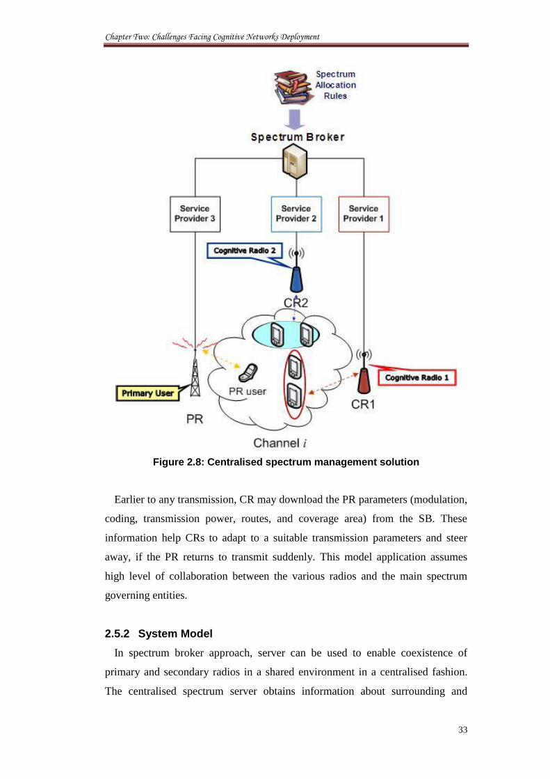
Chapter Two: Challenges Facing Cognitive Networks Deployment
33
Figure 2.8: Centralised spectrum management solution
Earlier to any transmission, CR may download the PR parameters (modulation,
coding, transmission power, routes, and coverage area) from the SB. These
information help CRs to adapt to a suitable transmission parameters and steer
away, if the PR returns to transmit suddenly. This model application assumes
high level of collaboration between the various radios and the main spectrum
governing entities.
2.5.2 System Model
In spectrum broker approach, server can be used to enable coexistence of
primary and secondary radios in a shared environment in a centralised fashion.
The centralised spectrum server obtains information about surrounding and
Chapter Two: Challenges Facing Cognitive Networks Deployment
34
interference through local measurements from different terminals and then offer
suggestions to the efficient spectrum use. Service providers and users of the
networks do not a priori own any spectrum; instead they obtain time bound rights
from a regional spectrum broker to a part of the spectrum and configure it to
offer the network service [26].
The main purpose of the SB is to achieve minimum connection blocking
probability through optimally controlled dynamic spectrum access. Therefore, it
is reasonable to have low- and high-priority spectrum users. The highest priority
is always assigned to the licensed users. The prioritisation between two
unlicensed users should include the minimum guard band. Hence, the number of
transmission admissions accepted from unlicensed users should not exceed the
number of free channels at a time period. This is a great task for the success of
cognitive networks that employ centralised spectrum sharing fashion models.
This growing numbers of calls against fewer numbers of transmission
opportunities will lead to incredible numbers of declined calls and blocked
connections. This situation may become worse with so many systems approach
the SB at one time. The time consumed to contact the SB, getting temporary
access licence and then performing adaptation to access certain channel may
cause missing so scarce transmission opportunities. Therefore, it is necessary to
understand the type of services expected from a SB as a function to the network
size and white spectrum in order to reduce any complexity or disturbance. This
can be done while deploying new networks or planning any modifications for the
functioning of the management of the network. It is also very important to
understand the type of authority given to the various SBs for being local,
regional, or even international. Additionally, what sort of SBs connections in
place and if they are connected to either primary and secondary networks or just
the cognitive network.
2.6 Hybrid Network Management
2.6.1 Overview
Both the above scenarios centralised and distributed are bridged together to
create a new hybrid spectrum sharing management. In this model, if CR2 intends
to transmit on channel set , it sends a request to the spectrum broker. The SB, as
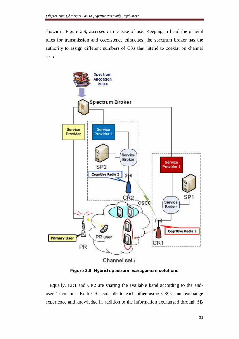
Chapter Two: Challenges Facing Cognitive Networks Deployment
35
shown in Figure 2.9, assesses -time ease of use. Keeping in hand the general
rules for transmission and coexistence etiquettes, the spectrum broker has the
authority to assign different numbers of CRs that intend to coexist on channel
set .
Figure 2.9: Hybrid spectrum management solutions
Equally, CR1 and CR2 are sharing the available band according to the end-
users’ demands. Both CRs can talk to each other using CSCC and exchange
experience and knowledge in addition to the information exchanged through SB
Chapter Two: Challenges Facing Cognitive Networks Deployment
36
link. Once the users have been set by the SB, one of those CRs will be the master
and the other is slave. The senior -user is to head all other n-secondary radios
for its long experience on the channel band. Therefore, spectrum access activities
are managed by CR1 along with negotiations between all CR set, while all
updates should be passed to the SB by the master. This will allow the SB to deal
with other operator matters and to vacate the information channels for other
users.
When any of the CRs leaves the channel set , the senior CR informs the SB
and a new sequence for using the spectrum is generated immediately to assure
efficient usage and fairness between different users. This scenario is more
compatible for future heterogeneous networks where flexible DSA is required to
achieve robust usage for scarce spectrum.
2.6.2 System Model
The main challenges here are how to plan this kind of network and configure
various domains to optimise the available spectrum holes. The EU FP7-E3
project investigates and defines solutions for managing and controlling
interoperability, scalability and flexibility in wireless networks. These solutions
had taken into account both the BSs, as well as the core network elements
providing the end-to-end service (e.g. gateways, access controllers,
authentication servers) [27].
In our model, we focus on the channel selection for the network access points.
Therefore, we assume that a cognitive Access Point (AP) has the ability to
sample the available spectrum transmission opportunities and periodically adapt
according to the spectrum dynamic changes and traffic. Therefore, the activity of
a given channel is defined as the mean number of frame transmissions occurred,
averaged across all sample durations within a particular time. Cumulative
activity of a channel not only represents the activity of a particular channel, but
also considers the activity in other overlapping channels. For example, the
cumulative activity is estimated by the following equation [28]:
∑
Chapter Two: Challenges Facing Cognitive Networks Deployment
37
where represents the cumulative activity in channel , is the channel
overlap factor which in 802.11b is three, is the set of channels in the system
(set of channels 1 to 11 in 802.11b), is the activity in a given channel .
Therefore, the cumulative activity is the sum of the activities in the overlapping
neighbouring channels.
The cognitive network chooses the best possible channel based on the
following equation [28]:
2.6.3 Multi–hop Problem
A route discovery and formulation process has a different procedure in a
cognitive network than in other networks. An established link over many APs
may collapse due to dynamic wireless changes at different transmission domains.
One of the current suggested solutions involves ‘holding the data or simply
buffering them until re-stabilising the same route. Another solution is that a new
route can be discovered and created. Obviously, both of those operations will
cause considerable delays to network communications. Also, the buffering node
that holds the data at a certain location may be lost completely and
communications would not be recovered again for some time due to spectrum
unavailability. The other expected direct effects are: service interruption and
traffic congestion.
To explain this, let A, B, C, D, E, F, and G be the positions where the cognitive
BS nodes are positioned within a cognitive network as shown in Figure 2.10.
Each Node (N) is assigned to a certain wireless domain. A packet of data is
sent from A to E using route (1). Suppose that a sudden interruption in service
occurs at node C due to wireless changes at node D. Then, the holding delay time
resulting from buffering the packets at node C is derived as [21]:
where and are the time of packet arrival and leaving at Node C
respectively.
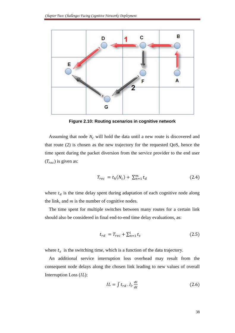
Chapter Two: Challenges Facing Cognitive Networks Deployment
38
Figure 2.10: Routing scenarios in cognitive network
Assuming that node will hold the data until a new route is discovered and
that route (2) is chosen as the new trajectory for the requested QoS, hence the
time spent during the packet diversion from the service provider to the end user
( ) is given as:
∑
where is the time delay spent during adaptation of each cognitive node along
the link, and is the number of cognitive nodes.
The time spent for multiple switches between many routes for a certain link
should also be considered in final end-to-end time delay evaluations, as:
∑
where is the switching time, which is a function of the data trajectory.
An additional service interruption loss overhead may result from the
consequent node delays along the chosen link leading to new values of overall
Interruption Loss ( ):
∫
Chapter Two: Challenges Facing Cognitive Networks Deployment
39
where is the service interruption loss per cell.
As a result, the possibility of route collapse ( ) is increased due to the
growth in the time delays overhead. This relation is applicable mainly for long
routes passing through wireless congested areas. Therefore, the probability of
link collapse can be written as:
where represents the call duration.
2.7 Cooperative and non-Cooperative Spectrum Sharing
The fact that there are no access priorities between various cognitive users who
are accessing the same band of channels raise an important point for discussion
about the level of cooperation required between them during call admission. The
cooperation can be expressed in terms of exchanging information about
interference measurements, compliance with predetermined spectrum policy
rules and/or willingness for individual performance degradation. On the one
hand, there are approaches that assume full cooperation of the entities sharing the
spectrum [29]. A common technique used in these schemes is forming clusters to
share interference information locally. This localised operation provides an
effective balance between a fully centralised and a distributed scheme [30]. Such
a scheme can be applied for mesh networks where the mesh router and the mesh
clients supported by it form a cluster. Here, the mesh clients send their individual
sensing results to the mesh router, which are then combined to get the final
sensing result. For cognitive ad-hoc networks, where no central network entity,
this cooperation should be implemented in a distributed manner [31].
The ability of a cognitive radio to adaptively switch between channels:
spectrum mobility offers tremendous scope to optimise performance. The
dynamic spectrum access is challenging in a distributed type network,
particularly when the devices lack cooperation. Game theory is a mathematical
framework that provides a natural platform to study the effects of players’
decision strategies and equilibrium solutions in a competitive environment with
limited resource constraints. In game theoretical analysis, the optimising
Chapter Two: Challenges Facing Cognitive Networks Deployment
40
parameter and the definition of utility function characterises the resulting
equilibrium solution, provided that they exist. Such a proposed game theoretic
distributed adaptive channel allocation scheme for cognitive radios is formulated
to capture selfish and cooperative behaviours of the players. Non-cooperative
channel allocation and load balancing algorithms and spectrum utilisation
maximisation are the main challenges in this type of communications. The
channel selection in a distributed non-cooperative type network is less explored
and the discrete nature of the problem makes it relatively difficult to model [32].
In the next chapters, this study propose to create a cooperative network model,
then analyse the performance once the network users and access cognitive radios
turn to the non-cooperative behaviour.
2.8 Conclusion
This chapter presents a comprehensive survey for the cognitive network
management models from the outage capacity and spectrum utilisation
perspectives. As for the network management aspect, most literature explores the
known network architectures without identifying a key problem case to compare
performance metrics for successful network deployment. Thus, research on
network management needs to be extended to multi-user and/or multi-tier cell
cases as well as considering the practical issues, such as transmission-associated
availability of spectrum channels, which is of great significance to practical
system design. Regarding spectrum utilisation that will be used in future wireless
systems; existing research has shown that larger users’ services can be achieved
through efficient network design. The challenges proposed in this work are
necessary in order to investigate potential topics, such as those listed in this
chapter, as well as such originating from future wireless network models. The
novelty of this research is that it investigates the spectrum efficiency problem
through major changes in the network planning and installation. As the cognitive
network has not been deployed yet or commercially used, the novel given
approaches in this thesis can be initiated as a starting point to find the best
network planning architectures even before cognitive network starts. This helps
to save the cost of changing the network after deployment and use ant resources
efficiently at the first run time.
Chapter Two: Challenges Facing Cognitive Networks Deployment
41
2.9 References
[1] K. B. Letaief, and W. Zhang, “Cooperative Communications for Cognitive
Radio Networks”, Proceedings of IEEE, vol. 97, no. 5, 2009, pp. 878 -
893.
[2] Towards Cognitive Radio Systems. Main Findings from the COGNAC
project. M. Matinmikko and T. Bräysy (eds.). Espoo 2011. VTT Tiedotteita
- Research Notes 2575.
[3] K. C. Chen, Y. J. Peng, N. Prasad, Y. C. Liang, and S. Sun, “Cognitive
Radio Network Architecture: Part I - General Structure,” In proceedings of
the 2nd
International Conference on Ubiquitous Information Management
and Communication (ICUIMC’08), Malaysia, 2008.
[4] OFCOM, “Digital dividend: cognitive access, A Consultation on licence-
exempting cognitive devices using interleaved spectrum,” Technical
Report, 16th
Feb 2009.
[5] L. Hong-Jie, W. Zhong-Xu, L. Shu-Fang, and Y. Min, “Study on the
performance of spectrum mobility in cognitive wireless network,” In
proceedings of the 11th
IEEE Singapore International Conference on
Communication Systems (ICCS 2008), Guangzhou, China, 2008, pp.1010 -
1014.
[6] Q. H. Mahmoud, Cognitive Networks towards Self-Aware Networks, John
Wiley & Sons Ltd, Chichester, England, 2007.
[7] G. Bansal, M. Hossain, P. Kaligineedi, H. Mercier, C. Nicola, U. Phuyal,
M. Rashid, K.C. Wavegedara, Z. Hasan, M. Khabbazian, and V. K.
Bhargava, “Some Research Issues in Cognitive Radio Networks”, In
proceedings of the (AFRICON 2007), 2007, pp. 1 - 7.
[8] A. Ghasemi and E. S. Sousa, “Spectrum sensing in cognitive radio
networks: the cooperation-processing tradeoff,” Wireless Communications
and Mobile Computing, Special Issue: Cognitive Radio, Software Defined
Radio and Adaptive Wireless Systems, vol. 9, no. 7, 2007, pp. 1049 - 1060.
[9] K. Po and J. Takada, “Signal Detection based on Cyclic Spectrum
Estimation for Cognitive Radio in IEEE 802.22 WRAN System,” IEICE
Tech. Rep., vol. 106, no. 558, 2007, pp. 15 - 19.
Chapter Two: Challenges Facing Cognitive Networks Deployment
42
[10] A. Al-Dulaimi, N. Radhi, and H. S. Al-Raweshidy, “Cyclostationary
Detection of Undefined Secondary Users,” In proceedings of the IEEE
International Conference and Exhibition on Next Generation Mobile
Applications, Services, and Technologies (NGMAST'09), Cardiff, 2009, pp.
230 - 233.
[11] N. S. Shankar, C. Cordeiro, and K. Challapali, “Spectrum agile radios:
utilization and sensing architectures,” In proceedings of the 1st IEEE
International Symposium on New Frontiers in Dynamic Spectrum Access
Networks (DySPAN 2005), Baltimore, USA, 2005, pp. 160 - 169.
[12] Z. Zhang and X. Xie, “Intelligent Cognitive Radio: Research on Learning
and Evaluation of CR Based on Neural Network”, In proceedings of the 5th
International Conference on Information and Communications Technology
(ICICT 2007), Cairo, Egypt, 2007, pp. 33 - 37.
[13] N. Baldo and M. Zorzi, “Learning and Adaptation in Cognitive Radios
using Neural Networks”, In proceedings of the 5th
IEEE Consumer
Communications and Networking Conference (CCNC 2008), Las Vegas,
USA, 2008, pp. 998 - 1003.
[14] K. Tsagkaris , A. Katidiotis, and P. Demestichas, “Neural network-based
learning schemes for cognitive radio systems”, Journal of Computer
Communications, vol. 31, no. 5, 2008, pp. 3394 - 3404.
[15] A. Al-Dulaimi and L. Al-Saeed, “An Intelligent Scheme for First Run
Cognitive Radios,” In proceedings of the IEEE International Conference
and Exhibition on Next Generation Mobile Applications, Services, and
Technologies (NGMAST'10), 2010, pp. 158 - 161.
[16] A. M. Wyglinski, M. Nekovee, Y. Thomas Hou, Cognitive Radio
Communications and Networks Principles and Practice, ELSEVIER Inc,
2010.
[17] I. Baldine, A. Bragg, G. Evans, and D. Stevenson, “Dynamic Spectrum
Management - Applying Optical Networking Techniques to Wireless DSA
Networks,” In proceedings of the 1st IEEE International Symposium on
Frontiers in Dynamic Spectrum Access Networks (DySPAN 2005),
Baltimore, USA, 2005, pp. 615 - 618.
Chapter Two: Challenges Facing Cognitive Networks Deployment
43
[18] A. Abbagnale and F. Cuomo, “Leveraging the Algebraic Connectivity of a
Cognitive Network for Routing Design,” IEEE Transactions on Mobile
Computing, vol. 11, no. 7, 2011, pp. 1163 - 1178.
[19] H. Gang, L. Lixia, L. Hongjian, P. Deming, and X. Ming, “A Distributed
Capacity Estimation Algorithm of Cognitive Network,” In proceedings of
the 4th
Intentional Conference on Communications and Networking in
China (ChinaCOM 2009), China, 2009, pp. 1 - 5.
[20] M. Vu, N. Devroye, and V. Tarokh, “On the Primary Exclusive Region of
Cognitive Networks,” IEEE Transactions on Wireless Communications,
vol. 8, no. 7, 2009, pp. 3380 - 3385.
[21] A. Al-Dulaimi, S. Al-Rubaye, and H. S. Al-Raweshidy, “Renovate
Cognitive Networks under Spectrum Unavailability,” In proceedings of the
6th
Advanced International Conference on Telecommunications (AICT
2010), Spain, 2010, pp. 41 - 45.
[22] S. Zaidi, D. McLernon, and M. Ghogho, “Outage Probability Analysis of
Cognitive Radio Networks Under Self-Coexistence Constraint,” In
proceedings of the 4th
Annual Conference on Information Sciences and
Systems (CISS 2010), New Jersey, USA , 2010, pp. 1 - 6.
[23] A. Pras, “Network Management Architectures,” Thesis University of
Twente, The Netherlands, 1995.
[24] A. Al-Dulaimi and H. Al-Raweshidy, “Multi-Operator Cognitive Radios
Sharing One Channel”, In proceedings of the 7th
ACM international
symposium on Mobility management and wireless access (MobiWac’09),
Tenerife, Spain, 2009, pp. 114 - 117.
[25] A. Anand and R. Chandramouli, “Resource Allocation in Cognitive Radio
Networks,” in Y. Xiao and F. Hu (Eds.), Cognitive Radio Networks, CRC
Press, Jan. 2009.
[26] Ž. Tabaković, “A Survey of Cognitive Radio Systems”, Internet:
www.fer.unizg.hr/_download/repository/KDI_Tabakovic_Zeljko.pdf:
Accessed: June, 28, 2012.
[27] Z. Feng et al. “Requirements for Collaborative Cognitive RRM,” End-to-
End Efficiency - E3, E3_WP3_D3.1_080725.doc, 2008.
Chapter Two: Challenges Facing Cognitive Networks Deployment
44
[28] B. S. Manoj, R.R. Rao, and M. Zorzi, “Architectures and Protocols for
Next Generation Cognitive Networking,” in F. H. P. Fitzek and M. D. Katz
(Eds.), Cognitive Wireless Networks, Springer, 2007, pp. 271 - 284.
[29] K. V. Katsaros, P. A. Frangoudis, G. C. Polyzos, and G. Karlsson, “Design
challenges of open spectrum access,” In proceedings of the 19th
IEEE
International Symposium on Personal, Indoor and Mobile Radio
Communications (PIMRC 2008), French Riviera, France, 2008, pp. 1 - 5.
[30] I. F. Akyildiz, W. Y. Lee, M. C. Vuran, and S. Mohanty, “A survey on
spectrum management in cognitive radio networks,” IEEE
Communications Magazine, vol. 46, no. 4, 2008, pp. 40 - 48.
[31] I. F. Akyildiz, W. Y. Lee, and K.R Chowdhury, “CRAHNs: Cognitive
radio ad hoc networks,” Ad Hoc Networks, vol. 7, no. 5, 2009, pp. 810 -
836.
[32] S. Subramani, T. Basar, S. Armour, D. Kaleshi, and F. Zhong,
“Noncooperative Equilibrium Solutions for Spectrum Access in Distributed
Cognitive Radio Networks,” In proceedings of the 3rd
IEEE Symposium on
New Frontiers in Dynamic Spectrum Access Networks (DySPAN 2008),
Chicago, USA, 2008, pp. 1 - 5.
Chapter Three: Cognitive Radio over Fibre for Microcellular Applications
45
Chapter 3
Cognitive Radio over Fibre and
Uplink Capacity for
Microcellular Applications
3.1 Inrtoducation
In a two-tier cognitive network employing Orthogonal Frequency-Division
Multiplexing (OFDM) transmissions with universal frequency reuse, spectrum
pooling causes very different outage performances. This chapter presents the
design of system architecture of flexible access algorithms and schemes. The
spectrum-sharing problem is formulated towards an optimal scheme that
allocates the band channels locally to the secondary network various
transmission domains. Firstly, this chapter presents the network installation
model and radio access technologies used throughout most of this thesis. Both
new CRoF network and traditional CR network architectures are considered for
which the primary and the cognitive users wish to communicate, subject to
variable transmission intervals. Then, a mathematical model is introduced to
evaluate the bandwidth savings gained from the using of access system supported
fibre network. The new system incorporates access points at microcells and
distributed interworking network using topology and wireless interfacing
modifications to improve spectrum utilisation and minimise service
disconnectivity. Extensive simulations proved that the proposed CRoF models
show an improved performance compared with the existing cognitive network
schemes that ignore fibre connections.
Chapter Three: Cognitive Radio over Fibre for Microcellular Applications
46
3.2 Motivation
Cognitive Mesh Networks (CMNs) are presented as a future solution for
cellular communications due to the impending spectrum crunch. The spectrum
availability is analysed as the main barrier against the success of CMNs using
temporarily transmissions. Thus, CRoF is proposed as a solution for small
enterprise microcells services in CMNs. The CRoF architecture is based on using
the RoF to connect cognitive BSs. The vision for deployment assumes that CRoF
stations are positioned inside the primary macrocell coverage areas and in
coexistence with the primary Base Stations. Accordingly, CRoF would be able to
utilise local spectrum holes efficiently and provide higher throughput to
secondary users through trade-off of specific channels at certain domains. As a
result, new resource management of multi-microcellular-base stations are
proposed as a key development of cognitive, heterogeneous backbone wireless
systems. Thus, a network operator will be able to dynamically adapt the spectrum
occupation strategy and the choice of the suitable RATs depending on the
wireless environment changes and the services requested by the end-users. New
radio resource management strategies are developed on a time-variant network
side configuration as microcellular transmission domains. The objective is to
extend existing DSA in order to exploit heavily heterogeneous systems which are
based on collaborative and autonomous distributed decision-making principles.
Considering the scarce availability of radio resources and ease of deployment,
the same channel bandwidth was made available for all stations. The system
capacity in such a macrocell-microcell arrangement with shared spectrum is
determined by the local coverage of the macrocell and microcell transmission
domains, subject to an outage probability constraint per BS. The focus of the
research is to answer the following questions:
What is the two-tier uplink capacity in a typical macrocell with randomly
scattered microcells of the traditional and new proposed cognitive
network infrastructures, assuming a randomly distributed population of
actively transmitting users per tier domain?
Is it possible to accurately characterise the utilisation of local spectrum
transmission opportunities? How much benefit is accrued by macrocell
sectoring and time hopping cancellation using fibre network?
Chapter Three: Cognitive Radio over Fibre for Microcellular Applications
47
What is the difference between the various RAT in operation for
cognitive applications and adaptive coverage?
By addressing these questions, this work provides a comprehensive study for
the best network infrastructure management using capacity and time delay
evaluations in two-tiered cognitive network and in coexistence with primary
network. The final conclusions show that creating a suitable infrastructure using
CRoF can actually increase the uplink capacity for a shared spectrum network.
3.3 Related Work
The combination of cognitive microcells to the radio over fibre infrastructure
and the methodology for local resources allocations is uncovered problem area
for the 4G networks that employ secondary communications. Existing solutions
for addressing the local resources management in cognitive networks are
addressed in the following:
To overcome the drawback caused by the limited knowledge of network
topology and spectrum availability, all spectrum management functions are based
on cooperative operations, where CR users determine their actions based on
observed information exchanged with their neighbours. As an example,
Cognitive Radio Ad-Hoc Networks (CRAHNs) require assimilation of
information during sensing from several users to improve accuracy and for fair
sharing of the detected spectrum resource through cooperation [1].
Spectrum Assignment in Infrastructure has been used to improve the
performance of the network [2]. The authors suggested a new algorithm in order
to maximise the average bandwidth per flow, and avoid the spectrum waste by
idle secondary base stations. While, in [3], the authors proposed to transfer UWB
sensors data through radio over fibre for cognitive optical access networks
applications.
The Self-Organisation Network (SON) functionality includes all possible
technical functions that a network manages in an autonomous way. SON follows
the paradigm change for excellent network performance and operational
efficiency. The self-x framework is analysed as well as the problem statement
from several perspectives in terms of dynamic self-organised heterogeneous
Chapter Three: Cognitive Radio over Fibre for Microcellular Applications
48
wireless network segments, spectrum management, self-configuring protocol and
self-optimised network devices [4].
Resent work in Wireless LAN over Fibre (WLANoF) systems has developed a
centralised processing for the power of cognitive AP. The goal is to perform
dynamic radio resource management over a wide radio coverage area in order to
minimise the interference with other coexisting systems. The proposed cognitive
AP can provide a cost-effective and efficient method for devices to equally share
the Industrial, Scientific and Medical (ISM) radio bands by taking advantage of
cognitive radio ability in a collaborative way. This system is proposed for indoor
communications and looks into very short distances [5, 6].
In [7], authors have investigated the CRoF which are applied for microcells.
A combination of WLAN and RoF access points and WLAN bridges were
proposed to solve the problem of high end-users demands and spectrum
unavailability for future cognitive networks. Also, the CRoF was proposed as a
joint subnet in [8] to support wide-sized cognitive mesh networks. The
previous work done in [7] is developed by analysing more probable radio
access technologies for the CRoF deployed microcells.
3.4 Technical contributions
This work employs a framework for modelling the overall outage of spatial
distribution of cognitive microcells, in contrast to prior work [8, 9, 10, and 11].
Spectrum availability are likely to vary from one cell-site to another, and be
opportunistic rather than planned: Therefore a capacity analysis is set to show all
the dynamic changes across domains to provide more accurate results and more
plausible insights.
The mobile users’ locations are assumed to be randomly distributed as a
Homogeneous Spatial Poisson Point Process (SPPP) [12, 13, 14] within their
main transmitters’ domains. The three key contributions of this work are given
below:
First, robust network coexistence model is shown to enable two-tier
cognitive networks with universal frequency reuse to achieve higher user
capacity. With interference avoidance, an equitable distribution of users
Chapter Three: Cognitive Radio over Fibre for Microcellular Applications
49
between macrocell and microcell tiers is shown to be achieved with an
order-wise difference in the ratio of their coverage powers.
The CRoF concept for spectrum saving is based on the concept of
utilisation of an existing resource in the form of microcells connected
through radio over fibre. In such scenarios, the traffic is diverted through
landline in such a way that the diversion will not affect the user service
requirements. A mathematical model has been developed to estimate the
amount of spectrum that can be saved through CRoF. The model has
evaluated to demonstrate the percentage of spectrum that can be saved.
The spectrum thus saved can be used for increasing the number of mobile
users without any addition to the existing mobile network infrastructure.
Finally, additional network modelling scenarios using a combination of
microcells bridging and tier selection based microcells transmission
domains results in a flexible model of network deployment options. This
suggests that at least for small microcells sizes, time hopping, and cell
division offer the largest gains in user capacity for shared spectrum two-
tier networks.
3.5 System Model
3.5.1 Dynamic Spectrum Access for Cognitive Network
In this section, a spectrum sharing model is proposed between small different
transmission domains with spectrum pooling. To allow the secondary users to
access the licensed channels bands as one pool of spectrum, all secondary
networks are set to employ OFDM as the underlying physical-layer transmission
technique [15]. This enables the secondary networks to be highly flexible in
accessing the spectral gaps left by the primary users while they are offline.
OFDM modulation is proposed as the best option for such temporary rental
coordination as it makes it possible to leave a set of unused subcarriers to fill the
spectral gaps [16 - 18].
The fundamental design of OFDM spectrum pooling is to match the bandwidth
of one subband of the primary network with an integer number of subcarriers
used in secondary networks. Figure 3.1 shows an example of three subcarriers of
cognitive users that are using one licensed subband.
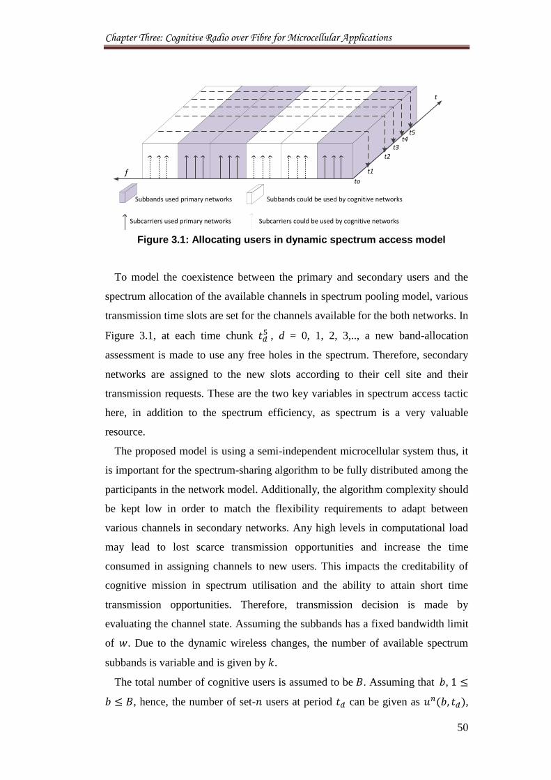
Chapter Three: Cognitive Radio over Fibre for Microcellular Applications
50
Subbands used primary networks Subbands could be used by cognitive networks
Subcarriers used primary networks Subcarriers could be used by cognitive networks
fto
t1
t2
t3t4
t5
t
Figure 3.1: Allocating users in dynamic spectrum access model
To model the coexistence between the primary and secondary users and the
spectrum allocation of the available channels in spectrum pooling model, various
transmission time slots are set for the channels available for the both networks. In
Figure 3.1, at each time chunk , d = 0, 1, 2, 3,.., a new band-allocation
assessment is made to use any free holes in the spectrum. Therefore, secondary
networks are assigned to the new slots according to their cell site and their
transmission requests. These are the two key variables in spectrum access tactic
here, in addition to the spectrum efficiency, as spectrum is a very valuable
resource.
The proposed model is using a semi-independent microcellular system thus, it
is important for the spectrum-sharing algorithm to be fully distributed among the
participants in the network model. Additionally, the algorithm complexity should
be kept low in order to match the flexibility requirements to adapt between
various channels in secondary networks. Any high levels in computational load
may lead to lost scarce transmission opportunities and increase the time
consumed in assigning channels to new users. This impacts the creditability of
cognitive mission in spectrum utilisation and the ability to attain short time
transmission opportunities. Therefore, transmission decision is made by
evaluating the channel state. Assuming the subbands has a fixed bandwidth limit
of . Due to the dynamic wireless changes, the number of available spectrum
subbands is variable and is given by .
The total number of cognitive users is assumed to be . Assuming that ,
, hence, the number of set- users at period can be given as ,
Chapter Three: Cognitive Radio over Fibre for Microcellular Applications
51
where , where represents the number of available service types. In
addition, is used to represent the number of subbands occupied by the
cognitive network base stations at period . Let denote the number of
free subbands in the spectrum pool at period and the arrival and departure
processes of mobile users in cognitive domains are assumed to be Poisson
process as in [15]. For network, the expected user arrival and departure rates of
set- users are represented by and
, respectively. In the same way,
the free spectrum holes arrival and departure processes are also assumed to
follow Poisson processes, with and as the expected arrival and departure
rates respectively.
3.5.2 Problem Solution for Spectrum Sharing
The spectrum sharing is formulated for the investigated models as a stochastic
process at which only one of the cognitive base stations is set to be active to
make use of the new available spectrum subband.
There are five expected network changes at any period , during
, where is the maximum number of periods considered in this analysis. These
are listed in Table 3.1 below.
Table 3.1: Transition States for Cognitive Network Spectrum Access
State Description
I, Cognitive base station starts transmitting
II, Cognitive base station stops transmitting
III, Spectrum subband becomes available to cognitive network
IV, Cognitive network losses a subband due to the primary network
returns to transmit
V, Cognitive users losses a suband due to clashes between various
domains transmissions
As there are no guarantees for the time of spectrum availability durations and
futuristic wireless changes from cognitive network prospective, the transmission
decision options at any time period is defined as:
Chapter Three: Cognitive Radio over Fibre for Microcellular Applications
52
In the studied coexistence models, one period of transmission is allocated for
each base station. This allows overcoming any probability of interference
occurrence between various spectrum users. This also subject to the decision of
transmission in place and is and the admissions of any new users. Final
transmission decisions are a function for the maximum number of users in
network and the maximum numbers of subcarriers that are available at a time
for network . The users’ admissions are modelled in this study as a random
process to allow a real representation of coexistence between primary and
secondary networks.
3.6 CRoF Framework
The concept of cognitive radio over fibre is presented in terms of network
model that incorporates different base stations at different levels with one main
processing unit. The method used assumes high level integration of units
provided by the necessary algorithms allow the functioning of the new system to
achieve the anticipated goals. The main goal is to access spectrum holes locally
and time-efficiently. Figure 3.2 shows the proposed framework for CRoF
multiple transmission two-tier cells. Without loss of generality, the system used
here has two cognitive microcells as an example to demonstrate the concept of
spatial accessing to the spectrum. For simplicity, the distance between these two
microcells are assumed to be long enough so that the interference effects are
negligible. Both microcells are connected by a radio over fibre to the main
CRoF-core without any packet loss and enough bandwidth for all transferred
packets through the landline connection. In the same way, the conversion time
for channel conditioning between wireless BSs and RoF is assumed to be much
lower than the propagation delays induced by the wired link.
The CRoF core functionality must be put in place to enable performing
identify function of the cognitive system. There are a number of methods
available to determine spectrum usage over a given band. These range from
energy detection to analyse the features of the signal of the primary users.
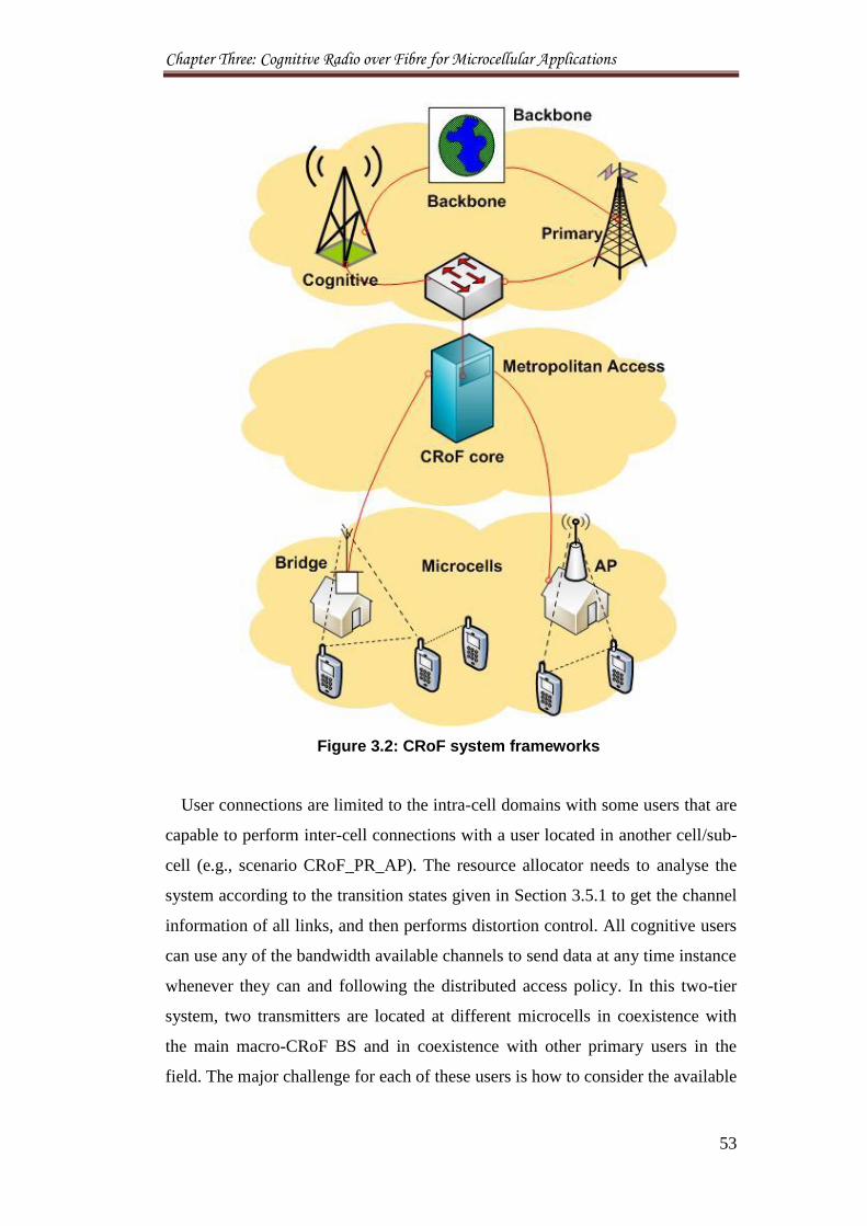
Chapter Three: Cognitive Radio over Fibre for Microcellular Applications
53
Figure 3.2: CRoF system frameworks
User connections are limited to the intra-cell domains with some users that are
capable to perform inter-cell connections with a user located in another cell/sub-
cell (e.g., scenario CRoF_PR_AP). The resource allocator needs to analyse the
system according to the transition states given in Section 3.5.1 to get the channel
information of all links, and then performs distortion control. All cognitive users
can use any of the bandwidth available channels to send data at any time instance
whenever they can and following the distributed access policy. In this two-tier
system, two transmitters are located at different microcells in coexistence with
the main macro-CRoF BS and in coexistence with other primary users in the
field. The major challenge for each of these users is how to consider the available
Chapter Three: Cognitive Radio over Fibre for Microcellular Applications
54
transmission opportunities and how to access resources to each user in each link
in order to maximise resources sharing.
Fibre optic radio access networks are optical backbone networks for radio
access systems, where fibre links have the function of transferring radio signals
into remote stations without destroying their radio format, such as RF,
modulation format, and so on [22]. Therefore, we propose the radio over fibre
landline connections as an alternative choice for replacing the wireless links of
the cognitive network. The combination of CR nodes to the RoF creates a new
type of reconfigurable bases stations namely CRoF. There is no development
made to the RoF as it is used only for connecting the CR BSs. On the other hand,
CR models are upgraded to include the fibre connections as an option in
communicating with other base stations. This new mesh CR-fibre system
simplifies the complexity of DSA by introducing a new scheme for spectrum
slicing and sharing based on local spectrum access. Therefore, instead of using
the traditional centralised, distributed, and hybrid network managements, CRoF
is the first secondary system wired with landline network. In addition to the
effective allocation for the available resources, the new proposed network model
reduces the time spent during service approval.
In CRoF network, BSs remain able to communicate with each other via
wireless connections. The actual role of the fibre here is to maintain connections
for spectrum unavailability, link budget, and fallen in QoS scenarios. Thus,
CRoF BSs behave as CR and CRoF models at the same time. One additional
advantage from using the fibre here is the spectrum savings gained from
transmitting using fibre connections rather than wireless links. As a result, the
CRoF frees up more resources for the cognitive network in a spectrum pool
model. This increases the cost effectiveness and the reliability of future cognitive
networks in maintaining communications in very dynamic wireless
environments.
The successful deployment of CRoF microcellular bases stations is a function
for the available free channels at the different cell sites, number of expected end-
users, and forecasted future demands and outcomes from cognitive
communications. The wide distribution of CRoF domains result in shorter
wireless links while BS-to-BS transmissions are directed through fibre
connections. Obviously, the cost of setting up is significantly impacts the
Chapter Three: Cognitive Radio over Fibre for Microcellular Applications
55
deployment sites if the new system. The throughput barriers for long routes,
discussed in Chapter 2, justify the need for CRoF system. Initially, the CRoF can
be proposed as a long term solution for cognitive networks in metropolitan areas.
The direct expected outcomes for CRoF installation are:
Increasing network capacity by freeing more links and channels across
the network for other cognitive radio operations.
Establishing new independent sub-network capable of supporting variable
downloading speeds for the secondary systems.
Avoiding overhead delays at high interruption loss.
New approach for green communications.
3.7 System Models
The adoption of RoF coupled with cognitive radio networks provided with
advanced interface radio access technologies can ease the traffic congestion
resulted from the spectrum unavailability. One of the main features of the CRoF
network is to efficiently use the underutilised resources of existing infrastructure
by diverting the transmissions between mobile and fibre networks in order to
recover services. This research quantifies the amount of spectrum that can be
saved from using fibre for intermediate communications between CR-BSs. A
spectrum saving model is introduced to analyse the increase in numbers of
subscribers in the cognitive network due to modifications in the infrastructure
that targets to improve the quality of service.
3.7.1 Call Diversion Algorithm
A method of diverting calls between BSs using fibre network is integrated to
CRoF system in order to interconnect various base stations to the CRoF core
unite. The algorithm assures the reliability of a call using the landline network.
To achieve this, call forwarding algorithm is activated to allow calls diversion
from/to a certain BS using fibre connections. In this way, any of the systems’
BSs can enable the call forwarding scheme if the dialled mobile phone is outside
the zone of their coverage area. This requires the identification of the target
mobile user position and the serving BS.
Chapter Three: Cognitive Radio over Fibre for Microcellular Applications
56
The forwarding location of the mobile call is determined using a mobile
location technology. The mobile location technology refers to the attaining of the
position of a mobile phone at a time whether it was stationary or moving.
Localization is performed via multilateration of Radio Frequency (RF) signals
between different BSs of the network and the mobile phone. This performed
through socialising that a mobile sends during roaming with the next nearby BS
with no need for any real active call. The measured signal strength allows
specification of the domain where that mobile phone exits at that time. The
mobile positioning, which includes location based service that discloses the
actual coordinates of a mobile phone, is very important for cognitive networks to
decide the channels allocated for communications and the spectrum savings
expected from using the call diversion scheme. Therefore, the more proper
locating scheme refers to the purpose rather than a positioning process. In this
model, the prior art of the call forwarding method at the BS is initialised once
and when the mobile user moves into its transmission domain. The proposed
scheme does not include any new functions with existing mobile phones and
does not require additional mobile phone hardware or software to implement.
Figure 3.3 shows the model of the remote command process for diverting calls
or messages between base stations. This is an algorithm that enables a CRoF core
to remotely command other BSs to divert calls or messages using fibre network
to the new mobile location. The algorithm is embedded in the CRoF core and all
BSs at the macrocellular and microcellular domains.
The scheme works as follows: in step #1, a mobile phone is starts moving
between CRoF domains. As the mobile phone starts the normal registration with
the nearest BS in #2, a remote command is forwarded by the BS to the CRoF
core for diverting calls to the newly registered mobile phone. Then this command
is set to OFF in #3 in waiting for CRoF core response.
Once it has been confirmed that the mobile phone is registered with the new
BS, the remote divert program in step #4 is initiated and starts running. Then, the
activated program will read and evaluate the mobile location in #5. The program
will check the mobile phone position if there are more than one request for
diversion which is issued from macro/micro CRoF-domain, in #6.
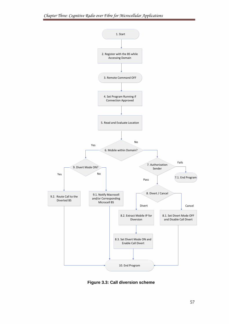
Chapter Three: Cognitive Radio over Fibre for Microcellular Applications
57
1. Start
2. Register with the BS while Accessing Domain
3. Remote Command OFF
4. Set Program Running if Connection Approved
5. Read and Evaluate Location
6. Mobile within Domain?
10. End Program
9.1. Notify Macrocell and/or Corresponding
Microcell BS
9.2. Route Call to the Diverted BS
8.1. Set Divert Mode OFF and Disable Call Divert
8.2. Extract Mobile IP for Diversion
8.3. Set Divert Mode ON and Enable Call Divert
9. Divert Mode ON?7. Authorization
Sender
8. Divert / Cancel
7.1. End Program
YesNo
Yes No
Fails
Pass
Divert Cancel
Figure 3.3: Call diversion scheme
Chapter Three: Cognitive Radio over Fibre for Microcellular Applications
58
When the CRoF core is not be able to identify the position of the mobile phone
especially if it was moving between two transmission domains, the program will
authenticate the sender as in #7, if this fails the program ends in #7.1. If the
authentication passes, the program will identify the command to either divert
calls of cancel diversion as in step #8. When cancel command is received, the
program will set the diversion mode to OFF and stops further diversions from
other BSs as in step #8.1. If the divert is approved, the program will extract the
mobile phone location as in #8.2. Then, a command is issued to set the diversion
mode ON and enable the diversion of calls to the mobile’s new location as in
step #8.3. The diversion of calls continue until further notification is received
from another BS that the mobile phone has moved into new domain then the
program starts again.
Once it has been confirmed that the mobile phone is registered with the new
BS, the remote divert program in step #4 is initiated and starts running. Then, the
activated program will read and evaluate the mobile location in #5. The program
will check the mobile users positions and if there are more than one request for
diversion which is issued from macro/micro CRoF-domain, in #6.
When the CRoF core is not be able to identify the position of the mobile phone
especially if it was moving between two transmission domains, the program will
authenticate the sender as in #7, if this fails the program ends in #7.1. If the
authentication passes, the program will identify the command to either divert
calls of cancel diversion as in step #8. When cancel command is received, the
program will set the diversion mode to OFF and stops further diversions from
other BSs as in step #8.1. If the divert is approved, the program will extract the
mobile phone location as in #8.2. Then, a command is issued to set the diversion
mode ON and enable the diversion of calls to the mobile’s new location as in
step #8.3. The diversion of calls continue until further notification is received
from another BS that the mobile phone has moved into new domain then the
program starts again. When mobile location is identified within one of the CRoF-
BSs, the divert mode is examined in #9 and all the calls are being routed to the
BS where the mobile user is registered in #9.2. Otherwise, macrocell and the
corresponding BSs are notified to allow direct connection between macrocellular
BS and mobile phone to overcome call latency as in #9.1. The program ends at
#10 and returns to #3.
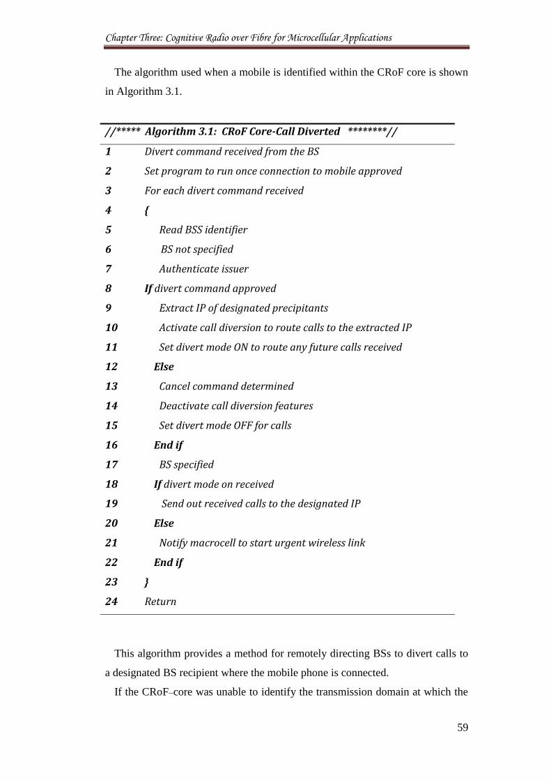
Chapter Three: Cognitive Radio over Fibre for Microcellular Applications
59
The algorithm used when a mobile is identified within the CRoF core is shown
in Algorithm 3.1.
//***** Algorithm 3.1: CRoF Core-Call Diverted ********//
1 Divert command received from the BS
2 Set program to run once connection to mobile approved
3 For each divert command received
4 {
5 Read BSS identifier
6 BS not specified
7 Authenticate issuer
8 If divert command approved
9 Extract IP of designated precipitants
10 Activate call diversion to route calls to the extracted IP
11 Set divert mode ON to route any future calls received
12 Else
13 Cancel command determined
14 Deactivate call diversion features
15 Set divert mode OFF for calls
16 End if
17 BS specified
18 If divert mode on received
19 Send out received calls to the designated IP
20 Else
21 Notify macrocell to start urgent wireless link
22 End if
23 }
24 Return
This algorithm provides a method for remotely directing BSs to divert calls to
a designated BS recipient where the mobile phone is connected.
If the CRoF–core was unable to identify the transmission domain at which the
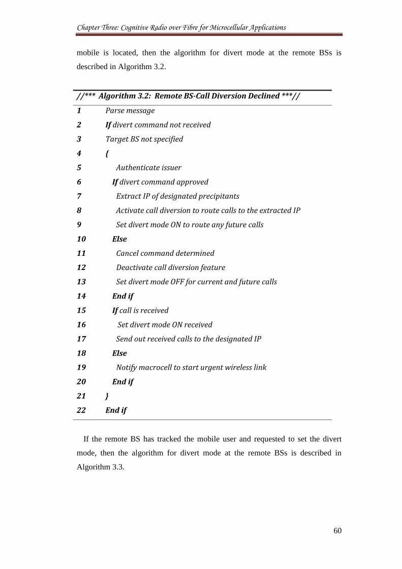
Chapter Three: Cognitive Radio over Fibre for Microcellular Applications
60
mobile is located, then the algorithm for divert mode at the remote BSs is
described in Algorithm 3.2.
//*** Algorithm 3.2: Remote BS-Call Diversion Declined ***//
1 Parse message
2 If divert command not received
3 Target BS not specified
4 {
5 Authenticate issuer
6 If divert command approved
7 Extract IP of designated precipitants
8 Activate call diversion to route calls to the extracted IP
9 Set divert mode ON to route any future calls
10 Else
11 Cancel command determined
12 Deactivate call diversion feature
13 Set divert mode OFF for current and future calls
14 End if
15 If call is received
16 Set divert mode ON received
17 Send out received calls to the designated IP
18 Else
19 Notify macrocell to start urgent wireless link
20 End if
21 }
22 End if
If the remote BS has tracked the mobile user and requested to set the divert
mode, then the algorithm for divert mode at the remote BSs is described in
Algorithm 3.3.
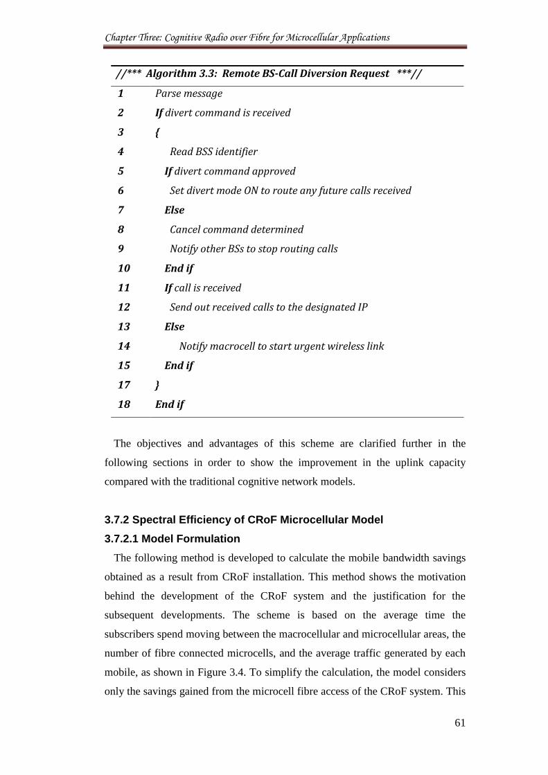
Chapter Three: Cognitive Radio over Fibre for Microcellular Applications
61
//*** Algorithm 3.3: Remote BS-Call Diversion Request ***//
1 Parse message
2 If divert command is received
3 {
4 Read BSS identifier
5 If divert command approved
6 Set divert mode ON to route any future calls received
7 Else
8 Cancel command determined
9 Notify other BSs to stop routing calls
10 End if
11 If call is received
12 Send out received calls to the designated IP
13 Else
14 Notify macrocell to start urgent wireless link
15 End if
17 }
18 End if
The objectives and advantages of this scheme are clarified further in the
following sections in order to show the improvement in the uplink capacity
compared with the traditional cognitive network models.
3.7.2 Spectral Efficiency of CRoF Microcellular Model
3.7.2.1 Model Formulation
The following method is developed to calculate the mobile bandwidth savings
obtained as a result from CRoF installation. This method shows the motivation
behind the development of the CRoF system and the justification for the
subsequent developments. The scheme is based on the average time the
subscribers spend moving between the macrocellular and microcellular areas, the
number of fibre connected microcells, and the average traffic generated by each
mobile, as shown in Figure 3.4. To simplify the calculation, the model considers
only the savings gained from the microcell fibre access of the CRoF system. This
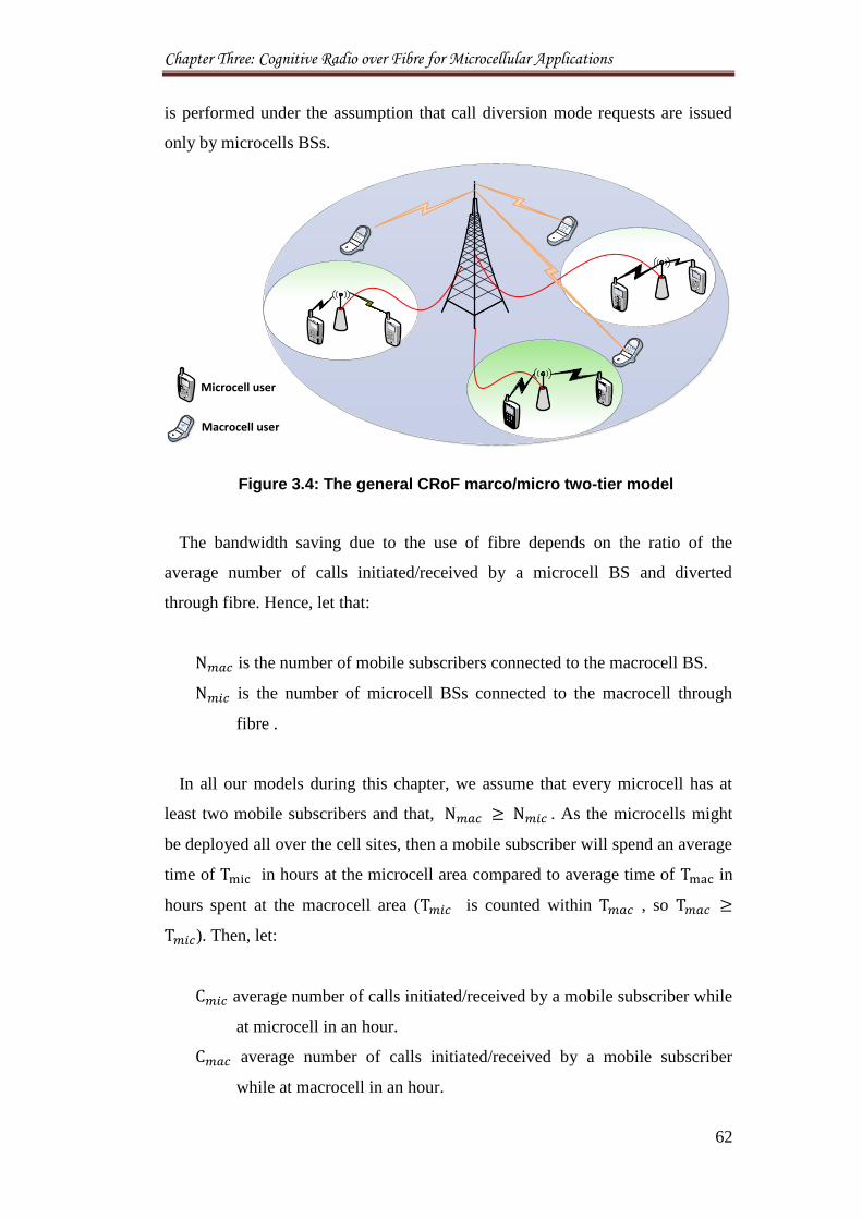
Chapter Three: Cognitive Radio over Fibre for Microcellular Applications
62
is performed under the assumption that call diversion mode requests are issued
only by microcells BSs.
Microcell user
Macrocell user
Figure 3.4: The general CRoF marco/micro two-tier model
The bandwidth saving due to the use of fibre depends on the ratio of the
average number of calls initiated/received by a microcell BS and diverted
through fibre. Hence, let that:
is the number of mobile subscribers connected to the macrocell BS.
is the number of microcell BSs connected to the macrocell through
fibre .
In all our models during this chapter, we assume that every microcell has at
least two mobile subscribers and that, . As the microcells might
be deployed all over the cell sites, then a mobile subscriber will spend an average
time of in hours at the microcell area compared to average time of in
hours spent at the macrocell area ( is counted within , so
). Then, let:
average number of calls initiated/received by a mobile subscriber while
at microcell in an hour.
average number of calls initiated/received by a mobile subscriber
while at macrocell in an hour.
Chapter Three: Cognitive Radio over Fibre for Microcellular Applications
63
number of peak hours over which the entire traffic initiated/received.
As the final values of calls in macrocell area include the calls made within
microcells, then . The number of calls initiated/received during
peak hour traffic by a mobile subscriber at CRoF microcell can be defined as:
The number of calls initiated/received during peak hours of traffic by a mobile
subscriber in the macrocell area is given by:
Then, the ratio of number of calls initiated/received during peak hours of
traffic by a mobile subscriber between microcells and macrocell base stations is
given by:
Assume that all calls received by mobile subscribers at microcell area are
diverted to macrocell via fibre then:
% of total spectrum saved in a microcell area through call diversion to fibre =
(
) (
) (
)
In the above analysis, uniform average calls duration for all categories of
subscribers has been assumed.
3.7.2.2 Model Evaluations
In order to verify the concept of increasing the network performance and
spectrum savings due to the use of microcells, the above mathematical model is
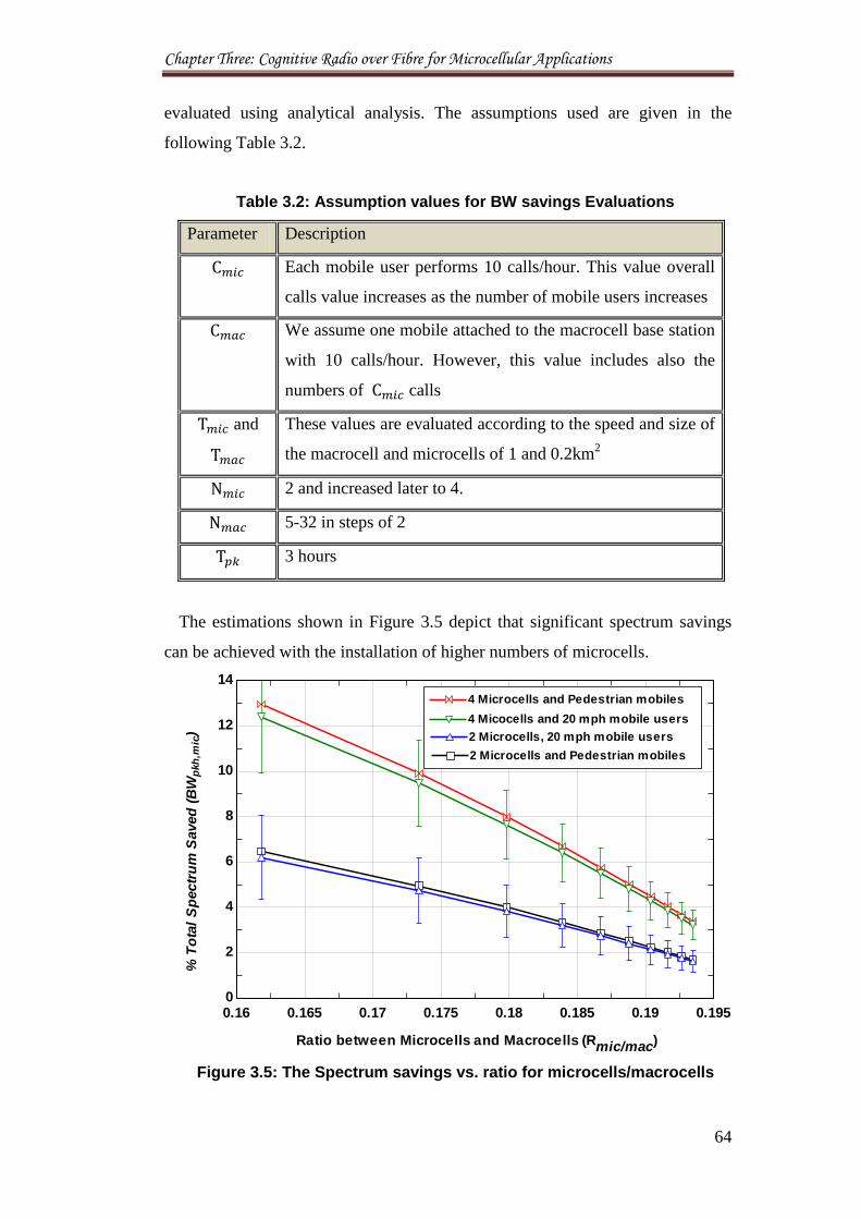
Chapter Three: Cognitive Radio over Fibre for Microcellular Applications
64
evaluated using analytical analysis. The assumptions used are given in the
following Table 3.2.
Table 3.2: Assumption values for BW savings Evaluations
Parameter Description
Each mobile user performs 10 calls/hour. This value overall
calls value increases as the number of mobile users increases
We assume one mobile attached to the macrocell base station
with 10 calls/hour. However, this value includes also the
numbers of calls
and
These values are evaluated according to the speed and size of
the macrocell and microcells of 1 and 0.2km2
2 and increased later to 4.
5-32 in steps of 2
3 hours
The estimations shown in Figure 3.5 depict that significant spectrum savings
can be achieved with the installation of higher numbers of microcells.
Figure 3.5: The Spectrum savings vs. ratio for microcells/macrocells
0.16 0.165 0.17 0.175 0.18 0.185 0.19 0.1950
2
4
6
8
10
12
14
Ratio between Microcells and Macrocells (Rmic/mac)
% T
ota
l S
pectr
um
Saved
(B
Wp
kh
,mic
)
2 Microcells and Pedestrian mobiles2 Microcells and Pedestrian mobiles
2 Microcells, 20 mph mobile users2 Microcells, 20 mph mobile users
4 Microcells and Pedestrian mobiles4 Microcells and Pedestrian mobiles
4 Micocells and 20 mph mobile users4 Micocells and 20 mph mobile users
Chapter Three: Cognitive Radio over Fibre for Microcellular Applications
65
The results show that the diversion of calls allows more spectrum saving in
multi-access small wireless system placed inside a macrocell. These results are
the motivation for the following contributions of identifying the best RAT for the
microcellular system and the coexistence challenges with the macrocell in
cognitive communications. Two main questions can be raised here? Firstly: what
is the highest numbers of microcells that can be hosted inside a macrocell before
performance starts to decline? The answers will be discussed in Chapter 4. The
second question is: what is the impact of speedy mobile phones on spectrum
savings. From the Figure 3.5 the speedy moving mobile phones results in slightly
less spectrum savings due to the fact that they move faster between the fibre
connected access microcells and the macrocell domains causing the loss of more
scares spectrum transmission opportunities. This becomes very critical in
secondary communications and escalates the numbers of spectrum handovers
when moving between different domains working at different frequencies. The
solutions for this problem will be given later on in Chapter 5 of this thesis.
3.8 Radio Access Technologies
As the main application for the CR is in cellular communications, traditional
cells boundaries of the primary mobile networks can be used as the transmitting
edges for future cognitive network base stations for installations and coverage
zones. In this way, spectrum trade between the primary and secondary systems
can be efficiently coordinated to achieve the best spectrum utilisation and to
prevent any confusion in services between the two networks. This might help
also to understand the sources of any interference that results from overlapping
of services between different spectrum users and to ease the way of charging
secondary users.
In this research, two kinds of CRoF base stations are studied that consider
different coverage area: macrocellular unit known as CRoF core. Similarly,
microcells domains are served by CRoF wireless terminals. These terminals
perform all transmissions to secondary users at microcells. These two tier models
of BSs are connected to each other wirelessly and through a fibre network. The
CRoF core is assumed as the governing station responsible for all final
transmission decisions within the macrocell area while transmissions are handed
Chapter Three: Cognitive Radio over Fibre for Microcellular Applications
66
over to microcells whenever a mobile unit moves inside microcells and vice-
versa. However, communications within the wider network and with other
macrocells are provided through CRoF core. Practically, this means that the
CRoF core can decide to approach a secondary mobile user across CRoF core
wireless connections or through its peripherals at microcells. In the same way,
the CRoF core is responsible to detect and serve any mobile cognitive user as
soon as it goes into its coverage area.
The proposed system reduces: the complexity of traditional cognitive networks
by dealing with small-sized network partitions which can adapt their features
according to the spectrum situation and the kind of data transferred. This is better
than managing a huge and heterogeneous network topology. Additionally, these
small local networks reduce the time spent to serve local customers by reducing
signalling with the main service providers. Obviously, moving the switching
centre duties to local small controllers for example CRoF core results in major
time savings during spectrum access decisions. This is very important matter for
a network based originally on temporary transmissions.
The RATs for CRoF applications can be put into operation using four
corresponding interfaces.
3.8.1 CRoF as Independent System
The model formulation of the CRoF system is proposed here as an independent
system that coexists with other primary networks in the field and shares
resources with them collaboratively. Therefore, two networks of primary and
cognitive mobile operators are defined with explicit set of BSs functioning in the
same area with predefined transmission domains.
3.8.1.1 CRoF_AP
The CRoF system uses APs as a microcellular wireless interface terminals, as
shown in Figure 3.6. The CRoF system is composed mainly of two main parts: a
core at macrocell main area and microcells APs. The CRoF core is presumed to
be the main governing authority that directs the network actions and spectrum
access to the most efficient services outside microcells. The CRoF-APs can work
independently in their coverage areas but they are slaves to the core system. This
means that CRoF core can transmit wirelessly, if it chooses, to any mobile user
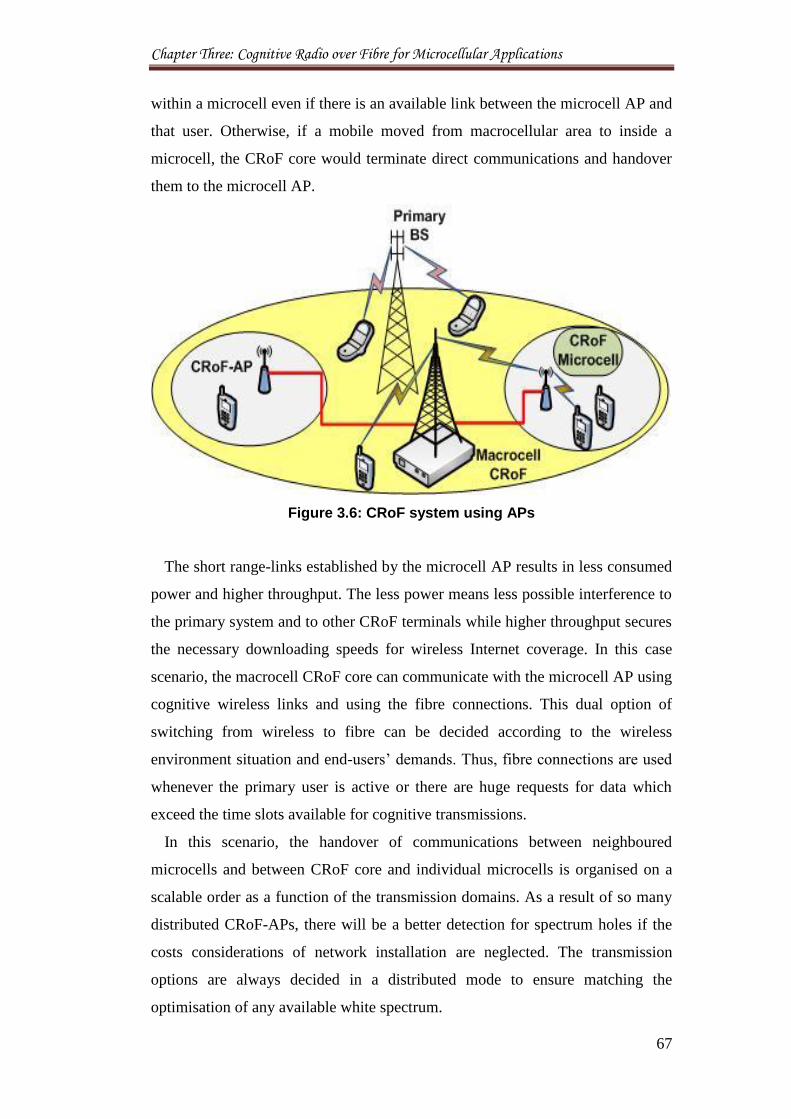
Chapter Three: Cognitive Radio over Fibre for Microcellular Applications
67
within a microcell even if there is an available link between the microcell AP and
that user. Otherwise, if a mobile moved from macrocellular area to inside a
microcell, the CRoF core would terminate direct communications and handover
them to the microcell AP.
Figure 3.6: CRoF system using APs
The short range-links established by the microcell AP results in less consumed
power and higher throughput. The less power means less possible interference to
the primary system and to other CRoF terminals while higher throughput secures
the necessary downloading speeds for wireless Internet coverage. In this case
scenario, the macrocell CRoF core can communicate with the microcell AP using
cognitive wireless links and using the fibre connections. This dual option of
switching from wireless to fibre can be decided according to the wireless
environment situation and end-users’ demands. Thus, fibre connections are used
whenever the primary user is active or there are huge requests for data which
exceed the time slots available for cognitive transmissions.
In this scenario, the handover of communications between neighboured
microcells and between CRoF core and individual microcells is organised on a
scalable order as a function of the transmission domains. As a result of so many
distributed CRoF-APs, there will be a better detection for spectrum holes if the
costs considerations of network installation are neglected. The transmission
options are always decided in a distributed mode to ensure matching the
optimisation of any available white spectrum.
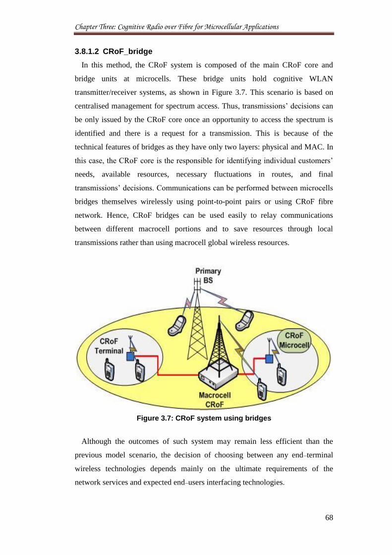
Chapter Three: Cognitive Radio over Fibre for Microcellular Applications
68
3.8.1.2 CRoF_bridge
In this method, the CRoF system is composed of the main CRoF core and
bridge units at microcells. These bridge units hold cognitive WLAN
transmitter/receiver systems, as shown in Figure 3.7. This scenario is based on
centralised management for spectrum access. Thus, transmissions’ decisions can
be only issued by the CRoF core once an opportunity to access the spectrum is
identified and there is a request for a transmission. This is because of the
technical features of bridges as they have only two layers: physical and MAC. In
this case, the CRoF core is the responsible for identifying individual customers’
needs, available resources, necessary fluctuations in routes, and final
transmissions’ decisions. Communications can be performed between microcells
bridges themselves wirelessly using point-to-point pairs or using CRoF fibre
network. Hence, CRoF bridges can be used easily to relay communications
between different macrocell portions and to save resources through local
transmissions rather than using macrocell global wireless resources.
Figure 3.7: CRoF system using bridges
Although the outcomes of such system may remain less efficient than the
previous model scenario, the decision of choosing between any end–terminal
wireless technologies depends mainly on the ultimate requirements of the
network services and expected end–users interfacing technologies.
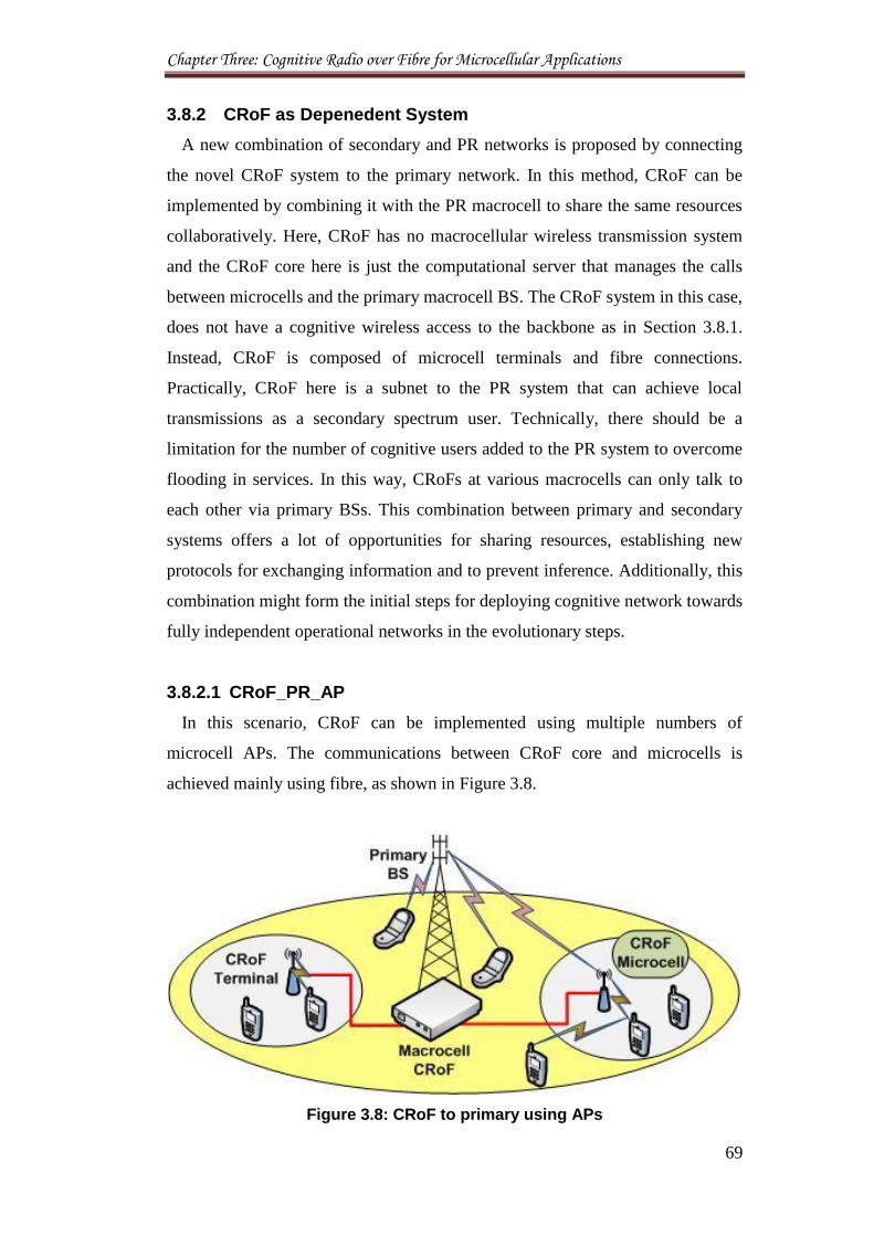
Chapter Three: Cognitive Radio over Fibre for Microcellular Applications
69
3.8.2 CRoF as Depenedent System
A new combination of secondary and PR networks is proposed by connecting
the novel CRoF system to the primary network. In this method, CRoF can be
implemented by combining it with the PR macrocell to share the same resources
collaboratively. Here, CRoF has no macrocellular wireless transmission system
and the CRoF core here is just the computational server that manages the calls
between microcells and the primary macrocell BS. The CRoF system in this case,
does not have a cognitive wireless access to the backbone as in Section 3.8.1.
Instead, CRoF is composed of microcell terminals and fibre connections.
Practically, CRoF here is a subnet to the PR system that can achieve local
transmissions as a secondary spectrum user. Technically, there should be a
limitation for the number of cognitive users added to the PR system to overcome
flooding in services. In this way, CRoFs at various macrocells can only talk to
each other via primary BSs. This combination between primary and secondary
systems offers a lot of opportunities for sharing resources, establishing new
protocols for exchanging information and to prevent inference. Additionally, this
combination might form the initial steps for deploying cognitive network towards
fully independent operational networks in the evolutionary steps.
3.8.2.1 CRoF_PR_AP
In this scenario, CRoF can be implemented using multiple numbers of
microcell APs. The communications between CRoF core and microcells is
achieved mainly using fibre, as shown in Figure 3.8.
Figure 3.8: CRoF to primary using APs
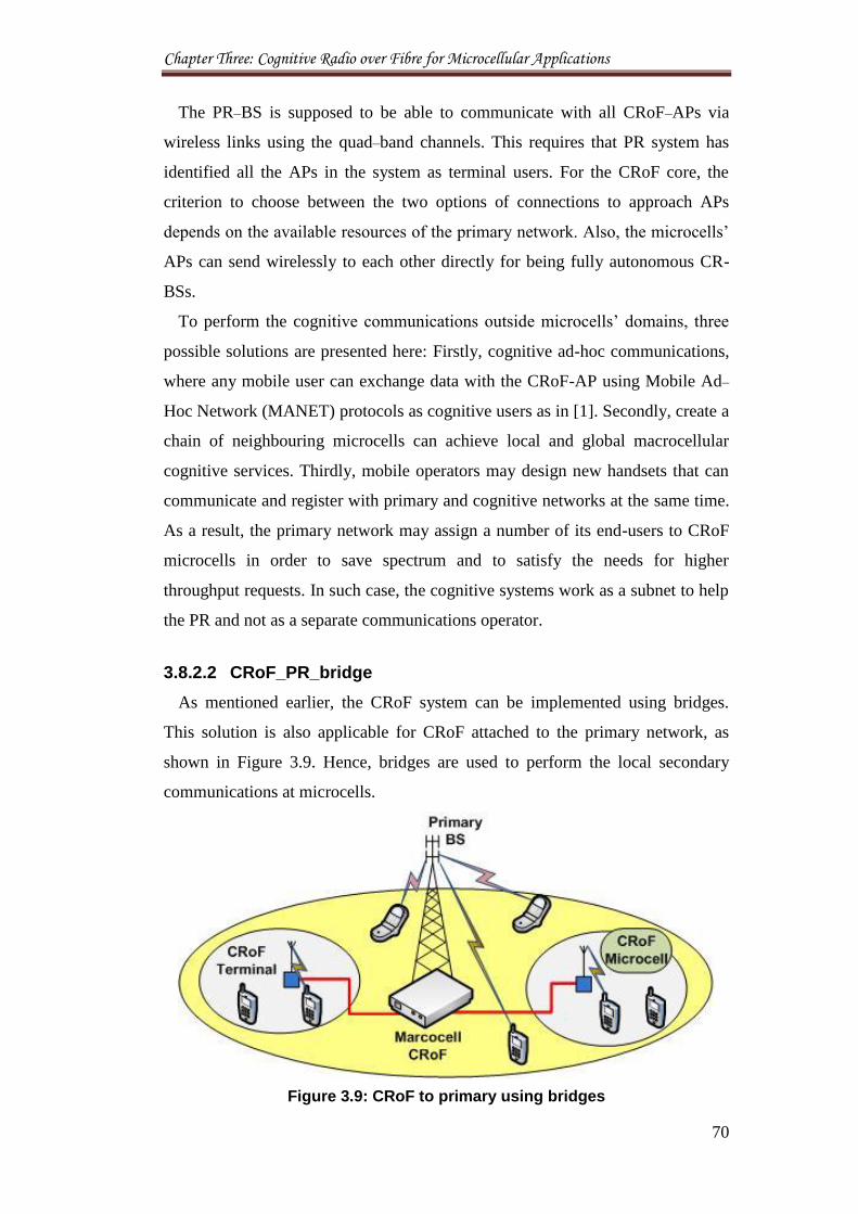
Chapter Three: Cognitive Radio over Fibre for Microcellular Applications
70
The PR–BS is supposed to be able to communicate with all CRoF–APs via
wireless links using the quad–band channels. This requires that PR system has
identified all the APs in the system as terminal users. For the CRoF core, the
criterion to choose between the two options of connections to approach APs
depends on the available resources of the primary network. Also, the microcells’
APs can send wirelessly to each other directly for being fully autonomous CR-
BSs.
To perform the cognitive communications outside microcells’ domains, three
possible solutions are presented here: Firstly, cognitive ad-hoc communications,
where any mobile user can exchange data with the CRoF-AP using Mobile Ad–
Hoc Network (MANET) protocols as cognitive users as in [1]. Secondly, create a
chain of neighbouring microcells can achieve local and global macrocellular
cognitive services. Thirdly, mobile operators may design new handsets that can
communicate and register with primary and cognitive networks at the same time.
As a result, the primary network may assign a number of its end-users to CRoF
microcells in order to save spectrum and to satisfy the needs for higher
throughput requests. In such case, the cognitive systems work as a subnet to help
the PR and not as a separate communications operator.
3.8.2.2 CRoF_PR_bridge
As mentioned earlier, the CRoF system can be implemented using bridges.
This solution is also applicable for CRoF attached to the primary network, as
shown in Figure 3.9. Hence, bridges are used to perform the local secondary
communications at microcells.
Figure 3.9: CRoF to primary using bridges
Chapter Three: Cognitive Radio over Fibre for Microcellular Applications
71
In this scenario, the CRoF can transmit to the microcells’ bridges using RoF
only. The reason for this is that bridges are not aware radios and not able to adapt
and receive the primary wireless transmissions as in CRoF-PR-AP scenario.
Therefore, the bridge will work as local secondary wireless terminals for a
landline CRoF system.
The combination of cognitive microcells to the primary networks seems to be a
promising step forwards in network systems managements. Additionally, this
hierarchical distribution of transmission domains allows mobile operators to
direct resources according to the data flow and end–users needs. However, the
success of this application is highly dependent on commercial aspects and
licensing issues between the primary operators and the future cognitive networks.
3.9 Network Modelling
In this section, the technologies used to create the coexistence models for the
simulation procedures are described briefly. The aim is to maximally utilise radio
resources of cognitive network in dynamic situations, offering mobile users an
improved data rates using different technologies of LTE at the macrocell
backbone and 802.11e at the microcells domains.
3.9.1 LTE Macrocell
The Release-10 LTE-Advanced (LTE-A) is a major enhancement of the Long
Term Evolution (LTE) standard developed by the 3rd Generation Partnership
Project (3GPP). LTE-A was ratified by the International Telecommunication
Union (ITU) as an IMT-Advanced (fourth generation, 4G) technology in
November 2010. The 4G objective is to meet challenges presented by the ever
increasing use of “smart” wireless devices that require significantly higher
spectral resources than conventional cell phones. LTE-A addresses those
challenges by targeting peak data rates up to 1 Gb/s with up to 100 MHz
supported spectrum bandwidth and by making use of high-order Multiple-Input
Multiple-Output (MIMO) transmission with up to eight spatial layers on the
downlink and four spatial layers on the uplink [23].
Proposals for CRoF aims at reduced delays, increased user data rates, increased
cell-edge bit-rate and seamless mobility with deployed marco Evolved Node B
Chapter Three: Cognitive Radio over Fibre for Microcellular Applications
72
(eNodeB) and micro WLAN. LTE-to-microcell networks enable local cell phone
coverage and provide access to high speed wireless broadband services, which
use smaller base station and existing fibre or other cable line as backhaul
connectivity. It can diverse the load from LTE macrocell networks as well as
reduce the operating and capital expenditure costs for operators.
LTE cell edge throughput maximisation is achieved mostly based on Link
Adaptation optimisation and dense frequency planning strategies. The other
solution is a smaller cell domain such as edge-microcellular system. These
microcells come in a variety of sizes and flavours depending on how much traffic
you want them to carry at a specific location. Classically WiFi hotspots are also
small cells and WiFi offload is likely to form part of a mobile operator’s strategy
in coping with network capacity demand. If traffic can be shifted onto WiFi,
normally terminated onto a fixed line broadband connection it takes the strain off
the mobile network.
3.9.2 IEEE802.11e for Microcell Cognitive Users
The 802.11b model is based on the application of the Carrier Sense Multiple
Access/Collision Avoidance (CSMA/CA) scheme known as the Distributed
Coordination Function (DCF). The DCF is using a timing technique linking the
Inter-Frame Space (IFS) and exponential backoff to avoid collisions and
guarantee equal throughput to all stations. In this way, a station must first listen
to the surrounding wireless environment before transmitting, or sense, the
wireless medium to determine if it is busy. If the DCF Inter-Frame Space (DIFS)
indicates an idle space then the station may transmit immediately. Otherwise, the
station enters a contention period in which it will utilise the exponential backoff
mechanism. The station selects a random backoff value from within the
Contention Window (CW) and continues to monitor the state of the medium.
When the medium remains free for a DIFS, the station starts to decrement its
backoff timer once for each time slot the medium is free. Once the backoff timer
reaches zero, the station will transmit. Otherwise, the station will freeze the timer
at its current value and resume countdown when the medium has been free for a
DIFS again.
The 802.11e is based on the original access mechanisms for 802.11b but has
added functionality for QoS guarantees in which data transmissions that contain
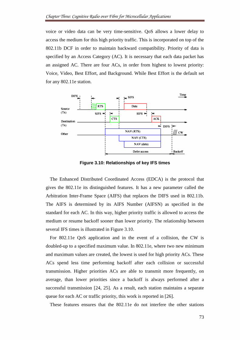
Chapter Three: Cognitive Radio over Fibre for Microcellular Applications
73
voice or video data can be very time-sensitive. QoS allows a lower delay to
access the medium for this high priority traffic. This is incorporated on top of the
802.11b DCF in order to maintain backward compatibility. Priority of data is
specified by an Access Category (AC). It is necessary that each data packet has
an assigned AC. There are four ACs, in order from highest to lowest priority:
Voice, Video, Best Effort, and Background. While Best Effort is the default set
for any 802.11e station.
Figure 3.10: Relationships of key IFS times
The Enhanced Distributed Coordinated Access (EDCA) is the protocol that
gives the 802.11e its distinguished features. It has a new parameter called the
Arbitration Inter-Frame Space (AIFS) that replaces the DIFS used in 802.11b.
The AIFS is determined by its AIFS Number (AIFSN) as specified in the
standard for each AC. In this way, higher priority traffic is allowed to access the
medium or resume backoff sooner than lower priority. The relationship between
several IFS times is illustrated in Figure 3.10.
For 802.11e QoS application and in the event of a collision, the CW is
doubled-up to a specified maximum value. In 802.11e, where two new minimum
and maximum values are created, the lowest is used for high priority ACs. These
ACs spend less time performing backoff after each collision or successful
transmission. Higher priorities ACs are able to transmit more frequently, on
average, than lower priorities since a backoff is always performed after a
successful transmission [24, 25]. As a result, each station maintains a separate
queue for each AC or traffic priority, this work is reported in [26].
These features ensures that the 802.11e do not interfere the other stations
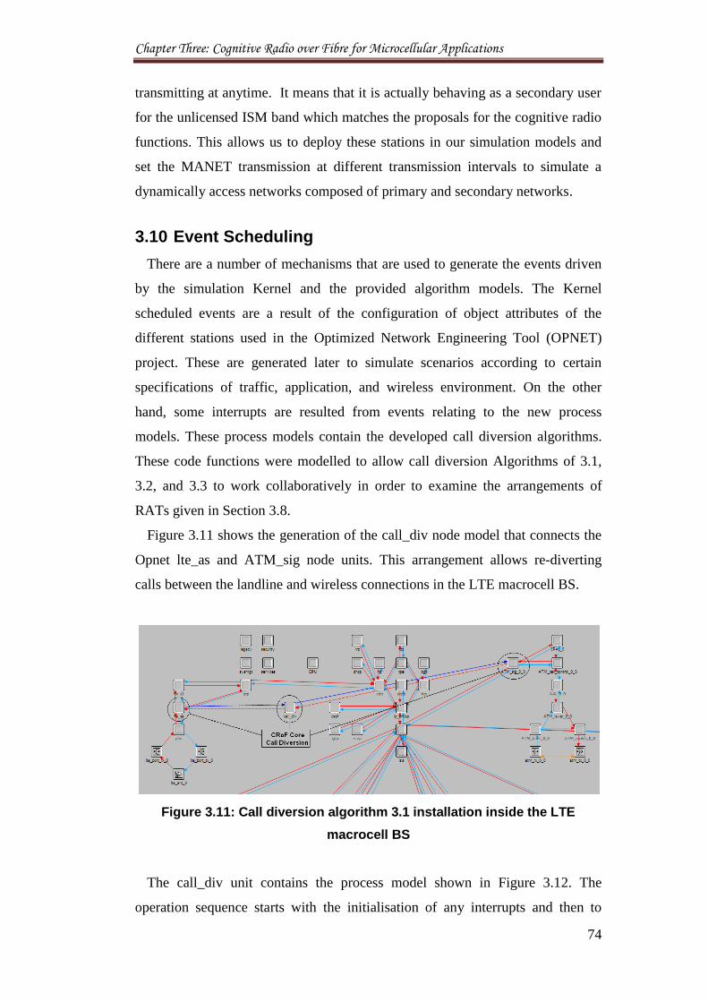
Chapter Three: Cognitive Radio over Fibre for Microcellular Applications
74
transmitting at anytime. It means that it is actually behaving as a secondary user
for the unlicensed ISM band which matches the proposals for the cognitive radio
functions. This allows us to deploy these stations in our simulation models and
set the MANET transmission at different transmission intervals to simulate a
dynamically access networks composed of primary and secondary networks.
3.10 Event Scheduling
There are a number of mechanisms that are used to generate the events driven
by the simulation Kernel and the provided algorithm models. The Kernel
scheduled events are a result of the configuration of object attributes of the
different stations used in the Optimized Network Engineering Tool (OPNET)
project. These are generated later to simulate scenarios according to certain
specifications of traffic, application, and wireless environment. On the other
hand, some interrupts are resulted from events relating to the new process
models. These process models contain the developed call diversion algorithms.
These code functions were modelled to allow call diversion Algorithms of 3.1,
3.2, and 3.3 to work collaboratively in order to examine the arrangements of
RATs given in Section 3.8.
Figure 3.11 shows the generation of the call_div node model that connects the
Opnet lte_as and ATM_sig node units. This arrangement allows re-diverting
calls between the landline and wireless connections in the LTE macrocell BS.
Figure 3.11: Call diversion algorithm 3.1 installation inside the LTE
macrocell BS
The call_div unit contains the process model shown in Figure 3.12. The
operation sequence starts with the initialisation of any interrupts and then to
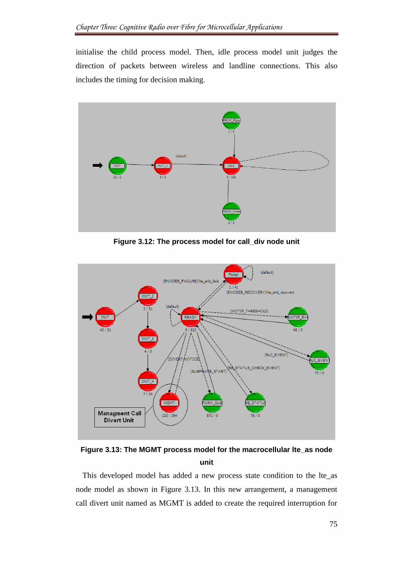
Chapter Three: Cognitive Radio over Fibre for Microcellular Applications
75
initialise the child process model. Then, idle process model unit judges the
direction of packets between wireless and landline connections. This also
includes the timing for decision making.
Figure 3.12: The process model for call_div node unit
Figure 3.13: The MGMT process model for the macrocellular lte_as node
unit
This developed model has added a new process state condition to the lte_as
node model as shown in Figure 3.13. In this new arrangement, a management
call divert unit named as MGMT is added to create the required interruption for
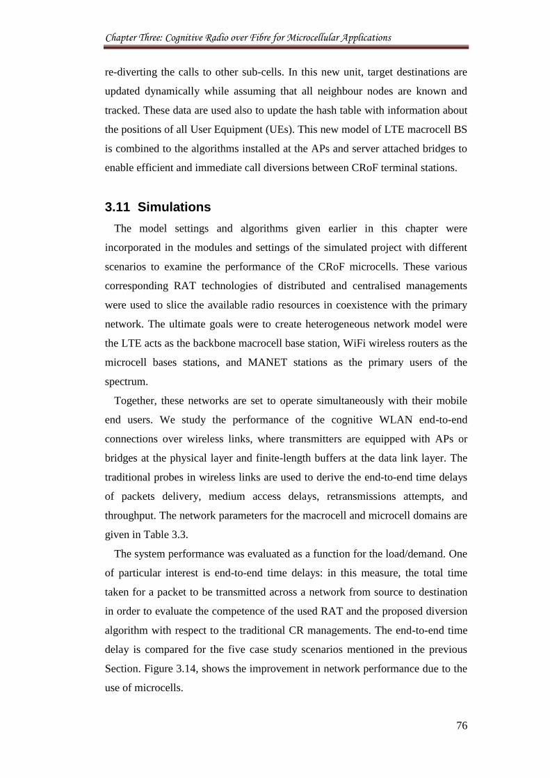
Chapter Three: Cognitive Radio over Fibre for Microcellular Applications
76
re-diverting the calls to other sub-cells. In this new unit, target destinations are
updated dynamically while assuming that all neighbour nodes are known and
tracked. These data are used also to update the hash table with information about
the positions of all User Equipment (UEs). This new model of LTE macrocell BS
is combined to the algorithms installed at the APs and server attached bridges to
enable efficient and immediate call diversions between CRoF terminal stations.
3.11 Simulations
The model settings and algorithms given earlier in this chapter were
incorporated in the modules and settings of the simulated project with different
scenarios to examine the performance of the CRoF microcells. These various
corresponding RAT technologies of distributed and centralised managements
were used to slice the available radio resources in coexistence with the primary
network. The ultimate goals were to create heterogeneous network model were
the LTE acts as the backbone macrocell base station, WiFi wireless routers as the
microcell bases stations, and MANET stations as the primary users of the
spectrum.
Together, these networks are set to operate simultaneously with their mobile
end users. We study the performance of the cognitive WLAN end-to-end
connections over wireless links, where transmitters are equipped with APs or
bridges at the physical layer and finite-length buffers at the data link layer. The
traditional probes in wireless links are used to derive the end-to-end time delays
of packets delivery, medium access delays, retransmissions attempts, and
throughput. The network parameters for the macrocell and microcell domains are
given in Table 3.3.
The system performance was evaluated as a function for the load/demand. One
of particular interest is end-to-end time delays: in this measure, the total time
taken for a packet to be transmitted across a network from source to destination
in order to evaluate the competence of the used RAT and the proposed diversion
algorithm with respect to the traditional CR managements. The end-to-end time
delay is compared for the five case study scenarios mentioned in the previous
Section. Figure 3.14, shows the improvement in network performance due to the
use of microcells.
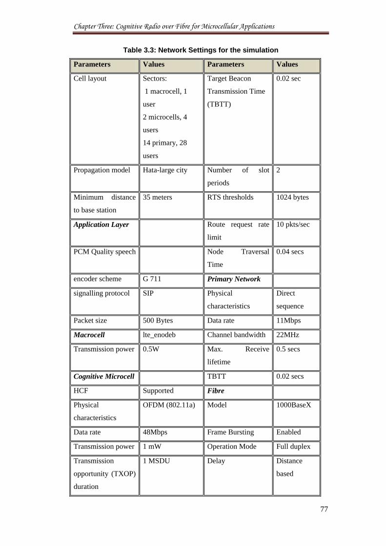
Chapter Three: Cognitive Radio over Fibre for Microcellular Applications
77
Table 3.3: Network Settings for the simulation
Parameters Values Parameters Values
Cell layout Sectors:
1 macrocell, 1
user
2 microcells, 4
users
14 primary, 28
users
Target Beacon
Transmission Time
(TBTT)
0.02 sec
Propagation model Hata-large city Number of slot
periods
2
Minimum distance
to base station
35 meters RTS thresholds 1024 bytes
Application Layer Route request rate
limit
10 pkts/sec
PCM Quality speech Node Traversal
Time
0.04 secs
encoder scheme G 711 Primary Network
signalling protocol SIP Physical
characteristics
Direct
sequence
Packet size 500 Bytes Data rate 11Mbps
Macrocell lte_enodeb Channel bandwidth 22MHz
Transmission power 0.5W Max. Receive
lifetime
0.5 secs
Cognitive Microcell TBTT 0.02 secs
HCF Supported Fibre
Physical
characteristics
OFDM (802.11a) Model 1000BaseX
Data rate 48Mbps Frame Bursting Enabled
Transmission power 1 mW Operation Mode Full duplex
Transmission
opportunity (TXOP)
duration
1 MSDU Delay Distance
based
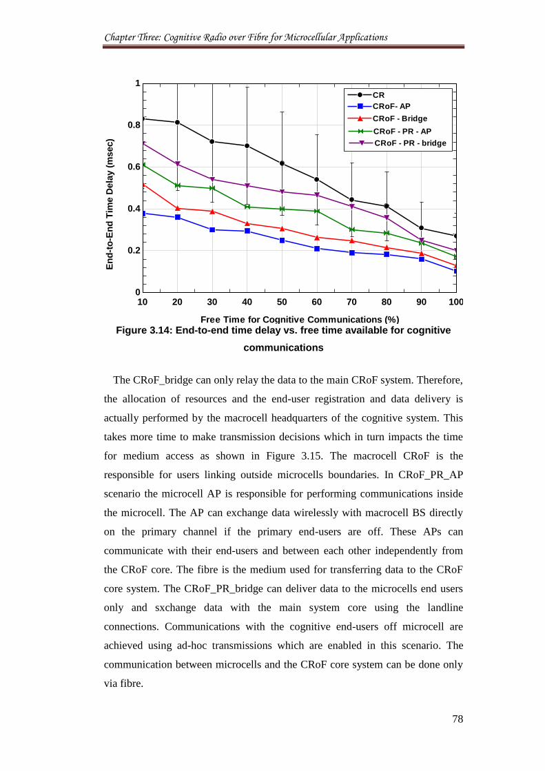
Chapter Three: Cognitive Radio over Fibre for Microcellular Applications
78
Figure 3.14: End-to-end time delay vs. free time available for cognitive
communications
The CRoF_bridge can only relay the data to the main CRoF system. Therefore,
the allocation of resources and the end-user registration and data delivery is
actually performed by the macrocell headquarters of the cognitive system. This
takes more time to make transmission decisions which in turn impacts the time
for medium access as shown in Figure 3.15. The macrocell CRoF is the
responsible for users linking outside microcells boundaries. In CRoF_PR_AP
scenario the microcell AP is responsible for performing communications inside
the microcell. The AP can exchange data wirelessly with macrocell BS directly
on the primary channel if the primary end-users are off. These APs can
communicate with their end-users and between each other independently from
the CRoF core. The fibre is the medium used for transferring data to the CRoF
core system. The CRoF_PR_bridge can deliver data to the microcells end users
only and sxchange data with the main system core using the landline
connections. Communications with the cognitive end-users off microcell are
achieved using ad-hoc transmissions which are enabled in this scenario. The
communication between microcells and the CRoF core system can be done only
via fibre.
10 20 30 40 50 60 70 80 90 1000
0.2
0.4
0.6
0.8
1
Free Time for Cognitive Communications (%)
En
d-t
o-E
nd
Tim
e D
ela
y (
msec)
CRoF- APCRoF- AP
CRCR
CRoF - BridgeCRoF - Bridge
CRoF - PR - APCRoF - PR - AP
CRoF - PR - bridgeCRoF - PR - bridge
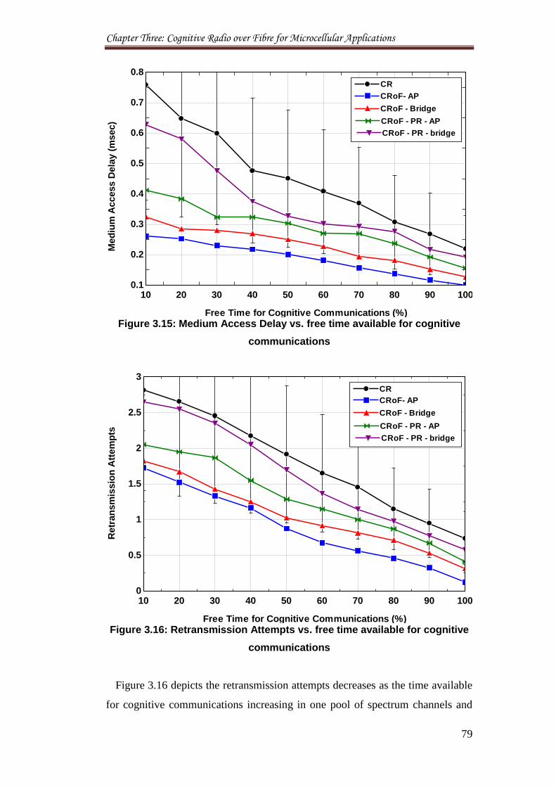
Chapter Three: Cognitive Radio over Fibre for Microcellular Applications
79
Figure 3.15: Medium Access Delay vs. free time available for cognitive
communications
Figure 3.16: Retransmission Attempts vs. free time available for cognitive
communications
Figure 3.16 depicts the retransmission attempts decreases as the time available
for cognitive communications increasing in one pool of spectrum channels and
10 20 30 40 50 60 70 80 90 1000.1
0.2
0.3
0.4
0.5
0.6
0.7
0.8
Med
ium
Access D
ela
y (
msec)
CRoF- APCRoF- AP
CRCR
CRoF - BridgeCRoF - Bridge
CRoF - PR - APCRoF - PR - AP
CRoF - PR - bridgeCRoF - PR - bridge
Free Time for Cognitive Communications (%)
10 20 30 40 50 60 70 80 90 1000
0.5
1
1.5
2
2.5
3
Retr
an
sm
issio
n A
ttem
pts
CRoF- APCRoF- AP
CRCR
CRoF - BridgeCRoF - Bridge
CRoF - PR - APCRoF - PR - AP
CRoF - PR - bridgeCRoF - PR - bridge
Free Time for Cognitive Communications (%)
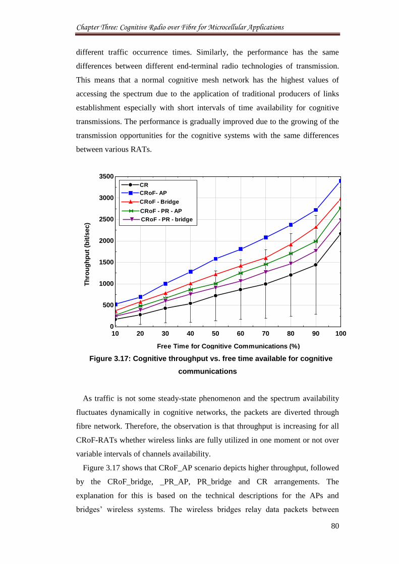
Chapter Three: Cognitive Radio over Fibre for Microcellular Applications
80
different traffic occurrence times. Similarly, the performance has the same
differences between different end-terminal radio technologies of transmission.
This means that a normal cognitive mesh network has the highest values of
accessing the spectrum due to the application of traditional producers of links
establishment especially with short intervals of time availability for cognitive
transmissions. The performance is gradually improved due to the growing of the
transmission opportunities for the cognitive systems with the same differences
between various RATs.
Figure 3.17: Cognitive throughput vs. free time available for cognitive
communications
As traffic is not some steady-state phenomenon and the spectrum availability
fluctuates dynamically in cognitive networks, the packets are diverted through
fibre network. Therefore, the observation is that throughput is increasing for all
CRoF-RATs whether wireless links are fully utilized in one moment or not over
variable intervals of channels availability.
Figure 3.17 shows that CRoF_AP scenario depicts higher throughput, followed
by the CRoF_bridge, _PR_AP, PR_bridge and CR arrangements. The
explanation for this is based on the technical descriptions for the APs and
bridges’ wireless systems. The wireless bridges relay data packets between
10 20 30 40 50 60 70 80 90 1000
500
1000
1500
2000
2500
3000
3500
Th
rou
gh
pu
t (b
it/s
ec)
CRoF- APCRoF- AP
CRCR
CRoF - BridgeCRoF - Bridge
CRoF - PR - APCRoF - PR - AP
CRoF - PR - bridgeCRoF - PR - bridge
Free Time for Cognitive Communications (%)
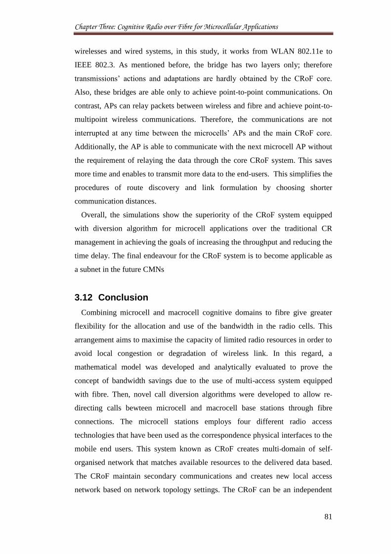
Chapter Three: Cognitive Radio over Fibre for Microcellular Applications
81
wirelesses and wired systems, in this study, it works from WLAN 802.11e to
IEEE 802.3. As mentioned before, the bridge has two layers only; therefore
transmissions’ actions and adaptations are hardly obtained by the CRoF core.
Also, these bridges are able only to achieve point-to-point communications. On
contrast, APs can relay packets between wireless and fibre and achieve point-to-
multipoint wireless communications. Therefore, the communications are not
interrupted at any time between the microcells’ APs and the main CRoF core.
Additionally, the AP is able to communicate with the next microcell AP without
the requirement of relaying the data through the core CRoF system. This saves
more time and enables to transmit more data to the end-users. This simplifies the
procedures of route discovery and link formulation by choosing shorter
communication distances.
Overall, the simulations show the superiority of the CRoF system equipped
with diversion algorithm for microcell applications over the traditional CR
management in achieving the goals of increasing the throughput and reducing the
time delay. The final endeavour for the CRoF system is to become applicable as
a subnet in the future CMNs
3.12 Conclusion
Combining microcell and macrocell cognitive domains to fibre give greater
flexibility for the allocation and use of the bandwidth in the radio cells. This
arrangement aims to maximise the capacity of limited radio resources in order to
avoid local congestion or degradation of wireless link. In this regard, a
mathematical model was developed and analytically evaluated to prove the
concept of bandwidth savings due to the use of multi-access system equipped
with fibre. Then, novel call diversion algorithms were developed to allow re-
directing calls bewteen microcell and macrocell base stations through fibre
connections. The microcell stations employs four different radio access
technologies that have been used as the correspondence physical interfaces to the
mobile end users. This system known as CRoF creates multi-domain of self-
organised network that matches available resources to the delivered data based.
The CRoF maintain secondary communications and creates new local access
network based on network topology settings. The CRoF can be an independent
Chapter Three: Cognitive Radio over Fibre for Microcellular Applications
82
secondary system or connected to the primary network. OPNET simulations
were conducted to examine the performance of the anticipated CRoF
management scenarios in comparison to the traditional CR system. Results show
that a CRoF system employing the diversion algorithm supported by APs at
microcells has improved performance compared to other microcells’
technologies and no CRoF cases.
3.13 References
[1] I. F. Akyildiz, W.-Y. Lee, and K. R. Chowdhury, “Spectrum Management
in Cognitive Radio Ad Hoc Networks,” IEEE Network, vol. 23, no. 4, 2009,
pp. 6 - 12.
[2] M. Sherman, A. N. Mody, R. Martinez, and C. Rodriguez, “IEEE Standards
Supporting Cognitive Radio and Networks, Dynamic Spectrum Access, and
Coexistence,” IEEE Comms. Magazine, vol. 46, no. 7, 2008, pp. 72 - 79.
[3] R. Llorente, M. Morant, T. Tokle, T. Quinlan, M. Thakur, S. Walker,
“UWB Radio-over-Fiber and Photonic Sensing for Cognitive Optical
Access Networks,” In proceedings of the IEEE LEOS, 2009, pp. 733 - 734.
[4] FP7 project End-to-End Efficiency (E3): ‘Self-x in Radio Access
Networks’, E3 White Paper, Version 1.0, 2008.
[5] H. Li, Q. Pang, and V.C.M. Leung, “Cognitive Access Points for Dynamic
Radio Resource Management in Wireless LAN over Fiber,” In proceedings
of the Wireless World Research Forum WWRF#20 meeting, Ontario,
Canada, April 2008.
[6] H. Li, A. Attar, V.C.M. Leung, and Q. Pang, “Collusion Avoidance and
Mitigation in Cognitive Wireless Area Network over Fibre,” In proceedings
of the 1st International Conference on Evolving Internet, French Riviera,
France, 2009, pp. 133 - 138.
[7] A. Al-Dulaimi, H. S. Al-Raweshidy, J. Cosmas, and J. Loo, “Cognitive
Mesh Networks: Cognitive Radio over Fibre for Microcells Applications,”
IEEE Vehicular Technology Magazine, vol. 5, no. 3, 2010, pp. 54 - 60.
[8] J. Martyna, “A Mathematical Framework for the Multidimensional QoS in
Cognitive Radio Networks,” Smart Spaces and Next Generation
Chapter Three: Cognitive Radio over Fibre for Microcellular Applications
83
Wired/Wireless Networking Lecture Notes in Computer Science, vol.
6869/2011, 2011, pp. 440 - 449.
[9] M. Dohler, S. A. Ghorashi, M. Ghozzi, M. Arndt, F. Said , and A. H.
Aghvami, “Towards reconfigurable and cognitive communications:
Opportunistic scheduling using cognitive radio,” Comptes Rendus
Physique, vol. 7, no. 7, 2006, pp. 805 - 815.
[10] P. Zhou, Y. Chang, and J. A. Copeland, “Capacity and Delay Scaling in
Cognitive Radio Ad-Hoc Networks: Impact of Primary User Activity,” In
proceeding of the IEEE Globecom (2010), Florida, USA, 2010, pp. 1 - 6.
[11] C. Doerr, D. C. Sicker, and D. Grunwald, “Dynamic Control Channel
Assignment in Cognitive Radio Networks using Swarm Intelligence,” In
proceeding of the IEEE Globecom (2008), New Orleans, USA, 2008, pp. 1
- 6.
[12] M. Haenggi, J. G. Andrews, F. Baccelli, O. Dousse, and M. Franceschetti.
“Stochastic geometry and random graphs for the analysis and design of
wireless networks,” IEEE Journal on Sel. Areas on Comm., vol. 27, no. 7,
2009, pp. 1029 - 1046.
[13] J.F.C Kingman. Poisson Processes. Oxford University Press, 1993.
[14] A. Dasgupta and A. E. Raftery, “Detecting Features in Spatial Point
Processes with Clutter via Model-Based Clustering,” Journal of the
American Statistical Association, vol. 93, no. 441, 1998, pp. 294 - 302.
[15] T. A. Weiss and F. K. Jondral, “Spectrum pooling: An innovative strategy
for the enhancement of spectrum efficiency,” IEEE Communications
Magazine, vol. 42, no. 3, 2004, pp. S8 - S14.
[16] B. Farhang-Boroujeny and R. Kempter, “Multicarrier communication
techniques for spectrum sensing and communication in cognitive radios,”
IEEE Communications Magazine, vol. 46, no. 4, 2008, pp. 80 - 85.
[17] G. Bansal, Md. J. Hossain, and Vijay K. Bhargava, “Optimal and
Suboptimal Power Allocation Schemes for OFDM-based Cognitive Radio
Systems,” IEEE Transactions on Wireless Communications, vol. 7, no. 11,
2008, pp. 4710 - 4718.
[18] C. R. Stevenson, G. Chouinard, Z. Lei, W. Hu, S. J. Shellhammer, and W.
Caldwell, “IEEE 802.22: The First Cognitive Radio Wireless Regional
Chapter Three: Cognitive Radio over Fibre for Microcellular Applications
84
Area Network Standard,” IEEE Communications Magazine , vol. 47, no. 1,
2009, pp. 130 - 138.
[19] D. Niyato and E. Hossain, “Competitive pricing for spectrum sharing in
cognitive radio networks: Dynamic game, inefficiency of Nash equilibrium,
and collusion,” IEEE Journal of Selected Areas on Communications, vol.
26, no. 1, 2008, pp. 192 - 202.
[20] A. Goldsmith and S. G. Chua, “Variable-rate variable-power MQAM for
fading channels,” IEEE Trans. Communications, vol. 45, no. 10, 1997, pp.
1218 - 1230.
[21] H. S. Jo, Y. J. Sang, P. Xia, and J. G. Andrews, “Outage probability for
heterogeneous cellular networks with biased cell association,” In
proceedings of IEEE Globecom (2011), Texas, USA, 2011, pp. 1 - 5.
[22] H. S. Al-Raweshidy and S. Komaki, Radio over Fibre Technologies for
Mobile Communications Networks, Artech House, London, 2002, ISBN 1 -
58053 - 148 - 2.
[23] C. Zhang, S. Ariyavisitakul, and M. Tao, “LTE-Advanced and 4G Wireless
Communications,” IEEE Communications Magazine, vol. 50, no. 2, 2012,
pp. 102 - 103.
[24] D. J. Thuente, B. Newlin, and M. Acharya, “Jamming vulnerabilities of
IEEE 802.11e,” in Proceedings of the 26th IEEE Communications Society
Military Communications Conference (MILCOM), Florida, USA, 2007, pp.
1 - 7.
[25] IEEE Std. 802.11e-2005 Wireless LAN Medium Access Control Quality of
Service Enhancements, 2005.
[26] S. Al-Rubaye, A. Al-Dulaimi, and J. Cosmas, “Cognitive Femtocell: Future
Wireless Networks for Indoor Applications,” IEEE Vehicular Technology
Magazine, vol. 6, no. 1, 2011, pp. 44 - 51.
Chapter Four: Optimising Cell Size and Power Consumption for LTE Networks
85
Chapter 4
Optimising Cell Size and Power
Consumption for LTE Networks
Optimised roadmap for the possible numbers of deployed microcells is
proposed for cognitive networks. The studied system incorporates two tiers of
cognitive coverage as macrocell and microcell domains with various local
spectrum coexistence scenarios. The limitations of the free spectrum and the
competition in accessing and sharing resources among secondary users are the
main concerns while deploying cognitive microcells. This chapter proposes and
analyses novel coexistence models for sharing the spectrum between cognitive
microcells inside one typical LTE macrocell. The given algorithms and network
architectural models solutions are validated by analysing the upload capacity for
various numbers of microcells. Results show the dependence of the microcells’
density on the number of free available channels, and that services start to
decline at certain thresholds when microcells overlapping with each other in
coverage areas and used channels. The models of study were further investigated
using designed simulations to analyse the power consumption for the new two-
tier cognitive heterogeneous networks. Results show that microcells can reduce
the power consumed in comparison with the traditional macrocellular services
models. A novel road map for deploying cognitive microcells with the optimum
secondary users’ density in coexistence with the primary networks is raised to the
research and industry communities.
Chapter Four: Optimising Cell Size and Power Consumption for LTE Networks
86
4.1 Motivation
The rapid adoption of mobile data services triggered by the availability of
dongles, smartphones, and tablets is placing heavy traffic demands on cellular
networks and making them congested. In order to supply these demands,
operators will need to increase capacity with the three key ingredients of a
wireless network: spectrum, spectral efficiency (a property of the technology)
and cell density. Combining these three factors gives us capacity density,
measured in (Mbps per km2). Therefore, mobile operators will need to deploy
dense networks of low-power small cells located near to users, in order to supply
sufficient capacity density high-quality contiguous/ubiquitous coverage in order
to meet the ever growing demands for mobile broadband services [1]. Long Term
Evolution-Advanced (LTE-A) wireless networks are being designed to improve
spectral efficiency per unit area by shrinking cell size via deployment of a
diverse set of base-stations [2]. However, a heterogeneous network that
integrates the optical and wireless systems into one access system is still the best
solution for the evolution of a diverse mobile coexistence in future networks. The
Cognitive Radio over Fibre is one of these solutions proposed for the future
secondary networks [3 - 5].
The shorter transmission distance coupled with lower transmitted power that
can be obtained through microcells, enhances both capacity as well as the SNR
values that can be achieved within the macrocell. On the other hand, a designer
or a system architect would have to answer questions such as: What is the
optimum number of sub-cells that could be contained in a macrocell? What is the
optimum cell size that maximises the throughput obtained due to the sub-cells
installation? Does the receiver configuration matter? What is the implication of
frequency reuse on the throughput achievable? [6].
The other question that can be raised here is how to make the cellular networks
more power efficient in order to sustain high speed data-traffic is by decreasing
the propagation distance between nodes, which leads to reduce the transmitted
power. Cell partition and the deployment solutions based on smaller cells such as
micro, pico and femtocells are very promising in this context. A typical microcell
in a mobile phone network is served by a low power cellular BS that covers a
small area with dense traffic such as a shopping mall, residential areas, a hotel, or
Chapter Four: Optimising Cell Size and Power Consumption for LTE Networks
87
a train station in the order of few hundred metres [7, 8]. As, the use of cognitive
over fibre microcells to support cognitive mesh networks is a very new idea,
therefore, none of the literature quantitatively addresses the impact of increasing
the number of cognitive microcells on the practical capacity of the secondary
multiple-access cognitive network and the quality of the proposed services. This
chapter investigates the collision in services due to over the limits density of
equipment. Along this line, this chapter characterises the optimal CRoF
microcells network architecture by addressing the following questions:
What is the optimal number of CRoF microcells that can be installed
inside an LTE macrocell?
How to arrange the spectrum coexistence of the newly installed cognitive
microcells with primary users transmitting in the same existing band
channels?
What are the power implications of adding various numbers of microcells
to LTE macrocells?
To answer these questions, CRoF microcells’ coexistence was investigated
using two different new approaches named: Space Filling and Time Filling.
Firstly, the space is filled with cognitive microcells that are able to control and
adapt their coverage areas from inter-lapping with each other. Practically, a
cognitive macrocell is the home for cognitive microcells with different levels of
awareness and independence, where any channel can be used by different non-
adjacent microcells using the frequency reuse principles. Secondly, the
microcells are installed randomly throughout the macrocell, where their coverage
areas can overlap, and spectrum is used by all microcells as one common pool. In
this regard, a novel scheduling for spectrum access is used as an approach for
coexistence between many primary and secondary users along the same channels
of the IEEE 802.11e. This allows the modelling of the spectrum access for the
newly installed microcells as a Poisson Process. In this scenario, microcells
access the holes in the spectrum based on the first come first served principle in
their spatial locations. The main goal is to optimise the cell size design for the
next generation networks.
Chapter Four: Optimising Cell Size and Power Consumption for LTE Networks
88
4.2 Technical Contributions
By characterising the various CRoF techniques for microcells deployment, this
chapter makes the following main contributions:
1. Investigating the coexistence of a cognitive microcell network for different
CRoF architectural designs in coexistence with primary users for all used
channels, jointly, considering the optimal number of microcells installed,
and macrocell design policy for planning future cognitive mesh networks.
2. The most recent information-theoretic results on the IEEE 802.11af
coexistence management are incorporated into this chapter to investigate
the capacity of cognitive systems with adaptively sized microcells’
coverage areas [9 - 12]. The analytical approach employed the probability
that an end-user suddenly left off-connection due to the changes in
microcells’ transmission domains.
3. Comprehensive study of the different microcellular RATs, in order to
further investigate the CRoF architecture proposed in [13]. This helps to set
the fibre network installation requirements and to regulate coexistence
between the future cognitive mesh networks and the primary networks.
4. Power optimisation of the macro-to-micro cellular system using a
developed model for the LTE macro base station with realistic factors for
heterogeneous cell deployments.
4.3 Dimensioning of Cognitive Networks
Mobile capacity is determined not by one single factor, but by three: the
amount of spectrum; the efficiency of the technology; and the number of cells
deployed. Unlike spectrum and technology, the number of cells is limited only by
the economics of deploying more. Over the last few decades most of the gains in
capacity have come from more cell sites. The likelihood that mobile operators
would have the inclination and the resources to increase their network ten-fold,
from around 15,000 cells in the UK to around 150,000, is remote. If the will
exists on the part of mobile operators and other initiative leaders, however, there
are alternative strategies that, arguably, could take advantage of an existing
wireless infrastructure; one that would also make the most of the opportunities
Chapter Four: Optimising Cell Size and Power Consumption for LTE Networks
89
that access convergence can offer [14].
The main goals behind the development of the CRoF system are to utilise
resources locally to attain more transmission opportunities for the secondary
network. To do this, microcells are installed for small wireless enterprise objects.
The main assumption in this proposal is that microcells’ fibre connections can be
provided through the accessible fibre connections, for instance the EU-Project
FUTON which is designed for the 4G networks. This work is concentrated at the
management of the hybrid optical-radio infrastructure existing between the fibre
optic interface of the central unit and the RAUs architecture. [15]. Hence, there
are no worries regarding the cost and availably of landline connections for the
anticipated CRoF linking. The main outcomes of the cognitive microcells
deployment are:
Efficient access to short time holes in the spectrum on spatial basis. This
helps in overcoming the spectrum unavailability problem through
adaptive directed coverage beams of the cognitive microcells’ stations.
Obviously, more opportunities can be obtained for transmission with such
an application [13].
Increasing the overall throughput of the system through short and reliable
communications. This means that less end-to-end time delays will occur
during packet delivery all over the network as a result of the microcells
and the landline applications. This reduces the complexity that the
cognitive network is facing in sharing the spectrum with other users.
Local coverage and access for the clients. This makes it much easier to
track the subscribers and the delivery of huge-sized data.
Lower cost of communications by saving power and spectrum leasing
time. This is an important factor to be studied in order to understand the
cost effectiveness of microcells’ installation against the traditional
macrocell costs of wireless broadcasting.
Higher performance and lower network duty cycle. This is very important
to achieve time-effective response to the dynamic changes of a cognitive
wireless environment. This is achieved in this proposal through
infrastructural modifications.
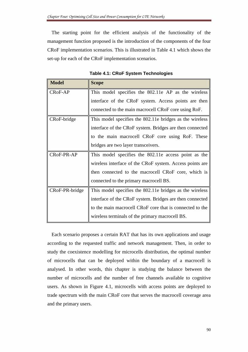
Chapter Four: Optimising Cell Size and Power Consumption for LTE Networks
90
The starting point for the efficient analysis of the functionality of the
management function proposed is the introduction of the components of the four
CRoF implementation scenarios. This is illustrated in Table 4.1 which shows the
set-up for each of the CRoF implementation scenarios.
Table 4.1: CRoF System Technologies
Model Scope
CRoF-AP This model specifies the 802.11e AP as the wireless
interface of the CRoF system. Access points are then
connected to the main macrocell CRoF core using RoF.
CRoF-bridge This model specifies the 802.11e bridges as the wireless
interface of the CRoF system. Bridges are then connected
to the main macrocell CRoF core using RoF. These
bridges are two layer transceivers.
CRoF-PR-AP This model specifies the 802.11e access point as the
wireless interface of the CRoF system. Access points are
then connected to the macrocell CRoF core, which is
connected to the primary macrocell BS.
CRoF-PR-bridge This model specifies the 802.11e bridges as the wireless
interface of the CRoF system. Bridges are then connected
to the main macrocell CRoF core that is connected to the
wireless terminals of the primary macrocell BS.
Each scenario proposes a certain RAT that has its own applications and usage
according to the requested traffic and network management. Then, in order to
study the coexistence modelling for microcells distribution, the optimal number
of microcells that can be deployed within the boundary of a macrocell is
analysed. In other words, this chapter is studying the balance between the
number of microcells and the number of free channels available to cognitive
users. As shown in Figure 4.1, microcells with access points are deployed to
trade spectrum with the main CRoF core that serves the macrocell coverage area
and the primary users.
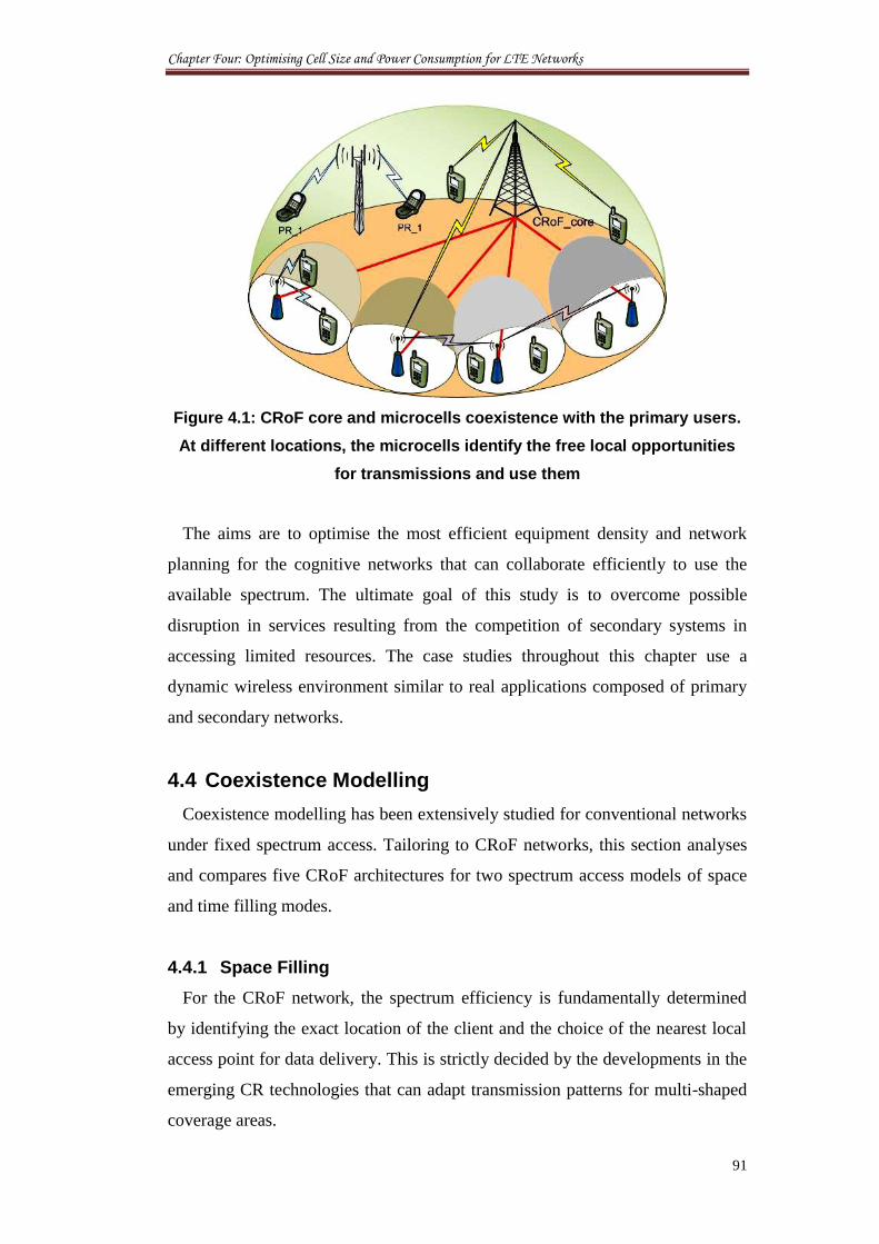
Chapter Four: Optimising Cell Size and Power Consumption for LTE Networks
91
Figure 4.1: CRoF core and microcells coexistence with the primary users.
At different locations, the microcells identify the free local opportunities
for transmissions and use them
The aims are to optimise the most efficient equipment density and network
planning for the cognitive networks that can collaborate efficiently to use the
available spectrum. The ultimate goal of this study is to overcome possible
disruption in services resulting from the competition of secondary systems in
accessing limited resources. The case studies throughout this chapter use a
dynamic wireless environment similar to real applications composed of primary
and secondary networks.
4.4 Coexistence Modelling
Coexistence modelling has been extensively studied for conventional networks
under fixed spectrum access. Tailoring to CRoF networks, this section analyses
and compares five CRoF architectures for two spectrum access models of space
and time filling modes.
4.4.1 Space Filling
For the CRoF network, the spectrum efficiency is fundamentally determined
by identifying the exact location of the client and the choice of the nearest local
access point for data delivery. This is strictly decided by the developments in the
emerging CR technologies that can adapt transmission patterns for multi-shaped
coverage areas.
Chapter Four: Optimising Cell Size and Power Consumption for LTE Networks
92
A novel IEEE standard for cognitive radio has been developed by several
groups at the end of 2009. However, the IEEE 802.11af working group has been
created to present several modifications to both the 802.11 PHY layer and the
802.11 MAC layers, to link the channel access requirements and coexistence in
the TV white spaces. In addition, the IEEE 802.19 group is working with regard
to developing standards for allowing the coexistence between wireless standards
for unlicensed devices [9 - 11]. It is expected that this work will build on IEEE
802.11y results, where an inherent key issue was addressed and resolved in a
different context; the Dependent Station Enablement (DSE) mechanism defines
how an operator extends and retracts permission for license exempt devices to
use licensed radio spectrum; IEEE 802.19, on the other hand, works towards
enabling the family of IEEE 802 Wireless Standards to most effectively use TV
White Space by providing standard coexistence methods. Furthermore, IEEE
SCC41 is developing standards related to dynamic spectrum access networks
with a focus on improved spectrum usage. In this framework, the IEEE standard
1900.4, 2009 defines a management system supporting network terminal
distributed optimisation of radio resource usage and improvement in QoS in
heterogeneous wireless networks. Several CR standards are currently under
development, mainly within the formworks of the IEEE and the European
Telecommunications Standards Institute (ETSI). One of the first IEEE Working
Groups (WG) to consider CR technology was IEEE 802.22, created in 2004, and
developing a standard for Wireless Regional Area Networks (WRAN) using
White Spaces in the TV frequency spectrum [12].
Therefore, it is assumed that there is always a chance to add more cognitive
microcells to a fixed sized macrocell, as shown in Figure 4.2. Two scenarios are
likely to occur:
1. Firstly, microcells do not overlap their coverage areas with each other.
Thus, microcells squeeze their transmissions’ areas whenever a new
microcell is positioned inside the macrocell. Obviously, such an adaption
affects mainly the neighbouring microcells for the newly installed
microcell unit. As a result, the macrocell may contain areas with different
microcells’ densities. To ensure reliable coexistence and non-interfering
sharing of the spectrum, the reuse frequency is vital for the success of this
Chapter Four: Optimising Cell Size and Power Consumption for LTE Networks
93
implementation scenario. In other words, when a microcell uses a certain
channel, its neighbouring microcells do not use the same channel for
transmission at the same time. The reason for this is that competition on
resources in a tiny coverage area may affect the rights of the primary user
and increase the risk of the hidden point. The major task here is the
management of the spectrum access in such a competitive, dynamic,
wireless environment. This can be solved in two steps, firstly, through
using the CRoF core entity to manage the channel sharing between the
CRoF microcells. Then, CSCC [16] can be used to negotiate channels’
sharing between neighbouring microcells in a distributed, localised
manner. In this way, the microcells can accommodate newly installed
microcells by adapting their coverage patterns and their used channels on a
dynamic basis. The microcells are supposed to use sensing in order to
perform the coexistence scenarios and have no advance knowledge of any
future microcells’ installations. Hence, accurate and efficient sensing is
crucial for the success of such a system. Secondly, the CRoF core may act
also as a spectrum broker to allocate the channels between the microcells in
the macrocell boundaries. This requires the registration of the microcell IP
with the CRoF core for any new installed microcell. The question what is
the time taken for issuing a request of spectrum access from a microcell to
the macrocell and the time of approving that request with respect to the
spectrum opportunity? will remain always here, especially if the time taken
for the CR to access and leave a certain channel opportunity does not
exceed a few tens of microseconds [17]. This situation motivates the
management of spectrum access even in an open access system like this
one. Also, this is essential for operators to decide services and charge end-
users for their spectrum usage.
2. In the second scenario for microcells installation, the microcells are
assumed to be overlapped in their coverage areas as one nest. Thus, there
will be shorter distances between microcells stations as shown in Figure
4.2. This makes the coexistence more challenging for service providers for
allocating their subscribers, and to decide which microcells should be
involved in performing transmissions and responding to the clients’
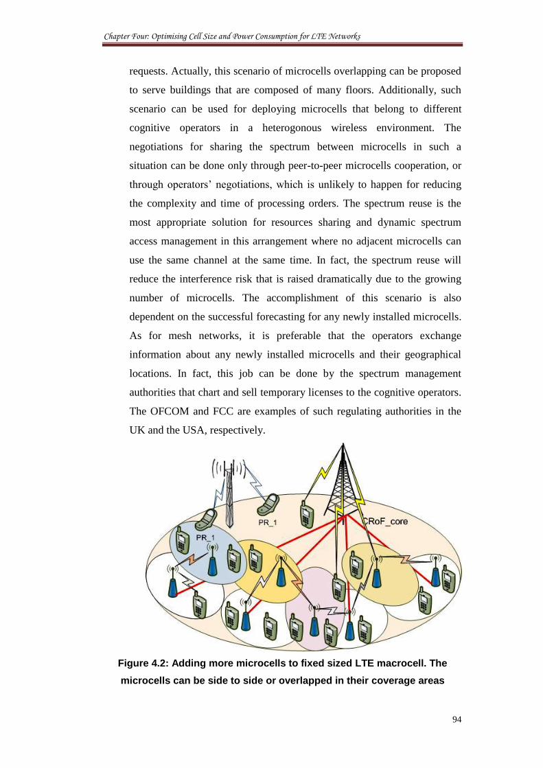
Chapter Four: Optimising Cell Size and Power Consumption for LTE Networks
94
requests. Actually, this scenario of microcells overlapping can be proposed
to serve buildings that are composed of many floors. Additionally, such
scenario can be used for deploying microcells that belong to different
cognitive operators in a heterogonous wireless environment. The
negotiations for sharing the spectrum between microcells in such a
situation can be done only through peer-to-peer microcells cooperation, or
through operators’ negotiations, which is unlikely to happen for reducing
the complexity and time of processing orders. The spectrum reuse is the
most appropriate solution for resources sharing and dynamic spectrum
access management in this arrangement where no adjacent microcells can
use the same channel at the same time. In fact, the spectrum reuse will
reduce the interference risk that is raised dramatically due to the growing
number of microcells. The accomplishment of this scenario is also
dependent on the successful forecasting for any newly installed microcells.
As for mesh networks, it is preferable that the operators exchange
information about any newly installed microcells and their geographical
locations. In fact, this job can be done by the spectrum management
authorities that chart and sell temporary licenses to the cognitive operators.
The OFCOM and FCC are examples of such regulating authorities in the
UK and the USA, respectively.
Figure 4.2: Adding more microcells to fixed sized LTE macrocell. The
microcells can be side to side or overlapped in their coverage areas
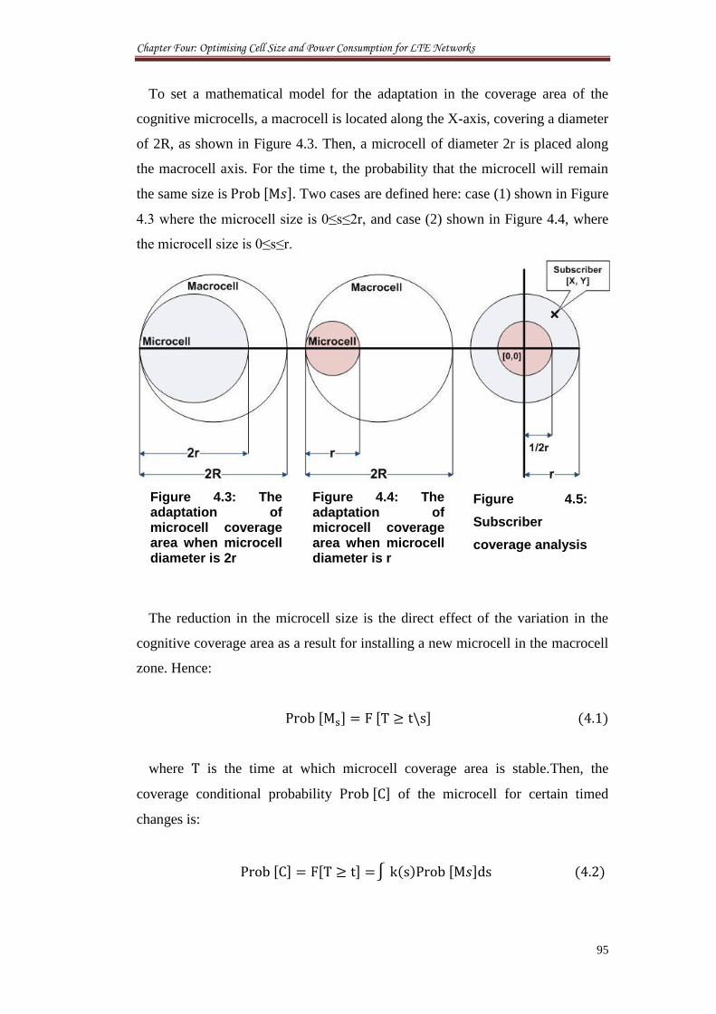
Chapter Four: Optimising Cell Size and Power Consumption for LTE Networks
95
To set a mathematical model for the adaptation in the coverage area of the
cognitive microcells, a macrocell is located along the X-axis, covering a diameter
of 2R, as shown in Figure 4.3. Then, a microcell of diameter 2r is placed along
the macrocell axis. For the time t, the probability that the microcell will remain
the same size is [ ]. Two cases are defined here: case (1) shown in Figure
4.3 where the microcell size is 0≤s≤2r, and case (2) shown in Figure 4.4, where
the microcell size is 0≤s≤r.
The reduction in the microcell size is the direct effect of the variation in the
cognitive coverage area as a result for installing a new microcell in the macrocell
zone. Hence:
[ ] [ ]
where is the time at which microcell coverage area is stable.Then, the
coverage conditional probability [ ] of the microcell for certain timed
changes is:
[ ] [ ] [ ]
Figure 4.3: The adaptation of microcell coverage area when microcell diameter is 2r
Figure 4.4: The adaptation of microcell coverage area when microcell diameter is r
Figure 4.5:
Subscriber
coverage analysis
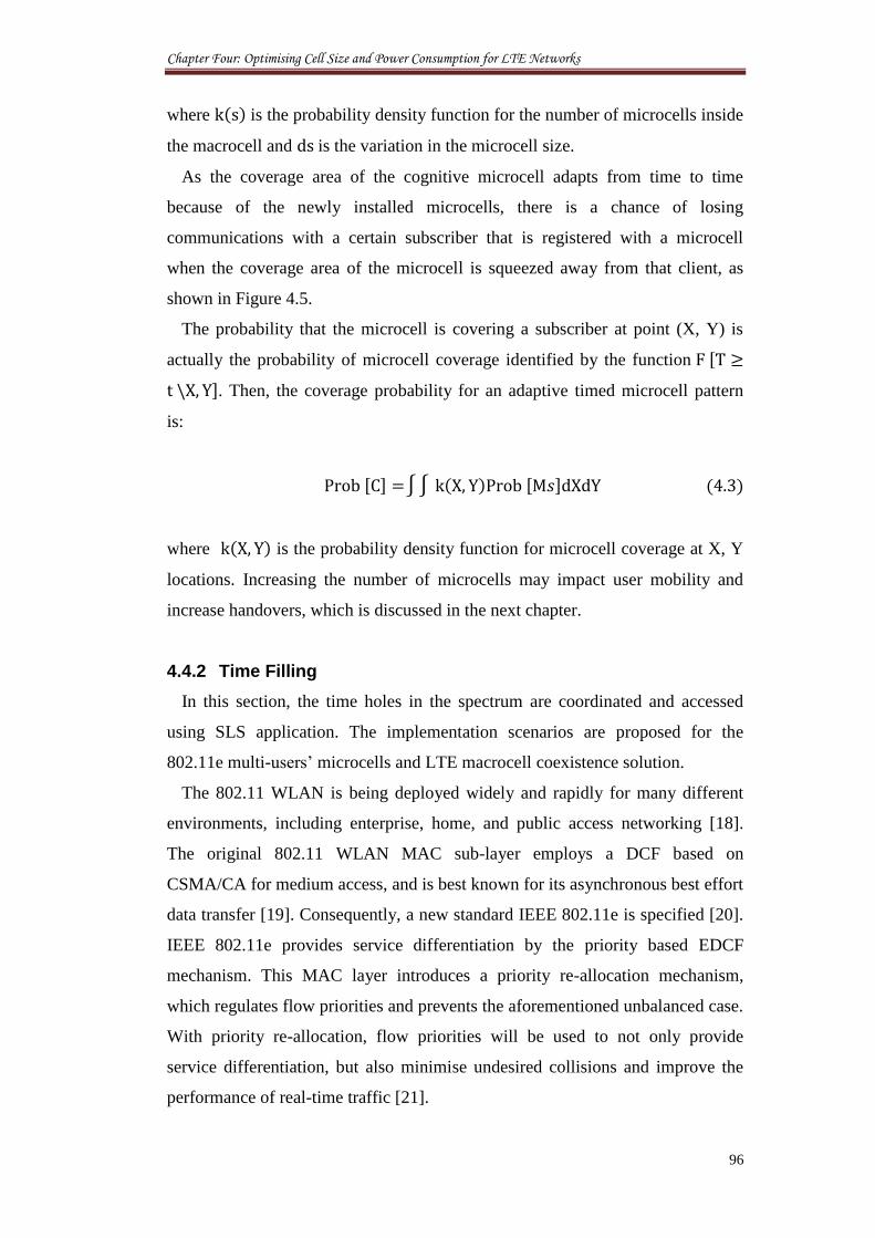
Chapter Four: Optimising Cell Size and Power Consumption for LTE Networks
96
where is the probability density function for the number of microcells inside
the macrocell and is the variation in the microcell size.
As the coverage area of the cognitive microcell adapts from time to time
because of the newly installed microcells, there is a chance of losing
communications with a certain subscriber that is registered with a microcell
when the coverage area of the microcell is squeezed away from that client, as
shown in Figure 4.5.
The probability that the microcell is covering a subscriber at point (X, Y) is
actually the probability of microcell coverage identified by the function [
]. Then, the coverage probability for an adaptive timed microcell pattern
is:
[ ] [ ]
where is the probability density function for microcell coverage at X, Y
locations. Increasing the number of microcells may impact user mobility and
increase handovers, which is discussed in the next chapter.
4.4.2 Time Filling
In this section, the time holes in the spectrum are coordinated and accessed
using SLS application. The implementation scenarios are proposed for the
802.11e multi-users’ microcells and LTE macrocell coexistence solution.
The 802.11 WLAN is being deployed widely and rapidly for many different
environments, including enterprise, home, and public access networking [18].
The original 802.11 WLAN MAC sub-layer employs a DCF based on
CSMA/CA for medium access, and is best known for its asynchronous best effort
data transfer [19]. Consequently, a new standard IEEE 802.11e is specified [20].
IEEE 802.11e provides service differentiation by the priority based EDCF
mechanism. This MAC layer introduces a priority re-allocation mechanism,
which regulates flow priorities and prevents the aforementioned unbalanced case.
With priority re-allocation, flow priorities will be used to not only provide
service differentiation, but also minimise undesired collisions and improve the
performance of real-time traffic [21].
Chapter Four: Optimising Cell Size and Power Consumption for LTE Networks
97
The application of “waterfilling” from the information theory to the medium
access of resource sharing wireless networks, enables a decentralised,
coordinated, opportunistic usage of the spectrum, and is referred to as Spectrum
Load Smoothing (SLS). In using SLS, the past usage of the radio resource by
wireless networks is considered for redistribution and allocation for spectrum
utilisation according to the individual quality of service requirements. Due to the
principle of SLS these allocations are redistributed to less utilised or unallocated
quantities of the transmission medium. Thereby, the individual quality of service
requirements of the coexisting networks is considered. Further, the SLS allows
an optimised usage of the available spectrum: the radio spectrum, which was
originally licensed for other communication systems, is facilitated, as the SLS
implies a search for unused spectrum as well as a release if it is needed again
[22].
Consequently, two new applications are proposed for the SLS to host the
growing number of newly installed microcells:
1. Many operators and new handsets are using a band of frequencies to
perform communication with their clients in the technology known as
“Quad-Band” [23, 24]. This means that multiple channels are used at
different times and locations to transfer data between the base stations and
the end-users according to the requested services, number of channel users,
available technologies, and the geographical locations. Therefore, a new
scheme can be developed to contain the wireless access for the new
microcells by incorporating them into quad-channels in coexistence with
primary operator, as shown in Figure 4.6. In this way, each microcell is
assigned to share one frequency at any time with the primary network. This
assumes that the CRoF system is actually the secondary user for a specific
primary operator. The limitation of this application is that the number of
microcells, which is decided by the number of channels, is owned by the
primary network. In other words, the maximum number of CRoF
microcells that can be installed using such a scenario should not exceed
certain limits according to the available primary channels. Although there
is an available choice for adding more microcells to this CRoF system,
certain management methods have to be used. One assumption is to use the
Chapter Four: Optimising Cell Size and Power Consumption for LTE Networks
98
principle of frequency reuse to avoid the existence of many neighbouring
microcells on the same channel (even though [25] proposed a management
for such a scenario) because it is unlikely to be implemented in small-sized
network infrastructures like microcells. The main outcomes of this
limitation are the simplification of the spectrum trading between primary
and secondary users, the ease in monitoring services for charging entities,
and the ability to connect all or most of the microcell to the fibre network.
In contrast, this may limit the capabilities of the CR in accessing the
spectrum dynamically, as needed for a fully adaptive and independent
transceiver.
Figure 4.6: Time filling where each new microcell is assigned to one
of the IEEE 802.11 5 GHz frequency band
To model the time filling scenario, the conditional probability [ ] for
a microcell to transmit on slot time of channel is assumed to be:
[ ] [ ]
where h(i) is the probability density function for the number of microcells
that intend to transmit at the same time. [ ] is identified as the
probability that microcell is using channel i, as:
Chapter Four: Optimising Cell Size and Power Consumption for LTE Networks
99
P[Mi]= [ ]
To summarise, CRoF microcells are installed on the basis of filling the
time gaps of the primary network transmissions.
2. The ideal application for the CR is to use all the spectrum channels as one
pool [26]. Then, the CR is able to adapt and transmit using any channel in
response to the timed availability of the various channels and the requested
QoS. In this case, the cognitive transceivers’ transmission decisions are
taken on their own, according to their local wireless situation. For this
massive independent spectrum access environment, microcells’ installation
rules are decided by the operators and end-users’ requirements, rather than
the technical or legal limitations. For the purposes of our study, there will
be no cap at all on the number of microcells, excluding the cost of such a
process, and the design of a powerful charging system. The SLS is the
dominant solution for accessing the spectrum holes, reserving
opportunities, and directing the usage between the microcells. Accordingly,
microcells access the various channels to fill the gaps in transmission times
of the primary users in either competitive or collaborative ways. This
multi-access stations system provided with multi-access spectrum feature
can provide more transmission opportunities. Therefore, CRoF is a
promising supporting technology for cognitive mesh network as explained
above. However, CRoF deployment is decided only when there is a
landline network available for integration with the cognitive networks.
4.5 Coexistence Scheduling for LTE and WLAN
In this section, a comprehensive study is proposed on the coexistence of the
LTE and WLAN systems. The enormous deployment of simultaneously active
microcells can cause significant degradation in overall system performance. To
avoid transmission related conflicts under such challenging wireless situations,
new extensions are addressed to the LTE and WLAN medium access layers.
Firstly, an extended scheduling architecture is proposed to the LTE protocol.
Because of the expected irregularity in the transmission opportunities and
transmitted traffic, the focus is on the data transmitted in the downlink (from the
Chapter Four: Optimising Cell Size and Power Consumption for LTE Networks
100
base station to the mobile user). The scheduling is performed according the
channel-dependent scheduling mechanisms. Although, such scheduling have a
tendency to be unfair due to the fact that receiving stations which are close to the
sending station are served more often than others. This denotes that users with
lower power and higher data rates are firstly scheduled for transmission.
However, this allows sending at low power, reduced interference and as a result
increases the overall system capacity.
Secondly, a new architecture for adaptive WLAN microcells is proposed
based on the concept of updating the configurations of the physical layer. The
solution starts with search for available surrounding BSs, position publish of new
installed microcellular BSs, updating the PHY characteristics profile of each BS,
and finally performing adaptation in response to the changes in wireless
environment. Based on detailed MAC-level simulations, the proposed protocol
extensions improve significantly the LTE/WLAN coexistence compared to the
current state of the art. Later, the new schemes are used to capture the overall
microcellular capacity to host new CRoF microcells using different techniques.
4.5.1 LTE Model Design
4.5.1.1 Channel-dependent Scheduling
At the core of the LTE transmission scheme is the use of shared-channel
transmission, with the overall time-frequency resource dynamically shared
between users. This approach, which is performed by the scheduler, assumes the
realisation of a shared resource differs between the two: time and frequency, as
shown in Figure 4.7. The use of shared-channel transmission is well matched to
the rapidly varying resource requirements posed by packet data and also enables
several of the other key technologies used by LTE [27].
The main task of a scheduler is to distribute resources to the users using time-
frequency intervals consisting of a certain frequency and time amount. The
Physical layers in the eNodeB and UE map the Transport Channels to the
associated Physical Channels, which are combined to form the downlink
Orthogonal Frequency-Division Multiple Access (OFDMA) and uplink Single-
carrier Frequency-Division Multiple Access (SCFDMA) channels of the air
interface. If the scheduling is performed in the time domain all resources are
given to one user each scheduling time interval. A scheduling in frequency and
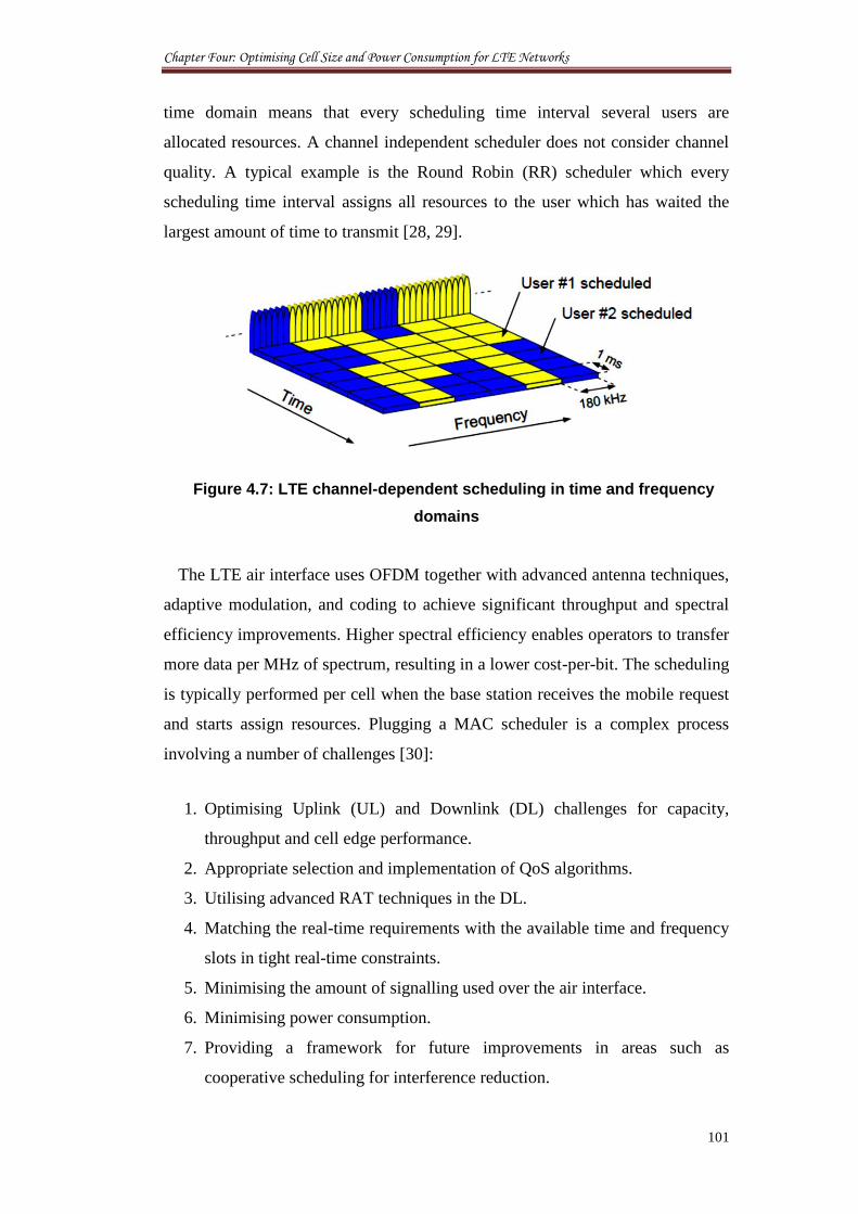
Chapter Four: Optimising Cell Size and Power Consumption for LTE Networks
101
time domain means that every scheduling time interval several users are
allocated resources. A channel independent scheduler does not consider channel
quality. A typical example is the Round Robin (RR) scheduler which every
scheduling time interval assigns all resources to the user which has waited the
largest amount of time to transmit [28, 29].
Figure 4.7: LTE channel-dependent scheduling in time and frequency
domains
The LTE air interface uses OFDM together with advanced antenna techniques,
adaptive modulation, and coding to achieve significant throughput and spectral
efficiency improvements. Higher spectral efficiency enables operators to transfer
more data per MHz of spectrum, resulting in a lower cost-per-bit. The scheduling
is typically performed per cell when the base station receives the mobile request
and starts assign resources. Plugging a MAC scheduler is a complex process
involving a number of challenges [30]:
1. Optimising Uplink (UL) and Downlink (DL) challenges for capacity,
throughput and cell edge performance.
2. Appropriate selection and implementation of QoS algorithms.
3. Utilising advanced RAT techniques in the DL.
4. Matching the real-time requirements with the available time and frequency
slots in tight real-time constraints.
5. Minimising the amount of signalling used over the air interface.
6. Minimising power consumption.
7. Providing a framework for future improvements in areas such as
cooperative scheduling for interference reduction.
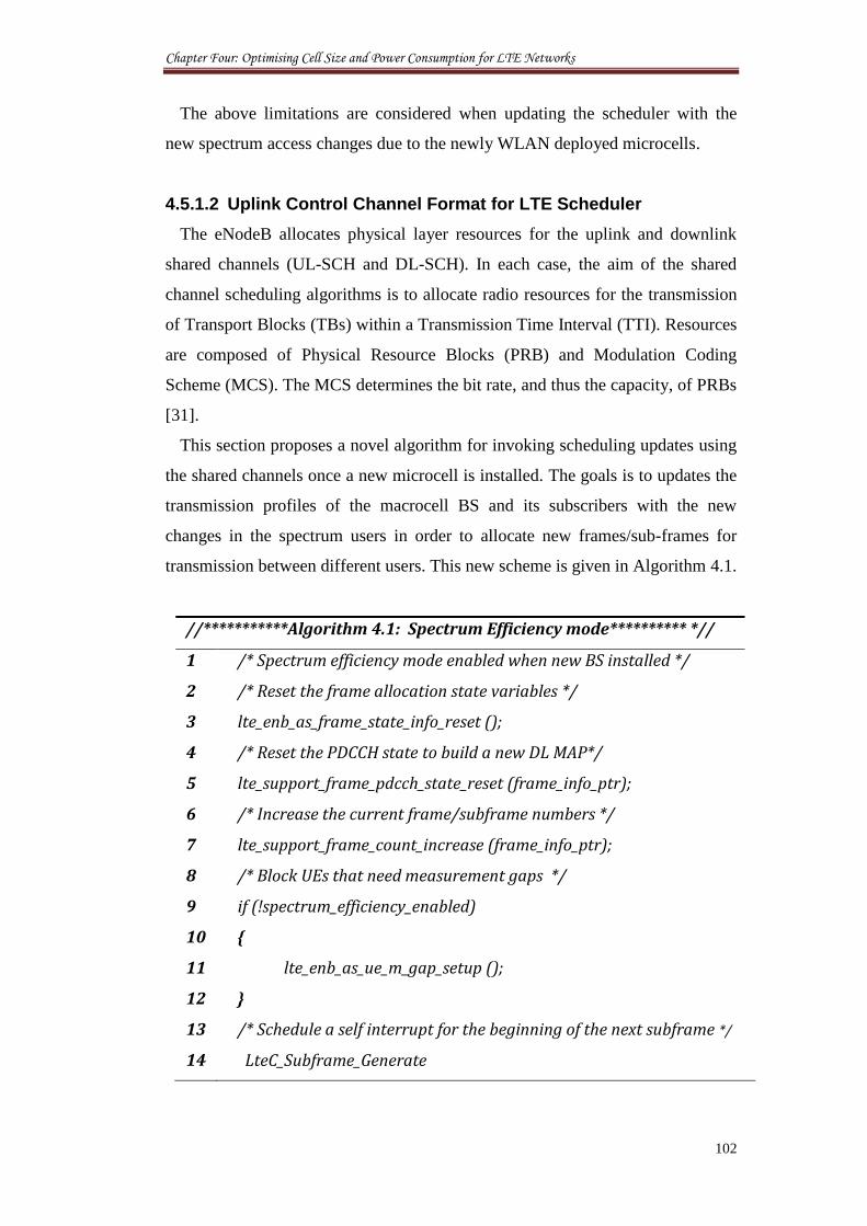
Chapter Four: Optimising Cell Size and Power Consumption for LTE Networks
102
The above limitations are considered when updating the scheduler with the
new spectrum access changes due to the newly WLAN deployed microcells.
4.5.1.2 Uplink Control Channel Format for LTE Scheduler
The eNodeB allocates physical layer resources for the uplink and downlink
shared channels (UL-SCH and DL-SCH). In each case, the aim of the shared
channel scheduling algorithms is to allocate radio resources for the transmission
of Transport Blocks (TBs) within a Transmission Time Interval (TTI). Resources
are composed of Physical Resource Blocks (PRB) and Modulation Coding
Scheme (MCS). The MCS determines the bit rate, and thus the capacity, of PRBs
[31].
This section proposes a novel algorithm for invoking scheduling updates using
the shared channels once a new microcell is installed. The goals is to updates the
transmission profiles of the macrocell BS and its subscribers with the new
changes in the spectrum users in order to allocate new frames/sub-frames for
transmission between different users. This new scheme is given in Algorithm 4.1.
//***********Algorithm 4.1: Spectrum Efficiency mode********** *//
1 /* Spectrum efficiency mode enabled when new BS installed */
2 /* Reset the frame allocation state variables */
3 lte_enb_as_frame_state_info_reset ();
4 /* Reset the PDCCH state to build a new DL MAP*/
5 lte_support_frame_pdcch_state_reset (frame_info_ptr);
6 /* Increase the current frame/subframe numbers */
7 lte_support_frame_count_increase (frame_info_ptr);
8 /* Block UEs that need measurement gaps */
9 if (!spectrum_efficiency_enabled)
10 {
11 lte_enb_as_ue_m_gap_setup ();
12 }
13 /* Schedule a self interrupt for the beginning of the next subframe */
14 LteC_Subframe_Generate
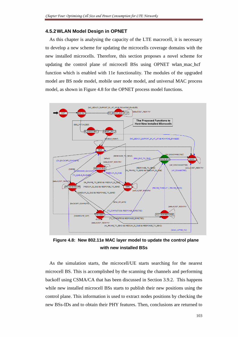
Chapter Four: Optimising Cell Size and Power Consumption for LTE Networks
103
4.5.2 WLAN Model Design in OPNET
As this chapter is analysing the capacity of the LTE macrocell, it is necessary
to develop a new scheme for updating the microcells coverage domains with the
new installed microcells. Therefore, this section proposes a novel scheme for
updating the control plane of microcell BSs using OPNET
function which is enabled with 11e functionality. The modules of the upgraded
model are BS node model, mobile user node model, and universal MAC process
model, as shown in Figure 4.8 for the OPNET process model functions.
Figure 4.8: New 802.11e MAC layer model to update the control plane
with new installed BSs
As the simulation starts, the microcell/UE starts searching for the nearest
microcell BS. This is accomplished by the scanning the channels and performing
backoff using CSMA/CA that has been discussed in Section 3.9.2. This happens
while new installed microcell BSs starts to publish their new positions using the
control plane. This information is used to extract nodes positions by checking the
new BSs-IDs and to obtain their PHY features. Then, conclusions are returned to
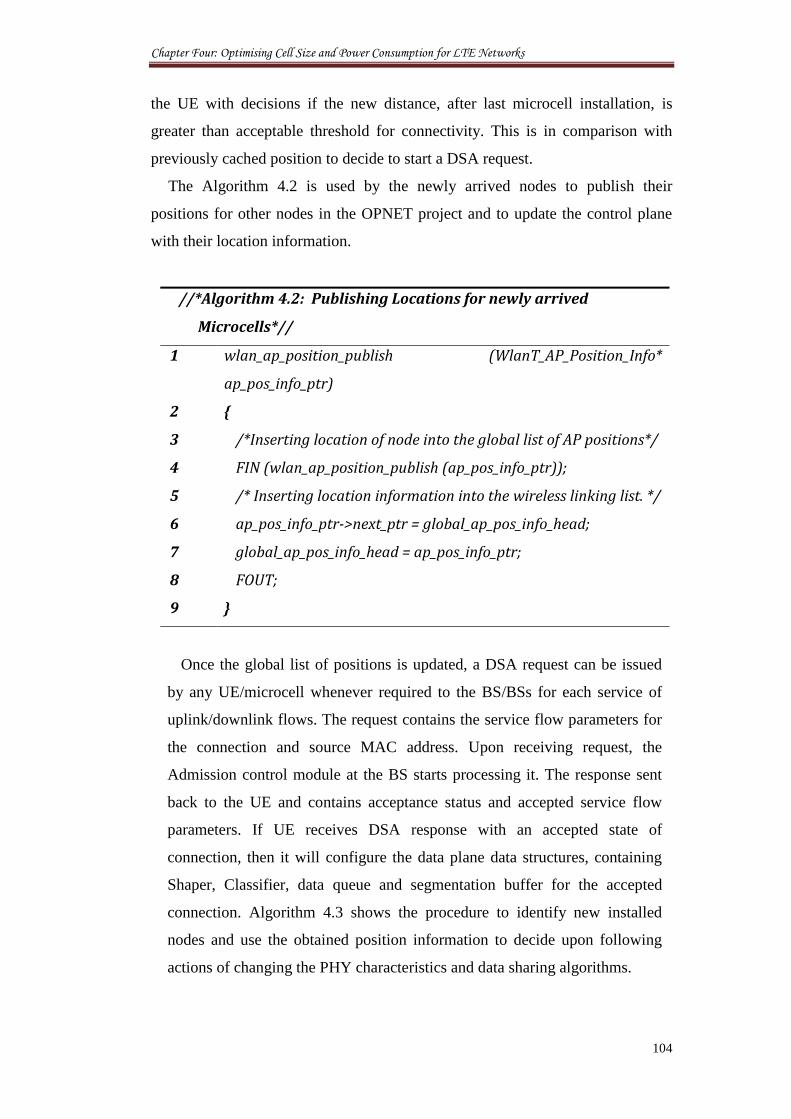
Chapter Four: Optimising Cell Size and Power Consumption for LTE Networks
104
the UE with decisions if the new distance, after last microcell installation, is
greater than acceptable threshold for connectivity. This is in comparison with
previously cached position to decide to start a DSA request.
The Algorithm 4.2 is used by the newly arrived nodes to publish their
positions for other nodes in the OPNET project and to update the control plane
with their location information.
//*Algorithm 4.2: Publishing Locations for newly arrived
Microcells*//
1 wlan_ap_position_publish (WlanT_AP_Position_Info*
ap_pos_info_ptr)
2 {
3 /*Inserting location of node into the global list of AP positions*/
4 FIN (wlan_ap_position_publish (ap_pos_info_ptr));
5 /* Inserting location information into the wireless linking list. */
6 ap_pos_info_ptr->next_ptr = global_ap_pos_info_head;
7 global_ap_pos_info_head = ap_pos_info_ptr;
8 FOUT;
9 }
Once the global list of positions is updated, a DSA request can be issued
by any UE/microcell whenever required to the BS/BSs for each service of
uplink/downlink flows. The request contains the service flow parameters for
the connection and source MAC address. Upon receiving request, the
Admission control module at the BS starts processing it. The response sent
back to the UE and contains acceptance status and accepted service flow
parameters. If UE receives DSA response with an accepted state of
connection, then it will configure the data plane data structures, containing
Shaper, Classifier, data queue and segmentation buffer for the accepted
connection. Algorithm 4.3 shows the procedure to identify new installed
nodes and use the obtained position information to decide upon following
actions of changing the PHY characteristics and data sharing algorithms.
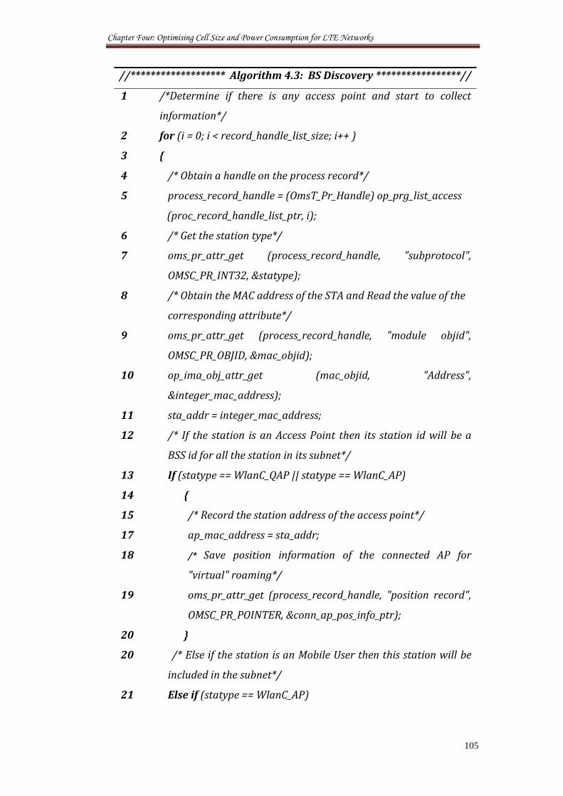
Chapter Four: Optimising Cell Size and Power Consumption for LTE Networks
105
//******************* Algorithm 4.3: BS Discovery *****************//
1 /*Determine if there is any access point and start to collect
information*/
2 for (i = 0; i < record_handle_list_size; i++ )
3 {
4 /* Obtain a handle on the process record*/
5 process_record_handle = (OmsT_Pr_Handle) op_prg_list_access
(proc_record_handle_list_ptr, i);
6 /* Get the station type*/
7 oms_pr_attr_get (process_record_handle, "subprotocol",
OMSC_PR_INT32, &statype);
8 /* Obtain the MAC address of the STA and Read the value of the
corresponding attribute*/
9 oms_pr_attr_get (process_record_handle, "module objid",
OMSC_PR_OBJID, &mac_objid);
10 op_ima_obj_attr_get (mac_objid, "Address",
&integer_mac_address);
11 sta_addr = integer_mac_address;
12 /* If the station is an Access Point then its station id will be a
BSS id for all the station in its subnet*/
13 If (statype == WlanC_QAP || statype == WlanC_AP)
14 {
15 /* Record the station address of the access point*/
17 ap_mac_address = sta_addr;
18 /* Save position information of the connected AP for
"virtual" roaming*/
19 oms_pr_attr_get (process_record_handle, "position record",
OMSC_PR_POINTER, &conn_ap_pos_info_ptr);
20 }
20 /* Else if the station is an Mobile User then this station will be
included in the subnet*/
21 Else if (statype == WlanC_AP)
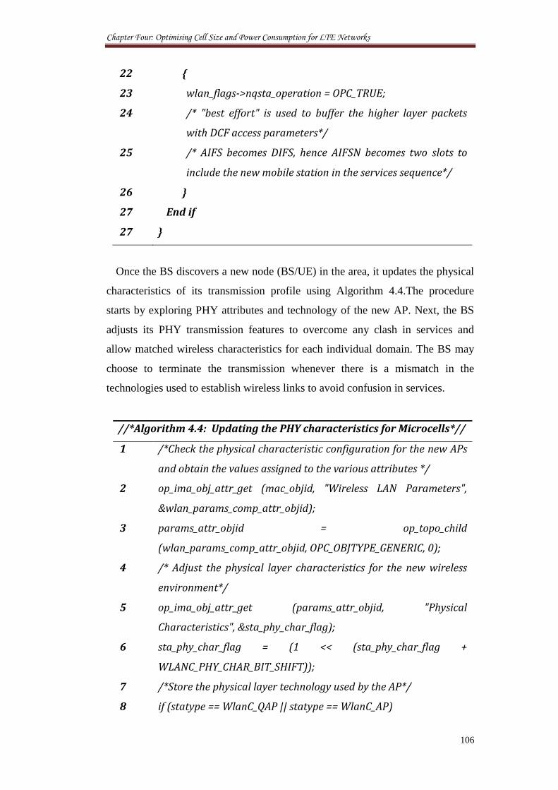
Chapter Four: Optimising Cell Size and Power Consumption for LTE Networks
106
22 {
23 wlan_flags->nqsta_operation = OPC_TRUE;
24 /* "best effort" is used to buffer the higher layer packets
with DCF access parameters*/
25 /* AIFS becomes DIFS, hence AIFSN becomes two slots to
include the new mobile station in the services sequence*/
26 }
27 End if
27 }
Once the BS discovers a new node (BS/UE) in the area, it updates the physical
characteristics of its transmission profile using Algorithm 4.4.The procedure
starts by exploring PHY attributes and technology of the new AP. Next, the BS
adjusts its PHY transmission features to overcome any clash in services and
allow matched wireless characteristics for each individual domain. The BS may
choose to terminate the transmission whenever there is a mismatch in the
technologies used to establish wireless links to avoid confusion in services.
//*Algorithm 4.4: Updating the PHY characteristics for Microcells*//
1 /*Check the physical characteristic configuration for the new APs
and obtain the values assigned to the various attributes */
2 op_ima_obj_attr_get (mac_objid, "Wireless LAN Parameters",
&wlan_params_comp_attr_objid);
3 params_attr_objid = op_topo_child
(wlan_params_comp_attr_objid, OPC_OBJTYPE_GENERIC, 0);
4 /* Adjust the physical layer characteristics for the new wireless
environment*/
5 op_ima_obj_attr_get (params_attr_objid, "Physical
Characteristics", &sta_phy_char_flag);
6 sta_phy_char_flag = (1 << (sta_phy_char_flag +
WLANC_PHY_CHAR_BIT_SHIFT));
7 /*Store the physical layer technology used by the AP*/
8 if (statype == WlanC_QAP || statype == WlanC_AP)
Chapter Four: Optimising Cell Size and Power Consumption for LTE Networks
107
9 {
10 ap_phy_char_flag = sta_phy_char_flag;
11 ap_ht_info_ptr = sta_ht_info_ptr;
12 }
13 /* Mismatching physical layer technologies within the same BSS
are not allowed*/
14 if (sta_phy_char_flag != phy_char_flag)
15 {
16 if (wlan_bss_phy_char_compatability_check (phy_char_flag,
sta_phy_char_flag) == OPC_FALSE)
17 {
18 /*Terminate transmission*/
19 }
20 else
21 {
22 /*Start formulating wireless link*/
23 }
The above algorithms are incorporated into the MAC layers of the LTE and
WLAN nodes to perform the capacity studies given in the following sections.
4.6 Optimising Cognitive Network Architecture
In order to provide a vision for optimising the cognitive radio systems
architectures using the above assumptions and scenarios, a big-sized network
model was developed using Opnet simulator to examine the overall capacity of
heterogeneous WLAN and LTE network environment. The ultimate goal is to
create a threshold of performance for the numbers of newly installed microcells
as given in Section 4.5.
4.6.1 System Setup
Mixed Opnet simulation environments were created from mobile ad-hoc
network (MANET) and IEEE 802.11e, as the primary and secondary networks [1
- 3]. Two end-users were registered to each macrocell and microcell fixed station,
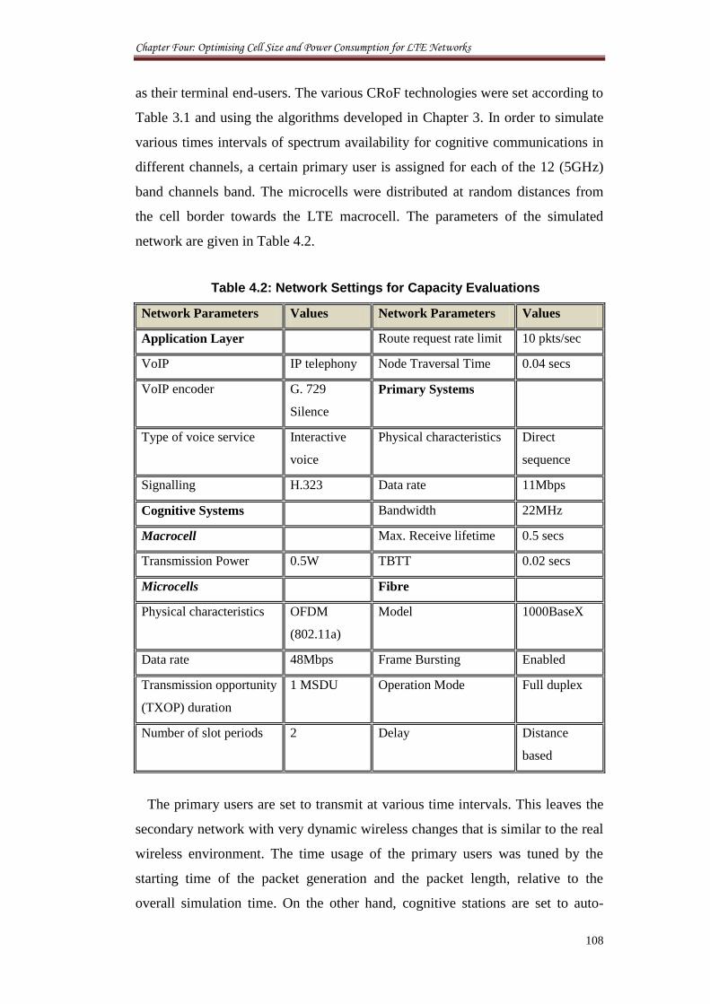
Chapter Four: Optimising Cell Size and Power Consumption for LTE Networks
108
as their terminal end-users. The various CRoF technologies were set according to
Table 3.1 and using the algorithms developed in Chapter 3. In order to simulate
various times intervals of spectrum availability for cognitive communications in
different channels, a certain primary user is assigned for each of the 12 (5GHz)
band channels band. The microcells were distributed at random distances from
the cell border towards the LTE macrocell. The parameters of the simulated
network are given in Table 4.2.
Table 4.2: Network Settings for Capacity Evaluations
Network Parameters Values Network Parameters Values
Application Layer Route request rate limit 10 pkts/sec
VoIP IP telephony Node Traversal Time 0.04 secs
VoIP encoder G. 729
Silence
Primary Systems
Type of voice service Interactive
voice
Physical characteristics Direct
sequence
Signalling H.323 Data rate 11Mbps
Cognitive Systems Bandwidth 22MHz
Macrocell Max. Receive lifetime 0.5 secs
Transmission Power 0.5W TBTT 0.02 secs
Microcells Fibre
Physical characteristics OFDM
(802.11a)
Model 1000BaseX
Data rate 48Mbps Frame Bursting Enabled
Transmission opportunity
(TXOP) duration
1 MSDU Operation Mode Full duplex
Number of slot periods 2 Delay Distance
based
The primary users are set to transmit at various time intervals. This leaves the
secondary network with very dynamic wireless changes that is similar to the real
wireless environment. The time usage of the primary users was tuned by the
starting time of the packet generation and the packet length, relative to the
overall simulation time. On the other hand, cognitive stations are set to auto-
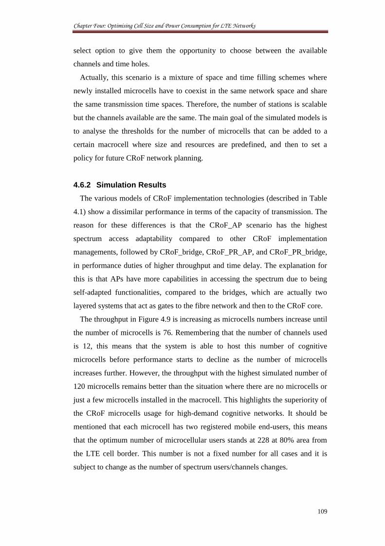
Chapter Four: Optimising Cell Size and Power Consumption for LTE Networks
109
select option to give them the opportunity to choose between the available
channels and time holes.
Actually, this scenario is a mixture of space and time filling schemes where
newly installed microcells have to coexist in the same network space and share
the same transmission time spaces. Therefore, the number of stations is scalable
but the channels available are the same. The main goal of the simulated models is
to analyse the thresholds for the number of microcells that can be added to a
certain macrocell where size and resources are predefined, and then to set a
policy for future CRoF network planning.
4.6.2 Simulation Results
The various models of CRoF implementation technologies (described in Table
4.1) show a dissimilar performance in terms of the capacity of transmission. The
reason for these differences is that the CRoF_AP scenario has the highest
spectrum access adaptability compared to other CRoF implementation
managements, followed by CRoF_bridge, CRoF_PR_AP, and CRoF_PR_bridge,
in performance duties of higher throughput and time delay. The explanation for
this is that APs have more capabilities in accessing the spectrum due to being
self-adapted functionalities, compared to the bridges, which are actually two
layered systems that act as gates to the fibre network and then to the CRoF core.
The throughput in Figure 4.9 is increasing as microcells numbers increase until
the number of microcells is 76. Remembering that the number of channels used
is 12, this means that the system is able to host this number of cognitive
microcells before performance starts to decline as the number of microcells
increases further. However, the throughput with the highest simulated number of
120 microcells remains better than the situation where there are no microcells or
just a few microcells installed in the macrocell. This highlights the superiority of
the CRoF microcells usage for high-demand cognitive networks. It should be
mentioned that each microcell has two registered mobile end-users, this means
that the optimum number of microcellular users stands at 228 at 80% area from
the LTE cell border. This number is not a fixed number for all cases and it is
subject to change as the number of spectrum users/channels changes.
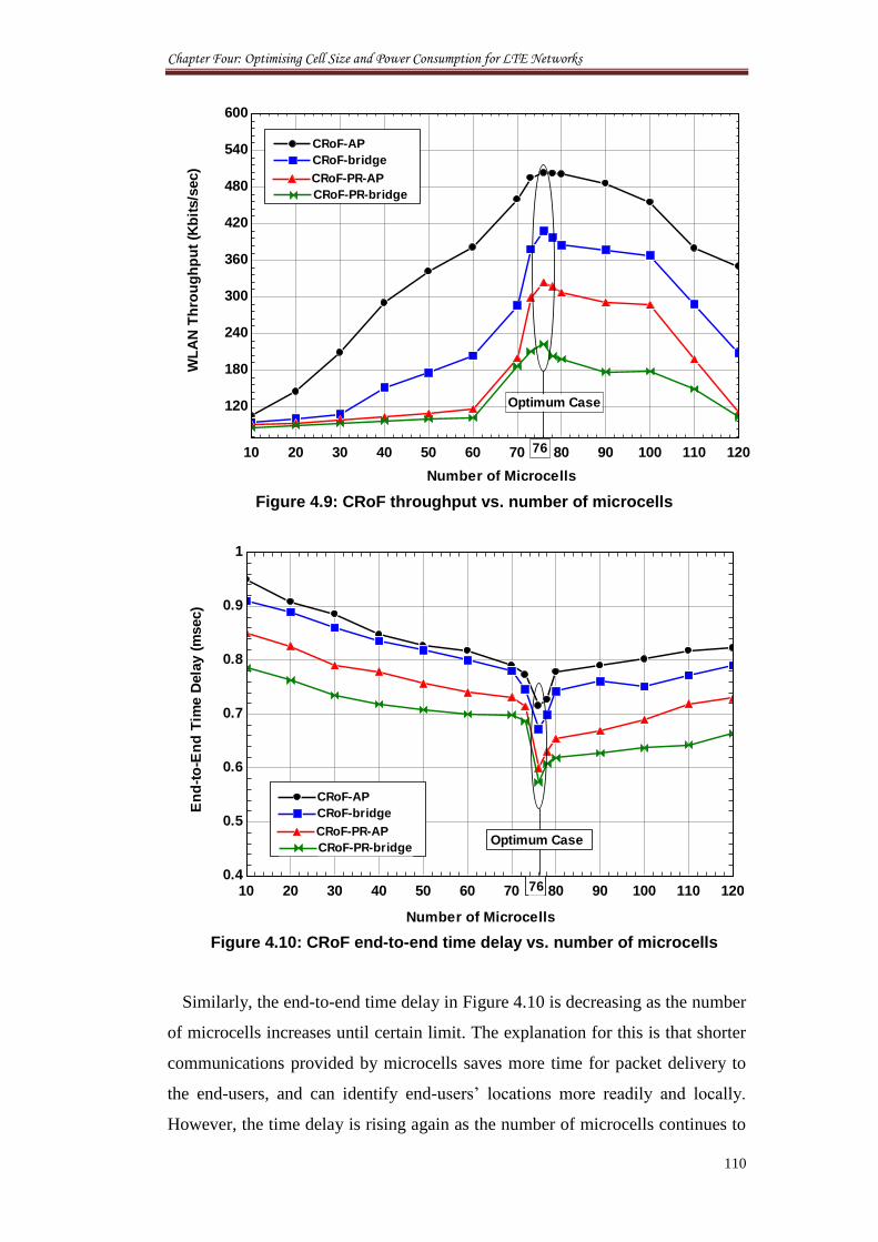
Chapter Four: Optimising Cell Size and Power Consumption for LTE Networks
110
Figure 4.9: CRoF throughput vs. number of microcells
Figure 4.10: CRoF end-to-end time delay vs. number of microcells
Similarly, the end-to-end time delay in Figure 4.10 is decreasing as the number
of microcells increases until certain limit. The explanation for this is that shorter
communications provided by microcells saves more time for packet delivery to
the end-users, and can identify end-users’ locations more readily and locally.
However, the time delay is rising again as the number of microcells continues to
10 20 30 40 50 60 70 80 90 100 110 120
120
180
240
300
360
420
480
540
600
76
Optimum Case
CRoF-APCRoF-AP
CRoF-bridgeCRoF-bridge
CRoF-PR-APCRoF-PR-AP
CRoF-PR-bridgeCRoF-PR-bridgeW
LA
N T
hro
ug
hp
ut
(Kb
its/s
ec)
Number of Microcells
10 20 30 40 50 60 70 80 90 100 110 1200.4
0.5
0.6
0.7
0.8
0.9
1
Number of Microcells
En
d-t
o-E
nd
Tim
e D
ela
y (
msec)
76
Optimum Case
CRoF-APCRoF-AP
CRoF-bridgeCRoF-bridge
CRoF-PR-APCRoF-PR-AP
CRoF-PR-bridgeCRoF-PR-bridge
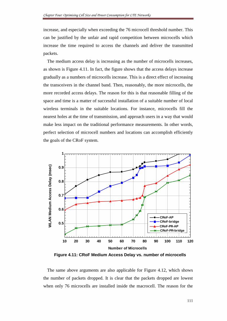
Chapter Four: Optimising Cell Size and Power Consumption for LTE Networks
111
increase, and especially when exceeding the 76 microcell threshold number. This
can be justified by the unfair and rapid competition between microcells which
increase the time required to access the channels and deliver the transmitted
packets.
The medium access delay is increasing as the number of microcells increases,
as shown is Figure 4.11. In fact, the figure shows that the access delays increase
gradually as a numbers of microcells increase. This is a direct effect of increasing
the transceivers in the channel band. Then, reasonably, the more microcells, the
more recorded access delays. The reason for this is that reasonable filling of the
space and time is a matter of successful installation of a suitable number of local
wireless terminals in the suitable locations. For instance, microcells fill the
nearest holes at the time of transmission, and approach users in a way that would
make less impact on the traditional performance measurements. In other words,
perfect selection of microcell numbers and locations can accomplish efficiently
the goals of the CRoF system.
Figure 4.11: CRoF Medium Access Delay vs. number of microcells
The same above arguments are also applicable for Figure 4.12, which shows
the number of packets dropped. It is clear that the packets dropped are lowest
when only 76 microcells are installed inside the macrocell. The reason for the
10 20 30 40 50 60 70 80 90 100 110 120
0.5
0.6
0.7
0.8
0.9
1
CRoF-APCRoF-AP
CRoF-bridgeCRoF-bridge
CRoF-PR-APCRoF-PR-AP
CRoF-PR-bridgeCRoF-PR-bridge
WL
AN
Med
ium
Access D
ela
y (
msec)
Number of Microcells
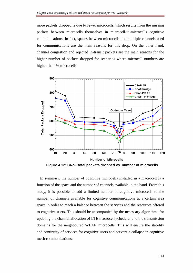
Chapter Four: Optimising Cell Size and Power Consumption for LTE Networks
112
more packets dropped is due to fewer microcells, which results from the missing
packets between microcells themselves in microcell-to-microcells cognitive
communications. In fact, spaces between microcells and multiple channels used
for communications are the main reasons for this drop. On the other hand,
channel congestion and rejected in-transit packets are the main reasons for the
higher number of packets dropped for scenarios where microcell numbers are
higher than 76 microcells.
Figure 4.12: CRoF total packets dropped vs. number of microcells
In summary, the number of cognitive microcells installed in a macrocell is a
function of the space and the number of channels available in the band. From this
study, it is possible to add a limited number of cognitive microcells to the
number of channels available for cognitive communications at a certain area
space in order to reach a balance between the services and the resources offered
to cognitive users. This should be accompanied by the necessary algorithms for
updating the channel allocation of LTE macrocell scheduler and the transmission
domains for the neighboured WLAN microcells. This will ensure the stability
and continuity of services for cognitive users and prevent a collapse in cognitive
mesh communications.
10 20 30 40 50 60 70 80 90 100 110 120400
500
600
700
800
900
Number of Microcells
To
tal
Packets
Dro
pp
ed
76
Optimum Case
CRoF-APCRoF-AP
CRoF-bridgeCRoF-bridge
CRoF-PR-APCRoF-PR-AP
CRoF-PR-bridgeCRoF-PR-bridge
Chapter Four: Optimising Cell Size and Power Consumption for LTE Networks
113
4.7 Power Consumption Planning
Power consumption planning is the first step in the process of dimensioning
the cell size for any mobile network. It gives an evaluation of the system
resources needed to provide service in the deployment zone with the specified
system parameters, without any load concern. Therefore, it gives a clear idea
about the allocation of the resources required to cover the area under
consideration. This allows an efficient coverage that enables transmitters and
receivers to communicate easily and cost-efficiently. One example of the
coverage development consists of evaluation of radio link budgets. In this way,
the maximum throughput is calculated based on the required SNR level at the
receiver, taking into account the level of the interference caused by traffic [32].
This study covers LTE Coverage Planning with WLAN microcell deployment.
Power consumption figures are investigated for deployments with increasing
numbers of micro sites provided with simple models for the power consumption
of different base station types in order to improve the overall energy
consumption figures of cognitive network.
4.7.1 Case Study
To continue the optimisation of the macro-to-micro cellular system given in
the previous sections, a power consumption model is proposed for the
LTE/WLAN base station with realistic factors for heterogeneous cell
deployments. This power consumption model has two parts, modelled
simultaneously. The first part describes the static power consumption and gives a
power figure for a macro base station with no users. Then, depending on the load
situation, a dynamic power consumption part is added to the static power in order
to calculate the overall consumed power. It is assumed that the optimum cell size
is strongly affected by these changes.
Studies have identified the access network of cellular networks, more precisely
the base stations, to be the major contributor to the total power consumption [33].
Although, there are other methods to reduce power consumption of a cellular
system using more efficient base stations, the focus is on evaluating the possible
energy saving in OFDM networks through low power micro BS deployment
alongside macrocell BSs. In OFDM networks, offloading from macrocells to
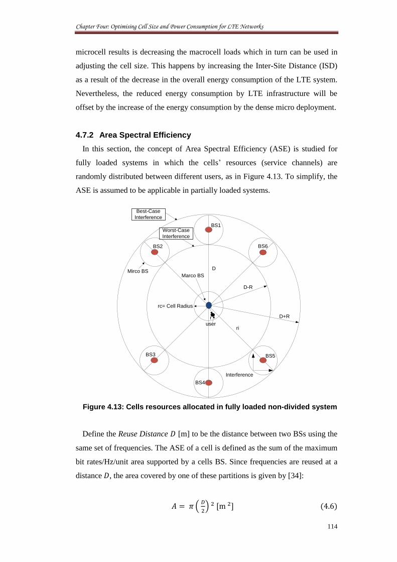
Chapter Four: Optimising Cell Size and Power Consumption for LTE Networks
114
microcell results is decreasing the macrocell loads which in turn can be used in
adjusting the cell size. This happens by increasing the Inter-Site Distance (ISD)
as a result of the decrease in the overall energy consumption of the LTE system.
Nevertheless, the reduced energy consumption by LTE infrastructure will be
offset by the increase of the energy consumption by the dense micro deployment.
4.7.2 Area Spectral Efficiency
In this section, the concept of Area Spectral Efficiency (ASE) is studied for
fully loaded systems in which the cells’ resources (service channels) are
randomly distributed between different users, as in Figure 4.13. To simplify, the
ASE is assumed to be applicable in partially loaded systems.
Figure 4.13: Cells resources allocated in fully loaded non-divided system
Define the Reuse Distance [m] to be the distance between two BSs using the
same set of frequencies. The ASE of a cell is defined as the sum of the maximum
bit rates/Hz/unit area supported by a cells BS. Since frequencies are reused at a
distance , the area covered by one of these partitions is given by [34]:
(
) [ ]
rc= Cell Radius
D+R
Interference
D-R
Worst-Case
Interference
Best-Case
Interference
ri
D
BS1
BS2
BS3
BS4
BS5
BS6
r
user
Marco BSMirco BS

Chapter Four: Optimising Cell Size and Power Consumption for LTE Networks
115
The ASE, [b/s/Hz/ ] is therefore calculated by [34]:
∑
( )
where is the total number of active serviced channels per cell, [b/s] is the
maximum data rate of the user, and [Hz] is the total allocated bandwidth
per cell. We define as the maximum rate to be the Shannon capacity of the
user in the cell, and the bandwidth allocated to that user.
4.7.3 Area Power Consumption
In general, observing the simple power consumption per site is inappropriate
for comparing networks of differing site densities, since increasing distances
generate larger coverage areas. Therefore it might be more reasonable to identify
the power consumption for each tier of stations individually. Therefore we
identify the following:
Area power consumption of one macro cell is given as [35]:
(
)
Area power consumption of one microcell is given as [35]:
(
)
where and are the average power consumed by macro and micro sites,
respectively.
In order to assess that the power consumption of the network is relative to its
size, we propose the notion of area power consumption as the average power
consumed in a reference cell divided by the corresponding cell size measured in
Watts per square kilometre. With an average of N micro sites in a reference cell
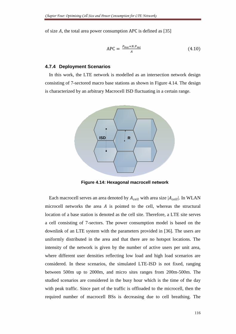
Chapter Four: Optimising Cell Size and Power Consumption for LTE Networks
116
of size , the total area power consumption is defined as [35]
4.7.4 Deployment Scenarios
In this work, the LTE network is modelled as an intersection network design
consisting of 7-sectored macro base stations as shown in Figure 4.14. The design
is characterized by an arbitrary Macrocell ISD fluctuating in a certain range.
Figure 4.14: Hexagonal macrocell network
Each macrocell serves an area denoted by with area size | |. In WLAN
microcell networks the area is pointed to the cell, whereas the structural
location of a base station is denoted as the cell site. Therefore, a LTE site serves
a cell consisting of 7-sectors. The power consumption model is based on the
downlink of an LTE system with the parameters provided in [36]. The users are
uniformly distributed in the area and that there are no hotspot locations. The
intensity of the network is given by the number of active users per unit area,
where different user densities reflecting low load and high load scenarios are
considered. In these scenarios, the simulated LTE-ISD is not fixed, ranging
between 500m up to 2000m, and micro sites ranges from 200m-500m. The
studied scenarios are considered in the busy hour which is the time of the day
with peak traffic. Since part of the traffic is offloaded to the microcell, then the
required number of macrocell BSs is decreasing due to cell breathing. The
RISD
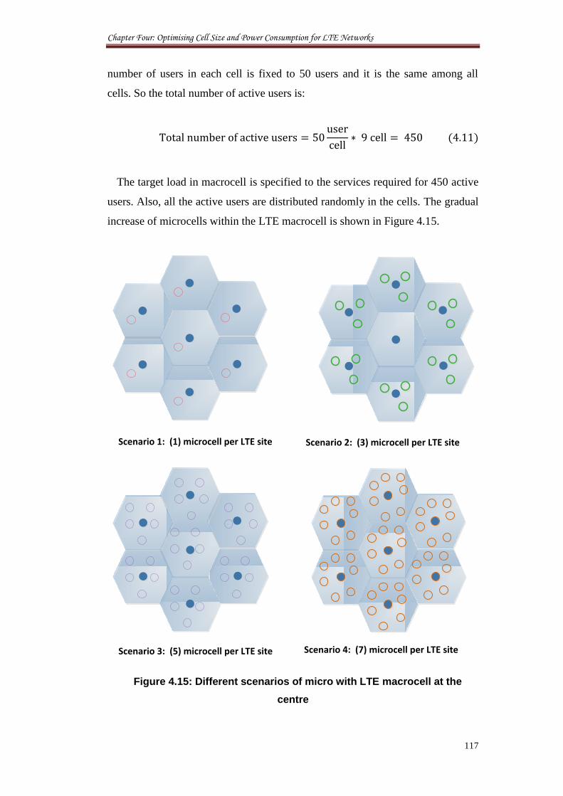
Chapter Four: Optimising Cell Size and Power Consumption for LTE Networks
117
number of users in each cell is fixed to 50 users and it is the same among all
cells. So the total number of active users is:
The target load in macrocell is specified to the services required for 450 active
users. Also, all the active users are distributed randomly in the cells. The gradual
increase of microcells within the LTE macrocell is shown in Figure 4.15.
Figure 4.15: Different scenarios of micro with LTE macrocell at the
centre
Scenario 1: (1) microcell per LTE site Scenario 2: (3) microcell per LTE site
Scenario 4: (7) microcell per LTE siteScenario 3: (5) microcell per LTE site
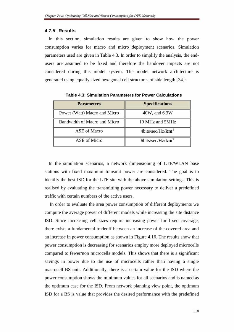
Chapter Four: Optimising Cell Size and Power Consumption for LTE Networks
118
4.7.5 Results
In this section, simulation results are given to show how the power
consumption varies for macro and micro deployment scenarios. Simulation
parameters used are given in Table 4.3. In order to simplify the analysis, the end-
users are assumed to be fixed and therefore the handover impacts are not
considered during this model system. The model network architecture is
generated using equally sized hexagonal cell structures of side length [34]:
Table 4.3: Simulation Parameters for Power Calculations
Parameters Specifications
Power (Watt) Macro and Micro 40W, and 6.3W
Bandwidth of Macro and Micro 10 MHz and 5MHz
ASE of Macro 4bits/sec/Hz/
ASE of Micro 6bits/sec/Hz/
In the simulation scenarios, a network dimensioning of LTE/WLAN base
stations with fixed maximum transmit power are considered. The goal is to
identify the best ISD for the LTE site with the above simulation settings. This is
realised by evaluating the transmitting power necessary to deliver a predefined
traffic with certain numbers of the active users.
In order to evaluate the area power consumption of different deployments we
compute the average power of different models while increasing the site distance
ISD. Since increasing cell sizes require increasing power for fixed coverage,
there exists a fundamental tradeoff between an increase of the covered area and
an increase in power consumption as shown in Figure 4.16. The results show that
power consumption is decreasing for scenarios employ more deployed microcells
compared to fewer/non microcells models. This shows that there is a significant
savings in power due to the use of microcells rather than having a single
macrocell BS unit. Additionally, there is a certain value for the ISD where the
power consumption shows the minimum values for all scenarios and is named as
the optimum case for the ISD. From network planning view point, the optimum
ISD for a BS is value that provides the desired performance with the predefined
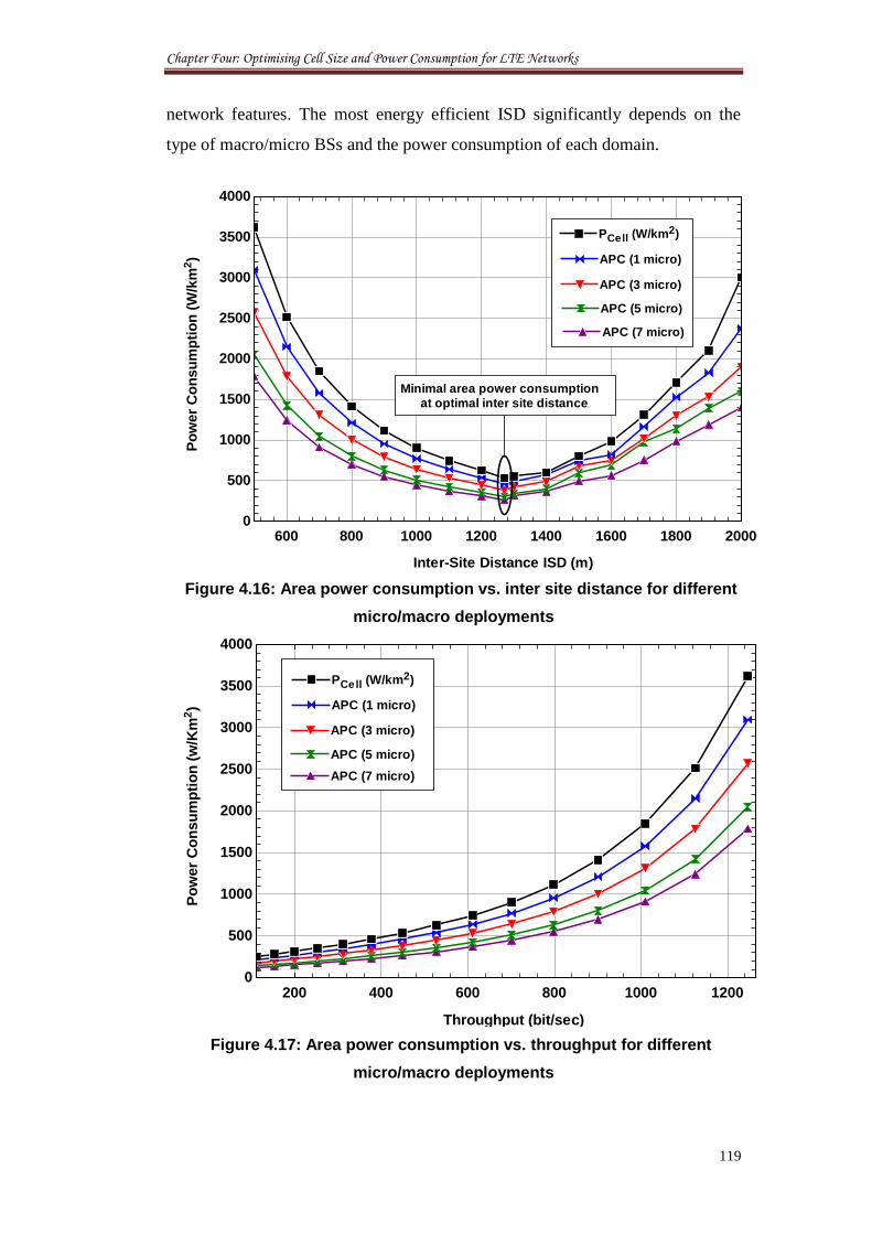
Chapter Four: Optimising Cell Size and Power Consumption for LTE Networks
119
network features. The most energy efficient ISD significantly depends on the
type of macro/micro BSs and the power consumption of each domain.
Figure 4.16: Area power consumption vs. inter site distance for different
micro/macro deployments
Figure 4.17: Area power consumption vs. throughput for different
micro/macro deployments
600 800 1000 1200 1400 1600 1800 20000
500
1000
1500
2000
2500
3000
3500
4000P
ow
er
Co
nsu
mp
tio
n (
W/k
m2)
Inter-Site Distance ISD (m)
APC (7 micro)APC (7 micro)
APC (5 micro)APC (5 micro)
APC (3 micro)APC (3 micro)
APC (1 micro)APC (1 micro)
PCell (W/km2)PCell (W/km2)
Minimal area power consumption
at optimal inter site distance
200 400 600 800 1000 12000
500
1000
1500
2000
2500
3000
3500
4000
Throughput (bit/sec)
APC (7 micro)APC (7 micro)
APC (5 micro)APC (5 micro)
APC (3 micro)APC (3 micro)
APC (1 micro)APC (1 micro)
PCell (W/km2)PCell (W/km2)
Po
wer
Co
nsu
mp
tio
n (
w/K
m2)
Chapter Four: Optimising Cell Size and Power Consumption for LTE Networks
120
The deployment of micro sites lead to a reduction in power consumption by
relaxing the coverage requirements as it provides significant gains in spectral
efficiency in high load scenarios. Obviously, small base stations are intended to
increase throughput locally by exploiting good propagation and transmission
opportunities. This effect is shown in Figure 4.17 where the power consumed is
increasing as a function of the increase in the area throughput. Similar to the
previous system performance, scenarios that employ higher number of microcells
show lower values of power consumption for the same throughput values as the
lower-microcells/macro scenarios.
In this section we analysed the optimum cellular network deployments with
respect to the average number of micro sites per macro cell as well as the macro
cell size. The area power consumption was calculated for different deployment
scenarios as well as the throughput.
4.8 Conclusion
This Chapter proposes thresholds for installing microcells in cognitive mesh
planning of the CRoF system. In this regard, the scenarios for adding cognitive
microcells are studied for two main coexistence methods: Space Filling and Time
Filling. Cognitive microcells’ adapted coverage areas are presented through
Space Filling with the new standard 802.11af. The Spectrum Load Smoothing
principle is used for time utilisation and/or adding more microcells to the
available band channels in the Time Filling method. A capacity model for
subcarrier allocation in multiple access OFDM systems is proposed using novel
algorithms for hosting new arrived microcells. The goals were to explore the
total density constraints of users at pre-identified cell zones and numbers of
channels. The subcarrier allocation algorithms are combined with previous
chapter solutions for cognitive microcellular systems to present simulation
results for wireless multi-access microcells in LTE cells. At the end, tis chapter
shows that the deployment of micro sites allows to significantly decreasing the
area power consumption in the network while still achieving certain area
throughput targets and efficient services delivery. The chapter combines the
network architecture density equipments to the available recourses in the field in
order to attain an efficient architecture for the future cognitive networks.
Chapter Four: Optimising Cell Size and Power Consumption for LTE Networks
121
4.9 References
[1] J. Robson and L. Hiley, “Easy small cell backhaul,” Cambridge Broadband
Network, white paper, February 2012.
[2] R. Madan, J. Borran, A. Sampath, N. Bhushan, A. Khandekar, and T. Ji,
“Cell association and interference coordination in heterogeneous LTE-A
cellular networks,” IEEE JSAC-Special issue on Cooperative
Communications in MIMO Cellular Networks, vol. 28, no. 9, 2010, pp.
1479 - 1489.
[3] C. Y. Lee, H. G. Kang, and T. Park, “A Dynamic Sectorization of
Microcells for Balanced Traffic in CDMA: Genetic Algorithms Approach,”
IEEE Transactions on Vehicular Technology, vol. 51, no. 1, 2002, pp. 63 -
72.
[4] M. Sauer, A. Kobyakov, and J. George, “Radio Over Fiber for Picocellular
Network Architectures,” Journal of Lightwave Technology, vol. 25, no. 11,
2007, pp. 3301 - 3320.
[5] H. Li, A. Attar, V. C. M. Leung , and Q. Pang, “Collision Avoidance and
Mitigation in Cognitive Wireless Local Area Network over Fibre,” In
proceedings of the 1st Intern Conf on Evolving Internet (INTERNET’09),
Canada, 2009, pp. 133 - 138.
[6] S. Ramanath, E. Altman, V. Kumar and M. Debbah, “Optimizing cell Size
in Pica-cell networks,” In proceedings of the 7th
International Symposium
on Modeling and Optimization in Mobile, Ad Hoc, and Wireless Networks
(WiOPT 2009), Korea, June 2009, pp. 1 - 9.
[7] Z. Hasan, H. Boostanimehr, and V. K. Bhargava, “Green Cellular
Networks: A Survey, Some Research Issues and Challenges,” IEEE
Communications Surveys & Tutorials, vol. 13, no. 4, 2011, pp. 524 - 540.
[8] A. J Fehske, F. Richter, and G. P Fettweis, “Energy Efficiency
Improvements through Micro Sites in Cellular Mobile Radio Networks,” In
proceedings of the 2nd
International Workshop on Green Communications
(GLOBECOM 2009), Hawaii, USA, 2009, pp. 1 - 5.
[9] IEEE 802.11 Working Group, Task Group af, Internet:
http://grouper.ieee.org/groups/802/11/Reports/tgaf_update.htm, Accessed:
July 21, 2012.
Chapter Four: Optimising Cell Size and Power Consumption for LTE Networks
122
[10] IEEE 802.19 Wireless Coexistence Working Group, Internet:
http://www.ieee802.org, Accessed: July 21, 2012.
[11] M. D. Mueck, M. Di Renzo, and M. Debbah, “Opportunistic Relaying for
Cognitive Radio Enhanced Cellular Networks: Infrastructure and Initial
Results,” In proceedings of the 5th
IEEE International Symposium on
Wireless Pervasive Computing (ISWPC), Italy, 2010, pp. 556 - 561.
[12] M. Mueck, G. Dimitrakopoulos, K. Tsagkaris, J. Gebert, K. Nolte, S. Filin,
H. Harada, G. Baldini, J. Perez-Romero, O. Salient, F. Casadevall, and A.
Ahtiainen, “ETSI Reconfigurable Radio Systems – Status and Future
Directions on Software Defined Radio and Cognitive Radio Standards,” In
proceedings of the 20th
IEEE International Symposium on Personal, Indoor
and Mobile Radio Communications, Germany, 2009, pp. 1 - 5.
[13] A. Al-Dulaimi, H. S. Al-Raweshidy, J. Cosmas, and J. Loo, “Cognitive
Mesh Networks, Cognitive Radio over Fibre for Microcells Application,”
IEEE Vehicular Technology Magazine, vol. 5, no. 3, 2010, pp. 54 - 60.
[14] W. Webb, “Can existing Wi-Fi nodes boost 4G?,” Engineering and
Technology Magazine, vol. 6, issue 12, 12 Jan 2012, pp. 91 - 92.
[15] S. Carlos, B. Gangopadhyay B., A. Arsenio, M. V. Ramkumar, and N. R.
Prasad, “Network Management System for (FUTON-like) Radio-over-
Fiber Infrastructure,” International Journal of Computer and
Communication Technology (IJCCT), vol. 1, no. 2, 2010, pp. 354 -359.
[16] M. R. Kim and S. Jo Yoo, “Distributed Coordination Protocol for Common
Control Channel Selection in Multichannel Ad-hoc Cognitive Radio
Networks,” In proceedings of the 5th
IEEE International Conference on
Wireless and Mobile Computing, Networking and Communications
(WIMOB 2009), Marrakech, Morocco, 2009, pp. 227 - 232.
[17] D. Nussbaum, K. Kalfallah, R. Knopp, C. Moy, A. Nafkha, P. Leray, J.
Delorme, J. Palicot, J. Martin, F. Clermidy, B. Mercier, and R. Pacalet,
“Open Platform for Prototyping of Advanced Software Defined Radio and
Cognitive Radio Techniques,” In proceedings of the 12th
Euromicro
Conference on Digital System Design, Architectures, Methods and Tools,
France, 2009, pp. 435 - 440.
Chapter Four: Optimising Cell Size and Power Consumption for LTE Networks
123
[18] S. Mangold, S. Choi, G. R. Hiertz, O. Klein, and B. Walke, “Analysis Of
IEEE 802.11e For Qos Support In Wireless Lans,” IEEE Wireless
Communication Magazine, vol. 10, no. 6, 2003, pp. 40 - 50.
[19] D. Gu and J. Zhang, “QoS Enhancement in IEEE802.11Wireless Local
Area Networks,” IEEE Communication Magazine, vol. 41, no. 6, 2003, pp.
120 - 124.
[20] Z. Kong, D. H. K. Tsang, B. Bensaou, and D. Gao, “Performance Analysis
of IEEE 802.11e Contention-Based Channel Access,” IEEE Journal on
Selected Areas in Communications (JSAC), vol. 22, no. 10, 2004, pp. 2095
- 2106.
[21] M. Li, H. Zhu, and B. Prabhakaran, “Dynamic priority re-allocation
scheme for quality of service in IEEE 802.11e wireless networks,”
Wireless Networks, vol. 16, no. 3, 2010, pp. 759 - 774.
[22] L. Berlemann and B. Walke, “Spectrum Load Smoothing for Optimized
Spectrum Utilization – Rationale and Algorithm,” In proceedings of the
IEEE Wireless Communications and Networking Conference (WCNC),
New Orleans, USA, 2005, pp. 735 - 740.
[23] R. A. Bhatti, J.-H. Choi, and S.-O. Park, “Quad-Band MIMO Antenna
Array for Portable Wireless Communications Terminals,” IEEE Antennas
and Wireless Propagation Letters, vol. 8, 2009, pp. 129 - 132.
[24] P. C. Cheng, C. Y. D. Sim, and C. H. Lee, “Multi-Band Printed Internal
Monopole Antenna for Mobile Handset Applications,” Journal of
Electromagnetic Waves and Applications, vol. 23, no. 13, 2009, pp. 1733 -
1744.
[25] A. Al-Dulaimi and H. S. Al-Raweshidy, “Multi-Operator Cognitive Radios
Sharing One Channel,” In proceedings of the 7th
ACM International
Symposium on Mobility Management and Wireless Access, Spain, 2009,
pp. 114 - 117.
[26] I. F. Akyildiz, W. Y. Lee, M. C. Vuran, and S. Mohanty, “NeXt
generation/dynamic spectrum access/cognitive radio wireless networks: A
survey,” Journal of Computer Networks, vol. 50, no. 13, 2006, pp. 2127 -
2159.
[27] K. Banawan, M. Abdullah, M. El-Gharabawy, “Comparative study
between Mobile WiMAX (IEEE802.16e based) and 3GPP LTE,” Internet:
Chapter Four: Optimising Cell Size and Power Consumption for LTE Networks
124
http://xa.yimg.com/kq/groups/20725580/2080579529/name/Comparative_s
tudy_between_Mobile_WiMAX_and_LTE_v3.pdf. Accessed: July, 11,
2012.
[28] O. Iosif and I. Banica, “On the Analysis of Packet Scheduling in Downlink
3GPP LTE System,” In proceedings of the 4th International Conference on
Communication Theory, Reliability, and Quality of Service (CTRQ 2011),
Budapest, Hungary, 2011, pp. 99 - 102.
[29] K. Jersenius, “Uplink Channel Dependent Scheduling for Future Cellular
Systems,” Maters thesis, Department of Electrical Engineering, Linköpings
universitet, Linköping, Sweden, 2007.
[30] Roke Technical Report, “LTE eNodeB MAC Scheduler Introduction,”
Roke Manor Research Limited, Hampshire, UK, Technical Report, 2012.
[31] Freescale Semiconductor, Long Term Evolution Protocol Overview, White
Paper, U.S.A, 2010.
[32] A. Rahimian and F. Mehran, “RF Link Budget Analysis in Urban
Propagation Microcell Environment for Mobile Radio Communication
Systems Link Planning,” In proceedings of the International Conference
on Wireless Communications and Signal Processing (WCSP), Nanjing,
China, 2011, pp. 1 - 5.
[33] W. Yu, W. Rhee, S. Boyd , and J. Cioffi, “ Iterative water-filling for
Gaussian vector multiple-access channels,” IEEE Transactions on
Information Theory, vol. 50, no. 1, 2004, pp. 45 - 152.
[34] M. S. Alouini and A. J. Goldsmith, “Area spectral efficiency of cellular
mobile radio systems,” IEEE Transactions on Vehicular Technology, vol.
48, no. 4, 1999, pp. 1047 - 1066.
[35] G. Forney and M. Eyuboglu, “Combined Equalization and Coding using
Precoding,” IEEE Communications Magazine, vol. 29, no. 12, 1991, pp. 25
- 34.
[36] Channel models for HIPERLAN/2 in different indoor scenarios. ETSI
Normalization Committe, Sophia-Antipolis, France, 1998.
Chapter Five: Mobility Management in Cognitive Networks
125
Chapter 5
Mobility Management in
Cognitive Networks
Cognitive networks are accepted as a facilitator of the quest to offer seamless
mobility to users, considering their ever-increasing service demand. This is done
by adopting their operation (proactively or reactively) in responding to external
stimuli. However, the dynamic adaptation between channels known as Spectrum
Handover raises many questions about the validity of the cognitive network
solution in the 4G systems. The handover here is not just a registration with a
new operator station, but it is also a negotiation to get access to the available
channels locally in coexistence with the primary users. Therefore, it is necessary
to develop a novel method for roaming new mobiles moving between microcells
and macrocell coverage areas to reduce unnecessary channel adaptations. This
chapter proposes new entity namely Channel Assigning Agent for managing
spectrum handover, channel allocation, and operator database. The proposed
mechanism retains the same channel used by mobile phone while moving
between different cognitive domains in order to improve network operation by
reducing the unnecessary spectrum handovers. Also, network division into many
zones of services is proposed for which CRoF-BS acts as the core of the zones.
Therefore, a new paradigm for local resources sharing emerges through these
architectural network modifications. This multi-zoned structure formulates new
models of cell handover between the CRoF zones and the traditional cognitive
networks.
Chapter Five: Mobility Management in Cognitive Networks
126
5.1 Introduction
The key enabling technology of dynamic spectrum access techniques is CR
technology, which provides the capability to share the wireless channel with
licensed users in an opportunistic manner. Cognitive networks are envisioned to
provide high bandwidth to mobile users via heterogeneous wireless architectures
and dynamic spectrum access techniques [1]. However, the need for CRs is
motivated by many factors. Principally, though, the need for cognition is driven
by the complexity of the radio systems themselves. The existence of SDRs
capable of implementing a near endless number of different waveforms with
different modulation schemes, power levels, error control codes, carrier
frequencies, etc., means that controlling the radio becomes a problem of
combinatorial optimisation [2].
There are two major approaches in cognitive radio: dynamic spectrum
allocation and opportunistic spectrum access. For dynamic spectrum allocation,
information on spectrum occupation is used for channel allocation and planning
on a long-term basis. On the other hand, with opportunistic spectrum access,
instantaneous information of channel usage by a primary user is observed and
utilised to grant access to secondary users to increase utilisation on a short term
basis [3]. Earlier research done by [4] shows that wireless cognitive networks are
able to coexist with primary networks, and operate at the same time and location
without harmful interference. Similar goals have been formulated of the
coexistence between decentralised cognitive radio and primary radio systems is
specified [5] by introducing two benchmarks, the network performance with and
without cognitive radio technology, with the function of detecting radio signals
to avoid the primary radio system is studied. A different cooperative transmission
has been investigated in [6], where the cognitive cooperative diversity is a strong
technique which can provide the maximum throughputs. Cooperative
opportunistic large array algorithms can improve the reliability as well as the
energy efficiency of the communication.
The first significant radio-domain application for such smarter radios was the
autonomous sharing of pooled spectrum, which the US-FCC endorsed relatively
soon thereafter, to encourage the development of secondary spectrum markets
[7]. In a cognitive network, autonomous and adaptive radios select their
Chapter Five: Mobility Management in Cognitive Networks
127
operating parameters to achieve individual and network-wide goals. The
effectiveness of these adaptations depends on the amount of knowledge about the
state of the network that is available to the radios [8]. In [9], the authors present
an effective centralised decision approach to deal with the problem regarding
how a spectrum manager should periodically re-allocate the spectrum between
two networks in a single cell, while maintaining both the call blocking and
dropping probabilities in their acceptable levels, and improving the spectrum
efficiency simultaneously.
Additionally, [10] take up the idea of the dynamic allocation of spectrum
among multiple wireless network systems, first discussed and investigated from a
general perspective, including its major advantages and technical issues. On the
other hand, resource allocation is a fundamental problem in cognitive radio
networks and has been discussed a lot in the recent works [11 - 13].
In microcellular networks, handover management exerts considerable impact
on the system performance. Handover can occur in the time interval during
which the ratio of the power levels received from the current cell site and the
mobile user destination cell site is within two appropriate thresholds (handover
based on link quality measurements). A handover procedure results in a call
termination in the current cell jointly with a simultaneous call arrival in the
destination cell. The focus here is on achieving an efficient dynamic channel
allocation technique that can increase the utilisation of available channels and the
quality of service [14].
A channel allocation mechanism for CRs aims to enable maximum throughput
and minimum forced termination probability for CR users that are not capable of
SH. Spectrum handover is an optimal collision-avoidance scheme used by CR
users to evacuate from time-slots that will be used by primary users based on
time-slot assignment information obtained in advance [15]. At the start of the
spectrum handover procedure, CR informs the current cognitive network
regarding the handover execution process. In a situation when the CR wants to
change to a particular network/cell operating in a different spectrum, it sends
information about the preferred network/cell to the current network. The current
network may inform the CR that it will assist in the handover procedure
(recommended in case of ongoing call/packet data transfer/reception) or it may
leave the radio to execute handover by itself [16].
Chapter Five: Mobility Management in Cognitive Networks
128
The contribution of this chapter is to propose a seamless spectrum handover
scheme that can reduce the number of handovers. The proposed spectrum
handover procedure allocates the same channel to the cognitive user in order to
guarantee QoS and overcome service interruption during channel re-
configuration. This new scheme is an efficient solution to avoid redundant
intercell handovers in cognitive macro-to-micro systems. Further investigations
are performed to show the fairness of the proposed scheme while considering the
new arrived calls from cognitive users. In addition, new concepts are studied for
multi-zoned secondary network in heterogeneous cognitive networks.
5.2 Challenges of Dynamic Resources Allocation
The cognitive networks that use cognitive radio applications are posing new
requirements for the resource allocation schemes and the network’s technical
capabilities. Hence, new models are essential for carrying out network
communication and the way that the network responds to the data delivery
requests. All these changes are fully dependent on the agility of the cognitive
network in sensing the spectrum, advanced recognition, and adaption
competences. Therefore, the attainment of a powerful cognitive network is a
matter of cooperation between individual stations, and selfishness reduction more
than anything else. The reason for this is that resources are available on
temporary basis and any monopoly can cause the collapse of the whole
secondary system. Such cases of failure in the cognitive network can only solved
by moving away the communication trajectories from the infected cells/zones.
Later, these network cells/zones can be reconnected as soon as congestion
problems eased.
Developing strategies for network management are based on the network
architecture, size, and autonomy of the network subscribers. One important thing
to remember is that no user can be shielded from dynamic changes in the
cognitive network. This is due to the changes in the surrounding wireless
environment and activity of the primary users. These changes can take part in
protocols, routing maps, and network distribution. In fact, this dynamic nature of
the cognitive network impacts the continuity of services and the flow of data, and
increases the complexity of the entire system, especially for huge sized networks.
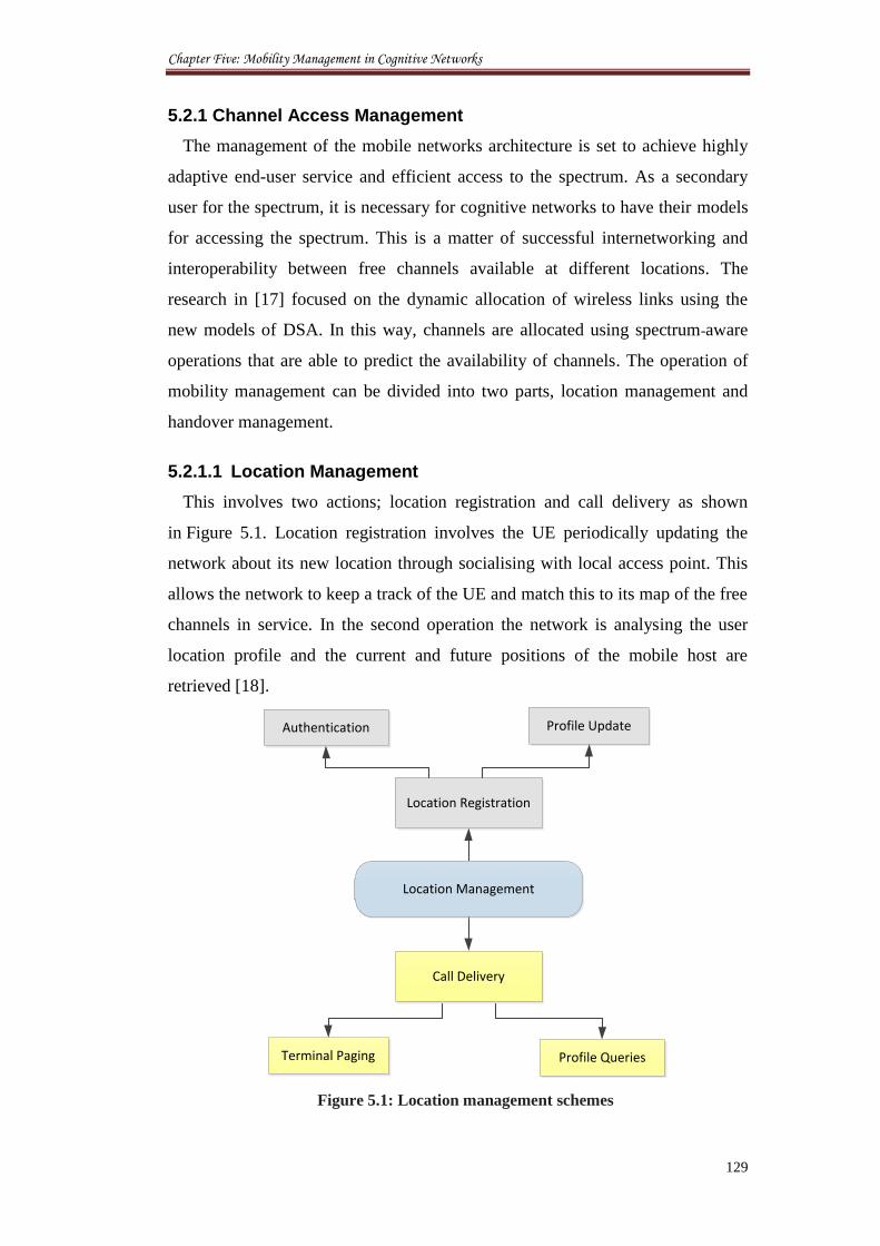
Chapter Five: Mobility Management in Cognitive Networks
129
5.2.1 Channel Access Management
The management of the mobile networks architecture is set to achieve highly
adaptive end-user service and efficient access to the spectrum. As a secondary
user for the spectrum, it is necessary for cognitive networks to have their models
for accessing the spectrum. This is a matter of successful internetworking and
interoperability between free channels available at different locations. The
research in [17] focused on the dynamic allocation of wireless links using the
new models of DSA. In this way, channels are allocated using spectrum-aware
operations that are able to predict the availability of channels. The operation of
mobility management can be divided into two parts, location management and
handover management.
5.2.1.1 Location Management
This involves two actions; location registration and call delivery as shown
in Figure 5.1. Location registration involves the UE periodically updating the
network about its new location through socialising with local access point. This
allows the network to keep a track of the UE and match this to its map of the free
channels in service. In the second operation the network is analysing the user
location profile and the current and future positions of the mobile host are
retrieved [18].
Location Registration
Call Delivery
Profile UpdateAuthentication
Terminal Paging Profile Queries
Location Management
Figure 5.1: Location management schemes
Chapter Five: Mobility Management in Cognitive Networks
130
The location of the mobile phone can be predicated if the trajectory of
movement has been set already. This could be a result of long/mid-term
monitoring of the mobile movement routes and times. In this way, the site’s
position is directly updated during regular data exchanges and socialisation with
the mobile unit. The mobile site’s x- and y-positions specify its location in its
parent sub-network. A mobile site’s altitude attribute specifies its elevation in
relative to sea level, the underlying terrain, or the parent sub-network. A change
to one of these attributes will cause an immediate change in the location of the
mobile site. Typically, there are two techniques employed to dynamically change
the location of a mobile site [19]:
Centralised approach, in which one process is responsible for updating
the positions of all of the mobile sites in a network model. Often this
method requires a central control site to which all locations updates are
directed.
Decentralised approach, in the sense that each mobile site has a
process executing within it that updates only its own position. The key
difference between a centralised management system and a
decentralised management system, is that the above runs a management
operation as a centralised process, while this runs as a distributed
process. This approach is more suitable to perform efficiently in large
networks such as our model for cognitive microcells. Also, this
approach is more flexible in dynamically adapting to network failures
and any other changes in state and network configuration.
5.2.1.2 Handover Management
Handover management is a fundamental operation for any mobile network.
Although its functionality and implementation differs among the various
technologies, some basic characteristics are common. Handover management
enables the network to keep active connections during mobile user movement or
even balance the network load evenly among different areas [20].
The operations of handover management are shown in Figure 5.2 and include
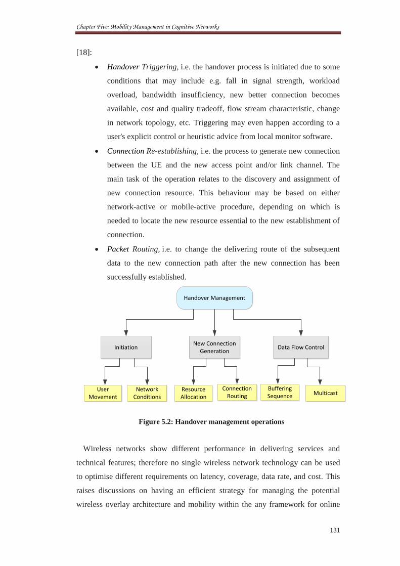
Chapter Five: Mobility Management in Cognitive Networks
131
[18]:
Handover Triggering, i.e. the handover process is initiated due to some
conditions that may include e.g. fall in signal strength, workload
overload, bandwidth insufficiency, new better connection becomes
available, cost and quality tradeoff, flow stream characteristic, change
in network topology, etc. Triggering may even happen according to a
user's explicit control or heuristic advice from local monitor software.
Connection Re-establishing, i.e. the process to generate new connection
between the UE and the new access point and/or link channel. The
main task of the operation relates to the discovery and assignment of
new connection resource. This behaviour may be based on either
network-active or mobile-active procedure, depending on which is
needed to locate the new resource essential to the new establishment of
connection.
Packet Routing, i.e. to change the delivering route of the subsequent
data to the new connection path after the new connection has been
successfully established.
Data Flow Control Initiation
User Movement
Network Conditions
Buffering Sequence Multicast
New Connection Generation
Resource Allocation
Connection Routing
Handover Management
Figure 5.2: Handover management operations
Wireless networks show different performance in delivering services and
technical features; therefore no single wireless network technology can be used
to optimise different requirements on latency, coverage, data rate, and cost. This
raises discussions on having an efficient strategy for managing the potential
wireless overlay architecture and mobility within the any framework for online
Chapter Five: Mobility Management in Cognitive Networks
132
communications. In homogeneous networks, traditional horizontal handover can
be employed for intra-technology mobility. In heterogeneous networks, vertical
handover should be used for inter-technology mobility. Vertical handover may
occur either upward (i.e. to a larger cell size and lower bandwidth) or downward
(i.e. to a smaller cell size and higher bandwidth); and the UE does not necessarily
move out of the coverage area of the original cell. Some packet-level QoS
parameters become more important to real-time multimedia services, including
packet latency, packet loss rate, throughput, signalling bandwidth overhead, and
device power consumption [21, 22].
5.2.2 Handover in Cognitive Networks
The main reason for this intensive interest in handover over cognitive networks
is that there is no concise description for the changes that cognitive radio would
bring to the current mesh networks. This problem is growing with the absence of
a standard cognitive radio system definition. For example, the cognitive radio
suggested by [23] can adapt its transmission signals to efficiently utilise and
respond to the spectrum changes. Therefore, cognitive mesh networks face many
serious challenges in order to establish successful online communication links.
One of these challenges is that CMNs has many cell nodes that need to be
connected wirelessly together during the establishment of any link. This means
that a high numbers of handovers are likely to occur in certain cognitive node
due to the primary users’ activities. Such a situation can block success of the
future CMN in achieving real time communications between subscribers. In
addition, it raises many questions about the expected numbers of handovers in
such a network. The setback factors in CMN can result also from the absence of
any guarantee for stability of wireless links in a dynamic wireless spectrum
access models. Hence, cognitive wireless links can be interrupted at any time due
to the transmissions of the primary networks. In this way, the more interrupted
cognitive services, the less time online for cognitive communications and more
handovers iterations occurrence. These bring forward the challenge of reducing
the spectrum handover while reducing the complexity of running such networks.
Besides the basic functions of handover management, there are additional
requirements for performance and packet-level QoS that should be taken into
account when trying to design a new handover management scheme, including
Chapter Five: Mobility Management in Cognitive Networks
133
[18 - 20]:
Fast Handover, i.e. this ensures that UE can receive data packets at its
new location/channel within a reasonable time interval (at certain time
counter) in order to reduce the packet delay as much as possible. This is
extremely important in real-time services.
Seamless Handover, i.e. any handover algorithm should minimise the
packet loss rate into zero or near zero.
Routing Efficiency, i.e. the routing path between corresponding access
point and MU should be optimised in order to exclude possible
redundant transfer. This is proposed to be performed by the CRoF-core
management unit.
Therefore, it is necessary to analyse the expected free resources in different
areas prior to any domain-based mobility management actions. This allows
deciding the mobile handover that could happen within one domain or between
different domains. This future analysis for spectrum usage is known as the
Spectrum Forecasting.
5.2.3 Spectrum Forecasting
Spectrum Forecasting is an emerging topic for the 4G networks. This expectation
for spectrum availability resulted from spatio long-term monitoring of the
spectrum usage. Initially, these analyses motivated the development of the
cognitive radio, and it may also motivate the selection criteria for CMN
installation positions. The measurement of channels availability as a function of
time and place may lead to a new category of spectrum forecasting namely:
Global and Local Spectrum Forecasting.
For global forecasting, the charts for spectrum channels availability can be
produced by the main spectrum governing entities, such as the FCC and the
Ofcom. This is supported by the fact that these institutes have all information
about the spectrum users’ licenses and the occurrence time of their activities.
The spectrum management entities are likely to monitor the licensed users to
assess the possibility to offering licensed channels to cognitive services. In this
way, spectrum reports may be generated on hourly, daily and annually basis in
Chapter Five: Mobility Management in Cognitive Networks
134
order to be used to predict future spectrum usage. These reports and expectations
cover big cities and wide sites of the states at overlay networks services.
The other kind of spectrum forecasting is the local determination for the
available resources. Here, the free spectrum holes are tracked for small sized cell
and sub-cell domains where some channels could be accessible in some areas but
they are not in others. Obviously, these measurements can be done by local
cognitive radio units. Therefore, efficient sensing, and the collaborative
distribution of sensing data are crucial for obtaining comprehensive spectrum
usage reports. Actually, there are two main challenges in this kind of spectrum
assessment:
Firstly, new sensing schemes should be developed to intelligently track
the free channel spaces and also the angle of arrival. This leads to slice
the coverage domains and help to solve the problem of the hidden
point.
Secondly, local spectrum management entities role emerge to distribute
the obtained spectrum reports between local users. The proposals for
Local Spectrum Brokers find a strong inspiration for implementation
here where the broker can contact all users in its area. However, the
question here is how to accomplish the necessary awareness to analyse
these data on a real time basis. Then, how to assign the requested
evaluations to certain users? In fact, all these dynamic computational
and geographical data will increase considerably the complexity of the
cognitive network.
The spectrum forecasting reports are delivered to the cognitive nodes
according to the level they intend to access in the spectrum. Therefore, global
reports are provided if a link establishment is needed over multi-cell hops. While,
local reports would be provided for users at intracell domains. The other scenario
suggests that both reports are provided to all stations, and hence, a wireless link
can be created from many short connections using local channels. This is the
most useful setup, especially in a very dynamic wireless environment with an
increasing number of cognitive users.
Chapter Five: Mobility Management in Cognitive Networks
135
5.3 IP Modelling
Research and technological development on handovers in macrocell network
has been going extensively to provide better Radio Resource Management
(RRM). Most of the researches focused on network-controlled horizontal
handover where handover is executed between adjacent cells of the same
network. In order to achieve the optimise procedure, a new handover decision
policy based on mobility prediction is introduced and proposed to mitigate the
frequent and unnecessary handover. This is based on IP wireless network where
handover is done typically in LTE networks. The development in both L1
(physical layer) and L2 (MAC layer) is undergoing in order to realise the most
efficient handover and reduce the handover overhead [24].
Mobile IPv6 (MIPv6) [5] has been proposed by Internet Engineering Task
Force (IETF) to support mobility for nodes in IPv6 networks. Though MIPv6
proposes many solutions to provide mobility, it also poses many challenges to
the network world, mainly delay, packet loss and signalling overhead caused
during the movement of the node. These factors result in the disturbance or
disconnection of real-time applications such as Voice over Internet Protocol
(VoIP). When a UE changes its point of attachment, the node moves from one
network to another; this process is called a handoff or handover. Handover
latency is one factor that makes most mobility protocols lose sessions during
movement. Many Transmission Control Protocol (TCP) [6] applications can
request retransmission in case of loss of packets, but real-time applications
cannot do so because they rely mostly on User Datagram Protocol (UDP) [7]
transmission. Real-time applications are time sensitive and rely on timely
controlled packets that cannot be recovered once lost during the handover
process. Many methods have been proposed by researchers to solve handoff
latency problems, which include reduction in movement detection [8], packet
loss [9], creating new IPv6 address, exchanging fast signals between old
networks and performing fast signalling [10] in the new network. An extension
to the MIPv6 original protocol called Fast Handover in MIPv6 (FMIPv6) [11]
and Hierarchical Mobile IPv6 [12] has also been standardized to reduce the
handoff latency. This section identifies the new IP integrated model for the LTE
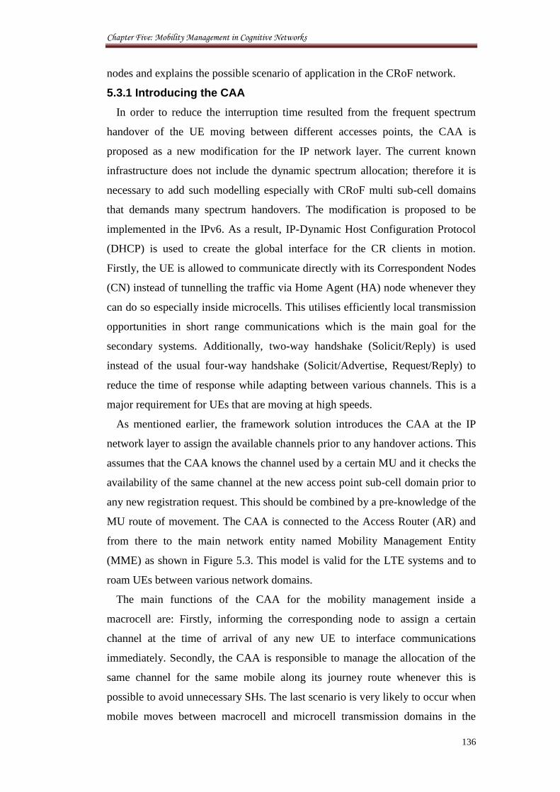
Chapter Five: Mobility Management in Cognitive Networks
136
nodes and explains the possible scenario of application in the CRoF network.
5.3.1 Introducing the CAA
In order to reduce the interruption time resulted from the frequent spectrum
handover of the UE moving between different accesses points, the CAA is
proposed as a new modification for the IP network layer. The current known
infrastructure does not include the dynamic spectrum allocation; therefore it is
necessary to add such modelling especially with CRoF multi sub-cell domains
that demands many spectrum handovers. The modification is proposed to be
implemented in the IPv6. As a result, IP-Dynamic Host Configuration Protocol
(DHCP) is used to create the global interface for the CR clients in motion.
Firstly, the UE is allowed to communicate directly with its Correspondent Nodes
(CN) instead of tunnelling the traffic via Home Agent (HA) node whenever they
can do so especially inside microcells. This utilises efficiently local transmission
opportunities in short range communications which is the main goal for the
secondary systems. Additionally, two-way handshake (Solicit/Reply) is used
instead of the usual four-way handshake (Solicit/Advertise, Request/Reply) to
reduce the time of response while adapting between various channels. This is a
major requirement for UEs that are moving at high speeds.
As mentioned earlier, the framework solution introduces the CAA at the IP
network layer to assign the available channels prior to any handover actions. This
assumes that the CAA knows the channel used by a certain MU and it checks the
availability of the same channel at the new access point sub-cell domain prior to
any new registration request. This should be combined by a pre-knowledge of the
MU route of movement. The CAA is connected to the Access Router (AR) and
from there to the main network entity named Mobility Management Entity
(MME) as shown in Figure 5.3. This model is valid for the LTE systems and to
roam UEs between various network domains.
The main functions of the CAA for the mobility management inside a
macrocell are: Firstly, informing the corresponding node to assign a certain
channel at the time of arrival of any new UE to interface communications
immediately. Secondly, the CAA is responsible to manage the allocation of the
same channel for the same mobile along its journey route whenever this is
possible to avoid unnecessary SHs. The last scenario is very likely to occur when
mobile moves between macrocell and microcell transmission domains in the
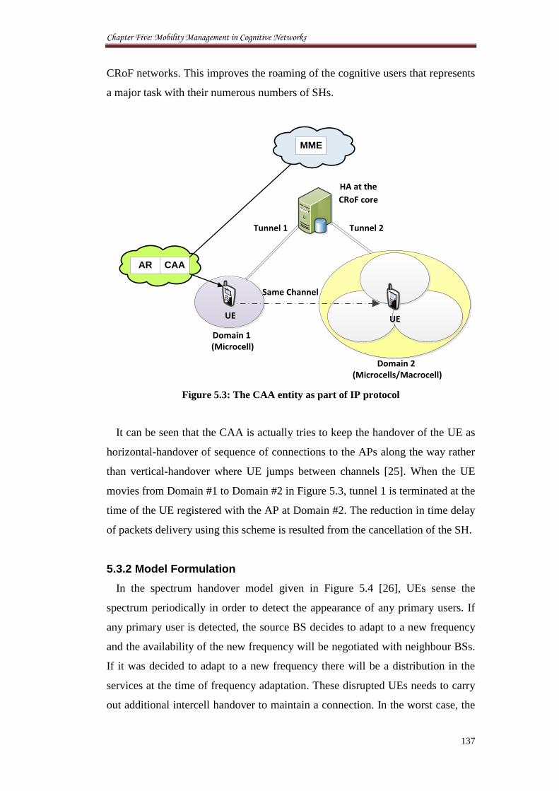
Chapter Five: Mobility Management in Cognitive Networks
137
CRoF networks. This improves the roaming of the cognitive users that represents
a major task with their numerous numbers of SHs.
Domain 1 (Microcell)
UEUE
Domain 2 (Microcells/Macrocell)
Tunnel 1
Tunnel 2
UEUE
HA at the
CRoF core
CAA
MME
AR
Same Channel
Figure 5.3: The CAA entity as part of IP protocol
It can be seen that the CAA is actually tries to keep the handover of the UE as
horizontal-handover of sequence of connections to the APs along the way rather
than vertical-handover where UE jumps between channels [25]. When the UE
movies from Domain #1 to Domain #2 in Figure 5.3, tunnel 1 is terminated at the
time of the UE registered with the AP at Domain #2. The reduction in time delay
of packets delivery using this scheme is resulted from the cancellation of the SH.
5.3.2 Model Formulation
In the spectrum handover model given in Figure 5.4 [26], UEs sense the
spectrum periodically in order to detect the appearance of any primary users. If
any primary user is detected, the source BS decides to adapt to a new frequency
and the availability of the new frequency will be negotiated with neighbour BSs.
If it was decided to adapt to a new frequency there will be a distribution in the
services at the time of frequency adaptation. These disrupted UEs needs to carry
out additional intercell handover to maintain a connection. In the worst case, the
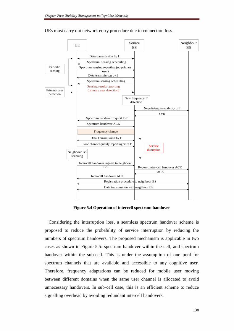
Chapter Five: Mobility Management in Cognitive Networks
138
UEs must carry out network entry procedure due to connection loss.
UESource
BS
Neighbour
BS
Data transmission by f
Spectrum sensing scheduling
Spectrum sensing reporting (no primary
user)
Data transmission by f
Sensing results reporting
(primary user detection)
Negotiating availability of f’
Spectrum handover request to f’
Poor channel quality reporting with f’
Spectrum sensing scheduling
New frequency f’
detection
ACK
Spectrum handover ACK
Frequency change
Data Transmission by f’
Service
disruptionNeighbour BS
scanning
Inter-cell handover request to neighbour
BS Request inter-cell handover ACK
ACK
Inter-cell handover ACK
Registration procedure to neighbour BS
Data transmission with neighbour BS
Periodic
sensing
Primary user
detection
Figure 5.4 Operation of intercell spectrum handover
Considering the interruption loss, a seamless spectrum handover scheme is
proposed to reduce the probability of service interruption by reducing the
numbers of spectrum handovers. The proposed mechanism is applicable in two
cases as shown in Figure 5.5: spectrum handover within the cell, and spectrum
handover within the sub-cell. This is under the assumption of one pool for
spectrum channels that are available and accessible to any cognitive user.
Therefore, frequency adaptations can be reduced for mobile user moving
between different domains when the same user channel is allocated to avoid
unnecessary handovers. In sub-cell case, this is an efficient scheme to reduce
signalling overhead by avoiding redundant intercell handovers.
Chapter Five: Mobility Management in Cognitive Networks
139
Cognitive
Microcell
Cognitive
Macrocell
Channel
Band #1
Channel
Band #2
Channel
Pool
Intercell Handover
(cell case)
Cognitive
Microcell
Ch#1
Ch#2
Intracell Handover
(sub-cell case)
Figure 5.5: Inter/Intra cell spectrum handover
Using the proposed spectrum handover scheme, an intercell handover can be
enforced before changing the frequency in case that same frequency channel is
not available. In addition, the suspension of the intercell handover of a UE at the
edge of a cell can be enforced to reduce signalling overhead if UE has changed
his course of movement backwards or if the same channel can be secured to the
UE in the new domain. Then, two conditions are defined in related to spectrum
handover: the enforcing condition of spectrum handover and the stopping
condition of spectrum handover.
Condition 1: Enforcing spectrum handover:
{ ( ) } { ( ) } ( )
Condition 2: Stopping of spectrum handover:
{ ( ) } { ( ) } ( )
where is the original frequency of serving BS, is the new frequency of the
serving BS after spectrum handover, is the frequency of the next BS indexed
by , is the threshold for triggering spectrum handover, is the threshold
for determining spectrum handover, and is defined as the received SINR for
each frequency.
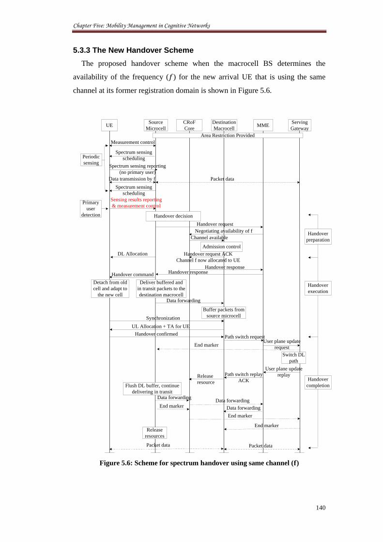
Chapter Five: Mobility Management in Cognitive Networks
140
5.3.3 The New Handover Scheme
The proposed handover scheme when the macrocell BS determines the
availability of the frequency ( ) for the new arrival UE that is using the same
channel at its former registration domain is shown in Figure 5.6.
UESource
Microcell
Destination
Macrocell
Measurement control
Spectrum sensing reporting
(no primary user)
Data transmission by f
Sensing results reporting
& measurement control
Negotiating availability of f
Handover command
Spectrum sensing
schedulingPeriodic
sensing
Primary
user
detection
Handover request ACK
Channel f now allocated to UE
Handover confirmed
MMEServing
Gateway
Admission control
Handover request
Path switch requestUser plane update
request
Switch DL
path
Detach from old
cell and adapt to
the new cell
Deliver buffered and
in transit packets to the
destination macrocellData forwarding
End marker
Path switch replay
ACKFlush DL buffer, continue
delivering in transit Data forwarding
End marker
Release
resources
Packet dataPacket data
Handover
preparation
Handover
execution
Spectrum sensing
scheduling
Handover
completion
CRoF
Core
Handover decision
Buffer packets from
source microcell
User plane update
replayRelease
resource
Data forwarding
End marker
End marker
Data forwarding
DL Allocation
Channel available
Handover response
Synchronization
UL Allocation + TA for UE
Handover response
Area Restriction Provided
Packet data
Figure 5.6: Scheme for spectrum handover using same channel ( )
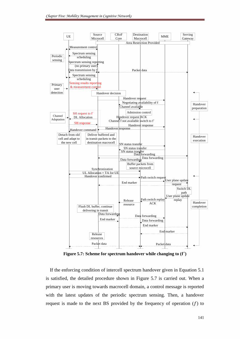
Chapter Five: Mobility Management in Cognitive Networks
141
UESource
Microcell
Destination
Macrocell
Measurement control
Spectrum sensing reporting
(no primary user)
Data transmission by f
Sensing results reporting
& measurement control
Negotiating availability of f
Handover command
Spectrum sensing
schedulingPeriodic
sensing
Primary
user
detection
Handover request ACK
Channel f not available switch to f`
Handover confirmed
MMEServing
Gateway
Admission control
Handover request
Path switch requestUser plane update
request
Switch DL
path
Detach from old
cell and adapt to
the new cell
Deliver buffered and
in transit packets to the
destination macrocell
Data forwarding
End marker
Path switch replay
ACKFlush DL buffer, continue
delivering in transit Data forwarding
End marker
Release
resources
Packet dataPacket data
Handover
preparation
Handover
execution
Spectrum sensing
scheduling
Handover
completion
CRoF
Core
Handover decision
Buffer packets from
source microcell
User plane update
replayRelease
resource
Data forwarding
End marker
End marker
Data forwarding
SH request to f`
DL Allocation
Channel available
Handover response
Synchronization
UL Allocation + TA for UE
Handover response
Area Restriction Provided
SH response
Channel
Adaptation
Data forwarding Data forwarding
SN status transfer
SN status transferSN status transfer
Packet data
Figure 5.7: Scheme for spectrum handover while changing to ( )
If the enforcing condition of intercell spectrum handover given in Equation 5.1
is satisfied, the detailed procedure shown in Figure 5.7 is carried out. When a
primary user is moving towards macrocell domain, a control message is reported
with the latest updates of the periodic spectrum sensing. Then, a handover
request is made to the next BS provided by the frequency of operation ( ) to
Chapter Five: Mobility Management in Cognitive Networks
142
negotiate the availability of this channel at the new domain. Then, if the
frequency is not available at the new destination BS, a channel scanning is
performed to look for a new available channel namely ( ). Then a channel
adaption request is sent back to the UE to change to ( ). Here and before
changing the frequency, the UE buffer the data and halt transmission while
packets at the microcell are also buffered and directed to the macrocell BS. When
the BS adapts to a new frequency, all the other transmission conditions are
maintained except the centre frequency. A path switch request is issued to the
CRoF core that acts as the serving gateway and the user plane profile is updated
with the new location and frequency. In the proposed scheme, some UEs that
satisfy the enforcing condition of intercell handover may not immediately change
to a new frequency due to the limitation of resources available and the time
required for performing spectrum scanning and assigning new channels.
The handover scheme when the macrocell BS determines the availability of the
frequency ( ) for the new arrival UE is shown in Figure 5.7. It can be seen
clearly the differences in time spent while adapting the frequency between the
two scenarios of Figures 5.6 and 5.7. In the next section we will show the
installation scheme for the CAA functioning channel holding between various
BSs.
5.4 Spectrum Handover Mechanism
5.4.1 Channel Availability Algorithm
When the cognitive user issues a request for handover, it sends its location data
and its current used frequency channel. These are typed into the packets
attributes exchanged with the BS during the handover process. The MME starts
making predictions of the channel availability before the current transmission
frame ends. Based on the prediction, the MME decides whether to allocate the
same channel to the UE or to allocate a new channel or stop the ongoing
transmission. This model is proposing two conditions for determining whether a
spectrum handover should occur: (1) the forecast probability that the current
candidate channel (i.e., a channel that can be selected for continuing the current
data transmission) is busy or idle and (2) the expected length of the channel idle
period. Based on these measures, spectrum handover actions are performed as
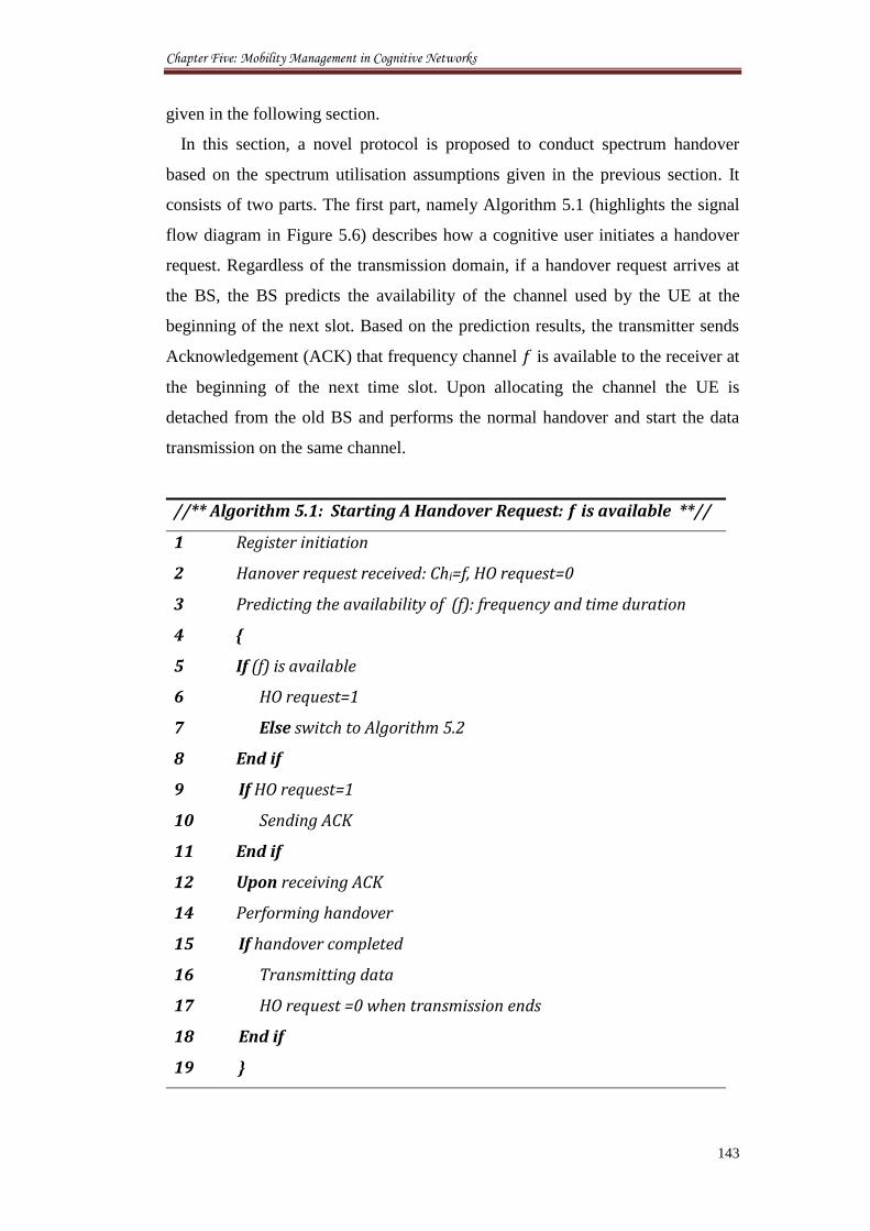
Chapter Five: Mobility Management in Cognitive Networks
143
given in the following section.
In this section, a novel protocol is proposed to conduct spectrum handover
based on the spectrum utilisation assumptions given in the previous section. It
consists of two parts. The first part, namely Algorithm 5.1 (highlights the signal
flow diagram in Figure 5.6) describes how a cognitive user initiates a handover
request. Regardless of the transmission domain, if a handover request arrives at
the BS, the BS predicts the availability of the channel used by the UE at the
beginning of the next slot. Based on the prediction results, the transmitter sends
Acknowledgement (ACK) that frequency channel is available to the receiver at
the beginning of the next time slot. Upon allocating the channel the UE is
detached from the old BS and performs the normal handover and start the data
transmission on the same channel.
//** Algorithm 5.1: Starting A Handover Request: is available **//
1 Register initiation
2 Hanover request received: Chi=f, HO request=0
3 Predicting the availability of (f): frequency and time duration
4 {
5 If (f) is available
6 HO request=1
7 Else switch to Algorithm 5.2
8 End if
9 If HO request=1
10 Sending ACK
11 End if
12 Upon receiving ACK
14 Performing handover
15 If handover completed
16 Transmitting data
17 HO request =0 when transmission ends
18 End if
19 }
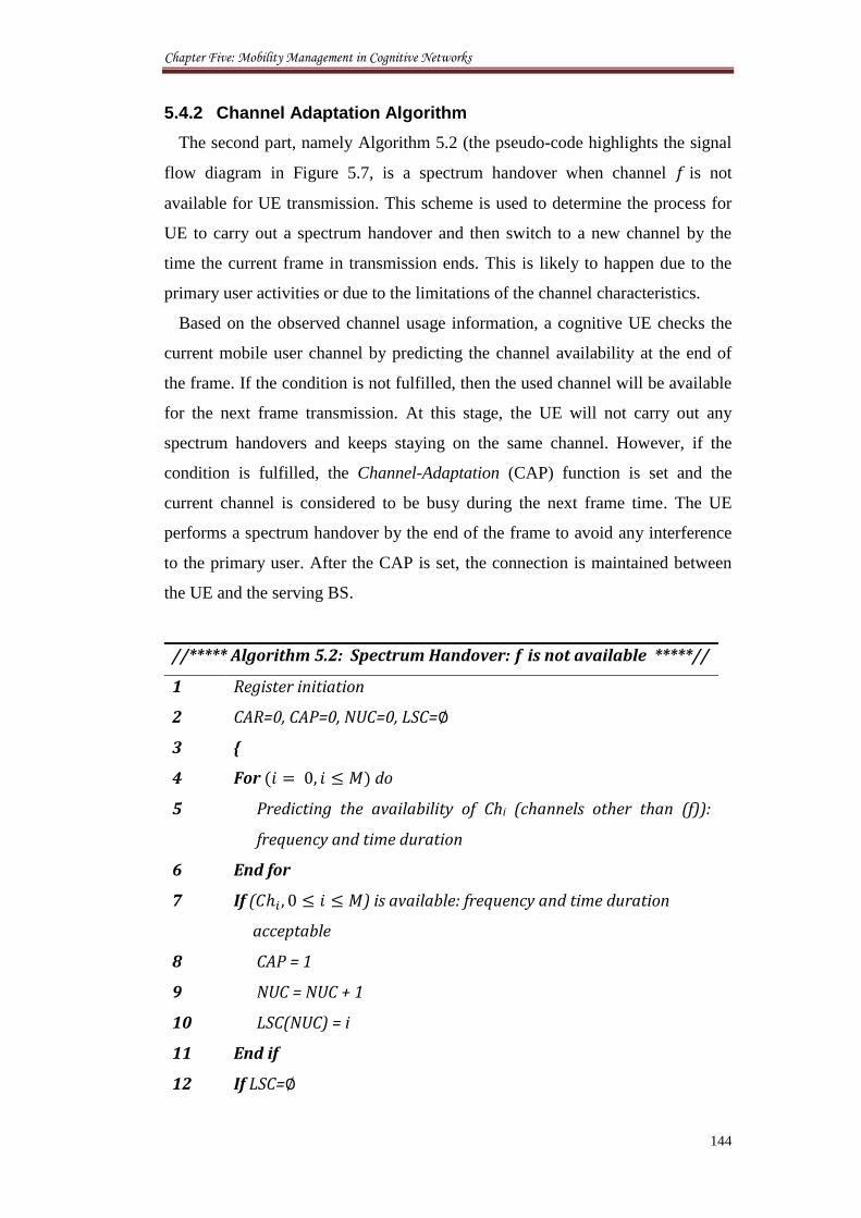
Chapter Five: Mobility Management in Cognitive Networks
144
5.4.2 Channel Adaptation Algorithm
The second part, namely Algorithm 5.2 (the pseudo-code highlights the signal
flow diagram in Figure 5.7, is a spectrum handover when channel is not
available for UE transmission. This scheme is used to determine the process for
UE to carry out a spectrum handover and then switch to a new channel by the
time the current frame in transmission ends. This is likely to happen due to the
primary user activities or due to the limitations of the channel characteristics.
Based on the observed channel usage information, a cognitive UE checks the
current mobile user channel by predicting the channel availability at the end of
the frame. If the condition is not fulfilled, then the used channel will be available
for the next frame transmission. At this stage, the UE will not carry out any
spectrum handovers and keeps staying on the same channel. However, if the
condition is fulfilled, the Channel-Adaptation (CAP) function is set and the
current channel is considered to be busy during the next frame time. The UE
performs a spectrum handover by the end of the frame to avoid any interference
to the primary user. After the CAP is set, the connection is maintained between
the UE and the serving BS.
//***** Algorithm 5.2: Spectrum Handover: is not available *****//
1 Register initiation
2 CAR=0, CAP=0, NUC=0, LSC=
3 {
4 For ( ) do
5 Predicting the availability of Chi (channels other than (f)):
frequency and time duration
6 End for
7 If ( ) is available: frequency and time duration
acceptable
8 CAP = 1
9 NUC = NUC + 1
10 LSC(NUC) = i
11 End if
12 If LSC=
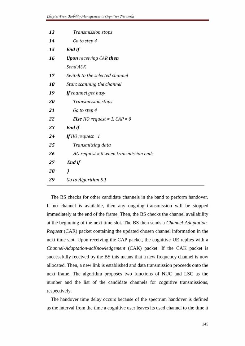
Chapter Five: Mobility Management in Cognitive Networks
145
13 Transmission stops
14 Go to step 4
15 End if
16 Upon receiving CAR then
Send ACK
17 Switch to the selected channel
18 Start scanning the channel
19 If channel get busy
20 Transmission stops
21 Go to step 4
22 Else HO request = 1, CAP = 0
23 End if
24 If HO request =1
25 Transmitting data
26 HO request = 0 when transmission ends
27 End if
28 }
29 Go to Algorithm 5.1
The BS checks for other candidate channels in the band to perform handover.
If no channel is available, then any ongoing transmission will be stopped
immediately at the end of the frame. Then, the BS checks the channel availability
at the beginning of the next time slot. The BS then sends a Channel-Adaptation-
Request (CAR) packet containing the updated chosen channel information in the
next time slot. Upon receiving the CAP packet, the cognitive UE replies with a
Channel-Adaptation-acKnowledgement (CAK) packet. If the CAK packet is
successfully received by the BS this means that a new frequency channel is now
allocated. Then, a new link is established and data transmission proceeds onto the
next frame. The algorithm proposes two functions of NUC and LSC as the
number and the list of the candidate channels for cognitive transmissions,
respectively.
The handover time delay occurs because of the spectrum handover is defined
as the interval from the time a cognitive user leaves its used channel to the time it
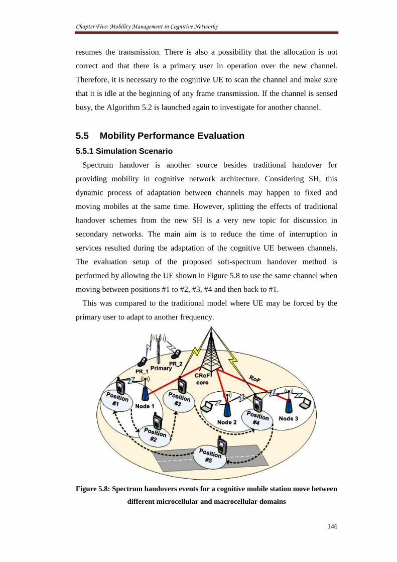
Chapter Five: Mobility Management in Cognitive Networks
146
resumes the transmission. There is also a possibility that the allocation is not
correct and that there is a primary user in operation over the new channel.
Therefore, it is necessary to the cognitive UE to scan the channel and make sure
that it is idle at the beginning of any frame transmission. If the channel is sensed
busy, the Algorithm 5.2 is launched again to investigate for another channel.
5.5 Mobility Performance Evaluation
5.5.1 Simulation Scenario
Spectrum handover is another source besides traditional handover for
providing mobility in cognitive network architecture. Considering SH, this
dynamic process of adaptation between channels may happen to fixed and
moving mobiles at the same time. However, splitting the effects of traditional
handover schemes from the new SH is a very new topic for discussion in
secondary networks. The main aim is to reduce the time of interruption in
services resulted during the adaptation of the cognitive UE between channels.
The evaluation setup of the proposed soft-spectrum handover method is
performed by allowing the UE shown in Figure 5.8 to use the same channel when
moving between positions #1 to #2, #3, #4 and then back to #1.
This was compared to the traditional model where UE may be forced by the
primary user to adapt to another frequency.
Figure 5.8: Spectrum handovers events for a cognitive mobile station move between
different microcellular and macrocellular domains
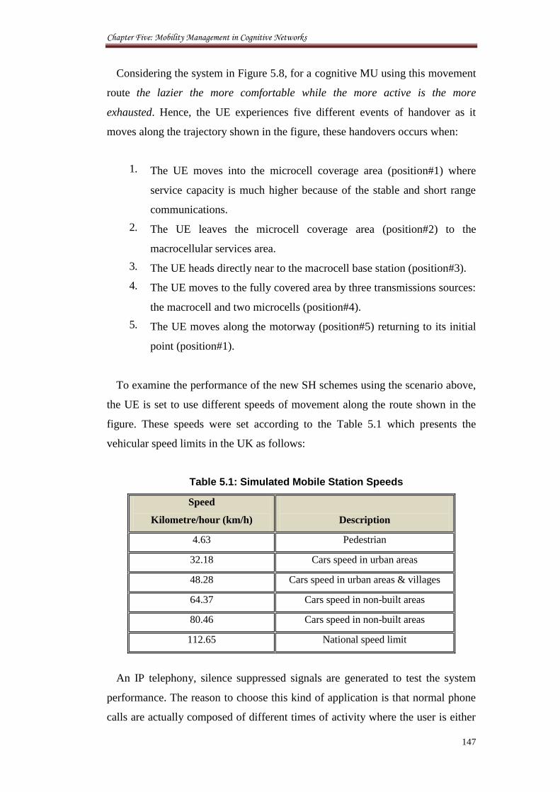
Chapter Five: Mobility Management in Cognitive Networks
147
Considering the system in Figure 5.8, for a cognitive MU using this movement
route the lazier the more comfortable while the more active is the more
exhausted. Hence, the UE experiences five different events of handover as it
moves along the trajectory shown in the figure, these handovers occurs when:
1. The UE moves into the microcell coverage area (position#1) where
service capacity is much higher because of the stable and short range
communications.
2. The UE leaves the microcell coverage area (position#2) to the
macrocellular services area.
3. The UE heads directly near to the macrocell base station (position#3).
4. The UE moves to the fully covered area by three transmissions sources:
the macrocell and two microcells (position#4).
5. The UE moves along the motorway (position#5) returning to its initial
point (position#1).
To examine the performance of the new SH schemes using the scenario above,
the UE is set to use different speeds of movement along the route shown in the
figure. These speeds were set according to the Table 5.1 which presents the
vehicular speed limits in the UK as follows:
Table 5.1: Simulated Mobile Station Speeds
Speed
Kilometre/hour (km/h)
Description
4.63 Pedestrian
32.18 Cars speed in urban areas
48.28 Cars speed in urban areas & villages
64.37 Cars speed in non-built areas
80.46 Cars speed in non-built areas
112.65 National speed limit
An IP telephony, silence suppressed signals are generated to test the system
performance. The reason to choose this kind of application is that normal phone
calls are actually composed of different times of activity where the user is either
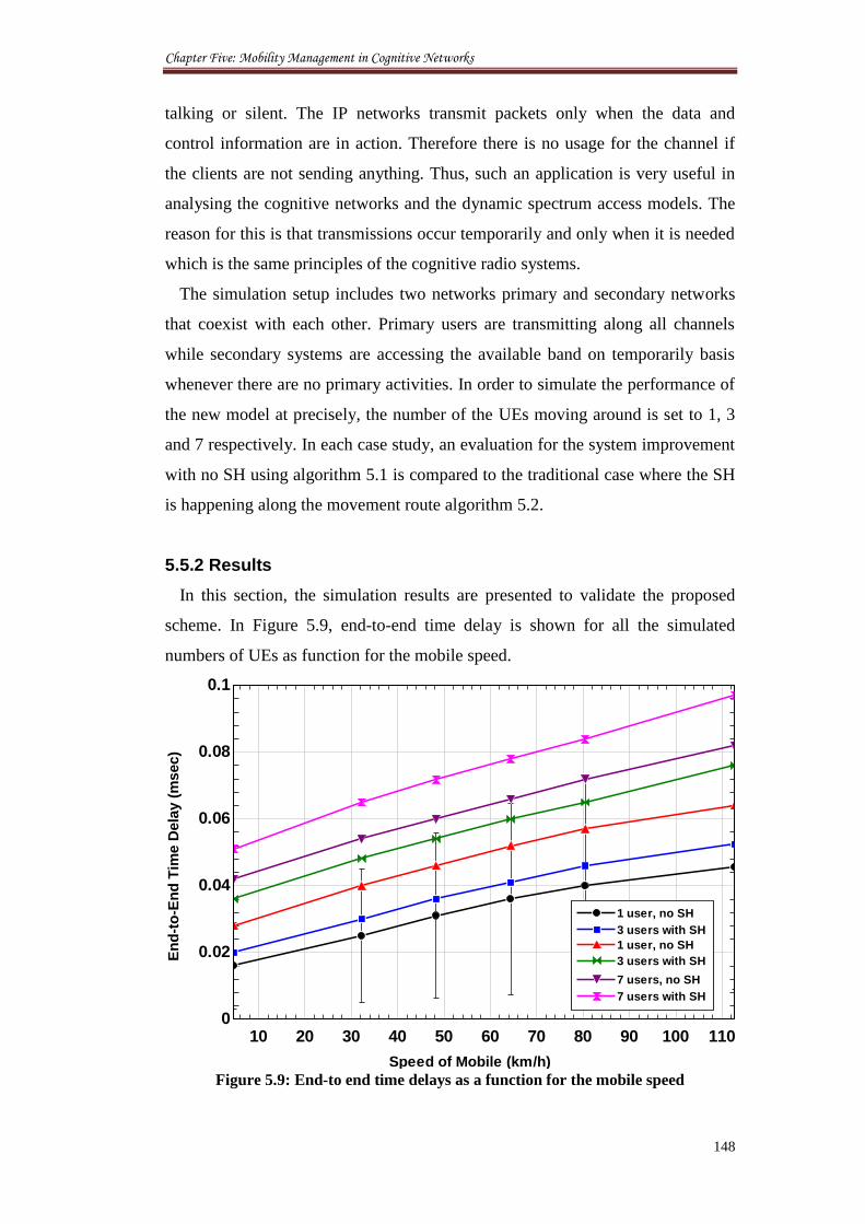
Chapter Five: Mobility Management in Cognitive Networks
148
talking or silent. The IP networks transmit packets only when the data and
control information are in action. Therefore there is no usage for the channel if
the clients are not sending anything. Thus, such an application is very useful in
analysing the cognitive networks and the dynamic spectrum access models. The
reason for this is that transmissions occur temporarily and only when it is needed
which is the same principles of the cognitive radio systems.
The simulation setup includes two networks primary and secondary networks
that coexist with each other. Primary users are transmitting along all channels
while secondary systems are accessing the available band on temporarily basis
whenever there are no primary activities. In order to simulate the performance of
the new model at precisely, the number of the UEs moving around is set to 1, 3
and 7 respectively. In each case study, an evaluation for the system improvement
with no SH using algorithm 5.1 is compared to the traditional case where the SH
is happening along the movement route algorithm 5.2.
5.5.2 Results
In this section, the simulation results are presented to validate the proposed
scheme. In Figure 5.9, end-to-end time delay is shown for all the simulated
numbers of UEs as function for the mobile speed.
Figure 5.9: End-to end time delays as a function for the mobile speed
10 20 30 40 50 60 70 80 90 100 1100
0.02
0.04
0.06
0.08
0.1
1 user, no SH1 user, no SH
3 users with SH3 users with SH
1 user, no SH1 user, no SH
3 users with SH3 users with SH
7 users, no SH7 users, no SH
7 users with SH7 users with SH
En
d-t
o-E
nd
Tim
e D
ela
y (
msec)
Speed of Mobile (km/h)
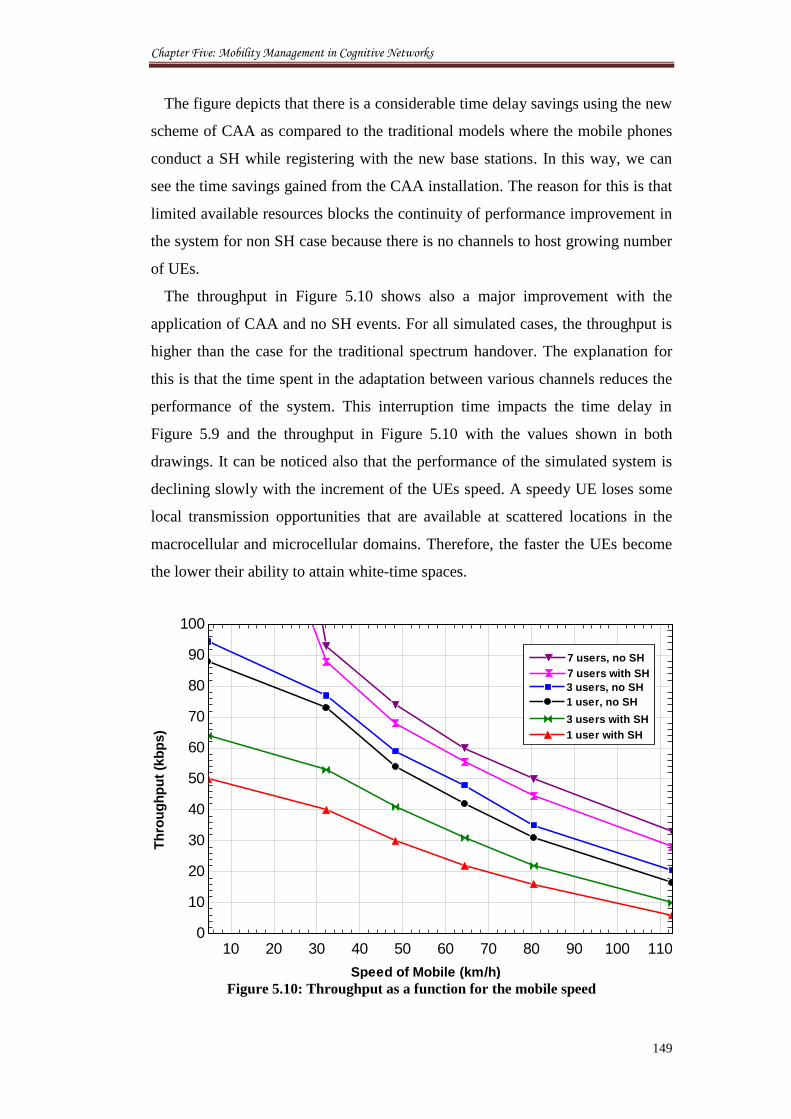
Chapter Five: Mobility Management in Cognitive Networks
149
The figure depicts that there is a considerable time delay savings using the new
scheme of CAA as compared to the traditional models where the mobile phones
conduct a SH while registering with the new base stations. In this way, we can
see the time savings gained from the CAA installation. The reason for this is that
limited available resources blocks the continuity of performance improvement in
the system for non SH case because there is no channels to host growing number
of UEs.
The throughput in Figure 5.10 shows also a major improvement with the
application of CAA and no SH events. For all simulated cases, the throughput is
higher than the case for the traditional spectrum handover. The explanation for
this is that the time spent in the adaptation between various channels reduces the
performance of the system. This interruption time impacts the time delay in
Figure 5.9 and the throughput in Figure 5.10 with the values shown in both
drawings. It can be noticed also that the performance of the simulated system is
declining slowly with the increment of the UEs speed. A speedy UE loses some
local transmission opportunities that are available at scattered locations in the
macrocellular and microcellular domains. Therefore, the faster the UEs become
the lower their ability to attain white-time spaces.
Figure 5.10: Throughput as a function for the mobile speed
10 20 30 40 50 60 70 80 90 100 1100
10
20
30
40
50
60
70
80
90
100
Th
rou
gh
pu
t (k
bp
s)
Speed of Mobile (km/h)
7 users, no SH7 users, no SH
7 users with SH7 users with SH
3 users, no SH3 users, no SH
1 user, no SH1 user, no SH
3 users with SH3 users with SH
1 user with SH1 user with SH
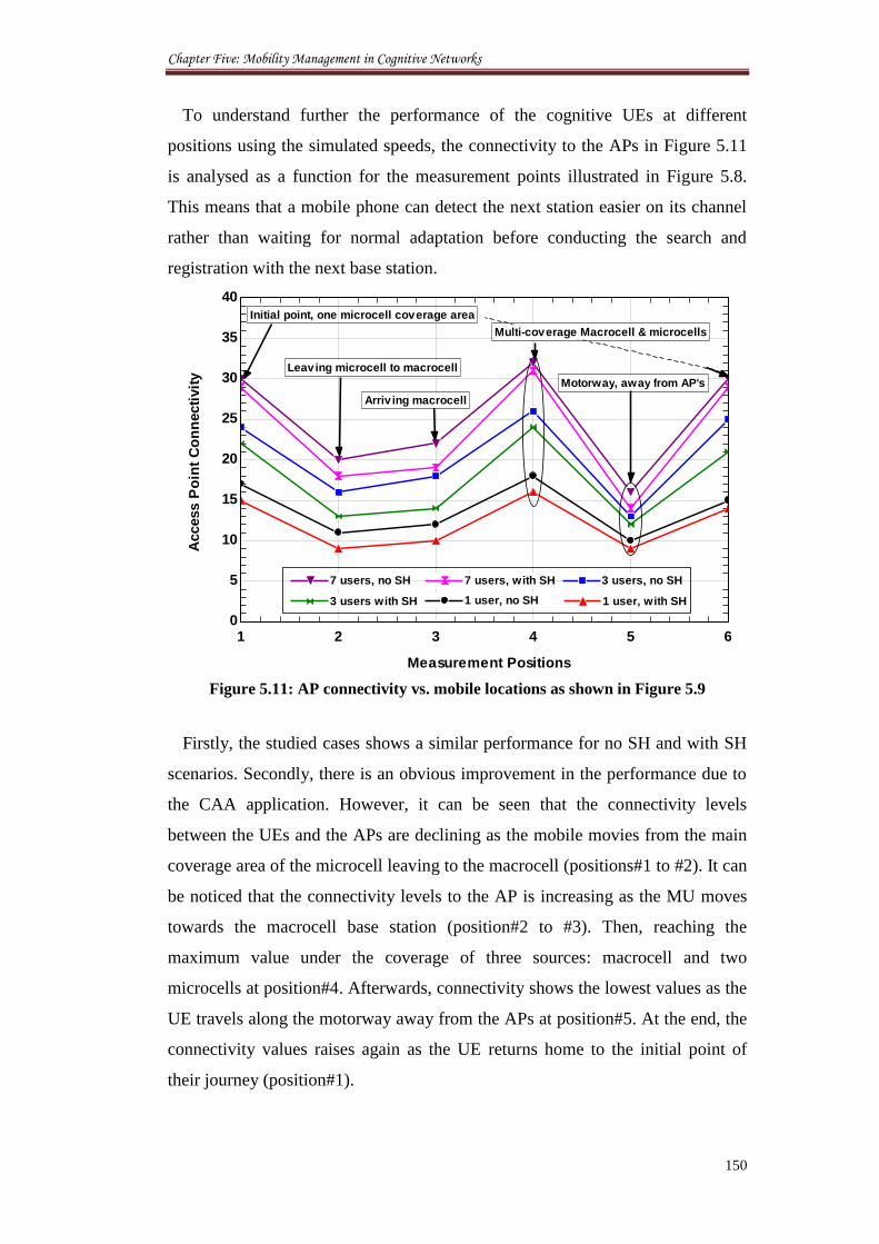
Chapter Five: Mobility Management in Cognitive Networks
150
To understand further the performance of the cognitive UEs at different
positions using the simulated speeds, the connectivity to the APs in Figure 5.11
is analysed as a function for the measurement points illustrated in Figure 5.8.
This means that a mobile phone can detect the next station easier on its channel
rather than waiting for normal adaptation before conducting the search and
registration with the next base station.
Figure 5.11: AP connectivity vs. mobile locations as shown in Figure 5.9
Firstly, the studied cases shows a similar performance for no SH and with SH
scenarios. Secondly, there is an obvious improvement in the performance due to
the CAA application. However, it can be seen that the connectivity levels
between the UEs and the APs are declining as the mobile movies from the main
coverage area of the microcell leaving to the macrocell (positions#1 to #2). It can
be noticed that the connectivity levels to the AP is increasing as the MU moves
towards the macrocell base station (position#2 to #3). Then, reaching the
maximum value under the coverage of three sources: macrocell and two
microcells at position#4. Afterwards, connectivity shows the lowest values as the
UE travels along the motorway away from the APs at position#5. At the end, the
connectivity values raises again as the UE returns home to the initial point of
their journey (position#1).
1 2 3 4 5 60
5
10
15
20
25
30
35
40
Measurement Positions
Access P
oin
t C
on
necti
vit
y
Initial point, one microcell coverage area
Multi-coverage Macrocell & microcells
Motorway, away from AP's
Leaving microcell to macrocell
Arriv ing macrocell
7 users, no SH7 users, no SH 7 users, with SH7 users, with SH 3 users, no SH3 users, no SH
3 users with SH3 users with SH 1 user, no SH1 user, no SH 1 user, with SH1 user, with SH
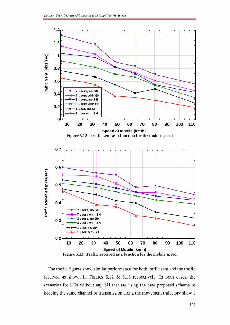
Chapter Five: Mobility Management in Cognitive Networks
151
Figure 5.12: Traffic sent as a function for the mobile speed
Figure 5.13: Traffic received as a function for the mobile speed
The traffic figures show similar performance for both traffic sent and the traffic
received as shown in Figures 5.12 & 5.13 respectively. In both cases, the
scenarios for UEs without any SH that are using the new proposed scheme of
keeping the same channel of transmission along the movement trajectory show a
10 20 30 40 50 60 70 80 90 100 1100
0.2
0.4
0.6
0.8
1
1.2
1.4
Tra
ffic
Sen
t (p
kts
/sec)
Speed of Mobile (km/h)
7 users, no SH7 users, no SH
7 users with SH7 users with SH
3 users, no SH3 users, no SH
3 users with SH3 users with SH
1 user, no SH1 user, no SH
1 user with SH1 user with SH
10 20 30 40 50 60 70 80 90 100 1100.2
0.3
0.4
0.5
0.6
0.7
Tra
ffic
Receiv
ed
(p
kts
/sec)
Speed of Mobile (km/h)
7 users, no SH7 users, no SH
7 users with SH7 users with SH
3 users, no SH3 users, no SH
3 users with SH3 users with SH
1 user, no SH1 user, no SH
1 user with SH1 user with SH
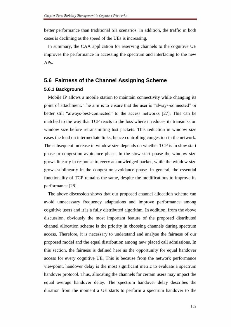
Chapter Five: Mobility Management in Cognitive Networks
152
better performance than traditional SH scenarios. In addition, the traffic in both
cases is declining as the speed of the UEs is increasing.
In summary, the CAA application for reserving channels to the cognitive UE
improves the performance in accessing the spectrum and interfacing to the new
APs.
5.6 Fairness of the Channel Assigning Scheme
5.6.1 Background
Mobile IP allows a mobile station to maintain connectivity while changing its
point of attachment. The aim is to ensure that the user is “always-connected” or
better still “always-best-connected” to the access networks [27]. This can be
matched to the way that TCP reacts to the loss where it reduces its transmission
window size before retransmitting lost packets. This reduction in window size
eases the load on intermediate links, hence controlling congestion in the network.
The subsequent increase in window size depends on whether TCP is in slow start
phase or congestion avoidance phase. In the slow start phase the window size
grows linearly in response to every acknowledged packet, while the window size
grows sublinearly in the congestion avoidance phase. In general, the essential
functionality of TCP remains the same, despite the modifications to improve its
performance [28].
The above discussion shows that our proposed channel allocation scheme can
avoid unnecessary frequency adaptations and improve performance among
cognitive users and it is a fully distributed algorithm. In addition, from the above
discussion, obviously the most important feature of the proposed distributed
channel allocation scheme is the priority in choosing channels during spectrum
access. Therefore, it is necessary to understand and analyse the fairness of our
proposed model and the equal distribution among new placed call admissions. In
this section, the fairness is defined here as the opportunity for equal handover
access for every cognitive UE. This is because from the network performance
viewpoint, handover delay is the most significant metric to evaluate a spectrum
handover protocol. Thus, allocating the channels for certain users may impact the
equal average handover delay. The spectrum handover delay describes the
duration from the moment a UE starts to perform a spectrum handover to the
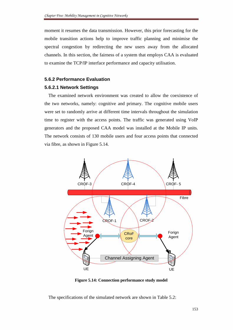
Chapter Five: Mobility Management in Cognitive Networks
153
moment it resumes the data transmission. However, this prior forecasting for the
mobile transition actions help to improve traffic planning and minimise the
spectral congestion by redirecting the new users away from the allocated
channels. In this section, the fairness of a system that employs CAA is evaluated
to examine the TCP/IP interface performance and capacity utilisation.
5.6.2 Performance Evaluation
5.6.2.1 Network Settings
The examined network environment was created to allow the coexistence of
the two networks, namely: cognitive and primary. The cognitive mobile users
were set to randomly arrive at different time intervals throughout the simulation
time to register with the access points. The traffic was generated using VoIP
generators and the proposed CAA model was installed at the Mobile IP units.
The network consists of 130 mobile users and four access points that connected
via fibre, as shown in Figure 5.14.
Forign
AgentCRoF
core
CROF-3 CROF- 5
CROF-1 CROF-2
UE UE
CROF-4
Forign
Agent
Channel Assigning Agent
Fibre
Figure 5.14: Connection performance study model
The specifications of the simulated network are shown in Table 5.2:
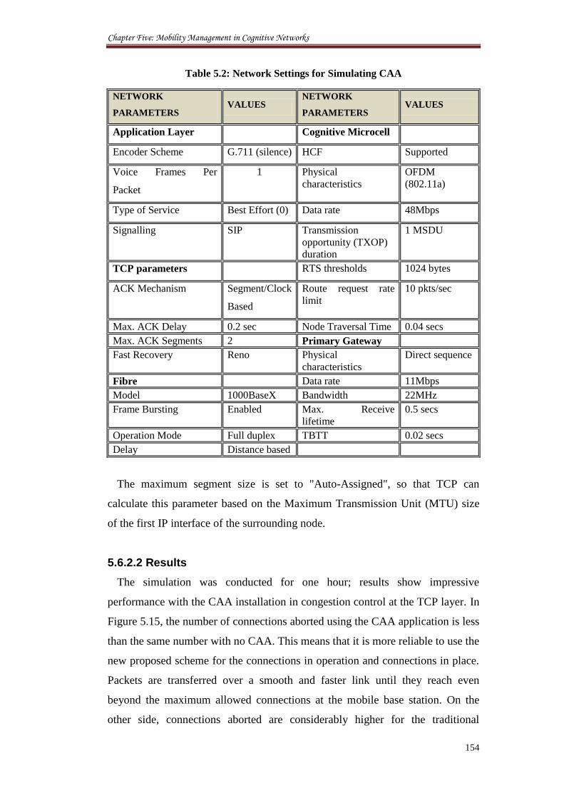
Chapter Five: Mobility Management in Cognitive Networks
154
Table 5.2: Network Settings for Simulating CAA
NETWORK
PARAMETERS VALUES
NETWORK
PARAMETERS VALUES
Application Layer Cognitive Microcell
Encoder Scheme G.711 (silence) HCF Supported
Voice Frames Per
Packet
1 Physical
characteristics
OFDM
(802.11a)
Type of Service Best Effort (0) Data rate 48Mbps
Signalling SIP Transmission
opportunity (TXOP)
duration
1 MSDU
TCP parameters RTS thresholds 1024 bytes
ACK Mechanism Segment/Clock
Based
Route request rate
limit
10 pkts/sec
Max. ACK Delay 0.2 sec Node Traversal Time 0.04 secs
Max. ACK Segments 2 Primary Gateway
Fast Recovery Reno Physical
characteristics
Direct sequence
Fibre Data rate 11Mbps
Model 1000BaseX Bandwidth 22MHz
Frame Bursting Enabled Max. Receive
lifetime
0.5 secs
Operation Mode Full duplex TBTT 0.02 secs
Delay Distance based
The maximum segment size is set to "Auto-Assigned", so that TCP can
calculate this parameter based on the Maximum Transmission Unit (MTU) size
of the first IP interface of the surrounding node.
5.6.2.2 Results
The simulation was conducted for one hour; results show impressive
performance with the CAA installation in congestion control at the TCP layer. In
Figure 5.15, the number of connections aborted using the CAA application is less
than the same number with no CAA. This means that it is more reliable to use the
new proposed scheme for the connections in operation and connections in place.
Packets are transferred over a smooth and faster link until they reach even
beyond the maximum allowed connections at the mobile base station. On the
other side, connections aborted are considerably higher for the traditional
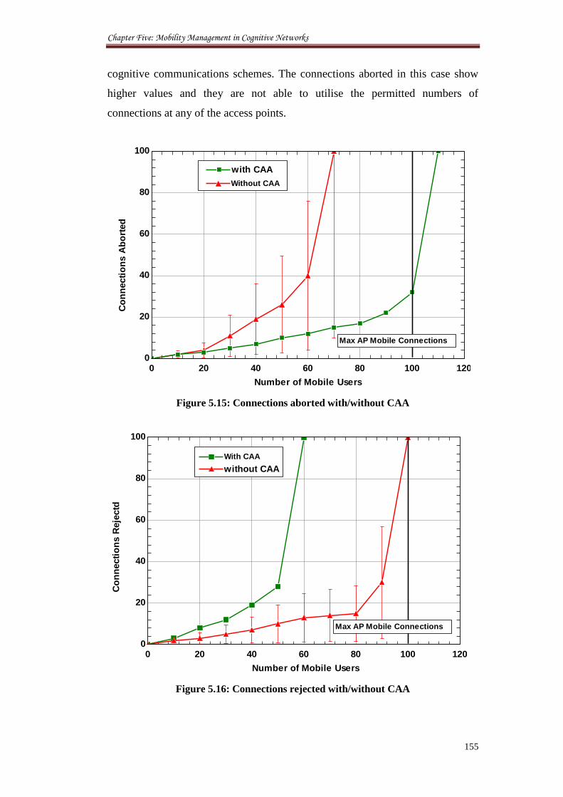
Chapter Five: Mobility Management in Cognitive Networks
155
cognitive communications schemes. The connections aborted in this case show
higher values and they are not able to utilise the permitted numbers of
connections at any of the access points.
Figure 5.15: Connections aborted with/without CAA
Figure 5.16: Connections rejected with/without CAA
0 20 40 60 80 100 1200
20
40
60
80
100
Number of Mobile Users
Co
nn
ecti
on
s A
bo
rted
with CAAwith CAA
Without CAAWithout CAA
Max AP Mobile Connections
0 20 40 60 80 100 1200
20
40
60
80
100
Number of Mobile Users
Co
nn
ecti
on
s R
eje
ctd
Max AP Mobile Connections
without CAAwithout CAA
With CAAWith CAA
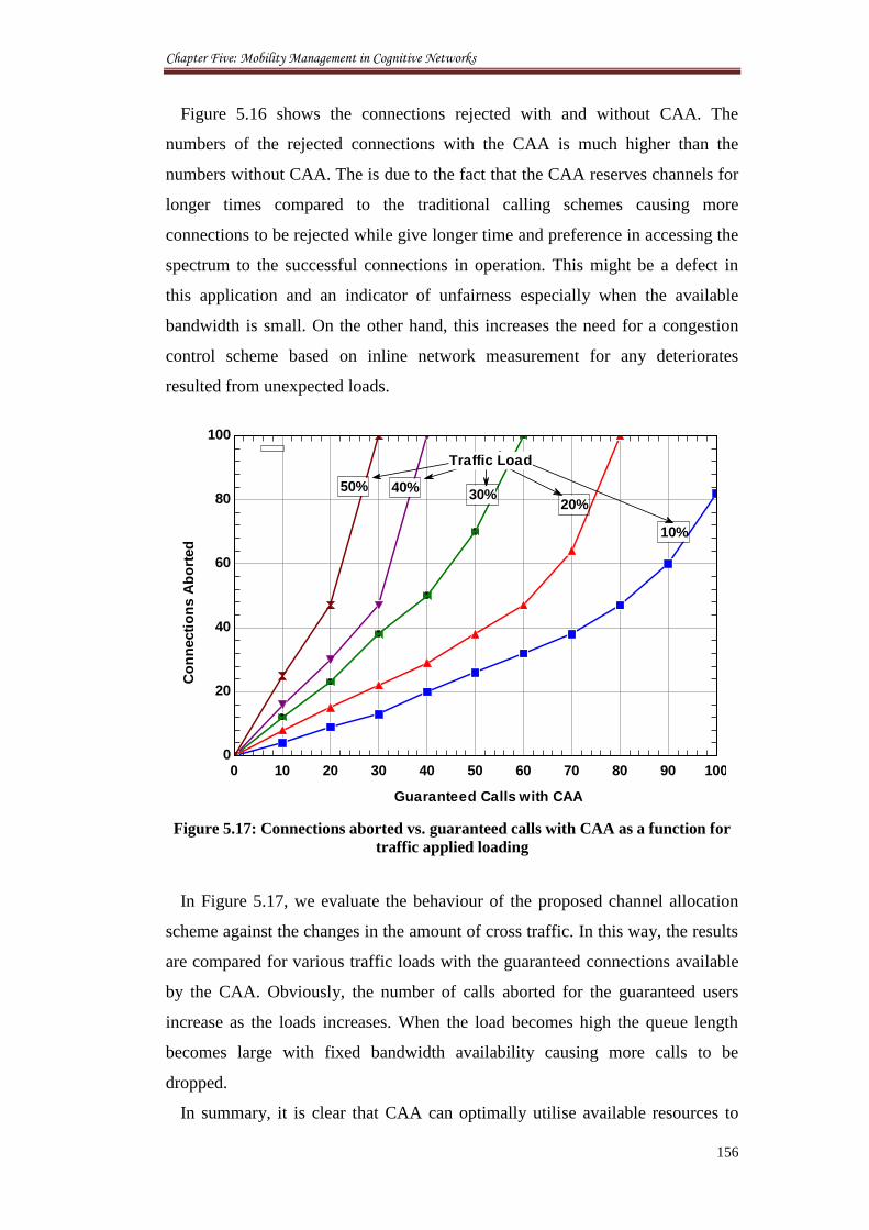
Chapter Five: Mobility Management in Cognitive Networks
156
Figure 5.16 shows the connections rejected with and without CAA. The
numbers of the rejected connections with the CAA is much higher than the
numbers without CAA. The is due to the fact that the CAA reserves channels for
longer times compared to the traditional calling schemes causing more
connections to be rejected while give longer time and preference in accessing the
spectrum to the successful connections in operation. This might be a defect in
this application and an indicator of unfairness especially when the available
bandwidth is small. On the other hand, this increases the need for a congestion
control scheme based on inline network measurement for any deteriorates
resulted from unexpected loads.
Figure 5.17: Connections aborted vs. guaranteed calls with CAA as a function for
traffic applied loading
In Figure 5.17, we evaluate the behaviour of the proposed channel allocation
scheme against the changes in the amount of cross traffic. In this way, the results
are compared for various traffic loads with the guaranteed connections available
by the CAA. Obviously, the number of calls aborted for the guaranteed users
increase as the loads increases. When the load becomes high the queue length
becomes large with fixed bandwidth availability causing more calls to be
dropped.
In summary, it is clear that CAA can optimally utilise available resources to
0 10 20 30 40 50 60 70 80 90 1000
20
40
60
80
100
Guaranteed Calls with CAA
Co
nn
ecti
on
s A
bo
rted
10%
20%30%
40%50%
Traffic Load
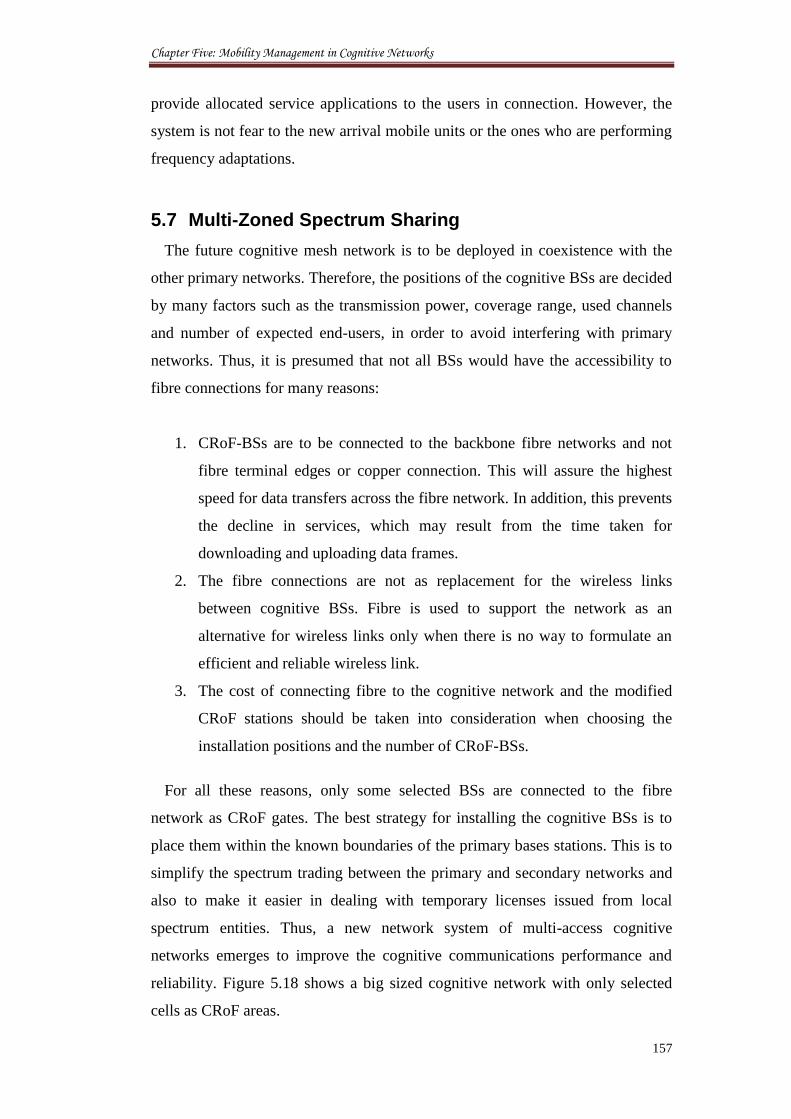
Chapter Five: Mobility Management in Cognitive Networks
157
provide allocated service applications to the users in connection. However, the
system is not fear to the new arrival mobile units or the ones who are performing
frequency adaptations.
5.7 Multi-Zoned Spectrum Sharing
The future cognitive mesh network is to be deployed in coexistence with the
other primary networks. Therefore, the positions of the cognitive BSs are decided
by many factors such as the transmission power, coverage range, used channels
and number of expected end-users, in order to avoid interfering with primary
networks. Thus, it is presumed that not all BSs would have the accessibility to
fibre connections for many reasons:
1. CRoF-BSs are to be connected to the backbone fibre networks and not
fibre terminal edges or copper connection. This will assure the highest
speed for data transfers across the fibre network. In addition, this prevents
the decline in services, which may result from the time taken for
downloading and uploading data frames.
2. The fibre connections are not as replacement for the wireless links
between cognitive BSs. Fibre is used to support the network as an
alternative for wireless links only when there is no way to formulate an
efficient and reliable wireless link.
3. The cost of connecting fibre to the cognitive network and the modified
CRoF stations should be taken into consideration when choosing the
installation positions and the number of CRoF-BSs.
For all these reasons, only some selected BSs are connected to the fibre
network as CRoF gates. The best strategy for installing the cognitive BSs is to
place them within the known boundaries of the primary bases stations. This is to
simplify the spectrum trading between the primary and secondary networks and
also to make it easier in dealing with temporary licenses issued from local
spectrum entities. Thus, a new network system of multi-access cognitive
networks emerges to improve the cognitive communications performance and
reliability. Figure 5.18 shows a big sized cognitive network with only selected
cells as CRoF areas.
Chapter Five: Mobility Management in Cognitive Networks
158
Figure 5.18: Multi-access cellular network of CRoF and CR base stations
The CRoF cells will attract neighbouring cognitive cells to use CRoFs fibre
connections for data exchanges in severe wireless situations. This is likely to
happen whenever a cognitive BS fails to establish a link with remote sites of the
network [29, 30]. These groups of CRoF and cognitive cells that share the same
wireless environment conditions split the network into different zones of
services. In each zone, CRoF acts as the master for all other cognitive cells. This
division makes it easier to achieve local resources sharing between each zone
cells while CRoF cell as a main hub of communications. The spectrum channels
are shared in a distributed way between the zone cells and using the same
proposals in this chapter. In fact, the CRoF acts as a subnet that is quite similar to
what neurons do in the human’s body. The CRoF exchanges data, information,
transmission requests with other zone sites using its landline connection and via
the other sites CRoF cells. The new network architecture can be defined as a new
hybrid system for dynamic spectrum access using local, central-to-local, and
global network resources management. The advantages of multi-zoned
application to future cognitive networks can be summarised as:
1. Novel Base Stations that is integrated to landline access. These are
chosen based to long-term monitoring for the traffic loads and availability
of free spectrum at local areas.
Chapter Five: Mobility Management in Cognitive Networks
159
2. More independent cells that are able to reconfigure and adapt to various
wireless spectral situations and network interfacing managements. This
requires an extended cognition engine designs for the cognitive Base
Stations and new protocols for transferring knowledge between different
network stations as in [31].
3. Establishing temporal, local, flexible zones of neighboured cognitive
cells. These formulations may ease the access procedure and mobility
managements in smaller areas of one pool of spectrum channels.
4. New mobility schemes that can deal with cells rather than individual
mobile stations. The main goal is to create a system that can respond and
act to unpredicted wireless spectral changes and various numbers of
users.
5. Reducing complexity of dealing with main spectrum entities by
establishing local governing units supported by protocols. The
cooperation between various cells is necessary for the success of the
proposed models.
The following sections will investigate the criterion for the formulation of
these zones, changes in the zones’ sizes and boundaries, and the possible
scenarios for cognitive cell migration between these zones. This new paradigm of
local resources sharing through architectural adaptation between the secondary
systems is a subject for evaluation using route optimised cellular MIP protocol
[32].
5.8 Cell Migration between Zones of Service
The zoned cell groups are proposed to be dynamically changeable formulations
to host and release new cognitive cells. In other words, cognitive cells may join
or leave zones at any time as their wireless spectral situation change. These
changes in wireless environment may result from the dynamic activities of the
primary users. Such changes may affect local wireless environment at certain
cells and make them different to the other cells inside a definite zone.
Consequently, a cell may decide to leave a certain zone and join another one or
even stay as an independent cell, according to the negotiations between the cell
BS and other neighboured zones. This section analyses briefly the possible
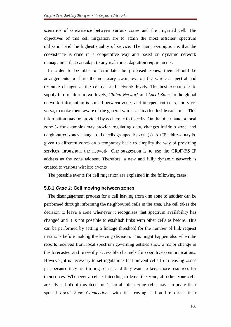
Chapter Five: Mobility Management in Cognitive Networks
160
scenarios of coexistence between various zones and the migrated cell. The
objectives of this cell migration are to attain the most efficient spectrum
utilisation and the highest quality of service. The main assumption is that the
coexistence is done in a cooperative way and based on dynamic network
management that can adapt to any real-time adaptation requirements.
In order to be able to formulate the proposed zones, there should be
arrangements to share the necessary awareness on the wireless spectral and
resource changes at the cellular and network levels. The best scenario is to
supply information in two levels, Global Network and Local Zone. In the global
network, information is spread between zones and independent cells, and vice-
versa, to make them aware of the general wireless situation inside each area. This
information may be provided by each zone to its cells. On the other hand, a local
zone (x for example) may provide regulating data, changes inside a zone, and
neighboured zones change to the cells grouped by zone(x). An IP address may be
given to different zones on a temporary basis to simplify the way of providing
services throughout the network. One suggestion is to use the CRoF-BS IP
address as the zone address. Therefore, a new and fully dynamic network is
created to various wireless events.
The possible events for cell migration are explained in the following cases:
5.8.1 Case 1: Cell moving between zones
The disengagement process for a cell leaving from one zone to another can be
performed through informing the neighboured cells in the area. The cell takes the
decision to leave a zone whenever it recognises that spectrum availability has
changed and it is not possible to establish links with other cells as before. This
can be performed by setting a linkage threshold for the number of link request
iterations before making the leaving decision. This might happen also when the
reports received from local spectrum governing entities show a major change in
the forecasted and presently accessible channels for cognitive communications.
However, it is necessary to set regulations that prevent cells from leaving zones
just because they are turning selfish and they want to keep more resources for
themselves. Whenever a cell is intending to leave the zone, all other zone cells
are advised about this decision. Then all other zone cells may terminate their
special Local Zone Connections with the leaving cell and re-direct their
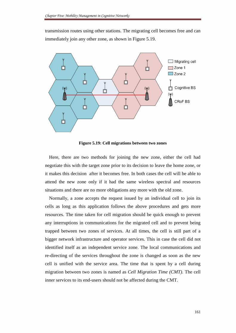
Chapter Five: Mobility Management in Cognitive Networks
161
transmission routes using other stations. The migrating cell becomes free and can
immediately join any other zone, as shown in Figure 5.19.
Figure 5.19: Cell migrations between two zones
Here, there are two methods for joining the new zone, either the cell had
negotiate this with the target zone prior to its decision to leave the home zone, or
it makes this decision after it becomes free. In both cases the cell will be able to
attend the new zone only if it had the same wireless spectral and resources
situations and there are no more obligations any more with the old zone.
Normally, a zone accepts the request issued by an individual cell to join its
cells as long as this application follows the above procedures and gets more
resources. The time taken for cell migration should be quick enough to prevent
any interruptions in communications for the migrated cell and to prevent being
trapped between two zones of services. At all times, the cell is still part of a
bigger network infrastructure and operator services. This in case the cell did not
identified itself as an independent service zone. The local communications and
re-directing of the services throughout the zone is changed as soon as the new
cell is unified with the service area. The time that is spent by a cell during
migration between two zones is named as Cell Migration Time (CMT). The cell
inner services to its end-users should not be affected during the CMT.
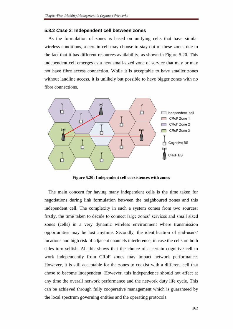
Chapter Five: Mobility Management in Cognitive Networks
162
5.8.2 Case 2: Independent cell between zones
As the formulation of zones is based on unifying cells that have similar
wireless conditions, a certain cell may choose to stay out of these zones due to
the fact that it has different resources availability, as shown in Figure 5.20. This
independent cell emerges as a new small-sized zone of service that may or may
not have fibre access connection. While it is acceptable to have smaller zones
without landline access, it is unlikely but possible to have bigger zones with no
fibre connections.
Figure 5.20: Independent cell coexistences with zones
The main concern for having many independent cells is the time taken for
negotiations during link formulation between the neighboured zones and this
independent cell. The complexity in such a system comes from two sources:
firstly, the time taken to decide to connect large zones’ services and small sized
zones (cells) in a very dynamic wireless environment where transmission
opportunities may be lost anytime. Secondly, the identification of end-users’
locations and high risk of adjacent channels interference, in case the cells on both
sides turn selfish. All this shows that the choice of a certain cognitive cell to
work independently from CRoF zones may impact network performance.
However, it is still acceptable for the zones to coexist with a different cell that
chose to become independent. However, this independence should not affect at
any time the overall network performance and the network duty life cycle. This
can be achieved through fully cooperative management which is guaranteed by
the local spectrum governing entities and the operating protocols.

Chapter Five: Mobility Management in Cognitive Networks
163
5.8.3 Case 3: Cell trapped by one zone
The unification of different cognitive cells having the same resources may lead
to the isolation of a certain cell with different wireless situations, as shown in
Figure 5.21. This cell is actually trapped by the same zone cells from all sides.
This may happen if the cell leaves the zone after being part of it. In fact, this
situation can happen when two neighboured zones choose to bond together as
one zone leaving one cell in the middle. Suddenly, this cell finds itself trapped
between the boundaries of this new establishment with no other choices to take.
Figure 5.21: Independent cell trapped by one zone
Practically, this is a critical situation for the trapped cell in achieving high
levels of cooperation with other zone stations. To maintain seamless
communications in this specific scenario, the zone has to give its cells that
surround the trapped cell the authority to communicate directly with this free cell
without central approval. In this way, a distributed access is approved to
overcome the delay resulted from requests to communicate with a small coverage
area as this. There is an expected increase in the complexity of running such a
network because of the long procedures of having one cell standalone between
zone boundaries. However, the complexity may increase further in case the cell
is forced to join a zone of unmatched wireless situations. Therefore, it is
preferable to oblige with the general rules of balancing services by reunifying
only similar cells rather than adding one more different cell.
As for being dynamic sets, the zone sizes, places, cell members, and shared
Chapter Five: Mobility Management in Cognitive Networks
164
resources may change at any time due to the activities of the primary users and
the technical difficulties/differences in adjusting transmission functions.
Therefore, negotiations are undergoing between all cells at all times to achieve
the highest QoS in responding to clients’ requests and spectrum developments.
5.9 Conclusion
A novel scheme is proposed to reduce the spectrum handover in the future
cognitive networks that employ sectored macrocells. A new entity named as
Channel Assigning Agent is introduced at the mobile IP to allocate the same
channel used by the cognitive mobile station to it whenever it moves inside the
macrocellular sub-areas. The main goal of this design is to reduce the
interruption time during frequency adaptation and the redundant unnecessary
spectrum handovers for a UE travelling at various speeds. The solution involved
the design of algorithms that scans the available band for the channel in
operation before any decision of shifting to other frequencies. Results show
considerable improvement in throughput, AP connectivity and major savings in
time delay. The fairness of the proposed scheme was evaluated to show the
connections aborted and rejected as a function for allocating certain channels to
certain users. The work has been developed further by partitioning the cognitive
networks into different zones to ease the management and access of resources,
using both wireless and fibre connections. These zones are composed of a group
of cognitive cells mastered by the CRoF cell, with optional attendance. The
boundaries and size of any of these zones can change at any time due to the
dynamical wireless changes. Various scenarios for cells leaving and joining
zones are surveyed and discussed. The aim of this proposal is to identify a new
local resources sharing scheme through topology adjustments. New topics are
raised to the research community by analysing new IPv6 models for the cognitive
networks.
5.10 References
[1] I. F. Akyildiz, W. Y. Lee, M. C. Vuran, and S. Mohanty, “A Survey on
Spectrum Management in Cognitive Radio Networks,” IEEE
Communication Magazine, vol. 46, no. 4, 2008, pp. 40 - 48.
Chapter Five: Mobility Management in Cognitive Networks
165
[2] A. MacKenzie, J. Reed, P. Athanas, C. Bostian, R. Buehrer, L. DaSilva, S.
Ellingson, Y. Hou, M. Hsiao, J. Park, C. Patterson, S. Raman, and C. da
Silva, “Cognitive Radio and Networking Research at Virginia Tech,”
Proceedings of the IEEE , vol. 97, no. 4, 2009, pp. 660 - 688.
[3] D. Niyato and E. Hossain, “Cognitive Radio for Next-Generation Wireless
Networks: An Approach to Opportunistic Channel Selection in IEEE
802.11–Based Wireless Mesh,” IEEE Wireless Communications, vol. 16,
no. 1, 2009, pp. 46 - 54.
[4] S. Mangold, J. Habetha, S. Choi, and C. Ngo, “Coexistence and
Interworking of IEEE 802.11a and ETSI BRAN HiperLAN/2 in MultiHop
Scenarios,” In proceedings of the 3rd
IEEE Workshop in Wireless Local
Area Networks, Boston, USA, 2001, pp. 27 - 28.
[5] K. Watanabe and K. Ishibashi, “Performance of Cognitive Radio
Technologies in the Presence of Primary Radio Systems,” In proceedings
of the 18th
Annual IEEE International Symposium on Personal, Indoor and
Mobile Radio Communications (PIMRC’07), Toronto, Canada, 2007, pp. 1
- 5.
[6] V. Rohokale, N. Kulkarni, N. Prasad, and H. Cornean, “Cooperative
Opportunistic Large Array Approach for Cognitive Radio Networks,” In
proceedings of the 8th
International Conference on Communications
(COMM), Bucharest, Romania, 2010, pp. 513 - 516.
[7] H. Arslan (Ed.), Cognitive Radio, Software Defined Radio, and Adaptive
Wireless Systems. Dordrecht, The Netherlands: Springer, 2007.
[8] R. S. Komali, R. W. Thomas, L. A. DaSilva, and A. B. MacKenzie, “The
Price of Ignorance: Distributed Topology Control in Cognitive Networks,”
IEEE Transactions on Wireless Communications, vol. 9, no. 4, 2010, pp.
1434 - 1445.
[9] Y. Chung and Z. Tsai, “Performance evaluation of dynamic spectrum
sharing for two wireless communication Networks,” IET Communications,
vol. 4, no. 4, 2010, pp. 452 - 462.
[10] J. Huschke and P. Leaves, “Dynamic Spectrum Allocation Algorithm
Including Results of DSA Performance Simulations,” DRiVE Deliverable
D09, Information Society Technologies, 2003.
Chapter Five: Mobility Management in Cognitive Networks
166
[11] Y. Yuan, P. Bahl, R. Chandra, P. Chou, J. Ferrell, T. Moscibroda, S.
Narlanka, and Y. Wu, “KNOWS: Kognitiv Networking over White
Spaces,” In proceedings of the IEEE DySPAN, Dublin, Ireland, 2007, pp.
416 - 427.
[12] D. Chen, Q. Zhang, and W. Jia, “Aggregation Aware Spectrum
Assignment in Cognitive Ad-hoc Networks,” In proceedings of the 3rd
International ICST Conference on Cognitive Radio Oriented Wireless
Networks (CrownCom), Singapore, 2008, pp. 1 - 6.
[13] J. Jia, Q. Zhang, and X. Shen, “HC-MAC: A Hardware-Constrained
Cognitive MAC for Efficient Spectrum Management,” IEEE Journal on
Selected Areas in Communications, vol. 26, no. 1, 2008, pp. 106 - 117.
[14] E. Re, R. Fantacci, and G. Giambene, “Handover and dynamic channel
allocation techniques in mobile cellular networks,” IEEE Transactions on
Vehicular Technology, vol. 44, no. 2, 1995, pp. 229 - 237.
[15] J. M. Chung, C.H. Kim, J. H. Park, J. Shin and D. Kim, “Optimal channel
allocation for cognitive Radios,” IET Electronics Letters, vol. 46, no. 11,
2010, pp. 802 - 803.
[16] Z. Damljanovic, “Mobility Management Strategies in Heterogeneous
Cognitive Radio Networks,” Journal of Network and Systems
Management, vol. 18, no. 1, 2010, pp. 4 - 22.
[17] I. F. Akyildiz, W. Y. Lee, and K. R. Chowdhury, “CRAHNs: Cognitive
Radio Ad Hoc Networks,” Journal of Ad Hoc Networks, vol. 7, no. 5,
2009, pp. 810 - 836.
[18] J. Sun and J. Sauvola “Mobility and Mobility Management: A Conceptual
Framework,” In proceedings of the 10th IEEE International Conference on
Networks (ICON2002), Singapore, pp. 205 - 210.
[19] OPNET help, www.opnet.com. Accessed: July, 10, 2012.
[20] G. Lampropoulos, N. Passas, L. Merakos, and A. Kaloxylos, “Handover
Management Architectures in Integrated WLAN/Cellular Networks,” IEEE
Communications Surveys & Tutorials, vol. 7, no. 4, 2005, pp. 30 - 44.
[21] M. Stemm and R. H. Katz, “Vertical handoffs in wireless overlay
networks,” Mobile Networks and Applications, no. 3, 1998, pp. 335 - 350.
Chapter Five: Mobility Management in Cognitive Networks
167
[22] J. Sen, “Mobility and Handoff Management in Wireless Networks,” in
Trends in Telecommunications Technologies, C. J. Bouras (Ed.), New
York: InTech, 2010, pp. 457 - 484.
[23] J. Mitola, Cognitive Radio Architecture: The Engineering Foundations of
Radio XML, Hoboken/New Jersey, John Wiley and Sons Inc, 2006.
[24] Ulvan, R. Bestak, and M. Ulvan, “Handover Scenario and Procedure in
LTE-based Femtocell Networks,” In proceedings of the 4th International
Conference on Mobile Ubiquitous Computing, Systems, Services and
Technologies (UBICOMM 2010), Florence, Italy, 2010, pp. 213 - 218.
[25] K. C. Chen and R. Prasad, Cognitive Radio Networks, Chichester, West
Sussex, John Wiley & Sons Ltd, 2009.
[26] IEEE 802.22 WRAN, “A PHY/MAC Proposal for IEEE 802.22 WRAN
System Part 2: The Cognitive MAC,” March 2006. Online:
http://www.ieee802.org/22, Accessed: July 20, 2012.
[27] R. C. Dorf, Broadcasting and Optical Communication Technology, Boca
Raton, FL, Taylor & Francis Group, 2006.
[28] T. Issariyakul, L. S. Pillutla, and V. Krishnamurthy, “Tuning Radio
Resource in an Overlay Cognitive Radio Network for TCP: Greed Isn’t
Good,” IEEE Communications Magazine, vol. 47, no. 7, 2009, pp. 57 - 63.
[29] A. Al-Dulaimi, H. S. Al-Raweshidy, J. Cosmas, and J. Loo, “Cognitive
Mesh Networks, Cognitive Radio over Fibre for Microcells Application”,
IEEE Vehicular Technology Magazine, vol. 5, no. 3, 2010, pp. 54 - 60.
[30] A. Al-Dulaimi, S. Al-Rubaye, H. S. Al-Raweshidy, J. Cosmas, and K. K.
Loo, “Multi-Zones of Cognitive to Fibre Networks,” In proceedings of the
7th
International Symposium on Communication Systems, Networks and
Digital Signal Processing (CSNDSP), Newcastle upon Tyne, UK, 2010,
pp. 697 - 700.
[31] A. Al-Dulaimi and L. AL-Saeed, “An Intelligent Scheme for First Run
Cognitive Radios,” In proceedings of the 4th
IEEE International
Conference and Exhibition on Next Generation Mobile Applications,
Services, and Technologies (NGMAST'10), Amman, 2010, pp. 158 - 161.
[32] J. Postel. RFC 792: Internet Control Message Protocol. September 1981.
Chapter Six: Conclusions and Future Work
168
Chapter 6
Conclusions and Future Work
6.1 Conclusions
There is no predictable paradigm for expanding the cognitive network capacity
or dealing with the dynamic spectrum access challenges through architectural
solutions. However, it is acceptable that installing ever increasing numbers of
macrocell BS towers with improved techniques can increase the network
competence. The key problem with adding more macrocell (or microcell) BSs is
a) they may not be able to communicate between each other or even formulate a
wireless link due to the spectrum availability, and b) these deployments do not
scale well with the ever increasing demand for data rates for reasons of mobility
and scarce availability of spectrum.
In contrast, supplementary landline infrastructure in the form of fibre
connected to distributed microcells restructure wireless capacity by exploiting
the relative proximity of users to their AP (thereby reducing the average
transmit–receive communication distance). This results in a greater number of
local transmission opportunities and power consumption models. Because these
technologies potentially require integration between many networks, cellular and
fibre operators can recoup their initial investments into one powerful wireless–to–
fibre access network and offer better service, while consuming less spectrum.
This thesis has addressed the key technical challenges confronting tiered
cellular wireless systems when macro and micro users either share radio
spectrum or operate over orthogonal spectrum. Our main goals are that tiered
Chapter Six: Conclusions and Future Work
169
networks with one spectrum pool will be significantly encumbered by the
terminal radio technologies and the distribution of microcells over the cellular
networks. Specifically, there is a fundamental tradeoff between providing finding
the mobile user location and providing reliable diverted call. This is performed
with high level of coordination between the macrocell and microcells BSs
transmissions using the fibre as part of the backbone network. The net
consequence is that accommodating greater numbers of microcells (or providing
higher microcell data rates) reduces the number of cellular users that can reliably
operate in the same spectrum beyond certain levels. Without resources
management, adding microcells will likely be self-defeating, because of the
potentially likely disruption in reliable coverage of the cognitive cellular
infrastructure under the assumption of no impacts on the primary network.
The focus of this work has been to address decentralised radio management in
microcell-aided cellular architectures, encompassing a variety of physical layer
technologies, through a combination of resources filling and sharing, power
control and mobility management for alleviating spectrum scarcity and
improving system capacity. With interference avoidance, the new heterogeneous
network users attempt to avoid causing mutual collisions (through landline
connections and dividing the coverage zones).
Improving capacity is achieved by forcing microcells to choose their end–users
(and hence their transmit powers) for minimising the unnecessary spectrum
usage. This thesis has developed an algorithm to divert calls between the new
combined cognitive BS through fibre network rather than establishing wireless
connections, a road map for the deployment capacities of cognitive users and
power control analysation for the power gained from diverting calls across the
microcellular system. The efficacy of these resources filling and power control
schemes has been evaluated in typical coexistence scenarios with large number
of microcells deployed. Finally, novel mobility schemes are suggested in this
thesis to reduce the unnecessary spectrum handovers in two-tier networks using
developed IP algorithms, this is done by allocating the same channel in operation
for a mobile user that travels between different domains while guaranteeing a
minimum desirable service to new users in either tier.
Chapter Six: Conclusions and Future Work
170
6.2 Future Work
Adaptive and open–access microcell operation will cause the cellular users
experiencing radio interference at both the macrocell and microcell BSs. It is
reasonable to assume that a practical system would assign weighted priorities to
serviced users with high competition on valuable resources and consumers
receiving higher priority of higher biddings. Because the microcells transport
their traffic over the fibre network, it is important to understand the impacts of
diverting calls over the landline on the fibre capacity, power consumption, time
delays of signals conversion, and the Quality-of-Service for the whole system
technical design.
An open research problem is to analyse which mode of operation (one pool or
frequency re-use) is preferable either from the perspective of avoiding inference
and efficient sharing of resources (as an instance, which operation yields a higher
average throughput), or from the perspective of the entire network (a centralised
entity could maximise the network-wide spatial reuse by determining two classes
of wireless domains: one would provide one core for each macrocell domain, and
the other set would operate cross connections between microcells). The
implication is that microcells would adaptively configure their access mode
depending on their location, the prevailing levels of co-channel interference, the
channel conditions between users to their BSs, the number of already serviced
users in each microcell and their prevailing target data rates.
In multi–zoned network operation, the dynamic changes of the network
combinations overhead arising the need to dynamically update the routing tables
of the available links and stations locations. These dynamically updated routing
tables contain information about the topology of the network immediately around
it. These routes should be an entries made in a routing table by automatic means
and as a result of instant network topology “discovery” procedure. This
information is delivered latter to the macrocells nodes to enable them to adjust
their position within and between zones. This is a serious challenge for the
practical deployments of large numbers of microcells in such divided networks.
One method of minimising frequent handover events is that microcells
dynamically adapt their coverage radius depending on the changes in the
backbone network zone connections, channel conditions, number of users served
Chapter Six: Conclusions and Future Work
171
by each microcell, and the numbers of newly installed microcells. This will
generate new unidirectional shared trees of routes per group, and optionally
creates shortest-path trees per source. The problem of determining the “optimal"
network coverage, as a function of the available bandwidth and user mobility, is
an open avenue for further research.