cof seal oil 1-5
DESCRIPTION
ÂTRANSCRIPT

TVA
Operations Continuing Training
Tennessee Valley Authority
TVA
Colbert Units’ 1-5 Hydrogen Seal Oil System

2 Colbert Units’ 1-5 Hydrogen Seal Oil System
Table of Contents Units’ 1-4
TABLE OF CONTENTS ......................................................................................................................................................................................
LIST OF FIGURES ..............................................................................................................................................................................................3
STUDENT OBJECTIVES ..................................................................................................................................................................................4
SYSTEM OVERVIEW ........................................................................................................................................................................................5
MAJOR COMPONENTS ..................................................................................................................................................................................9 Air Detraining Section ..................................................................................................................................................................9 Hydrogen Detraining Section ................................................................................................................................................. 10 Seal Drain Float Valve ................................................................................................................................................................ 11 Seal Oil Supply Unit ..................................................................................................................................................................... 12 Oil Storage Tank ......................................................................................................................................................... 12 Vacuum Tank ....................................................................................................................................................... 12-13 Main Seal Oil Pump (MSOP) .............................................................................................. ....................................13 Vacuum Pump.............................................................................................................................................................. 13 Seal Oil Cooler .............................................................................................................................................................. 14 Seal Oil Filter ................................................................................................................................................................ 14 Seal Oil Filter ................................................................................................................................................................ 14 Differential Pressure Regulating Valve ............................................................................................................ 15 Emergency Seal Oil Pump (ESOP) ...................................................................................................................... 15 Emergency Seal Oil Regulator .............................................................................................................................. 16 CONTROL CIRCUITS ................................................................................................................................................................................... 19 Electrical Distributions ...................................................................................................................................................... 19-20 SYSTEM OPERATION ................................................................................................................................................................................. 21 Normal Operation ........................................................................................................................................................................ 21 Degraded Operation ................................................................................................................................................................... 21
ISOLATION POINTS & AUTOMATIC FUNCTIONS ....................................................................................................................... 22
INSTRUMENTATION .................................................................................................................................................................................. 23 Pressure Gauges ........................................................................................................................................................................... 23 Temperature Gauges .................................................................................................................................................................. 23 INDUSTRY REALTED EVENTS .............................................................................................................................................................. 25 References ........................................................................................................................................................................................................... GE Drawing 149D212 ..................................................................................................................................................................... 45W679 H2 Control Cabinet Ann ............................................................................................................................................. 47W842 ................................................................................................................................................................................................ Procedures .......................................................................................................................................................................................................... COF.AOI.10.059.001.U1-U4 Loss of Generator Seals ........................................................................................................ COF.NPD.10.000.009.U1-U4 Seal Oil Vacuum Pump Memo .......................................................................................... COF. SOI. 10. 059. 001. U1-U4 AUO Placing Generator Seal Oil System in Service .............................................. COF. SOI. 10. 059. 002. U1-U4 AUO Placing DC Seal Oil Pump In Service (on-line) ............................................ COF. SOI. 10. 059. 003. U1-U4 AUO Removing Generator Seal Oil from Service .................................................. COF. SOI. 10. 059. 010. U1-U4 Adding Oil to Seal Oil Vacuum Pumps ....................................................................... COF. SOI. 10. 059. 010. U1-U4 Draining the Generator Liquid Detectors ................................................................ COF-SOI- 10. 059. 011. U1-U4 Hydrogen Seal Oil Operational Inspection.............................................................. COF-TI.10.0.0001.U1-4 ................................................................................................................................................................... TASK LIST ........................................................................................................................................................................................................ 26 Unit Operator Tasks ................................................................................................................................................................... 26 Assistant Unit Operator Tasks ............................................................................................................................................... 26

3 Colbert Units’ 1-5 Hydrogen Seal Oil System
List of Figures
Figure 1 Seal Oil Supply to Sealing Rings ............................................................................................................5
Figure 2 Sealing Rings .................................................................................................................................................6
Figure 3 Portion of Seal Oil Diagram (seals and drains) ..............................................................................7
Figure 4 Air Detraining Section ...............................................................................................................................9
Figure 5 Hydrogen Detraining Section .............................................................................................................. 10
Figure 6 Seal Drain Float Valve ............................................................................................................................. 11
Figure 7 Seal Oil Supply Unit ................................................................................................................................. 12
Figure 8 Vacuum Pump ............................................................................................................................................ 13
Figure 9 Seal Oil Cooler ............................................................................................................................................ 14
Figure 10 Seal Oil Filters ............................................................................................................................................ 14
Figure 11 Differential Seal Oil Regulator ............................................................................................................ 15
Figure 12 Emergency Seal Oil Regulator ............................................................................................................. 16
Figure 13 MSOP Electrical Supply .......................................................................................................................... 19
Figure 14 Seal Oil Vacuum Pump Electrical Supply ....................................................................................... 19
Figure 15 ESOP Electrical Supply Rings .............................................................................................................. 20
Figure 16 Hydrogen Seal Oil Unit Annunciation Panel ................................................................................ 24

4 Colbert Units’ 1-5 Hydrogen Seal Oil System
Student Objectives
Define the purpose of the generator seal oil system....................................................................................................
Explain the purpose and function of each component in the generator seal oil system ..............................
Explain the 480v control circuits for the seal oil pumps and the automatic functions associated with
the pumps ......................................................................................................................................................................................
Describe the flow path and normal operating guidelines of the generator seal oil system to include
temperatures, pressures, and levels ...................................................................................................................................
Identify and locate the electrical isolation points for the generator seal oil system ......................................
Identify and locate the mechanical isolation points for the generator seal oil system .................................
Identify local and remote instrumentation, indications, and alarms associated with the generator seal oil system ..............................................................................................................................................................................
5 Colbert Units’ 1-5 Hydrogen Seal Oil System
System Overview
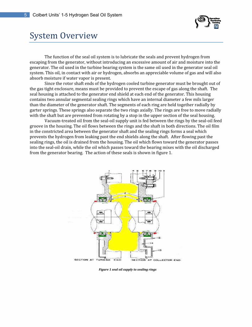
The function of the seal oil system is to lubricate the seals and prevent hydrogen from escaping from the generator, without introducing an excessive amount of air and moisture into the generator. The oil used in the turbine bearing system is the same oil used in the generator seal oil system. This oil, in contact with air or hydrogen, absorbs an appreciable volume of gas and will also absorb moisture if water vapor is present. Since the rotor shaft ends of the hydrogen cooled turbine generator must be brought out of the gas tight enclosure, means must be provided to prevent the escape of gas along the shaft. The seal housing is attached to the generator end shield at each end of the generator. This housing contains two annular segmental sealing rings which have an internal diameter a few mils larger than the diameter of the generator shaft. The segments of each ring are held together radially by garter springs. These springs also separate the two rings axially. The rings are free to move radially with the shaft but are prevented from rotating by a stop in the upper section of the seal housing. Vacuum-treated oil from the seal-oil supply unit is fed between the rings by the seal-oil feed groove in the housing. The oil flows between the rings and the shaft in both directions. The oil film in the constricted area between the generator shaft and the sealing rings forms a seal which prevents the hydrogen from leaking past the end shields along the shaft. After flowing past the sealing rings, the oil is drained from the housing. The oil which flows toward the generator passes into the seal-oil drain, while the oil which passes toward the bearing mixes with the oil discharged from the generator bearing. The action of these seals is shown in figure 1.
Figure 1 seal oil supply to sealing rings

6 Colbert Units’ 1-5 Hydrogen Seal Oil System
The assembly of the seal ring and associated apparatus is shown in figure 2. The seal oil is fed to the feed grooves through passages in the supporting brackets. The seal ring is provided to restrict the flow of oil through the seal. Oil leaving the seal ring is caught in chambers on each side of the seal, from which it is drained back to the seal oil system.
Figure 2 Sealing ring
top of ring
bottom of ring

7 Colbert Units’ 1-5 Hydrogen Seal Oil System
The Seal Oil Diagram in figure 3, shows the complete seal oil system, and illustrates how contaminating air and moisture are kept out of the generator. As the hydrogen side seal oil comes in contact with the bearing oil (air side), it enters a common drain to the air detraining section. The seal oil that comes in contact with the generator hydrogen (hydrogen side) enters the drain piping leading to the hydrogen detraining section. Both sections are designed to de-train (remove) the captured moisture and/or gas entrained in the oil.
Figure 3 portion of seal oil diagram

8 Colbert Units’ 1-5 Hydrogen Seal Oil System
Review Questions
1) Describe, in your own words the purpose of the seal oil system.
____________________________________________________________________________________________________________________________________________________________________________________________________________________________________
2) What does the oil film create to keep the hydrogen in the generator casing?
_______________________________________________
3) The seal ring is provided to _______________ the flow of oil through the seal.
4) The hydrogen seal oil and bearing oil that come in contact with one another drain to what area?
a) The turbine room roof
b) Hydrogen Detraining section
c) Station Sump
d) Air Detraining section
5) The oil that is supplied to the shaft seals is ____________ treated to remove air and moisture, so that air from the oil will not be given up to the hydrogen in the generator, reducing its purity level.
a) barely
b) scavenge
c) vacuum
d) water

9 Colbert Units’ 1-5 Hydrogen Seal Oil System
Major Components
I. Air Detraining Section
The oil from the air side of the seals, and from the ends of the generator bearings adjacent to the seals, flow through a common drain to an enlarged section of pipe designated as the air detraining section. This section serves to de-train air from the oil before it enters the bearing oil drain. This section also serves to remove any hydrogen that may be present due to low seal oil pressure or failure of the sealing rings. In the event of low seal oil pressure, hydrogen is prevented from entering the main turbine oil tank by a loop seal which connects the air detraining section to the bearing drain. The escaping hydrogen is venting to atmosphere through piping that leads to the turbine room roof. The oil level in the seal oil tank is maintained by the connecting drain line from the air-detraining section.
Figure 4 Air Detraining Section

10 Colbert Units’ 1-5 Hydrogen Seal Oil System
II. Hydrogen Detraining Section Two drain pipes, one at each end of the generator, receive the oil discharged from the hydrogen sides of the shaft seals. These pipes connect below the generator into an enlarged horizontal length of pipe, designated as the seal drain enlargement. The drain enlargement provides a large surface area which serves to remove the larger hydrogen bubbles from the oil. A transverse partition divides the enlargement into two compartments, which are connected at the bottom through a loop seal. This arrangement is required to prevent circulation of oil vapor through the seal drain piping resulting from any difference in fan pressures at the two ends of the generator. A liquid detecting device, located at the seal-oil unit, is connected with the drain enlargement through line HSA. This device gives a visual indication of liquid and operates the alarm system if the oil level in the enlargement should rise to the center line. Valves (59-3) and (59-4), connecting with pipes terminating above the oil level at each end of the enlargement, permit gas to be scavenged from the enlargement.
HHD piping to Seal Oil Drain Float Valve HSA piping to Seal Drain High Level Alarm
Figure 5 Hydrogen Detraining Section

11 Colbert Units’ 1-5 Hydrogen Seal Oil System
III. Seal Drain Float Valve Oil from the seal drain enlargement, passes into the seal drain float valve (59-9), via through line HHD. Oil leaves the float valve, which opens with the rise of the float, and passes into the storage tank. The float valve is provided with an oil level gauge. The oil level in the float valve must be maintained above the center line of the float chamber for any operating condition.
Figure 6 Seal Drain Float Valve
59-8
59-9
59-8
59-9 Seal Drain Float Valve

12 Colbert Units’ 1-5 Hydrogen Seal Oil System
IV. Seal Oil Supply Unit The oil supplied to the shaft seals is vacuum treated to remove both air and moisture. Therefore, air from the oil cannot be given up to the hydrogen in the casing and so reduce its purity; and moisture in the generator will be avoided. The treatment and control of the seal oil is accomplished with the following: oil storage tank, vacuum tank, main seal oil and vacuum pump, oil cooler, strainers and regulating valves. The two tanks of the system are built as separate compartments. Figure 7 identifies most of the seal oil supply unit.
Figure 7 Seal Oil Supply Unit
a. Oil Storage Tank The air side seal-oil drains into a vented enlargement (air detraining section) which connects to the main bearing oil drain through a loop seal. The loop seal prevents air or hydrogen from entering the bearing oil drain. The enlargement also connects to the seal oil storage tank and maintains the normal level in the tank by gravity flow through line HAD and valve (59-12). An oil level gauge is provided on the tank. In the hydrogen detraining section, the oil from the hydrogen side of the seals gives up some of the larger bubbles of hydrogen entrained in it. The hydrogen that is detrained passes back to the generator. The seal drain float valve, controlling the outflow from the hydrogen detraining section, opens with a rising float and permits oil admitted to pass to the storage tank.
b. Vacuum Tank Oil from the seal-oil storage tank enters the vacuum tank through float valve (59-14) and through spray nozzles directed upward. Float valve (59-14) closes with rising float to maintain a constant oil level. Some of the gases in the oil entering the vacuum tank are removed as the oil passes through the inlet nozzles. Most of the gas remaining in the oil is removed by recirculation of the oil in the tank through a second set of spray nozzles directed downward. Also through this recirculation of the oil, which is effected by operation of the main seal-oil pump, the oil foam created by the vacuum at the oil surface is broken up so that it does not rise and fill the tank.
Vacuum Tank Seal Drain Float Valve Vacuum Pump Main Seal Oil Pump Emergency Seal Oil Pump
Oil Storage Tank Oil Level Sight Gauge Emergency Differential Regulating Valve Seal Oil Cooler

13 Colbert Units’ 1-5 Hydrogen Seal Oil System
A float-operated switch (63–10) operates on high oil level to close the solenoid-operated valve (20–1) in the vacuum pump suction line to prevent oil or oil foam from being drawn out of the vacuum tank by the vacuum pump. Solenoid valve (20–1) in the vacuum pump suction line is connected electrically with the level alarm switch (63–10) on the vacuum tank and with pressure switch (63–6) on the discharge side of the main seal-oil pump. This connection permits either the occurrence of high oil level in the vacuum tank or failure of the seal-oil pump to close valve (20–1), in order to prevent loss of oil from the vacuum tank through the suction line of the vacuum pump. Failure of the seal-oil pump interrupts the oil flow through the recirculation spray nozzles, which, with vacuum applied, causes foam to build up in the vacuum tank; hence, means for interrupting the vacuum under this condition must be supplied. A holding switch (PB–2) for valve (20–1) is provided which permits manual operation of the valve for test purposes. (refer to print on page 20) Two observation windows on the cover at the end of the tank permit observation of the spray from the nozzles and of the condition of the oil at the oil surface. The pipe at the top of the vacuum tank connects with a low-vacuum alarm switch and a vacuum gauge (G2) at the seal-oil unit control panel. Valve (59-32) connects with line GDR from the gas dryer. Valve (59-28) permits breaking the vacuum in the tank, when this is required.
c. Main Seal Oil Pump (MSOP)
The MSOP is a rotary pump with a capacity several times the requirements of the seals; it takes suction from the vacuum tank and supplies vacuum treated oil to the shaft seals. The excess oil over the seal requirements is returned to the vacuum tank through regulating valve (59-19) and the re-circulating spray nozzles. A strainer at the entrance to the suction line of the pump, located within the vacuum tank, prevents entrance of solid matter into the pump. The pump shaft is provided with a mechanical seal to prevent loss of oil from the pump along the shaft.
d. Vacuum Pump An absolute pressure of approximately 0.5 inch mercury is maintained in the vacuum tank by the operation of a rotary vacuum pump. Oil for sealing and lubricating the vacuum pump is obtained from a separator tank mounted above the pump. The interior of this tank is baffled to aid in the separation of moisture and oil from the gases discharged from the pump. A gravity drain arrangement is provided, which permits moisture to drain continuously from the separator tank. Means of draining the tank manually are also provided. Oil is supplied to the pump from the separator tank through solenoid-operated valve (20–2) which is energized from the power supply of the motor driving the pump. Valve (20–2) opens when the motor is started and closes when the power supply to the motor is removed.
Figure 8 Vacuum Pump

14 Colbert Units’ 1-5 Hydrogen Seal Oil System
e. Seal Oil Cooler The oil pumped to the shaft seals, from the main seal-oil pump, is first cooled by passing it through a cooler. The cooler is a shell and tube type heat exchanger arranged for counter-current flow, in which the seal oil to be cooled enters the shell at one end then circulates around the cooling tubes as directed by baffles and discharges at the opposite end. The cooling water enters the tubes through a nozzle on one bonnet, flows through half the tubes to the opposite end and returns through the other half; leaving through the outlet nozzle on the bonnet. In the event of a cooler leak, care must be taken to ensure that oil does not enter into the cooling water drain. This is done by throttling the raw water outlet pressure from cooler to maintain pressure greater than the seal oil pressure. Figure 9 Seal Oil Cooler
f. Seal Oil Filter In order to prevent the entrance of foreign matter into the shaft seals, which might damage the sealing rings or the shaft, cleanable oil filters are provided in the seal-oil header, located at the seal-oil supply unit. The filters must be rotated once per shift until there is no restriction. Depending up the restriction when rotating the filters, it may be necessary to drain the sediment from the filter housing.
Figure 10 Seal Oil Filters

15 Colbert Units’ 1-5 Hydrogen Seal Oil System
g. Differential Pressure Regulating Valve (59-19) When the shaft seals are being supplied from the main seal-oil pump, valve (59-19) maintains a constant 5 psi differential between the oil pressure at shaft seals and the hydrogen pressure in the generator, and permits the excess oil not required by the seals to be re-circulated through the vacuum tank. It is actuated by a metal bellows and opens with rising stem (spring closed). The lower side of the bellows housing is connected with the seal oil header, after the oil filter, while the upper side of the housing connects with the bottom of the seal drain enlargement. When the differential pressure needs to be increased, contact the UO and notify the Shift Supervisor of the needed adjustments. Refer to procedure when making adjustments. To increase differential pressure, turn the adjusting nut in the counter clock-wise direction. It is recommended that small adjustments be made and monitor the seal oil pressure and differential pressure between each adjustment.
Figure 11 Differential Seal Oil Regulator
h. Emergency Seal Oil Pump The emergency seal-oil pump is of the rotary type and is driven by a DC motor to insure maximum availability. The emergency pump is started by operation of the pressure switch (63–6). This switch should be adjusted to close at a pressure slightly below the pressure required to maintain 3 psi differential at the seals at 1/2 psi hydrogen pressure. The pump is also started by operation of the differential pressure switch (63–8) if the differential seal-oil pressure should fall to 2 psi. The emergency seal-oil pump automatically supplies oil to the seals in case of failure of the main seal oil pump, or if a low differential seal-oil pressure is obtained as a result of other failures of the main seal-oil supply. In addition to the emergency seal-oil pump, a secondary system is provided through which the seals are supplied with oil from the bearing oil header. When the system is operating under emergency conditions, the vacuum tank becomes inoperative, with the result that the hydrogen purity within the generator casing will tend to drop. It will be necessary to “sweeten” the generator to maintain the hydrogen purity at or above 97%. Refer to procedure for adding hydrogen to the generator.

16 Colbert Units’ 1-5 Hydrogen Seal Oil System
When the differential pressure needs to be increased, contact the UO and notify the Shift Supervisor of the needed adjustments. Refer to procedure when making adjustments. To increase differential pressure, turn the adjusting nut in the clock-wise direction. It is recommended that small adjustments be made and monitor the seal oil pressure and differential pressure between each adjustment.
i. Emergency Seal Oil Regulator (59-23) With the emergency seal oil pump in operation, oil enters the pump suction through valve (59-21) which connects with the seal-oil storage tank. The storage tank is supplied with oil the same as in normal operation of the sealing system. However, the vacuum tank becomes inoperative with the emergency pump in operation and float valve (59-14) closes so that no oil enters the tank. The oil pumped to the shaft seals from the emergency seal oil pump passes through regulating valve (59-23), this valve operates to control the seal-oil pressure the same as in normal operation of the shaft sealing system. Emergency Seal Oil Regulating Valve (59-23) is of the same type as the Differential Pressure Regulating Valve (59-19) and is adjusted to maintain a differential seal-oil pressure approximately 2 psi lower than the differential pressure held by (59-19). It differs from valve (59-19) principally in that it is spring open rather than spring close. Valve (59-24) is provided for testing for oil leakage through valve (59-23) in normal operation. Should valve (59-23) become inoperative, the seals can be supplied through the emergency by-pass line and valve (59-27).
Figure 12 Emergency Seal Oil Regulator

17 Colbert Units’ 1-5 Hydrogen Seal Oil System
Review Questions
1) List the components of the seal oil supply unit
___________________________ ___________________________
___________________________ ___________________________
___________________________ ___________________________
___________________________ ___________________________
___________________________ ___________________________
2) The oil from the seal oil drain float valve, when opened, admits oil to what section of the seal oil unit? __________________________________________________________.
3) T F Oil that drains to the air detraining section will have air and possibly hydrogen removed and vented to the roof?
4) T F The purpose of the hydrogen detraining section is to remove large hydrogen bubbles entrained in the oil before it enters the seal oil storage tank.
5) The air side seal-oil flow drains into a vented enlargement (air detraining section) which connects to the main bearing oil drain. What prevents air or hydrogen from entering the bearing oil drain?
a) Seal drain high level alarm b) seal drain float valve c) bearing oil header drain d) loop seal
6) Hydrogen that is detrained from the hydrogen detrainment section goes back to the__________________________.
7) What valve maintains a level in the seal oil vacuum tank?
a) float valve (59-14) b) seal drain float valve (59-9) c) high liquid level switch (63-10) d) both “a” and “b”
8) Describe how the gases in the vacuum tank are removed.
____________________________________________________________________________
____________________________________________________________________________
____________________________________________________________________________

18 Colbert Units’ 1-5 Hydrogen Seal Oil System
9) The Emergency Seal Oil Pressure Regulating Valve (59-23) is adjusted to maintain a
differential seal-oil pressure approximately _____ psi lower than the differential pressure
held by (59-19).
a) 15 psi b) 2 psi c) 5 psi d) 25 psi
10) Explain the purpose of the seal oil filters and how often they should be rotated per shift.
_________________________________________________________________________
_________________________________________________________________________
11) Where does the sealing oil for the vacuum tank pump come from?
a) Home Depot b) Main Seal Oil Pump c) Oil Separator Tank d) Emergency Seal Oil Pump
12) T F The MSOP is a rotary type pump and takes suction from the storage tank.
13) The Emergency Seal Oil regulator (59-23) is spring open or spring closed?
___________________________________________________________________________
14) Explain the operation of solenoid-operated valve (20–1)
_____________________________________________________________________________________________________
_____________________________________________________________________________________________________
_____________________________________________________________________________________________________

19 Colbert Units’ 1-5 Hydrogen Seal Oil System
Control Circuits
I. Electrical Distribution The AC seal oil pump motor feeds electrically from the respective 480VAC unit board. The AC seal oil pump motor does not have an emergency or backup electrical feeds.
Figure 12 MSOP Electrical Supply
The seal oil system vacuum pump motor feeds electrically from the respective 480VAC unit board. The vacuum pump motor does not have an emergency or backup electrical feeds.
Figure 14 Seal Oil Vacuum Pump Electrical Supply

20 Colbert Units’ 1-5 Hydrogen Seal Oil System
The DC seal oil pump motor has a normal feed, which comes from the respective unit 250VDC valve distribution cabinet. The DC seal oil pump motor has an emergency backup feed that comes from the sister unit’s 250VDC valve distribution cabinet. For example: if Unit 1 DC seal oil pump motor lost its normal 250v DC feed, the emergency feed would come from the Unit 2 250VDC valve distribution cabinet.
Figure 15 ESOP Electrical Supply
ESOP 250v dc Transfer Switch

21 Colbert Units’ 1-5 Hydrogen Seal Oil System
Review Questions
1) Describe where each component feeds from electrically (include emergency feeds).
Main Seal Oil Pump _______________________________________________ Emergency Seal Oil Pump _______________________________________________ Vacuum Pump _______________________________________________ 2) Does the Emergency Seal Oil Pump have an alternate source? If so is it an automatic or
manual transfer? (utilize the prints to answer this question) ____________________________________________________________________________
____________________________________________________________________________
3) Where does solenoid valve 20-1 feed from electrically, normal/alternate?_______________
___________________________________________________________________________________________________
System Operation
1. Normal Operation COF. SOI. 10. 059. 001. U1-U4 (U1-U4 AUO Placing Generator Seal Oil System in service) provides initial alignment of the seal oil system. COF.TI.10.0.001.U1-4 provides pre-cautions and limitations for operation of the seal oil system. Once in service, the system requires minimal operation other than routine inspections and monitoring.
2. Degraded Operation
COF. SOI. 10. 059. 002. U1-U4 (U1-U4 AUO Place Seal Oil DC Pump in Service with Unit On-line) provides instruction for the alignment of the seal oil system during emergency operation. During operation of the emergency seal oil system, when the shaft seals are supplied with oil that has not been treated with vacuum, air from the oil will be released into the generator casing. This will gradually reduce the hydrogen purity in the casing, which requires that the casing be sweetened periodically with fresh hydrogen in order to keep the hydrogen purity at a satisfactory value. To overcome this drop in purity, the generator must be sweetened at regular intervals. This is done by admitting fresh hydrogen to the generator from the hydrogen trailer and discharging gas from the generator to the atmosphere. This process should be repeated about once every eight hours in order to maintain the hydrogen purity within the generator between 90 and 92%. When the emergency seal-oil pump is in operation, the vacuum tank becomes inoperative. Therefore, isolation of the vacuum pump is required and isolation of valve 59-13.

22 Colbert Units’ 1-5 Hydrogen Seal Oil System
Isolation Points and Automatic Functions
Main Seal Oil Pump (MSOP) 1. MSOP Local Push Button 2. MSOP 480v Local Disconnect 3. MSOP 480v ACB (panel 14B on unit board) 4. Isolation Angle Valve from Vacuum Seal Oil Tank (HCV-59-13) 5. Vacuum Seal Oil Tank Belly Drain Valve (HCV-59-15) 6. Hydrogen Seal Storage Tank Belly Drain (HCV-59-16) 7. Drain Isolation Valve from Storage Tank to Vacuum Tank (HCV-59-41)
Vacuum Pump 1. Vacuum Pump Local Push Button 2. Vacuum Pump 480v Local Disconnect 3. Vacuum Pump Seal Valve (59-29) 4. Oil Separator Drain Valve (59-31)
Emergency Seal Oil Pump (ESOP) 1. ESOP Local Push Button 2. ESOP Selector Switch 3. ESOP 480v Local Disconnect 4. Inlet Isolation Valve To ESOP (59-21) 5. Emergency Make-Up Isolation Valve (59-26) 6. Isolation Valve from ESOP discharge to cooler (59-40) 7. Outlet Isolation Valve from ESOP (59-25)
Automatic Functions 1. The seal oil pump pressure switch 63-6 operates on low pressure. When a discharge pressure
below 50 psi from the AC seal oil pump exists pressure switch 63-6 starts the DC emergency seal oil pump and locally annunciates alarms “Main seal oil pump failure” and “Emergency seal oil pump running”.
2. The differential seal oil pressure alarm will annunciate when the differential pressure gauge with alarm contacts 63-8 senses an oil pressure less than 5 pounds above the hydrogen pressure in the generator. The alarm will annunciate locally “Differential seal oil pressure low”.
3. The seal drain high level alarm 63-13 will alarm when a high level exists in the hydrogen detrainment chamber. The alarm will annunciate locally “Seal drain oil level high”.
4. The low vacuum alarm switch 63-3 will alarm when a vacuum of less than 15” of mercury exists on the suction line from the seal oil vacuum tank to the AC seal oil vacuum pump. This alarm will annunciate locally “Vacuum tank low vacuum”.
5. The control room alarm and annunciation “Hydrogen System Abnormal” is energized from the alarm drop relay located at the hydrogen control cabinet in the basement. If any of the contacts are made up from the hydrogen control cabinet, the “Hydrogen Abnormal” alarm will illuminate and set off bell in control room. Refer to procedure COF.ARI.10.55.019.U2D (U2)
NOTE The only alarm that will annunciate in the control room when a problem occurs with
the seal oil system is the “Hydrogen System Abnormal” alarm. The UO will then dispatch an AUO to inspect the seal oil system and identify what the problem is.

23 Colbert Units’ 1-5 Hydrogen Seal Oil System
Instrumentation
Pressure Gauges
Gauge Normal indication at 30 psi H2
Seal Oil Pressure (at seal- oil unit)
55 psi
Seal Oil Pressure (at turbine & exciter end)
35 psi
Seal Oil Differential (at seal-oil unit)
5 psi
Vacuum Tank (vacuum) -15 hg
Seal Oil Cooler Outlet Temp.
100-120 deg F
Seal Oil Cooler Outlet Pressure
55 psi
Raw Water Outlet Pressure
maintain 3-5 psi above seal oil pressure
Hydrogen Seal Oil Unit Annunciation
Hydrogen Control Cabinet Annunciator Emergency Seal Oil Pump Running (63-
8) Vacuum Tank Low Vacuum (63-3) Machine Gas Pressure Low Machine Gas Pressure High (63-1) Machine Gas Temp High (GTG-2A, GTG-
2B) Mach Gas Purity Low, Inst Failure, or
Power Supply Failure (63-4) Hydrogen psi Low (63-5) Differential Seal Oil Pressure Low (63-8) Water Detector Full (63-9) Main Seal Oil Pump Failure (63-6) Seal Drain Oil Level High (63-13)
Figure 16 Hydrogen Seal Oil Unit Annunciation Panel

24 Colbert Units’ 1-5 Hydrogen Seal Oil System
Review Questions
1) When the ESOP is in operation, what becomes inoperative and what must you ensure is
isolated? a) Vacuum Tank b) Vacuum Pump c) MSOP d) both “a” and “b”
2) When seal oil pressure switch 63-6 energizes, what alarm annunciates in the Unit
Control Room?___________________________________________________________________________________ _________________________________________________________________________________________________________ 3) What is normal seal oil pressure at the seal oil unit?
a) 55 psi b) 35 psi c) 15 psi d) 5 psi
4) What is the normal seal oil pressure at the exciter end of the generator? _______ psi.
5) The differential seal oil pressure alarm will annunciate when seal oil pressure is less than ______ psi above hydrogen pressure.
6) What is normal seal oil outlet temperature at cooler? __________ 7) What pressure must the raw water outlet pressure be maintained at the seal oil cooler
outlet? a) 100 psi b) 35 psi c) 3-5 psi above seal oil pressure d) 10 psi above seal oil pressure
8) T F The low vacuum alarm will annunciate when vacuum is less than 15”hg.
9) What switch will bring in the seal drain high level alarm? ___________________________ 10) T F The ESOP starts automatically when the discharge of the main seal oil pump
is less than 50 psi and/or when the differential seal pressure falls below 2.5 psi.

25 Colbert Units’ 1-5 Hydrogen Seal Oil System
Industry Related Events
Turbine Generator Fire Indian Pint Unit 2 experiences a hydrogen fire. Personnel were fabricating a device from aluminum to catch oil leaking from the H2 seals on the exciter end. In the process of installing this device, a spark was caused that ignited leaking hydrogen. The fire was extinguished in 30 seconds. A second fire was caused as the operators were making adjustments to the Seal Oil System. The Seal Oil System did not respond to operator action as expected. Lesson learned include procedures should be reviewed to ensure they provide proper actions for abnormal system conditions. Reference: INPO O&MR-264. Event date 12-19-84
Seal Oil Entering Main Generator Seal oil was entering the generator through the hydrogen seals. There was increased flow in seals due to high seal oil temperatures. Seal oil temperature of 135 degrees F will result in increased oil flow. At 135 degrees F, the oil flow rate is approximately 2.7 times the flow rate at 100 degrees F. Increased seal oil flow is caused by hot oil expanding the gland seal ring clearances and decreased oil viscosity at higher temperatures. Lesson learned include the importance of maintaining seal oil temperature between 100 degrees F and 120 degrees F. Reference: Westinghouse Operation and Maintenance Memo No. 051, Dec 26, 1984. CP&L SHNPP DOI 330
Seal Oil Spill Gallatin Unit 2 was at the end of an outage and crew was preparing to add oil to seal oil system. The crew observed the level in the sight glass on Seal Oil Vacuum tank and made the decision that the level was low. (Level was a couple inches below sight class). Oil supply from clean oil tank was lined up and valve 266 on Seal Oil Skid was opened. After several attempts to add oil with no success a decision was made to start the oil transfer pump. Pump ran for 30 seconds and a report came that oil was flowing out of the turbine oil tank. The float valve (228) in seal oil vacuum tank was in the position to make the valve 228 be closed. Oil backed up through the Air Side drain tank and over to the Generator Bearing Drain line loop seal. The loop seal became full and flowed into the turbine oil tank, causing oil to overflow into floor. Lesson learned include lack of pre job briefing and lack of procedure use on. Reference: Gallatin 2003
U4 Hydrogen Flash Fire GAF Unit 4 was down for a scheduled outage to wash the boiler back pass walls. During this outage, the generator was isolated from the system and remained pressurized with hydrogen. On September 10, 2010, the GAF outage operations manager (OOM) decided to remove the unit from turning gear and to take the lube oil system out of service to tighten one bolt on the reduction gear oil supply line because of a leak. During this period of time with the unit off turning gear and the lube oil system out of service, a hydrogen flash fire occurred on the turbine-end of the generator, but the fire stayed external to the generator. At 0828 seal oil pressure begins to drop due to 2 check valves on the seal oil system leaking through (#267 and #268). At 0834:30 the “Low seal oil pressure” alarm comes in. The AC seal oil pump has lost suction due to all of the seal oil leaking through the 2 check valves into the turbine oil tank. The DC pump will start because seal oil pressure has dropped to 5 psi above Hydrogen pressure. This causes a momentary increase in seal oil pressure due to the DC pump pumping what

26 Colbert Units’ 1-5 Hydrogen Seal Oil System
seal oil was left in its lines. The momentary pressure increase cleared the “Low seal oil pressure” alarm automatically at 0834:34. Moments later at 0835:06 the “Low seal oil pressure” alarm comes back in. No one was actively monitoring U4 at this time. Alarms were ignored because the unit was offline and the 3&4 inside UO was under the impression that U4 was the responsibility of the OCC This event was caused by a failure to use the appropriate procedure to complete the assigned task. An inadequate procedure was used in lieu of the reviewed and approved procedure. A thorough search for the correct procedure was not initiated which lead to the clearance tagging list being used as the procedure. Had the correct procedure been utilized, two valves on the seal oil system would have been isolated and prevented seal oil from leaking back to the turbine oil tank, and seal oil pressure would not have been lost. Reference: Gallatin Unit 4 PER 248569. Event Date 9-10-2-10
Task List
COF UO Operate and Inspect Seal Oil System UO Units’ 1-5 Seal Oil Fundamentals UO Units’ 1-4 Unit Operator Respond to Hydrogen System Abnormal UO Unit 5 Unit Operator Respond to Generator Aux Panel A or B Alarm
COF AUO Units’ 1-5 Operate/Inspect Seal Oil System AUO Units’ 1-5 Seal Oil Fundamentals AUO Units’ 1-5 Seal Oil Operational Checks

27 Colbert Units’ 1-5 Hydrogen Seal Oil System
Table of Contents Unit 5
TABLE OF CONTENTS .............................................................................................................................................................
LIST OF FIGURES .................................................................................................................................................................. 28
STUDENT OBJECTIVES ......................................................................................................................................................... 4
SYSTEM OVERVIEW ........................................................................................................................................................... 29
MAJOR COMPONENTS ............................................................................................................................................................ Defoaming tanks .................................................................................................................................................... 35 Seal Oil Pumps ......................................................................................................................................................... 36 Air Side Seal Oil Pump ......................................................................................................................................... 36 Air Side Seal Oil Backup Pump ......................................................................................................................... 35 Air Side DC Seal Oil Pump................................................................................................................................... 37 Hydrogen Side Seal Oil Pump ........................................................................................................................... 37 Generator Bearing Loop Seal ............................................................................................................................ 39 Seal Oil Backup Regulator .................................................................................................................................. 39 SYSTEM OPERATION .............................................................................................................................................................. Normal Operation .................................................................................................................................................. 51 Degraded Operation ............................................................................................................................................. 51 Instrumentation ....................................................................................................................................................................... Pressure Switches.................................................................................................................................................. 45 Pressure Gauges ..................................................................................................................................................... 46 Temperature Gauges ............................................................................................................................................ 47
References ................................................................................................................................................................................... Vendor Drawing 7912D98-2 .................................................................................................................................. TVA Print 45W5800-20-4A/B ............................................................................................................................... TVA Print 45W3707-5 .............................................................................................................................................. TVA Print 45W6701 .................................................................................................................................................. Westinghouse Instruction Manual I.L 1510-4002 ........................................................................................ Procedures .................................................................................................................................................................................. Unit 5 Loss of Generator Seals COF.AOI.10.059.002.U5 ............................................................................. Testing Generator Seal Oil System COF.PI.10.059.004.U5 ........................................................................ AUO Placing Generator Seal Oil in Service COF.SOI.10.059.004.U5 ....................................................... ASSO Backup Pump in Service with Unit Online COF.SOI.10.059.005.U5 ........................................... Hydrogen Seal Oil Operational Inspection COF.SOI.10.059.013.U5 ...................................................... Task List ........................................................................................................................................................................................ Unit Operator Task ................................................................................................................................................ 27 Assistant Unit Operator Task ............................................................................................................................ 27 Industry Related Events .................................................................................................................................................. 26

28 Colbert Units’ 1-5 Hydrogen Seal Oil System
List of Figures
Figure 1 Seal Oil Supply at Seals ...................................................................................................................... 29
Figure 2 Gland Seal Assembly ........................................................................................................................... 30
Figure 3 Seal Oil Diagram ................................................................................................................................... 32
Figure 4 Hydrogen Side Drain Regulator ..................................................................................................... 33
Figure 5 Defoaming Tanks ................................................................................................................................. 35
Figure 6 Seal Oil Pumps....................................................................................................................................... 36
Figure 7 ASSO Regulator #256 ......................................................................................................................... 36
Figure 8 ASSO Flow ............................................................................................................................................... 37
Figure 9 HSSO Flow............................................................................................................................................... 38
Figure 10 Generator Bearing Loop Seal ....................................................................................................... 39
Figure 11 Seal Oil Backup Regulator #264 ................................................................................................... 40
Figure 12 Westinghouse Seal Oil Overview print ...................................................................................... 41
Figure 13 ASSO Flow with switches ............................................................................................................... 42
Figure 14 Seal Oil Gauge and Switch Panel ................................................................................................. 45
Figure 15 Seal Oil Pressure Gauges ................................................................................................................ 46
Figure 16 ASSO and HSSO Local Temperature Gauges .......................................................................... 47
Figure 17 Control Room Annunciator Window ........................................................................................ 48
Figure 18 Generator Detail DCS Screen ........................................................................................................ 48
Figure 19 Local Hydrogen Panel Annunciator Panel .............................................................................. 49
Figure 20 ASSO and HSSO Electrical Supply ............................................................................................... 52
Figure 21 Seal Oil Backup Pump Electrical Supply ................................................................................. 53

29 Colbert Units’ 1-5 Hydrogen Seal Oil System
Student Objectives
Refer to page 4, objectives are the same.
System Overview
Since the rotor shaft ends of the hydrogen cooled turbine generator must be brought out of the gas tight enclosure, means must be provided to prevent the escape of gas along the shaft. Gland Seals supplied with oil under pressure are used for this purpose. The action of these seals is shown in the figure below. Oil is supplied to two annular grooves in the gland seal ring. From these grooves the oil flows both ways along the shaft through the clearance space between the shaft and the inner diameter of the gland ring. As long as oil pressure in the circumferential groove exceeds the gas pressure in the machine, oil will flow toward the hydrogen side of the seal and prevent escape of hydrogen from the generator. The purpose of having two feed grooves in the gland ring is to provide separate hydrogen side and air side seal oil systems. When the feed pressure in the two systems is properly balanced and there will be no flow of oil in the clearance space between the two feed grooves. The oil that is supplied from the hydrogen side of the seal oil system will flow inward along the shaft towards the inside of the generator, and that oil which is supplied by the air side of the system will flow outwards along the shaft towards the bearing. The oil in the space between the two feed grooves will remain relatively stationary due to the pressure balance between the two systems.
Figure 1

30 Colbert Units’ 1-5 Hydrogen Seal Oil System
Figure 2
The assembly of the gland seal and associated apparatus is shown in figure 2 (Gland seal, Bearing, and Bearing Bracket Assembly). The gland oil is fed to the feed grooves through passages in the supporting brackets. The gland ring is provided to restrict the flow of oil through the seal. This ring can move radially with the shaft, but is restrained from rotating by a pin to the supporting structure. Oil leaving the gland seal ring is caught in chambers on each side of the seal, from which it is drained back to the gland seal oil systems.

31 Colbert Units’ 1-5 Hydrogen Seal Oil System
Review Questions
1) Oil under pressure is supplied to two annular grooves is the seal ring, (Air Side Groove and Hydrogen Side Groove, Which direction will oil flow along the shaft? A) Along the shaft towards the generator only B) Along the shaft towards the bearing only C) Both directions towards the bearing and generator D) The seal ring is static and under pressure. No oil flows along the shaft. 2) Oil supplied to the air side feed groove will flow? A) Along the shaft towards the bearing B) Along the shaft towards the generator C) Towards the bearing and the generator D) Oil will not flow in either direction 3) What prevents oil flow between the two feed grooves in the gland ring ________________________________________________________________________________________________________ _________________________________________________________________________________________________________ 4) What would be the result if hydrogen side oil pressure was 80 psi and air side oil pressure was 65 psi?_________________________________________________________________________________ _________________________________________________________________________________________________________ 5) T F The gland ring does not rotate but can move radially with the shaft of the generator.

32 Colbert Units’ 1-5 Hydrogen Seal Oil System
Oil Supply
The function of the seal oil system is to lubricate the seals and prevent hydrogen from escaping from the generator, without introducing an excessive amount of air and moisture into the generator. The same oil is used in the turbine bearing system and the generator seal oil system. This oil, in contact with air or hydrogen, absorbs an appreciable volume of gas and will also absorb moisture if water vapor is present. If oil with air and water absorbed in it is pumped into the hydrogen compartment some of the air and moisture will come out of the oil and contaminate the hydrogen in the generator. It would then be necessary to add fresh gas to the generator in order to maintain the hydrogen purity at the required value. The Seal Oil Diagram, shows the complete gland seal oil system, and illustrates how contaminating air and moisture are kept out of the generator. This is done by separating the air side of the seal oil system from the hydrogen side of the seal oil system. When this is done the hydrogen side oil is returned to the hydrogen side of the seal ring in the generator, thus preventing the escape of absorbed hydrogen to the outside atmosphere. In a similar manner the air side seal oil is returned to the air side of the seal ring, thus preventing the release of absorbed air or moisture into the hydrogen compartment of the generator.
Figure 3

33 Colbert Units’ 1-5 Hydrogen Seal Oil System
The seal oil is supplied to the air side of the gland seal rings at a pressure of 12 psi above the generator gas pressure. The hydrogen side seal oil is maintained at this same pressure by means of pressure equalizing valves. As a result the interchange of air side and hydrogen side oil at the gland rings is held to a minimum, the air side seal oil flowing only to the air side and the hydrogen side seal oil flowing only to the hydrogen side. While the interchange of seal oil at the gland seal rings is held to a minimum, minute variations in pressure over a long period of time may result in a gradual increase or depletion in the amount of oil in the two sides of the seal oil system. Therefore a means has been provided for the adding or removing of oil from the hydrogen side of the seal oil system. A hydrogen side drain regulator is provided for this purpose. This chamber has two float valves, one of which introduces oil into the chamber from the air side of the system if the oil level gets low, and the other of which allows oil from the chamber to flow to the air side of the system if the level gets high. The quantity of oil in the hydrogen side of the gland seal system is thus kept essentially constant and the oil levels properly maintained.
Figure 4

34 Colbert Units’ 1-5 Hydrogen Seal Oil System
Review Questions
6) The purpose of the seal oil system is to ___________? A) Lubricate the seals B) Prevent hydrogen from escaping the generator C) Prevent excessive amount of air and moisture into the generator D) All the above 7) Interchange of hydrogen side seal oil and air side is held at a minimum for what purpose?_______________________________________________________________________________________________________________________________________________________________________________________________________ 8) Seal oil supplied to the air side feed groove is maintained at what pressure? A) 22 psi above Hydrogen pressure B) 12 psi above Hydrogen pressure C) 8 psi above Hydrogen pressure D) 5 psi above Hydrogen pressure 9) The _____________________________ provides an automatic means for the adding or removing of oil from the hydrogen side of the seal oil system. 10) T F An annunciation will sound in the control room if oil level in the hydrogen side seal oil float chamber gets high.

35 Colbert Units’ 1-5 Hydrogen Seal Oil System
Major Components
Defoaming Tanks
Oil returning from the hydrogen side of the gland seal rings goes to two de-foaming tanks where most of the hydrogen gas comes out of the oil. These de-foaming tanks are located in the bearing brackets of the generator. The oil level in the de-foaming tanks is maintained by standpipe overflow connections. Level switch 59-HDR will close upon a high level and alarm locally “Defoaming Tank Level High”. A de-foaming tank is provided for each gland seal, and a trap is provided in the drain line between the two tanks so that the difference in the blower pressure at the two ends of the generator will not cause circulation of oil vapor through the generator.
Figure 5

36 Colbert Units’ 1-5 Hydrogen Seal Oil System
Seal Oil Pumps
Figure 6
Air Side AC Seal Oil Pump The air side seal oil pump receives its oil supply from the combined bearing and air side seal oil drain. It pumps part of this supply through a seal oil cooler to the air side of the gland seal ring, and returns part of it back to the suction side of the pump through a differential pressure regulator (#256) which maintains the air side seal oil pressure at the seals at 12 psi above the generator gas pressure. This is accomplished by the higher pressure seal oil being applied to the bottom of the regulator and the hydrogen pressure (defoaming tank drain line) applied to the top of the regulator. Adjusting the spring compression pressure varies the amount of differential to be maintained by the regulator valve. Turning the adjustment tool counterclockwise will cause a higher differential set point, thus closing the regulator valve 256 to increase seal oil pressure supplied to the seals.
Figure 7

37 Colbert Units’ 1-5 Hydrogen Seal Oil System
Figure 8
Air Side DC Seal Oil Pump
The D-C driven air side seal oil back-up pump circulates oil in the same manner.
Hydrogen Side Seal Oil Pump
The hydrogen side seal oil pump receives its supply from the hydrogen side seal oil float chamber. It pumps part of this oil through a seal oil cooler to the hydrogen side of the gland seal rings. Pressure equalizing valves (210 and 217) are provided in the hydrogen side feed line at each gland seal ring which maintains the hydrogen side seal oil pressure at the same value as the air side seal oil pressure. A bypass line is provided around the pump which allows that portion of the total output of the pump not required by the pressure equalizing valve to return to the suction side of the pump.

38 Colbert Units’ 1-5 Hydrogen Seal Oil System
Figure 9
39 Colbert Units’ 1-5 Hydrogen Seal Oil System
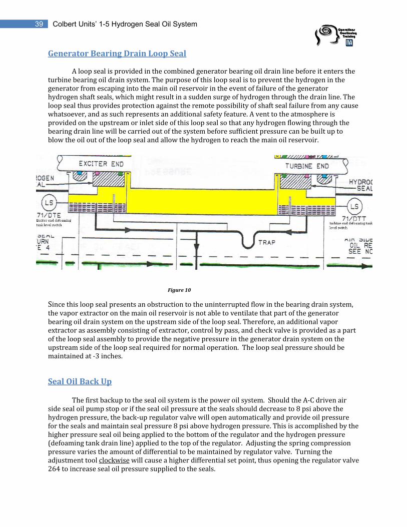
Generator Bearing Drain Loop Seal
A loop seal is provided in the combined generator bearing oil drain line before it enters the turbine bearing oil drain system. The purpose of this loop seal is to prevent the hydrogen in the generator from escaping into the main oil reservoir in the event of failure of the generator hydrogen shaft seals, which might result in a sudden surge of hydrogen through the drain line. The loop seal thus provides protection against the remote possibility of shaft seal failure from any cause whatsoever, and as such represents an additional safety feature. A vent to the atmosphere is provided on the upstream or inlet side of this loop seal so that any hydrogen flowing through the bearing drain line will be carried out of the system before sufficient pressure can be built up to blow the oil out of the loop seal and allow the hydrogen to reach the main oil reservoir.
Figure 10
Since this loop seal presents an obstruction to the uninterrupted flow in the bearing drain system, the vapor extractor on the main oil reservoir is not able to ventilate that part of the generator bearing oil drain system on the upstream side of the loop seal. Therefore, an additional vapor extractor as assembly consisting of extractor, control by pass, and check valve is provided as a part of the loop seal assembly to provide the negative pressure in the generator drain system on the upstream side of the loop seal required for normal operation. The loop seal pressure should be maintained at -3 inches.
Seal Oil Back Up The first backup to the seal oil system is the power oil system. Should the A-C driven air side seal oil pump stop or if the seal oil pressure at the seals should decrease to 8 psi above the hydrogen pressure, the back-up regulator valve will open automatically and provide oil pressure for the seals and maintain seal pressure 8 psi above hydrogen pressure. This is accomplished by the higher pressure seal oil being applied to the bottom of the regulator and the hydrogen pressure (defoaming tank drain line) applied to the top of the regulator. Adjusting the spring compression pressure varies the amount of differential to be maintained by regulator valve. Turning the adjustment tool clockwise will cause a higher differential set point, thus opening the regulator valve 264 to increase seal oil pressure supplied to the seals.

40 Colbert Units’ 1-5 Hydrogen Seal Oil System
Figure 11
The back-up seal oil pressure will be supplied from several sources; namely: The power oil pump system and the bearing oil system. When bearing oil flows to the seals through the seal oil back-up, the excess oil will overflow through the seal oil return line into the main bearing oil drain.

41 Colbert Units’ 1-5 Hydrogen Seal Oil System
Figure 12
The power oil pump(s) supply high pressure oil to the back-up regulator valve. Under the condition of a failed the A-C driven seal oil pump, would result in a decrease of differential pressure to a point below the 8 psi referred to above. When the air side seal oil pressure at the seals drops to 5 psi above the gas pressure, switch 59-2/ASOH will close and automatically start the D-C motor driven air side seal oil back-up pump, which will restore and maintain the seal oil pressure at the seals at 12 psi above the hydrogen pressure.
From Power Oil System
From Lube Oil
System

42 Colbert Units’ 1-5 Hydrogen Seal Oil System
Figure 13
When this pressure is restored differential pressure switch 59-1/ASOH will open, but the D-C motor driven air side seal oil back-up pump will continue to operate as it is held in by an interlock in the control, and can be stopped only by a pushbutton. The starting of this D-C driven back-up pump gives the alarms “Seal Oil Pressure Low” and, “Seal Oil Backup Pump Running”. When this occurs the A-C motor driven seal oil pump should be started if possible, or the hydrogen pressure in the machine should be decreased to 2 psi or less as the next back-up pressure is only 5 psi from the motor driven turning gear oil pumps. When the seal oil differential pressure across the air side seal oil pump decreases to 5 psi pressure switch 59-2/ASOH closes and starts the D-C Seal Oil Backup Pump.

43 Colbert Units’ 1-5 Hydrogen Seal Oil System
Review Questions
11) How is the oil level maintained in the defoaming tanks? A) Float valve in hydrogen side float chamber B) Differential Pressure Regulator 256 C) Standpipe over-flow connection in defoaming tank D) A level is not maintained in the defoaming tank 12) What annunciation is associated with the defoaming tanks?________________________________ 13) T F A trap is provided in the drain line from the defoaming tanks to prevent the difference in the blower pressure at the two ends of the generator from causing circulation of oil vapor through the generator. 14) List the pumps associated with U5 seal oil skid. _________________________________________________________________________________________________________ _________________________________________________________________________________________________________ 15) The Air Side Seal Oil Pump receives its suction from the ___________________________________. 16) How would you increase Air Side Seal Oil Pressure/Hydrogen pressure from 11 psi to 12 psi differential? A) Turn adjusting tool on regulator valve 256 clockwise B) Turn adjusting tool on regulator valve 256 counterclockwise C) Throttle down on hand control valve on pump discharge D) Differential pressure is not adjustable
17) How is Hydrogen Side Seal oil pressure maintained the same as Air Side Seal Oil pressure? _____________________________________________________________________________________________ 18) The purpose of the _________________ is to prevent the hydrogen in the generator from escaping into the main oil reservoir in the event of failure of the generator hydrogen shaft seals, which might result in a sudden surge of hydrogen through the drain line. 19) The Generator Bearing loop seal should be maintained at inches of negative pressure. 20) The seal oil back up regulator supply comes from what sources? ________________________________________________________________________________________________________ _________________________________________________________________________________________________________

44 Colbert Units’ 1-5 Hydrogen Seal Oil System
22) How would you increase Seal Oil Backup pressure regulator valve # 264 set point from 7 psi to 8 psi differential? A) Turn adjusting tool on regulator valve 264 clockwise B) Turn adjusting tool on regulator valve 264 counterclockwise C) Opening bypass valve # 266 around regulator D) Differential pressure is not adjustable 23) What will happen if the Air Side AC Seal Oil/Hydrogen differential pressure drops to 5 psi?_____________________________________________________________________________________________________________________________________________________________________________________________________________ 24) What device starts the DC Seal Oil Backup Pump?____________________________________________
Instrumentation/Indications
Most indications and controls for the seal oil system are provided locally on the skid. The local instrumentation is broken up into pressure switches, pressure gauges, and temperature indications.
Pressure Switches
Figure 14

45 Colbert Units’ 1-5 Hydrogen Seal Oil System
Pressure Gauges
Gauge Normal indication at 45 psi H2
Seal Oil Pressure Differential(Exciter End) 0 inch of water
Seal Oil Pressure Differential(Turbine End) 0 inch of water
Air Side Seal Oil Pressure Gauge 57 psi
Hydrogen Side Seal Oil Pressure Gauge 57 psi Seal Oil Pressure Turbine End (on generator apron)
57 psi
Seal Oil Pressure Exciter End (on generator apron)
57 psi
Figure 15

46 Colbert Units’ 1-5 Hydrogen Seal Oil System
Temperature Seal oil temperature is monitored locally from two temperature gauges mounted in the seal oil line on the discharge of the Hydrogen side (located near the coolers) and Air side raw water coolers (located near the hydrogen side drain regulating tank). Normal oil temperature is maintained at 110 -120 degrees F.
Figure 16
Air Side Seal Oil Temperature
Hydrogen Side Seal Oil Temperature

47 Colbert Units’ 1-5 Hydrogen Seal Oil System
Control Room Indications The seal oil systems alarms are reported to the Hydrogen Panel Annunciator on Panel E. If any of the alarms are brought in on the Hydrogen Panel Annunciator the “GEN A Aux Panel Alarm” or “GEN B Aux Panel Alarm” will illuminate and set off bell in control room. ASSO and HSSO temperatures from the outlet of the coolers, are read from a Yokogawa recorder on Panel F.
Vertical Board Gen A Aux Panel Alarm Gen B Aux Panel Alarm
Figure 17
Figure 18

48 Colbert Units’ 1-5 Hydrogen Seal Oil System
Hydrogen Panel Annunciator Hydrogen Purity High or Low Hydrogen Pressure High or Low Hydrogen Supply Pressure Low Water Detector High Hydrogen Temperature High Defoaming Tank Level High (59-DTE or 59-DTT) Generator Air Equivalent Diff. Pressure Air Side Seal Oil Pump Off (59-ASO) Seal Oil Pressure Low Hydrogen Side Level Low (59-HDR) Seal Oil Turbine Backup Pressure Low (59-SOB) Hydrogen Side Seal Oil Pump Off (59/HSO) Air Side Seal Oil Backup Pump Running (59-ASOB) Generator Dew Point Inlet Temp High Generator Dew Point Outlet Temp High Air Side Seal Oil Filter Diff. Pressure High (59-ASOF) Hydrogen Side Seal Oil Filter Diff. Pressure High (59-HSOF) Generator Condition Monitor Alarm
Figure 19

49 Colbert Units’ 1-5 Hydrogen Seal Oil System
Initiating Devices
The pressure switches on the seal oil system are differential type. If the differential pressure (63/HSO) across the hydrogen side pump or the differential pressure (63/ASO) across the air side pump decreases to a point indicating either pump is not running or if the differential pressure between the seal oil and the generator gas pressure (63-1/ASOH) decreases to 8 psi, then a regulating valve (264) will begin to open and supply the seals from power oil. If the differential between the seal oil and the generator gas (63-2/ASOH) continues to decrease to 5 psi, then the backup DC seal oil pump will start and restore the differential to 12 psi (normal).
There are also differential pressure switches (63/ASOF and 63/HSOF) on the seal oil filters to indicate increased pressure drop across the filters.
Each of these actions will bring in an alarm on the panel located South of the seal oil room in the basement. Any alarm on the seal oil or hydrogen system on this panel will annunciate in the control room on panel E: 5A GENERATOR AUXILIARY PANEL ABNORMAL or 5B GENERATOR AUXILIARY PANEL ABNORMAL.
Review Questions
25)”Seal Oil Turbine Backup Pressure Low” comes in at what pressure. A) 15 psi B) 60 psi C) 45 psi D) 70 psi 26) What brings in the annunciation “Hydrogen Side Seal Oil Pump Off”? _________________________________________________________________________________________________________ 27) What should the Local Air Side Seal Oil Pressure gauge be reading if Hydrogen pressure is at 45psi? ___________________________________ 28) What should the Local Hydrogen Side Seal Oil Pressure gauge be reading if Hydrogen pressure is at 45psi? __________________________ 29) What temperature is the hydrogen side and air side seal oil maintained? ________________ ____________________________________________________________________________

50 Colbert Units’ 1-5 Hydrogen Seal Oil System
Modes of Operations
Normal Operation COF.SOI.10.059.004.U5 provides initial alignment of seal oil skid. Once in service the system requires little operation other than routine shift monitoring.
Degraded Operation
It should be borne in mind that the amount of gas pressure that can be maintained in the generator depends not upon the pressure being developed by the source of seal oil pressure being supplied, but rather depends upon the pressure available from the next back-up source of seal oil pressure. With any of the following acting as the backup the generator can maintain 45 psi hydrogen pressure.
1. Power Oil System 2. DC Seal Oil Backup Pump
If the following pumps are providing backup protection hydrogen pressure must be reduced to 2 psi.
1. DC Seal Oil Backup Pump 2. Bearing Oil System
The generator may be operated hydrogen cooled with air side seal oil supplied by the seal
oil back-up system with no increase in hydrogen consumption.
The generator may also be operated hydrogen cooled if the hydrogen side seal oil pump is not operating. Under this condition of operation, seal oil from the air side feed groove will flow both directions along the shaft, providing the necessary lubrication and preventing the hydrogen from escaping from the generator. However, it will be necessary to add fresh hydrogen to maintain the required value of hydrogen purity in the generator, since the air side oil flowing into the hydrogen side of the seal rings will bring air and moisture into contact with the hydrogen inside the machine and will remove some of the hydrogen from the generator by absorption into the oil.
Review Questions
30) If the unit is offline and the seal oil pumps and the power oil pumps are tagged out, what is the maximum amount of hydrogen pressure in the generator? _____________________________________________________ 31) T F The generator may be operated hydrogen cooled if the hydrogen side seal oil pump is not operating. 32) (Unit is online) The AC Seal Oil pump is tagged out ; What is providing seal oil backup? What would need to happen if unit trips. __________________________________________________________________________________________________________________________________________________________________________________________________________________

51 Colbert Units’ 1-5 Hydrogen Seal Oil System
Electrical Distribution
There are six pumps associated with the seal oil system on U5, three for A generator and three for B generator. For each generator there is a hydrogen side pump, a primary air side pump, and a backup air side pump. The A hydrogen side pump and primary air side pump are fed from the 480v MCC board 5A which is fed from 4160v Unit board A through a 4160/480v step down transformer. The B pumps are fed similarly from MCC board 5B.
The ASSO, HSSO and DC Seal Oil Backup pumps are started locally at their respective hydrogen panel. Also, there are Reset/Stop LPB’s at the Seal Oil Skid.
Figure 20
ASSO Pump HSSO Pump

52 Colbert Units’ 1-5 Hydrogen Seal Oil System
Figure 21
The air side backup pumps are 250v DC. Pump A normal feed is from battery board 3 breaker #21, and the alternate feed is from battery board 2 breaker #23. Pump B normal feed is from battery board 3 breaker #22, and the alternate feed is from battery board 2 breaker #24. Starting of the DC motor is through a differential pressure switch when differential pressure drops to 5 psi. In the event that the normal 250v DC is lost, the manual throw over switch must be placed to the alternate source. Once the normal seal supply is restored, the DC Seal Oil Backup Pump must be stopped at the hydrogen panel on the South wall in the basement.
Review Questions
33) Electrical distribution to the seal oil pumps is from. A) 480V Unit Board B) 480V MCC Board C) 480V Pump Board D) None of the above 34) Can the Hydrogen Side Seal Oil Pump be out of service and seal oil pressure be maintained? If yes, explain what actions must be taken to ensure protection of the generator.______________________________________________________________________________________________________________________________________________________________________________________________________

53 Colbert Units’ 1-5 Hydrogen Seal Oil System
35) What is the electrical distribution source for the Seal Oil DC backup pump?_________________________________________________________________________________________________ _________________________________________________________________________________________________________ 36) If the normal DC source is lost to the DC Seal Oil Backup Pump, what action must be taken in thefield?_____________________________________________________________________________________ _________________________________________________________________________________________________________
Isolation Points
Electrical Isolation Points
D.C. Air Side Backup Seal Oil Pump 250 volt local disconnect A-C Air Side Seal Oil Pump 480v ACB
Hydrogen Side Seal Oil Pump 480v ACB
Mechanical Isolation Points
Seal Oil Backup Regulator inlet isolation valve HCV-59-265 Seal Oil Backup Regulator Bypass isolation valve HCV-59-266 Seal Oil Coolers raw cooling water inlet isolation root valve HCV-24-891, 24-890 Air Side Seal Oil Cooler raw cooling water outlet isolation valve HCV-24-903 Hydrogen Side Seal Oil Cooler raw cooling water outlet isolation valve HCV-24-902