code of practice for design, installation, … · for design, installation, commissioning &...
TRANSCRIPT

FIA COP for ASD's June , 2006
Issue 2 Page 1 of 72
Code of Practice for
Design, Installation, Commissioning
& Maintenance of
Aspirating Smoke Detector (ASD) Systems

FIA COP for ASD's June , 2006
Issue 2 Page 2 of 72
Fire Industry Association
Code of Practice for Design, Installation, Commissioning & Maintenance of
Aspirating Smoke Detector (ASD) Systems
This Code of Practice is intended as a general guidance and is not a substitute for detailed advice in specific circumstances. Although great care has been taken in the compilation and preparation of this publication to ensure accuracy, FIA cannot in any circumstances accept responsibility for errors, omissions or advice given or for any losses arising from reliance upon information contained in this publication.
Fire Industry Association THAMES HOUSE,
29 THAMES STREET, KINGSTON UPON THAMES,
SURREY, KT1 1PH Telephone: 020 8549 5855
Fax: 020 8547 1564 e-mail: [email protected]
Copyright : The contents of this code of practice are copyright of Fire Industry Association Limited. Reproduction or publication in whole or part Without prior permission is expressly forbidden.

Contents
1 SCOPE .............................................................................................................................. 7
2 NORMATIVE REFERENCES....................................................................................... 8
3 TERMS AND DEFINITIONS ........................................................................................ 8 3.1 ASPIRATING SMOKE DETECTOR (ASD) ................................................................................................ 8 3.2 ASD SYSTEM........................................................................................................................................ 8 3.3 BALANCING ORIFICE............................................................................................................................. 8 3.4 BALANCED SYSTEM.............................................................................................................................. 8 3.5 CAPILLARY PIPE ................................................................................................................................... 9 3.6 CIE - CONTROL AND INDICATION EQUIPMENT...................................................................................... 9 3.7 CONDITIONING...................................................................................................................................... 9 3.8 CONDITION WARNING (PRE-ALARM WARNING) .................................................................................. 9 3.9 CUMULATIVE EFFECT ........................................................................................................................... 9 3.10 EDP – ELECTRONIC DATA PROCESSING ............................................................................................... 9 3.11 EXTENDED SAMPLING PIPE................................................................................................................... 9 3.12 EXTENDED SAMPLING POINT ................................................................................................................ 9 3.13 MAIN PIPE............................................................................................................................................. 9 3.14 MAINTENANCE TEST POINT .................................................................................................................. 9 3.15 MAXIMUM TRANSPORT TIME.............................................................................................................. 10 3.16 PRIMARY SAMPLING SYSTEM ............................................................................................................. 10 3.17 PSU – POWER SUPPLY UNIT ............................................................................................................... 10 3.18 REFERENCING ..................................................................................................................................... 10 3.19 RESPONSE TIME .................................................................................................................................. 10 3.20 SAMPLING DEVICE.............................................................................................................................. 10 3.21 SAMPLING POINT ................................................................................................................................ 10 3.22 SECONDARY SAMPLING SYSTEM ........................................................................................................ 10 3.23 TEST POINT......................................................................................................................................... 10 3.24 TRANSPORT TIME ............................................................................................................................... 10 3.25 UNWANTED ALARMS .......................................................................................................................... 10
4 INTRODUCTION TO ASPIRATING SMOKE DETECTORS ............................... 11 4.1 REASON FOR USING ASD'S.................................................................................................................. 11
4.1.1 Very Early Warning....................................................................................................................... 11 4.1.2 Enhanced smoke sensitivity ........................................................................................................... 11 4.1.3 An Alternative to point or beam type smoke detectors .................................................................. 11
4.2 COMMON MOTIVATORS....................................................................................................................... 11 4.2.1 Extreme environments ................................................................................................................... 11 4.2.2 Restricted/difficult access.............................................................................................................. 12 4.2.3 Exceptional ceiling heights & heat barriers.................................................................................. 12 4.2.4 Aesthetics....................................................................................................................................... 12 4.2.5 Risk of mechanical damage........................................................................................................... 12 4.2.6 Anti-vandal systems....................................................................................................................... 12 4.2.7 Hazardous environments ............................................................................................................... 12
5 CATEGORIES OF SYSTEM ....................................................................................... 13 5.1 SENSITIVITY CLASSES:........................................................................................................................ 13 5.2 ASD SAMPLING TYPES/METHODS ....................................................................................................... 14
5.2.1 Primary Sampling ......................................................................................................................... 14 5.2.2 Secondary Sampling ...................................................................................................................... 14 5.2.3 Localized Sampling ....................................................................................................................... 15 5.2.4 In-cabinet Sampling ...................................................................................................................... 15 5.2.5 Duct Sampling ............................................................................................................................... 15
5.3 ROUTE TO COMPLIANCE (PRESCRIPTIVE OR PERFORMANCE BASED) ................................................... 16 5.4 SUMMARY AND EXAMPLES:................................................................................................................ 18

FIA COP for ASD's June , 2006
Issue 2 Page 4 of 72
6 EXCHANGE OF INFORMATION AND DEFINITION OF RESPONSIBILITIES19 6.1 EXCHANGE OF INFORMATION.............................................................................................................. 19 6.2 DEFINITIONS OF RESPONSIBILITIES...................................................................................................... 19 6.3 ACTION IN THE EVENT OF AN ALARM .................................................................................................. 20 6.4 CONSULTATIONS................................................................................................................................. 20 6.5 MULTI-OCCUPANCY BUILDINGS.......................................................................................................... 20
7 VARIATIONS OF RECOMMENDATIONS.............................................................. 21 7.1 GENERAL ............................................................................................................................................ 21
8 DESIGN CONSIDERATIONS ..................................................................................... 22 8.1 GENERAL ............................................................................................................................................ 22 8.2 ASD TECHNOLOGY............................................................................................................................. 22
8.2.1 The smoke and flow sensing elements.. ......................................................................................... 23 8.2.2 The method of aspiration............................................................................................................... 23 8.2.3 The sampling device. ..................................................................................................................... 23
8.3 SAMPLING POINT SPACING ................................................................................................................. 23 8.3.1 Horizontal spacing in normal environments ................................................................................. 24 8.3.2 Sampling in high airflow environments......................................................................................... 24 8.3.3 Spacing for Vertical sampling Systems ......................................................................................... 25 8.3.4 Ceilings and roofs using secondary sampling systems.................................................................. 26
8.4 REPORTING, SIGNALLING AND SYSTEM INTEGRATION......................................................................... 26 8.4.1 Standalone systems........................................................................................................................ 27 8.4.2 Integrated systems ......................................................................................................................... 27
8.5 FAULT MONITORING........................................................................................................................... 28 8.6 MAINTENANCE ................................................................................................................................... 29 8.7 POWER SUPPLIES ................................................................................................................................ 29 8.8 EXTINGUISHING SYSTEMS ................................................................................................................... 29
9 DESIGN TOOLS............................................................................................................ 31 9.1 CLOSED END PIPE:............................................................................................................................... 32 9.2 VENTED END CAP............................................................................................................................... 32 9.3 PIPE DESIGN CONSIDERATIONS........................................................................................................... 32
9.3.1 Primary Detection Sampling Systems............................................................................................ 32 9.3.2 Secondary Detection Sampling Systems ........................................................................................ 33 9.3.3 Maximum Permissible Transport Time ......................................................................................... 33 9.3.4 Balance.......................................................................................................................................... 34 9.3.5 Relative sensitivity......................................................................................................................... 34
9.4 RECOMMENDATIONS:.......................................................................................................................... 34 10 APPLICATIONS........................................................................................................ 36
10.1 ELECTRONIC DATA PROCESSING (EDP) AREAS.................................................................................. 36 10.2 WAREHOUSING ................................................................................................................................... 37 10.3 IN-CABINET DETECTION...................................................................................................................... 37 10.4 HERITAGE BUILDINGS......................................................................................................................... 38 10.5 HARSH ENVIRONMENTS...................................................................................................................... 38
10.5.1 Cold areas. ............................................................................................................................... 38 10.5.2 Wet areas .................................................................................................................................. 39 10.5.3 High Temperature areas........................................................................................................... 40 10.5.4 Dirty and Dusty areas............................................................................................................... 40 10.5.5 Potentially explosive environments .......................................................................................... 40
10.6 HVAC DUCT DETECTION ................................................................................................................... 41 11 PRODUCT STANDARDS & MARKING ............................................................... 42
12 LIMITATION OF FALSE ALARMS...................................................................... 43 12.1 UNWANTED ALARMS........................................................................................................................... 43
12.1.1 Alarm Thresholds ..................................................................................................................... 43

FIA COP for ASD's June , 2006
Issue 2 Page 5 of 72
12.1.2 Fault Logs................................................................................................................................. 43 12.1.3 Multiple alarm thresholds ........................................................................................................ 43 12.1.4 Referencing............................................................................................................................... 44 12.1.5 Alarm Delays ............................................................................................................................ 44 12.1.6 Day Night Setting...................................................................................................................... 44 12.1.7 Software Algorithms ................................................................................................................. 44 12.1.8 Filtering.................................................................................................................................... 44
12.2 EQUIPMENT ALARMS........................................................................................................................... 44 13 INSTALLATION ....................................................................................................... 45
13.1 SITING OF EQUIPMENT ........................................................................................................................ 45 13.2 ELECTRICAL INSTALLATION ............................................................................................................... 45 13.3 MECHANICAL INSTALLATION ............................................................................................................. 45
13.3.1 Pipework................................................................................................................................... 45 13.3.2 Sampling points ........................................................................................................................ 46
13.4 LABELLING REQUIREMENTS................................................................................................................ 46 13.5 INSPECTION......................................................................................................................................... 47
14 COMMISSIONING AND HANDOVER ................................................................. 48 14.1 COMMISSIONING TESTING................................................................................................................... 48 14.2 COMMISSIONING ................................................................................................................................. 48
14.2.1 Inspection of Installation .......................................................................................................... 48 14.2.2 Power up/Configuration ........................................................................................................... 49 14.2.3 Commissioning Tests ................................................................................................................ 49 14.2.4 Signalling.................................................................................................................................. 51 14.2.5 System Handover ...................................................................................................................... 51
15 MAINTENANCE ....................................................................................................... 52 15.1 FREQUENCY OF MAINTENANCE ........................................................................................................... 52 15.2 RECOMMENDATIONS FOR ROUTINE INSPECTION AND FUNCTIONAL TESTING....................................... 52
15.2.1 Routine Inspection .................................................................................................................... 52 15.2.2 Functional Tests ....................................................................................................................... 53
16 USER RESPONSIBILITIES..................................................................................... 54
APPENDIX A – ASD SYSTEM PERFORMANCE TESTS.............................................. 55
APPENDIX B - SMOKE PELLET PERFORMANCE TEST........................................... 56
APPENDIX C - PAPER BURN PERFORMANCE TEST................................................. 57
APPENDIX D - OVERHEATED ENAMEL WIRE PERFORMANCE TEST ............... 58
APPENDIX E –OVERHEATED PVC/LSF WIRE PERFORMANCE TESTS .............. 59
APPENDIX F – OVERHEATED RESISTOR PERFORMANCE TESTS ...................... 62
APPENDIX G - POLYURETHANE MAT PERFORMANCE TEST.............................. 63
APPENDIX H – POTASSIUM CHLORATE / LACTOSE PERFORMANCE TEST ... 64
APPENDIX I – EXAMPLE FORMS ................................................................................... 65 FIGURES

FIA COP for ASD's June , 2006
Issue 2 Page 6 of 72
FIGURE 1 - SINGLE PIPE ..........................................................................................................................................33 FIGURE 2 - 2 PIPE SYSTEM ......................................................................................................................................33 FIGURE 3 - 4 PIPE SYSTEM ......................................................................................................................................34 TABLES TABLE 1 - SAMPLING HOLE POSITIONS..................................................................................................................14 TABLE 2- SENSITIVITY CLASSES VS. DETECTION REQUIREMENTS........................................................................17 TABLE 3 - INSTALLATION HEIGHT..........................................................................................................................26

FIA COP for ASD's June , 2006
Issue 2 Page 7 of 72
1 Scope The Code of practice provides recommendations for the planning, design, installation, commission and maintenance of aspirating smoke detection systems. It identifies categories of ASD systems and typical applications where such systems can be used. It also provides specific design rules on common applications and guidance on good practice. A series of performance tests are provided and guidance on how and where they should be used. A number of forms are provided in the Appendices to be used as checklists to ensure that the correct information is transferred through each stage of the process (Planning-Design- Installations-Commissioning- Maintenance) This Code of Practice does not define the sampling device (e.g. pipe hole sizes or pipe diameters), which must be specified in-conjunction with the specific manufacturer’s design tools. This document supersedes the "Code of practice for Category 1 aspirating detection systems - British Fire Protection Systems Association 1996"

FIA COP for ASD's June , 2006
Issue 2 Page 8 of 72
2 Normative References
BS 5839-1: 2002 Fire detection and fire alarm systems for buildings —Part 1: Code of practice for system design, installation, commissioning
and maintenance
BS 6266: 2002 Code of practice for fire protection for electronic equipment installations
CEA 4022 12/1999 Title? EN 54-7:2001 Fire detection and fire alarm systems Part 7: Smoke detectors –
Point detectors using scattered light, transmitted light or ionization
prEN 54-20: 2004 Fire detection and fire alarm systems – Part 20: Aspirating smoke detectors
VdS 2095: 2001-3(05)
VdS-Richtlinien für automatische Brandmeldeanlagen – Planung und Eunbau
ADPAD R7 Règle d’installation. Detection automatique d’incendie EN54-2 :1997 Fire detection and fire alarm systems – Part 2 .Control and
indicating equipment EN54-4 :2001 Fire detection and fire alarm systems – Part 4. power supply
equipment
3 Terms and definitions For the purpose of this document the terms and definitions in BS EN ISO 13943 and the following apply.
3.1 Aspirating Smoke Detector (ASD) A smoke detector consisting of one or more smoke sensing elements, an aspirator, one or more flow sensors and necessary controls/electronics, typically housed in a single enclosure, forming the main part of an ASD system but excluding the sampling device
3.2 ASD System A smoke detection system, in which air and aerosols are drawn through a sampling device and carried to one or more smoke sensing elements by an integral aspirator (e.g. fan or pump) Note: Each smoke sensing element may contain more than one sensor exposed to the same smoke sample.
3.3 Balancing Orifice In pipework systems the system pipework may be balanced by an end of pipe orifice of a calculated size which is, in general, less than the bore of the sampling pipe.
3.4 Balanced System An ASD in which there is an equal air flow and thus equal detection sensitivity at each

FIA COP for ASD's June , 2006
Issue 2 Page 9 of 72
sampling point.
3.5 Capillary Pipe An extended sampling pipe where the diameter is significantly smaller than the main pipe.
3.6 CIE - Control and Indication Equipment In accordance with EN54-2
3.7 Conditioning The exposure of a specimen to environmental conditions in order to determine the effect of such conditions on the specimen.
3.8 Condition Warning (Pre-Alarm Warning) The status of an ASD reflecting a change of signal at the control equipment which is greater than the ambient non-fire state, and not exceeding the normal fire state.
3.9 Cumulative Effect Where combustion aerosols enter more than one sampling point, their combined effect results in the ASD being more responsive than if aerosols enter only one sample point.
3.10 EDP – Electronic Data Processing Machinery and equipment necessary to receive or transmit data, to process it and either to record or print the output results or to feed the output directly to controlled processes.
3.11 Extended Sampling Pipe A length of pipe with a diameter equal to or less than the main pipe; with a minimum diameter and length limited by the manufacturer's recommendations.
3.12 Extended Sampling Point A single sampling point which is extended from the main pipe by an extended sampling pipe or capillary pipe.
3.13 Main Pipe A length of pipe which, together with sampling holes makes up the most common form of sampling device.
3.14 Maintenance Test Point A test point, provided after the last sampling point, to test the integrity of concealed or inaccessible pipe work.

FIA COP for ASD's June , 2006
Issue 2 Page 10 of 72
3.15 Maximum Transport Time The maximum time in the ASD system for aerosols to transfer from the furthest sampling point to the smoke sensing element.
3.16 Primary Sampling System An ASD system utilizing the air flow created by the air conditioning and ventilation system to carry the sampled air to the sampling points.
3.17 PSU – Power Supply Unit In accordance with EN 54-4
3.18 Referencing A technique used to counteract the effects of external pollution into the protected area.
3.19 Response Time The time between the generation of combustion aerosols at their source and the indication of their presence at the ASD.
3.20 Sampling Device A component or series of components or dedicated device (e.g. a single sampling pipe, network of sampling pipes, dedicated duct probe or hood) which transfers samples of air to the ASD.
3.21 Sampling Point Any point at which an air sample is drawn into the sampling device
3.22 Secondary Sampling System
A system where the sampling points are sited and spaced as if they are point type smoke detectors
3.23 Test Point A sampling point which is clearly identified for test purposes and is normally the last sampling point on the main pipe or branch pipe.
3.24 Transport Time
The time for aerosols to transfer from a sampling point to the smoke sensing element.
3.25 Unwanted Alarms See BS 5839-1: 2002 – Clause 3.17

FIA COP for ASD's June , 2006
Issue 2 Page 11 of 72
4 Introduction to Aspirating Smoke detectors The use of ASD's have significantly increased since their introduction and incorporation into BS5839 Part 1:1988, BS6266: 1992, NFPA 72, NFPA 76 and the subsequent publication of the 1996 BFPSA Code of Practice for Category 1 Aspirating Systems. ASD's now provide the solution to a wide range of fire detection problems.
The ASD system is often an integral part of the overall fire detection & alarm system particularly when replacing point or beam type smoke detectors. When this is the case, the ASD system designer must still maintain compliance to National Standards, especially for fault monitoring, zoning, battery standby etc.
There are many reasons and motivators for using ASD's, as summarised in 4.2. is intended to describe some of the challenges of specific applications and practical guidance to engineer workable solutions.
4.1 Reason for using ASD's
The principal reasons for applying ASD's are:
4.1.1 Very Early Warning A warning of smoke (typically in an EDP environment with high airflows) before the point or beam type smoke detection systems can operate.
4.1.2 Enhanced smoke sensitivity For enhanced smoke sesitivity (e.g. to combat smoke dilution where the ceiling is higher than normal) or for an earlier than normal warning.
4.1.3 An Alternative to point or beam type smoke detectors As an alternative to point or beam type smoke detectors for a variety of reasons e.g. maintenance access, building deflection, dilution, and obstructions to line of sight.
4.2 Common motivators
There are many motivations for deploying an ASD system. The following list is intended to assist in the classification and therefore specification of ASD systems.
4.2.1 Extreme environments
Harsh environments (e.g. extreme temperature, humidity, contamination etc)

FIA COP for ASD's June , 2006
Issue 2 Page 12 of 72
4.2.2 Restricted/difficult access
Future access for maintenance will be difficult or even impossible after installation..
4.2.3 Exceptional ceiling heights & heat barriers
Stratification, dispersion and dilution issues are present as well as access restrictions.
4.2.4 Aesthetics
Architectural or aesthetic requirements preclude mounting services on the ceiling.
4.2.5 Risk of mechanical damage
Operational damage is anticipated (in racking & storage systems).
4.2.6 Anti-vandal systems
Vandalism may be an issue so therefore discreet detection is required.
4.2.7 Hazardous environments
The risk is hazardous e.g. Explosive, Chemical, Radioactive environments etc.

FIA COP for ASD's June , 2006
Issue 2 Page 13 of 72
5 Categories of system As described in the Section 4 there are many reasons for using ASD systems. The detection sensitivies of such systems are frequently tailored to the particular application to achieve the performance capability desired without being susceptible to unwanted alarms.
This section defines a category for an ASD system encompassing all the essential elements in such a way that any individual system can be described in a single unambiguous phrase. The category takes into account:
• Class of the detector (as defined in prEN 54-20) • Type or method of sampling (e.g. primary or secondary sampling) • Compliance route (either prescriptive or performance based) • Prime motivators for using an ASD system
Table 2 in this section is provided to assist in the correct specification of the ASD system to be deployed and relates to the performance tests presented in Appendix A. To illustrate the ASD category several typical examples are given in 5.4
5.1 Sensitivity Classes: For the purposes of categorisation there are considered to be 3 sensitivity classes which relate directly to those specific in prEN 54-20:2004 Note: The sensitivity class relates to the “ASD system” (see section 3.2) and includes any dilution due to the “sampling device”. It is not the sensitivity of the detector without dilution.
Class A - Very High Sensitivity
An ASD system with very high sensitivity that is capable of providing very early warning of a potential fire condition. Such systems are particularly relevant for high-risk areas where staged responses to the multistage alarm conditions are justified to ensure minimum down time of the protected area that may result from any fire related incident
Class B - Enhanced Sensitivity
An ASD system with enhanced sensitivity for applications where an additional degree of confidence is required for the protection of a particular risk. The enhanced capability of such systems is often required to compensate for other risk factors in the protected area such as unusually high ceilings or significant air flows.
Class C - Normal Sensitivity An ASD system designed to give equivalent performance to standard
point detection systems meeting the requirements of EN 54-7 For the nominal bands of sensitivity for these classes see Table 2.

FIA COP for ASD's June , 2006
Issue 2 Page 14 of 72
5.2 ASD Sampling types/methods For the purposes of categorization, there are considered to be five different approaches to sampling types of ASD.
5.2.1 Primary Sampling Primary Sampling is arranged to sample from specific locations in the protected area where smoke is most likely to travel / accumulate. Most typically this is at the air intake grilles of Air Handling Units (AHUs) or pressure relief vents (PRV), but sampling may be arranged wherever any smoke is likely to travel. This type of system is usually regarded as supplementary to other forms of detection where its response capability is dependant on external systems such as the air movement provided by AHUs. However, where such conditions exist it is generally acknowledged that ASD systems arranged for Primary Sampling provide the earliest possible warning of a fire condition. Given the fact that Primary Sampling is generally installed to provide early warning or to overcome the challenge of air movement in a particular area it is recommended that only Class A and B systems are used in this application.
5.2.2 Secondary Sampling Secondary Sampling is arranged such that the air sampling points are sited and spaced as an alternative to point type smoke detectors. Sampling holes are therefore positioned in accordance with prevailing National or International standards but it should be noted that these are minimum spacing requirements which are normally bettered when using ASD as a results of Performance Based Design. Some example standards are shown in Table 1.
Table 1 - Sampling Hole Positions
Sampling hole positioning in accordance with established standards for point detectors
Country Standard for normal environments
Standard to high risk environments
United Kingdom
BS5839-1: 2002 BS6266: 2002
Germany VdS 2095 VdS 2095 (appendixes) France R7 Rules - USA NFPA 72 NFPA 76
Where such systems are installed and intended to be in accordance with the appropriate standard, it is important to ensure that the installed performance of each hole (or group of holes if more than one hole is specified to be equivalent to a point detector), is equivalent to (or exceeds) the minimum performance requirements of a point detector.
The sensitivity of each individual air sampling point (assuming that all sampling points have been designed to provide a balanced system) can be estimated using a
FIA COP for ASD's June , 2006
Issue 2 Page 15 of 72
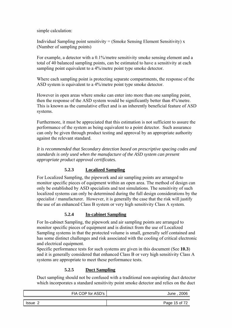
simple calculation: Individual Sampling point sensitivity = (Smoke Sensing Element Sensitivity) x (Number of sampling points) For example, a detector with a 0.1%/metre sensitivity smoke sensing element and a total of 40 balanced sampling points, can be estimated to have a sensitivity at each sampling point equivalent to a 4%/metre point type smoke detector. Where each sampling point is protecting separate compartments, the response of the ASD system is equivalent to a 4%/metre point type smoke detector. However in open areas where smoke can enter into more than one sampling point, then the response of the ASD system would be significantly better than 4%/metre. This is known as the cumulative effect and is an inherently beneficial feature of ASD systems.
Furthermore, it must be appreciated that this estimation is not sufficient to assure the performance of the system as being equivalent to a point detector. Such assurance can only be given through product testing and approval by an appropriate authority against the relevant standard.
It is recommended that Secondary detection based on prescriptive spacing codes and standards is only used when the manufacture of the ASD system can present appropriate product approval certificates.
5.2.3 Localized Sampling For Localized Sampling, the pipework and air sampling points are arranged to monitor specific pieces of equipment within an open area. The method of design can only be established by ASD specialists and test simulations. The sensitivity of such localized systems can only be determined during the full design considerations by the specialist / manufacturer. However, it is generally the case that the risk will justify the use of an enhanced Class B system or very high sensitivity Class A system.
5.2.4 In-cabinet Sampling
For In-cabinet Sampling, the pipework and air sampling points are arranged to monitor specific pieces of equipment and is distinct from the use of Localized Sampling systems in that the protected volume is small, generally self contained and has some distinct challenges and risk associated with the cooling of critical electronic and electrical equipment. Specific performance tests for such systems are given in this document (See 10.3) and it is generally considered that enhanced Class B or very high sensitivity Class A systems are appropriate to meet these performance tests.
5.2.5 Duct Sampling Duct sampling should not be confused with a traditional non-aspirating duct detector which incorporates a standard sensitivity point smoke detector and relies on the duct

FIA COP for ASD's June , 2006
Issue 2 Page 16 of 72
air flow to pass any smoke sample through the inlet probe, through the detector and out of the exhaust probe. Such a duct detector will not sample when there is no airflow in the duct. ASD systems can be used for duct sampling dependant on the risk and application. They do not rely on the duct air-flow to pass any smoke samples through the detector because of the integral aspirator or fan. Firstly the underlying reason for smoke detection in the duct should be clearly defined:
• Detect smoke in the duct in order to trigger a control system to prevent it being transferred through a building;
Or
• Special applications, where detection of the smoke in a duct is used to
indicate fire in the area from which the air is being extracted. In either case earlier warning using a higher sensitivity detector is possible using an ASD system and is often cited as a reason for its application as an alternative to traditional duct detectors.
In areas that are less than 100m2 (e.g. detention cells) duct sampling may be at a similar smoke sensitivity to replace point smoke detectors i.e. 4.0%/m obscuration. In larger areas the smoke sensitivity would have to be increased to cater for either the increased duct airflow or the larger risk area. Manufacturer’s recommendations should be sought to determine the optimum position in the duct for the intake & exhaust pipes and the maximum duct airspeeds (See 10.6 for specific application guidance) In any event when replacing point smoke detectors, the maximum floor area covered by one duct mounted ASD should not exceed 2000m2 or one smoke detection zone under BS 5839-1: 2002 Section 2:13.
5.3 Route to compliance (Prescriptive or Performance based) The decision as to whether performance tests should be conducted during commissioning depends on the classification of the ASD system being deployed. Generally, there is only one situation where a performance test can be omitted and that is when an approved ASD system is deployed with sampling hole spacing that falls within the full requirements of the relevant code e.g. BS 5839-1: 2002 and is fully compliant with the specific requirements of the product approval. This situation is highlighted in the table below. In all other situations it is recommended that a suitable performance test is specified and carried out during commissioning to verify the system. Refer to Section 14.

FIA COP for ASD's June , 2006
Issue 2 Page 17 of 72
Table 2- Sensitivity Classes vs. Detection requirements
Class (EN54-20)
Class A
Very High Sensitivity
Class B Enhanced Sensitivity
Class C Normal
Sensitivity Sensitivity
(% obscuration/m)
ASD Sampling Type:
Better than
0.8 % obs/m
Between
0.8%obs/m and 2%obs/m
Over 2%obs/m (still meeting
EN54-7)
Primary Detection: - sampling where smoke is likely to travel
Best Appropriate Not appropriate
E.G. BS 6266: 2002 Refer Section (BS 6266- 4.5) Risk Assessment Categories
For Risks D & E
For Risk D
Not appropriate
Secondary Detection: - positioning sampling holes according to the codes for point detectors
For Early warning
applications
For challenging applications
Appropriate
E.G. BS 5839-1: 2002 For applications where risks
require early warning
For applications that marginally exceed
recommendations of BS 5839-1
Appropriate
E.G. BS 6266: 2002 Refer Section (BS 6266- 4.5) Risk Assessment Categories
For Risks D & E
For Risk D
Appropriate for Risks A-C only
Localized sampling: - custom protection of specific equipment
Appropriate for high risk
Appropriate for low risk
Not appropriate
In-cabinet sampling: - Localized sampling:
Appropriate for high risk
Appropriate for low risk
Not appropriate
Duct sampling: -
Appropriate for high risk
Appropriate for low risk
Not appropriate
Other motivators (see Section 4.2) • extreme environments • restricted/difficult access • exceptional ceiling height • heat barriers
• aesthetics • risk of mechanical damage • anti-vandal systems • hazardous environment
Using this table it is possible to classify all ASD systems. Key - shaded block indicates where prescriptive design may be used.
FIA COP for ASD's June , 2006
Issue 2 Page 18 of 72
5.4 Summary and Examples: In summary the ASD category encompasses:
• Detector Class A, B or C • Type/method of sampling – Primary, Secondary, Localised, In-cabinet or
Duct • Primary Motivation – to clearly identify the principal reason for using ASD • Requirements for compliance – by referring to prescriptive standards or a
performance based test.
These categories are illustrated by the following examples:
• Class A detector providing Primary sampling within high airflow area to BS 6266 spacing
• Class A detector providing Primary sampling for Very Early Warning to meet Test E.2
• Class B detector providing Localised sampling of equipment X to BS 6266 spacing
• Class C detector providing Secondary sampling for an area with restricted access to BS 5839 spacing.
• Class C system providing Duct sampling of a return air duct as part of a smoke containment system to detect a 7-9g pellet according to appendix A

FIA COP for ASD's June , 2006
Issue 2 Page 19 of 72
6 Exchange of information and definition of responsibilities
6.1 Exchange of information The user or purchaser of the ASD system, or an appointed representative, should ensure that there is consultation at, or prior to, the system design stage with all relevant interested parties. The responsibility for each of the following stages should be clearly defined:
• System Planning • System Design • Installation • Commissioning • Maintenance
The information relevant to each of the stages shall be clearly recorded. Example forms are in Appendix H reflecting the guidance in this Code of Practice. The system planning stage should provide a clear indication of the ASD system category and include details of the environmental conditions to be anticipated, proposed processes and the system performance test proving requirements. On the basis of these consultations, documents should be prepared; these may include but are not limited to:
• Details of the installation proposed, including ASD system category. • Any special accommodation required for the equipment. • Any special structural provision required for the equipment or it's
associated pipework such as chases, ducts or supports. • Any link to the main fire alarm system or any other interface with the
“house” fire detection and alarm system, equipment such as automatic extinguishing systems, air handling units or building management systems.
• Actions in the event of an alarm. • Any environmental conditions and processes which may affect detection
or have the potential for false alarms • Any functional/performance tests for the system. • Any future maintenance access requirements.
6.2 Definitions of responsibilities It is desirable that, at the contract stage, one organization should be designated to take overall responsibility for the performance of the ASD system, and that responsibility is clearly defined in the documentation. Where an ASD system is to be interfaced with another system that is the responsibility of another organization, the responsibility of each organization should be clearly defined and documented. Consideration should be given at the contract stage to ensure that the continued support, corrections or modifications throughout the expected life of the system are subject to the initial design criteria.
FIA COP for ASD's June , 2006
Issue 2 Page 20 of 72
Care must be taken by the user or purchaser to monitor for any changes at the location that could adversely effect the ASD system operation as identified by the manufacturer / specialist.
6.3 Action in the event of an alarm To a large extent the design of the fire alarm system will depend on the actions required after the alarm has been given. An ASD system with multiple alarm levels may be required to provide a different action at each level. It is thus essential these actions are pre-planned and the subject of early discussions. See Section 12.
6.4 Consultations The interested parties who should be additionally consulted on behalf of the user or occupier may include the following:
• The manufacturer of the ASD system • The supplier of any 3rd party equipment that the ASD system reports to. • The building services manager/consultant. • The heating and ventilation design contractor.
6.5 Multi-occupancy buildings If the building is under the control of more than one occupant then any new processes or changes to the building structure / air movement within one occupancy may adversely affect the operation of any ASD system installed elsewhere in the building. It is important that consultations should take place with those interested parties early in the planning stage of any ASD system and during the whole life of the system.

FIA COP for ASD's June , 2006
Issue 2 Page 21 of 72
7 Variations of recommendations
7.1 General
This document is a code of practice and, as such, its contents take the form of recommendations, rather than requirements. The recommendations are primarily based on recognised good practice in the design, installation, commissioning and maintenance of ASD systems. In certain circumstances variations from the recommendations may be necessary, even though, in general, the user, purchaser, enforcing authority or insurer requires quite strict compliance with this code of practice. These variations refer to aspects of the design that were appropriate and intentional, albeit not compliant with one or more recommendations of the code of practice. It does not, however, imply that the designer or installer has freedom to ignore the recommendations of this code of practice under circumstances in which a user, purchaser, enforcing authority or insurer seeks compliance with it. Variations always need to be the subject of specific agreement amongst all interested parties and need to be clearly identified in all relevant system documentation.

FIA COP for ASD's June , 2006
Issue 2 Page 22 of 72
8 Design Considerations
When designing ASD systems there are two main aspects to the design – the design of the ASD system itself (including the sampling device) and the operation/function of ASD system in the context of a reporting/response system that is often (but not always) an integral part of the overall fire detection & alarm system
8.1 General When designing ASD systems to provide smoke detection in accordance with National installation guidelines, the zoning requirements must be followed (e.g Section 13 BS 5839-1: 2002). ASD systems typically provide alarm indication relating to the general area covered by the sampling device. However, some ASD systems can be designed or configured to give an indication of the location of the relevant sampling point or group of sampling points. When a warning is given by the ASD system there should be no confusion about the zone from which it was received. To facilitate responses provided by persons, the zonal information should be such that the source of the problem can be rapidly located. Under normal circumstances a single aspirating detector should cover an area not exceeding a maximum area of a detection zone (nominally 2000m2 BS 5839-1) this does not preclude the aspirating detector to cover multiple detection zones within a single evacuation area. Failure of any single aspirator/fan or other critical component within an ASD system shall not remove protection from an area greater than 2000m2.
When operating as a high or enhanced sensitivity system, the source of the alarm may not be readily visible, leading to an erroneous conclusion that the alarm is 'false'. Special training may be required to acquaint security personnel of the abilities of these systems to detect combustion aerosols at an early stage, prior to there being a visible fire condition. Where aspirating detection systems are used, especially when monitoring supply and extract ducts, great care must be taken as such systems are likely to be influenced by air movement from large areas within a building, and may therefore not be confined to the definition of a detection zone as specified in BS 5839. Consideration should be given to monitoring branch ductwork from limited parts of the building and not the main return ducts or plenum.
8.2 ASD Technology.
Aspirating smoke detectors commonly incorporate a sensor of much higher sensitivity than that used in a point type smoke detector conforming to EN 54-7, and respond to much lower levels of products of combustion, or even particles produced before full combustion occurs.
ASD systems rely on three main areas of technology:

FIA COP for ASD's June , 2006
Issue 2 Page 23 of 72
• The smoke and flow sensing element(s) • The air mover such as a fan or aspirator; • The sampling device or pipework system between the area to be
protected and the sensors.
8.2.1 The smoke and flow sensing elements.. ASD smoke sensors use various technologies to measure the levels of combustion products in air passing through a sensor chamber. Some ASDs use sensitive versions of the technologies used in conventional ionisation and optical scatter type smoke detectors. Another type of ASD uses a light scattering technique, while others use focused laser beams and cloud chamber to determine the level of combustion products within an air sample. Similarly ASD flow sensors are based on a number of different technologies. Manufacturer’s literature explains the sensor technology they use together with the particular benefits as applied to particular applications.
8.2.2 The method of aspiration. The common method of aspirating the detector is by the use of a pump, fan or aspirator sited close to the sensor (often in the same enclosure). This causes the air (and combustion products) to flow through the sampling device to the ASD and then presents all or a proportion of this sampled air to flow through the sensor(s).
8.2.3 The sampling device. The aspirator draws air into a number of sampling points in the area to be protected (typically through holes in a pipework system). The correct design of the pipework system is essential to ensure that the air and combustion products are efficiently transport from the protected area to the sensor. Manufacturers’ provide design rules or design software, which are used to ensure suitable design of the pipework systems.
8.2.3.1 Multi-channel Detectors.
Some ASD systems are able to identify the individual sampling pipe generating an alarm condition, either by incorporating individual detectors for each sampling pipe or by sampling from individual pipes. In the latter case it is generally the case that sampling is arranged from all pipes with the scan sequence being initialised when smoke is detected as opposed to constant sequential sampling. The important factors to consider when applying these type of detectors are: 1. That the detector is approved and has been type tested to demonstrate that the
first alarm is declared within the times allowed in the type testing standards. 2. Additionally, that after the signalling of the first alarm, no pipe/channel is left
un-sampled for a period greater than 3 minutes. 3. That all areas protected are within a single evacuation area.
8.3 Sampling Point Spacing As an underlying principal, sampling points need to be positioned where smoke is

FIA COP for ASD's June , 2006
Issue 2 Page 24 of 72
expected to travel to.
8.3.1 Horizontal spacing in normal environments For prescriptive based designs (see 5.3), the requirements for national standards should be followed. Specifically the spacing of the sampling points should follow the recommendations for the spacing and positioning of smoke detectors. Such standards generally specify the area (or radius) of coverage for individual points depending on particular building conditions such as ceiling height, structural beams and pitched roofs. (e.g. BS 5839-1: 2002 Section 2:22).
For performance based design the prescriptive standards provide a very good foundation as a minimum requirements which can be enhanced by taking into account other factors identified during the risk assessment or site survey (such as air flows and obstacles). Often the performance of the system is verified by an agreed test.
8.3.2 Sampling in high airflow environments Protection of high air-flow environments is a particular application for ASD systems and the following sections provide insight into how such areas are protected.
8.3.2.1 Primary sampling considerations
Generally the earliest warning of a fire event in such environments is provided by primary sampling, where sampling points cover AHU return grilles. For primary sampling the following design points must take into consideration:
a. The full air intake grille should be adequately covered by a number of
sampling points. b. It is recommended that each sample point shall have a maximum area
coverage of 0.4m2 of the air grille. Note: typically 3 or more sampling holes are used to cover a single air intake.
c. The velocity of the airflow into the grille should be less than the manufacturers recommended limits – typically 4-6m/s. Where larger airflows are encountered special arrangements may be necessary such as positioning the pipe away from the grille using stand-off brackets.
d. It is generally the case that airflows into the grille follow the louvers (where fitted) the pipe should be positioned in the main air-stream.
e. Sample holes are typically positioned at an angle of 30-60o off centre, into the airflow.
f. Maintenance access to the air-handling unit should not be restricted by the sampling pipe. Convenient removal of the pipe should be accommodated.
g. Internal mounting of the pipe is sometimes desirable but require special consideration due to the internal operation of the air-handling unit (internal dampers and louvers) and the increased negative pressures relative to the pressured inform of the air return grille.
When mounting the sampling pipe it is generally recommended that the samples are taken upstream of any filtration to avoid the high negative pressures and the

FIA COP for ASD's June , 2006
Issue 2 Page 25 of 72
possibility of the filters removing smoke before it reaches the ASD system. See Section 10.1 (EDP) and Section 10.6 (Ducts).
8.3.2.2 Secondary detection hole spacing in EDP/High Airflow environments
To combat the effects of high airflow and subsequent smoke dilution, prescriptive design standards such as BS 6266: 2002 Table A.1 specify closer spacing of point detectors. These spacing rules are specifically intended for point detectors and may therefore be used where the ASD is being installed to meet the prescriptive design and each sampling hole has equivalent sensitivity to a standard point detector. However, in many cases these closer spacing requirements are not directly applicable to ASD and may be modified as follows.
a. Where Primary Sampling is installed which meets the performance
requirement of test Appendix E.2 and is interlinked to switch off the Air Handling Units in the event of an alarm, then a Class A secondary detection system can be considered to operate in still air (i.e. be designed to normal BS 5839-1 spacing).
b. Where Primary Sampling is installed which meets the performance requirement of test Appendix E.2 and which is not interlinked to the air handling units, the sampling point spacing of the secondary sampling system may be based on a coverage of 25m2 per point (see BS 6266: 2002 table A1) even in the floor and ceiling voids with high air velocities.
c. Where the ASD system is installed in return air plenum spaces (e.g. floor and ceiling voids with high air velocities) and the direction of the prevailing air flow is known, the ASD system may be specifically designed to take advantage of the cumulative effect – for example by relaxing the point spacing along the streamlines in favour of a denser spacing across the streamlines. In this case the sampling point spacing of the ASD system may be relaxed to the maximum spacing of 25m2 coverage per point (see BS 6266: 2002 table A.1). Such an approach results in rectangular areas of coverage.
It should be noted that for Category D and E risks under BS 6266:2002 an ASD System capable of meeting tests Appendix E.1 or E.2 is considered to be mandatory. It is also advisory for Category C risks particularly where airflows are counter-directional to the natural buoyancy of smoke.
8.3.3 Spacing for Vertical sampling Systems To combat expected stratification caused by heat barriers (see BS 5839-1: 2002 Section 2:22.for an explanation of stratification), ASD systems can be engineered to provide three dimensional volume protection. The pipework and air sampling points should be arranged to provide sampling in addition to the top-level horizontal plane (near the ceiling). This can be achieved by; vertical pipe runs, horizontal pipe runs at different heights, or individual drop pipe or capillaries from the ceiling runs. It is recommended that for comprehensive coverage, sampling points are introduced appearing at 3.0-8.0m intervals in the vertical plane (or 2oC increments of ambient

FIA COP for ASD's June , 2006
Issue 2 Page 26 of 72
temperature rising through the building if this is known). Vertical pipes should be carefully considered for the extent of coverage in the horizontal plane. It is possible to install vertical air sampling systems with sampling points arranged at regular intervals within vertical shafts and ducts to give enhanced detection to particular risks or overcome maintenance and access restrictions.
8.3.4 Ceilings and roofs using secondary sampling systems
Most national standards prescribe maximum ceiling heights for standard point detectors. Table 3 - Installation Height shows the limits of ceiling heights according to BS 5839-1: 2002 for normal sensitivity system and has additional rows to include the enhanced and very high sensitivity response requirements. It provides prescriptive guidance for the protection of higher ceiling heights.
However, the maximum ceiling heights in Table 3 - Installation Height are generally considered to be conservative for ASD systems and there is considerable evidence that satisfactory systems can be (and have been) installed covering higher ceiling heights. This is largely due to the cumulative effect. A design for an ASD system covering situations outside of BS 5839 -1: 2002 would be subject to an agreed variation. In all situations where a variation exists the risk should be assessed and performance tests considered to verify the system response.
Table 3 - Installation Height
Sensitivity Ceiling Height (m) 10% Ceiling Height (m)
Response required
ASD system used (Class)
General Limits
Rapid Attendance
General Limits
Rapid Attendance
Normal C 10.50 15.00 12.50 18.00 Normal B 12.00 17.00 14.00 21.00
Normal A 15.00 21.00 18.00 26.00
Enhanced B 8.00 10.00 9.00 11.00 Enhanced A 10.50 15.00 12.50 18.00 Very High A 4.00 6.00 5.00 7.00
The first column gives the desired response. For example, a normal response as per an EN 54-7 detector or an enhanced response from a Class B ASD system. The second column gives the class of ASD system installed. Columns 3&4 specify the maximum ceiling heights depending on the availability of rapid attendance (5 minutes) by the fire services. The final two columns allow for small section of ceiling (up to 10% by area) to exceed the limits given in columns 3&4 up to a defined maximum height.
8.4 Reporting, signalling and system integration This section deals with the operation/function of ASD system in the context of it being

FIA COP for ASD's June , 2006
Issue 2 Page 27 of 72
part of a reporting/response system which is often (but not always) an integral part of the overall fire detection & alarm system.
8.4.1 Standalone systems Where the ASD does not report into a CIE then it is considered to be a stand-alone system. In this case it may be connected to other equipment directly to perform certain actions under different conditions – such as a BMS system or automatic shutdown of process plant. In such cases the recommendations for integrated systems (below) should be considered in association with the risk and intended operation.
8.4.2 Integrated systems
8.4.2.1 Visual alarm signals
A clearly identified Fire signal shall be transmitted to the CIE and clearly indicated at the ASD system itself as a red indicator. The alarm condition shall be latched at the CIE until reset. Generally the local indication is also latched until reset from the CIE or reset locally at the ASD system. As an aspirating system can provide a number of condition warnings that are not to be treated as fire warnings, these visual alarm signals, clearly distinguishable from any other devices used on the premises, may be utilised to draw attention to the need to investigate the condition. The condition warnings may also cause an audible signal at the CIE, which should give a distinctive sound, which is different to the sound given to indicate a fire condition.
8.4.2.2 Multiple alarm thresholds
In certain premises utilising an ASD, which is integrated within a Fire Alarm System, it may be desirable to notify limited staff within special areas for the need to investigate a potential alarm. Three stages of alarm could be:
• First stage raising a local signal only for personnel working in an area to investigate.
• Second stage raising a pre-alarm condition at the CIE, which alerts security personnel to investigate.
• Third stage “Fire” alarm raising a fire condition at the CIE to initiate evacuation procedures.
In some systems a fourth stage alarm is available which may be interfaced into an automatic extinguishing system. For more detail see 8.7. Clearly the intent of each alarm stage must be carefully matched to the sensitivity (response threshold) and building operation.
8.4.2.3 System Interfacing
When the ASD system is interfaced to a CIE, the interfacing can either be through relay contacts (direct to a dedicated zone input or direct to an interface module) or

FIA COP for ASD's June , 2006
Issue 2 Page 28 of 72
through a systems protocol interface compatible with the control system. Any cables that are not within the enclosure should be monitored for open or short circuit faults.
8.4.2.4 Networking
Many ASD systems support networking of individual detectors to allow for remote display, signalling, reference detection, maintenance and interrogation. Such networking / remote capabilities are particularly useful for detectors that are located in remote or inaccessible locations such as roof and floor voids or those installed on remote sites such as pumping stations or telecommunication facilities. Where remote access is provided – either on the same site or from remote sites via modem (or similar) - it is essential that the appropriate access levels are maintained. For example any changes to the detector settings should only be possible through access level 3 (as defined in EN 54-2).
Such networks may also be used to transmit the primary fire signals to the CIE. For example, by providing relays local to the CIE. The integrity requirements of the network depend on the intended use – fundamentally when it forms part of the primary reporting path to the CIE, the standards relating to communication of fire alarm signals must be adhered to. However, where the communication over the said network is only for information additional to the primary alarm and fault signals the integrity requirements of the network may be relaxed.
In the UK, BS 5839-1: 2002 12.2.2 c) stipulates that a single communication fault should not result is a loss of more than 2000m². Due to the large area coverage of a single ASD detector it is generally the case that each covers a separate zone. Therefore, it is essential that any fault on the ASD communication network should not impair the communication from more than one ASD detector. Such communication faults may result from the loss of a detector, display or other device, or from a short, partial short or open circuit on any one link in the network. Careful consideration should be given to the latter and confirmation sought from the manufacturer on the ability of their network to continue communicating the primary alarm information in the event of a single fault. In addition BS 5839-1: 2002 12.2.2 d) stipulates that two simultaneous communication faults should not result in the loss of coverage of an area > 10,000m². Special consideration must therefore be given to ASD communication networks, which cover areas greater than 10,000m² and redundant reporting paths will be needed to meet this requirement. Similar requirements prevail in other European territories and reference should be made to the appropriate standards. For example, European Technical Specification CEN/TS 54-14.
8.5 Fault Monitoring The ASD should provide fault monitoring for airflow, detector removal/isolation,

FIA COP for ASD's June , 2006
Issue 2 Page 29 of 72
power supply fault and battery disconnection fault etc. The faults must be indicated on the CIE and national standards may also require local fault indication. Where the ASD is connected to a CIE the signal cabling should be monitored to the relevant national standards i.e. for open and short circuit fault conditions.
8.6 Maintenance Maintenance requirements should be considered during system design. In particular the recommended maintenance period and techniques should be defined. If performance parameters (such as air flow and transport time) are used to confirm system performance during maintenance, appropriate deviation limits should be defined. Typical examples might be:
• Airflow reading during maintenance should be confirmed as ± 20% of the values measured at commissioning
• Measurements of transport time from the furthest hole during maintenance should be confirmed to be within + 15% or + 3 seconds , which ever is the greater, of the same measurement taken at commissioning.
8.7 Power Supplies Within Europe the power for the ASD shall be supplied by a power supply unit (PSU) complying with EN 54-4. In other territories, appropriate international standards should be used. The PSU shall be installed in accordance with local wiring regulations. In the UK it shall be installed to meet the requirements BS 5839-1. The PSU may be integral or separate from the ASD. Where the PSU is separate from the ASD consideration must be given to the fault tolerance of the wiring particularly where the PSU provides power to more than one ASD. In this case a single fault should not disable protection in excess of that allowed by the prevailing standards. In the case of BS 5839-1: 2002 a single fault (open or short circuit) should not disable protection within an area greater than 2000m².
PSU faults may be transmitted direct to the CIE or via the ASD system.
The PSU shall be capable of supplying the maximum alarm load for the ASD system when in either normal or standby conditions. Where the ASD is installed as an essential element of the house fire alarm system the standby periods should the same as the house fire alarm system.
8.8 Extinguishing systems It is possible to use ASD to provide part or all of the smoke detection in areas where automatic extinguishing may be released to suppress fires. Usually this includes coincidence detection to avoid false operation and extinguishant release (see BS 6266:2002 clause 7.2.2.5 and BS 7273-1 or relevant national standards.)

FIA COP for ASD's June , 2006
Issue 2 Page 30 of 72
There are many advantages to incorporating ASD into Automatic extinguishing systems. However the following points should be considered:
• The high sensitivity alarms thresholds available on Class A and Class B
systems often provide early warning capability to avoid unwanted suppression release. However, they are not normally used for BOTH inputs to a co-incident extinguishing system.
• The high sensitivity alarm thresholds available on Class A and Class B systems
may be used as one input to a co-incident extinguishing system (with the second input provided by a normal sensitivity ASD or point detection system) where early indication of a possible suppression release is desirable.
• The normal sensitivity alarm thresholds available on Class C systems are fully
compatible with extinguishing systems and may be used as one or both inputs to a co-incident system.
• When using a Class C ASD system consideration should be given to the
cumulative effect and it is considered prudent that a single zone is limited to a maximum of 10 “normal sensitivity” holes or a specific suppression output is used which takes account of smoke entering more than one hole.
• Using multiple alarm thresholds based on the signal from a single ASD sensing
element is not considered to provide co-incident detection but may be relevant in specific applications where the consequences of unnecessary suppression release are minimal.

FIA COP for ASD's June , 2006
Issue 2 Page 31 of 72
9 Design Tools The design of the sampling device is critical to the performance of the ASD system. ASD systems draw samples through multiple sampling holes. The sensitivity of each hole is dependant on the amount of air entering each hole relative to the total flow through the detector (and of course its sensitivity). Generally the objective is to have equal amount of air entering each hole so that the system is “balanced”. However, practical considerations such as the range of drill diameters available mean that some compromises must be made. It is essential that the manufacturer of the ASD system provides a design methodology to ensure that the design of the system meets the performance requirements. This is achieved through the application of design rules, tables and/or software supplied by the ASD manufacturer. On no account should the design tool/methodology from one manufacturer be used to design the sampling arrangement and/or predict the system performance of an ASD system supplied by another manufacturer because the individual characteristics of each system are NOT identical. In essence, the design tools may be prescriptive – giving design solutions (e.g. hole sizes) based on pre-determined performance goals or may be descriptive – predicting the performance of the system (e.g. transport time, hole sensitivity etc) based on a given design arrangement. Generally they have an element of both but as with all design tools, it is important that the engineer is fully trained and competent to use the tools and understands the results presented. Irrespective of the technique used to calculate the system design, the design tools will require a number of input parameters to be specified. These parameters will provide predictions of the performance/capability that can be measured to verify the installed system. - See Commissioning Section 14. Details of the design input parameters and output predictions are specific to individual design tools but may include the following. Design Input parameters
• Area to be covered • Sampling point positions • Pipe configuration • Pipe sizes • Temperature • Atmospheric/Differential Pressures • Airflows • Sensitivity selection • Transport Time

FIA COP for ASD's June , 2006
Issue 2 Page 32 of 72
Design Output predictions • Transport Time • Sampling Hole Relative Sensitivity • Sampling point sizes • Pipe sizes • Airflows/Balance • Suction Pressure
Some of the inputs/outputs may be reversed depending upon the design tool used. Generally the better the information that is entered into the design tool the better will be the prediction that the design tool will provide. One of the major benefits of ASD systems is the ability to tailor the sampling pipe design to the specific requirements of the application. However, there is a trade off which needs to be appreciated/understood. This is best illustrated by outlining the two fundamental approaches to pipe-work design; often referred to as closed-end pipe and open-end pipe:
9.1 Closed end pipe: In closed ended pipe-work a balanced system is achieved through sampling points of various sizes; in this case the furthest sampling points are sized in relation to the remaining points (i.e. they are larger to compensate for the lower suction towards the end of the pipe).
9.2 Vented End Cap Vented-end pipe networks reduce transport time by arranging for the last hole (usually in the end cap) to be larger than the rest – accepting the compromise that this may result in a particularly sensitive last hole. This arrangement allows single size holes to be used, while maintaining acceptable balance.
Note: When ASD systems were first introduced, open-ended pipe systems (no end cap) were installed. This practice in not currently recommended by any of the major ASD manufacturers’ because the air would be drawn from the open end rather than the sampling points. Such systems are not recommended.
9.3 Pipe Design Considerations
• Primary Detection • Secondary Detection • Maximum Transport Time • Balance • Relative Sensitivity
9.3.1 Primary Detection Sampling Systems Are usually arranged to monitor the flow of air movement by the use of pipework

FIA COP for ASD's June , 2006
Issue 2 Page 33 of 72
and air sampling points mounted directly in the airflow. This type of system is usually regarded as supplementary to other forms of detection due to its limited response capability once the air movement ceases. In such a system when monitoring a single point of supply or extract, its system sensitivity may be directly related as equal to the sensitivity of the central detector due to the cumulative effect. In the case of a system monitoring more than one point of supply / extract then the system sensitivity will only be determined in discussions with the manufacturer or his representative.
9.3.2 Secondary Detection Sampling Systems Are arranged such that the air sampling points are sited and spaced as if they are point type smoke detectors. They can be positioned to satisfy BS 5839-1 and BS 6266 requirements when the calculated relative sensitivity per air sampling hole equates to a point detector. See Relative Sensitivity (9.3.5).
9.3.3 Maximum Permissible Transport Time The time taken for a system to transport a sample from a protected area should not exceed 120 seconds (2 minutes). Transport times in excess of this must be the subject of a variation - see section 7. Shorter maximum transport times may be desirable in certain applications and should be specified as part of the risk assessment. For example, Class A ASD systems are generally designed with transport times of less than 60 seconds. Maximum transport time can be directly affected by the installed sample pipe design, see Figure 1to Figure 3. The 4-branch design will provide the shortest transport time (Figure 3 - Four branch system).
Figure 1 - Single branch system

FIA COP for ASD's June , 2006
Issue 2 Page 34 of 72
Figure 2 - Two branch system
Figure 3 - Four branch system
9.3.4 Balance Balance is generally expressed as a percentage. For an exact definition refer to the manufacturers as there is no universal definition. However, if all the sample points have the same amount of air entering each sample hole then this is invariably described as a system with 100% balance.
9.3.5 Relative sensitivity The relative sensitivity of each air sampling hole (assuming that all sampling points have been calculated for an equivalent sensitivity i.e. 100% balance) can be calculated as a simple function of the detector sensitivity and the number of sample points. For example a 0.1% high sensitivity detection device connected to pipe-work containing 40 equivalent air sampling points can be regarded as a 4%/metre system which can be considered as a Class C sensitivity system. Unless otherwise stated in a manufacturer’s approval documentation a figure of better than 5%/m sensitivity per hole may be applied.
9.4 Recommendations:
The design methodology for the ASD system should be understood and in full

FIA COP for ASD's June , 2006
Issue 2 Page 35 of 72
accordance with the manufacturer’s instruction and approval requirements. Open-ended pipe systems (with no end cap whatsoever) are not recommended. The maximum transport time should not exceed 120 seconds (2 minutes). The relative sensitivity of each sampling point should be better than 5%/m unless otherwise stated in the manufacturers documentation.
Where possible the predicted performance of a sampling network should be compared with the measured performance on site in order to confirm that the pipe-work is installed as intended.

FIA COP for ASD's June , 2006
Issue 2 Page 36 of 72
10 Applications This section is intended to describe some of the challenges associated with specific applications of ASD. It highlights some of the common pitfalls and suggests possible methods to avoid or overcome them. The applications listed below are common examples of usage for ASD. This list is not exhaustive and there are many other applications where an ASD can be usefully deployed.
10.1 Electronic Data Processing (EDP) Areas Within this type of environment there are a number of issues to be considered in designing the ASD system. These being:
• High Airflow • Lack of smoke energy • Resultant low smoke temperature • Dilution caused by airflow velocities • Addition of clean air by ventilation systems
Due to these issues it is necessary to protect areas using primary and secondary detection principles. Detection is therefore required at ceiling level, floor void and return grilles of AHU. Ceiling (Roof) voids should also be taken into consideration where necessary.
Dependant upon the area being covered it maybe necessary to use separate ASD systems, to monitor the specific areas as identified in the preceding paragraph. However, in applications smaller than 150m² it may be possible to use a single Class A detector to cover the area as identified above (refer to manufacturer for design implications). Secondary detection spacing, at ceiling levels and within voids, will require the sampling points to be spaced in accordance with Clause 8.3.2.1. Primary detection of air return grilles can be used to overcome the effects of high airflows, which often prevent the smoke particles from being detected at ceiling level. The maximum number of air return grilles that can be monitored by a single ASD is generally limited to four depending on the air grille size, airflow and the specific ASD being used. Refer to the manufacturer’s recommendations when designing Primary Detection for such areas.
Sampling pipe is required to be installed across the grille with the sample points positioned at a typical angle of 30-60o off centre, into the airflow. Maximum spacing recommendations are given in clause 8.3.2.1. The use of a union socket is recommended to allow the selection of the final orientation during the commissioning of the system and allow maintenance access to the grilles of the AHU.

FIA COP for ASD's June , 2006
Issue 2 Page 37 of 72
10.2 Warehousing Within this type of environment there are a number of issues to be considered in designing the ASD system. These being:
• High Ceilings • Stratification • Compartmentalisation caused by racking/shelving • High fire load • Maintenance access • External/internal pollutants
The ASD should be installed to the requirements of BS 5839-1: 2002 with special consideration being given to the compartmentalisation that is determined by the racking/shelving. In accordance with BS 5839-1: 2002 the maximum area coverage shall be 2000m² for each ASD system. Stratification caused by heat barriers will need to be assessed. To overcome stratification the pipe-work should be installed at high level and also at intermediate levels within the racking (refer to clause 8.3.4). Special attention should be given to specific areas such as forklift Truck re-charging areas, Control systems, loading/docking areas and electrical distribution equipment.
10.3 In-cabinet Detection Cabinets generally fall into 3 types, which additionally may or may not be compartmentalized;
• Sealed • Naturally ventilated • Forced ventilated.
Where cabinets are sealed internal sampling is required. Dependant upon the sealing integrity it maybe necessary to provide a breather air inlet to ensure circulation of air. If the cabinet is compartmentalized it is recommended that a sample point for each compartment be installed. Where cabinets are Naturally or Forced ventilated, air sampling can be achieved by monitoring the air outlet grille. Consideration needs to be given to the number of cabinets monitored by a single ASD system, with respect to the search and identification of the generated smoke particles.

FIA COP for ASD's June , 2006
Issue 2 Page 38 of 72
10.4 Heritage Buildings Within Heritage buildings there are a number of issues to be considered in designing the ASD system. These being:
• Aesthetics • High Ceilings • Stratification
ASD can be utilised within Heritage Buildings to provide discreet air sampling, not visible to normal occupancy. The design and décor of the room will often determine the positioning of the air-sampling pipe network. Concealing the sampling pipe within the fabric of the building can provide discreet smoke detection. Small-bore tubes can be connected to the main pipe network to provide discrete detection at the required location (i.e. blending in with paintings, forming part of ceiling sculptures or cornice and chandeliers). In large volume application, such as cathedrals, it is recommended that the ASD systems are installed at high levels and at intermediate levels to overcome stratification (refer to clause 8.3.4). The ASD should be installed to the requirements of national standards with special consideration being given to the ceiling heights. In accordance with BS 5839-1: 2002 the maximum area coverage shall be 2000m² for each ASD system.
10.5 Harsh Environments. ASD systems can provide reliable smoke detection in environments where other forms of detection are unsuitable.
Harsh environments can be identified as areas where the sampled air is generally outside the normal working conditions of the detector and therefore requires additional precautions. Typical areas are cold stores, freezers, , food preparation areas that require frequent wash down, High temperatures from ovens or machinery and conveyors / escalators which can be dirty or dusty. Each situation will require different installation considerations.
10.5.1 Cold areas. Cold storage and process areas fall into 3 categories, Blast freezers that have high air movement and very low temperatures that are often as low as -30oC, Freezer stores that have less air movement and chill storage and process areas normally at 3 to 5ºC. All of these environments require an assessment of the following considerations.
10.5.1.1 Temperature of the air sample
If the sampled air temperature is below the manufacturer’s specification, the air

FIA COP for ASD's June , 2006
Issue 2 Page 39 of 72
sample may require warming before it enters the ASD. There are three techniques generally employed. Firstly to have sufficient pipe outside the cold area, whereby the normal ambient temperature will raise the temperature of the air sample within the pipe to an acceptable level. Secondly to pass the air sample through an enclosure that contains a heater or thirdly to heat a section of the pipe with trace heating tape.
Note: Even if the temperature of the sample entering the detector is within the manufacturers specification consideration should be given to external condensation forming on the cold equipment during period of high humidity.
10.5.1.2 Moisture
The risk of moisture entering the ASD in a cold store is low because condensation normally forms on the outside of the cold pipes as they exit the cold store and not inside, however where there is any risk of condensation forming inside the pipes the recommendations of clause 10.5.2 should be followed.
10.5.1.3 Freezing of the sample points
In general, freezers are dry by the very nature that all moisture is frozen, but the following should be considered. Sample points should not be positioned near to doors. When doors are opened, humidity in the warm air entering the freezer freezes. Another source of moisture is from the freezer units when in a defrost cycle. Sample points should not be positioned directly in front of the freezer units. Where there are particular problems with the icing up of individual sampling points local heating can be employed to prevent it or other techniques such as regular back-flushing of the pipe with dry air may be appropriate.
10.5.1.4 Installation.
The pipes can be installed in, or above the area to be monitored. In either case it is imperative that whilst pipe is being installed into an existing cold area that all open ends of the pipes penetrating through the ceiling / insulation are temporarily sealed until the final connections are made. This is to stop moisture in the air condensing inside a pipe and running down to the sample point and freezing.
Where there is a requirement for the ASD exhaust to be returned to the cold store then consideration should be given to the possibility of icing at the re-entry point. Consideration should be given to the type, layout and fixing of the sampling pipe used as pipe will expand and contract when subjected to changes in temperature. Also the pipe material must be suitable for use at low temperatures.
10.5.2 Wet areas Where water can enter sample points, such as wash down areas, the normal precaution is to mount the ASD so that the sample pipes enter from below and a water trap is incorporated into the pipe. This can range from simple U-bend to a proprietary water trap. A drain-pipe with an automatic or manual drain valve can be fitted to the U-bend. For a water trap to be effective it is important that it is installed

FIA COP for ASD's June , 2006
Issue 2 Page 40 of 72
at the lowest point in the pipe-work. Multiple traps may be needed where there are several low points in the pipe runs.
10.5.3 High Temperature areas If the sampled air temperature is above the manufacturer’s specification, the air sample will need to be cooled. Cooling the sample is likely to produce condensation in the sample pipe unless the humidity is very low and so the installations techniques described in clause 10.5.2 should be used.
10.5.4 Dirty and Dusty areas
Most ASD systems incorporate filtration, or methods to compensate for dust, within the ASD unit. In very dirty or dusty environments additional measures may need to be taken, such as additional filtration or the use of a cyclone to prevent contamination of the ASD, and/or air purging systems to keep sampling points and pipe clear. These must be applicable to the application and installed in accordance with manufacturer’s guidelines.
Where additional filtration is installed the filters shall be regularly checked and replaced/cleaned according to a maintenance regime appropriate to the specific environment. Regular smoke testing is recommended to ensure that the filter does not compromise system performance.
Where air-purging systems are employed they may be operated automatically or manually.
10.5.5 Potentially explosive environments
ASD systems protecting potentially explosive environments must be approved to the relevant standard for explosion proof systems. In the European Union this is covered under the ATEX Directive and complaint products will be CE marked. A typical ASD approved system will be mounted in an ATEX certified enclosure with integral flame arrestors and the complete assembly tested to the relevant standard. The air sample is drawn into the enclosure through the inlet flame arrestor and the exhaust air passes out through another flame arrestor before returning into the hazardous area. The area coverage of an ATEX certified ASD may be less than with a standard ASD system.
Note: An unapproved ASD must not be used to monitor a potentially explosive environment even if it is located in a remote safe area. This is the case even if the sampling and exhaust pipes pass through flame arrestors to the protected area as the hazardous environment extends into the ASD housing.
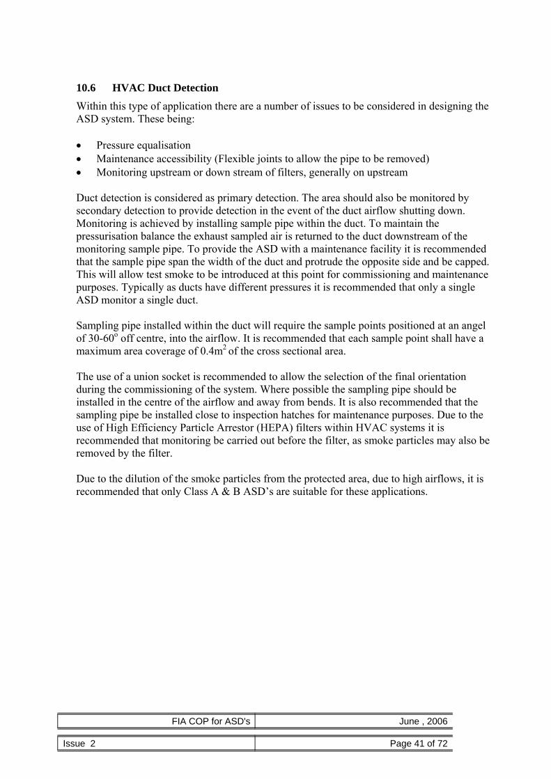
FIA COP for ASD's June , 2006
Issue 2 Page 41 of 72
10.6 HVAC Duct Detection Within this type of application there are a number of issues to be considered in designing the ASD system. These being:
• Pressure equalisation • Maintenance accessibility (Flexible joints to allow the pipe to be removed) • Monitoring upstream or down stream of filters, generally on upstream
Duct detection is considered as primary detection. The area should also be monitored by secondary detection to provide detection in the event of the duct airflow shutting down. Monitoring is achieved by installing sample pipe within the duct. To maintain the pressurisation balance the exhaust sampled air is returned to the duct downstream of the monitoring sample pipe. To provide the ASD with a maintenance facility it is recommended that the sample pipe span the width of the duct and protrude the opposite side and be capped. This will allow test smoke to be introduced at this point for commissioning and maintenance purposes. Typically as ducts have different pressures it is recommended that only a single ASD monitor a single duct. Sampling pipe installed within the duct will require the sample points positioned at an angel of 30-60o off centre, into the airflow. It is recommended that each sample point shall have a maximum area coverage of 0.4m2 of the cross sectional area.
The use of a union socket is recommended to allow the selection of the final orientation during the commissioning of the system. Where possible the sampling pipe should be installed in the centre of the airflow and away from bends. It is also recommended that the sampling pipe be installed close to inspection hatches for maintenance purposes. Due to the use of High Efficiency Particle Arrestor (HEPA) filters within HVAC systems it is recommended that monitoring be carried out before the filter, as smoke particles may also be removed by the filter. Due to the dilution of the smoke particles from the protected area, due to high airflows, it is recommended that only Class A & B ASD’s are suitable for these applications.

FIA COP for ASD's June , 2006
Issue 2 Page 42 of 72
11 Product Standards & Marking The EN 54 series of European Standards covers fire detection and fire alarm products. At present there is no published standard covering ASD. However, a working group of CEN/TC72 is currently drafting EN 54-20 “Aspirating Smoke Detectors”. There is a European Insurance Association (CEA) insurance standard for ASDs. This product standard is available as CEA 4022 (formally GEI 1-077 and previously GEI 1-048). Pending the publication of EN54-20 ASD products should comply with this CEA standard. Product should be clearly marked in accordance with the standard to which they comply. ASD products are covered by the Construction Products Directive (CPD) and will eventually be required to show that they meet the Essential Safety Requirements (ESR) of the Directive and CE marked in order to be placed on the market within the European Union. EN54-20 has been included in a mandate under the CPD and when published will become a harmonized product standard. Products manufactured to this harmonized standard that have successfully met the attestation process given in the standard and verified by a Notified Body will be CE marked to show that they meet the ESRs of the Directive. Note: Until EN 54-20 is published and harmonized, ASD products will not be required to be CE marked to show compliance with the CPD. For further information on the CPD and CE marking see FIA Fact File No.9.

FIA COP for ASD's June , 2006
Issue 2 Page 43 of 72
12 Limitation of False Alarms False alarms may be categorized into “unwanted alarms” caused by fire like phenomena in the protected environment and “equipment false alarms” caused by faults in the detection equipment or system. BS 5839-1: 2002 section 3 defines two further categories; “malicious false alarms” arising from malicious actions and “false alarms with good intent” arising from intentional but misguided operation of a call point. In relation to ASD systems only “unwanted alarms” and “equipment false alarms” are considered.
12.1 Unwanted alarms ASD systems can operate at levels of sensitivity much higher than conventional point type smoke detectors. As a result it is sometimes stated that they are more prone to false alarms than conventional systems. However, in the majority of ASD systems unwanted alarms are uncommon. In fact, there is evidence of number of instances where the alarm has been raised by an ASD system but on inspection of that area no obvious signs of a fire have been identified. A false alarm has been recorded but subsequently a fire has developed. Appropriate training is therefore essential – particularly where pre-alarm or condition warnings form part of the intended response plan.
ASD manufacturers’ have introduced a range of features into ASD systems to minimise the likelihood of such false alarms. Careful consideration should be given to the relevance and value of these features to any particular application and the following notes are intended to provide an overview of some of the techniques employed.
12.1.1 Alarm Thresholds Almost all ASD systems allow for adjustment and refinement of the alarm thresholds (and/or detector sensitivities) to ensure that they are appropriate to the protected environment and level of protection required. In addition, many ASD systems incorporate software that may:
- continually alter the threshold/sensitivity to reduce the likelihood of false alarms by considering the dynamics of the normal background readings; - modify the alarm decision according to the dynamics of the signal leading up to the alarm condition (such as the rate of rise) or the use of multiple sensor inputs; - average the measured signal to smooth out normal transients; - operate for a set period to “learn” an environment and automatically set appropriate thresholds/sensitivity at the end of the learning period.
12.1.2 Fault Logs Many ASD systems incorporate historic logs, which provide accurate data to support the investigation of any unusual or unwanted alarm conditions. Such on-board historic logs vary in size and complexity. Therefore consideration should be given to the amount and quantity of historic data that would be suitable to a particular application. Where there are phenomena present that may lead to “unwanted alarms” a more comprehensive logging facility may be desirable.
12.1.3 Multiple alarm thresholds Multiple alarm thresholds (condition warnings) are available on the majority of ASD systems. Trained personnel are able to respond to condition warnings and take appropriate action. Clearly, where the warning is related to a fire condition, it can be tackled before it escalates. However, where the alarm is identified as being unwanted, for

FIA COP for ASD's June , 2006
Issue 2 Page 44 of 72
example, caused by activity in an area (e.g. soldering or minor building works) then the activity can be curtailed before disruptive evacuation procedures are initiated.
12.1.4 Referencing Referencing is a technique used by several ASD manufacturers’ to reduce false alarms caused by the introduction of pollution or smoke from the external environment. Essentially the smoke obscuration of the incoming air is measured and this signal is used to offset the measurements from active detectors within the protected area. Manufactures instructions should be followed to ensure that reference detectors are correctly configured.
12.1.5 Alarm Delays The majority of ASD systems support alarm delays whereby the alarm threshold must be exceeded for a preset period before the alarm or condition warning is signalled. This is a very effective technique for minimising unwanted alarms caused by short transients.
12.1.6 Day Night Setting Many ASD systems provide alternative sensitivity setting that can be applied according to the occupancy or time of day. This allows for less sensitive detection during the periods when the area is occupied.
12.1.7 Software Algorithms Many ASD systems incorporate technology and/or software algorithms to cancel out the effect of spikes in the signal that may be caused by individual dust particles. Such rejection methods ensure that the dust does not contribute to the measured signal.
12.1.8 Filtering Many ASD systems use physical filters to remove larger dust particles from the air sample before it is analysed. These may be incorporated into the ASD equipment or installed in the pipe-work upstream of the detector. Such filters can reduce the risk of unwanted alarms caused by dust/dirt and can minimise contamination of the detector in particularly harsh environments. In addition to the specific features of individual ASD systems there is much that can be done during the design (section 8) and installation (section 13) of such systems to minimise the risk of unwanted alarms. In some applications there may be potential for reduction of false alarms by the use of coincidence detection (clause 8.8).
12.2 Equipment alarms
False alarms by equipment faults can be minimised by choice of good quality equipment that satisfies the relevant equipment standards that has third party certification, and has been regularly serviced and maintained in accordance with 15 and manufacturer’s recommendations.

FIA COP for ASD's June , 2006
Issue 2 Page 45 of 72
13 Installation Air sampling installations should be given the following considerations and as a minimum consist of the following: -
• Siting of Equipment, including the detector, control equipment, power supplies, repeat or remote displays and any other device associated with the ASD system
• Electrical installation to include power, loop and associated interface wiring • Mechanical installation to include installation of pipe, necessary mounting/fixing
assemblies and any other associated works • Inspection, testing, commissioning including performance tests of the installed
systems Before installing the equipment ensure that the manufacturer’s instructions are observed.
13.1 Siting of Equipment Wherever possible equipment should be installed at a location that is easily accessible and gives consideration for future maintenance & servicing. In particular ensure that sufficient space is provided to all points of access such as covers, connectors and cable entries.
For the detectors the maintenance requirements for any filters and removal of sampling pipes should be considered. Whenever the detector is installed outside the risk, consideration should be given to arranging for an air return of the exhaust air back into the protected area to avoid the effects of any significant pressure difference. Generally differences of less than 50Pa do not require return of the exhaust but this must be confirmed by the ASD manufacturer. Where the detector has indicators or a display that is required to be visible it should be sited accordingly. Local environmental conditions and risks should be taken into account. For example, avoidance of inadvertent mechanical damage, moisture, extreme temperature etc.
13.2 Electrical Installation
Generally ASD electrical cabling should be to National Standards, in the UK it should comply with BS 5839 Part 1:2002 clause 26. A risk assessment should determine whether enhanced or standard cabling is needed;
• From a local power supply to the ASD. • From the ASD to the house fire system/CIE. • To any remote or repeat ASD displays.
13.3 Mechanical Installation
13.3.1 Pipework Installation of the pipe-work in PVC, ABS or any other material recommended by the manufacturer should give consideration to the following external influences:

FIA COP for ASD's June , 2006
Issue 2 Page 46 of 72
• Undue stress • Mechanical Impact • UV radiation • Temperature extremes • Future building operations
All pipes should be clearly labelled to indicate its purpose in a fire protection system.
Installations in red ABS pipe is considered normal but is no way restrictive as some applications require pipe to be installed to match the building aesthetics. Suitable and sufficient fixing supports must be used & designed to each individual application. They should be agreed with all appropriate parties concerned before installation commences. Guidance should be taken from the ASD manufacturer and/or pipe manufacturer. Typical fixings include:
• Open or closed clips for surface mounting • Fast fix clips and tie wraps onto suitable beams, joists or other structural steelwork • Double tie wrap onto false floor stanchion
Installations of pipe work in extreme environments should give special consideration to thermal expansion and contraction when supporting & jointing pipe. Guidance should also be sought from the ASD manufacturer and/or the pipe manufacturer. Metal pipe installations should be earthed in accordance with national standards.
13.3.2 Sampling points Sampling points can either be drilled directly into the main sampling pipe or be positioned several metres from the main sampling tube using extended sampling pipe or capillary tubes.
13.4 Labelling requirements The following parts of an ASD should be clearly labelled;
• Sampling Pipe • Sampling Points • ASD Units • Power Supplies and battery enclosures (if separate)
The labelling should clearly identify the purpose and where appropriate the zone/location of the equipment. Where discreet installations are required labelling will be detrimental to the desired visual effect. In this situation it is essential to supplement the ASD with a plan of the protected area showing sampling points and/or sampling pipe locations.
13.4.1.1 Extended sampling pipe or capillary tube
If a concealed pipe installation is required, capillary air sampling can provide a

FIA COP for ASD's June , 2006
Issue 2 Page 47 of 72
solution. In many cases the main sampling pipe is installed in the ceiling void/building structure and a capillary tube taken from the main pipe to the sampling point. The sampling points are then at the end of this capillary tube.
The sampling point may be flush mounted or protrude into the space to be protected (see figure 4). In some cases it is appropriate to have a concealed sampling point.
Figure 4 Examples of capillary sample point mounting
Note: The flush mounted Capillary is often used for thicker ceilings as they are fixed from the front.
Capillary sampling may be used to position sampling points in specific locations - e.g. in the outlet flow from enclosed equipment or near specific hot spots on a machine, thereby negating the need to run the main sampling pipe through complicated routes Particular attention should be paid to the mechanical integrity and routing of the capillary tubes and fittings to minimise the risk of inadvertent disconnection or damage. The maximum capillary length should be established by the system manufacturer.
13.4.1.2 Sampling points
These may be realised either by drilling custom sizes or drilling common sizes and using reducing ports or sheets. In either case care should be taken to make sure the sampling point has the correct hole-size and that any swarf from the drilling process is removed from the sampling pipe. Ensure that it is clear which party is responsible for drilling the sampling holes! Every sampling point should be clearly labelled.
13.5 Inspection It is necessary to carry out an inspection of the completed installation to check for quality of workmanship, correct use of materials and that the installation fully complies with the correct National Standard that the intended ASD systems have been installed to. During inspection it might be necessary to clean the internal pipe system to remove unwanted swarf debris and dust which could affect the ASD system performance. This may be done by either a positive blowing-out of the pipe network with compressed air or by the use of a vacuum cleaner. Guidance should be sought from the manufacturer.

FIA COP for ASD's June , 2006
Issue 2 Page 48 of 72
14 Commissioning and Handover
14.1 Commissioning Testing Commissioning tests should be carried out depending on the ASD system application and only when the building is in its normal, intended running state. Appropriate commissioning tests should also be performed after modifications and/or additions to the ASD system.
14.2 Commissioning There are several stages during the commissioning process, which should be carried out, recorded and checked as necessary:
• Inspection of Installation – Confirm conformity to design, category of system (see
section 5) including mechanical & electrical installation.
• Power up/Configuration– Required checks and configuration
• Commissioning tests – To include mechanical, functional and performance testing.
• Signalling - To verify the connections between ASD and other connected systems (e.g. CIE, BMS).
• System Handover – Including relevant documentation and recorded drawings.
14.2.1 Inspection of Installation It is necessary to inspect the installation, to confirm that it has been designed and installed correctly for the application and conforms to the design documentation. In particular;
• When using ASD for high and enhanced sensitivity (Class A/B) - ensure that the
installation conforms to the Design specification (e.g. it may be necessary to measure the air velocities in the protected area to ensure that the design spacing is appropriate. (See section 8).
• When using ASD as a primary sampling system, ensure the pipe and sample points
are installed correctly onto the Air Handling Unit (AHU) within the airflow. If monitoring more than one AHU, it is important to ensure different running speeds do not cause an unbalanced airflow in the pipe, which may affect ASD performance.
• When using ASD to replace point type detectors (Class C) – ensure the installation
(particularly sample point spacing) conforms to the relevant standard (e.g. BS 5839-1: 2002) and the ASD sensitivity/alarm thresholds are correctly set to ensure that the sensitivity of individual holes meet the minimum performance requirements for individual points. Note that this may require reference to the approval compliance notes for the particular ASD system and should also take into account any potential automatic adjustments of the sensitivity/threshold settings, which may occur after commissioning.
• When using ASD for other Installations (Cabinet, duct work or other specialist
protection) – confirm that the ASD system is in accordance with the design.

FIA COP for ASD's June , 2006
Issue 2 Page 49 of 72
A thorough inspection of the mechanical and electrical installation should also be carried out to include;
• Pipe network including correct supports. • Clear identification of sampling points. • No obstructions to sampling points/remote capillaries. • All internal & external electrical wiring has been installed correctly. • Power supplies are correctly sized and provide the correct emergency battery
standby period. • Correct hole position and sizes depending upon ASD Application &
Manufacturer.
Before the ASD is powered, it is very important to check that the installer has cleared the pipe of any foreign articles e.g. swarf, dust etc that will impede or stop the ASD performance. (see clause 13.5)
14.2.2 Power up/Configuration It is very important that the ASD manufacturer’s technical documentation is followed during system set-up. If there is any doubt refer back to the manufacturer for clarification. The system should be powered up in accordance with the manufacturer’s recommendations. Prior to carrying out any functional and performance tests the ASD equipment should be configured for:
• Fire signal alarm thresholds and detector sensitivity settings to give required
sampling point sensitivity. • Alarm and Fault delay periods. • Airflow parameters. • Any other defined parameters.
14.2.3 Commissioning Tests Before these tests are carried out ensure that the room or area being protected is in its operational state – both in terms of airflows and cleanliness. For example, any air handling units should be running, all floor and ceiling tiles should be installed and any equipment producing a heat load should be in its normal operational mode. For ASD systems that are designed to confirm to prescribed standards, commissioning tests should include but are not limited to: -
• Maximum smoke transport time from last sampling hole in system. • Fault detection, including blockage & rupture of the pipe. • Tests to confirm that sampling points are functioning.
For ASD systems that are designed to confirm to a performance requirement additional performance tests should be performed.
14.2.3.1 Transport time Measurement
Maximum transport time is measured by introducing a small quantity of smoke or aerosol into the furthest sample hole (or a dedicated test point) and measuring the time between first introducing the smoke and observing a “reaction” at the detector. Depending on the ASD devise used, the “reaction” is usually a first response of a

FIA COP for ASD's June , 2006
Issue 2 Page 50 of 72
bargraph but may also be the first indication of an alarm. However, where an alarm indication is used it does not generally include any alarm delays, which are temporary set to zero for the measurement of transport time.
Where there are multiple branches or pipes it is essential that each branch is tested individually to confirm the full integrity of the pipe-work.
The maximum transport time shall be less than the maximum time specified within the design documentation (Appendix H2) and shall be less than the maximum limits specified in clause 9.3.3,
All measurement should be recorded for later reference during maintenance. Where possible, measured transport time should be compared to the predicted design transport time.
14.2.3.2 Fault Detection
To ensure continuous integrity of the pipe-work it is recommended that each pipe entering the ASD unit is first blocked and then ruptured (i.e. opened) to ensure that low and high flow faults are reported.
It may be required that blockage of sampling holes is identified, (for example due to high probability of malicious tampering) and appropriate tests should confirm this. It is recommended that, where possible, flow readings are recorded during commissioning for later reference during maintenance. Note: A 20% reduction in volumetric flow (EN54-20) is considered an appropriate fault condition. It is generally the case that sampling holes do not block individually but all become contaminated at similar rates. In this case, regular maintenance, including inspection/cleaning of sampling holes and monitoring for changes in pipe flow rate between visits is sufficient to ensure the integrity of the ASD system. Any faults with the power supply should be detected and signalled appropriately. As a minimum it is recommended that first the battery and then the mains supply are disconnected to verify that a PSU fault is reported. All ASD systems monitor for internal faults and many include a fault test feature to simulate an internal failure. Where this feature is provided it should be used to verify that internal faults are reported. Alternatively disconnection of an internal lead may be used to simulate internal failure after consultation with the manufacturer.
14.2.3.3 Functional tests
Commissioning must include sufficient testing to verify that sampling holes are fully functional. The functional tests described in clause15.2.2 provide guidance on how this should be done. However, careful inspection/validation of the sampling holes to confirm that they are correctly drilled and comparison of measured transport times to predicted transport times is often considered sufficient validation – particularly where performance tests are also specified. The actual current drawn from the power supply should be measured and recorded to

FIA COP for ASD's June , 2006
Issue 2 Page 51 of 72
ensure that the designed standby period can be achieved.
14.2.3.4 Performance Tests
Where performance based tests are required (clause 5.3) they should be conducted in accordance with the design requirements. In many cases a smoke performance test from this Code of Practice will be specified.
Results from the test; particularly details of the test positions, should be recorded so that they can be repeated during maintenance when necessary.
14.2.4 Signalling All signalling between the ASD system and house fire alarm system/CIE should be verified in accordance with the design. In particular the signalling and response to each alarm level and fault conditions should be checked and verified. Where an ASD system provides local disablement or isolation it should be verified that this condition is signalled to the house fire alarm/CIE Any “cause and effect” requirements – particularly in relation to the integration with automatic suppression systems should be verified.
14.2.5 System Handover During the commissioning all results shall be recorded. These along with all configuration data shall be submitted as part of the commissioning certificate. All relevant drawings shall be submitted to include the pipe layout, hole sizes, sampling point positions and detector locations, and shall be deemed part of the system handover. All the collated documentation along with a signed certificate should be issued to the customer.

FIA COP for ASD's June , 2006
Issue 2 Page 52 of 72
15 Maintenance As with all fire systems ASD's require regular maintenance, to ensure their continued performance and reduce the potential for false alarms. It should be noted that maintenance may be a legal requirement and while ASD's may be considered low maintenance they are not "no maintenance".
The frequency and method of maintenance should be clearly documented for each installation and determined by a risk assessment that should include consideration of at least the following; • Equipment installed in dirty conditions will need to be checked more thoroughly and at
more frequent intervals than that in clean and dry situations. • The class of the system. • Value or extent of the risk. • Detector technology employed. • Manufacturer’s recommendations. • Practicalities of performing maintenance/testing of sampling points.
15.1 Frequency of maintenance Maintenance should be carried out at least annually. The routine to be adopted in individual premises may vary with the use of the premises.
15.2 Recommendations for routine Inspection and functional testing ASD manufacturer’s instructions for maintenance and functional testing should be followed.
In general the maintenance of an ASD system involves inspection/test of all elements of the system and with an overall functional test to ensure it's continued performance.
15.2.1 Routine Inspection All fault and alarm output functions of the ASD should be tested where practicable and also any interfaces which may form part of the system. It is important to ensure that operation during testing does not result in an unwanted signal being sent from the ASD to another system.
Where ASD systems contain power supplies and battery back-ups these should be checked and tested in accordance with appropriate national standards (e.g. BS 5839-1) Any components fitted to the system with a defined operating life as defined by the manufacturer should be examined and replaced if necessary (e.g. filters, batteries). It should be checked that there have been no unauthorised changes to the system configuration (e.g. Sensitivity). If changes are required or have taken place, then these must be documented. Any systems reliant on additional additives should be topped up in accordance with the manufacturer’s recommendations.
A visual inspection should be made to check whether structural, building or occupancy changes have affected the design requirements for the pipe-work and sampling points.

FIA COP for ASD's June , 2006
Issue 2 Page 53 of 72
A visual inspection should be made of all sampling points, pipe-work, fittings, cables and equipment for secure fixing, appropriate labelling and for absence of damage and freedom from obstructions. All systems must be functionally tested.
15.2.2 Functional Tests The objective of the functional test of a system is to ensure that the ASD and its associated pipe-work are still operational. This is ideally achieved by introducing smoke into each sampling point in turn and verifying a response at the detector. However where access is restricted or other conditions prevent this, other verification techniques should be employed such as:
• Verifying transport time from the furthest hole or a dedicated test point and
comparing with the original and all previously recorded results to identify deviations.
• Confirming that the flow monitoring is capable of detecting loss of a single sampling point or collection of sampling points that are deemed to be acceptable for the risks involved.
• Inspection of flow readings and comparing with original and all previously recorded results to identify deviations that would indicate a loss of detection performance.
• Measurement of the pressure at each sampling point and comparing with original and previously recorded results to identify deviations that would indicate a loss of detection performance.
The technique used is dependent on the particular features of the ASD technology, the risk and the specific application and should be considered at the design stage (see section 8.6). Such techniques may also be supported by visual inspection of sampling points where this is possible but it is essential to verify that adequate detection performance is maintained. Details of the techniques used must be recorded and agreed with all parties.
Notes
1. Simulation smoke aerosol cans may leave residue if used to test ASD systems and / or particle lifetime maybe insufficient. Their acceptability needs to be verified by the ASD manufacturer.
2. The functional test carried out should not involve more than one sampling point at a time. Too large a test source is likely to affect more than one sampling point and invalidate the test results.
3. Differences in times to respond can indicate pipe-work and / or detection problems and / or changes to the pressure differentials between the protected areas. Response time differences should be investigated.
4. If the original commissioning time is not known or the acceptable deviation from it is not understood then all sample holes or groups of sample holes must be tested individually in accordance with the requirements of BS 5839-1: 2002. Where access to individual holes is restricted it may be necessary to clean the system and re-test in accordance with clause 14.2.3
5. Where the ASD is specifically installed to provide early warning, regular repetition of the original commissioning performance smoke tests (clause 14.2.3.4) (e.g. hot wire tests) may be necessary to ensure that the original performance capability has
FIA COP for ASD's June , 2006
Issue 2 Page 54 of 72
not been compromised. 6. Many of these systems are installed in sensitive areas and permission is necessary
even for the smallest amount of smoke / surrogate smoke. Where permission cannot be granted for a smoke test, other methods, such as measuring the suction pressure at each sampling point, may be used to make an assessment of the system performance.
16 User Responsibilities Clause 47 of BS5839-1: 2002 clearly identifies the need for the user of a fire detection and fire alarm system to appoint a person responsible for supervising “all matters pertaining to the fire alarm system”. It is especially important that a responsible person is appointed to supervise an ASD system, whether it is a “stand alone” system or an integral part of the overall building fire detection and fire alarm system. As well as carrying out the general duties laid out in Clause 47 of BS 5839-1: 2002, the responsible person shall be trained in identifying potential environmental influences and situations which might affect the satisfactory performance of an ASD system, and actions which can be taken to overcome those problems. Problems may arise from;
• Changes to the use of the premises; • Changes to the layout of the premises; • Introduction of new processes or changes to existing processes; • Changes to the internal environment, such as installation of new air-conditioning; • Changes to the external environment, such as an increased level of background diesel
fumes or increased levels of exhaust from another factory in close proximity.

FIA COP for ASD's June , 2006
Issue 2 Page 55 of 72
Appendix A – ASD System Performance Tests
Commissioning – ASD System Performance Tests
The table below presents a matrix of performance tests according to the desired response of the system (Class A, Class B or Class C) and the type of application. This table should be used as a guide to select the most appropriate performance test to be carried out during commissioning and maintenance of a specific ASD system. Type Application Response Class A Response Class B Response Class C
Clean room, Telco or computer facility (ceiling <3m)
2m PVC wire
1m PVC wire
7-9g pellet Primary
Other (inc open areas and high ceilings)
1m PVC wire
7-9g pellet 13-18g pellet
Low ceilings (<3m) 2m PVC wire
1m PVC wire
7-9g pellet Poly’ mat Lactose
Normal ceilings (up to 20m)
7-9g pellet
13-18g pellets
2x13-18g pellets poly’ mat Lactose
Secondary
High ceilings (>20m) N/A 2x13-18g pellets Lactose Localised Ideally devise
custom test to reflect risk – otherwise use…
2m PVC wire
1m PVC wire
7-9g pellet poly’ mat Lactose
Vented/cooled 2x12ohm for 80sec 2m PVC wire 1m PVC wire Unvented <3m3 12 ohm for 70sec 2x12ohm for 80sec 2m PVC wire
In-Cabinet
Unvented >3m3 12ohm for 8 sec 12 ohm for 70sec 2x12ohm for 80sec For smoke generated in the Duct
2m PVC wire
1m PVC wire
7-9g pellet Duct
For smoke generated in the room, devise custom test to reflect volume and usage of space protected.
1m PVC wire
7-9g pellet 13-18g pellet
Note – where PVC wire tests are specified, details are given in the appendix E for an alternative test using LSF (Low Smoke and Fume) cable. In addition to these general tests, 2 additional sets of performance tests are defined within this Code of Practice (Appendices C & D) which have been specifically included to support detectors based on the Cloud Chamber technology. These tests reflect the specialist nature of this detection technology in the protection of specific risks. Note. All the tests presented below give off noxious fumes and suitable precautions should be taken to protect operators in accordance with appropriate risk assessments Note. There is a fire hazard with these tests and an appropriate type of fire extinguisher should always be to hand when preparing for and undertaking the tests Note It is the responsibility of the person carrying out the tests that electrical safety is maintained at all times. The Electrical tests described within this document are functional methods and do not attempt to cover the requirements for electrical safety.

FIA COP for ASD's June , 2006
Issue 2 Page 56 of 72
Appendix B - Smoke Pellet performance test Apparatus : Butane gas burner (or equivalent electrical heater) with an output of 5.8KW (Note a 5.8KW burner
burns 10g of butane in 70 seconds) Metal chimney typically 2mm thick formed into a cylinder of 100mm min diameter and 150mm high1 A calibrated stop clock or stop watch, capable of measuring in 1 second intervals Smoke pellet of appropriate weight A 200mm square (approx.) metal platen1
Test Procedure :
The metal platen should be placed upon the burner and the pellet placed centrally on the platen. The chimney is then placed centrally around the pellet. The table below should be used to determine the length of time that the burner is operated for. The burner should be ignited and the timer started once the pellet starts producing smoke. When the determined time (see table below) has elapsed then burner should be extinguished. The pellet will continue to produce smoke when the burner has been extinguished (typically 30-60 seconds) but thermal lift will not occur. Any variations from the test procedure above e.g. omitting the chimney, smaller burner or positioning the smoke pellet by the side of the burner should be documented on the commissioning form.
Test Requirement :
The ASD is required to signal a response within 180 seconds of the burner being switched off. The response shall be a full fire condition unless agreed otherwise e.g. Local alarm, Pre-alarm.
Temperature Differential (°C) Burner Operation Times :
Height (m) <3°C 3 to 6°C 6 to 9°C 9 to 12°C 12 to 15°C
3 -5 3s 6s 9s 12s 17s 5-10 7s 13s 20s 27s 34s 10-15 10s 20s 30s 40s 51s 15-20 13s 27s 40s 54s 67s
. Note 1 Either the base of the chimney or the metal plate should have holes to provide ventilation for the
chimney.. Note 2 No heat input is required for applications with a height of less than3 metres when conducting these
tests. Note 3 Temperature differential is the temperature difference between the level at which the test is
conducted and the level at which the aspirating sampling points are mounted. Note 4 The times in the above table are based upon 5.8KW burner, a smaller burner can be used i.e. 1.2KW
but the times may need to be extended to reach the same end of test criteria.

FIA COP for ASD's June , 2006
Issue 2 Page 57 of 72
Appendix C - Paper Burn performance test Paper Burn tests are used for performance based testing of Specialised ASD systems based on Cloud Chamber technology , this test is used where thermal lift may be expected. Apparatus : Butane gas burner (e.g. 5.8kW)
Steel chimney typically 6mm thick formed into a cylinder of 50mm diameter and 300mm high The Steel chimney should be capped with a removable steel mesh on the top to prevent the embers from being lifted into the air. (the mesh size should approximately 10mm) A calibrated stop clock or stop watch, capable of measuring in 1 second intervals A4 sheet of white paper (80g per m2)
Test Procedure :
The chimney is then placed centrally on the burner so that the flames surround the chimney (See diagram XX) The sheet of A4 paper should be rolled lengthways and placed inside the chimney so that the paper contacts with the sides of the chimney The Steel mesh cap should be fitted The burner should be ignited and the timer started once the paper starts producing smoke. When a further 180 seconds has elapsed then burner should be extinguished. Thermal lift will occur during the whole test.
Test Requirement :
The ASD is required to register a response – equivalent to at least a 15% increase in reading (where 100% is the fire threshold) over the background level sufficient to signal a pre-alarm or warning condition – before the end of test.

FIA COP for ASD's June , 2006
Issue 2 Page 58 of 72
Appendix D - Overheated Enamel Wire performance test Overheated wire tests are used for performance based testing of Specialised ASD systems based on Cloud Chamber technology , this test is used where no thermal lift may be expected. Apparatus : Isolated a.c. variable power supply capable of supplying 100A at 8V
Fire resistant board with insultators for supporting the wire Calibrated voltmeter and Ammeter A calibrated stop clock or stop watch, capable of measuring in 1 second intervals Test wire - 18AWG Enamel coated wire
Test Procedure :
The two ends of the appropriate length of wire (see Appendix A) should be connected to the terminals of the power supply and routed around the insulators on the fire resistance board. The wire should form a single path without any kinks or crossovers. The wire should be suspended and should not touch the fire resistance board (see figure XX) The power supply should be switched on and adjusted within the first 10 seconds to provide 4 V a.c. This is the start of the test. When a further 180 seconds has elapsed then power supply should be turned off, the test is completed 120 seconds later (total test time 300 seconds)
Test Requirement :
The ASD is required to register a response – equivalent to at least a 15% increase in reading (where 100% is the fire threshold) over the background level sufficient to signal a pre-alarm or warning condition – before the end of test.

FIA COP for ASD's June , 2006
Issue 2 Page 59 of 72
Appendix E –Overheated PVC/LSF Wire performance tests E.1 System performance test using electrically overloaded PVC-coated wire (1 m)
This method is suitable for the testing of high sensitivity (Class A) and enhanced sensitivity (Class B) fire detection systems.
To simulate the early stages of a fire, a length of wire is electrically overloaded so that smoke or vapours are driven off.
Warning. This test produces sufficiently high temperatures to generate small quantities of hydrogen chloride. However, test personnel are unlikely to be exposed to concentrations of hydrogen chloride that exceed the OES (Occupational Exposure Standard) of 5ppm in a 15 minute period unless they are directly exposed to the smoke plume. Hence, where it is impractical to arrange for remote switching of the transformer, or where multiple tests are required, or where personnel stand within the immediate vicinity (e.g. 2m) of the smoke source then it is recommended that personnel wear appropriate protective equipment such as an E1 respirator confirming to EN140 and goggles without ventilation conforming to EN166. Apparatus : Wire, either;
1m in length, of 10/0.1 mm strands insulated with PVC to a radial thickness of 0.3 mm, the cross sectional area of the conductor being 0.078 mm2. or; 2m in length of single strand LSF ethernet 24AWG cable (BICC Brandrex)
Transformer, 240 V to 6 V, capable of supplying at least 15 A.
Insulating board, of non-combustible material, of minimum size 600 mm x 600 mm.
Stop clock or stop watch, capable of measuring in 1 second intervals In addition, an arrangement to shield the overheating cable from the cooling effects of high airflows may be necessary.
Test Procedure :
Connect the wire to the 6 V output terminals of the transformer. Ensure that the wire is laid on the insulating board so that there are no kinks or crossovers. Connect 240 V mains electricity supply to the primary terminals of the transformer for a period of 60 seconds.
Note: After this period most of the insulation should be burnt off.
Test Requirement :
The ASD is required to signal a response (equivalent to at least a 15% increase in reading - where 100% is the fire threshold over the background level) sufficient to signal a pre-alarm or warning condition within 120 seconds of the cessation of energization.
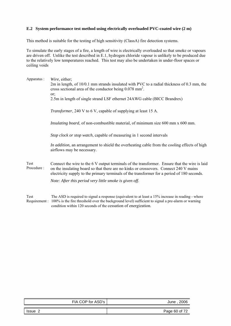
FIA COP for ASD's June , 2006
Issue 2 Page 60 of 72
E.2 System performance test method using electrically overloaded PVC-coated wire (2 m)
This method is suitable for the testing of high sensitivity (ClassA) fire detection systems. To simulate the early stages of a fire, a length of wire is electrically overloaded so that smoke or vapours are driven off. Unlike the test described in E.1, hydrogen chloride vapour is unlikely to be produced due to the relatively low temperatures reached. This test may also be undertaken in under-floor spaces or ceiling voids
Apparatus : Wire, either; 2m in length, of 10/0.1 mm strands insulated with PVC to a radial thickness of 0.3 mm, the cross sectional area of the conductor being 0.078 mm2. or; 2.5m in length of single strand LSF ethernet 24AWG cable (BICC Brandrex)
Transformer, 240 V to 6 V, capable of supplying at least 15 A.
Insulating board, of non-combustible material, of minimum size 600 mm x 600 mm.
Stop clock or stop watch, capable of measuring in 1 second intervals In addition, an arrangement to shield the overheating cable from the cooling effects of high airflows may be necessary.
Test Procedure :
Connect the wire to the 6 V output terminals of the transformer. Ensure that the wire is laid on the insulating board so that there are no kinks or crossovers. Connect 240 V mains electricity supply to the primary terminals of the transformer for a period of 180 seconds.
Note: After this period very little smoke is given off.
Test Requirement :
The ASD is required to signal a response (equivalent to at least a 15% increase in reading - where 100% is the fire threshold over the background level) sufficient to signal a pre-alarm or warning condition within 120 seconds of the cessation of energization.

FIA COP for ASD's June , 2006
Issue 2 Page 61 of 72
E.3 System performance test using electrically overloaded PVC-coated wire (2x1 m)
This method is suitable for the testing of high sensitivity (Class A) and enhanced sensitivity (Class B) fire detection systems.
To simulate the early stages of a fire, a length of wire is electrically overloaded so that smoke or vapours are driven off.
Warning. This test produces sufficiently high temperatures to generate small quantities of hydrogen chloride. However, test personnel are unlikely to be exposed to concentrations of hydrogen chloride that exceed the OES (Occupational Exposure Standard) of 5ppm in a 15 minute period unless they are directly exposed to the smoke plume. Hence, where it is impractical to arrange for remote switching of the transformer, or where multiple tests are required, or where personnel stand within the immediate vicinity (e.g. 2m) of the smoke source then it is recommended that personnel wear appropriate protective equipment such as an E1 respirator confirming to EN140 and goggles without ventilation conforming to EN166. Apparatus : Wire, 2 off 1m in length, of 10/0.1 mm strands insulated with PVC to a radial thickness of
0.3 mm, the cross sectional area of the conductor being 0.078 mm2.
Transformer, 240 V to 6 V, capable of supplying at least 15 A.
Insulating board, of non-combustible material, of minimum size 600 mm x 600 mm.
Stop clock or stop watch, capable of measuring in 1 second intervals In addition, an arrangement to shield the overheating cable from the cooling effects of high airflows may be necessary.
Test Procedure :
Connect the wire in parallel to the 6 V output terminals of the transformer. Ensure that the wire is laid on the insulating board so that there are no kinks or crossovers. Connect 240 V mains electricity supply to the primary terminals of the transformer for a period of 60 seconds.
Note: After this period most of the insulation should be burnt off.
Test Requirement :
The ASD is required to signal a response (equivalent to at least a 15% increase in reading - where 100% is the fire threshold over the background level) sufficient to signal a pre-alarm or warning condition within 120 seconds of the cessation of energization.

FIA COP for ASD's June , 2006
Issue 2 Page 62 of 72
Appendix F – Overheated Resistor performance tests System performance test using electrically overloaded Resistor(s)
The following test methods (F1, F2 and F3) are is suitable for the testing of ASD systems used for the protection of cabinets (containing electronic/electrical equipment such as computer servers or electrical switchgear). They are used in these applications in preference to the hot wire tests because such tests are too bulky and generate large volumes of smoke relative to the confined environment of a cabinet.
Selection of the appropriate test (F1, F2 or F3) for a specific application depends on the performance requirements (response class A, B or C) and the specific arrangement of the cabinet. As a general guide Test F2 produces about 3 times more smoke than F1 and F3 produces about 3 times more smoke than F2.
Warning. These test produces small quantities of noxious fumes which disperse quickly. However, where it is impractical to arrange for remote switching of the transformer, or where multiple tests are required, or where personnel stand within the immediate vicinity (e.g. 2m) of the smoke source then it is recommended that personnel wear appropriate protective equipment such as an E1 respirator confirming to EN140 and goggles without ventilation conforming to EN166. Apparatus : Resistor(s), 12 Ohm, 0.25W carbon film. 1 off for tests F1 & F2, 2 off in parallel for F3.
Transformer, 240 V to 6 V, capable of supplying at least 15 A. Ceramic terminal blocks, 2 off mounted 25mm apart on a non-combustable board (approx 50x50mm) to support and connect the resistors Shielding tube, consisting of a pipe (arrpox 90mm diameter & approx 100mm long) with 8 off 4mm holes aound the base and a cap perforated with 12 off 8mm holes placed over the resistors to shield them from airflows within the cabinet. Stop clock or stop watch, capable of measuring in 1 second intervals
Test Procedure :
Connect the 12 Ohm (0.25W) carbon film resistor(s) to the ceramic terminal blocks. Ensure the resistor(s) is/are not touching anything – excepting the connections to the terminal blocks. Energise the resistor(s) as follows For test F1 - energise for a period of 8 seconds For test F2 - energise for a period of 70 seconds For test F3 - energise for a period of 80 seconds
Test Requirement :
The ASD is required to signal a response (equivalent to at least a 15% increase in reading - where 100% is the fire threshold over the background level) sufficient to signal a pre-alarm or warning condition within 60 seconds of cessation of energization.

FIA COP for ASD's June , 2006
Issue 2 Page 63 of 72
Appendix G - Polyurethane mat performance test This test produces dark smoke and significant thermal lift and is particularly suitable for open areas with ceiling heights greater than 5m.
Apparatus : Polyurethane mat(s), being mat(s) of expanded polyurethane foam (500mm x 500mm x 20mm) complying with the requirements of TF4 in EN54-7:20001 Tray constructed of non-combustible material, lined with aluminium kitchen foil Support, of non-combustible material, to insulate the test fire from the supporting surface calibrated timer
Test Procedure :
Position each of the appropriate number of mats on the kitchen foil in a tray on the non combustible support (see figure X) and ignite a corner of each mat with a match. Renew the kitchen foil after each test. The test is completed 180 seconds after ignition. Note Warning The burning of polyurethane foam generates toxic gases.
Test Requirement :
The ASD is required to register a signal response within 180 seconds of the ignition of the mat The response shall be a full fire condition unless agreed otherwise e.g. Local alarm, Pre alarm
Test mat on its support
1 For information on the availability of suitable foam contact your aspirating system supplier

FIA COP for ASD's June , 2006
Issue 2 Page 64 of 72
Appendix H – Potassium Chlorate / Lactose performance test This test is used for the performance testing of Response Class B and C systems. Fire is simulated by mixing and igniting two volatile powder chemicals to create white smoke with a strong thermal buoyancy. The mixture burns with an intense heat and is not suitable for confined areas. The chemical in storage and transport must be handled with appropriate care according to COSHH guidance.
Apparatus : Potassium Chlorate Lactose powder Steel container Insulating board or wood battens A calibrated timer Long taper Matches/lighter Calibrated measuring spoons –15g ≈ a tablespoon
Test Procedure :
The required amount (see Table below) of lactose and potassium chlorate should be thoroughly mixed together in the steel container. Height (m) Qty Lactose Qty Potassium Chlorate <5m 30g 20g 5m < 10m 45g 30g 10m < 20m 90g 60g 20m < 30m 135g 90g Note: these quantities are suitable for ambient temperatures ranging from 5C to 25C. Temperatures outside these conditions may require additional amounts to accommodate the effects of excessive cooling (colder areas) or thermal stratification (warmer areas). The steel container should be placed on a heat insulating board or wooden battens to prevent heat damage to the floor or supporting surface (high temperatures are generated as part of the test to create thermal lift). The mixture should be ignited with extreme caution at arms length using a long taper or long handled lighter (warning: these chemicals are very volatile when mixed together).
Test Requirement :
The fire detection system is required to signal a response within 180 seconds of the ignition of the mixture. The response shall be a full fire condition unless agreed otherwise e.g. Local alarm, Pre-alarm

FIA COP for ASD's June , 2006
Issue 2 Page 65 of 72
Appendix I – Example Forms
I.1 ASD Planning and Overview Form
Project Name / Reference Client Site Contact Area / Location Reference Drawing Reference
Computer Room Electrical Room In Cabinet Duct Ceiling Void Floor Void Warehouse Atrium Heritage Cold Store Wash down Production
Application
Retail Temperature Humidity Environmental conditions Dirty/dusty
Performance Requirement BS5839 Pt 1 L1 L2 L3 L4 L5 P1 P2 Prescriptive
Standard BS6266 (risk) A B C D E Or Performance based design A:Very early
warning B:Enhanced
Sensitivity C:Normal
sensitivity
Performance test to use Battery backup time required 24 Hours 72 Hours Other Design Information
Room L W H Ceiling Void L W H
Dimensions of protected area
Floor Void L W H Sampling Method Primary Secondary In
cabinet Localised Duct
Number of air return grilles Dimensions of grilles X =
Air Movement / AHU,s / Duct
Dimensions of duct X = Differential pressure Multiple height sampling / vertical spacing (in metres)
Ceiling only
Intermediate levels
Pipe/sampling Requirements Material Colour Diameter Pipe Surface run Concealed
Sample Points In pipe Capillary Drop pipe Pipe supports Maintenance access requirements Equipment Locations ASD units Display(s) Power supply (PSU) Maintenance access requirements Other special requirements Interface requirements to CIE/BMS Alarm level Description 1 2 3 4 Alarm interface Fault(s) Isolate Reset Other

FIA COP for ASD's June , 2006
Issue 2 Page 66 of 72
Actions in event of alarms Alarm level 1 Alarm level 2 Alarm level 3 Alarm level 4 Fault Isolate Sketch Comments………………………………………………………………………………………………….. ……………………………………………………………………………………………………………… ……………………………………………………………………………………………………………… ……………………………………………………………………………………………………………… ……………………………………………………………………………………………………………… Name (in block Letters)……………………………………Position……………………………………… Signature……………………………………………………Date………………………………………… For and behalf of……………………………………………………………………………………………

FIA COP for ASD's June , 2006
Issue 2 Page 67 of 72
I.2 ASD Design Form Project Name / Reference Client Site Contact Area / Location Reference Drawing Reference Planning form reference Performance Requirement
BS5839 Pt 1 L1 L2 L3 L4 L5 P1 P2 Prescriptive Standard BS6266 (risk) A B C D E Or Performance based design A:Very early
warning B:Enhanced
Sensitivity C:Normal
sensitivity
Performance test to use Battery backup time 24 Hours 72 Hours Other Battery/Charger Calculations Battery Charger Expected current consumption Pipe configuration Number of branches Number of sample points In-line features (e.g. filter / water trap / temperature conditioning)
Pipe/Sample point calculation reference Maximum transport time 120 sec 90sec 60 sec Other Predicted transport time(s) ASD unit settings Sensitivity %Obscuration / metre Smoke alarm thresholds 1st 2nd 3rd 4th
Day Night
Time Delays 1st 2nd 3rd 4th Airflow fault thresholds Low High
Alarm Latching Non latching Relay Outputs Fault Latching Non latching
Filtration requirements Cabling Supply from PSU/Charger ASD to display ASD to CIE/BMS ASD network cabling Maintenance Requirements Frequency of maintenance Routine Functional Tests Performance parameters Design notes (to include any variations from the design standard) …………………………………………………………………………………………….…………….. …………………………………………………………………………………………………………… …………………………………………………………………………………………………………… …………………………………………………………………………………………………………… …………………………………………………………………………………………………………… …………………………………………………………………………………………………………

FIA COP for ASD's June , 2006
Issue 2 Page 68 of 72
Sketch I certify that the above system complies to the best of my knowledge with the required design standard, except with variations, if any, as stated above. Name (in block Letters)……………………………………Position………………………………… Signature……………………………………………………Date…………………… For and behalf of………………………………………………………………………

FIA COP for ASD's June , 2006
Issue 2 Page 69 of 72
I.3 ASD Installation Form Project Name / Reference Client Site Contact Area / Location Reference Drawing Reference Design form reference Pipe/Sample point calculation reference Equipment Locations: ASD(s) Display(s) Power supply (PSU)
Material Colour Diameter Surface run Concealed
Pipe
Identified as ASD pipe by labels Pre-printed In pipe Capillary Drop pipe Drilled / sized in accordance with design calculations
Sample Points
Sample point labels installed Cabling:
Cable specification Surface Concealed Conduit
Supply from PSU/Charger
Insulation tested* Earth continuity tested* Cable specification Surface Concealed Conduit
ASD to display
Insulation tested* Earth continuity tested* Cable specification Surface Concealed Conduit
ASD to CIE/BMS
Insulation tested* Earth continuity tested* Cable specification Surface Concealed Conduit
ASD network cabling
Insulation tested* Earth continuity tested* Cable specification Surface Concealed Conduit
Insulation tested* Earth continuity tested* * separate test sheets to be available from responsible electrician “As Fitted” drawings Unless supplied by others, the “as fitted” drawings have been
supplied to the person responsible for commissioning the system. See 36.2m of BS 5839 Pt1.
I certify that the installation complies to the best of my knowledge with the design and conforms to the requirements of BS 7671 and BS 5839-1, except with variations, if any, as stated above. Name (in block Letters)……………………………………Position………………………………… Signature……………………………………………………Date…………………………………….. For and behalf of……………………………………………………………………………………….

FIA COP for ASD's June , 2006
Issue 2 Page 70 of 72
I.4 ASD Commissioning Form Project Name / Reference Client Site Contact
Area / Location Reference Drawing Reference Design form reference Pipe/Sample point calculation reference Installation form reference
Inspection Primary Air handling Duct sampling Secondary Number of sample points
Type of System In Cabinet Number of cabinets
Temperature Humidity
Environmental conditions
Other As fitted installation drawings Are as fitted drawings available ASD Is ASD installed in accordance with the design Display Is display installed in accordance with the design Power supply (PSU) Is PSU installed in accordance with the design Pipe Is pipe installed and labelled in accordance with the design
Variations
Power up/configuration Sensitivity %Obscuration / metre Smoke alarm thresholds 1st 2nd 3rd 4th
Day
Night Time Delays 1st 2nd 3rd 4th Airflow fault thresholds Low High
Alarm Latching Non latching Relay Outputs Fault Latching Non latching
Commissioning tests Transport time(s) Predicted time Actual time Alarm outputs verified Fault outputs verified Reset (if events are latched) Isolate function verified Battery/mains disconnect verified Current consumption verified Hole/pipe blockage fault verified Pipe fracture fault verified Airflow readings (when required)
Pressure readings (when required)
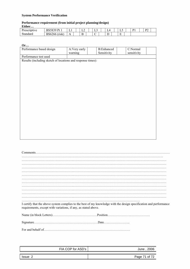
FIA COP for ASD's June , 2006
Issue 2 Page 71 of 72
System Performance Verification Performance requirement (from initial project planning/design) Either…
BS5839 Pt 1 L1 L2 L3 L4 L5 P1 P2 Prescriptive Standard BS6266 (risk) A B C D E Or…
Performance based design A:Very early warning
B:Enhanced Sensitivity
C:Normal sensitivity
Performance test used Results (including sketch of locations and response times): Comments……………………………………………………………………………………………………………………………………………………….…………………………………………………………………………… ………………………………………….…………………………………………………………………………… ………………………………………….…………………………………………………………………………… ………………………………………….…………………………………………………………………………… ………………………………………….…………………………………………………………………………… ………………………………………….…………………………………………………………………………… ………………………………………….…………………………………………………………………………… ………………………………………….…………………………………………………………………………… ………………………………………….…………………………………………………………………………… ………………………………………….…………………………………………………………………………… ………………………………………….…………………………………………………………………………… ………………………………………….…………………………………………………………………………… ………………………………………………………………………………………………… I certify that the above system complies to the best of my knowledge with the design specification and performance requirements, except with variations, if any, as stated above. Name (in block Letters)……………………………………Position………………….……………… Signature……………………………………………………Date…..……………….. For and behalf of………………………………………………………………………

FIA COP for ASD's June , 2006
Issue 2 Page 72 of 72
I.5 ASD Maintenance Form Project Name / Reference Client Site Contact
Area / Location Reference Drawing Reference Design form reference Pipe/Sample point calculation reference Commissioning form reference
Inspection Check design & commissioning. Have there been any design changes since system was last
inspected/commissioned.
Check the configuration Have there been changes to the setting/sensitivity of the detector since the system was inspected/commissioned
Environment and use Have there been any changes in the environment or area usage since the system was inspected/commissioned.
Filters & other serviceable items Checked and replaced as necessary
Maintenance Requirements Frequency of maintenance Routine Functional Test Performance parameters
Tests Transport time(s) Previous times Current times Alarm outputs verified Fault outputs verified Reset (if events are latched) Isolate function verified Battery/mains disconnect verified Current consumption verified Hole/pipe blockage fault verified Pipe fracture fault verified Airflow / Pressure readings (when required)
Performance test results (when required)
Comments……………………………………………………………………………………………………………………………………………………….…………………………………………………………………………… ………………………………………….…………………………………………………………………………… ………………………………………….…………………………………………………………………………… ………………………………………….…………………………………………………………………………… ………………………………………….…………………………………………………………………………… ………………………………………….…………………………………………………………………………… I certify that the above system has been maintained and verified to be fully functional. Name (in block letters)……………………………………Position………………….……………… Signature……………………………………………………Date…..……………….. For and behalf of……………………………………………………………………