coco: composition model and composition model ... composition model and composition model...
TRANSCRIPT
CoCo: Composition Model and Composition ModelImplementation
Naiyana Tansalarak and Kajal T. ClaypoolDepartment of Computer Science
University of Massachusetts - LowellLowell, MA 01854
Technical Report: University of Massachusetts - Lowell, CS-2004-006
Abstract
Component-based software engineering attempts to address the ever increasing demand for new soft-ware applications by enabling a compositional approach to software construction in which applicationsare built from pre-fabricated components, rather than developed from scratch. However, the success ofcomponent-based development has been impeded by interoperability concerns that often come into playwhen composing two or more independently developed components. These concerns encompass fiveincompatibility dimensions: component model, semantic, syntactic, design and platform. In this paperwe now propose a CoCo composition model that elevates compositions to first class citizenship statusand defines the standard for describing the composition of components transparently to any underlyingincompatibilities between the collaborating components; and a CoCo composition model implementa-tion that provides the required support to describe and subsequently execute the composition to producea composed application. In particular, we advocate the use of XML Schemas as a mechanism to supportthe composition model. To support the composition model implementation we provide (1) a taxonomyof primitive composition operators to describe the connection between components; (2) XML documentsas a description language for the compositions; and (3) the development of a set of deployment pluginsthat address any incompatibilities and enable the generation of the composed application (or compositecomponent) in different languages and component models as well as on different platforms.
Keywords: Component model, Component Model Implementation, Composition Model, Composition Model Imple-mentation, Composition Style, Composition Script, Composition Operator, Unifying Component Model
1 Introduction
Component-based software engineering provides a systematic framework for the construction, maintenance,and evolution of software applications and systems. It attempts to address the ever increasing demand fornew software applications by enabling a compositional approach to software construction in which appli-cations are built from pre-fabricated components, rather than developed from scratch. Component-basedsoftware engineering has two fundamental elements, a component model that defines the standard for theinteraction and the composition of components, and a component model implementation (or a componentframework) that provides the dedicated set of executable software elements required to support the executionof the components that conform to the model [16]. A number of component models (with correspondingimplementations) have been defined to date and many have been widely adopted in practice. Examples ofcomponent models are CORBA [28], JavaBeans [22], Enterprise JavaBeans [26], COM [9], and .NET [2].These different component models have stimulated the rapid development of components by different de-velopers, with the hope that eventually most components needed for application building will be availableas off-the-shelf components.
However, the success of component-based development has been impeded by interoperability concernsthat often come into play when composing two or more independently developed components [15, 31, 35].These concerns encompass component model incompatibilities that occur when the to-be composed compo-nents are developed based on the requirements of disparate component models; syntactic incompatibilitiesthat arise when there are signature or interface mismatches between the to-be composed components; se-mantic incompatibilities that typically occur when the behavior expected by one component (the client com-ponent) as specified by the “design by contract” principle is incompatible with the behavior provided by theother (server) component; design incompatibilities that occur when there is an architectural or a design levelmismatch between the to-be composed components; and lastly platform incompatibilities that come intoplay when a component is constructed on one platform but the execution infrastructure supports a differentplatform. Interoperability and hence composability of two or more components may be restricted by one ormore of these incompatibilities, requiring in some cases glue code to enable the collaborative operation oftwo components, while in other cases completely occluding the inter-operation of the given components.
Prior research [25, 23, 7, 36, 37, 17, 14, 27, 6] focusing on interoperability of components has inves-tigated possible solutions to these incompatibilities singularly, rather than as a complete set of concernsthat must be addressed to provide comprehensive support for the composition of components. In this pa-per we now propose a CoCo composition model that elevates compositions to first class citizenship statusand defines the standard for describing the composition of components transparently to any underlying in-compatibilities between the collaborating components; and a CoCo composition model implementation thatprovides the required support to describe and subsequently execute the composition to produce a composedapplication. A component model is incidental to the composition model much as the composition of compo-nents is to the component models, and is described as part of the composition model itself.
Our work targets six key design goals for the CoCo composition model: (1) Architecture- It must allowthe explicit description of the application’s (and the component’s) architecture, such that tools can exploitthis description to reason about throughput, consistency and component compatibility; (2) Extensibility- Itmust be possible to define new subsets of the composition model for a new composition style such thatthey are indistinguishable from the existing standard; (3) Flexibility- It must be possible for developers toconstruct new compositions and edit existing compositions such that they conform to either the complete
2

composition model or a core subset of it; (4) Validation and Verification- It must be possible to validate acomposition against a core subset of the composition model of the specified composition style. Furthermore,it must be possible to verify the structure and the behavior of the composition based on the informationcaptured in the composition; (5) Executable- It must be possible to interpret or generate code from thecomposition configuration. The code generation, however, should not be tied to a single programminglanguage, component model or platform; and (6) Openness- The composition model must be programminglanguage independent and support composition of components from different component models.
In this paper, we present a novel approach to support the CoCo composition model and the CoCo com-position model implementation while simulataneously providing a tight coupling between the model and itsimplementation. In particular, we advocate the use of XML Schemas 1 [32] as a mechanism to not onlydescribe but to also support the design goals of the CoCo composition model. In this paper, we define aset of description models that together describe the composition model, while individually they provide thedescriptions of different composition styles and architectures at a high level, and the format for the actualcomposition at the low level. To support the CoCo composition model implementation we provide (1) ataxonomy of primitive composition operators to describe the connection between components. We hypoth-esize that all complex compositions, where the complex compositions capture the combination of eitherconnection-oriented or aggregation-based compositions or both, can be broken down into a set of primitivecomposition operators. Hence, we define the set of operators to be both minimal in terms of their semantics,and complete; (2) XML documents as a description language for the compositions; and (3) the developmentof a set of deployment plugins that address any incompatibilities and enable the generation of the composedapplication (or composite component) in different languages and component models as well as on differ-ent platforms. We exploit the inherent tight coupling between an XML Schema and an XML document toprovide the same coupling between the composition model (expressed as an XML Schema) and the com-position model implementation enabling us to validate and check the conformance of a composition againstthe composition model (or a core subset of it).
Our work is influenced by both architectural description languages (ADLs) [14, 6, 27] and composi-tion languages (CLs) [4, 33, 8], and we share their goal of overcoming the drawbacks of Object-Orientedlangauges, namely the lack of (i) architectural specification; (ii) support for describing interactions and con-straints; (iii) sequence and dependency of interactions; and (iv) direct support for describing non-functionalrequirements. Our goal however is to not only provide the language for describing the compositions a laADLs and CLs, but to also provide a uniform standard for transparent any incompatibilities.
Roadmap: The rest of paper is organized as follows. We give a brief overview of the fundamentalconcepts that must be supported in a CoCo composition model in Section 2. Section 3 we describe theunifying component model on the basis of which we define our CoCo composition model. In Section 4we describe the description models that together formulate the CoCo composition model. In Section 5 wepresent the set of primitive composition operators that are a core aspect of the CoCo composition modelimplementation. In Section 6 we illustrate the actual description of compositions via the SpeedLogo ap-plication. To complete the CoCo composition model implementation we show in Section 7 the generationof deployable applications based on the described compositions. Section 8 presents related work and weconclude in Section 9.
1We have used in this paper the XML DTD as it provides the concise format. In addition, we provides the XML schemas forour work in www.cs.uml.edu/dsl/XCompose [30].
3

2 CoCo Concepts
In this section we define the fundamental concepts of the CoCo composition model. Our work on definingthe standard for describing compositions is heavily influenced by the concepts that exist in both architecturaldescription languages (ADLs) [14, 6, 27] and composition languages (CLs) [4, 33, 8].
� Component. Component represents the primary computational element of a system wherein eachcomponent must conform to a specified component model such as JavaBean [22], Enterprise Jav-aBeans [26],COM [9] and CORBA [28]. A component is typically classified as either primitive or composite. Aprimitive component is a stand-alone component, that is it does not rely on any other component forits functionality, and is typically constructed in a specific component model, while a composite com-ponent is ususally composed from a set of pre-existing components. Both primitive and compositecomponents consist of (i) a set of properties - to represent the semantic information of a component;(ii) a set of events - to enable a component to interact with other components; and (iii) a set of meth-ods - to enable other components to interact with the component itself. Additionally, a compositecomponent may be described based on the set of underlying components and their compositions.
� Connector. Connector represents the interaction, mediating the communication and coordination ac-tivities, between components. Connectors typically support two types of component compositions:connection-oriented and aggregation-based compositions. A connection-oriented composition [8]describes how components are “plugged” together using event or pipe and filter mechanisms, whilean aggregation-based composition [8] describes the aggregation of components into a higher-levelcomponent using a container mechanism.
� Order. An order, related to a connector and typically applicable to connection-oriented compositions,explicitly specifies the sequence of component interactions. For example, the firing of an event re-quires interaction(s) from one or more components wherein the interactions are accomplished basedon a specified sequential or selective order.
� Constraints. Constraints represent restrictions on how components are composed. These constraintsare typically classified as a set of invariants and contracts. The invariant defines the condition thatmust hold throughout the composition. The contract [21] on the other hand is a set of pre- and post-conditions where the pre-condition defines the conditions under which a composition is legitimate,while the post-condition defines conditions that must be ensured by a composition, that is in theresultant component or application, on return.
� Interface. An interface defines the way a composite component (or application) that is composedfrom a set of pre-existing components may interact with other components (or applications). Aninterface thus specifies a set of properties, events and methods. For example, the composite componentSliderFieldPanel, composed from three primitive componentsjavax.swing.JSlider, javax.swing.JTextField, and javax.swing.JPanel, hasproperties maximumValue, minimumValue, currentValue and fieldWidth; and an event PropertyChangedefined as part of its interface.
4

� Style. A style defines a vocabulary of design element types and rules for composing components,thereby providing a framework of systems. For example, in the GUI composition style [3], the eventand container mechanism are used to achieve the connection-oriented and aggregation-based com-positions, respectively. The design element (component) types thus include the event component - acomponent that emits a set of events; the listener component - a component that listens to a set ofevents; the container component - a component that provides the containment for the containee com-ponents; and the containee component - a component that is aggregated into a container component.Clearly, a component can fall into one or more component types depending on how it is composedin the system. Furthermore, the event and container mechanisms define the composition rules thatspecify the relationship between an event component and a set of listener components; as well as acontainer component and a set of containee components, respectively.
� Topology. A topology represents the overall configuration or architecture of a system that is definedindependent of the components and connectors that make up the system. This topology may be hier-archical, in which case the components and connectors represent a sub-system that has an “internal”configuration (architecture). For example, a Client-Server system consists of two primary compo-nents, Client and Sever components, and the Server component is in turn composed fromConnectorManager,SecurityManager, and Database components.
3 XCM: The Unifying Component Model
A software component adheres to a component model that defines (i) how to construct an individual com-ponent; (ii) the specific interaction and composition standard; (iii) the permitted mechanisms for creatingassembled or integrated connections; and finally (iv) the customization mechanisms describing how com-ponents can be extended without modification [16]. In addition each software component, defined basedon a component model, typically consists of a set of properties, methods and events. Appropriately, muchof the research thus far has focused on developing frameworks for the specification and implementation ofcomponents, resulting in a rich and diverse set of component models such as JavaBeans [22], EnterpriseJavaBean [26], CORBA [28] and COM [9].
However, from a composition perspective, this diverse set of component models represents an interop-erability problem that in many cases limits the composition of components to components developed as perthe requirements of one component model. Given the universal acceptance of XML [1] and its suitabilityfor modeling all aspects of different component models, we now take a descriptive approach and presentan XML-based unifying component model XCM. XCM alleviates the problems that arise from componentmodel incompatibilities allowing composition of heterogeneous components, and provides (i) the descrip-tion of the common subset of properties, method and events defined for the different component models suchas COM, JavaBeans, .NET.; (ii) the introspection infrastructure needed to enable the mapping of compo-nents and their compositions to the specified programming language during deployment; (iii) the support forthe description of architectural layouts for composite components; and (iv) a standard for the construction ofa composite component from components that conform to a heterogeneous set of component models, suchthat it (the composite component) can be reused in larger systems and composed with other components.
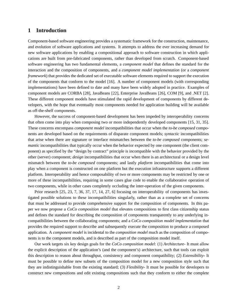
We use XML DTD, as shown in Figure 1, to provide a descriptive representation of XCM. XCM isdescribed via five essential elements: name, properties, events, methods and an optional architecture defined
5
as follows.
� name - name of either the primitive or the composite component;
� properties - set of one or more properties property, where a property is specified via (i) pName - theproperty name; (ii) pType - the property type; (iii)writeMethod - the method name that sets the new property value; and (iv) readMethod - the methodname that gets the property value;
� events - set of one ore more event(s) event, where each event is specified via (i) eName - the eventname; (ii) addListenerMethod - the method name that registers a set of one or more listener com-ponents based on the event; (iii) removeListenerMethod - the method name that removes the listenercomponents for the event; (iv) listenerType - the type of listener components that are allowed to reg-ister for the event; and (v) listenerMethods - set of one or more listener method(s) that the listenercomponents registering for the event must implement. Each listenerMethod is sepcified via (i) mName- the method name; (ii) returnType - the type of value returned from the method; (iii) paraNumber -the number of parameters required for the method; and (iv) paraType - an ordered list of the parametertypes required for the method;
� methods - set of one or more method(s) method, where each method is specified via: (i) mName - themethod name; (ii) returnType - the type of value returned from the method; (iii) paraNumber - thenumber of parameters required for the method; and (iv) paraType - an ordered list of the parametertypes required for the method; and
� architecture - the architectural layout of the underlying components that make up the composite com-ponent based on a specified composition style such as GUI composition style. architecture must thusconform to the composition model defined in Section 4.
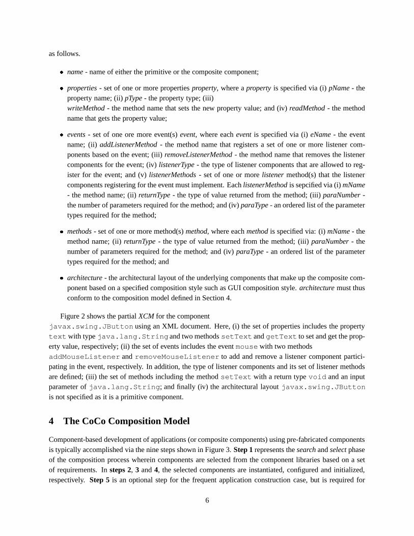
Figure 2 shows the partial XCM for the componentjavax.swing.JButton using an XML document. Here, (i) the set of properties includes the propertytextwith type java.lang.String and two methods setText and getText to set and get the prop-erty value, respectively; (ii) the set of events includes the event mouse with two methodsaddMouseListener and removeMouseListener to add and remove a listener component partici-pating in the event, respectively. In addition, the type of listener components and its set of listener methodsare defined; (iii) the set of methods including the method setText with a return type void and an inputparameter of java.lang.String; and finally (iv) the architectural layout javax.swing.JButtonis not specified as it is a primitive component.
4 The CoCo Composition Model
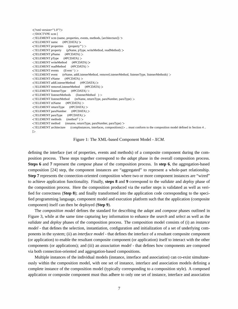
Component-based development of applications (or composite components) using pre-fabricated componentsis typically accomplished via the nine steps shown in Figure 3. Step 1 represents the search and select phaseof the composition process wherein components are selected from the component libraries based on a setof requirements. In steps 2, 3 and 4, the selected components are instantiated, configured and initialized,respectively. Step 5 is an optional step for the frequent application construction case, but is required for
6
�?xml version=”1.0”? �
�!DOCTYPE xcm [
�!ELEMENT xcm (name, properties, events, methods, [architecture]) �
�!ELEMENT name (#PCDATA) �
�!ELEMENT properties (property
�) �
�!ELEMENT property (pName, pType, writeMethod, readMethod) �
�!ELEMENT pName (#PCDATA) �
�!ELEMENT pType (#PCDATA) �
�!ELEMENT writeMethod (#PCDATA) �
�!ELEMENT readMethod (#PCDATA) �
�!ELEMENT events (Event
�) �
�!ELEMENT event (eName, addListenerMethod, removeListenerMethod, listenerType, listenerMethods) �
�!ELEMENT eName (#PCDATA) �
�!ELEMENT addListenerMethod (#PCDATA) �
�!ELEMENT removeListenerMethod (#PCDATA) �
�!ELEMENT listenerType (#PCDATA) �
�!ELEMENT listenerMethods (listenerMethod
�) �
�!ELEMENT listenerMethod (mName, returnType, paraNumber, paraType) �
�!ELEMENT mName (#PCDATA) �
�!ELEMENT returnType (#PCDATA) �
�!ELEMENT paraNumber (#PCDATA) �
�!ELEMENT paraType (#PCDATA) �
�!ELEMENT methods (method
�) �
�!ELEMENT method (mname, returnType, paraNumber, paraType) �
�!ELEMENT architecture (compInstances, interfaces, compositions) � .. must conform to the composition model defined in Section 4 ..
] �
Figure 1: The XML-based Component Model - XCM.
defining the interface (set of properties, events and methods) of a composite component during the com-position process. These steps together correspond to the adapt phase in the overall composition process.Steps 6 and 7 represent the compose phase of the composition process. In step 6, the aggregation-basedcomposition [24] step, the component instances are “aggregated” to represent a whole-part relationship.Step 7 represents the connection-oriented composition where two or more component instances are “wired”to achieve application functionality. Finally, steps 8 and 9 correspond to the validate and deploy phase ofthe composition process. Here the composition produced via the earlier steps is validated as well as veri-fied for correctness (Step 8); and finally transformed into the application code corresponding to the speci-fied programming language, component model and execution platform such that the application (compositecomponent) itself can then be deployed (Step 9).
The composition model defines the standard for describing the adapt and compose phases outlined inFigure 3, while at the same time capturing key information to enhance the search and select as well as thevalidate and deploy phases of the composition process. The composition model consists of (i) an instancemodel - that defines the selection, instantiation, configuration and initialization of a set of underlying com-ponents in the system; (ii) an interface model - that defines the interface of a resultant composite component(or application) to enable the resultant composite component (or application) itself to interact with the othercomponents (or applications); and (iii) an association model - that defines how components are composedvia both connection-oriented and aggregation-based compositions.
Multiple instances of the individual models (instance, interface and association) can co-exist simultane-ously within the composition model, with one set of instance, interface and association models defining acomplete instance of the composition model (typically corresponding to a composition style). A composedapplication or composite component must thus adhere to only one set of instance, interface and association
7

01.�
?xml version=”1.0”? �02.
�xcm �
03.�
name: � javax.swing.JButton �/name �
04.�
properties �05.
�property �
06.�
pName � text �/pName �
07.�
pType � java.lang.String �/pType �
08.�
writeMethod � setText �/writeMethod �
09.�
readMethod � getText �/readMethod �
10.�
/property � ..........11.
�/properties �
12.�
events �13.
�event �
14.�
eName � mouse �/eName �
15.�
addListenerMethod � addMouseListener �/addListenerMethod �
16.�
removeListenerMethod � removeMouseListener �/removeListenerMethod �
17.�
listenerType � java.awt.event.MouseListener �/listenerType �
18.�
listenerMethods �19.
�listenerMethod �
20.�
mname � mousePressed �/mname �
21.�
returnType � void �/returnType �
22.�
paraNumber � 1 �/paraNumber �
23.�
paraType � java.awt.event.MouseEvent �/paraType �
24.�
/listenerMethod � ..........25.
�/listenerMethods �
26.�
/event � ..........27.
�/events �
28.�
methods �29.
�method �
30.�
mName � setText �/mName �
31.�
returnType � void �/returnType �
32.�
paraNumber � 1 �/paraNumber �
33.�
paraType � java.lang.String �/paraType �
34.�
/method � ..........35.
�/methods �
36.�
/xcm �
Figure 2: The Partial Script of the Component javax.swing.JButton Corresponding to The XCMgiven in Figure 1.
8

Step 1:
Step 2:
Step 3:
Step 4:
Step 5:
Step 6:
Step 7:
Step 8:
Step 9:
A d
a p
t C
o m
p o
s e
Instantiation
Configuration
Initialization
Interface Specification
Aggregation-based Composition
Connection-oriented Composition
Validation and Verification
Component-based Application / Composite Component
Component Library
Components
Component Library
S e
a r c
h &
S e
l e c t
Components
V a
l i d
a t e
& D
e p
l o y
Figure 3: The Composition Process - Enabling Plug-n-Play Development of Applications and Composite Components.
models, a la composition style. Each instance of the model is described as an XML Schema, includingthe composition model instance that combines a set of XML Schemas corresponding to a specific set ofinstance, interface and association model instances.
In this section, we now present the instance, interface and association models based on sample instancescorresponding to the GUI composition style. In a GUI composition style aggregation-based and connection-oriented compositions are accomplished using the event and container mechanisms, respectively. An eventcomponent fires an event requiring a set of listener components listening to the event to trigger their re-spective method invocations; and a set of containee components are aggregated into a container componentto govern the creation of a high-level component as well as the display of underlying components. Theinstances of the instance, interface and association models corresponding to other composition styles canbe described in a similar manner. Additionally, in this section, we present the complete instance of thecomposition model corresponding to the GUI composition style, namely the GUI composition model.
4.1 The Instance Model
Composition of two components typically initiates with the selection of a pre-existing component from thecomponent libraries based on a set of requirements. Once selected, the component is then instantiated, andsubsequently configured via its defined set of properties. Finally the component is initialized to capture itsinitial behavior in the composed system. The instance model describes the standard for the specification
9
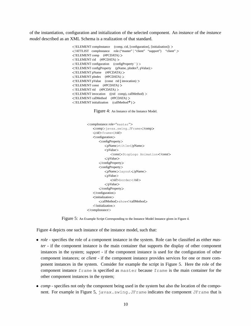
of the instantiation, configuration and initialization of the selected component. An instance of the instancemodel described as an XML Schema is a realization of that standard.
�!ELEMENT compInstance (comp, cid, [configuration], [initialzation]) �
�!ATTLIST compInstance role (“master” � “client” � “support”) “client” �
�!ELEMENT comp (#PCDATA) �
�!ELEMENT cid (#PCDATA) �
�!ELEMENT configuration (configProperty
�) �
�!ELEMENT configProperty (pName, pIndex � , pValue) �
�!ELEMENT pName (#PCDATA) �
�!ELEMENT pIndex (#PCDATA) �
�!ELEMENT pValue (const � rid � invocation) �
�!ELEMENT const (#PCDATA) �
�!ELEMENT rid (#PCDATA) �
�!ELEMENT invocation ((rid � comp), callMethod) �
�!ELEMENT callMethod (#PCDATA) �
�!ELEMENT initialization (callMethod
�) �
Figure 4: An Instance of the Instance Model.
�compInstance role=”master” �
�comp � javax.swing.JFrame �
/comp ��
cid � frame �/cid �
�configuration �
�configProperty �
�pName � title �
/pName ��
pValue ��
const � StopLogo Animation�
/const ��
/pValue ��
/configProperty ��
configProperty ��
pName � layout �/pName �
�pValue �
�rid � border �
/rid ��
/pValue ��
/configProperty ��
/configuration ��
initialization ��
callMethod � show �/callMethod �
�/initialization �
�/compInstance �
Figure 5: An Example Script Corresponding to the Instance Model Instance given in Figure 4.
Figure 4 depicts one such instance of the instance model, such that:
� role - specifies the role of a component instance in the system. Role can be classified as either mas-ter - if the component instance is the main container that supports the display of other componentinstances in the system; support - if the component instance is used for the configuration of othercomponent instances; or client - if the component instance provides services for one or more com-ponent instances in the system. Consider for example the script in Figure 5. Here the role of thecomponent instance frame is specified as master because frame is the main container for theother component instances in the system;
� comp - specifies not only the component being used in the system but also the location of the compo-nent. For example in Figure 5, javax.swing.JFrame indicates the component JFrame that is
10

located in the package javax.swing;
� cid - defines a handler for the instantiated component comp. For example in Figure 5, frame is thehandler that represents the component instance instantiated from the selected componentjavax.swing.JFrame;
� configuration - configures a specified component instance. The configuration of a component in-stance is typically achieved via the initialization of its set of properties configProperty where eachconfigProperty describes the configuration of each property via its
– pName - that specifies the property name of the component instance;
– pIndex - that defines the index of a property if it is indexed property; and
– pValue - that defines the value to be used for the configuration of the property. This value can beeither (a) atomic - a constant string, number, boolean or character. This is given as const in Fig-ure 4; (b) a referrence to another component instance (rid); or (c) a method invocation of either(i) another component instance defined in the system, and specified via rid - a referrence to thecomponent instance, and callMethod - a method of the component instance rid; or alternatively(ii) the component library specified via comp - a component from the component library, andcallMethod - a static method of component comp.
For example, Figure 5 illustrates the configuration of the component instance frame via two ofits properties title and layout. Here the property title has a pValue of a constant stringStopLogo Animation, while layout’s pValue is a reference to the component instance border;and
� initialization - initializes a component instance defining its behavior when it is first deployed as part ofthe system. This initialization is typically achieved by invoking a method of the component instance.initialization is thus described as a set of method invocations callMethod - that invoke a method ofthe component instance. For example in Figure 5, the component instance frame is initialized by theinvocation of its method show.
4.2 The Interface Model
An interface defines the shared boundary across which information is passed, enabling two or more com-ponents to pass information from one to the other component. The interface model is the standardization ofthe specification of this interface for a composite component or application constructed from pre-existingcomponents. Given that the interface in most component models [22, 9] is defined by a set of properties,events and methods, we now present an example instance of the interface model that provides a standarddescription of the interface.
Properties. Figure 6 depicts an example instance of the interface model depicting the description of aproperty. In this case, a newly defined property is bound to an existing property of an underlying component(one-to-one). In addition, its type (readWrite or readOnly) as well as style (simple or indexed orbound or constrained) is specified to provide support for its implementation using any programminglanguage. In particular,
11

� pName - specifies the property name;
� pBinding - specifies the property of an underlying component that is bound to pName. pBinding isspecified via (i) rid - a reference to an underlying component via its component instance defined inthe instance model; and (ii) rProperty - the property name of the component instance rid;
� type - specifies the property type, readWrite or readOnly; and
� style - specifies the property style, simple or indexed or bound or constrained.
Figure 7 depicts a script that conforms to the interface model in Figure 6. Here a new property labelis defined and bound to the existing property label of the component instance button. The type of theproperty is set as readWrite and the style as simple.
�!ELEMENT property (pName, pBinding) �
�!ATTLIST property type (“readWrite” � “readOnly”) ”readWrite” �
�!ATTLIST property style (“simple” � “indexed” � “bound” � “constrained”) “simple” �
�!ELEMENT pName (#PCDATA) �
�!ELEMENT pBinding (rid, rproperty) �
�!ELEMENT rid (#PCDATA) �
�!ELEMENT rProperty (#PCDATA) �
Figure 6: An Instance of the Interface Model for a Property.
�property type=”readWrite” style=”simple” �
�pName � label �
/pName ��
pBinding ��
rid � button �/rid �
�rProperty � label �
/rProperty ��
/pBinding ��
/property �
Figure 7: An Example Illustrating the Specification of a Property in a Script.
Events. Figure 8 depicts an example instance of the interface model depicting the description of anevent. In this case, a new event is defined on a set of events available in the component libraries. Inaddition, the type of the event (multiCast or uniCast) is specified to provide support for its imple-mentation using any programming language. In Figure 8 eName specifies the event name along with itslocation (package), and type specifies the event type whose domain range is multiCast or uniCast.Figure 9 illustrates the declaration of an event in a script based on the interface instance in Figure 8. HerePropertyChangeEvent is an event whose type is multiCast.
�!ELEMENT event (ename, eBinding) �
�!ATTLIST event type (“multiCast” � “uniCast”) “multiCast” �
�!ELEMENT eName (#PCDATA) �
Figure 8: An Instance of the Interface Model for an Event.
Methods. Figure 10 depicts an example instance of the interface model depicting the description ofa method. In this case, a method is defined via the composition of one or more existing methods fromunderlying components (one-to-many). The composition of the methods is defined based on the compositionoperators supported by the composition model implementation, a la the composition model infrastructure.In particular,
12

�event type=”multiCast” �
�eName � java.beans.PropertyChangeEvent �
/eName ��
/event �
Figure 9: An Example Illustrating the Specification of an Event in a Script.
� mName - specifies the method name; and
� mBinding - specifies the binding of the method mName to a set of one or more methods from existingcomponent instances mbCompInstance. The specific composition of two or more methods is stated bythe composition operator op (Section 5.2). Each mbCompInstance is described by a rid - referrenceto an existing component instance defined in the instance model, and a rMethod - the method name ofthe component instance rid to which mName is bound.
Furthermore, method compositions can optionally be nested when a set of methods from componentinstances return outputs that can be considered as inputs for a method of the other component instance.This is indicated by sMethod which is defined similarly to mBinding.
�!ELEMENT method (mName, mBinding) �
�!ELEMENT mBinding (mbCompInstance [op, mbCompInstance] � � sMethod [op, mbCompInstance]
�) �
�!ELEMENT mName (#PCDATA) �
�!ELEMENT mbCompInstance (rid, rMethod) �
�!ELEMENT sMethod (mbCompInstance [op, mbCompInstance]
�) �
�!ELEMENT rid (#PCDATA) �
�!ELEMENT rMethod (#PCDATA) �
�!ATTLIST op type (“
�” � “ � ” � “ � ” � “ � ” � “ � ”) “ � ” �
Figure 10: An Instance of the Interface Model for a Method.
Figure 11 illustrates an example of a script depicting the description of a method paint that is boundto the method paint of the component instance list.
�method �
�name � paint �
/name ��
mBinding ��
mbCompInstance ��
rid � list �/rid �
�rMethod � paint �
/rMethod ��
/mbCompInstance ��
/mBinding ��
/method �
Figure 11: An Example Illustrating the Specification of a Method in a Script.
Figure 12 combines the instances of the interface model given in Figures 6, 8 and 10 into one completeinstance of the interface model encompassing the specification of properties, events and methods.
4.3 The Association Model
Composition defines the exact connection between two or more components. The association model is thusthe standardization of the specification of this connection between components. Typically (based on lit-erature), a composition is classified as either a connection-oriented composition or an aggregation-based
13

�!ELEMENT interface ([properties], [events], methods � ) �
�!ELEMENT properties (property
�) �
�!ELEMENT property (pName, pBinding) �
�!ATTLIST property type (“readWrite” � “readOnly”) ”readWrite” �
�!ATTLIST property style (“simple” � “indexed” � “bound” � “constrained”) “simple” �
�!ELEMENT pName (#PCDATA) �
�!ELEMENT pBinding (rid, rProperty) �
�!ELEMENT rid (#PCDATA) �
�!ELEMENT rProperty (#PCDATA) �
�!ELEMENT events (event
�) �
�!ELEMENT event (eName, eBinding) �
�!ATTLIST event type (“multiCast” � “uniCast”) “MultiCast” �
�!ELEMENT eName (#PCDATA) �
�!ELEMENT methods (method
�) �
�!ELEMENT method (mName, mBinding) �
�!ELEMENT mName (#PCDATA) �
�!ELEMENT mBinding (mbCompInstance [op, mbCompInstance] � � sMethod [op, mbCompInstance]
�) �
�!ELEMENT mbCompInstance (rid, rMethod) �
�!ELEMENT sMethod (mbCompInstance [op, mbCompInstance]
�) �
�!ELEMENT rid (#PCDATA) �
�!ELEMENT rMethod (#PCDATA) �
�!ATTLIST op type (“
�” � “ � ” � “ � ” � “ � ” � “ � ”) “ � ” �
Figure 12: An Instance of the Interface Model Providing the Specification of Properties, Events and Methods.
composition [8]. We now present examples of the association model instances that standardize the descrip-tion of connection-oriented and the aggregation-based compositions.
Connection-Oriented Composition. Figure 13 depicts a connection-oriented instance of the associa-tion model that establishes a connection, triggered by specified events, between components. Componentsin this association model instance can be classified as either event components – that fire events, or listenercomponents – that listen for events and subsequently trigger the specified methods. Specifically, the asso-ciation model instance in Figure 13 describes the relationship between event and listener components suchthat one or more listener components can trigger their methods on occurrence of events fired from one ormore event components. The connection between the event and listener components is established based onthe event composition operators that are provided by the composition model implementation. In Section 5.3we define a set of event composition operators for our association model implementation. Furthermore,the connection between components may be valid only under specified conditions. These conditions arerepresented as constraints on the composition. In particular,
� constraint - specifies restrictions on how event and listener components are connected. Constraints ingeneral are classified as either invariants or contracts. The invariant (inv) defines the condition thatmust always hold during the composition. The contract, described using a set of pre- (pre) and post-conditions (post) defines the conditions under which a composition is legitimate, and the conditionsthat must be ensured by a composition on return respectively. These constraints are expressed in FirstOrder Predicate Logic (FOPL);
� eCompInstances - defines the set of event component instances together with the events to be fired.Each event component instance, eCompInstance, is specified via (i) rid - a reference to the eventcomponent instance defined in the instance model; (ii) event - the event defined in event componentinstance rid; and (iii) eAction - the action defined in the selected event event; and
14

� lCompositions - defines the methods that are triggered by the eAction of the eCompInstance. Thesemethods may be a composition of two or more methods defined in listener component instanceslCompInstance. The composition between the two methods is explicitly specified by the op (Sec-tion 5.2 defines the set of composition operators.). Each lCompInstance is described by its rid - areferrence to a listener component instance defined in the instance model, and a callMethod - themethod name of rid that needs to be invoked.
Furthermore, method compositions can optionally be nested when a set of methods from listenercomponent instances return outputs that can be considered as inputs for a method of the other lis-tener component instance. This is indicated by subLComposition which is defined similarly tolCompositions.
�!ELEMENT eComposition (constraint, eCompInstances, lCompositions) �
�!ELEMENT constraint (inv, pre, post) �
�!ELEMENT inv (#PCDATA) �
�!ELEMENT pre (#PCDATA) �
�!ELEMENT post (#PCDATA) �
�!ELEMENT eCompInstnaces (eCompInstance
�) �
�!ELEMENT eCompInstance (rid, event, eAction) �
�!ELEMENT rid (#PCDATA) �
�!ELEMENT event (#PCDATA) �
�!ELEMENT eAction (#PCDATA) �
�!ELEMENT lCompositions (lCompInstance [op, lCompInstance] � � subLComposition [op, lCompInstance]
�) �
�!ELEMENT lCompInstance (rid, callMethod) �
�!ELEMENT callMethod (#PCDATA) �
�!ELEMENT subLComposition (lCompInstance [op, lCompInstance]
�) �
�!ATTLIST op type (“
�” � “ � ” � “ � ” � “ � ” � “ � ”) “ � ” �
Figure 13: An Instance of the Composition Model for Connection-oriented Composition.
Figure 14 shows an example script that depicts the connection-oriented composition of two componentinstances button and logo where the listener component instance logo must stop its animation on theaction mousePressed of the event mouse of the event component instance button. Here no composi-tion constraints are defined (set to true).
Aggregation-Based Composition. Figure 15 shows an aggregation-based instance of the associationmodel that provides a container mechanism to govern the creation of a high-level component and the dis-play of the underlying components. Components in this association model instance can be classified aseither container components – that provide the containment for the containee components, or containeecomponents – that are aggregated into a container component. Specifically, the association model instancein Figure 15 describes the aggregation between container and containee components such that one or morecontainee components are aggregated in a container component. The aggregation of the containee compo-nents in a container component is established using the container composition operators supported by thecomposition model implementation (Section 5.4). In particular,
� container - specifies the container component via a reference rid defined in the instance model; and
� containees - specifies a set of one or more containee components referenced by their id rid and anoptional location location in the container.
15

�eComposition �
�constraint �
�inv � true �
/inv ��
pre � true �/pre �
�post � true �
/post ��
/constraint ��
eCompInstances ��
eCompInstance ��
rid � button �/rid �
�event � mouse �
/event ��
eAction � mousePressed �/eAction �
�/eCompInstance �
�/eCompInstances �
�lComposition �
�lCompInstance �
�rid � logo �
/rid ��
callMethod � stop �/callMethod �
�/lCompInstance �
�/lCompositions �
�/eComposition �
Figure 14: An Example Illustrating a connection-Oriented Composition in a Script.
�!ELEMENT cComposition (container, containees) �
�!ELEMENT container (rid) �
�!ELEMENT containees (containee
�) �
�!ELEMENT containee (rid [location]) �
�!ELEMENT rid (#PCDATA) �
�!ELEMENT location (#PCDATA) �
Figure 15: An Instance of the Association Model for Aggregation-based Composition.
�cComposition �
�container �
�rid � frame �
/rid ��
/container ��
containees ��
containee ��
rid � button �/rid �
�location � North �
/location ��
/containee ��
containee ��
rid � logo �/rid �
�location � Center �
/location ��
/containee ��
/containees ��
/cComposition �
Figure 16: An Example Illustrating an Aggregation-Based Composi-tion in a Script.
Figure 16 gives an example illustrating the representation of an aggregation-based composition in ascript. Here the component instance frame is a container component while the component instancesbutton and logo are containee components. The component instances button and logo are aggregatedinto frame at the position North and Center, respectively.
Figure 17 represents a complete instance of the association model that combines the instances of theassociation model for the connection-oriented and aggregation-based compositions given in Figure 13 and15, respectively.
4.4 The GUI Composition Model
While the overall adapt and compose phases of the composition process given in Figure 3 are mainly re-quired to accomplish the component-based construction, the instances of instance, interface or associaitionmodel alone cannot express the standard for specification of such construction. In this section, we thus com-
16

�!ELEMENT compositions (eCompositions, cCompositions) �
�!ELEMENT eCompositions (eComposition
�) �
�!ELEMENT eComposition (constraint, eCompInstances, lCompositions) �
�!ELEMENT constraint (inv, pre, post) �
�!ELEMENT inv (#PCDATA) �
�!ELEMENT pre (#PCDATA) �
�!ELEMENT post (#PCDATA) �
�!ELEMENT eCompInstances (eCompInstance
�) �
�!ELEMENT eCompInstance (rid, event, eAction) �
�!ELEMENT rid (#PCDATA) �
�!ELEMENT event (#PCDATA) �
�!ELEMENT eAction (#PCDATA) �
�!ELEMENT lCompositions (lCompInstance [op, lCompInstance] � � subLComposition [op, lCompInstance]
�) �
�!ATTLIST op type (“
�” � “ � ” � “ � ” � “ � ” � “ � ”) “ � ” �
�!ELEMENT lCompInstance (rid, callMethod) �
�!ELEMENT callMethod (#PCDATA) �
�!ELEMENT subLComposition (lCompInstance [op, LCompInstance]
�) �
�!ELEMENT cCompositions (cComposition � ) �
�!ELEMENT cComposition (container, containees) �
�!ELEMENT container (rid) �
�!ELEMENT containees (containee
�) �
�!ELEMENT containee (rid [location]) �
�!ELEMENT location (#PCDATA) �
Figure 17: An Instance of the Association Model.
bine the instances of instance, interface and association models in Figure 4, 12 and 17 into one completeinstance of the composition model encompassing the standardization of the specification of these two phasescorresponding to the GUI composition style. We term such composition model the GUI composition modelwherein it is shown in Figure 18.
5 Primitive Composition Operators
In literature [14, 6, 27, 3, 4] connectors have played an essential role in mediating interactions betweenthe underlying components of the system. Additionally we believe that to provide comprehensive supportfor component compositions, an order concept that provides a sequencing of component interactions isessential. Based on these, we now introduce a set of composition operators as the core construct of CoCocomposition model implementation. These composition operators represent the building blocks that can beused in the instantiations of the composition model, and on the basis of which arbitrarily complex componentcompositions can be defined. In this section, we first outline the general requirements for the primitivecomposition operators, and then go on to describe the set of primitive method composition operators aswell as the set of primitive event and container composition operators that are at the heart of the CoCocomposition model implementation.
5.1 Requirements for Composition Operators
In general, primitive composition operators must reflect the basic, most elementary composition semanticsthat can, however, be composed to reflect more complex composition semantics. A primitive compositionoperator must thus satisfy the following requirements:
17

�?xml version=”1.0”? �
�!DOCTYPE GUIscript [
�!ELEMENT GUIscript (application � compositeComp) �
�!ELEMENT application (name, compInstances, [interface], compositions) �
�!ELEMENT compositeComp (name, compInstances, interface, compositions) �
�!ELEMENT name (#PCDATA) �
�!ELEMENT compInstances (compInstance
�) �
�!ELEMENT compInstance (comp, cid, [configuration], [initialzation]) �
�!ATTLIST compInstance role (“master” � “client” � “support”) “client” �
�!ELEMENT comp (#PCDATA) �
�!ELEMENT cid (#PCDATA) �
�!ELEMENT configuration (configProperty
�) �
�!ELEMENT configProperty (pName, pIndex � , pValue) �
�!ELEMENT pName (#PCDATA) �
�!ELEMENT pIndex (#PCDATA) �
�!ELEMENT pValue (const � rid � invocation) �
�!ELEMENT const (#PCDATA) �
�!ELEMENT rid (#PCDATA) �
�!ELEMENT invocation ((rid � comp), callMethod) �
�!ELEMENT callMethod (#PCDATA) �
�!ELEMENT initialization (callMethod
�) �
�!ELEMENT interface ([properties], [events], methods � ) �
�!ELEMENT properties (property
�) �
�!ELEMENT property (pName, pBinding) �
�!ATTLIST property type (“readWrite” � “readOnly”) ”readWrite” �
�!ATTLIST property style (“simple” � “indexed” � “bound” � “constrained”) “simple” �
�!ELEMENT pBinding (rid, rProperty) �
�!ELEMENT rProperty (#PCDATA) �
�!ELEMENT events (event
�) �
�!ELEMENT event (eName, eBinding) �
�!ATTLIST event type (“multiCast” � “uniCast”) “MultiCast” �
�!ELEMENT eName (#PCDATA) �
�!ELEMENT methods (method
�) �
�!ELEMENT method (mName, mBinding) �
�!ELEMENT mName (#PCDATA) �
�!ELEMENT mBinding (mbCompInstance [op, mbCompInstance] � � sMethod [op, mbCompInstance]
�) �
�!ELEMENT mbCompInstance (rid, rMethod) �
�!ELEMENT sMethod (mbCompInstance [op, mbCompInstance]
�) �
�!ELEMENT rMethod (#PCDATA) �
�!ATTLIST op type (“
�” � “ � ” � “ � ” � “ � ” � “ � ”) “ � ” �
�!ELEMENT compositions (eCompositions, cCompositions) �
�!ELEMENT eCompositions (eComposition
�) �
�!ELEMENT eComposition (constraint, eCompInstances, lCompositions) �
�!ELEMENT constraint (inv, pre, post) �
�!ELEMENT inv (#PCDATA) �
�!ELEMENT pre (#PCDATA) �
�!ELEMENT post (#PCDATA) �
�!ELEMENT eCompInstances (eCompInstance
�) �
�!ELEMENT eCompInstance (rid, event, eAction) �
�!ELEMENT rid (#PCDATA) �
�!ELEMENT event (#PCDATA) �
�!ELEMENT eAction (#PCDATA) �
�!ELEMENT lCompositions (lCompInstance [op, lCompInstance] � � subLComposition [op, lCompInstance]
�) �
�!ELEMENT lCompInstance (rid, callMethod) �
�!ELEMENT subLComposition (lCompInstance [op, LCompInstance]
�) �
�!ELEMENT cCompositions (cComposition � ) �
�!ELEMENT cComposition (container, containees) �
�!ELEMENT container (rid) �
�!ELEMENT containees (containee
�) �
�!ELEMENT containee (rid [location]) �
�!ELEMENT location (#PCDATA) �
Figure 18: An Instance of the Composition Model - The GUI Composition Model.
18

� Minimal Semantics. The semantics of the primitive composition operator cannot be expressed by anycombination of the other primitive composition operators. This is a key requirement that helps ensurethat complex composition semantics can be achieved without any ambiguity based on the primitivecomposition operators.
� Completeness. The set of primitive composition operators can express all possible compositions.This requirement helps ensure that all possible compositions, simple and complex, can be expressedby combining the primitive composition operators.
� Structural Correctness. Each primitive composition operator must guarantee that if the source com-ponent(s) are structurally valid and correct, then the output resulting from the application of the appro-priate primitive composition operators is also structurally valid and correct. This is a key requirementfor ensuring the structural correctness of component compositions.
5.2 Primitive Method Composition Operators
Butler [10] et al. have defined a set of operators for combining object interactions at the granularity of amethod. Given that most component compositions are also accomplished at the method level, we now definea set of method composition operators to enable composition of methods from one or more components.This set of method composition operators consists of conjunction, sequence, choice, pipe, and loop. Here,we assume that each method is specifically defined using pre- and post-conditions. We term them methodpre- and post-conditions, respectively. The pre-condition defines the conditions under which a method islegitimate, and the post-condition defines conditions that must be ensured by a method on return.
� The conjunction operator, represented as m ��� m� , denotes the execution of the two methods m � and m�simultaneously. The initial state of the system, env, must satisfy the pre-conditions of both methodsm � and m� . The post-conditions of this composition, m � � m� , is the modification of the system stateenvwith the union of the post-conditions of the individual methods m � and m� . If env does not satisfythe pre-conditions of both methods m � and m� , the execution of m � � m� is unsuccessful.
� The sequence operator, represented as m � ; m� , denotes the execution of the two methods m � and m� insequence. The initial state of the system envmust satisfy the pre-condition of m � , and the modificationof env with the post-condition of m � must satisfy the pre-condition of m � . The post-condition of thiscomposition, m � ; m� , are given by the modification of env with the post-conditions of the methodsm � and m� sequentially. If env does not satisfy the pre-condition of the method m � or the modificationof env with the post-condition of the method m � does not satisfy the pre-condition of the method m � ,the execution of m � ; m� is unsuccessful.
� The choice operator, represented as m ��� m� , denotes the execution of either the method m � or themethod m� , but not both. The initial state of the system env must satisfy the pre-condition of eitherthe method m � or the method m� . However, if the pre-conditions of both methods are satisfied, themethod m � is selected. The post-condition for this composition, m � � m� , is the modification of envwith the post-condition of the chosen method m � or m� . If env satisfies neither the pre-condition ofthe method m � nor the pre-condition of the method m � , the execution of m � � m� is unsuccessful.
19

� The pipe operator, represented as m ��� m� , denotes the execution of the two methods m � and m� insequence wherein the output of the method m � is the input of the method m � . The initial state of thesystem, env, must satisfy the pre-condition of m � , and the modification of env by the post-conditionof m � must in turn satisfy the pre-condition of m � . The final post-condition of this composition, m ���m� , is the modification of env with the post-conditions of the methods m � and m� sequentially. If envdoes not satisfy the pre-condition of the method m � or the modification of envwith the post-conditionof the method m � does not satisfy the pre-condition of the method m � , the execution of m ��� m� isunsuccessful.
� The loop event operator, represented as m �� , denotes the repeated consecutive execution of the methodm � . The initial state of the system envmust satisfy the pre-condition of the 1 ��� iteration of � � , and themodification of env by post-condition of � � must in turn satisfy the pre-condition of the 2 � iterationof � � and so forth. The final post-condition of this composition, m �� , is the modification of env withthe post-condition of n ��� iteration of the method m � . If env does not satisfy the pre-condition of the1 ��� iteration of m � or the modification of envwith the post-condition of the method m � does not satisfythe pre-condition of the 2 � iteration of m � and so forth, the execution of m �� is unsuccessful.
5.3 Primitive Event Composition Operators
In GUI composition style, the firing of an event from an event component may trigger interaction(s) from oneor more listener component(s) at the granularity of method. We thus define an event composition operator,denoted as e m, to represent the relationship between an event e and a set of method interaction(s) m. mthus represents either a simply method invocation of a listener component, m � , or the composition of methodinvocations from a set of listenner components as defined in Section 5.2, � m � � m� , m � ; m� , m � � m� , m � � m� ,and m ���� .
Here, we assume that each connection-oriented composition via the event mechanism is specificallydefined using pre- and post-conditions. We term them compositional pre- and post-conditions, respectively.The compositional pre-condition defines the conditions under which a composition is legitimate, and thecompositional post-condition defines conditions that must be ensured by a composition on return. As eventcomposition operators encapsulate method composition operators, the execution of e m relies not onlyon compositional pre- and post-conditions but also on method pre- and post-conditions. As an example,consider Figure 19 that illustrates the execution of e m where m = m � ; m� . Here, the initial state of thesystem on occurrence of the event e, env, must satisfy the compositional pre-condition of e (m � ; m� ) andthe method pre-condition of m � . Then the modification of env with the method post-condition of m � , env � ,must satisfy the pre-condition of m � . Finally, the modification of env � with post-condition of m � , env� ,must satisfy the compositonal post-condition of e (m � ; m� ). If, however, either (i) env does not satisfycompositional pre-condition of e (m � ; m� ) or method pre-condition of m � ; (ii) env � does not satisfy themethod pre-condition of m � ; or (iii) env� does not satisfy the compositional post-condition of e (m � ;m� ), the execution of e (m � ; m� ) is unsuccessful.
5.4 Primitive Container Composition Operators
We now define a set of container composition operators to facilitate the aggregation and display of theunderlying components. This set of container composition operators consist of two operators position and
20

Method m i
Method m j
(1) env => compositional pre - condition
(2) env => pre - condition m i
env i = env + post - condition m i
(3) env i => pre - condition m j
env j = env i + post - condition m j
;
(4) env j => composition post - condition
Figure 19: The Connection-oriented Composition via the Event Mechanism: e � m � ; m� .
position-at.
� The position container operator, represented as c ��� c� , specifies that the component instance c � bepositioned within the component instance c � at a default location chosen by the layout manager of thecomponent instance c � . For example, the component BorderLayout provides the default locationsto position its underlying components from left to right and then from top to bottom.
� The position-at container operator, represented as c � � c��� location, specifies that the compo-nent instance c� be positioned within the component instance c � at the specified location. Thelocation must conform to the layout management defined in the component instance c � . For ex-ample, the componentBorderLayout provides five locations to position its underlying components: North, South, West,East, and Center.
6 Scripting a Composition - An Example
The eventual goal of a CoCo composition model implementation is to enable component-based constructionof a composite component or an application based on a specified composition model. While the composi-tion operators presented in Section 5 provide the semantics for combining individual methods, they cannotexpress complete compositions that conform to the composition model. We now introduce the use of XMLdocuments for the actual description of the composition, a la composition scripts. Composition scripts canbe validated against a composition model, an XML Schema, to ensure that a script does indeed conform toa specified composition model.
In this section, we now illustrate how a composition script can be used to describe the composition of anapplication based on an example. Figure 20 pictorially represents the SpeedLogo application. The SpeedL-ogo application is composed from two components java.animation.Logo andjavax.composite.SliderFieldPanel. The component java.animation.Logo is a primi-tive component while the component javax.composite.SliderFieldPanel is mainly constructedfrom two primitive components javax.swing.JSlider and javax.swing.JTextField. Whenthe JSlider value changes, the JTextField value is automatically updated with the new value. On
21

the other hand, when a new value is entered in the JTextField and the user presses the Enter key, theJSlider is automatically repositioned to the appropriate location. Overall in the SpeedLogo application,when the SliderFieldPanel value changes, the animation speed of Logo is changed. The two com-ponents Logo and SliderFieldPanel are aggregated into the component javax.swing.JFrameat Center and South locations, respectively.
Figure 20: The SpeedLogo Application.
The composition script depicting the semantics and the layout described above for the construction ofthe SpeedLogo is shown in Figure 21 and 22. This script conforms to the composition model in Figure 18and hence instances of the instance model, the interface model and the association model given in Section 4.It also incorporates the composition operators defined in Section 5. For example, on line 072 the op type
� � is used to provide that the output returned from the method getCurrentValue of the componentinstance sliderField is the input of the method setAnimationRate of the component instancelogo.
The overall architecture of the SpeedLogo application shown in Figure 23 can be efficiently and effec-tively extracted from its composition script in Figures 21 and 22 as well as the unifying component modelof the component SliderFieldPanel [30]. Here, a box denotes a component instance as well as thecomponent library that instantiates the component instance itself, an arrowed line the connection-orientedcomposition, a double-arrowed line the aggregation-based composition, a dash line the hierarchical struc-ture, a rectangle the property, and oval the event.
7 Deployment
The last key module of a CoCo composition model implementation is the infrastructure support necessaryto deploy the composed application independent of the language, component model, platform or any otherincompatibilities. While composition model and the composition model implementation discussed so fartogether provide the tools to describe compositions transparently to any incompatibilities, they do not ac-tually address any of the incompatibilities that may exist between components. Based on the descriptionprovided in the composition script, it is the ultimate responsibility of the composition model implemen-tation to provide the infrastructure necessary to smooth away or handle any of the interoperability issues.As a first step towards achieving this, in this section we present a set of manipulation operators that pro-vide an intermediate unifying format between the XML based composition scripts and the final applicationwritten in a programming language of choice. The unifying manipulation operators together with specific
22

000.�
?xml version=”1.0”? �001.
�GUIscript �
002.�
application �003.
�name � SpeedLogo �
/name �004.
�compInstances �
005.�
compInstance role=”master” �006.
�comp � javax.swing.JFrame �
/comp �007.
�cid � frame �
/cid �008.
�configuration �
009.�
configProperty �010.
�pName � title �
/pName �011.
�pValue �
012.�
const � SpeedLogo Animation�
/const �013.
�/pValue �
014.�
/configProperty �015.
�configProperty �
016.�
pName � background �/pName �
017.�
pValue �018.
�const � 0xeeeeee �
/const �019.
�/pValue �
020.�
/configProperty �021.
�configProperty �
022.�
pName � layout �/pName �
023.�
pValue �024.
�rid � border �
/rid �025.
�/pValue �
026.�
/configProperty �027.
�/configuration �
028.�
/compInstance �029.
�compInstance role=”support” �
030.�
comp � java.awt.BorderLayout �/comp �
031.�
cid � border �/cid �
032.�
/compInstance �033.
�compInstance role=”Client” �
034.�
comp � javax.composite.SliderFieldPanel �/comp �
035.�
cid � sliderField �/cid �
036.�
configuration �037.
�configProperty �
038.�
pName � currentValue �/pName �
039.�
pValue �040.
�const � 10 �
/const �041.
�/pValue �
042.�
/configProperty �043.
�/Configuration �
044.�
/compInstance �045.
�compInstance role=”client” �
046.�
comp � java.animation.Logo �/comp �
047.�
cid � logo �/cid �
048.�
initialization �049.
�callMethod � startAnimation �
/callMethod �050.
�/initialization �
051.�
/compInstance �052.
�/compInstances �
Figure 21: The Composition Script of the SpeedLogo Application(1).
053.�
compositions �054.
�eCompositions �
055.�
eComposition �056.
�constraint �
057.�
inv � true �/inv �
058.�
pre � true �/pre �
059.�
post � true �/post �
060.�
/constraint �061.
�eCompInstances �
062.�
eCompInstance �063.
�rid � sliderField �
/rid �064.
�event � PropertyChange �
/event �065.
�eAction � propertyChange �
/eAction �066.
�/eCompInstance �
067.�
/eCompInstances �068.
�lCompositions �
069.�
lCompInstance �070.
�rid � sliderField �
/rid �071.
�callMethod � getCurrentValue �
/callMethod �072.
�op type=” � ” / �
073.�
/lCompInstance �074.
�lCompInstance �
075.�
rid � logo �/rid �
076.�
callMethod � setAnimationRate �/callMethod �
077.�
/lCompInstance �078.
�/lCompositions �
079.�
/eComposition �080.
�/eCompositions �
081.�
cCompositions �082.
�cComposition �
083.�
container �084.
�rid � frame �
/rid �085.
�/container �
086.�
containees �087.
�containee �
088.�
rid � sliderField �/rid �
089.�
location � BorderLayout.SOUTH �/location �
090.�
/containee �091.
�containee �
092.�
rid � logo �/rid �
093.�
location � BorderLayout.CENTER �/location �
094.�
/containee �095.
�/containees �
096.�
/cComposition �097.
�/cCompositions �
098.�
/compositions �099.
�/application �
100.�
/GUIscript �
Figure 22: The Composition Script of the SpeedLogo Application(2).
23

frame << sliderField @ South frame << logo @ Center
sliderField.propertyChange ~> ( sliderField.getCurrentValue |
logo.setAnimation )
javax.swing.JFrame frame
java.composite.SliderFieldPanel sliderField
java.animation.Logo logo
currentValue
propertyChange
javax.swing.Jslider slider
javax.swing.JTextField field
javax.awt.BoxContainer box
javax.swing.JPanel panel
maximumValue
minimumValue
preferredSize
fieldWidth
minimumSize
box << slider box << field
panel << box
slider.stateChange ~> ( slider.getValue !
(field.setText /\ this.setCurrentValue) )
field.actionPerformed ~> ( field.getText ! (slider.setValue /\ this.setCurrentValue) )
Figure 23: The Overall Architecture of the SpeedLogo Application.
code generation plugins provide the instrument for managing language, component model and platformincompatibilities. We also provide support for handling syntactic incompatibilities as part of the deploy-ment process. We do not currently provide support for managing semantic and design incompatibilities atdeployment time.
7.1 Manipulation Operators
In all component models, a component is typically built on top of classes [13, 18], where a class comprisesof a set of attributes and methods. Thus, manipulation of attributes and methods, such as the addition of anattribute or method, or the invocation of a method, are an integral part of the deployment. We now definesix primitive manipulation operators, namely AA - to add an attribute, AM - to add a method, IM - to invokea method, IN - to instantiate an attribute, ET - to extend a composition, and CC - to create an inner class.
� The AA operator, denoted as AA(l, m, t, c, iv, s), creates a new attribute with a label l, modifierm, type t, cardinality c, and an initial value iv at the scope s of the specified composition. Theoperation succeeds if the composition 2 does not have a pre-existing attribute with label l.
� The AM operator, denoted as AM(l, m, rType, pList, pre, post,def), creates a new methodand adds it to the specified composition. Here l denotes the name of the method, m the modifier,rType the return type, pList the ordered list of input parameter types, pre and post, the preand post-conditions of the method, and def a pointer to the definition of the method written in thenative programming language supported by the underlying component model; or the mapping of thecomposition operators defined in Section 5. The operation succeeds if the composition does notalready have an existing method with the same signature.
2The composition here implies the final target applications. For example, in this context the SpeedLogo application is thecomposition.
24

� The IM operator, denoted as IM(i, l, rVar, pList), invokes a method l of the component instancei with a set of expected, ordered parameter values pList. The return value of the method is placedin the variable rVar. The operation succeeds if the component instance i contains a method thatmatches the specified signature given by the parameter list and return value.
� The IN operator, denoted as IN(l, t, pList), instantiates an attribute having a label l and type twith a set of expected, ordered parameter values pList wherein both label l and type t are alreadydefined in the corresponding addAttribute operator. The operation succeeds if an attribute with labell is already defined in the composition.
� The ET operator, denoted as ET(c), extends the composition by inheriting all features of componentc. The operation succeeds if the composition does not already inherit the component c.
� The CC operator, denoted as CC(n, i, a, m), creates an inner class and adds it to the specifiedcomposition. Here, n denotes the class name, i the interface that this class implements, a a set ofattributes, and m a set of methods. The operation is successful if there is no pre-existing inner classwith label n.
7.2 The Deployment Process
Figure 24 pictorially depicts the deployment process. Here, the deployment process consists of two essentialmodules: internal transformation and language transformation modules.
Internal Transformation
Code Generation
Deployment Process
Component Models
Programming Language constructs
Manipulation operators
Composition Script
C++ / Java
A sequence of manipulation ops
Figure 24: The Deployment Process.
The internal transformation module provides the mapping of the composition script to a sequence ofcorresponding manipulation operators. Figure 25 gives the manipulation operator equivalent of the Speed-Logo composition script given in Figures 21 and 22. Consider as an example the composition fragmentfrom lines 006 to 014. This fragment specifies the instantiation of the javax.swing.JFrame and theconfiguration of its property title. This is translated into the following operators:
ET ("javax.swing.JFrame");
IM ("this", "setTitle", "void",
<"SpeedLogo Animation">);
Furthermore, the syntactic incompatibilities between components are inherently handled within the in-ternal transformation module. Consider, for example, the connection-based composition between the com-ponent instances
25

ET (”javax.swing.JFrame”);IM (”this”, ”setTitle”, ”void”,
�”SpeedLogo Animation” � );
AA (”container”, ”private”, ”java.awt.Container”, ”1”, ”null”, ”local”);IM (”this”, ”getContentPane”, ”container”,
� � );AA (”border”, ”private”, ”java.awt.BorderLayout”, ”1”, ”null”, ”local”);IN (”border”, ”java.awt.BorderLayout”);IM (”container”, ”setLayout”, ”void”,
�”border” � );
AA (”color”, ”private”, ”java.awt.Color”, ”1”, ”null”, ”local”);IN (”color”. ”java.awt.Color”,
�”0xeeeeee” � );
IM (”this”, ”setBackground”, ”void”,�
”color” � );AA (”sliderField”, ”private”, ”java.composite.SliderFieldPanel”, ”1”, ”null”, ”global”);IN (”sliderField”, ”java.composite.SliderFieldPanel”);IM (”sliderField”, ”setCurrentValue”, ”void”,
�”10” � );
AA (”logo”, ”private”, ”java.animation.Logo”, ”1”, ”null”, ”global”);IN (”logo”, ”java.animation.Logo”);IM (”logo”, ”startAnimation”, ”void”,
� � );IM (”sliderField”, ”addPropertyChangeListener”, ”void”,
�”new sliderField PropertyChange()” � );
CC (”sliderField PropertyChange”, ”java.beans.PropertyChangeListener”,� � ,�
AM (”propertyChange”, ”public”, ”void”,�
”java.beans.PropertyChangeEvent e” � , ”null”, ”null”,�AA (”value”, ”private”, ”int”, ”1”, ”null”, ”local”);IM (”sliderFieldPanel”, ”getCurrentValue”, ”value”,
� � );IM (”logo”, ”setAnimationRate”, ”void”,
�”value” � ) ; �
� );IM (”container”, ”add”, ”void”,
�”logo”, ”BorderLayout.CENTER” � );
IM (”container”, ”add”, ”void”,�
”sliderField”, ”BorderLayout.SOUTH” � );
Figure 25: The Sequence of Manipulation Operators based on the SpeedLogo Composition Script.
sliderField and logo described in lines 056 to 080 of Figure 22 wherein the syntactic incompatibility3 between these two component is transparent. This handler can be accomplished by creaing an inner classimplementing the required interface where the actual connection resides in the inner class as it is typicallydone in any composition tools such as Forte [29] and VisualAge [5].
As a next step, the manipulation operators are translated into the desired programming language viathe code generation plugins. As an example, Figure 26 gives the Java equivalent of the sequence of ma-nipulation operators given in Figure 25 and hence the composition script given in Figures 21 and 22.For example, the manipulation operator, IM ("this", "setTitle", "void", <"SpeedLogo
Animation">), is translated into setTitle ("SpeedLogo Animation") in Java ProgrammingLanguage.
8 Related Work
Our work is based on two essential perspectives: architectural and compositional perspectives.
8.1 Architectural Perspective
Architectural description languages (ADLs) [14, 6, 27, 20, 19] have been developed to overcomes the prob-lems of object modeling notations with respect to the description of component-based systems. Examples
3The component instance sliderField allows any component instance implemening the interfacePropertyChangeListener to register for the event PropertyChange while the component instance logo doesnot implement such interface.
26

public class SpeedLogo extends javax.swing.JFrame�
private java.animation.Logo logo;private java.composite.SliderFieldPanel sliderField;
public SpeedLogo ()�
java.awt.BorderLayout border;java.awt.Container container;
java.awt.Color color;
border = new java.awt.BorderLayout();container = getContentPane();color = new java.awt.Color (0xeeeeee);setTitle (”SpeedLogo Animation”);setBackground (color);container.setLayout (border);sliderField = new java.composite.SliderFieldPanel();sliderField.setCurrentValue (10);logo = new java.animation.Logo();logo.startAnimation();container.add (logo, BorderLayout.CENTER);container.add (sliderField, BorderLayout.SOUTH);sliderField.addPropertyChangeListener
(new sliderField PropertyChange());�
class sliderField PropertyChangeimplements java.beans.PropertyChangeListener
�public void propertyChange (java.beans.PropertyChangeEvent e )
�int value;value = sliderField.getCurrentValue();logo.setAnimationRate(value);
��
�
Figure 26: The Java Programming Language of the Sequence of Manipulation Operators in Figure 25.
27
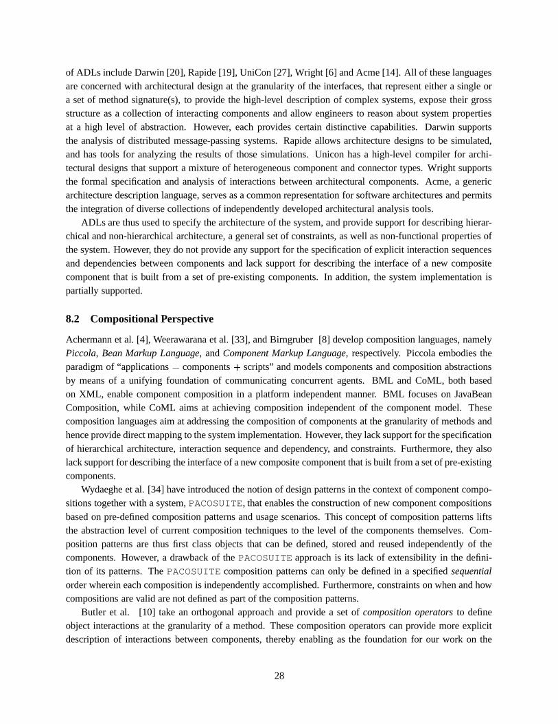
of ADLs include Darwin [20], Rapide [19], UniCon [27], Wright [6] and Acme [14]. All of these languagesare concerned with architectural design at the granularity of the interfaces, that represent either a single ora set of method signature(s), to provide the high-level description of complex systems, expose their grossstructure as a collection of interacting components and allow engineers to reason about system propertiesat a high level of abstraction. However, each provides certain distinctive capabilities. Darwin supportsthe analysis of distributed message-passing systems. Rapide allows architecture designs to be simulated,and has tools for analyzing the results of those simulations. Unicon has a high-level compiler for archi-tectural designs that support a mixture of heterogeneous component and connector types. Wright supportsthe formal specification and analysis of interactions between architectural components. Acme, a genericarchitecture description language, serves as a common representation for software architectures and permitsthe integration of diverse collections of independently developed architectural analysis tools.
ADLs are thus used to specify the architecture of the system, and provide support for describing hierar-chical and non-hierarchical architecture, a general set of constraints, as well as non-functional properties ofthe system. However, they do not provide any support for the specification of explicit interaction sequencesand dependencies between components and lack support for describing the interface of a new compositecomponent that is built from a set of pre-existing components. In addition, the system implementation ispartially supported.
8.2 Compositional Perspective
Achermann et al. [4], Weerawarana et al. [33], and Birngruber [8] develop composition languages, namelyPiccola, Bean Markup Language, and Component Markup Language, respectively. Piccola embodies theparadigm of “applications � components � scripts” and models components and composition abstractionsby means of a unifying foundation of communicating concurrent agents. BML and CoML, both basedon XML, enable component composition in a platform independent manner. BML focuses on JavaBeanComposition, while CoML aims at achieving composition independent of the component model. Thesecomposition languages aim at addressing the composition of components at the granularity of methods andhence provide direct mapping to the system implementation. However, they lack support for the specificationof hierarchical architecture, interaction sequence and dependency, and constraints. Furthermore, they alsolack support for describing the interface of a new composite component that is built from a set of pre-existingcomponents.
Wydaeghe et al. [34] have introduced the notion of design patterns in the context of component compo-sitions together with a system, PACOSUITE, that enables the construction of new component compositionsbased on pre-defined composition patterns and usage scenarios. This concept of composition patterns liftsthe abstraction level of current composition techniques to the level of the components themselves. Com-position patterns are thus first class objects that can be defined, stored and reused independently of thecomponents. However, a drawback of the PACOSUITE approach is its lack of extensibility in the defini-tion of its patterns. The PACOSUITE composition patterns can only be defined in a specified sequentialorder wherein each composition is independently accomplished. Furthermore, constraints on when and howcompositions are valid are not defined as part of the composition patterns.
Butler et al. [10] take an orthogonal approach and provide a set of composition operators to defineobject interactions at the granularity of a method. These composition operators can provide more explicitdescription of interactions between components, thereby enabling as the foundation for our work on the
28

composition primitives.Raje et al. [25] introduce Uniframe that aims to achieve interoperation of heterogeneous and distributed
software components; and provides a meta component model that allows access to various component mod-els, and supports the integration and validation of quality of service on an individual component. TheUniFrame approach also facilitates the use of generative rules for assembling components out of availablechoices. However, Uniframe does not support the generation of components and three incompatiblities(syntactic, semantic and design).
Oberleitner et al. [23] have developed the Vienna Component Framework (VCF), a Java based classframework that allows the access of components across different models and the construction of new com-ponents in a platform independent way using its unified component model. VCF also provides a genericprogramming model to built new components using the regular Java classes where these Java classes andtheir source code are used to generate source code for any component model. Consequently, the draw-backs of object-oriented languages still remain. Nor does VCF handle the syntactic, semantic, and designincompatibilities.
Furthermore, we can also draw many parallels between the CoCo composition model implementationand our previous work, SERF [11, 12]. We have previously developed a framework, SERF, that providesflexibility, extensibility and re-usability in the context of schema evolution for object-oriented databasesystems. The SERF framework was targeted to address the limitation of other schema evolution approachesmost of which provided a fixed taxonomy of schema evolution operations. The SERF approach is basedon the hypothesis that complex schema evolution transformations can be broken down into a sequence ofbasic evolution primitives, where each basic primitive is a correctness-preserving atomic operation withfixed semantics.
9 Conclusions and Future Work
It is essential to recognize the role and importance of compositions in component-based software develop-ment. Compositions are not only the enabling mechanism for thecomponent-based software construction, but are also a valuable reusable commodity that can provide dis-ciplined pattern based software development. In recognition of this, our work makes the following con-tributions. It provides, to the best of our knowledge, the first attempt at the standardization of componentcompositions elevating compositions to first class citizenship status. We provide a CoCo composition modelthat is both flexible and extensible, allowing developers to extend the standard to include at a later time othercomposition styles of component-based development. The key to this composition model extensibility is ourmeta-layer approach to composition, wherein multiple instances of the composition model constituents (in-stance, interface and association) can be described using XML Schemas. At the lowest level, compositionscripts can be described using the composition model implementation to describe an actual composition oftwo or more components. A composition script written in XML documents conforms to an instance of thecomposition model specified by an XML Schema, which in turn conforms to the general guidelines of thecomposition model.
Much of our work thus far has focused on the description of the composition model and on makingtransparent any incompatibilities at the time of composition development. And while we have taken initialsteps to address incompatibilities between the components at deployment time, there is much work to bedone in that area. For example, while we can currently handle platform incompatibilities, we cannot ade-
29
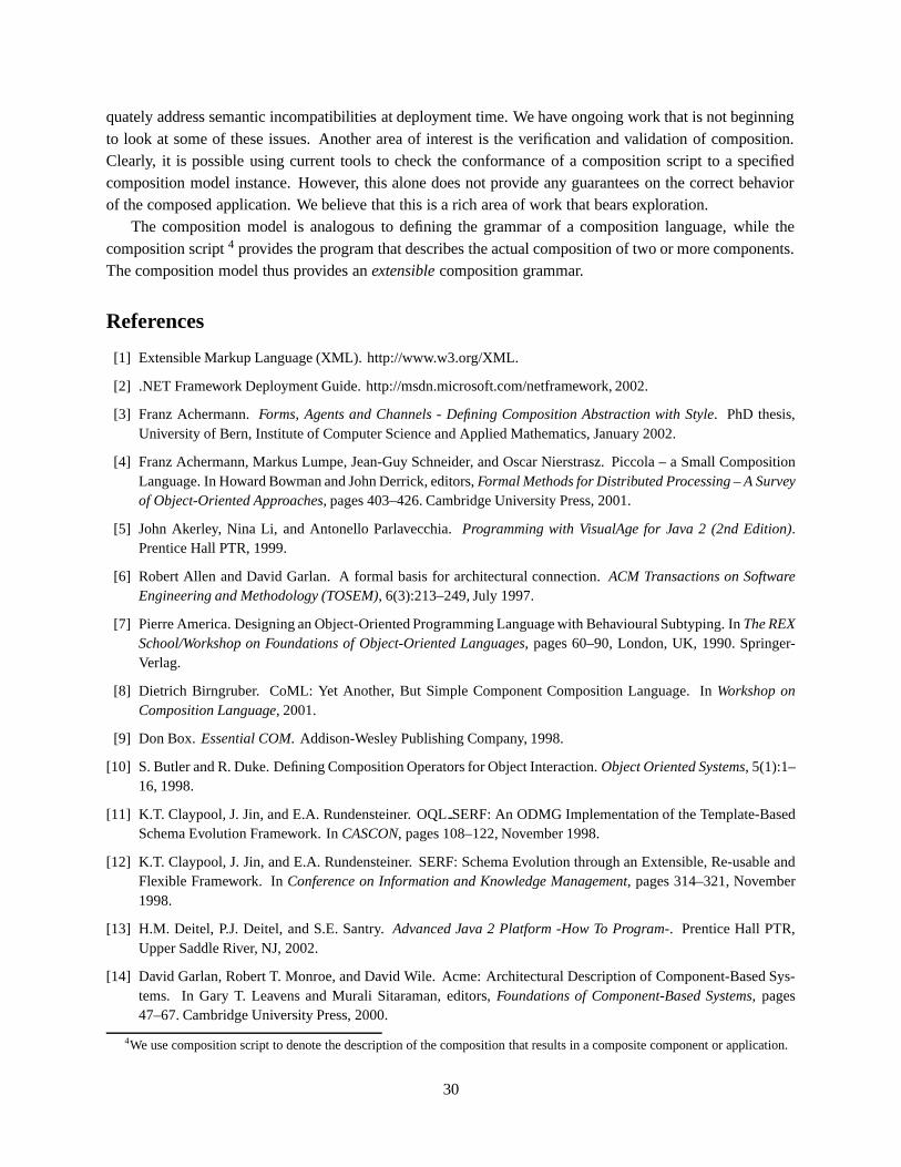
quately address semantic incompatibilities at deployment time. We have ongoing work that is not beginningto look at some of these issues. Another area of interest is the verification and validation of composition.Clearly, it is possible using current tools to check the conformance of a composition script to a specifiedcomposition model instance. However, this alone does not provide any guarantees on the correct behaviorof the composed application. We believe that this is a rich area of work that bears exploration.
The composition model is analogous to defining the grammar of a composition language, while thecomposition script 4 provides the program that describes the actual composition of two or more components.The composition model thus provides an extensible composition grammar.
References
[1] Extensible Markup Language (XML). http://www.w3.org/XML.
[2] .NET Framework Deployment Guide. http://msdn.microsoft.com/netframework, 2002.
[3] Franz Achermann. Forms, Agents and Channels - Defining Composition Abstraction with Style. PhD thesis,University of Bern, Institute of Computer Science and Applied Mathematics, January 2002.
[4] Franz Achermann, Markus Lumpe, Jean-Guy Schneider, and Oscar Nierstrasz. Piccola – a Small CompositionLanguage. In Howard Bowman and John Derrick, editors, Formal Methods for Distributed Processing – A Surveyof Object-Oriented Approaches, pages 403–426. Cambridge University Press, 2001.
[5] John Akerley, Nina Li, and Antonello Parlavecchia. Programming with VisualAge for Java 2 (2nd Edition).Prentice Hall PTR, 1999.
[6] Robert Allen and David Garlan. A formal basis for architectural connection. ACM Transactions on SoftwareEngineering and Methodology (TOSEM), 6(3):213–249, July 1997.
[7] Pierre America. Designing an Object-Oriented Programming Language with Behavioural Subtyping. In The REXSchool/Workshop on Foundations of Object-Oriented Languages, pages 60–90, London, UK, 1990. Springer-Verlag.
[8] Dietrich Birngruber. CoML: Yet Another, But Simple Component Composition Language. In Workshop onComposition Language, 2001.
[9] Don Box. Essential COM. Addison-Wesley Publishing Company, 1998.
[10] S. Butler and R. Duke. Defining Composition Operators for Object Interaction. Object Oriented Systems, 5(1):1–16, 1998.
[11] K.T. Claypool, J. Jin, and E.A. Rundensteiner. OQL SERF: An ODMG Implementation of the Template-BasedSchema Evolution Framework. In CASCON, pages 108–122, November 1998.
[12] K.T. Claypool, J. Jin, and E.A. Rundensteiner. SERF: Schema Evolution through an Extensible, Re-usable andFlexible Framework. In Conference on Information and Knowledge Management, pages 314–321, November1998.
[13] H.M. Deitel, P.J. Deitel, and S.E. Santry. Advanced Java 2 Platform -How To Program-. Prentice Hall PTR,Upper Saddle River, NJ, 2002.
[14] David Garlan, Robert T. Monroe, and David Wile. Acme: Architectural Description of Component-Based Sys-tems. In Gary T. Leavens and Murali Sitaraman, editors, Foundations of Component-Based Systems, pages47–67. Cambridge University Press, 2000.
4We use composition script to denote the description of the composition that results in a composite component or application.
30

[15] Thomas Gschwind, Johann Oberleitner, and Mehdi Jazayeri. Dynamic Component Extension to Support Cross-Platform Development. Technical Report TUV-1841-2002-19, Technische Universitt Wien, 2002.
[16] George T. Heineman and William T. Councill. Component-based Software Engineering. Addison-Wesley Pub-lishing Company, Reading, Massachusetts, 2001.
[17] Jun-Jang Jeng and Betty H. C. Cheng. Specification Matching for Software Reuse: A Foundation*. In Proceed-ings of the 1995 Symposium on Software reusability. ACM Press, 1995.
[18] Henri Jubin and the Jalapeno Team. JAVABEANS by Example. Prentice Hall PTR, Upper Saddle River, NJ, 1998.
[19] David C. Luckham, John L. Kenney, Larry M. Augustin, James Vera, Doug Bryan, and Walter Mann. Spec-ification and Analysis of System Architecture Using Rapide. IEEE Transactions on Software Engineering,21(4):336–355, 1995.
[20] J. Magee, N. Dulay, S. Eisenbach, and J. Kramer. Specifying Distributed Software Architectures. In W. Schaferand P. Botella, editors, Proc. 5th European Software Engineering Conf. (ESEC 95), volume 989, pages 137–153,Sitges, Spain, 1995. Springer-Verlag, Berlin.
[21] Bertrand Meyer. Object-Oriented Software Construction. Prentice Hall PTR, Upper Saddle River, NJ, 1997.
[22] Hans Muller and Mark Davidson. JavaBeans Specification: Getting Listeners from JavaBeans.http://java.sun.com/products/javabeans, 1996.
[23] Johann Oberleitner, Thomas Gschwind, and Mehdi Jazayeri. The Vienna Component Framework EnablingComposition Across Component Models. In The 25th International Conference on Software Engineering, 2003.
[24] James J. Odell. Six Different Kinds of Composition. Object-Oriented Programming, 5(8), January 1994.
[25] Rajee R. Raje, Mikhail Auguston, Barrett R. Bryant, Andrew M. Olson, and Carol Burt. A Unified Approach forthe Integration of Distributed Heterogeneous Software Components. In The Monterey Workshop on EngineeringAutomation for Software Intensive System Integration, pages 109–119, 2001.
[26] Bill Roth. An Introduction to Enterprise JavaBeans Technology. http://java.sun.com/products/ejb, 1998.
[27] Mary Shaw, Robert DeLine, Daniel V. Klein, Theodore L. Ross, David M. Young, and Gregory Zelesnik. Ab-stractions for Software Architecture and Tools to Support Them. Software Engineering, 21(4):314–335, 1995.
[28] J. Siegel. CORBA: Fundamentals and Programming for the 21st century. John Wiley, New York, 1996.
[29] Beth Stearns. Using Forte for Java to Develop and Deploy Enterprise Beans.http://java.sun.com/developer/technicalArticles/WebServices/ffjweb/, 2001.
[30] Naiyana Tansalarak and Kajal T. Claypool. XCompose: An XML-based Component Composition Framework.http://www.cs.uml.edu/dsl/XCompose, 2003.
[31] A. Vallecillo, J. Hernandez, and J. Troya. Component Interoperability. Technical Report ITI-2000-37, De-partmento de Lenguajes y Ciencias de la Computacion, University of Malaga, July 2000. Available athttp://www.lcc.uma.es/ � av/Publicaciones/00/Interoperability.pdf.
[32] Eric van der Vlist. XML Schema. O’Reilly and Associates, 2002.
[33] Sanjiva Weerawarana, Francisco Curbera, Mattew J. Duftler, David A. Epstein, and Joseph Kesselman. BeanMarkup Language: A Composition Language for JavaBeans Components. In Proceedings of the 6th USENIXConference on Object-Oriented Technology System (COOTS 2001), pages 173–187, January 2001.
[34] Bart Wydaeghe. PACOSUITE: Component Composition Based on Composition Patterns and Usage Scenarios.PhD thesis, VRIJE University Brussel, November 2001.
31

[35] Daniil Yakimovich, Guilherme H. Travassos, and Victor R. Basili. A Classification of Software ComponentsIncompatibilities for COTS Integration. http://sel.gsfc.nasa.gov/website/research/tech-study.htm.
[36] Amy Moormann Zaremski and Jeannette M. Wing. Signature Matching: a Tool for Using Software Libraries. InACM Transactions on Software Engineering and Methodology (TOSEM). ACM Press, 1995.
[37] Amy Moormann Zaremski and Jeannette M. Wing. Specification Matching of Software Components. In ACMTransactions on Software Engineering and Methodology (TOSEM). ACM Press, 1997.
32