cocentric systemc compiler rtl user and modeling...
TRANSCRIPT

Comments?E-mail your comments about Synopsysdocumentation to [email protected]
CoCentric®
SystemC™ CompilerRTL User and Modeling GuideVersion U-2003.06, June 2003

ii
Copyright Notice and Proprietary InformationCopyright 2003 Synopsys, Inc. All rights reserved. This software and documentation contain confidential and proprietaryinformation that is the property of Synopsys, Inc. The software and documentation are furnished under a license agreement andmay be used or copied only in accordance with the terms of the license agreement. No part of the software and documentation maybe reproduced, transmitted, or translated, in any form or by any means, electronic, mechanical, manual, optical, or otherwise,without prior written permission of Synopsys, Inc., or as expressly provided by the license agreement.
Right to Copy DocumentationThe license agreement with Synopsys permits licensee to make copies of the documentation for its internal use only.Each copy shall include all copyrights, trademarks, service marks, and proprietary rights notices, if any. Licensee mustassign sequential numbers to all copies. These copies shall contain the following legend on the cover page:
“This document is duplicated with the permission of Synopsys, Inc., for the exclusive use of__________________________________________ and its employees. This is copy number __________.”
Destination Control StatementAll technical data contained in this publication is subject to the export control laws of the United States of America.Disclosure to nationals of other countries contrary to United States law is prohibited. It is the reader’s responsibility todetermine the applicable regulations and to comply with them.
DisclaimerSYNOPSYS, INC., AND ITS LICENSORS MAKE NO WARRANTY OF ANY KIND, EXPRESS OR IMPLIED, WITHREGARD TO THIS MATERIAL, INCLUDING, BUT NOT LIMITED TO, THE IMPLIED WARRANTIES OFMERCHANTABILITY AND FITNESS FOR A PARTICULAR PURPOSE.
Registered Trademarks (®)Synopsys, AMPS, Arcadia, C Level Design, C2HDL, C2V, C2VHDL, Cadabra, Calaveras Algorithm, CATS, CoCentric,COSSAP, CSim, DelayMill, Design Compiler, DesignPower, DesignWare, Device Model Builder, EPIC, Formality,HSPICE, Hypermodel, I, iN-Phase, in-Sync, InSpecs, LEDA, MAST, Meta, Meta-Software, ModelAccess, ModelExpress,ModelTools, PathBlazer, PathMill, Photolynx, Physical Compiler, PowerArc, PowerMill, PrimeTime, RailMill, Raphael,RapidScript, Saber, SiVL, SmartLogic, SNUG, SolvNet, Stream Driven Simulator, Superlog, System Compiler, Testify,TetraMAX, TimeMill, TMA, Vera, and Virtual Stepper are registered trademarks of Synopsys, Inc.
Trademarks (™)abraCAD, abraMAP, Active Parasitics, AFGen, Apollo, Apollo II, Apollo-DPII, Apollo-GA, ApolloGAII, Astro, Astro-Rail,Astro-Xtalk, Aurora, AvanTestchip, AvanWaves, BCView, Behavioral Compiler, BOA, BRT, Cedar, ChipPlanner, CircuitAnalysis, Columbia, Columbia-CE, Comet 3D, Cosmos, CosmosEnterprise, CosmosLE, CosmosScope, CosmosSE,Cyclelink, Davinci, DC Expert, DC Expert Plus, DC Professional, DC Ultra, DC Ultra Plus, Design Advisor, DesignAnalyzer, DesignerHDL, DesignTime, DFM-Workbench, DFT Compiler, Direct RTL, Direct Silicon Access, DW8051,DWPCI, Dynamic Model Switcher, Dynamic-Macromodeling, ECL Compiler, ECO Compiler, EDAnavigator, Encore,Encore PQ, Evaccess, ExpressModel, Floorplan Manager, Formal Model Checker, FormalVera, FoundryModel, FPGACompiler II, FPGA Express, Frame Compiler, Frameway, Galaxy, Gatran, HDL Advisor, HDL Compiler, Hercules,Hercules-Explorer, Hercules-II, Hierarchical Optimization Technology, High Performance Option, HotPlace,HSPICE-Link, iN-Tandem, Integrator, Interactive Waveform Viewer, iQBus, Jupiter, Jupiter-DP, JupiterXT,JupiterXT-ASIC, JVXtreme, Liberty, Libra-Passport, Libra-Visa, Library Compiler, LRC, Mars, Mars-Rail, Mars-Xtalk,Medici, Metacapture, Metacircuit, Metamanager, Metamixsim, Milkyway, ModelSource, Module Compiler, MS-3200,MS-3400, NanoSim, Nova Product Family, Nova-ExploreRTL, Nova-Trans, Nova-VeriLint, Nova-VHDLlint, OpenVera,Optimum Silicon, Orion_ec, Parasitic View, Passport, Planet, Planet-PL, Planet-RTL, Polaris, Polaris-CBS, Polaris-MT,Power Compiler, PowerCODE, PowerGate, ProFPGA, Progen, Prospector, Proteus OPC, Protocol Compiler, PSMGen,Raphael-NES, RoadRunner, RTL Analyzer, Saturn, ScanBand, Schematic Compiler, Scirocco, Scirocco-i, ShadowDebugger, Silicon Blueprint, Silicon Early Access, SinglePass-SoC, Smart Extraction, SmartLicense, SmartModelLibrary, Softwire, Source-Level Design, Star, Star-DC, Star-MS, Star-MTB, Star-Power, Star-Rail, Star-RC, Star-RCXT,Star-Sim, Star-Sim XT, Star-Time, Star-XP, SWIFT, Taurus, Taurus-Device, Taurus-Layout, Taurus-Lithography,Taurus-OPC, Taurus-Process, Taurus-Topography, Taurus-Visual, Taurus-Workbench, The Power in Semiconductors,TimeSlice, TimeTracker, Timing Annotator, TopoPlace, TopoRoute, Trace-On-Demand, True-Hspice, TSUPREM-4,TymeWare, VCS, VCS Express, VCSi, Venus, Verification Portal, VFormal, VHDL Compiler, VHDL System Simulator,VirSim, and VMC are trademarks of Synopsys, Inc.
Service Marks (SM)DesignSphere, MAP-in, SVP Café, and TAP-in are service marks of Synopsys, Inc.
SystemC is a trademark of the Open SystemC Initiative and is used under license.AMBA is a trademark of ARM Limited. ARM is a registered trademark of ARM Limited.All other product or company names may be trademarks of their respective owners.
Printed in the U.S.A.
Document Order Number: 37582-000 QACoCentric SystemC Compiler RTL User and Modeling Guide, Version U-2003.06

iii
Contents
What’s New in This Release . . . . . . . . . . . . . . . . . . . . . . . . . . . . . xii
About This Guide. . . . . . . . . . . . . . . . . . . . . . . . . . . . . . . . . . . . . . xiii
Customer Support . . . . . . . . . . . . . . . . . . . . . . . . . . . . . . . . . . . . . xvi
1. Using SystemC Compiler for RTL Synthesis
Synthesis With SystemC Compiler . . . . . . . . . . . . . . . . . . . . . . . . . 1-3
Choosing the Right Abstraction for Synthesis . . . . . . . . . . . . . . 1-4Identifying Attributes Suitable for RTL Synthesis . . . . . . . . . 1-4Identifying Attributes Suitable for Behavioral Synthesis . . . . 1-5
RTL Design for Synthesis Overview . . . . . . . . . . . . . . . . . . . . . . . . 1-6
Inputs and Outputs for RTL Synthesis. . . . . . . . . . . . . . . . . . . . . . . 1-7
RTL Description . . . . . . . . . . . . . . . . . . . . . . . . . . . . . . . . . . . . . 1-8
Technology Library. . . . . . . . . . . . . . . . . . . . . . . . . . . . . . . . . . . 1-8
Synthetic Library . . . . . . . . . . . . . . . . . . . . . . . . . . . . . . . . . . . . 1-8
Outputs From SystemC Compiler . . . . . . . . . . . . . . . . . . . . . . . 1-9
Synthesizing a SystemC Design in a Single File. . . . . . . . . . . . . . . 1-9
Starting SystemC Compiler . . . . . . . . . . . . . . . . . . . . . . . . . . . . 1-11

iv
Elaborating Your Design . . . . . . . . . . . . . . . . . . . . . . . . . . . . . . 1-11
Analyzing and Elaborating a Design With thecompile_systemc Command . . . . . . . . . . . . . . . . . . . . . . . . 1-12Creating an Elaborated .db File for Synthesis . . . . . . . . . . . 1-13Creating an RTL HDL Description . . . . . . . . . . . . . . . . . . . . 1-13
Designating a Directory and Library for the Design . . . . . . . . . . 1-16
Setting the Clock Period. . . . . . . . . . . . . . . . . . . . . . . . . . . . . . . 1-17
Compiling and Writing the Gate-Level Netlist . . . . . . . . . . . . . . 1-18
Generating Summary Reports . . . . . . . . . . . . . . . . . . . . . . . . . . 1-18
Synthesizing a Design With Multiple RTL Files . . . . . . . . . . . . . . . . 1-19
Analyzing and Elaborating Multiple RTL Files . . . . . . . . . . . . . . 1-20Setting the Clock Period . . . . . . . . . . . . . . . . . . . . . . . . . . . . 1-21Linking the .db Files . . . . . . . . . . . . . . . . . . . . . . . . . . . . . . . 1-21
Compiling and Writing the Gate-Level Netlist . . . . . . . . . . . . . . 1-22
Synthesizing a Design With Integrated Behavioral andRTL Modules . . . . . . . . . . . . . . . . . . . . . . . . . . . . . . . . . . . . . . . 1-22
Passing Parameters to a Module. . . . . . . . . . . . . . . . . . . . . . . . . . . 1-23
Limitations for Passing Parameters . . . . . . . . . . . . . . . . . . . . . . 1-24
Names of Parameterized Modules. . . . . . . . . . . . . . . . . . . . . . . 1-24
Synthesizing a Design With an Instantiated HDL Model . . . . . . . . . 1-26
Synthesizing a Design With an Instantiated DesignWareComponent . . . . . . . . . . . . . . . . . . . . . . . . . . . . . . . . . . . . . . . . 1-28
2. Creating SystemC Modules for Synthesis
Defining Modules and Processes . . . . . . . . . . . . . . . . . . . . . . . . . . 2-2
Modules . . . . . . . . . . . . . . . . . . . . . . . . . . . . . . . . . . . . . . . . . . . 2-2
v
Processes . . . . . . . . . . . . . . . . . . . . . . . . . . . . . . . . . . . . . . . . . 2-3Registering a Process . . . . . . . . . . . . . . . . . . . . . . . . . . . . . 2-3Triggering Execution of a Process . . . . . . . . . . . . . . . . . . . . 2-4Reading and Writing in a Process . . . . . . . . . . . . . . . . . . . . 2-4Types of Processes . . . . . . . . . . . . . . . . . . . . . . . . . . . . . . . 2-4
Creating a Module . . . . . . . . . . . . . . . . . . . . . . . . . . . . . . . . . . . . . . 2-6
Module Header File . . . . . . . . . . . . . . . . . . . . . . . . . . . . . . . . . . 2-6Module Syntax . . . . . . . . . . . . . . . . . . . . . . . . . . . . . . . . . . . 2-6
Module Ports . . . . . . . . . . . . . . . . . . . . . . . . . . . . . . . . . . . . . . . 2-7Port Syntax. . . . . . . . . . . . . . . . . . . . . . . . . . . . . . . . . . . . . . 2-8Port Data Types . . . . . . . . . . . . . . . . . . . . . . . . . . . . . . . . . . 2-8
Signals . . . . . . . . . . . . . . . . . . . . . . . . . . . . . . . . . . . . . . . . . . . . 2-8Signal Syntax . . . . . . . . . . . . . . . . . . . . . . . . . . . . . . . . . . . . 2-9Signal Data Types . . . . . . . . . . . . . . . . . . . . . . . . . . . . . . . . 2-10
Data Member Variables . . . . . . . . . . . . . . . . . . . . . . . . . . . . . . . 2-10
Assigning to Data Members in the Constructor . . . . . . . . . . . . . 2-11
Creating a Process in a Module. . . . . . . . . . . . . . . . . . . . . . . . . 2-11
Defining the Sensitivity List . . . . . . . . . . . . . . . . . . . . . . . . . . . . 2-12Defining a Level-Sensitive Process . . . . . . . . . . . . . . . . . . . 2-12Incomplete Sensitivity Lists . . . . . . . . . . . . . . . . . . . . . . . . . 2-13Defining an Edge-Sensitive Process . . . . . . . . . . . . . . . . . . 2-14Limitations for Sensitivity Lists . . . . . . . . . . . . . . . . . . . . . . . 2-15Member Functions . . . . . . . . . . . . . . . . . . . . . . . . . . . . . . . . 2-15Implementing the Module . . . . . . . . . . . . . . . . . . . . . . . . . . . 2-16
Module Constructor . . . . . . . . . . . . . . . . . . . . . . . . . . . . . . . . . . 2-16Defining a Constructor With the SC_CTOR Macro . . . . . . . 2-16Registering a Process . . . . . . . . . . . . . . . . . . . . . . . . . . . . . 2-17
vi
Defining a Constructor With the SC_HAS_PROCESSMacro . . . . . . . . . . . . . . . . . . . . . . . . . . . . . . . . . . . . . . . 2-18
Reading and Writing Ports and Signals . . . . . . . . . . . . . . . . . . . 2-28
Reading and Writing Bits of Ports and Signals . . . . . . . . . . . . . 2-29
Signal and Port Assignments. . . . . . . . . . . . . . . . . . . . . . . . . . . 2-30
Variable Assignment . . . . . . . . . . . . . . . . . . . . . . . . . . . . . . . . . 2-31
Creating a Module With a Single SC_METHOD Process . . . . . . . . 2-32
Creating a Module With Multiple SC_METHOD Processes . . . . . . 2-34
Creating a Hierarchical RTL Module . . . . . . . . . . . . . . . . . . . . . . . . 2-38
The Basics of Hierarchical Module Creation . . . . . . . . . . . . . . . 2-38
Creating an Integrated RTL and Behavioral Module . . . . . . . . . . . . 2-40
Specifying Preserved Functions and ImplementingDesignWare Components . . . . . . . . . . . . . . . . . . . . . . . . . . . . . 2-43
Defining a Preserved Function. . . . . . . . . . . . . . . . . . . . . . . . . . 2-43
Verilog HDL From a Preserved Function . . . . . . . . . . . . . . . . . . 2-46
Mapping a Function to a Synthetic Operator . . . . . . . . . . . . . . . 2-47
Verilog HDL From a Function Mapped to a DesignWareComponent. . . . . . . . . . . . . . . . . . . . . . . . . . . . . . . . . . . . . . 2-50
3. Using the Synthesizable Subset
Converting to a Synthesizable Subset. . . . . . . . . . . . . . . . . . . . . . . 3-2
Excluding Nonsynthesizable Code . . . . . . . . . . . . . . . . . . . . . . 3-2
SystemC and C++ Synthesizable Subsets . . . . . . . . . . . . . . . . 3-3Nonsynthesizable SystemC Constructs . . . . . . . . . . . . . . . . 3-4Nonsynthesizable C/C++ Constructs . . . . . . . . . . . . . . . . . . 3-5
Modifying Data for Synthesis. . . . . . . . . . . . . . . . . . . . . . . . . . . . . . 3-8

vii
Synthesizable Data Types . . . . . . . . . . . . . . . . . . . . . . . . . . . . . 3-9
Nonsynthesizable Data Types . . . . . . . . . . . . . . . . . . . . . . . . . . 3-9
Recommended Data Types for Synthesis . . . . . . . . . . . . . . . . . 3-10
SystemC to VHDL Data Type Conversion . . . . . . . . . . . . . . . . . 3-12
Using SystemC Data Types . . . . . . . . . . . . . . . . . . . . . . . . . . . . 3-13Fixed-Precision and Arbitrary-Precision Data Type
Operators . . . . . . . . . . . . . . . . . . . . . . . . . . . . . . . . . . . . 3-13Concatenating Variables . . . . . . . . . . . . . . . . . . . . . . . . . . . 3-14Using a Variable to Read and Write Bits . . . . . . . . . . . . . . . 3-15
Using Constants. . . . . . . . . . . . . . . . . . . . . . . . . . . . . . . . . . . . . 3-16
Using Enumerated Data Types . . . . . . . . . . . . . . . . . . . . . . . . . 3-17
Using Aggregate Data Types . . . . . . . . . . . . . . . . . . . . . . . . . . . 3-17
Data Members of a Module . . . . . . . . . . . . . . . . . . . . . . . . . . . . 3-18
Assigning to Data Members in the Constructor . . . . . . . . . . . . . 3-20
Recommendations About Modification for Synthesis . . . . . . . . . . . 3-20
4. RTL Coding Guidelines
Register Inference . . . . . . . . . . . . . . . . . . . . . . . . . . . . . . . . . . . . . . 4-2
Flip-Flop Inference . . . . . . . . . . . . . . . . . . . . . . . . . . . . . . . . . . . 4-2Simple D Flip-Flop . . . . . . . . . . . . . . . . . . . . . . . . . . . . . . . . 4-2D Flip-Flop With an Active-High Asynchronous Set or
Reset . . . . . . . . . . . . . . . . . . . . . . . . . . . . . . . . . . . . . . . 4-4D Flip-Flop With an Active-Low Asynchronous Set
or Reset . . . . . . . . . . . . . . . . . . . . . . . . . . . . . . . . . . . . . 4-5D Flip-Flop With Active-High Asynchronous Set and
Reset . . . . . . . . . . . . . . . . . . . . . . . . . . . . . . . . . . . . . . . 4-6D Flip-Flop With Synchronous Set or Reset. . . . . . . . . . . . . 4-7Inferring JK Flip-Flops . . . . . . . . . . . . . . . . . . . . . . . . . . . . . 4-9

viii
Inferring Toggle Flip-Flops . . . . . . . . . . . . . . . . . . . . . . . . . . 4-12
Latch Inference . . . . . . . . . . . . . . . . . . . . . . . . . . . . . . . . . . . . . 4-14Inferring a D Latch From an If Statement . . . . . . . . . . . . . . . 4-14Inferring a Latch From a Switch Statement . . . . . . . . . . . . . 4-18Priority Encoding . . . . . . . . . . . . . . . . . . . . . . . . . . . . . . . . . 4-24Active-Low Set and Reset . . . . . . . . . . . . . . . . . . . . . . . . . . 4-26Active-High Set and Reset . . . . . . . . . . . . . . . . . . . . . . . . . . 4-27D Latch With an Asynchronous Set and Reset . . . . . . . . . . 4-29D Latch With an Asynchronous Set . . . . . . . . . . . . . . . . . . . 4-30D Latch With an Asynchronous Reset . . . . . . . . . . . . . . . . . 4-31
Understanding the Limitations of Register Inference . . . . . . . . . 4-32
Instantiating a Component as a Black Box . . . . . . . . . . . . . . . . 4-32
Multibit Inference . . . . . . . . . . . . . . . . . . . . . . . . . . . . . . . . . . . . . . . 4-35
Inferring Multibit . . . . . . . . . . . . . . . . . . . . . . . . . . . . . . . . . . . . . 4-36
Preventing Multibit Inference . . . . . . . . . . . . . . . . . . . . . . . . . . . 4-38
Multiplexer Inference . . . . . . . . . . . . . . . . . . . . . . . . . . . . . . . . . . . . 4-39
Inferring Multiplexers From a Block of Code . . . . . . . . . . . . . . . 4-40
Preventing Multiplexer Inference . . . . . . . . . . . . . . . . . . . . . . . . 4-42
Inferring a Multiplexer From a Specific Switch Statement . . . . . 4-44
Understanding the Limitations of Multiplexer Inference . . . . . . . 4-46
Three-State Inference . . . . . . . . . . . . . . . . . . . . . . . . . . . . . . . . . . . 4-47
Simple Three-State Inference . . . . . . . . . . . . . . . . . . . . . . . . . . 4-47Three-State Driver for Bus . . . . . . . . . . . . . . . . . . . . . . . . . . 4-49
Registered Three-State Drivers . . . . . . . . . . . . . . . . . . . . . . . . . 4-50
Understanding the Limitations of Three-State Inference . . . . . . 4-53
Loops. . . . . . . . . . . . . . . . . . . . . . . . . . . . . . . . . . . . . . . . . . . . . . . . 4-53
ix
Loop Unrolling Criteria . . . . . . . . . . . . . . . . . . . . . . . . . . . . . . . . 4-54
Unrolled Loop. . . . . . . . . . . . . . . . . . . . . . . . . . . . . . . . . . . . . . . 4-55
for Loop Comma Operator . . . . . . . . . . . . . . . . . . . . . . . . . . . . . 4-56
Dead Loops . . . . . . . . . . . . . . . . . . . . . . . . . . . . . . . . . . . . . . . . 4-56
Infinite Loops . . . . . . . . . . . . . . . . . . . . . . . . . . . . . . . . . . . . . . . 4-56
State Machines . . . . . . . . . . . . . . . . . . . . . . . . . . . . . . . . . . . . . . . . 4-57
State Machine With a Common Computation Process . . . . . . . 4-59
State Machine With Separate Computation Processes . . . . . . . 4-60
Moore State Machine. . . . . . . . . . . . . . . . . . . . . . . . . . . . . . . . . 4-62
Defining a State Vector Variable . . . . . . . . . . . . . . . . . . . . . . . . 4-63
Appendix A. Compiler Directives
Synthesis Compiler Directives. . . . . . . . . . . . . . . . . . . . . . . . . . . . . A-2
Line Label Compiler Directive . . . . . . . . . . . . . . . . . . . . . . . . . . A-3
Multibit Inference Compiler Directives . . . . . . . . . . . . . . . . . . . . A-3
Multiplexer Inference Compiler Directives . . . . . . . . . . . . . . . . . A-4
Loop Unrolling Compiler Directive . . . . . . . . . . . . . . . . . . . . . . . A-5
switch…case Compiler Directives . . . . . . . . . . . . . . . . . . . . . . . A-5Full Case . . . . . . . . . . . . . . . . . . . . . . . . . . . . . . . . . . . . . . . A-5Parallel Case . . . . . . . . . . . . . . . . . . . . . . . . . . . . . . . . . . . . A-6
State Vector Compiler Directive . . . . . . . . . . . . . . . . . . . . . . . . . A-6
Enumerated Data Type Compiler Directive . . . . . . . . . . . . . . . . A-8
Synthesis Off and On . . . . . . . . . . . . . . . . . . . . . . . . . . . . . . . . A-8
C/C++ Compiler Directives . . . . . . . . . . . . . . . . . . . . . . . . . . . . . . . A-9
C/C++ Line Label . . . . . . . . . . . . . . . . . . . . . . . . . . . . . . . . . . . . A-9
C/C++ Conditional Compilation . . . . . . . . . . . . . . . . . . . . . . . . . A-9
x
Appendix B. Examples
Count Zeros Combinational Version . . . . . . . . . . . . . . . . . . . . . . . . B-2
Count Zeros Sequential Version . . . . . . . . . . . . . . . . . . . . . . . . . . . B-3
FIR RTL Version . . . . . . . . . . . . . . . . . . . . . . . . . . . . . . . . . . . . . . . B-4
FIR RTL and Behavioral Integrated Version . . . . . . . . . . . . . . . . . . B-5
Drink Machine . . . . . . . . . . . . . . . . . . . . . . . . . . . . . . . . . . . . . . . . . B-7
Index

xi
Preface FIX ME!
This preface includes the following sections:
• What’s New in This Release
• About This Guide
• Customer Support

xii
Preface
What’s New in This Release
Information about new features, enhancements, and changes;known problems and limitations; and resolved Synopsys TechnicalAction Requests (STARs) is available in the SystemC CompilerRelease Notes in SolvNet.
To see the SystemC Compiler Release Notes,
1. Go to the Synopsys Web page at http://www.synopsys.com andclick SolvNet.
2. If prompted, enter your user name and password. (If you do nothave a Synopsys user name and password, follow theinstructions to register with SolvNet.)
3. Click Release Notes in the Main Navigation section, find theU-2003.06 Release Notes, then open the CoCentric SystemCCompiler Release Notes.

xiii
About This Guide
About This Guide
The CoCentric SystemC Compiler RTL User and Modeling Guidedescribes how to use SystemC Compiler for RTL synthesis. It alsodescribes how to develop or refine a SystemC RTL model forsynthesis with SystemC Compiler.
For information about SystemC, see the Open SystemC CommunityWeb site at http://www.systemc.org.
Audience
The CoCentric SystemC Compiler RTL User and Modeling Guide isfor designers with a basic knowledge of the SystemC Class Library,RTL design, and the C or C++ language and developmentenvironment.
Familiarity with one or more of the following Synopsys tools ishelpful:
• Synopsys Design Compiler
• Synopsys HDL Compiler for VHDL
• Synopsys HDL Compiler (Presto Verilog)
• Synopsys Scirocco VHDL Simulator
• Synopsys Verilog Compiled Simulator (VCS)

xiv
Preface
Related Publications
For additional information about SystemC Compiler, see
• Synopsys Online Documentation (SOLD), which is included withthe software for CD users or is available to download through theSynopsys Electronic Software Transfer (EST) system
• Documentation on the Web, which is available through SolvNetat http://solvnet.synopsys.com
• The Synopsys MediaDocs Shop, from which you can orderprinted copies of Synopsys documents, athttp://mediadocs.synopsys.com
You might also want to refer to the following documentation:
• The CoCentric SystemC Compiler Behavioral User and ModelingGuide, which provides information about how to synthesize arefined SystemC hardware behavioral module into an RTL or agate-level netlist. It also describes how to develop or refine abehavioral SystemC model for synthesis with SystemC Compiler.
• The CoCentric System Studio HDL CoSim User Guide, whichprovides information about cosimulating a system with mixedSystemC and HDL modules.
• The CoCentric SystemC Compiler Quick Reference, whichprovides a list of command with their options and a list ofvariables that affect the SystemC Compiler tool behavior.
• The SystemC documentation, available from the Open SystemCCommunity Web site at http://www.systemc.org.

xv
About This Guide
Conventions
The following conventions are used in Synopsys documentation.
Convention Description
Courier Indicates command syntax.
Courier italic Indicates a user-defined value in Synopsyssyntax, such as object_name. (A user-definedvalue that is not Synopsys syntax, such as auser-defined value in a Verilog or VHDLstatement, is indicated by regular text fontitalic.)
Courier bold Indicates user input—text you type verbatim—in Synopsys syntax and examples. (User inputthat is not Synopsys syntax, such as a username or password you enter in a GUI, isindicated by regular text font bold.)
[ ] Denotes optional parameters, such aspin1 [pin2 ... pinN]
| Indicates a choice among alternatives, such aslow | medium | high(This example indicates that you can enter oneof three possible values for an option:low, medium, or high.)
_ Connects terms that are read as a single termby the system, such asset_annotated_delay
Control-c Indicates a keyboard combination, such asholding down the Control key and pressing c.
\ Indicates a continuation of a command line.
/ Indicates levels of directory structure.
Edit > Copy Indicates a path to a menu command, such asopening the Edit menu and choosing Copy.

xvi
Preface
Customer Support
Customer support is available through SolvNet online customersupport and through contacting the Synopsys Technical SupportCenter. Customer training is available through the SynopsysCustomer Education Center.
Accessing SolvNet
SolvNet includes an electronic knowledge base of technical articlesand answers to frequently asked questions about Synopsys tools.SolvNet also gives you access to a wide range of Synopsys onlineservices, including software downloads, documentation on the Web,and “Enter a Call With the Support Center.”
To access SolvNet,
1. Go to the SolvNet Web page at http://solvnet.synopsys.com.
2. If prompted, enter your user name and password. (If you do nothave a Synopsys user name and password, follow theinstructions to register with SolvNet.)
If you need help using SolvNet, click SolvNet Help in the SupportResources section.

xvii
Customer Support
Contacting the Synopsys Technical Support Center
If you have problems, questions, or suggestions, you can contact theSynopsys Technical Support Center in the following ways:
• Open a call to your local support center from the Web by going tohttp://solvnet.synopsys.com (Synopsys user name andpassword required) and click “Enter a Call With the SupportCenter.”
• Send an e-mail message to [email protected].
• Telephone your local support center.
- Call (800) 245-8005 from within the continental United States.
- Call (650) 584-4200 from Canada.
- Find other local support center telephone numbers athttp://www.synopsys.com/support/support_ctr.

xviii
Preface

1-1
1Using SystemC Compiler for RTL Synthesis1
The CoCentric SystemC Compiler tool synthesizes a SystemCdescription with a behavioral module, RTL modules, or a mixedRTL-behavioral module into an HDL RTL module or a gate-levelnetlist. After synthesis, you can use the HDL RTL description or thenetlist as input to other Synopsys products such as the DesignCompiler and Physical Compiler tools.
This chapter describes the RTL synthesis process and thecommands you typically use, in the following sections:
• Synthesis With SystemC Compiler
• RTL Design for Synthesis Overview
• Inputs and Outputs for RTL Synthesis
• Synthesizing a SystemC Design in a Single File
• Synthesizing a Design With Multiple RTL Files
1-2
Chapter 1: Using SystemC Compiler for RTL Synthesis
• Synthesizing a Design With Integrated Behavioral and RTLModules
• Passing Parameters to a Module
• Synthesizing a Design With an Instantiated HDL Model
• Synthesizing a Design With an Instantiated DesignWareComponent

1-3
Synthesis With SystemC Compiler
Synthesis With SystemC Compiler
SystemC Compiler is a tool that can accept RTL and behavioralSystemC descriptions and perform behavioral or RTL synthesis, asrequired, to create a gate-level netlist. You can also use SystemCCompiler to create an RTL HDL description for simulation or to usewith other HDL tools in your flow. Figure 1-1 shows the behavioraland RTL synthesis paths to gate-level netlists.
Figure 1-1 Behavioral Synthesis Compared to RTL Synthesis
Behavioral
code
Gate-levelnetlist
RTL
code
Gate-levelnetlist
Behavioral Synthesis RTL Synthesis
Logicsynthesis
Logicsynthesis
HDL RTL(optional)
ToHDL-based
flow
HDL RTL(optional)
ToHDL-based
flow
SystemC
SystemCcompile_systemc
compile_systemc
Behavioralsynthesis
1-4
Chapter 1: Using SystemC Compiler for RTL Synthesis
Choosing the Right Abstraction for Synthesis
You can implement a hardware module by using RTL orbehavioral-level synthesis. An RTL model describes registers in yourdesign and the combinational logic between them. You specify thefunctionality of your system as a finite state machine (FSM) and adatapath. Because register updates are tied to a clock, the model iscycle accurate, both at the interfaces and internally. Internal cycleaccuracy means that you specify the clock cycle in which eachoperation is performed.
A behavioral model is an algorithmic description like a softwareprogram. Unlike a pure software program, however, the I/O behaviorof the model is described in a cycle-accurate fashion. Therefore, waitstatements are inserted into the algorithmic description to clearlydelineate clock cycle boundaries and when I/O happens. Unlike RTLdescriptions, the behavior is described algorithmically rather than interms of an FSM and a datapath.
Evaluate each design module by module, and consider eachmodule’s attributes, described in the following sections, to determinewhether RTL or behavioral synthesis is applicable.
Identifying Attributes Suitable for RTL Synthesis
Look for the following design attributes when identifying a hardwaremodule that is suitable for RTL synthesis with SystemC Compiler:
• The design is asynchronous.
• It is easier to conceive the design as an FSM and a datapath thanas an algorithm—for example, it is a microprocessor.
1-5
Synthesis With SystemC Compiler
• The design is very high performance, and the designer, therefore,needs complete control over the architecture.
• The design contains complex memory such as SDRAM orRAMBUS.
Identifying Attributes Suitable for Behavioral Synthesis
Look for the following design attributes when identifying a hardwaremodule that is suitable for behavioral synthesis with SystemCCompiler:
• It is easier to conceive the design as an algorithm than as anFSM and a datapath—for example, it is a fast Fourier transform,filter, an inverse quantization, or a digital signal processor.
• The design has a complex control flow—for example, it is anetwork processor.
• The design has memory accesses, and you need to synthesizeaccess to synchronous memory.
For information about behavioral synthesis and modeling, see theCoCentric SystemC Compiler Behavioral User and Modeling Guide.

1-6
Chapter 1: Using SystemC Compiler for RTL Synthesis
RTL Design for Synthesis Overview
A pure C/C++ model of your hardware describes only what thehardware is intended to do, without providing information about thehardware structure or architecture. Starting with a C/C++ model, firstmodify the design to create the hardware structure. To do this,
• Define the I/O ports for the hardware module
• Specify the internal structure as modules
• Specify the internal communication between the modules
For each block in the design, you start with a functional-levelSystemC model and change it into an RTL model for synthesis withSystemC Compiler. To modify the high-level model into an RTLmodel for synthesis, you
• Define the I/O in a cycle-accurate fashion
• Separate the control logic and datapath
• Determine the data-path architecture
• Define an explicit FSM for the control logic
A high-level SystemC model can contain abstract ports, which aretypes that are not readily translated to hardware. For each abstractport, define a port or a set of ports to replace each terminal of theabstract port, and replace all accesses to the abstract ports orterminals with accesses to the newly defined ports. For informationabout abstract ports, see the http://www.systemc.org web site.
Further information on designing for synthesis is provided in“Modifying Data for Synthesis” on page 3-8 and “RecommendationsAbout Modification for Synthesis” on page 3-20.

1-7
Inputs and Outputs for RTL Synthesis
Inputs and Outputs for RTL Synthesis
SystemC Compiler requires a SystemC RTL description andlibraries defining the components and technology that will be used toimplement the hardware. Figure 1-2 shows the flow into and out ofSystemC Compiler.
Figure 1-2 SystemC Compiler Input and Output Flow for RTLSynthesis
TechnologyLibrary
SystemC RTLDescription
SystemC Compiler
SyntheticLibrary
HDLnetlist
Elaborated
Synthesis
Logic andphysical synthesis
Post-synthesisverification
.db
RTL
Gate-levelnetlist
HDLCompiler
1-8
Chapter 1: Using SystemC Compiler for RTL Synthesis
RTL Description
Write the SystemC RTL description, using the SystemC ClassLibrary according to the guidelines in Chapter 2, “Creating SystemCModules for Synthesis,” Chapter 3, “Using the SynthesizableSubset,” and Chapter 4, “RTL Coding Guidelines.”
The RTL description is independent of the technology. UsingSystemC Compiler, you can change the target technology librarywithout modifying the RTL description.
The example designs used in this manual are described in AppendixB, “Examples.” The files for these examples are available in theSystemC Compiler installation in the $SYNOPSYS/doc/syn/ccsc/ccsc_examples directory.
Technology Library
A technology library is provided by ASIC vendors in Synopsys .dbdatabase format. It provides the area, timing, wire load models, andoperating conditions. You provide the path to your chosentechnology library for your design by defining the target_libraryvariable in dc_shell.
Sample technology libraries are provided in the SystemC Compilerinstallation at $SYNOPSYS/libraries/syn.
Synthetic Library
The DesignWare synthetic library is a technology-independentlibrary of logic components such as adders and multipliers. SystemCCompiler maps your design operators to the synthetic library logical

1-9
Synthesizing a SystemC Design in a Single File
components. You provide the path to your chosen synthetic librariesfor your design by defining the synthetic_library variable indc_shell.
The DesignWare synthetic libraries are provided in the SystemCCompiler installation at $SYNOPSYS/libraries/syn. The syntheticlibraries have names such as standard.sldb, dw01.sldb, anddw02.sldb. For information about the DesignWare libraries, see theDesignWare online documentation.
Outputs From SystemC Compiler
SystemC Compiler generates an elaborated .db file for input into theDesign Compiler tool. It also generates RTL HDL files that can beused in HDL-based flows.
Synthesizing a SystemC Design in a Single File
Figure 1-3 illustrates the primary commands you use to performsynthesis of a SystemC RTL design in a single file with SystemCCompiler and compile the design into gates (using DesignCompiler). The diagram also shows the inputs you provide and theoutputs produced at various stages.

1-10
Chapter 1: Using SystemC Compiler for RTL Synthesis
Figure 1-3 Single RTL Module Command Flow
The commands used in this chapter show the typical options youuse. For a full description of a command and all its options, see theSynopsys online man pages. How to access and use man pages isdescribed in Appendix A in the CoCentric SystemC CompilerBehavioral User and Modeling Guide.
compile_systemc
RTL SystemC description
Quality of results
Gate-level netlistcompile
Target and
librariessynthetic
SystemC Compiler with
OutputsCommandsInputs
Gate-level netlist
reports
.db file
HDL file
report_areareport_timing
create_clock
RTL HDL file
Design Compiler
Elaborated .db file

1-11
Synthesizing a SystemC Design in a Single File
Starting SystemC Compiler
SystemC Compiler is integrated into Design Compiler. Enter theSystemC Compiler commands at the dc_shell prompt or use theinclude command to run a script that contains the commands. Tostart dc_shell or dc_shell-t, enter the following at a UNIX prompt:
unix% dc_shell
or
unix% dc_shell-t
If this is the first time you are using SystemC Compiler, see AppendixA in the CoCentric SystemC Compiler Behavioral User and ModelingGuide for information about setting up your environment, enteringcommands, and using scripts.
Elaborating Your Design
Use the compile_systemc command to read your SystemCsource code and check it for compliance with synthesis policy, C++syntax, and C++ semantics. If there are no errors, it produces aninternal database ready for synthesis. This process is called analysisand elaboration.
The compile_systemc command, using the default settings foroptions, does the following:
• Checks C++ syntax and semantics
• Replaces source code arithmetic operators with DesignWarecomponents

1-12
Chapter 1: Using SystemC Compiler for RTL Synthesis
• Performs optimizations such as constant propagation, constantfolding, dead code elimination, function inlining, and algebraicsimplification
• For a behavioral module, performs the necessary elaborationsteps to prepare the SystemC description for timing analysis,scheduling, and logic synthesis
• For a mixed RTL-behavioral module, creates a behavioralsubmodule that contains all the behavioral processes
The compile_systemc command and the other SystemCCompiler commands respond with a 1 if no errors were encounteredor a 0 if an error was encountered. It also displays explanatorymessages for errors and warnings.
Analyzing and Elaborating a Design With thecompile_systemc Command
If your design has one or more modules with one or more RTLprocesses, use the compile_systemc command with the -rtloption to elaborate the design. For example, to elaborate the countzeros sequential design, enter
dc_shell> compile_systemc -rtl count_zeros_cseq.cc
Use the compile_systemc command without the -rtl option toelaborate a design with a behavioral module or a mixedRTL-behavioral module. Behavioral synthesis and elaboration of amixed RTL-behavioral module are described in the CoCentricSystemC Compiler Behavioral User and Modeling Guide.
For information about issuing C++ compiler preprocessor optionswith the compile_systemc command, see Appendix A in theCoCentric SystemC Compiler Behavioral User and Modeling Guide.

1-13
Synthesizing a SystemC Design in a Single File
Creating an Elaborated .db File for Synthesis
To create an internal database of your SystemC RTL module forsynthesis with Design Compiler, enter
dc_shell> compile_systemc -rtl -format dbdesign_name.cc
The -format option arguments are db, verilog, and vhdl. Thedefault is db. You can also specify an argument list with acombination of the arguments. For example,
dc_shell> compile_systemc -rtl -format {db, verilog} design_name.cc
To write out an elaborated database as a .db file, for example to usewith Physical Compiler, use the write command with the -outputoption.
Enter
dc_shell> write-hierarchy-output ./WORK/design_name_elab.db
This command writes the elaborated .db file into the ./WORKdirectory.
Creating an RTL HDL Description
In certain cases, you might want to convert a SystemC RTLdescription into a Verilog or VHDL RTL description.

1-14
Chapter 1: Using SystemC Compiler for RTL Synthesis
Creating a Verilog Netlist. To create a Verilog netlist of yourSystemC RTL design,
1. Execute the compile_systemc command with the followingoptions:
dc_shell> compile_systemc -rtl-format verilog
design_name.cc
When you execute the compile_systemc command with the-format verilog option, SystemC Compiler creates aseparate Verilog .v file in the current working directory for eachmodule named module_name.v.
2. To analyze and elaborate the Verilog module_name.v file createdin step 1 with HDL Compiler, enter
dc_shell> analyze-format verilogmodule_name.v
dc_shell> elaborate module_name
The analyze command translates the Verilog file into an internaldatabase format, and the elaborate command creates andoptimizes the circuit that corresponds to the RTL description.
Creating a VHDL Netlist. To compile and create a VHDL netlist ofyour SystemC RTL design,
1. Execute the compile_systemc command with the followingoption:
dc_shell> compile_systemc -rtl-format vhdl
design_module.cc
1-15
Synthesizing a SystemC Design in a Single File
When you execute the compile_systemc command with the-format vhdl option, SystemC Compiler creates a separateVHDL .vhd file in the current working directory for each modulenamed module_name.vhd.
2. To use the HDL Compiler tool to analyze and elaborate the VHDLdesign_name.vhd file created in step 1, enter
dc_shell> analyze-format vhdlmodule_name.vhd
dc_shell> elaborate module_name
The analyze command translates the VHDL file into an internaldatabase format, and the elaborate command creates andoptimizes the circuit that corresponds to the RTL description.
The design_module.vhd file contains a Library statement andUse statements to define the standard VHDL libraries used bythe design.
Creating a Single HDL Netlist for Multiple RTL Modules. Bydefault, SystemC Compiler creates a separate RTL file for each RTLmodule synthesized with the compile_systemc command. Todirect SystemC Compiler to create a single HDL file with multipleRTL modules, use the compile_systemc command with the-single option.
For example,
dc_shell> compile_systemc -rtl-format verilog-single design_name.cc

1-16
Chapter 1: Using SystemC Compiler for RTL Synthesis
Designating an HDL File Name. By default, SystemC Compilercreates an HDL file named module_name.v or module_name.vhd.To direct SystemC Compiler to create the HDL file with a differentname, use the compile_systemc command with the -outputoption.
For example,
dc_shell> compile_systemc -rtl-format verilog
-output ./my_new_name.v design_name.cc
Designating a Directory and Library for the Design
By default, SystemC Compiler writes the intermediate files it createswhile executing the compile_systemc command to the WORKlibrary. By default, the WORK library is mapped to the currentworking directory.
To map the WORK library or a design library you create to a physicalUNIX directory other than the default current working directory, usethe define_design_lib command. You need to create thedirectory before you can map a library to it.
To create a WORK directory and map the WORK library to it soSystemC Compiler writes the intermediate files into the WORKdirectory instead of the current working directory, enter
dc_shell> mkdir ./WORKdc_shell> define_design_lib WORK
-path ./WORK
1-17
Synthesizing a SystemC Design in a Single File
To create a new library named my_design_library and a newdirectory named my_design_lib for the intermediate files, enter
dc_shell> mkdir /usr/design_libs/my_design_libdc_shell> define_design_lib my_design_library
-path /usr/design_libs/my_design_lib
After you create a new library and map it to a directory, you candesignate a design library during synthesis other than the defaultWORK library for the design by using the compile_systemccommand -library option.
For example,
dc_shell> compile_systemc -library my_design_library-rtl -format db design_name.cc
You can also use the compile_systemc command -work optioninstead of the -library option. The -work option is an alias for the-library option.
Setting the Clock Period
If your design has a clock port, use the create_clock command toset the clock period for the clock port. The clock period uses thesame unit that is defined in the target technology library.
For example, to create a clock for the port in your design named clkwith a period of 10 units, enter
dc_shell> create_clock clk -period 10
You can set other optimization and design constraints beforeperforming logic synthesis with the compile command. Forinformation about optimization and design constraints for logicsynthesis, see the Design Compiler documentation.

1-18
Chapter 1: Using SystemC Compiler for RTL Synthesis
Compiling and Writing the Gate-Level Netlist
Use the compile command to create the gate-level netlist. Thiscommand performs logic synthesis and optimization of the currentdesign.
dc_shell> compile -map_effort low | medium | high
Use the following command to write the gate-level netlist in .dbformat:
dc_shell> write -hierarchy -output my_netlist.db
For verification at the gate level, write a Verilog or VHDL gate-levelnetlist file by entering the following command:
dc_shell> write -format verilog -hierarchy -output my_netlist.v
or
dc_shell> write -format vhdl -hierarchy -output my_netlist.vhd
Generating Summary Reports
To generate summary reports of a design after it is compiled togates, use one or both of the following commands:
dc_shell> report_areadc_shell> report_timing
1-19
Synthesizing a Design With Multiple RTL Files
Synthesizing a Design With Multiple RTL Files
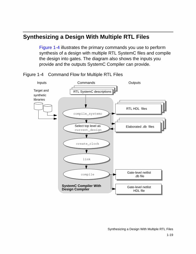
Figure 1-4 illustrates the primary commands you use to performsynthesis of a design with multiple RTL SystemC files and compilethe design into gates. The diagram also shows the inputs youprovide and the outputs SystemC Compiler can provide.
Figure 1-4 Command Flow for Multiple RTL Files
compile_systemc
RTL SystemC descriptions
Gate-level netlistcompile
Target and
librariessynthetic
SystemC Compiler WithDesign Compiler
OutputsCommandsInputs
Gate-level netlist
.db file
HDL file
link
create_clock
current_design
RTL HDL files
Elaborated .db filesSelect top level as

1-20
Chapter 1: Using SystemC Compiler for RTL Synthesis
Analyzing and Elaborating Multiple RTL Files
If your design is hierarchical and has multiple RTL files, use thecompile_systemc command to elaborate each file separately, andthen use the link command to link the internal databases beforecompiling the design to gates.
To create internal database files of your separate SystemC RTL filesfor synthesis,
• Analyze and elaborate each file in your design, using thefollowing command:
dc_shell> compile_systemc -rtl -format dbmodule1_name.cc
dc_shell> compile_systemc -rtl -format dbmodule2_name.cc
dc_shell> compile_systemc -rtl -format dbtop_module_name.cc
The compile_systemc command with the -rtl -format dboptions creates a separate internal database for each file.
If you want to compile your entire design to gates, the currentdesign must be the top-level RTL module that instantiates allother RTL modules. To ensure that the current design inSystemC Compiler memory is the top-level RTL module, executethe compile_systemc command with the file containing the topRTL module last. Or you can use the current_designcommand to make the top-level module the current design. Forexample, to change the current design to my_design_abc, enter
dc_shell> current_design my_design_abc
1-21
Synthesizing a Design With Multiple RTL Files
Setting the Clock Period
Use the create_clock command to set the clock period if yourdesign contains a clock port. If your design does not have a clockport, you can skip this command. Enter
dc_shell> create_clock -name clk -period 10
The clock period uses the same unit that is defined in the targettechnology library.
You can set other optimization and design constraints beforeperforming logic synthesis with the compile command. Forinformation about optimization and design constraints for logicsynthesis, see the Design Compiler documentation.
Linking the .db Files
After analyzing and elaborating the modules in your design andbefore compiling the design to gates, use the link command toconnect all the library components and subdesigns that your designreferences. Enter
dc_shell> link
The link command removes existing links to all library componentsand subdesigns before it starts the linking process. If you do notenter the link command to manually link the design references, thecompile command performs linking but does not remove existinglinks.

1-22
Chapter 1: Using SystemC Compiler for RTL Synthesis
Compiling and Writing the Gate-Level Netlist
Use the compile command to create the gate-level netlist of thehierarchical RTL design. This command performs logic synthesisand optimization of the current design.
dc_shell> compile -map_effort low | medium | high
Use the following command to write the gate-level netlist in .dbformat:
dc_shell> write -hierarchy -output top_module_netlist.db
Synthesizing a Design With Integrated Behavioral andRTL Modules
To perform synthesis of a design with integrated RTL and behavioralmodules, synthesize the RTL and behavioral modules to gatesbefore linking the integrated design, using the following steps:
1. Create the gate-level internal databases of your SystemC RTLmodules, as described in “Synthesizing a Design With MultipleRTL Files” on page 1-19.
2. Create the gate-level internal databases of your SystemCbehavioral modules, as described in the CoCentric SystemCCompiler Behavioral User and Modeling Guide.
If your design has more than one behavioral module, instantiatethe multiple behavioral modules in an RTL module.

1-23
Passing Parameters to a Module
3. Analyze and elaborate the top-level RTL module that combinesthe RTL and behavioral modules. Enter
dc_shell> compile_systemc -rtl -rtl_format db all_top.h
4. Use the read command to read in the RTL and behavioralmodules (.db files) that you previously compiled to gates, if theRTL and behavioral databases are not already in memory. Enter
dc_shell> read rtl_gates.dbdc_shell> read behavioral_gates.db
5. Use the link command to link the RTL, behavioral, and library.db into a single design.
dc_shell> link
6. Compile the integrated hierarchical RTL and behavioral design togates and write the gate-level netlist, as described in “Compilingand Writing the Gate-Level Netlist” on page 1-22.
Elaborating a mixed RTL-behavioral module is described in theCoCentric SystemC Compiler Behavioral User and Modeling Guide.
Passing Parameters to a Module
When you have an RTL module with one or more parameters, youcan pass the parameter values from the command line with thecompile_systemc command -param option. If the filemodule_top.cc, for example, has the following parameterizedmodule definitions
// a, b, and c are parametersM1 (const sc_module_name &name_, int a, int b, int c);
// d is a parameterM2 (const sc_module_name &name_, int d);

1-24
Chapter 1: Using SystemC Compiler for RTL Synthesis
You can pass parameter values by position to module_top.cc byentering
dc_shell> compile_systemc -rtl -param "M1 (5, 6, 7);M2 (8);" module_top.cc
This creates M1 with a = 5, b = 6, and c = 7 and M2 with d = 8.
Do not enter the module name, because it is not used for synthesis.
For more information about creating parameterized modules andsetting default parameter values, see “Defining a Constructor Withthe SC_HAS_PROCESS Macro” on page 2-18.
Limitations for Passing Parameters
When you pass module parameters with the -param option, eachparameter value must be a constant.
Names of Parameterized Modules
SystemC Compiler creates a unique module for each distinct moduleparameterization, and the parameter values are propagated into themodule. It appends the parameter values to the module name duringelaboration to create a unique module name. For example,
dc_shell> compile_systemc -rtl -param "M1 (5, 6, 7);M2 (8);" module_top.cc
This command creates the following module names:
M1_5_6_7M2_8

1-25
Passing Parameters to a Module
When you also use the -format verilog option, the followingVerilog file names are created:
M1_5_6_7.vM2_8.v
If the module contains a loop that creates more than one instance ofa module, SystemC Compiler appends the loop iteration count to themodule instance name to create a unique name.
For a particular situation, you can direct SystemC Compiler not torename the modules with the compile_systemc command-dont_rename option. For example,
dc_shell> compile_systemc -rtl -param "M1 (5, 6, 7);M2 (8);"-dont_rename "M1, M2"
module_top.cc
This command creates the following module names withoutappending the parameter values to the module name:
M1 M2
If you use the -format verilog option, the Verilog file namescreated are the following:
M1.vM2.v
1-26
Chapter 1: Using SystemC Compiler for RTL Synthesis
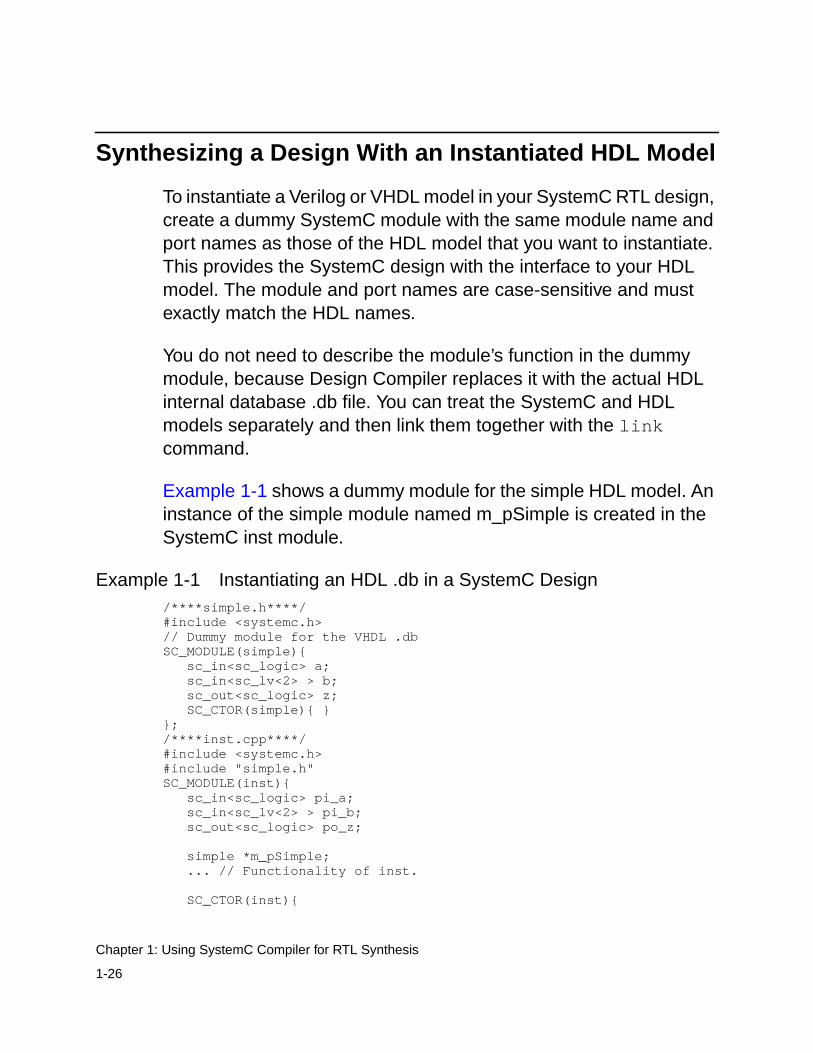
Synthesizing a Design With an Instantiated HDL Model
To instantiate a Verilog or VHDL model in your SystemC RTL design,create a dummy SystemC module with the same module name andport names as those of the HDL model that you want to instantiate.This provides the SystemC design with the interface to your HDLmodel. The module and port names are case-sensitive and mustexactly match the HDL names.
You do not need to describe the module’s function in the dummymodule, because Design Compiler replaces it with the actual HDLinternal database .db file. You can treat the SystemC and HDLmodels separately and then link them together with the linkcommand.
Example 1-1 shows a dummy module for the simple HDL model. Aninstance of the simple module named m_pSimple is created in theSystemC inst module.
Example 1-1 Instantiating an HDL .db in a SystemC Design/****simple.h****/#include <systemc.h>// Dummy module for the VHDL .dbSC_MODULE(simple){ sc_in<sc_logic> a; sc_in<sc_lv<2> > b; sc_out<sc_logic> z; SC_CTOR(simple){ }};/****inst.cpp****/#include <systemc.h>#include "simple.h"SC_MODULE(inst){ sc_in<sc_logic> pi_a; sc_in<sc_lv<2> > pi_b; sc_out<sc_logic> po_z;
simple *m_pSimple; ... // Functionality of inst.
SC_CTOR(inst){

1-27
Synthesizing a Design With an Instantiated HDL Model
m_pSimple = new simple("simple_systemc_wrapper"); m_pSimple->a(pi_a); m_pSimple->b(pi_b); m_pSimple->z(po_z); }};
You need to use the analyze, elaborate, and compilecommands with the HDL model before you use thecompile_systemc command with the SystemC design. Then usethe link command to link the internal databases before compilingthe design to gates.
To create internal database files of your separate HDL and SystemCRTL models and synthesize the design to gates, enter
/* Elaborate the HDL design into memory */dc_shell> analyze -format [vhdl simple.vhd | verilog simple.v]dc_shell> elaborate simpledc_shell> compile/* Elaborate the SystemC design into memory */dc_shell> compile_systemc -rtl inst.rtl.cppdc_shell> current_design = inst/* Link the SystemC and HDL designs */dc_shell> linkdc_shell> compile
Depending on your design, you can compile the HDL and SystemCmodules separately before linking them.
You can set other optimization and design constraints beforeperforming logic synthesis with the compile command. Forinformation about optimization and design constraints for logicsynthesis, see the Design Compiler documentation.
1-28
Chapter 1: Using SystemC Compiler for RTL Synthesis
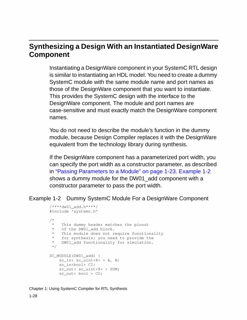
Synthesizing a Design With an Instantiated DesignWareComponent
Instantiating a DesignWare component in your SystemC RTL designis similar to instantiating an HDL model. You need to create a dummySystemC module with the same module name and port names asthose of the DesignWare component that you want to instantiate.This provides the SystemC design with the interface to theDesignWare component. The module and port names arecase-sensitive and must exactly match the DesignWare componentnames.
You do not need to describe the module’s function in the dummymodule, because Design Compiler replaces it with the DesignWareequivalent from the technology library during synthesis.
If the DesignWare component has a parameterized port width, youcan specify the port width as a constructor parameter, as describedin “Passing Parameters to a Module” on page 1-23. Example 1-2shows a dummy module for the DW01_add component with aconstructor parameter to pass the port width.
Example 1-2 Dummy SystemC Module For a DesignWare Component/****dw01_add.h****/#include "systemc.h"
/* * This dummy header matches the pinout * of the DW01_add block. * This module does not require functionality * for synthesis; you need to provide the * DW01_add functionality for simulation. */
SC_MODULE(DW01_add) { sc_in< sc_uint<8> > A, B; sc_in<bool> CI; sc_out< sc_uint<8> > SUM; sc_out< bool > CO;
1-29
Synthesizing a Design With an Instantiated DesignWare Component
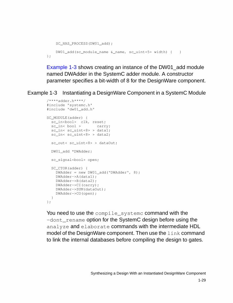
SC_HAS_PROCESS(DW01_add);
DW01_add(sc_module_name &_name, sc_uint<5> width) { }};
Example 1-3 shows creating an instance of the DW01_add modulenamed DWAdder in the SystemC adder module. A constructorparameter specifies a bit-width of 8 for the DesignWare component.
Example 1-3 Instantiating a DesignWare Component in a SystemC Module/****adder.h****/#include "systemc.h"#include "dw01_add.h"
SC_MODULE(adder) { sc_in<bool> clk, reset; sc_in< bool > carry; sc_in< sc_uint<8> > data1; sc_in< sc_uint<8> > data2;
sc_out< sc_uint<8> > dataOut;
DW01_add *DWAdder;
sc_signal<bool> open;
SC_CTOR(adder) { DWAdder = new DW01_add("DWAdder", 8); DWAdder->A(data1); DWAdder->B(data2); DWAdder->CI(carry); DWAdder->SUM(dataOut); DWAdder->CO(open); }};
You need to use the compile_systemc command with the-dont_rename option for the SystemC design before using theanalyze and elaborate commands with the intermediate HDLmodel of the DesignWare component. Then use the link commandto link the internal databases before compiling the design to gates.

1-30
Chapter 1: Using SystemC Compiler for RTL Synthesis
To create internal databases of the SystemC RTL model andsynthesize the design to gates,
/* Elaborate the SystemC design into memory * and create an intermediate HDL file */dc_shell> compile_systemc -rtl -format [verilog | vhdl]
-dont_rename "DW01_add" adder.h/* Elaborate the HDL design into memory */dc_shell> analyze -format [vhdl simple.vhd | verilog simple.v]dc_shell> elaborate simple/* Link the SystemC and HDL designs */dc_shell> linkdc_shell> compile
Implementing functions with DesignWare components is describedin “Specifying Preserved Functions and Implementing DesignWareComponents” on page 2-43.

2-1
2Creating SystemC Modules for Synthesis 2
This chapter explains the SystemC and C/C++ language elementsthat are important for RTL synthesis with SystemC Compiler. Itcontains the following sections:
• Defining Modules and Processes
• Creating a Module
• Creating a Module With a Single SC_METHOD Process
• Creating a Module With Multiple SC_METHOD Processes
• Creating a Hierarchical RTL Module
• Creating an Integrated RTL and Behavioral Module
• Specifying Preserved Functions and Implementing DesignWareComponents

2-2
Chapter 2: Creating SystemC Modules for Synthesis
Defining Modules and Processes
This modeling guide explains how to develop SystemC RTL modulesfor synthesis with SystemC Compiler. It assumes that you areknowledgeable about the C/C++ language and the SystemC ClassLibrary available from the Open SystemC Community Web site athttp://www.systemc.org.
Modules
The basic building block in SystemC is the module. A SystemCmodule is a container in which processes and other modules areinstantiated. For synthesis with SystemC Compiler, modules areeither RTL or behavioral. A typical module can have
• Single or multiple RTL processes to specify combinational orsequential logic
• Single or multiple behavioral processes
• Multiple instantiated modules to specify hierarchy
• One or more member functions that are called from within aninstantiated process
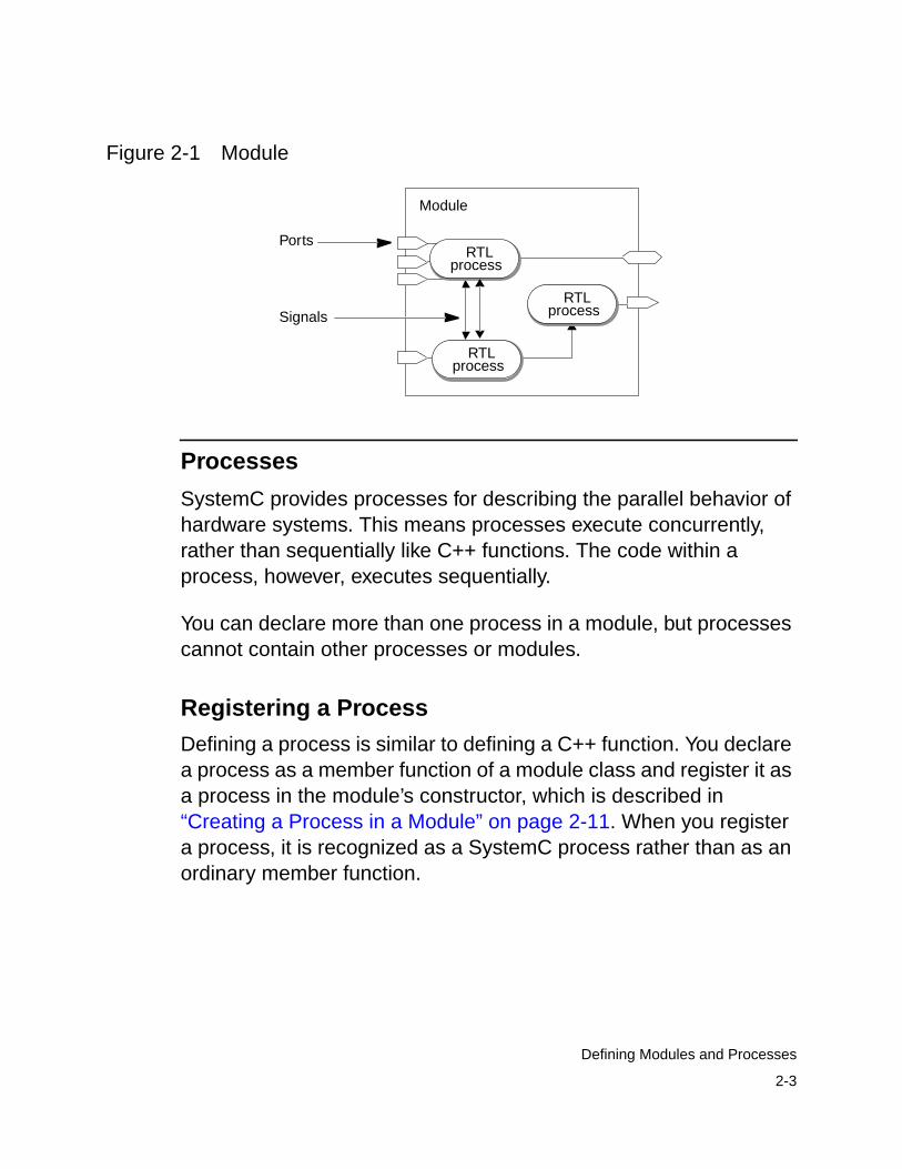
Figure 2-1 illustrates a module with several RTL processes. Theprocesses within a module are concurrent, and they executewhenever one of their sensitive inputs changes.
2-3
Defining Modules and Processes
Figure 2-1 Module
Processes
SystemC provides processes for describing the parallel behavior ofhardware systems. This means processes execute concurrently,rather than sequentially like C++ functions. The code within aprocess, however, executes sequentially.
You can declare more than one process in a module, but processescannot contain other processes or modules.
Registering a Process
Defining a process is similar to defining a C++ function. You declarea process as a member function of a module class and register it asa process in the module’s constructor, which is described in“Creating a Process in a Module” on page 2-11. When you registera process, it is recognized as a SystemC process rather than as anordinary member function.
Module
RTLprocess
RTLprocess
RTLprocess
Ports
Signals
2-4
Chapter 2: Creating SystemC Modules for Synthesis
You can register multiple processes, but it is an error to register morethan one instance of the same process. To create multiple instancesof the same process, enclose the process in a module andinstantiate the module multiple times.
Triggering Execution of a Process
You define a sensitivity list that identifies which input ports andsignals trigger the execution of the code within a process. You candefine level-sensitive inputs to specify combinational logic oredge-sensitive inputs to specify sequential logic, which is describedin “Defining the Sensitivity List” on page 2-12.
Reading and Writing in a Process
A process can read from and write to ports, signals, and internalvariables, as described in “Reading and Writing Ports and Signals”on page 2-28.
Processes use signals to communicate with each other. Oneprocess can cause another process to execute by assigning a newvalue to a signal that connects them. Do not use data variables forcommunication between processes, because the processes executein random order and it can cause nondeterminism (orderdependencies) during simulation.
Types of Processes
SystemC provides three process types—SC_METHOD,SC_CTHREAD, and SC_THREAD—that execute whenever theirsensitive inputs change. A process has a sensitivity list that identifieswhich inputs trigger the code within the process to execute when thevalue on one of its sensitive inputs changes.
2-5
Defining Modules and Processes
For simulation and testbenches, you can use any of the processtypes.
SC_METHOD Process. The SC_METHOD process is used todescribe a hierarchical design or RTL hardware. It is level sensitive,meaning it is sensitive to changes in the signal values, or it is edgesensitive, meaning it is sensitive to particular transitions (edges) ofthe signal, and it executes when one of its sensitive inputs changes.
SC_CTHREAD Process. The SC_CTHREAD clocked threadprocess is sensitive to one edge of one clock. Use a clocked threadprocess to describe functionality for behavioral synthesis withSystemC Compiler.
The SC_CTHREAD process models the behavior of a sequentiallogic circuit with nonregistered inputs and registered outputs. Aregistered output comes directly from a register (flip-flop) in thesynthesized circuit.
For information about creating behavioral processes, see theCoCentric SystemC Compiler Behavioral User and Modeling Guide.
Thread Process. The SC_THREAD process is not used forsynthesis. For more information about the SC_THREAD process,see the SystemC documentation at the Open SystemC CommunityWeb site http://www.systemc.org.
2-6
Chapter 2: Creating SystemC Modules for Synthesis
Creating a Module
As a recommended coding practice, describe a module by using aseparate header file (module_name.h) and an implementation file(module_name.cpp or module_name.cc).
Module Header File
Each module header file contains
• Port declarations
• Internal signal variable declarations
• Internal data variable declarations
• Process declarations
• Member function declarations
• A module constructor
Module Syntax
Declare a module by using the syntax shown in bold in the followingexample:
#include "systemc.h"SC_MODULE (module_name) {
//Module port declarations//Signal variable declarations//Data variable declarations//Member function declarations//Method process declarations
//Module constructorSC_CTOR (module_name) {
//Register processes//Declare sensitivity list
}
2-7
Creating a Module
};
SC_MODULE and SC_CTOR are C++ macros defined in theSystemC Class library.
Module Ports
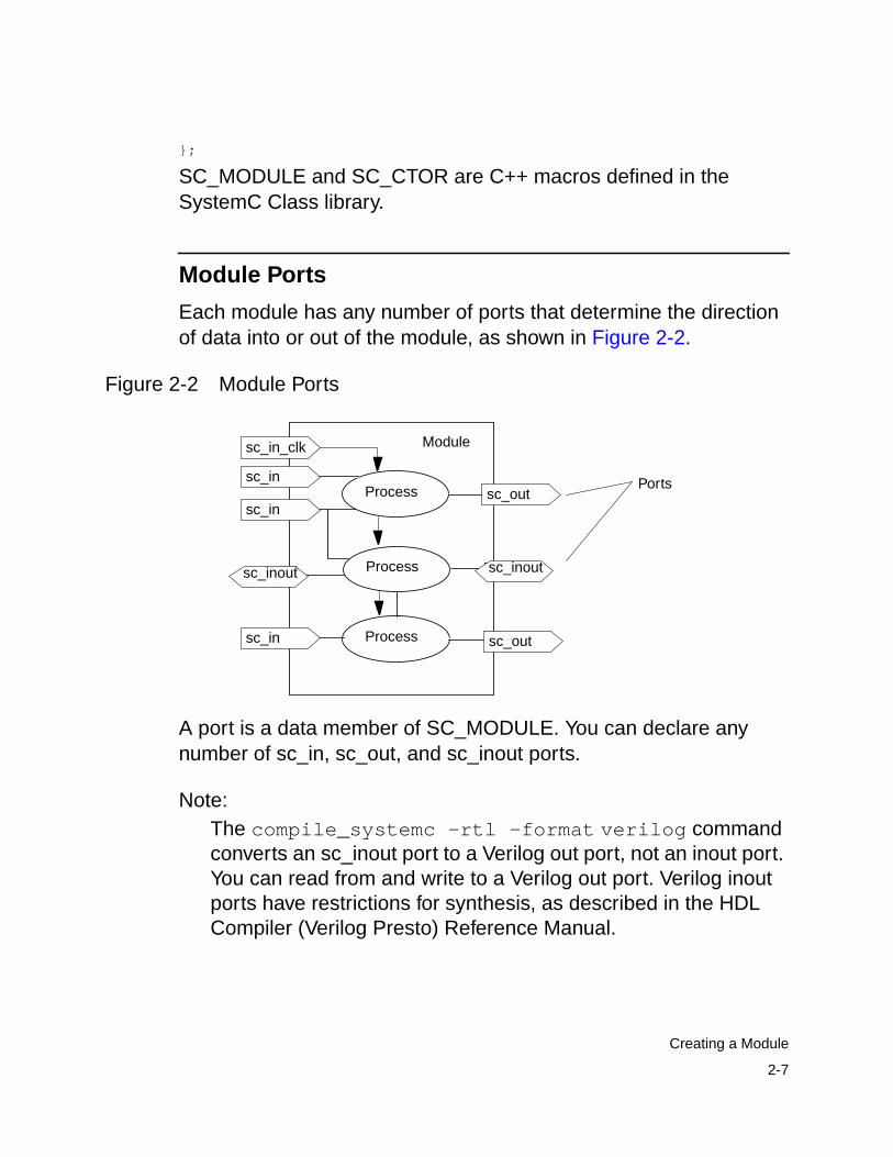
Each module has any number of ports that determine the directionof data into or out of the module, as shown in Figure 2-2.
Figure 2-2 Module Ports
A port is a data member of SC_MODULE. You can declare anynumber of sc_in, sc_out, and sc_inout ports.
Note:The compile_systemc -rtl -format verilog commandconverts an sc_inout port to a Verilog out port, not an inout port.You can read from and write to a Verilog out port. Verilog inoutports have restrictions for synthesis, as described in the HDLCompiler (Verilog Presto) Reference Manual.
Process
Process
Process
Module
Portssc_in
sc_in_clk
sc_outsc_in
sc_in sc_out
sc_inout sc_inout

2-8
Chapter 2: Creating SystemC Modules for Synthesis
For VHDL, the compile_systemc -rtl -format vhdlcommand treats an sc_inout port as a VHDL inout port. It treatsan sc_out port as an out port and a signal or an out port,depending on the situation.
Port Syntax
Declare ports by using the syntax shown in bold in the followingexample:
SC_MODULE (module_name) {//Module port declarationssc_in<port_data_type> port_name;sc_out<port_data_type> port_name;sc_inout<port_data_type> port_name;sc_in<port_data_type> port_name;
//Module constructorSC_CTOR (module_name) {
//Register processes//Declare sensitivity list
}};
Port Data Types
Ports connect to signals and have a data type associated with them.For synthesis, declare each port as one of the synthesizable datatypes described in “Converting to a Synthesizable Subset” onpage 3-2.
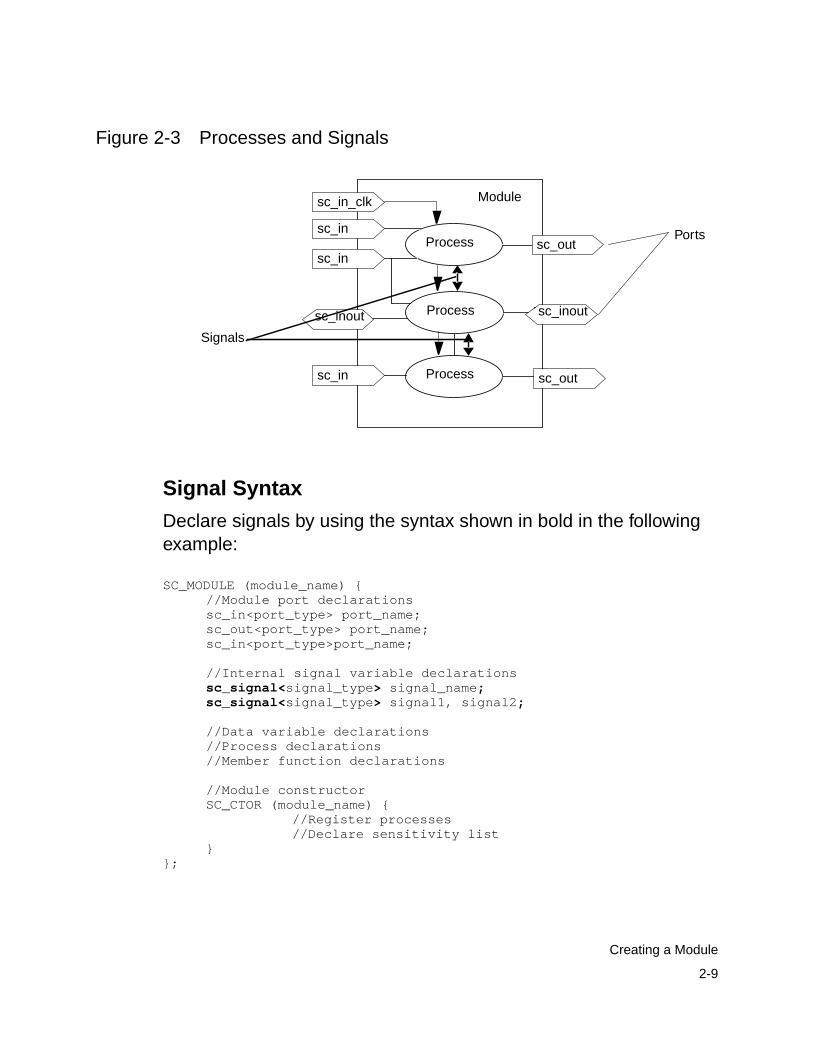
Signals
Modules use ports to communicate with other modules. Inhierarchical modules, use signals to communicate between theinstantiated modules. Use internal signals for peer-to-peercommunication between processes within the same module, asshown in Figure 2-3.
2-9
Creating a Module
Figure 2-3 Processes and Signals
Signal Syntax
Declare signals by using the syntax shown in bold in the followingexample:
SC_MODULE (module_name) {//Module port declarationssc_in<port_type> port_name;sc_out<port_type> port_name;sc_in<port_type>port_name;
//Internal signal variable declarationssc_signal<signal_type> signal_name;sc_signal<signal_type> signal1, signal2;
//Data variable declarations//Process declarations//Member function declarations
//Module constructorSC_CTOR (module_name) {
//Register processes//Declare sensitivity list
}};
Process
Process
Process
Module
Portssc_in
sc_in_clk
sc_outsc_in
sc_in sc_out
sc_inout sc_inout
Signals

2-10
Chapter 2: Creating SystemC Modules for Synthesis
Signal Data Types
A signal’s bit-width is determined by its corresponding data type.Specify the data type as any of the synthesizable SystemC or C++data types listed in “Converting to a Synthesizable Subset” onpage 3-2. Signals and the ports they connect must have the samedata types.
Data Member Variables
Inside a module, you can define data member variables of anysynthesizable SystemC or C++ type. These variables can be usedfor internal storage in the module. Recommendations about usingdata member variables for synthesis are provided in “Data Membersof a Module” on page 3-18. Declare internal data variables by usingthe syntax shown in bold in the following example:
SC_MODULE (module_name) {//Module port declarationssc_in<port_type> port_name;sc_out<port_type> port_name;sc_in port_name;
//Internal signal variable declarationssc_signal<signal_type> signal_name;
//Data member variable declarationsint count_val; //Internal countersc_int<8> mem[1024]; //Array of sc_int
//Process declarations//Member function declaration
//Module constructorSC_CTOR (module_name) {
//Register processes//Declare sensitivity list
}};
2-11
Creating a Module
Note:Do not use data variables for peer-to-peer communication in amodule. This can cause pre-synthesis and post-synthesissimulation mismatches and nondeterminism (order dependency)in your design.
Assigning to Data Members in the Constructor
You can make assignments to data members from within theconstructor. These assignments are treated as constants forsynthesis. You cannot reassign the data members within anyprocess in the module.
Creating a Process in a Module
You declare a process as a member function of a module class andregister it as a process in the module’s constructor. You must declarea process with a return type of void and no arguments, as shown inbold in Example 2-1.
To register a function as an SC_METHOD process, use theSC_METHOD macro that is defined in the SystemC class library.The SC_METHOD macro takes one argument, the name of theprocess.

2-12
Chapter 2: Creating SystemC Modules for Synthesis
Example 2-1 Creating a Method Process in a ModuleSC_MODULE(my_module){
// Portssc_in<int> a;sc_in<bool> b;sc_out<int> x;sc_out<int> y;// Internal signalssc_signal<bool>c;sc_signal<int> d;// process declarationvoid my_method_proc();// module constructorSC_CTOR(my_module) {
// register processSC_METHOD(my_method_proc);// Define the sensitivity list
}};
Defining the Sensitivity List
An SC_METHOD process reacts to a set of signals called itssensitivity list. You can use the sensitive(), sensitive_pos(), orsensitive_neg() functions or the sensitive, sensitive_pos, orsensitive_neg streams in the sensitivity declaration list.
Defining a Level-Sensitive Process
For combinational logic, define a sensitivity list that includes all inputports, inout ports, and signals used as inputs to the process. Use thesensitive() method to define the level-sensitive inputs. Example 2-2shows in bold a stream-type declaration and a function-typedeclaration. Specify any number of sensitive inputs for thestream-type declaration, and specify only one sensitive input for thefunction-type declaration. You can call the sensitive function multipletimes with different inputs.
2-13
Creating a Module
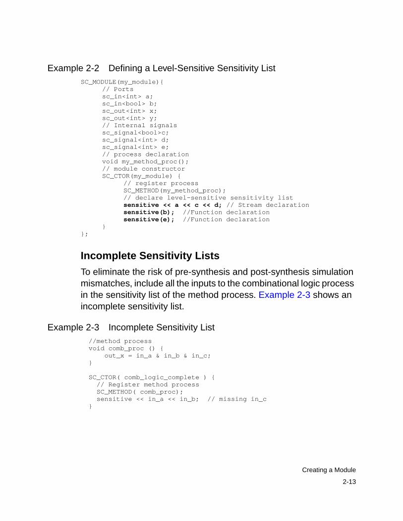
Example 2-2 Defining a Level-Sensitive Sensitivity ListSC_MODULE(my_module){
// Portssc_in<int> a;sc_in<bool> b;sc_out<int> x;sc_out<int> y;// Internal signalssc_signal<bool>c;sc_signal<int> d;sc_signal<int> e;// process declarationvoid my_method_proc();// module constructorSC_CTOR(my_module) {
// register processSC_METHOD(my_method_proc);// declare level-sensitive sensitivity listsensitive << a << c << d; // Stream declarationsensitive(b); //Function declarationsensitive(e); //Function declaration
}};
Incomplete Sensitivity Lists
To eliminate the risk of pre-synthesis and post-synthesis simulationmismatches, include all the inputs to the combinational logic processin the sensitivity list of the method process. Example 2-3 shows anincomplete sensitivity list.
Example 2-3 Incomplete Sensitivity List //method process void comb_proc () { out_x = in_a & in_b & in_c; }
SC_CTOR( comb_logic_complete ) { // Register method process SC_METHOD( comb_proc); sensitive << in_a << in_b; // missing in_c }

2-14
Chapter 2: Creating SystemC Modules for Synthesis
SystemC Compiler issues a warning if your sensitivity list isincomplete, but it proceeds to build a 3-input AND gate for thedescription in Example 2-3. When you simulate this description,however, out_x is not recalculated when in_c changes, because in_cis not in the sensitivity list. The simulated behavior, therefore, is notthat of a 3-input AND gate.
Defining an Edge-Sensitive Process
For sequential logic, define a sensitivity list of the input ports andsignals that trigger the process. Use the sensitive_pos(), thesensitive_neg(), or both the sensitive_pos() and sensitive_neg()methods to define the edge-sensitive inputs that trigger the process.Declare ports and the edge-sensitive inputs as type sc_in<bool>.
For edge-sensitive inputs, SystemC Compiler tests for the rising orfalling edge of the signal. It infers flip-flops for variables that areassigned values in the process.
Define the sensitivity list by using either the function or the streamsyntax. Example 2-4 shows in bold an example of a stream-typedeclaration for two inputs and a function-type declaration for theclock input.

2-15
Creating a Module
Example 2-4 Defining an Edge-Sensitive Sensitivity ListSC_MODULE(my_module){
// Portssc_in<int> a;sc_in<bool> b;sc_in<bool> clock;sc_out<int> x;sc_out<int> y;sc_in<bool> reset, set;// Internal signalssc_signal<bool>c;sc_signal<int> d;// process declarationvoid my_method_proc();// module constructorSC_CTOR(my_module) {
// register processSC_METHOD(my_method_proc);// declare sensitivity listsensitive_pos (clock); //Function delarationsensitive_neg << reset << set; // Stream declaration
}};
Limitations for Sensitivity Lists
When you define a sensitivity list, adhere to the following limitations:
• You cannot specify both edge-sensitive and level-sensitive inputsin the same process for synthesis.
• You cannot declare an sc_logic type for the clock or otheredge-sensitive inputs. You can declare only an sc_in<bool> datatype.
Member Functions
You can declare member functions in a module that are notprocesses. This type of member function is not registered as aprocess in the module’s constructor. It can be called from a process.Member functions can contain any synthesizable C++ or SystemCstatement allowed in an SC_METHOD process.
2-16
Chapter 2: Creating SystemC Modules for Synthesis
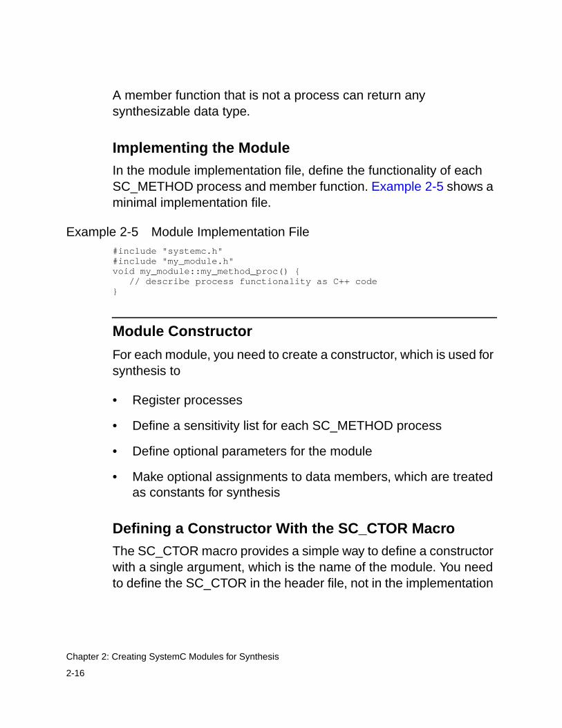
A member function that is not a process can return anysynthesizable data type.
Implementing the Module
In the module implementation file, define the functionality of eachSC_METHOD process and member function. Example 2-5 shows aminimal implementation file.
Example 2-5 Module Implementation File#include "systemc.h"#include "my_module.h"void my_module::my_method_proc() { // describe process functionality as C++ code}
Module Constructor
For each module, you need to create a constructor, which is used forsynthesis to
• Register processes
• Define a sensitivity list for each SC_METHOD process
• Define optional parameters for the module
• Make optional assignments to data members, which are treatedas constants for synthesis
Defining a Constructor With the SC_CTOR Macro
The SC_CTOR macro provides a simple way to define a constructorwith a single argument, which is the name of the module. You needto define the SC_CTOR in the header file, not in the implementation

2-17
Creating a Module
file. Within the constructor’s body, you register each process for themodule. For synthesis, other statements are not allowed in theSC_CTOR constructor.
Example 2-6 shows in bold a constructor defined with an SC_CTORmacro.
Example 2-6 Module Constructor// my_module.h header fileSC_MODULE (my_module) {
// Declare portssc_in<bool> reset;sc_in<sc_int<8> > data_in;sc_in_clk clk;sc_out<sc_int<16> > real_out;sc_out<sc_int<16> > imaginary_out;
// Declare internal variables and signals
// Declare processes in the modulevoid my_method_proc();
// ConstructorSC_CTOR (my_module){
// Register processes...// Define the sensitivity lists...
}};
Registering a Process
To register a function as a process, use the SC_METHOD macro foran RTL process and the SC_CTHREAD macro for a behavioralprocess. These macros are defined in the SystemC library.
The SC_METHOD macro takes a single argument, the name of aprocess to register. In addition, you need to define one or moresensitivity lists for each process.

2-18
Chapter 2: Creating SystemC Modules for Synthesis
Example 2-7 shows in bold a module with an SC_CTOR constructorthat registers an SC_METHOD process and defines two sensitivitylists for the process.
Example 2-7 Registering a Process and Defining a SensitivityList
SC_MODULE(my_module){// Portssc_in<int> a;sc_in<bool> b;sc_in<bool> clock;sc_out<int> x;sc_out<int> y;sc_in<bool> reset, set;// Internal signalssc_signal<bool>c;sc_signal<int> d;// process declarationvoid my_method_proc();// module constructorSC_CTOR(my_module) {
// register processSC_METHOD(my_method_proc);// declare sensitivity listssensitive_pos (clock); //Function delarationsensitive_neg << reset << set; // Stream declaration
}};
Defining a Constructor With the SC_HAS_PROCESSMacro
You can use the SC_HAS_PROCESS macro, introduced inSystemC 2.0, instead of the SC_CTOR macro to define aconstructor with standard C++ syntax and any number ofparameters. You might want to define a constructor with multipleparameters, for example, to specify values when instantiating themodule, to pass a unique identification to a block, or to change thenumber of iterations performed for a certain algorithm.

2-19
Creating a Module
Using the SC_HAS_PROCESS macro, you can define theconstructor in the header file or in the implementation file. Moving theconstructor definition into the implementation lets you hide some ofthe module’s functionality when providing an IP to an end user.
Defining the Constructor Parameters. When you use theSC_HAS_PROCESSES macro to define a constructor, do not definea return type for the constructor. Define the first argument of theconstructor as an sc_module_name or a char * type. You need todefine the module name parameter even though it is not used forsynthesis.
You can then define any number of integral parameter arguments. Aparameter can have a default value, which you assign in theconstructor. The module receives parameter values when youinstantiate it or pass values with the compile_systemc command.Inside the module, the parameters are constant values.
Example 2-8 shows a constructor with parameters. The related codeis highlighted in bold.
Example 2-8 Module Constructor With Parameters/****parm2.h****/#include "systemc.h"
SC_MODULE(parm2) { sc_in_clk clk; sc_in<bool> reset; sc_in< sc_uint<8> > data1, data2; sc_out< sc_uint<16> > data_out;
SC_HAS_PROCESS(parm2);
void mult1();
bool const_var1; sc_uint<9> const_var2; // Constructor with parameters without default valuesparm2( const sc_module_name& name_,
bool const1, sc_uint<9> const2 );

2-20
Chapter 2: Creating SystemC Modules for Synthesis
};/****parm2.cc****/#include "parm2.h"parm2::parm2(const sc_module_name& name_,
bool const1, sc_uint<9> const2){const_var1 = const1;const_var2 = const2;SC_METHOD(mult1);sensitive_pos << clk << reset;
}void parm2::mult1() { if (reset.read() == 1) { data_out.write(4); } else { sc_uint<16> tmp1 = (data1.read() * data2.read()); sc_uint<10> tmp2 = const_var1 + const_var2; sc_uint<16> tmp3 = tmp1 + tmp2; data_out.write(tmp3); }}
Instantiating a Module With Parameters. When you instantiate amodule that has parameters, pass the constructor parameters byposition. The passed parameters must be constant values at compiletime. Example 2-9 shows instantiation of the parm1 module in theuse_parms module. The related code is highlighted in bold.
Example 2-9 Instantiating a Module With Parameters/****use_parms.h****/#include "systemc.h"#include "parm2.h"SC_MODULE(use_parms){
parm2 *parm;parm = new parm2("my_name", 1, 6);
...};
You can also pass parameter values to a module from the commandline with the compile_systemc command -param option, asdescribed in “Passing Parameters to a Module” on page 1-23.

2-21
Creating a Module
Setting and Using Default Parameter Values. It is recommendedthat you initialize all parameters by assigning default values.
Example 2-10 shows in bold a constructor with two parameters thatare assigned default values of 0 and 7. The parameter default valuesare used unless you instantiate the module with parameter values oryou pass parameter values with the compile_systemc command-param option.
Example 2-10 Module Constructor With Parameter DefaultValues
/****parm2a.h****/#include "systemc.h"
SC_MODULE(parm2a) { sc_in_clk clk; sc_in<bool> reset; sc_in< sc_uint<8> > data1, data2; sc_out< sc_uint<16> > data_out;SC_HAS_PROCESS(parm2a);
void mult1(); bool const_var1; sc_uint<9> const_var2;
// Parameters with default valuesparm2a( const sc_module_name& name_,
bool const1 = 0, sc_uint<9> const2 = 7 );};/****parm2a.cc****/#include "parm2a.h"
parm2a::parm2a(const sc_module_name& name_,bool const1, sc_uint<9> const2){
const_var1 = const1;const_var2 = const2;
SC_METHOD(mult1); sensitive_pos << clk << reset;}
void parm2a::mult1() { if (reset.read() == 1) { data_out.write(4); } else { sc_uint<16> tmp1 = (data1.read() * data2.read()); sc_uint<10> tmp2 = const_var1 + const_var2; sc_uint<16> tmp3 = tmp1 + tmp2;

2-22
Chapter 2: Creating SystemC Modules for Synthesis
data_out.write(tmp3); }}
If a module defines default parameter values of 0 and 7 as inExample 2-10, when you instantiate the module without parametervalues or use the compile_systemc command without the -parmoption, the default values are used.
For example,
dc_shell> compile_systemc -rtl -format verilog parm2a.cc
This command uses the default values 0 and 7.
When you provide parameter values, it overrides the default values.For example,
dc_shell> compile_systemc -rtl -format verilog-param "parm2a(1,6);" parm2a.cc
This command uses the values 1 and 6.
You can also specify a partial parameter list. Any parameter notspecified with the -param option uses the default values. Forexample,
dc_shell> compile_systemc -rtl -format verilog-param "parm2a(1);" parm2a.cc
This command uses the values 1 and 7 because the default value ofconst2 is 7.
Parameters are passed by position, and default parameter valuesare substituted only for the missing trailing arguments. Arrange theparameter list so the parameters that are most likely to takeuser-specified values are specified first.

2-23
Creating a Module
Initializing in the Constructor. To make it easier to createsensitivity lists, assign to signals, and perform other repetitiveinitialization tasks, you can include loops in the constructor.
Use simple assignments for initialization. All for loops used in aconstructor must be unrollable. Do not use a data member as a loopcounter variable.
Creating a Sensitivity List With a Loop. Example 2-11 shows amodule that uses loops to create the sensitivity list in two processes.
Example 2-11 Loop to Define Sensitivity List/****sens_loop.h****/#include "systemc.h"
#define DESIGN sens_loop
SC_MODULE(sens_loop) { sc_in_clk clk; sc_in<bool> reset; sc_in< sc_uint<8> > data[4]; sc_out< sc_uint<16> > data_out[2];
SC_HAS_PROCESS(sens_loop);
sc_signal< sc_uint<8> > int_indata[4]; sc_signal< sc_uint<16> > int_outdata[2];
void mult_reg(); void read_inputs(); void assign_outputs();
sens_loop( const sc_module_name& name_, int const1 = 4, int const2 = 2);};/****sens_loop.cpp****/#include "sens_loop.h"
sens_loop::sens_loop( const sc_module_name& name_, int const1, int const2) {
SC_METHOD(mult_reg); sensitive_pos << clk;
SC_METHOD(read_inputs);

2-24
Chapter 2: Creating SystemC Modules for Synthesis
for(int i = 0; i < const1; i++){ /* synopsys unroll */ sensitive << data[i]; } SC_METHOD(assign_outputs); for(int i = 0; i < const2; i++) {
/* synopsys unroll */ sensitive << int_outdata[i]; }}
void sens_loop::mult_reg() { sc_uint<16> tmp1 = data[0].read() * data[1].read(); sc_uint<16> tmp2 = data[2].read() * data[3].read(); int_outdata[0] = tmp1; int_outdata[1] = tmp2;}
void sens_loop::read_inputs() { for(int i =0; i < const1; i++){
/* synopsys unroll */ int_indata[i] = data[i].read(); }}
void sens_loop::assign_outputs() { for(int i = 0; i< const2; i++){
/* synopsys unroll */ data_out[i].write(int_outdata[i].read()); }}#include "systemc.h"
#define DESIGN sens_loop
SC_MODULE(sens_loop) { sc_in_clk clk; sc_in<bool> reset; sc_in< sc_uint<8> > data[4]; sc_out< sc_uint<16> > data_out[2];
SC_HAS_PROCESS(sens_loop);
sc_signal< sc_uint<8> > int_indata[4]; sc_signal< sc_uint<16> > int_outdata[2];
void mult_reg(); void read_inputs(); void assign_outputs();
sens_loop( const sc_module_name& name_, int const1 = 4, int const2 = 2);};

2-25
Creating a Module
#include "sens_loop.h"
sens_loop::sens_loop( const sc_module_name& name_, int const1, int const2) {
SC_METHOD(mult_reg); sensitive_pos << clk;
SC_METHOD(read_inputs); for(int i = 0; i < const1; i++){ /* synopsys unroll */ sensitive << data[i]; } SC_METHOD(assign_outputs); for(int i = 0; i < const2; i++) {
/* synopsys unroll */ sensitive << int_outdata[i]; }}
void sens_loop::mult_reg() { sc_uint<16> tmp1 = data[0].read() * data[1].read(); sc_uint<16> tmp2 = data[2].read() * data[3].read(); int_outdata[0] = tmp1; int_outdata[1] = tmp2;}
void sens_loop::read_inputs() { for(int i =0; i < const1; i++){
/* synopsys unroll */ int_indata[i] = data[i].read(); }}
void sens_loop::assign_outputs() { for(int i = 0; i< const2; i++){
/* synopsys unroll */ data_out[i].write(int_outdata[i].read()); }}
Instantiating Multiple Modules With a Loop. Example 2-12defines an asynchronous reset D flip-flop. The has_loop_inst moduleinstantiates back-to-back pairs of the D flip-flop, which are typicallycalled synchronizers. The TMP signal is an intermediate node thatconnects between each flip-flop pair.

2-26
Chapter 2: Creating SystemC Modules for Synthesis
This example uses the NUM_INSTS macro to set the parameter thatdefines the number of pairs to instantiate and the width of the IN andOUT ports. This value is set to a default of 4.
Example 2-12 Instantiating Multiple Modules With a Loop/****loopinst.h****/#include "systemc.h"
// This module defines a typical asynchronous// reset D flip-flop, which is sensitive to// the positive clock edge.
SC_MODULE(dff_pos_module) { sc_in<bool>in_data; sc_out<bool> out_q; sc_in_clkclock; sc_in<bool>reset;
void dff_pos_function() { if (reset){
out_q = 0; }else{ out_q = in_data; } }
SC_CTOR(dff_pos_module) { SC_METHOD(dff_pos_function); sensitive_pos << clock << reset; }};
// This loop instantiates two-level// (back-to-back) D flip-flops, which// is often called synthronizers.// The signal TMP is an intermediate node that// connects between the two D flip-flops.
SC_MODULE(has_loop_inst) {
// By default, the number of instances and // the IN and OUT port widths are set to 4. // Specify a different number of instances // in the synthesis script or the Makefile. #ifndef NUM_INSTS #define NUM_INSTS 4 #endif
sc_in<bool> clock; sc_in<bool> reset;
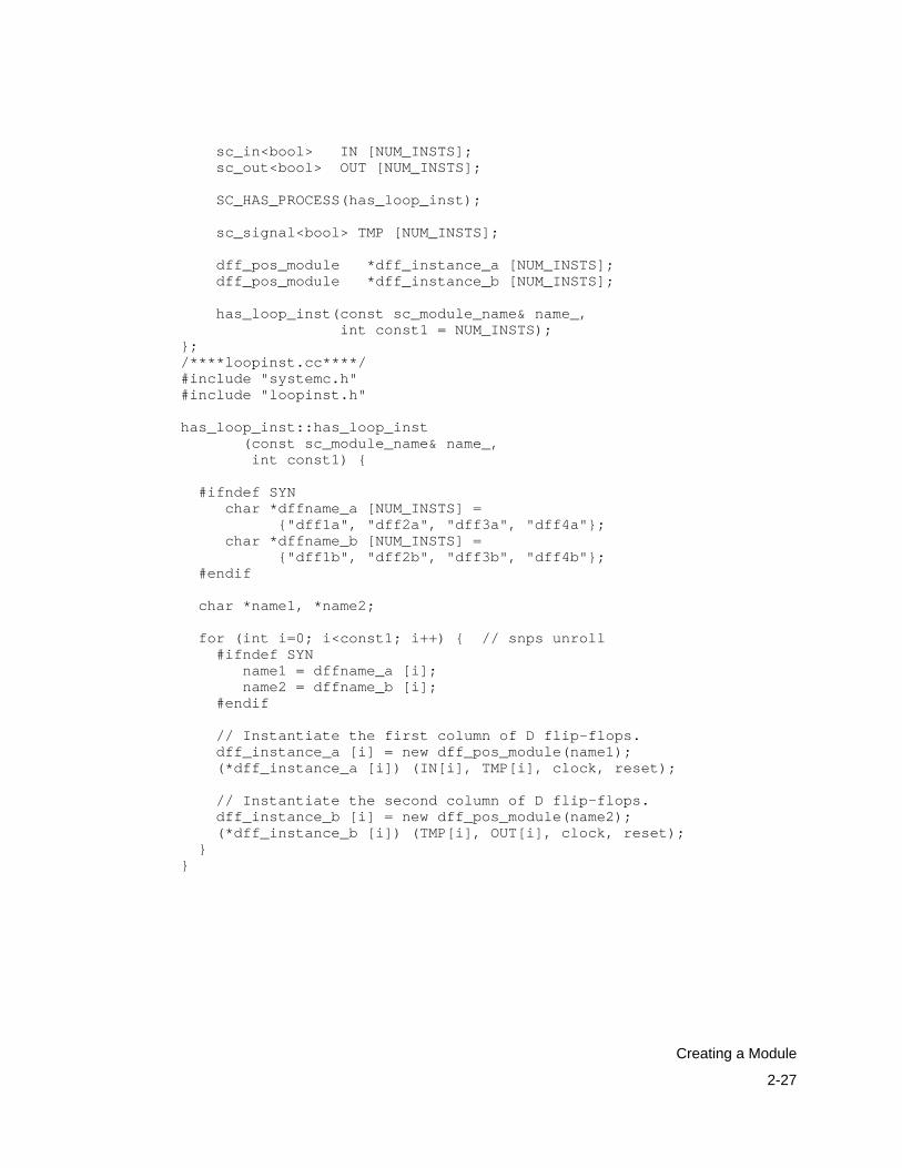
2-27
Creating a Module
sc_in<bool> IN [NUM_INSTS]; sc_out<bool> OUT [NUM_INSTS];
SC_HAS_PROCESS(has_loop_inst);
sc_signal<bool> TMP [NUM_INSTS];
dff_pos_module *dff_instance_a [NUM_INSTS]; dff_pos_module *dff_instance_b [NUM_INSTS];
has_loop_inst(const sc_module_name& name_, int const1 = NUM_INSTS);};/****loopinst.cc****/#include "systemc.h"#include "loopinst.h"
has_loop_inst::has_loop_inst (const sc_module_name& name_, int const1) {
#ifndef SYN char *dffname_a [NUM_INSTS] = {"dff1a", "dff2a", "dff3a", "dff4a"}; char *dffname_b [NUM_INSTS] = {"dff1b", "dff2b", "dff3b", "dff4b"}; #endif
char *name1, *name2;
for (int i=0; i<const1; i++) { // snps unroll #ifndef SYN name1 = dffname_a [i]; name2 = dffname_b [i]; #endif
// Instantiate the first column of D flip-flops. dff_instance_a [i] = new dff_pos_module(name1); (*dff_instance_a [i]) (IN[i], TMP[i], clock, reset);
// Instantiate the second column of D flip-flops. dff_instance_b [i] = new dff_pos_module(name2); (*dff_instance_b [i]) (TMP[i], OUT[i], clock, reset); }}

2-28
Chapter 2: Creating SystemC Modules for Synthesis
Limitation of Using Constructor Parameters. Because of C++restrictions, you cannot define a constructor parameter to
• Specify the bit-width of data types
• Change anything defined outside the constructor, such asmemory size, the number of ports, or function prototypes
SystemC Compiler has the following restrictions for using aconstructor defined with the SC_HAS_PROCESSES macro:
• A parameter cannot be a struct type.
• Use only simple data member assignment statements in theconstructor.
• Use only unrollable for loops.
Reading and Writing Ports and Signals
In the module implementation description, you can read from or writeto a port or a signal by using the read and write methods or byassignment. An sc_out port and an sc_inout port have read() andwrite() methods to allow you to read from or write to the port. Ansc_in port has only a read() method.
When you read from or write to a port or a signal, a recommendedcoding practice is to use the read() and write() methods to distinguishport and signals from variable assignments. The read() and write()methods perform any necessary data conversion. Use theassignment operator for variables. Example 2-13 shows in bold howto use the read and write methods for ports and signals, and it showsassignment operators for variables.

2-29
Creating a Module
Example 2-13 Using Assignment and read() and write() Methods// read methodaddress = into.read(); // get address// assignmenttemp1 = address; // save addressdata_tmp = memory[address]; // get data from memory// write methodoutof.write(data_tmp); // write out// assignmenttemp2 = data_tmp;// save data_tmp//...
Reading and Writing Bits of Ports and Signals
You read or write all bits of a port or signal. You cannot read or writethe individual bits, regardless of the type. To do a bit-select on a portor signal, read the value into a temporary variable and do a bit-selecton the temporary variable. Example 2-14 shows in bold how to readfrom or write bits to a temporary variable.
Example 2-14 Reading and Writing Bits of a Variable//...sc_signal <sc_int<8> > a;sc_int<8> b;bool c;b = a.read();c = b[0];
// c = a[0]; // Will not work in SystemC
Example 2-14 reads the value of signal a into temporary variable band writes bit 0 of b into variable c. You cannot read a bit from signala, because this operation is not allowed in SystemC.
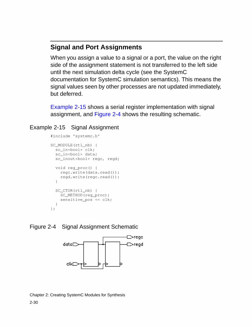
2-30
Chapter 2: Creating SystemC Modules for Synthesis
Signal and Port Assignments
When you assign a value to a signal or a port, the value on the rightside of the assignment statement is not transferred to the left sideuntil the next simulation delta cycle (see the SystemCdocumentation for SystemC simulation semantics). This means thesignal values seen by other processes are not updated immediately,but deferred.
Example 2-15 shows a serial register implementation with signalassignment, and Figure 2-4 shows the resulting schematic.
Example 2-15 Signal Assignment#include "systemc.h"
SC_MODULE(rtl_nb) { sc_in<bool> clk; sc_in<bool> data; sc_inout<bool> regc, regd;
void reg_proc() { regc.write(data.read()); regd.write(regc.read()); }
SC_CTOR(rtl_nb) { SC_METHOD(reg_proc); sensitive_pos << clk; }};
Figure 2-4 Signal Assignment Schematic

2-31
Creating a Module
Variable Assignment
When you assign a value to a variable, SystemC Compiler considersthat the value on the right side is transferred immediately to the leftside of the assignment statement.
Example 2-16 includes a variable assignment, in which theimplementation assigns the value of data to rega and regb, as theresulting schematic in Figure 2-5 indicates.
Note:This example is only an illustration of variable assignment. Youcan write the same behavior more efficiently by removing therega_v and regb_v variables and writing the ports directly.
Example 2-16 Variable Assignment#include "systemc.h"
SC_MODULE(rtl_b) { sc_in<bool> clk; sc_in<bool> data; sc_out<bool> rega, regb;
bool rega_v, regb_v;
void reg_proc() { rega_v = data.read(); regb_v = rega_v; rega.write(rega_v); regb.write(regb_v); }
SC_CTOR(rtl_b) { SC_METHOD(reg_proc); sensitive_pos << clk; }};

2-32
Chapter 2: Creating SystemC Modules for Synthesis
Figure 2-5 Variable Assignment Schematic
Creating a Module With a Single SC_METHOD Process
Example 2-17 is an RTL description of a count zeros circuit thatcontains one SC_METHOD process, control_proc( ), and twomember functions, legal( ) and zeros( ). The circuit determines in onecycle if an 8-bit value on the input port is valid (having no more thanone sequence of zeros) and how many zeros the value contains. Thecircuit produces two outputs, the number of zeros found and an errorindication. Figure 2-6 illustrates the module and its ports. The designdescription and the complete set of files are available in the SystemCCompiler installation in $SYNOPSYS/doc/syn/ccsc/ccsc_examples.
Example 2-17 Count Zeros Combinational Version/****count_zeros_comb.h file***/#include "systemc.h"
SC_MODULE(count_zeros_comb) { sc_in<sc_uint<8> > in; sc_out<sc_uint<4> > out; sc_out<bool> error;
bool legal(sc_uint<8> x); sc_uint<4> zeros(sc_uint<8> x); void control_proc();
SC_CTOR(count_zeros_comb) {

2-33
Creating a Module With a Single SC_METHOD Process
SC_METHOD(control_proc); sensitive << in; }};
/****count_zeros_comb.cpp file****/#include "count_zeros_comb.h"
void count_zeros_comb::control_proc() { sc_uint<4> tmp_out; bool is_legal = legal(in.read()); error.write(is_legal != 1); is_legal ? tmp_out = zeros(in.read()) : tmp_out = 0; out.write(tmp_out);}
bool count_zeros_comb::legal(sc_uint<8> x) { bool is_legal = 1; bool seenZero = 0; bool seenTrailing = 0; for (int i=0; i <=7; ++i) { if ((seenTrailing == 1) && (x[i] == 0)) { is_legal = 0; break; } else if ((seenZero == 1) && (x[i] == 1)) { seenTrailing = 1; } else if (x[i] == 0) { seenZero = 1; } } return is_legal;}
sc_uint<4> count_zeros_comb::zeros(sc_uint<8> x) { int count = 0; for (int i=0; i <= 7; ++i) { if (x[i] == 0) ++count; } return count;}
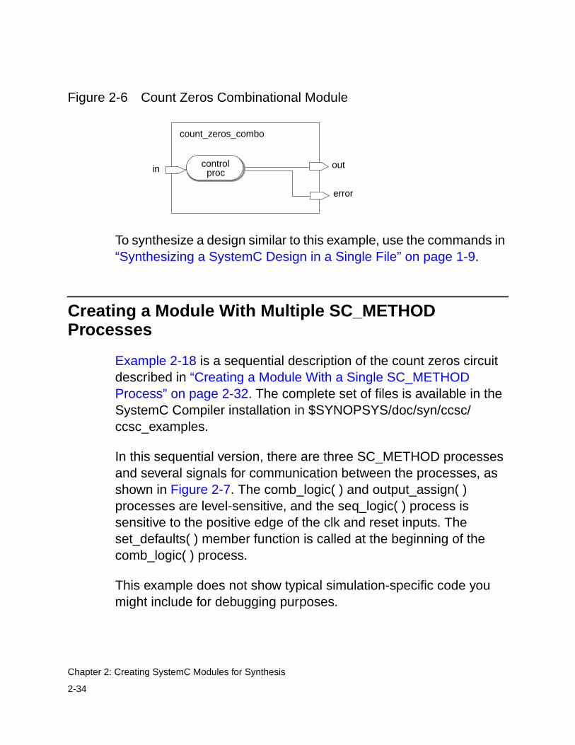
2-34
Chapter 2: Creating SystemC Modules for Synthesis
Figure 2-6 Count Zeros Combinational Module
To synthesize a design similar to this example, use the commands in“Synthesizing a SystemC Design in a Single File” on page 1-9.
Creating a Module With Multiple SC_METHODProcesses
Example 2-18 is a sequential description of the count zeros circuitdescribed in “Creating a Module With a Single SC_METHODProcess” on page 2-32. The complete set of files is available in theSystemC Compiler installation in $SYNOPSYS/doc/syn/ccsc/ccsc_examples.
In this sequential version, there are three SC_METHOD processesand several signals for communication between the processes, asshown in Figure 2-7. The comb_logic( ) and output_assign( )processes are level-sensitive, and the seq_logic( ) process issensitive to the positive edge of the clk and reset inputs. Theset_defaults( ) member function is called at the beginning of thecomb_logic( ) process.
This example does not show typical simulation-specific code youmight include for debugging purposes.
count_zeros_combo
out
error
in controlproc

2-35
Creating a Module With Multiple SC_METHOD Processes
Figure 2-7 Count Zeros Sequential Module
Example 2-18 Count Zeros Sequential Version/****count_zeros_seq.h file****/#include "systemc.h"
#define ZEROS_WIDTH 4#define MAX_BIT_READ 7
SC_MODULE(count_zeros_seq) { sc_in<bool> data, reset, read, clk; sc_out<bool> is_legal, data_ready; sc_out<sc_uint<ZEROS_WIDTH> > zeros;
sc_signal<bool> new_data_ready, new_is_legal, new_seenZero, new_seenTrailing; sc_signal<bool> seenZero, seenTrailing; sc_signal<bool> is_legal_s, data_ready_s; sc_signal<sc_uint<ZEROS_WIDTH> > new_zeros, zeros_s; sc_signal<sc_uint<ZEROS_WIDTH - 1> > bits_seen, new_bits_seen;
// Processes void comb_logic(); void seq_logic(); void assign_outputs();
// Helper functions void set_defaults();
count_zeros
seqlogic
outputassign
dataread
resetclk
zeros
data_ready
is_legal
comblogic
Signalsis_legal_s
seenTrailingseenZero
zeros_sbits_seennew_zeros
Signalsdata_ready_sis_legal_s
new_data_readynew_is_legalnew_seenZeronew_seenTrailingnew_bits_seen
zeros_sdata_ready_s

2-36
Chapter 2: Creating SystemC Modules for Synthesis
SC_CTOR(count_zeros_seq) { SC_METHOD(comb_logic); sensitive << data << read << is_legal_s << data_ready_s; sensitive << seenTrailing << seenZero << zeros_s << bits_seen;
SC_METHOD(seq_logic); sensitive_pos << clk << reset;
SC_METHOD(assign_outputs); sensitive << is_legal_s << data_ready_s << zeros_s; }};
/****count_zeros_seq.cpp file****/#include "count_zeros_seq.h"
/* * SC_METHOD: comb_logic() * finds a singular run of zeros and counts them */void count_zeros_seq::comb_logic() { set_defaults(); if (read.read()) { if (seenTrailing && (data.read() == 0)) { new_is_legal = false; new_zeros = 0; new_data_ready = true; } else if (seenZero && (data.read() == 1)) { new_seenTrailing = true; } else if (data.read() == 0) { new_seenZero = true; new_zeros = zeros_s.read() + 1; }
if (bits_seen.read() == MAX_BIT_READ){ new_data_ready = true; }else{ new_bits_seen = bits_seen.read() + 1; } }}
/* * SC_METHOD: seq_logic() * All registers have asynchronous resets

2-37
Creating a Module With Multiple SC_METHOD Processes
*/void count_zeros_seq::seq_logic() { if (reset) { zeros_s = 0; bits_seen = 0; seenZero = false; seenTrailing = false; is_legal_s = true; data_ready_s = false; } else { zeros_s = new_zeros; bits_seen = new_bits_seen; seenZero = new_seenZero; seenTrailing = new_seenTrailing; is_legal_s = new_is_legal; data_ready_s = new_data_ready; }}
/* * SC_METHOD: assign_outputs() * Zero time assignments of signals to their associated outputs */void count_zeros_seq::assign_outputs() { zeros = zeros_s; is_legal = is_legal_s; data_ready = data_ready_s;}
/* * method: set_defaults() * sets the default values of the new_* signals for the comb_logic * process. */void count_zeros_seq::set_defaults() { new_is_legal = is_legal_s; new_seenZero = seenZero; new_seenTrailing = seenTrailing; new_zeros = zeros_s; new_bits_seen = bits_seen; new_data_ready = data_ready_s;}
To synthesize a design similar to this example, use the commands in“Synthesizing a SystemC Design in a Single File” on page 1-9.

2-38
Chapter 2: Creating SystemC Modules for Synthesis
Creating a Hierarchical RTL Module
You can create a hierarchical module with multiple instantiatedmodules. The lower-level modules can contain either SC_METHODprocesses or an SC_CTHREAD behavioral process. The designdescription and the complete set of files are available in the SystemCCompiler installation in $SYNOPSYS/doc/syn/ccsc/ccsc_examples.
The Basics of Hierarchical Module Creation
To create a hierarchical module,
1. Create data members in the top-level module that are pointers tothe instantiated modules.
2. Allocate the instantiated modules inside the constructor of thetop-level module, giving each instance a unique name.
3. Bind the ports of the instantiated modules to the ports or signalsof the top-level module. Use either binding by position or bindingby name coding style.
Example 2-19 shows the partial source code of two modules, fir_fsmand fir_data, instantiated in the fir_top module. The relevant code ishighlighted in bold.
Example 2-19 Hierarchical Module With Multiple RTL Modules/****fir_top.h****/#include <systemc.h>#include "fir_fsm.h"#include "fir_data.h"
SC_MODULE(fir_top) {
sc_in_clk CLK; sc_in<bool> RESET; sc_in<bool> IN_VALID; sc_in<int> SAMPLE;
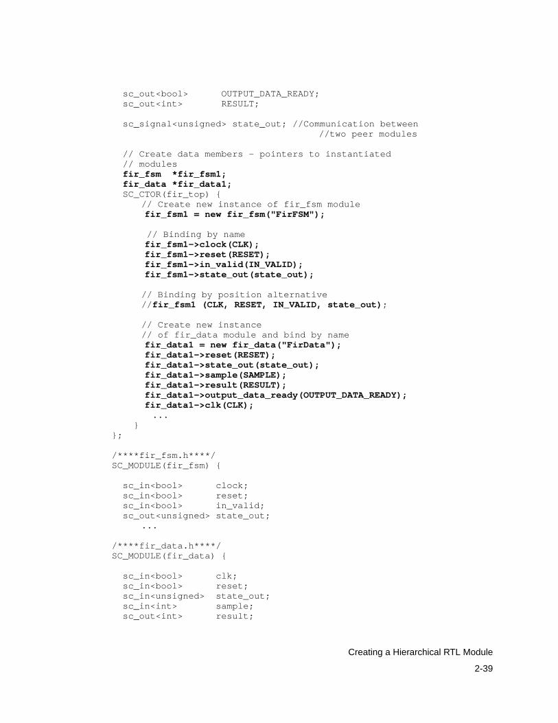
2-39
Creating a Hierarchical RTL Module
sc_out<bool> OUTPUT_DATA_READY; sc_out<int> RESULT;
sc_signal<unsigned> state_out; //Communication between//two peer modules
// Create data members - pointers to instantiated // modulesfir_fsm *fir_fsm1;fir_data *fir_data1;
SC_CTOR(fir_top) {// Create new instance of fir_fsm modulefir_fsm1 = new fir_fsm("FirFSM");
// Binding by namefir_fsm1->clock(CLK);fir_fsm1->reset(RESET);fir_fsm1->in_valid(IN_VALID);fir_fsm1->state_out(state_out);
// Binding by position alternative//fir_fsm1 (CLK, RESET, IN_VALID, state_out);
// Create new instance// of fir_data module and bind by namefir_data1 = new fir_data("FirData");fir_data1->reset(RESET);fir_data1->state_out(state_out);fir_data1->sample(SAMPLE);fir_data1->result(RESULT);fir_data1->output_data_ready(OUTPUT_DATA_READY);fir_data1->clk(CLK); ...
}};
/****fir_fsm.h****/SC_MODULE(fir_fsm) {
sc_in<bool> clock; sc_in<bool> reset; sc_in<bool> in_valid; sc_out<unsigned> state_out;
...
/****fir_data.h****/SC_MODULE(fir_data) {
sc_in<bool> clk; sc_in<bool> reset; sc_in<unsigned> state_out; sc_in<int> sample; sc_out<int> result;

2-40
Chapter 2: Creating SystemC Modules for Synthesis
sc_out<bool> output_data_ready;...
Creating an Integrated RTL and Behavioral Module
Creating an integrated RTL and behavioral module is similar tocreating a hierarchical RTL module. Example 2-20 shows anintegrated module, all_top, that contains an instance of thehierarchical RTL fir_rtl module in Example 2-19 on page 2-38 and aninstance of a behavioral version fir_beh of the FIR filter shown inExample 2-21 on page 2-41. The design description and completeset of files are available in the SystemC Compiler installation in$SYNOPSYS/doc/syn/ccsc/ccsc_examples.
Example 2-20 FIR Top-Level Integrated Module/****all_top.h file****/
#include <systemc.h>
#include "fir_rtl.h"#include "fir_beh.h"
SC_MODULE(all_top) {
sc_in<bool> reset; sc_in<bool> input_valid;
sc_in<int> sample;
sc_out<int> sample_out_rtl; sc_out<bool> output_ready_rtl; sc_out<int> sample_out_syn; sc_out<bool> output_ready_syn;
sc_in<bool> clk1;
// Instantiates RTL and behavioral models fir_rtl *fir_rtl1; fir_beh *fir_beh1;
SC_CTOR(all_top) {
fir_rtl1 = new fir_rtl("firTOP");

2-41
Creating an Integrated RTL and Behavioral Module
fir_rtl1->reset(reset); fir_rtl1->in_valid(input_valid); fir_rtl1->sample(sample); fir_rtl1->result(sample_out_rtl); fir_rtl1->output_data_ready(output_ready_rtl); fir_rtl1->clk(clk1);
fir_beh1 = new fir_beh("FIR"); fir_beh1->reset(reset); fir_beh1->input_valid(input_valid); fir_beh1->sample(sample); fir_beh1->result(sample_out_syn); fir_beh1->output_data_ready(output_ready_syn); fir_beh1->CLK(clk1); };}
Example 2-21 FIR Behavioral Module/****fir_beh.h file****/
C_MODULE(fir_beh) { sc_in<bool> reset; sc_in<bool> input_valid; sc_in<int> sample; sc_out<bool> output_data_ready; sc_out<int> result; sc_in_clk CLK;
SC_CTOR(fir_beh){ SC_CTHREAD(entry, CLK.pos()); watching(reset.delayed() == true); } void entry();};
/****fir_beh.cpp file****/
include <systemc.h>#include "fir_beh.h"#include "fir_const.h"
void fir_beh::entry() {
sc_int<8> sample_tmp; sc_int<17> pro; sc_int<19> acc; sc_int<8> shift[16];

2-42
Chapter 2: Creating SystemC Modules for Synthesis
// reset watching for (int i=0; i<=15; i++){ // synopsys unroll shift[i] = 0; } result.write(0); output_data_ready.write(false); wait();
// main functionality fir_loop:while(1) {
output_data_ready.write(false); wait_until(input_valid.delayed() == true);
sample_tmp = sample.read(); acc = sample_tmp*coefs[0];
for(int i=14; i>=0; i--) { // synopsys unroll acc += shift[i]*coefs[i+1]; }
for(int i=14; i>=0; i--) { // synopsys unroll shift[i+1] = shift[i]; } shift[0] = sample_tmp; // write output values result.write(acc); output_data_ready.write(true); wait(); }}
To synthesize a design similar to this example, use the commands in“Synthesizing a Design With Integrated Behavioral and RTLModules” on page 1-22.

2-43
Specifying Preserved Functions and Implementing DesignWare Components
Specifying Preserved Functions and ImplementingDesignWare Components
Functions increase the readability of your source code. By default,SystemC Compiler inlines functions, which makes the HDL createdby SystemC Compiler difficult to understand. To improve thereadability of the generated HDL, you can direct SystemC Compilerto preserve a function instead of creating inline code. Or you candirect SystemC Compiler to map a function to a synthetic libraryoperator to be implemented by a DesignWare component.
Note:SystemC Compiler version U-2003.06 supports these featuresonly for the RTL Verilog flow, not the VHDL flow.
Defining a Preserved Function
To preserve a function, insert the preserve_function compilerdirective in your code as the first line in the function body.Example 2-22 shows a preserved function that passes two inputparameters and returns a single output.
Example 2-22 Preserved Function With a Single Output Return Value...sc_uint<8> gpf_modulus(sc_uint<8> A, sc_uint<8> B){// synopsys preserve_function
return A % B;}
The function parameters and return types can be any synthesizabletype (Table 3-3 on page 3-11) or a struct of synthesizable types. Youcan read and write module variables, ports, and signals withoutpassing them as function parameters.
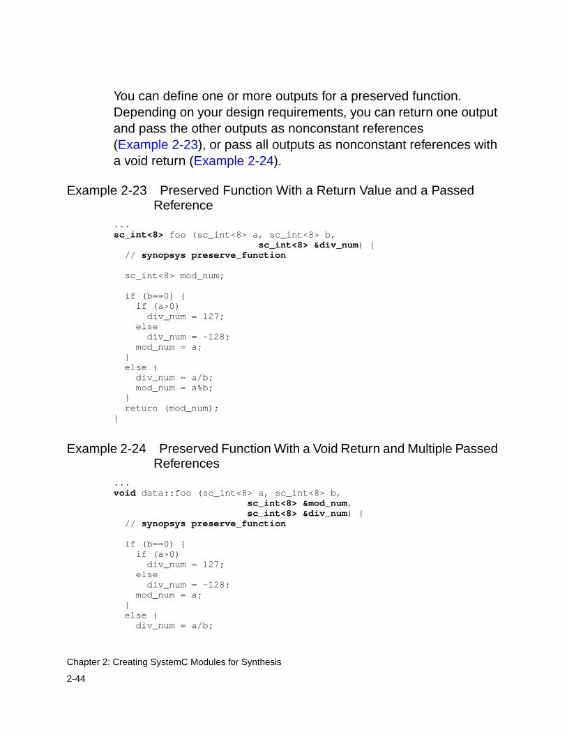
2-44
Chapter 2: Creating SystemC Modules for Synthesis
You can define one or more outputs for a preserved function.Depending on your design requirements, you can return one outputand pass the other outputs as nonconstant references(Example 2-23), or pass all outputs as nonconstant references witha void return (Example 2-24).
Example 2-23 Preserved Function With a Return Value and a PassedReference
...sc_int<8> foo (sc_int<8> a, sc_int<8> b,
sc_int<8> &div_num) { // synopsys preserve_function
sc_int<8> mod_num;
if (b==0) { if (a>0) div_num = 127; else div_num = -128; mod_num = a; } else { div_num = a/b; mod_num = a%b; } return (mod_num);}
Example 2-24 Preserved Function With a Void Return and Multiple PassedReferences
...void data::foo (sc_int<8> a, sc_int<8> b,
sc_int<8> &mod_num,sc_int<8> &div_num) {
// synopsys preserve_function
if (b==0) { if (a>0) div_num = 127; else div_num = -128; mod_num = a; } else { div_num = a/b;

2-45
Specifying Preserved Functions and Implementing DesignWare Components
mod_num = a%b; }}
When you use reference parameters, you need to ensure that youare not creating an alias by mistake. You create an alias by passingthe same object by reference to different parameters. An aliasbetween two outputs creates a short circuit between the outputs.
For example, this problem occurs in the following:
//Definitionvoid abc(int a, const int& b, int& c) { /* synopsys map_to_operator XXX_OP */ ...}
void xyz () { //function call that causes alias abc(x, y, y); ...}
In the above example, parameters b and c are bound to the same yvariable, causing an error.
Another more subtle alias can result from the following function call:
abc(x, a[i], a[j]);
In the above function call, a potential alias occurs, based on thevalue of i and j. In such a situation, use a temporary variable to avoidthe problem; for example,
abc(x, a[i], temp);a[j] = temp;

2-46
Chapter 2: Creating SystemC Modules for Synthesis
Verilog HDL From a Preserved Function
When you execute the compile_systemc command with the-output verilog option for a design with a preserved function,SystemC Compiler creates a Verilog output parameter for a nonvoidreturn type and any nonconstant reference parameters. It createsVerilog input parameters for constant reference parameters and allother parameters. Inout parameters are not supported.
SystemC Compiler creates a Verilog function or task for a preservedfunction. It creates a Verilog function if the preserved function meetsthe following criteria:
• Has a single output returned by the function and no other outputparameters
• Is used in an expression
• Has at least one input parameter
• Does not read from or write to a signal or port
• Does not call another function that fails to meet the above criteria
Example 2-25 shows the Verilog HDL created by SystemC Compilerfrom the SystemC code in Example 2-22. Because the functionmeets the above criteria, a Verilog function is created.
Example 2-25 Verilog HDL Function From a Preserved Function...function [7:0] gpf_modulus; input [7:0] A; input [7:0] B; begin gpf_modulus = A % B; end endfunction
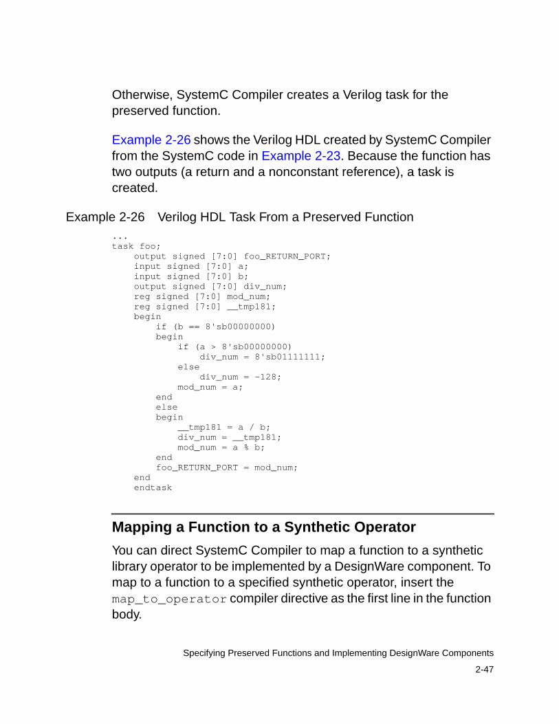
2-47
Specifying Preserved Functions and Implementing DesignWare Components
Otherwise, SystemC Compiler creates a Verilog task for thepreserved function.
Example 2-26 shows the Verilog HDL created by SystemC Compilerfrom the SystemC code in Example 2-23. Because the function hastwo outputs (a return and a nonconstant reference), a task iscreated.
Example 2-26 Verilog HDL Task From a Preserved Function...task foo; output signed [7:0] foo_RETURN_PORT; input signed [7:0] a; input signed [7:0] b; output signed [7:0] div_num; reg signed [7:0] mod_num; reg signed [7:0] __tmp181; begin if (b == 8'sb00000000) begin if (a > 8'sb00000000) div_num = 8'sb01111111; else div_num = -128; mod_num = a; end else begin __tmp181 = a / b; div_num = __tmp181; mod_num = a % b; end foo_RETURN_PORT = mod_num; end endtask
Mapping a Function to a Synthetic Operator
You can direct SystemC Compiler to map a function to a syntheticlibrary operator to be implemented by a DesignWare component. Tomap to a function to a specified synthetic operator, insert themap_to_operator compiler directive as the first line in the functionbody.

2-48
Chapter 2: Creating SystemC Modules for Synthesis
Example 2-27 shows code that instructs SystemC Compiler to use asquare root (SQRT_TC_OP) synthetic operator for synthesis. In thisexample, the SQRT_TC_OP operator has an input port A andreturns the output on the default return port named Z.
Example 2-27 Specifying a Synthetic Operator...sc_uint<8> example::dw_sqrt(sc_int<16> A ) { // synopsys map_to_operator SQRT_TC_OP
#ifdef SIM double temp_d; sc_uint<8> temp;
temp_d = sqrt(fabs(double(A))); root = temp_d;#endif}
You do not need to describe the component’s functionality forsynthesis. After you execute the SystemC Compilercompile_systemc command, this function is replaced by theSQRT_TC_OP operator, provided that it exists in a synthetic libraryspecified in your synthetic library path.
The function body is ignored for synthesis. For simulation, you candescribe the functionality and enclose it in #ifdef and #endifdirectives to indicate the code is excluded for synthesis.
Your function inputs and outputs and their names must match thesynthetic operator ports, which are case-sensitive. Use thereport_synlib command to generate a synthetic library reportshowing the synthetic operator ports and their names.
The function parameters and return types can be any synthesizabletype (see Table 3-3 on page 3-11).

2-49
Specifying Preserved Functions and Implementing DesignWare Components
You can define more than one output for a DesignWare component.For example, you can return one output and pass the other outputsas nonconstant references, as shown in Example 2-28.
Example 2-28 A map_to_operator Function With a Return and a ReferenceParameter
...sc_int<8> data::foo (sc_int<8> A, sc_int<8> B,
sc_int<8> "IENT) {
// synopsys map_to_operator DIV_TC_OP // synopsys return_port_name REMAINDER
sc_int<8> mod_num; if (B==0) { if (A>0) QUOTIENT = 127; else QUOTIENT = -128; mod_num = A; } else { QUOTIENT = A/B; mod_num = A%B; } return mod_num;}
You can also pass all outputs as nonconstant references with a voidreturn, as shown in Example 2-29.
Example 2-29 A map_to_operator Function With Multiple ReferenceParameters
void data::foo (sc_int<8> A, sc_int<8> B,sc_int<8> &REMAINDER,sc_int<8> "IENT) {
// synopsys map_to_operator DIV_TC_OP
if (B==0) { if (A>0) QUOTIENT = 127; else QUOTIENT = -128; REMAINDER = A;

2-50
Chapter 2: Creating SystemC Modules for Synthesis
} else { QUOTIENT = A/B; REMAINDER = A%B; }}
When mapping an output port with a nonvoid return, use thereturn_port_name compiler directive to specify the output portyou want returned by the function, as shown in Example 2-28.Otherwise, it returns the default return port named Z.
Verilog HDL From a Function Mapped to a DesignWareComponent
When you use the compile_systemc command with the -outputverilog option, the function body is converted to Verilog, but it isignored for synthesis.
SystemC Compiler creates a Verilog function or task for a functionthat is mapped to a DesignWare component, using the same criteriadescribed in “Verilog HDL From a Preserved Function” onpage 2-46.

3-1
3Using the Synthesizable Subset 3
This chapter explains the subsets of the SystemC and C/C++language elements and data types that are used for RTL synthesiswith SystemC Compiler. It contains the following sections:
• Converting to a Synthesizable Subset
• Modifying Data for Synthesis
• Recommendations About Modification for Synthesis

3-2
Chapter 3: Using the Synthesizable Subset
Converting to a Synthesizable Subset
To prepare for synthesis, you need to convert all nonsynthesizablecode into synthesizable code. This is required only for functionalitythat is to be synthesized, and not for the testbench or the softwarepart of the system.
Although you can use any SystemC class or C++ construct forsimulation and other stages of the design process, only a subset ofthe language can be used for synthesis. SystemC Compiler does notrecognize nonsynthesizable constructs, and it displays an errormessage if it encounters any of these constructs in your code. Youcan use #ifdef and #endif to comment out code that is needed onlyfor simulation. For example, you can exclude trace and printstatements with these compiler directives.
Excluding Nonsynthesizable Code
SystemC Compiler provides compiler directives you can use in yourcode
• To include synthesis-specific directives
• To exclude or comment out nonsynthesizable andsimulation-specific code so it does not interfere with synthesis
You can isolate nonsynthesizable code or simulation-specific codewith a compiler directive, either the C language #ifdef and #endif(recommended) or a comment starting with the words synopsysand synthesis_off. Example 3-1 shows compiler directives inbold that exclude simulation code for simulation or synthesis.
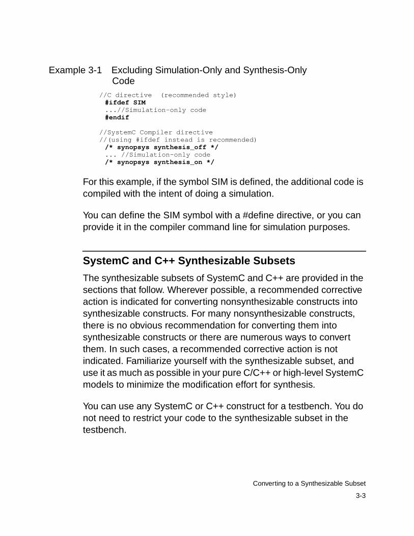
3-3
Converting to a Synthesizable Subset
Example 3-1 Excluding Simulation-Only and Synthesis-OnlyCode
//C directive (recommended style)#ifdef SIM...//Simulation-only code#endif
//SystemC Compiler directive //(using #ifdef instead is recommended)
/* synopsys synthesis_off */... //Simulation-only code/* synopsys synthesis_on */
For this example, if the symbol SIM is defined, the additional code iscompiled with the intent of doing a simulation.
You can define the SIM symbol with a #define directive, or you canprovide it in the compiler command line for simulation purposes.
SystemC and C++ Synthesizable Subsets
The synthesizable subsets of SystemC and C++ are provided in thesections that follow. Wherever possible, a recommended correctiveaction is indicated for converting nonsynthesizable constructs intosynthesizable constructs. For many nonsynthesizable constructs,there is no obvious recommendation for converting them intosynthesizable constructs or there are numerous ways to convertthem. In such cases, a recommended corrective action is notindicated. Familiarize yourself with the synthesizable subset, anduse it as much as possible in your pure C/C++ or high-level SystemCmodels to minimize the modification effort for synthesis.
You can use any SystemC or C++ construct for a testbench. You donot need to restrict your code to the synthesizable subset in thetestbench.
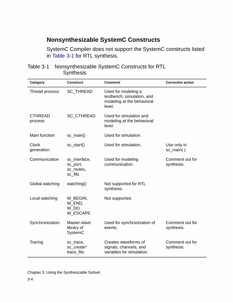
3-4
Chapter 3: Using the Synthesizable Subset
Nonsynthesizable SystemC Constructs
SystemC Compiler does not support the SystemC constructs listedin Table 3-1 for RTL synthesis.
Table 3-1 Nonsynthesizable SystemC Constructs for RTLSynthesis
Category Construct Comment Corrective action
Thread process SC_THREAD Used for modeling atestbench, simulation, andmodeling at the behaviorallevel.
CTHREADprocess
SC_CTHREAD Used for simulation andmodeling at the behaviorallevel.
Main function sc_main() Used for simulation.
Clockgeneration
sc_start() Used for simulation. Use only insc_main( ).
Communication sc_interface,sc_port,sc_mutex,sc_fifo
Used for modelingcommunication.
Comment out forsynthesis.
Global watching watching() Not supported for RTLsynthesis.
Local watching W_BEGIN,W_END,W_DO,W_ESCAPE
Not supported.
Synchronization Master-slavelibrary ofSystemC
Used for synchronization ofevents.
Comment out forsynthesis.
Tracing sc_trace,sc_create*trace_file
Creates waveforms ofsignals, channels, andvariables for simulation.
Comment out forsynthesis.

3-5
Converting to a Synthesizable Subset
Nonsynthesizable C/C++ Constructs
SystemC Compiler does not support the C and C++ constructs listedin Table 3-2 for RTL synthesis.
Table 3-2 Nonsynthesizable C/C++ Constructs
Category Construct Comment Corrective action
Local classdeclaration
Not allowed. Replace.
Nested classdeclaration
Not allowed. Replace.
Derived class Only SystemC modules andprocesses are supported.
Replace.
Dynamicstorageallocation
malloc(),free(), new,new[],delete,delete[]
malloc(), free(), new, new[],delete, and delete[] are notsupported. The new construct isallowed only to instantiate amodule to create hierarchy.
Use static memoryallocation.
Exceptionhandling
try, catch,throw
Not allowed. Comment out.
Recursivefunction call
Not allowed. Replace withiteration.
Functionoverloading
Not allowed (except the classesoverloaded by SystemC).
Replace with uniquefunction calls.
C++ built-infunctions
Math library, I/O library, file I/O,and similar built-in C++functions not allowed.
Replace withsynthesizablefunctions or remove.
Virtual function Not allowed. Replace with anonvirtual function.

3-6
Chapter 3: Using the Synthesizable Subset
Inheritance Not allowed. Create anindependentSC_MODULE.
Multipleinheritance
Not allowed. Create independentmodules.
Member accesscontrolspecifiers
public,protected,private,friend
Allowed in code but ignored forsynthesis. All member access ispublic.
Accessingstructmembers withthe (->) operator
-> operator Not allowed, except for moduleinstantiation.
Replace with accessusing the period (.)operator.
Static member Not allowed. Replace withnonstatic membervariable.
Dereferenceoperator
* and &operators
Not allowed. Replacedereferencing witharray accessing.
for loop commaoperator
, operator The comma operator is notallowed in a for loop definition.
Remove the commaoperators.
Unboundedloop
Not allowed. Replace with abounded loop, suchas a for loop.
Out-of-boundarray access
Not allowed. Replace within-bound arrayaccess.
Operatoroverloading
Not allowed (except the classesoverloaded by SystemC).
Replace overloadingwith unique functioncalls.
Table 3-2 Nonsynthesizable C/C++ Constructs (Continued)
Category Construct Comment Corrective action

3-7
Converting to a Synthesizable Subset
Operator, sizeof sizeof Not allowed. Determine sizestatically for use insynthesis.
Pointer * Pointers are allowed only inhierarchical modules toinstantiate other modules.
Replace all otherpointers with accessto array elements orindividual elements.
Pointer typeconversions
Not allowed. Do not use pointers.Use explicit variablereference.
this pointer this Not allowed. Replace.
Reference, C++ & Allowed only for passingparameters to functions.
Replace in all othercases.
Referenceconversion
Reference conversion issupported for implicitconversion of signals only.
Replace in all othercases.
Static variable Not allowed in functions.
User-definedtemplate class
Only SystemC templatesclasses such as sc_int<> aresupported.
Replace.
Explicituser-definedtype conversion
The C++ built-in types andSystemC types are supportedonly for explicit conversion.
Replace in all othercases.
Type casting atruntime
Not allowed. Replace.
Typeidentification atruntime
Not allowed. Replace.
Unconditionalbranching
goto Not allowed. Replace.
Table 3-2 Nonsynthesizable C/C++ Constructs (Continued)
Category Construct Comment Corrective action

3-8
Chapter 3: Using the Synthesizable Subset
Modifying Data for Synthesis
A pure C/C++ model or a high-level SystemC model typically usesnative C++ types or aggregates (structures) of such types. NativeC++ types such as int, char, bool, and long have fixed, platform-dependent widths, which are often not the correct width for efficienthardware. For example, you might need only a 6-bit integer for aparticular operation, instead of the native C++ 32-bit integer. Inaddition, C++ does not support four-valued logic vectors, operationssuch as concatenation, and other features that are needed toefficiently describe hardware operations.
SystemC provides a set of limited-precision and arbitrary-precisiondata types that allows you to create integers, bit vectors, and logicvectors of any length. SystemC also supports all common operationson these data types.
Unions Not allowed. Replace with structs.
Global variable Not supported for synthesis. Replace with localvariables.
Membervariable
Member variables accessed bytwo or more SC_METHODprocesses are not supported.However, access to membervariables by only one process issupported.
Use signals instead ofvariables forcommunicationbetween processes.
Volatile variable Not allowed. Use only nonvolatilevariables.
Table 3-2 Nonsynthesizable C/C++ Constructs (Continued)
Category Construct Comment Corrective action
3-9
Modifying Data for Synthesis
To modify a SystemC model for synthesis, you need to evaluate allvariable declarations, formal parameters, and return types of allfunctions to determine the appropriate data type and the appropriatewidths of each data type. The following sections providerecommendations about the appropriate data type to use and when.Selecting the data widths is a design decision, and it is typically atradeoff between the cost of hardware and the required precision.This decision is, therefore, up to you.
Synthesizable Data Types
C++ is a strongly typed language. Every constant, port, signal,variable, function return type, and parameter is declared as a datatype, such as bool or sc_int<n>. Therefore, it is important that youuse the correct data types in expressions.
Nonsynthesizable Data Types
All SystemC and C++ data types, except the following types, can beused for RTL synthesis:
• Floating-point types such as float and double
• Fixed-point types sc_fixed, sc_ufixed, sc_fix, and sc_ufix
• Access types such as pointers
• File types such as FILE
• I/O streams such as stdout and cout

3-10
Chapter 3: Using the Synthesizable Subset
Recommended Data Types for Synthesis
For best synthesis, use appropriate data types and bit-widths soSystemC Compiler does not build unnecessary hardware.
The following are some general recommendations about data typeselection:
• For a single-bit variable, use the native C++ type bool.
• For variables with a width of 64 bits or less, use the sc_int orsc_uint data type. Use sc_uint for all logic and unsignedarithmetic operations. Use sc_int for signed arithmetic operationsas well as for logic operations. These types produce the fastestsimulation runtimes of the SystemC types.
• For variables larger than 64 bits, use sc_bigint or sc_biguint if youwant to do arithmetic operations with these variables.
• Use sc_logic or sc_lv only when you need to model three-statesignals or buses. When you use these data types, avoidcomparison with X and Z values in your synthesizable code,because such comparisons are not synthesizable. Examples ofthree-state inference are provided in “Three-State Inference” onpage 4-47.
• Use native C++ integer types for loop counters.Recommendations about loops are provided in “Loops” onpage 4-53.
• Use the native C++ data types with caution, because their size isplatform dependent. For example, on most platforms, a char is 8bits wide, a short is 16 bits wide, and both an int and a long are32 bits wide. An int, however, can be 16, 32, or 64 bits wide.
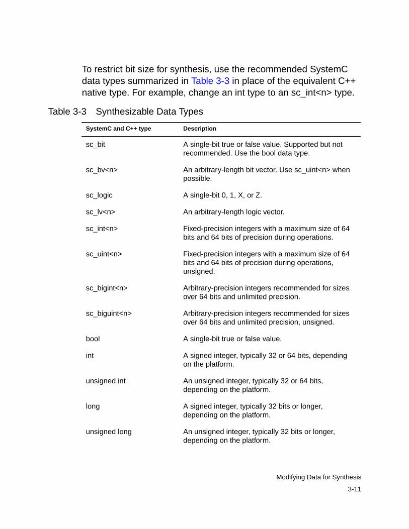
3-11
Modifying Data for Synthesis
To restrict bit size for synthesis, use the recommended SystemCdata types summarized in Table 3-3 in place of the equivalent C++native type. For example, change an int type to an sc_int<n> type.
Table 3-3 Synthesizable Data Types
SystemC and C++ type Description
sc_bit A single-bit true or false value. Supported but notrecommended. Use the bool data type.
sc_bv<n> An arbitrary-length bit vector. Use sc_uint<n> whenpossible.
sc_logic A single-bit 0, 1, X, or Z.
sc_lv<n> An arbitrary-length logic vector.
sc_int<n> Fixed-precision integers with a maximum size of 64bits and 64 bits of precision during operations.
sc_uint<n> Fixed-precision integers with a maximum size of 64bits and 64 bits of precision during operations,unsigned.
sc_bigint<n> Arbitrary-precision integers recommended for sizesover 64 bits and unlimited precision.
sc_biguint<n> Arbitrary-precision integers recommended for sizesover 64 bits and unlimited precision, unsigned.
bool A single-bit true or false value.
int A signed integer, typically 32 or 64 bits, dependingon the platform.
unsigned int An unsigned integer, typically 32 or 64 bits,depending on the platform.
long A signed integer, typically 32 bits or longer,depending on the platform.
unsigned long An unsigned integer, typically 32 bits or longer,depending on the platform.

3-12
Chapter 3: Using the Synthesizable Subset
SystemC to VHDL Data Type Conversion
The compile_systemc command with the -rtl -format vhdloption converts the SystemC data types to VHDL data types, aslisted in Table 3-4.
char 8-bit signed character, platform-dependent.
unsigned char 8-bit unsigned character, platform-dependent.
short A signed short integer, typically 16 bits, dependingon the platform.
unsigned short An unsigned short integer, typically 16 bits,depending on the platform.
struct A user-defined aggregate of synthesizable datatypes.
enum A user-defined enumerated data type associatedwith an integer constant.
Table 3-4 SystemC to VHDL Data Type Conversion
SystemC data type VHDL data type
bool std_logic
sc_int signed
sc_uint unsigned
Table 3-3 Synthesizable Data Types (Continued)
SystemC and C++ type Description

3-13
Modifying Data for Synthesis
Using SystemC Data Types
Use the SystemC data type operators to access individual bits of avalue.
Fixed-Precision and Arbitrary-Precision Data TypeOperators
Table 3-5 lists the operators available for the SystemC sc_int andsc_uint fixed-precision and sc_bigint and sc_biguint arbitrary-precision integer data types.
Note:The reduction and_reduce(), or_reduce(), and xor_reduce()operators are not available for the fixed- and arbitrary-precisiondata types.
Table 3-5 SystemC Integer Data Type Operators
Operators
Bitwise &(and), |(or), ^(xor), and ~(not)
Bitwise <<(shift left) and >>(shift right)
Assignment =, &=, |=, ^=, +=, -=, *=, /=, and %=
Equality ==, !=
Relational <, <=, >, and >=
Autoincrement ++ and autodecrement --
Bit selection [x]
Part selection range (x,y)
Concatenation (x,y)
Type conversion: to_uint( ) and to_int( )
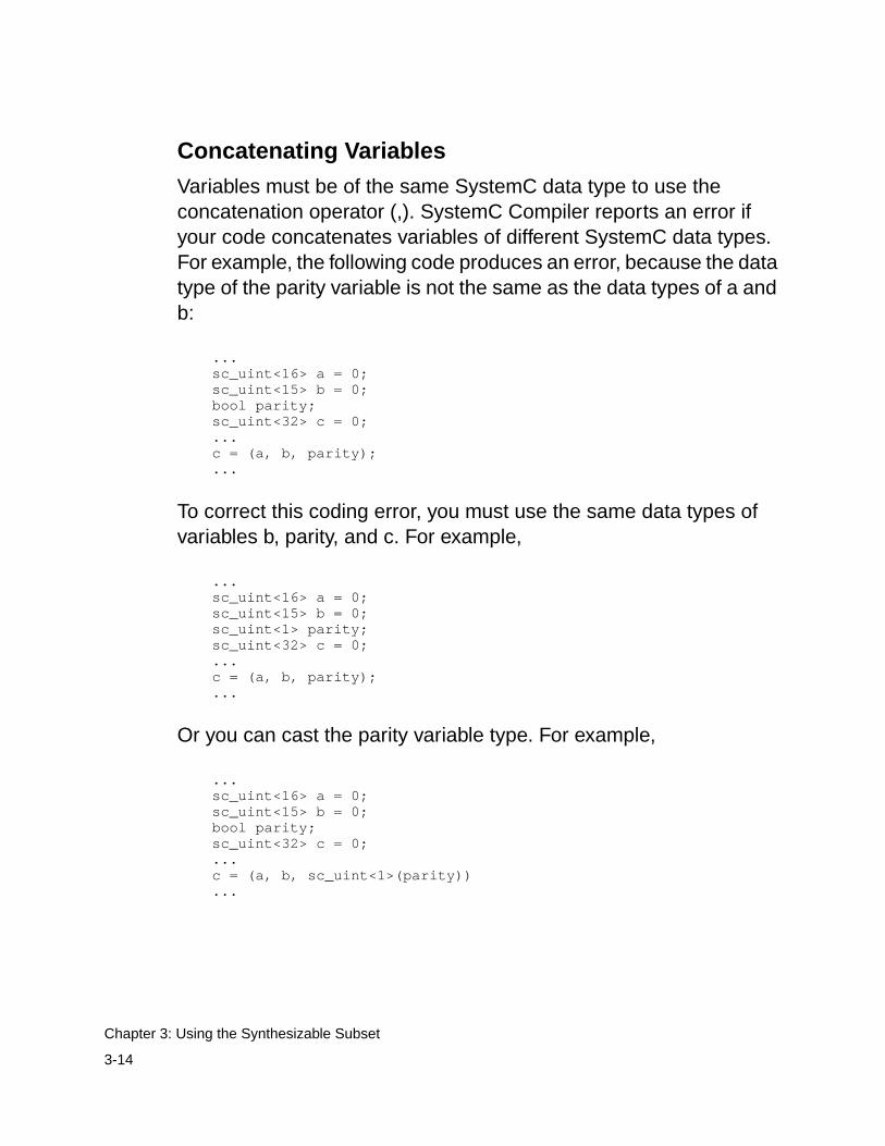
3-14
Chapter 3: Using the Synthesizable Subset
Concatenating Variables
Variables must be of the same SystemC data type to use theconcatenation operator (,). SystemC Compiler reports an error ifyour code concatenates variables of different SystemC data types.For example, the following code produces an error, because the datatype of the parity variable is not the same as the data types of a andb:
... sc_uint<16> a = 0; sc_uint<15> b = 0; bool parity; sc_uint<32> c = 0; ... c = (a, b, parity); ...
To correct this coding error, you must use the same data types ofvariables b, parity, and c. For example,
... sc_uint<16> a = 0; sc_uint<15> b = 0; sc_uint<1> parity; sc_uint<32> c = 0; ... c = (a, b, parity); ...
Or you can cast the parity variable type. For example,
... sc_uint<16> a = 0; sc_uint<15> b = 0; bool parity; sc_uint<32> c = 0; ... c = (a, b, sc_uint<1>(parity)) ...

3-15
Modifying Data for Synthesis
The equality operator (=) has a higher precedence than theconcatenation operator (,). Enclose concatenation operations in anexpression within parentheses to ensure that the expression isevaluated correctly. For example, in the following expression, a = b isevaluated before b and c are concatenated:
a = b, c;
To ensure that b and c are concatenated before the result is assignedto c, enclose (b, c) within parentheses, as follows:
a = (b, c);
Using a Variable to Read and Write Bits
You can read or write all bits of a port or signal. You cannot read orwrite the individual bits, regardless of the data type, because thisoperation is not allowed in SystemC.
To do a bit-select on a port or signal, read the value into a temporaryvariable and do a bit-select on the temporary variable. Example 3-2shows reading from a port into a temporary variable and writingselected bits to an output port.
Example 3-2 Reading and Writing Bits With a Variable#include "systemc.h"
SC_MODULE(bit_range) { sc_in<sc_int<8> > in; sc_out<sc_int<5> > out;
sc_int<8> var_i; sc_signal<sc_int<5> > sig_i;
void entry() { var_i = in.read(); sig_i = var_i.range(6,2); out.write(var_i.range(1,5)); }
SC_CTOR(bit_range) {

3-16
Chapter 3: Using the Synthesizable Subset
SC_METHOD(entry); sensitive << in; }};
Example 3-2 reads the value of port in into temporary variable var_iand writes bits 2 through 6 of var_i into signal sig_i. Then it writes bits1 through 5 to port out.
Using Constants
SystemC Compiler supports constant variables local to a function. Itsupports static constants only at the global level. Example 3-3 showssome examples of using constants in your design.
Example 3-3 Defining a Bit-Width at the Global Level#include <systemc.h>
// The keyword static is allowed only for// constants in the global namespace.static const sc_uint<8> my_array1[2] = {1,2};#define BITWIDTH1 4#define BITWIDTH2 8
SC_MODULE(rtl_const) {
sc_in<sc_uint<BITWIDTH1> > addr; sc_out<sc_uint<BITWIDTH2> > data1; sc_out<sc_uint<BITWIDTH2> > data2;
sc_uint<8> my_array2[2];
void my() { const sc_uint<8> my_array2[2] = {3,4}; const int const2 = 4;
data1 = my_array1[0]; data2 = my_array2[addr.read()]; }
SC_CTOR(rtl_const) { SC_METHOD(my); sensitive << addr; }};
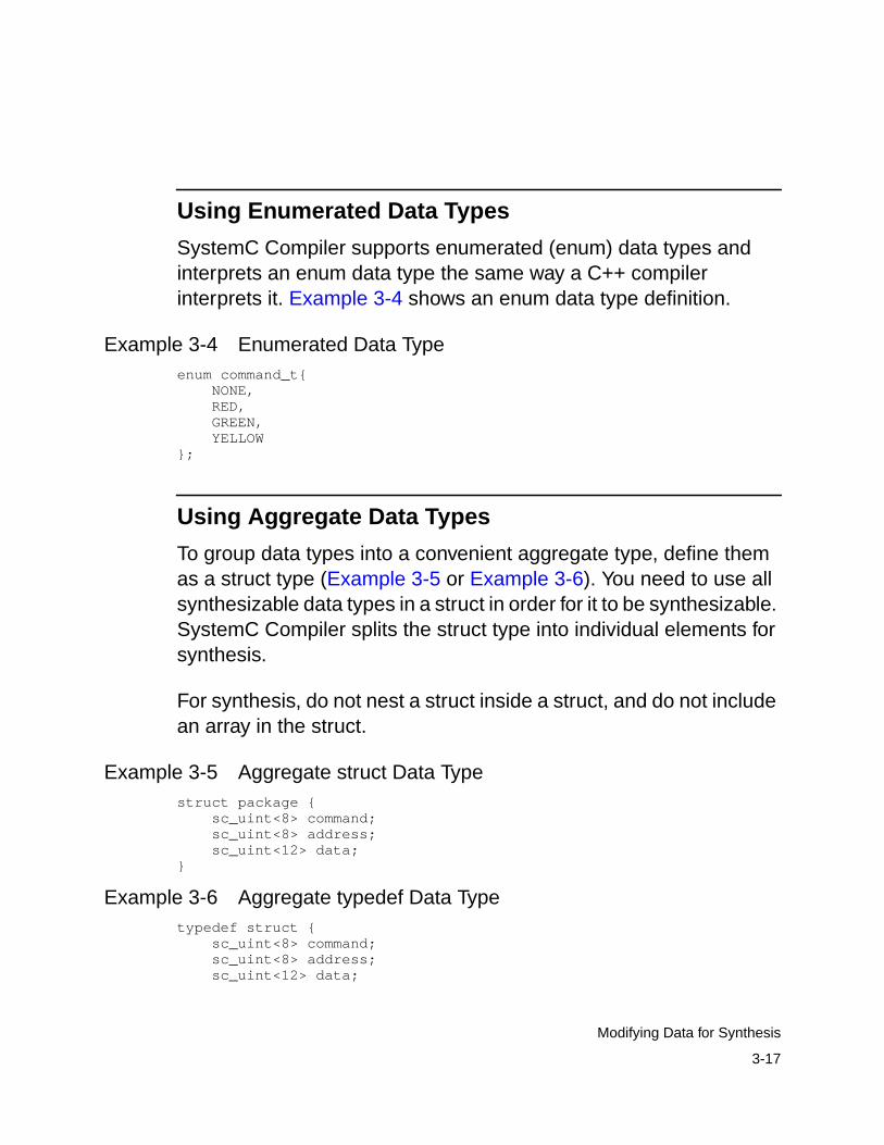
3-17
Modifying Data for Synthesis
Using Enumerated Data Types
SystemC Compiler supports enumerated (enum) data types andinterprets an enum data type the same way a C++ compilerinterprets it. Example 3-4 shows an enum data type definition.
Example 3-4 Enumerated Data Typeenum command_t{ NONE, RED, GREEN, YELLOW};
Using Aggregate Data Types
To group data types into a convenient aggregate type, define themas a struct type (Example 3-5 or Example 3-6). You need to use allsynthesizable data types in a struct in order for it to be synthesizable.SystemC Compiler splits the struct type into individual elements forsynthesis.
For synthesis, do not nest a struct inside a struct, and do not includean array in the struct.
Example 3-5 Aggregate struct Data Typestruct package { sc_uint<8> command; sc_uint<8> address; sc_uint<12> data;}
Example 3-6 Aggregate typedef Data Typetypedef struct { sc_uint<8> command; sc_uint<8> address; sc_uint<12> data;
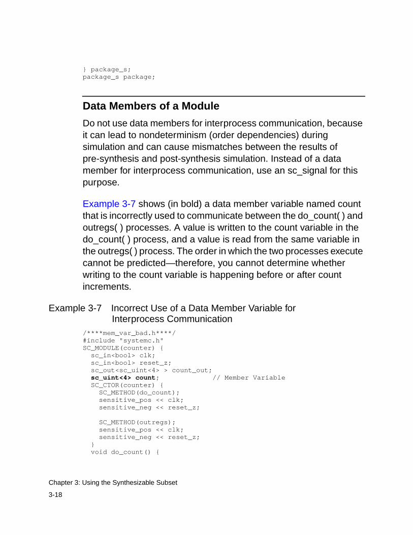
3-18
Chapter 3: Using the Synthesizable Subset
} package_s;package_s package;
Data Members of a Module
Do not use data members for interprocess communication, becauseit can lead to nondeterminism (order dependencies) duringsimulation and can cause mismatches between the results ofpre-synthesis and post-synthesis simulation. Instead of a datamember for interprocess communication, use an sc_signal for thispurpose.
Example 3-7 shows (in bold) a data member variable named countthat is incorrectly used to communicate between the do_count( ) andoutregs( ) processes. A value is written to the count variable in thedo_count( ) process, and a value is read from the same variable inthe outregs( ) process. The order in which the two processes executecannot be predicted—therefore, you cannot determine whetherwriting to the count variable is happening before or after countincrements.
Example 3-7 Incorrect Use of a Data Member Variable forInterprocess Communication
/****mem_var_bad.h****/#include "systemc.h"SC_MODULE(counter) { sc_in<bool> clk; sc_in<bool> reset_z; sc_out<sc_uint<4> > count_out;sc_uint<4> count; // Member Variable
SC_CTOR(counter) { SC_METHOD(do_count); sensitive_pos << clk; sensitive_neg << reset_z;
SC_METHOD(outregs); sensitive_pos << clk; sensitive_neg << reset_z; } void do_count() {

3-19
Modifying Data for Synthesis
if (reset.read() == 0) {count = 0;
}else{count++;
} } void outregs() { if (reset.read() == 0){
count_out.write(0); }else{
count_out.write(count); } }
};
To eliminate the nondeterminism of count in Example 3-7, changecount to an sc_signal, as shown in bold in Example 3-8. Notice thatthe only change in the code is the type declaration of count.
Example 3-8 Correct Use of a Signal for InterprocessCommunication
/****mem_var_good.h****/#include "systemc.h"
SC_MODULE(counter) { sc_in<bool> clk; sc_in<bool> reset_z; sc_out<sc_uint<4> > count_out;
// Signal for interprocess communicationsc_signal<sc_uint<4> > count;
SC_CTOR(counter) { SC_METHOD(do_count); sensitive_pos << clk; sensitive_neg << reset_z;
SC_METHOD(outregs); sensitive_pos << clk; sensitive_neg << reset_z; } void do_count() { if (reset_z.read() == 0){ count = 0; }else{ count.read() +1; } } void outregs() { if (reset_z.read() == 0){

3-20
Chapter 3: Using the Synthesizable Subset
count_out.write(0); }else{ count_out.write(count); } }
};
Assigning to Data Members in the Constructor
You can make assignments to data members from within theconstructor. These assignments are treated as constants forsynthesis.
Recommendations About Modification for Synthesis
The following practices are recommended during modification forsynthesis:
• After each modification step, reverify your design to ensure thatyou did not introduce errors during that step.
• Although it is recommended that you thoroughly define forsynthesis at each modification stage, you might prefer a differenttechnique. For example, during data modification, you canchange one data type at a time and evaluate the impact onsynthesizability and the quality of results with SystemC Compiler.Similarly, you might want to replace one nonsynthesizableconstruct with a synthesizable construct and reverify the designbefore replacing the next nonsynthesizable construct.
4-1
4RTL Coding Guidelines 4
This chapter provides SystemC RTL coding guidelines. Theexamples in this chapter use the lsi_10k sample target libraryprovided in the $SYNOPSYS/libraries/syn directory.
It contains the following sections:
• Register Inference
• Multibit Inference
• Multiplexer Inference
• Three-State Inference
• Loops
• State Machines
4-2
Chapter 4: RTL Coding Guidelines
Register Inference
Register inference allows you to use sequential logic in your designsand keep your designs technology independent. A register is anarray of 1-bit memory devices. A latch is a level-sensitive memorydevice, and a flip-flop is an edge-triggered memory device. Use thecoding guidelines in this section to control flip-flop and latchinference.
As a recommended design practice, whenever you infer registers,make certain that the clock and data inputs to the registers can bedirectly controlled from the ports of the design. This ensures that youcan initialize your design easily during simulation as well as in theactual circuit. You can, of course, infer registers with a set and areset, which makes the task of register initialization easier and ishighly recommended.
Flip-Flop Inference
SystemC Compiler can infer D flip-flops, JK flip-flops, and toggleflip-flops. The following sections provide details about each of theseflip-flop types.
Simple D Flip-Flop
To infer a simple D flip-flop, make the SC_METHOD processsensitive to only one edge of the clock signal. To infer arising-edge-triggered flip-flop, make the process sensitive to thepositive edge of the clock, and make the process sensitive to thenegative edge to infer a falling-edge-triggered flip-flop.
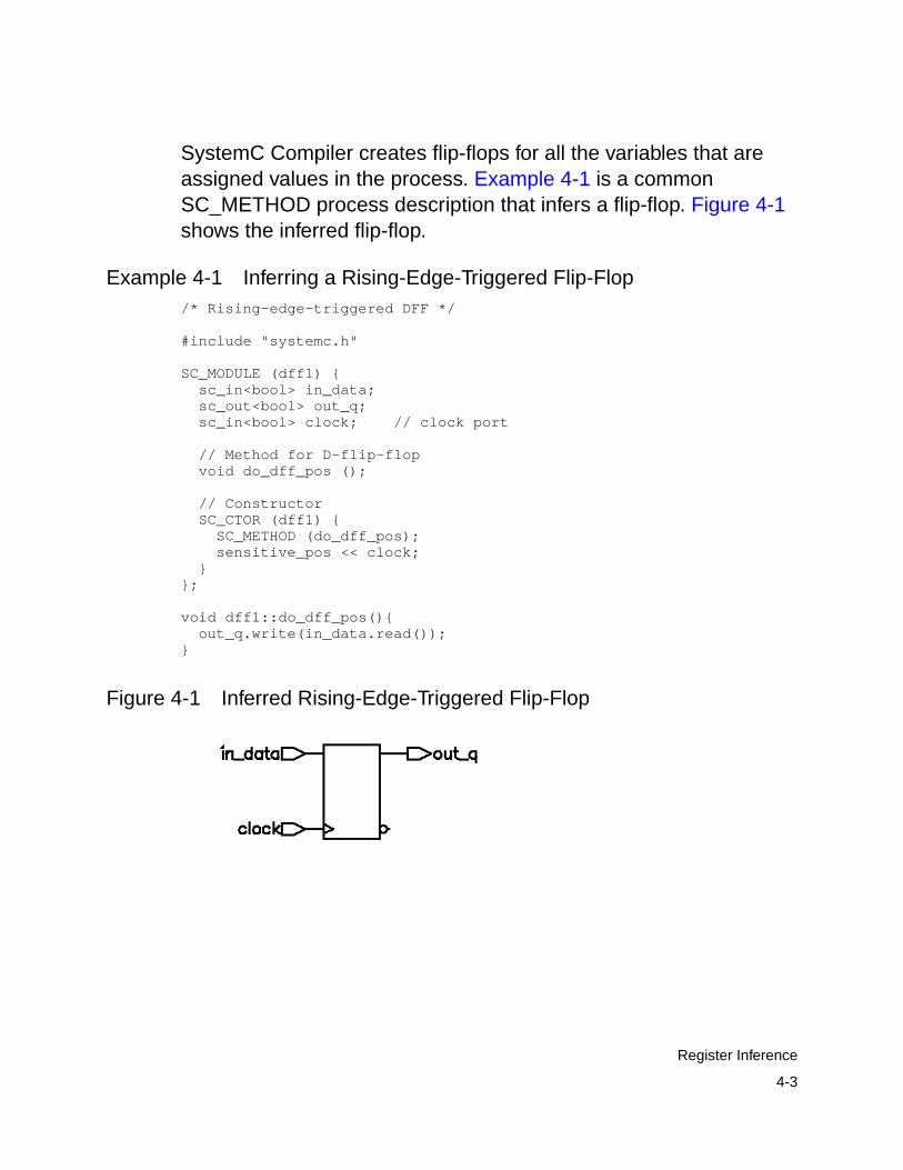
4-3
Register Inference
SystemC Compiler creates flip-flops for all the variables that areassigned values in the process. Example 4-1 is a commonSC_METHOD process description that infers a flip-flop. Figure 4-1shows the inferred flip-flop.
Example 4-1 Inferring a Rising-Edge-Triggered Flip-Flop/* Rising-edge-triggered DFF */
#include "systemc.h"
SC_MODULE (dff1) { sc_in<bool> in_data; sc_out<bool> out_q; sc_in<bool> clock; // clock port
// Method for D-flip-flop void do_dff_pos ();
// Constructor SC_CTOR (dff1) { SC_METHOD (do_dff_pos); sensitive_pos << clock; }};
void dff1::do_dff_pos(){ out_q.write(in_data.read());}
Figure 4-1 Inferred Rising-Edge-Triggered Flip-Flop

4-4
Chapter 4: RTL Coding Guidelines
D Flip-Flop With an Active-High Asynchronous Set orReset
To infer a D flip-flop with an asynchronous set or reset, include edgeexpressions for the clock and the asynchronous signals in thesensitivity list of the SC_METHOD process constructor. Specify theasynchronous signal conditions with an if statement in theSC_METHOD process definition. Example 4-2 shows a typicalasynchronous specification. Specify the asynchronous branchconditions before you specify the synchronous branch conditions.
Example 4-2 is the SystemC description for a D flip-flop with anactive-high asynchronous reset. Figure 4-2 shows the inferredflip-flop.
Example 4-2 D Flip-Flop With an Active-High AsynchronousReset
/* Rising-edge-triggered DFF */
#include "systemc.h"
SC_MODULE (dff3) { sc_in<bool> in_data, reset; sc_out<bool> out_q; sc_in<bool> clock; // clock port
void do_dff_pos ();
// Constructor SC_CTOR (dff3) { SC_METHOD (do_dff_pos); sensitive_pos << clock << reset; }};
void dff3::do_dff_pos () { if (reset.read()){ out_q.write(0); }else{ out_q.write(in_data.read()); }}

4-5
Register Inference
Figure 4-2 D Flip-Flop With an Active-High AsynchronousReset
D Flip-Flop With an Active-Low Asynchronous Setor Reset
Example 4-3 is a SystemC description for a D flip-flop with anactive-low asynchronous reset. Figure 4-3 shows the inferredflip-flop.
Example 4-3 D Flip-Flop With an Active-Low AsynchronousReset
/* Rising-edge-triggered DFF with active-low reset */
#include "systemc.h"
SC_MODULE (dff3a) { sc_in<bool> in_data, reset; sc_out<bool> out_q; sc_in<bool> clock; // clock port
void do_dff_pos ();
// Constructor SC_CTOR (dff3a) { SC_METHOD (do_dff_pos); sensitive_pos << clock; sensitive_neg << reset; }};
void dff3a::do_dff_pos () { if (reset.read() == 0){ out_q.write(0);
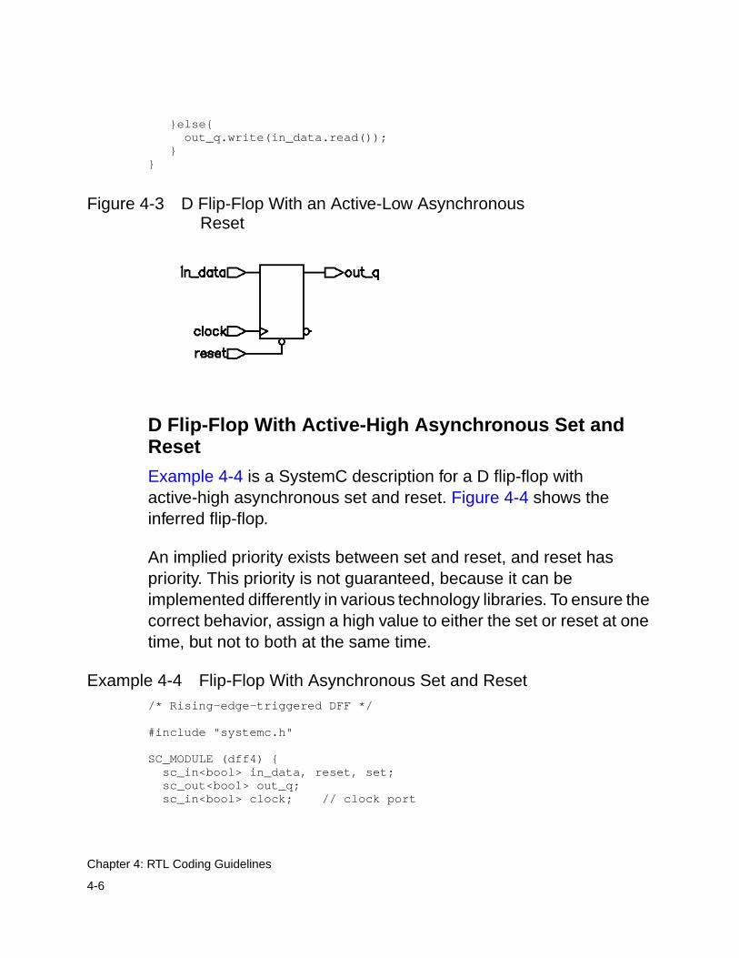
4-6
Chapter 4: RTL Coding Guidelines
}else{ out_q.write(in_data.read()); }}
Figure 4-3 D Flip-Flop With an Active-Low AsynchronousReset
D Flip-Flop With Active-High Asynchronous Set andReset
Example 4-4 is a SystemC description for a D flip-flop withactive-high asynchronous set and reset. Figure 4-4 shows theinferred flip-flop.
An implied priority exists between set and reset, and reset haspriority. This priority is not guaranteed, because it can beimplemented differently in various technology libraries. To ensure thecorrect behavior, assign a high value to either the set or reset at onetime, but not to both at the same time.
Example 4-4 Flip-Flop With Asynchronous Set and Reset/* Rising-edge-triggered DFF */
#include "systemc.h"
SC_MODULE (dff4) { sc_in<bool> in_data, reset, set; sc_out<bool> out_q; sc_in<bool> clock; // clock port

4-7
Register Inference
void do_dff_pos ();
// Constructor SC_CTOR (dff4) { SC_METHOD (do_dff_pos); sensitive_pos << clock << reset << set; }};
void dff4::do_dff_pos () { if (reset.read()){ out_q.write(0); }else if (set.read()){ out_q.write(1); }else{ out_q.write(in_data.read()); }}
Figure 4-4 Flip-Flop With Asynchronous Set and Reset
D Flip-Flop With Synchronous Set or Reset
The previous examples illustrated how to infer a D flip-flop withasynchronous controls—one way to initialize or control the state of asequential device. You can also synchronously reset or set a flip-flop.
If the target technology library does not have a D flip-flop with asynchronous reset, a D flip-flop with synchronous reset logic as theinput to the D pin of the flip-flop is inferred. If the reset (or set) logicis not directly in front of the D pin of the flip-flop, initializationproblems can occur during gate-level simulation of the design.

4-8
Chapter 4: RTL Coding Guidelines
To specify a synchronous set or reset input, do not include it in thesensitivity list. Describe the synchronous set or reset test and actionin an if statement. Example 4-5 is a SystemC description for a Dflip-flop with synchronous reset. Figure 4-5 shows the inferredflip-flop.
Example 4-5 D Flip-Flop With Synchronous Reset/* Rising-edge-triggered DFF */
#include "systemc.h"
SC_MODULE (dff5) { sc_in<bool> in_data, reset; sc_out<bool> out_q; sc_in<bool> clock; // clock port
// Method for D-flip-flop void dff ();
// Constructor SC_CTOR (dff5) { SC_METHOD (dff); sensitive_pos << clock; }};
void dff5::dff(){ if (reset.read()){ out_q.write(0); }else{ out_q.write(in_data.read()); }}
Figure 4-5 D Flip-Flop With Synchronous Reset

4-9
Register Inference
Inferring JK Flip-Flops
Use a switch…case statement to infer JK flip-flops.
JK Flip-Flop With Synchronous Set and Reset. Example 4-6shows the SystemC code that implements the JK flip-flop truth tablein Table 4-1. In the JK flip-flop, the J and K signals are similar toactive-high synchronous set and reset. Figure 4-6 shows the inferredflip-flop.
Example 4-6 JK Flip-Flop/* Rising-edge-triggered JK FF */
#include "systemc.h"
SC_MODULE (jkff1) { sc_in<bool> j, k; sc_inout<bool> q; // inout to read q for toggle sc_in<bool> clk; // clock port
// Method for D-flip-flop void jk_flop ();
// Constructor SC_CTOR (jkff1) { SC_METHOD (jk_flop); sensitive_pos << clk; }};
Table 4-1 Rising-Edge-Triggered JK Flip-Flop Truth Table
J K CLK Qn+1
0 0 Rising Qn
0 1 Rising 0
1 0 Rising 1
1 1 Rising
X X Falling Qn
Qn

4-10
Chapter 4: RTL Coding Guidelines
void jkff1::jk_flop() { sc_uint<2> temp; //temp to create vector temp[1] = j.read( ); temp[0] = k.read( ); switch(temp) { case 0x1: q.write(0); // write a zero break; case 0x2: q.write(1); // write a 1 break; case 0x3: // toggle q.write(!q.read()); break; default: break; // no change }}
Figure 4-6 JK Flip-Flop
JK Flip-Flop With Asynchronous Set and Reset. Example 4-7 isa SystemC description for a JK flip-flop with an active-lowasynchronous set and reset. To specify an asynchronous set orreset, specify the signal in the sensitivity list as shown inExample 4-7. Figure 4-7 shows the inferred flip-flop.
Example 4-7 JK Flip-Flop With Asynchronous Set and Reset/* Rising-edge-triggered JKFF */
#include "systemc.h"
SC_MODULE (jkff2) { sc_in<bool> j, k, set, reset; sc_inout<bool> q; // inout to read q for toggle sc_in<bool> clk; // clock port
// Method for D-flip-flop void jk_flop ();

4-11
Register Inference
// Constructor SC_CTOR (jkff2) { SC_METHOD (jk_flop); sensitive_pos << clk; sensitive_neg << set << reset; }};void jkff2::jk_flop() { sc_uint<2> temp; //temp to create vector if (reset.read()==0){ q.write(0); // reset }else if (set.read()==0){ q.write(1); // set }else { temp[1] = j.read(); temp[0] = k.read(); switch(temp) { case 0x1: q.write(0); // write zero break; case 0x2: q.write(1); // write a 1 break; case 0x3: // toggle q.write(!q.read()); break; default: break; // no change } }}
Figure 4-7 JK Flip-Flop With Asynchronous Set and Reset

4-12
Chapter 4: RTL Coding Guidelines
Inferring Toggle Flip-Flops
This section describes the toggle flip-flop with an asynchronous setand the toggle flip-flop with an asynchronous reset.
Toggle Flip-Flop With Asynchronous Set. Example 4-8 is adescription for a toggle flip-flop with asynchronous set. Theasynchronous set signal is specified in the sensitivity list. Figure 4-8shows the flip-flop.
Example 4-8 Toggle Flip-Flop With Asynchronous Set#include "systemc.h"
SC_MODULE( tff1 ) { sc_in<bool> set, clk; sc_inout<bool> q; // inout to read q for toggle
void t_async_set_fcn ();
SC_CTOR( tff1 ) { SC_METHOD( t_async_set_fcn); sensitive_pos << clk << set; }};
void tff1::t_async_set_fcn () { if (set.read()){ q.write(1); }else{ q.write(!q.read()); }}
Figure 4-8 Toggle Flip-Flop With Asynchronous Set
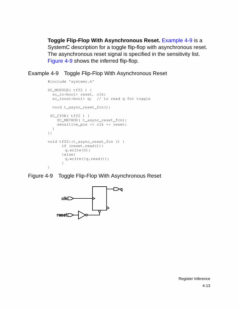
4-13
Register Inference
Toggle Flip-Flop With Asynchronous Reset. Example 4-9 is aSystemC description for a toggle flip-flop with asynchronous reset.The asynchronous reset signal is specified in the sensitivity list.Figure 4-9 shows the inferred flip-flop.
Example 4-9 Toggle Flip-Flop With Asynchronous Reset#include "systemc.h"
SC_MODULE( tff2 ) { sc_in<bool> reset, clk; sc_inout<bool> q; // to read q for toggle
void t_async_reset_fcn();
SC_CTOR( tff2 ) { SC_METHOD( t_async_reset_fcn); sensitive_pos << clk << reset; }};
void tff2::t_async_reset_fcn () { if (reset.read()){
q.write(0); }else{
q.write(!q.read()); }}
Figure 4-9 Toggle Flip-Flop With Asynchronous Reset

4-14
Chapter 4: RTL Coding Guidelines
Latch Inference
In simulation, a signal or a variable holds its value until that value isreassigned. A latch implements the ability to hold a state inhardware. SystemC Compiler supports inference of set/reset (SR)and delay (D) latches.
You can unintentionally infer latches from your SystemC code, whichcan add unnecessary hardware. SystemC Compiler infers a D latchwhen your description has an incomplete assignment in an if…elseor switch…case statement. To avoid creating a latch, specify allconditions in if…else and switch…case statements and assign allvariables in each branch.
Inferring a D Latch From an If Statement
An if statement infers a D latch when there is no else clause, asshown in Example 4-10. The SystemC code specifies a value foroutput out_q only when the clock has a logic 1 value, and it does notspecify a value when the clock has a logic 0 value. As a result, outputout_q becomes a latched value. Figure 4-10 shows the schematic ofthe inferred latch.
Example 4-10 D Latch Inference Using an if Statement#include "systemc.h"
SC_MODULE( d_latch1 ) { sc_in<bool> in_data; sc_in<bool> clock; sc_out<bool> out_q;
// Method process void d_latch_fcn () { if (clock.read()) {out_q.write(in_data.read());} }
// Constructor SC_CTOR( d_latch1 ) {

4-15
Register Inference
SC_METHOD( d_latch_fcn); sensitive << in_data << clock; }};
Figure 4-10 D Latch Inferred From an if Statement
Inferring an SR Latch. SR latches are difficult to test, so use themwith caution. If you use SR latches, verify that the inputs are hazardfree and do not generate glitches. During synthesis, SystemCCompiler does not ensure that the logic driving the inputs is hazardfree.
Example 4-11 is the SystemC code that implements the truth tablein Table 4-2 for an SR latch. Figure 4-11 shows the inferred SR latch.
Output y is unstable when both inputs are at a logic 0 value, so youneed to include a check in the SystemC code to detect this conditionduring simulation. SystemC Compiler does check for theseconditions.
Table 4-2 Truth Table for the SR Latch (NAND Type)
set reset Q
0 0 Not stable
0 1 1
1 0 0
1 1 Q

4-16
Chapter 4: RTL Coding Guidelines
Example 4-11 SR Latch/***sr_latch.cc***/
#include "systemc.h"
SC_MODULE( sr_latch ) { sc_in<bool> RESET, SET; sc_out<bool> Q;
void sr_latch_fcn () { if (RESET.read() == 0){ Q.write(0); }else if (SET.read() == 0){ Q.write(1); } }
SC_CTOR( sr_latch ) { SC_METHOD( sr_latch_fcn); sensitive << RESET << SET; }};
Figure 4-11 SR Latch
Avoiding Latch Inference. To avoid latch inference, assign a valueto a signal for all cases in a conditional statement. Example 4-12shows addition of an else clause to avoid the latch inferred by the ifstatement in Example 4-10, and Figure 4-12 shows the resultingschematic.

4-17
Register Inference
Example 4-12 Adding an Else Clause to Avoid Latch Inference#include "systemc.h"
SC_MODULE( d_latch1a ) { sc_in<bool> in_data; sc_in<bool> clock; sc_out<bool> out_q;
// Method process void d_latch_fcn () { if (clock.read()){ out_q.write(in_data.read()); }else{ out_q.write(false); } }
// Constructor SC_CTOR( d_latch1a ) { SC_METHOD( d_latch_fcn); sensitive << in_data << clock; }};
Figure 4-12 Avoiding Latch Inference by Adding Else Clause
You can also avoid latch inference by assigning a default value to theoutput port. Example 4-13 shows the setting of a default value toavoid the latch inferred by the if statement in Example 4-10, andFigure 4-13 shows the resulting schematic.

4-18
Chapter 4: RTL Coding Guidelines
Example 4-13 Setting a Default Value to Avoid Latch Inference#include "systemc.h"
SC_MODULE( d_latch1b ) { sc_in<bool> in_data; sc_in<bool> clock; sc_out<bool> out_q;
// Method process void d_latch_fcn () { out_q.write(1); // set a default if (clock.read()) {out_q.write(in_data.read());} }
// Constructor SC_CTOR( d_latch1b ) { SC_METHOD( d_latch_fcn); sensitive << in_data << clock; }};
Figure 4-13 Avoiding Latch Inference by Setting a Default Value
Inferring a Latch From a Switch Statement
Example 4-14 shows a switch statement that infers D latchesbecause it does not provide assignments to the out port for allpossible values of the in_i input. Figure 4-14 shows the inferredlatches.

4-19
Register Inference
Example 4-14 Latch Inference From a switch Statement#include "systemc.h"
SC_MODULE( d_latch2 ) { sc_in<unsigned char> in_i; sc_out<unsigned char> out;
// Method process void d_latch_fcn () { switch (in_i.read()) { case 0: out.write(0x01); break; case 1: out.write(0x02); break; case 2: out.write(0x04); break; case 3: out.write(0x10); break; case 4: out.write(0x20); break; case 5: out.write(0x40); break; } }
// Constructor SC_CTOR( d_latch2 ) { SC_METHOD( d_latch_fcn); sensitive (in_i); }};

4-20
Chapter 4: RTL Coding Guidelines
Figure 4-14 Latch Inference From a switch Statement

4-21
Register Inference
To avoid latch inference caused by the incomplete switch statementin Example 4-14, add a default case statement, as shown inExample 4-15. Figure 4-15 shows the resulting schematic.
Example 4-15 Avoiding Latch Inference From a switchStatement
#include "systemc.h"
SC_MODULE( d_latch2a ) { sc_in<unsigned char> in_i; sc_out<unsigned char> out;
// Method process void d_latch_fcn () { switch (in_i.read()) { case 0: out.write(0x01); break; case 1: out.write(0x02); break; case 2: out.write(0x04); break; case 3: out.write(0x10); break; case 4: out.write(0x20); break; case 5: out.write(0x40); break; default: out.write(0x01); } }
// Constructor SC_CTOR( d_latch2a ) { SC_METHOD( d_latch_fcn); sensitive (in_i); }};
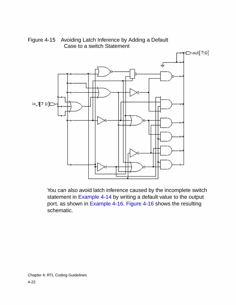
4-22
Chapter 4: RTL Coding Guidelines
Figure 4-15 Avoiding Latch Inference by Adding a DefaultCase to a switch Statement
You can also avoid latch inference caused by the incomplete switchstatement in Example 4-14 by writing a default value to the outputport, as shown in Example 4-16. Figure 4-16 shows the resultingschematic.

4-23
Register Inference
Example 4-16 Set a Default Value to Avoid Latch Inference From aswitch Statement
#include "systemc.h"
SC_MODULE( d_latch2b ) { sc_in<unsigned char> in_i; sc_out<unsigned char> out;
// Method process void d_latch_fcn () { out.write(1); // Set default value switch (in_i.read()) { case 0: out.write(0x01); break; case 1: out.write(0x02); break; case 2: out.write(0x04); break; case 3: out.write(0x10); break; case 4: out.write(0x20); break; case 5: out.write(0x40); break; } }
// Constructor SC_CTOR( d_latch2b ) { SC_METHOD( d_latch_fcn); sensitive (in_i); }};

4-24
Chapter 4: RTL Coding Guidelines
Figure 4-16 Avoiding Latch Inference by Setting a Default CaseBefore a switch Statement
Priority Encoding
Switch…case and if…else conditional statements are priority-encoded in simulation. Priority-encoded hardware is rarely needed,and it can add unnecessary gates and time to the synthesizeddesign.

4-25
Register Inference
SystemC Compiler defaults to priority-encoded logic for a switchstatement when
• You do not define all the cases in a switch statement
• All the cases are not mutually exclusive
In addition to defining a default case (Example 4-15 on page 4-21)and setting a default value (Example 4-16 on page 4-23), you caninstruct SystemC Compiler that other cases are not necessary for aswitch statement by adding the full_case compiler directive inyour code. Example 4-17 uses the full_case directive, andFigure 4-17 shows the resulting schematic.
Example 4-17 Using the full_case Compiler Directive With aswitch Statement
#include "systemc.h"
SC_MODULE( d_latch2c ) { sc_in<unsigned char> in_i; sc_out<unsigned char> out;
// Method process void d_latch_fcn () { switch (in_i.read()) { // synopsys full_case case 0: out.write(0x01); break; case 1: out.write(0x02); break; case 2: out.write(0x04); break; case 3: out.write(0x10); break; case 4: out.write(0x20); break; case 5: out.write(0x40); break; } }
// Constructor SC_CTOR( d_latch2c ) { SC_METHOD( d_latch_fcn); sensitive (in_i); }};

4-26
Chapter 4: RTL Coding Guidelines
Figure 4-17 Using the full_case Compiler Directive With aswitch Statement
Active-Low Set and Reset
To instruct SystemC Compiler to implement all the signals in a groupas active-low, add a check to the SystemC code to ensure that thegroup of signals has only one active-low signal at a given time.SystemC Compiler does not produce any logic to check thisassertion.
Example 4-18 shows a latch with an active-low set and reset.Figure 4-18 shows the resulting schematic.

4-27
Register Inference
Example 4-18 Latch With Active-Low Set and Reset#include "systemc.h"
SC_MODULE( d_latch6a ) { sc_in<bool> in_data, set, reset; sc_in<bool> clock; sc_out<bool> out_q;
void d_latch_fcn (){ infer_latch: { if (reset.read() == 0){ out_q.write(0); }else if (set.read() == 0){ out_q.write(1); }else if (clock.read()){ out_q.write(in_data.read()); } } } // Constructor SC_CTOR( d_latch6a ) { SC_METHOD( d_latch_fcn); sensitive << in_data << clock << set << reset; }};
Figure 4-18 Latch With Active-Low Set and Reset
Active-High Set and Reset
To instruct SystemC Compiler to implement all the signals in a groupas active-high, add a check to the SystemC code to ensure that thegroup of signals has only one active-high signal at a given time.SystemC Compiler does not produce any logic to check thisassertion.

4-28
Chapter 4: RTL Coding Guidelines
Example 4-19 shows a latch with the set and reset specified asactive-high. Figure 4-19 shows the resulting schematic.
Example 4-19 Latch With Active-High Set and Reset#include "systemc.h"
SC_MODULE( d_latch7a ) { sc_in<bool> in_data, set, reset; sc_in<bool> clock; sc_out<bool> out_q;
void d_latch_fcn (){ infer_latch: { if (reset.read()){ out_q.write(0); }else if (set.read()){ out_q.write(1); }else if (clock.read()){ out_q.write(in_data.read()); } } } // Constructor SC_CTOR( d_latch7a ) { SC_METHOD( d_latch_fcn); sensitive << in_data << clock << set << reset; }};
Figure 4-19 Latch With Active-High Set and Reset

4-29
Register Inference
D Latch With an Asynchronous Set and Reset
Example 4-20 is a SystemC description for a D latch with anactive-low asynchronous set and reset. Figure 4-20 shows theinferred latch.
Example 4-20 D Latch With Asynchronous Set and Reset#include "systemc.h"
SC_MODULE( d_latch6 ) { sc_in<bool> in_data, set, reset; sc_in<bool> clock; sc_out<bool> out_q;
void d_latch_fcn (){ if (reset.read() == 0){ out_q.write(0); }else if (set.read() == 0){ out_q.write(1); }else if (clock.read()){ out_q.write(in_data.read()); } } // Constructor SC_CTOR( d_latch6 ) { SC_METHOD( d_latch_fcn); sensitive << in_data << clock << set << reset; }};
Figure 4-20 Latch With Asynchronous Set and Reset

4-30
Chapter 4: RTL Coding Guidelines
D Latch With an Asynchronous Set
Example 4-21 is a SystemC description for a D latch with anasynchronous set. Figure 4-21 shows the inferred latch.
Example 4-21 D Latch With Asynchronous Set#include "systemc.h"
SC_MODULE( d_latch4 ) { sc_in<bool> in_data, set; sc_in<bool> clock; sc_out<bool> out_q;
void d_latch_fcn () { if (set.read() == 0){ out_q.write( 1 ); }else if (clock.read()){ out_q.write(in_data.read()); } }
// Constructor SC_CTOR( d_latch4 ) { SC_METHOD( d_latch_fcn); sensitive << in_data << clock << set; }};
Figure 4-21 Latch With Asynchronous Set
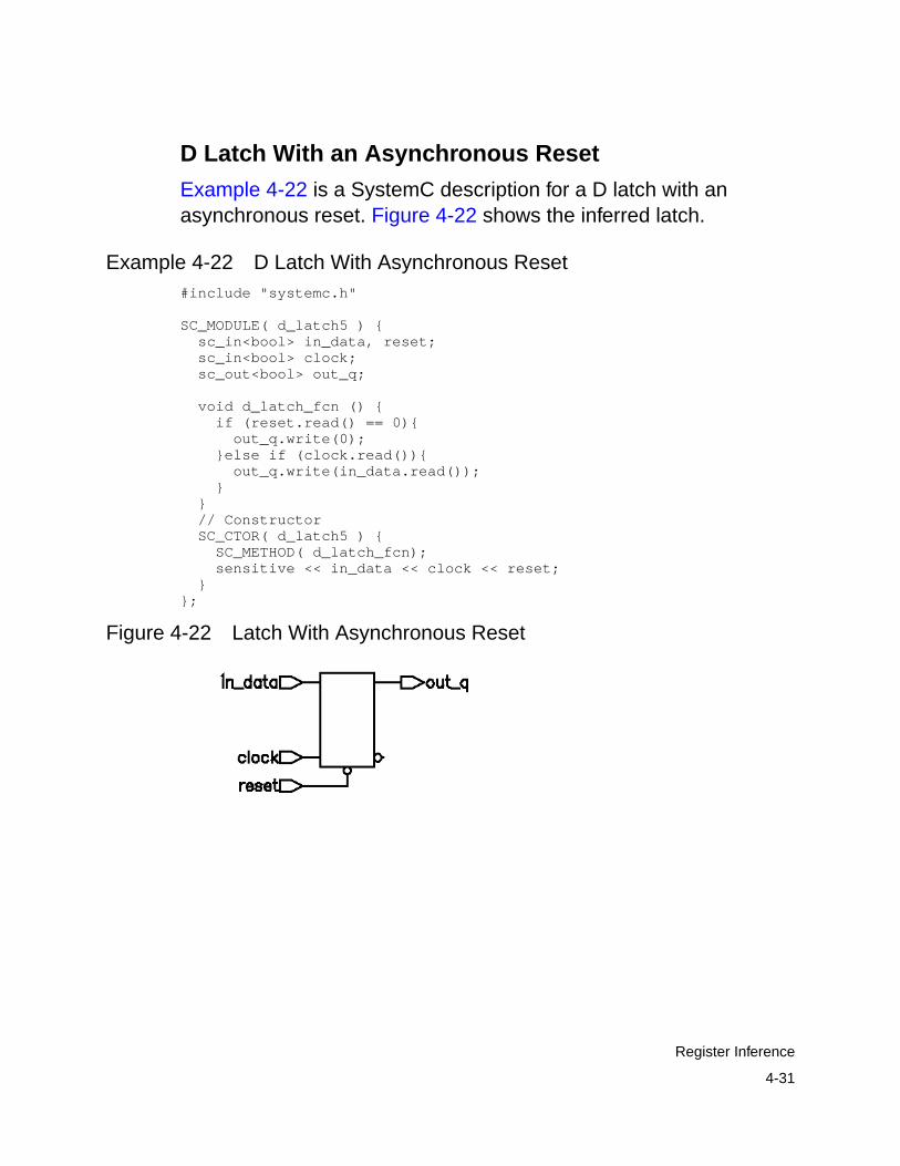
4-31
Register Inference
D Latch With an Asynchronous Reset
Example 4-22 is a SystemC description for a D latch with anasynchronous reset. Figure 4-22 shows the inferred latch.
Example 4-22 D Latch With Asynchronous Reset#include "systemc.h"
SC_MODULE( d_latch5 ) { sc_in<bool> in_data, reset; sc_in<bool> clock; sc_out<bool> out_q;
void d_latch_fcn () { if (reset.read() == 0){ out_q.write(0); }else if (clock.read()){ out_q.write(in_data.read()); } } // Constructor SC_CTOR( d_latch5 ) { SC_METHOD( d_latch_fcn); sensitive << in_data << clock << reset; }};
Figure 4-22 Latch With Asynchronous Reset

4-32
Chapter 4: RTL Coding Guidelines
Understanding the Limitations of Register Inference
SystemC Compiler cannot infer the following components:
• Flip-flops and latches with three-state outputs
• Flip-flops with bidirectional pins
• Flip-flips with multiple clock inputs
• Multiport latches
You can instantiate these components in your SystemC description.SystemC Compiler interprets these flip-flops and latches as blackboxes.
Instantiating a Component as a Black Box
To instantiate a flip-flop or a latch as a black box in your SystemCRTL netlist, create a dummy SystemC module with the same modulename and port names as those of the cell in the technology librarythat you want to instantiate. The module and port names arecase-sensitive and must exactly match the cell names. You do notneed to describe the module’s function, because Design Compilerreplaces it with the actual library cell.
Example 4-23 shows a dummy module for the or2c1 cell from thetc6a_cbacore sample technology library. An instance of the or2c1module named my_gate is created in the gate module.

4-33
Register Inference
Example 4-23 Instantiating a Register That Cannot Be Inferred/****gate.h****/
/***************************************** * This example shows how to instantiate * an or2c1 gate from the tc6a_cbacore * library in a SystemC RTL netlist. *****************************************/#include "systemc.h"
SC_MODULE(or2c1) { sc_in<bool> A, B; sc_out<bool> Y;
SC_CTOR(or2c1) {}};
SC_MODULE(gate) { sc_in<bool> clk, reset; sc_in<sc_uint<8> > data; sc_out<bool> match;
sc_signal<bool> a_match, b_match;
/* * RTL processes */ void match_a(); void match_b();
/* * Pointer for block allocation */ or2c1 *my_gate;
SC_CTOR(gate) { /* * Instantiate and hook up the gate */ my_gate = new or2c1("my_gate"); my_gate->A(a_match); my_gate->B(b_match); my_gate->Y(match);
SC_METHOD(match_a); sensitive_pos << clk; sensitive_neg << reset;
SC_METHOD(match_b); sensitive_pos << clk; sensitive_neg << reset;

4-34
Chapter 4: RTL Coding Guidelines
}};
/****gate.cc****/#include "gate.h"
void gate::match_a() { if (reset.read() == 0) { a_match = 0; } else { if (data.read() == 3) { a_match = 1; } else { a_match = 0; } }}
void gate::match_b() { if (reset.read() == 0) { b_match = 0; } else { if (data.read() == 7) { b_match = 1; } else { b_match = 0; } }}
To perform RTL synthesis and instantiate the or2c1 cell,
1. Elaborate the gate module that contains the dummy or2c1module.
dc_shell> compile_systemc -rtl -format db gate.cc
2. Remove the dummy module.
dc_shell> remove_design or2c1
3. Set the current design to be the gate module.
dc_shell> current_design gate
4. Remove the current links, and create new links for the design.This links the or2c1 cell from the technology library.
4-35
Multibit Inference
dc_shell> link
5. Instruct Design Compiler not to touch the my_gate instantiationof the or2c1 cell in the design.
dc_shell> set_dont_touch find(cell, my_gate)
6. Compile the design to gates.
dc_shell> compile
Multibit Inference
A multibit component (MBC), such as a 16-bit register, reduces thearea and power in a design. The primary benefit of MBCs is to createa more uniform structure for layout during place and route.
Multibit inference allows you to map registers, multiplexers, andthree-state cells to regularly structured logic or multibit library cells.Multibit library cells (macro cells, such as 16-bit banked flip-flops)have these advantages:
• Smaller area and delay, due to shared transistors (as in select orset/reset logic) and optimized transistor-level layout. Withsingle-bit components, the select or set/reset logic is repeated ineach single-bit component.
• Reduced clock skew in sequential gates, because the clockpaths are balanced internally in the hard macro implementing theMBC.
• Lower power consumption by the clock in sequential bankedcomponents, due to reduced capacitance driven by the clock net.
• Better performance, due to the optimized layout within the MBC.

4-36
Chapter 4: RTL Coding Guidelines
• Improved regular layout of the datapath.
To direct SystemC Compiler to infer multibit components,
• Add the infer_multibit or dont_infer_ multibitcompiler directive (see “Multibit Inference Compiler Directives”on page A-3) to individual ports or signals in the SystemCdescription.
• Or define the dc_shell hdlin_infer_multibit variable,which specifies that multibit inference is allowed for the entiredesign. The allowed values for hdlin_infer_multibit aredefault_all, default_none, and never. See thehdlin_infer_multibit man page for additional information.
Inferring Multibit
Example 4-24 shows inference of a 2-bit multiplexer, resulting in theschematic in Figure 4-23.
Example 4-24 Inferring a 2-Bit 4-to-1 Multiplexer#include "systemc.h"
SC_MODULE( infer_multibit ) {
sc_in<sc_uint<2> > a; sc_in<sc_int<2> > w; sc_in<sc_int<2> > x; sc_in<sc_int<2> > y; sc_in<sc_int<2> > z;
sc_out<sc_int<2> > b1; // synopsys infer_multibit "b1"
void f1 ();
SC_CTOR( infer_multibit ) { SC_METHOD( f1); sensitive << a << w << x << y << z; }};
void infer_multibit:: f1 ()
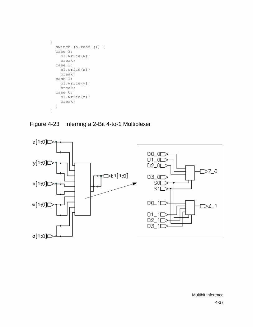
4-37
Multibit Inference
{ switch (a.read ()) { case 3: b1.write(w); break; case 2: b1.write(x); break; case 1: b1.write(y); break; case 0: b1.write(z); break; }}
Figure 4-23 Inferring a 2-Bit 4-to-1 Multiplexer
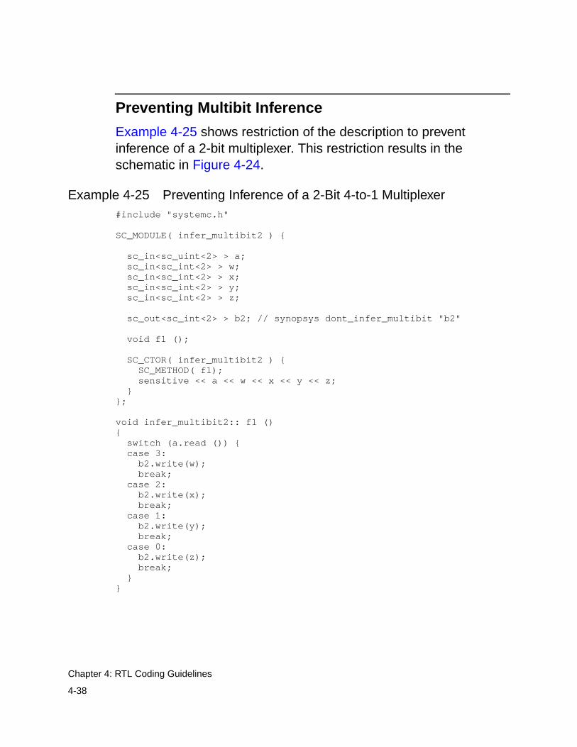
4-38
Chapter 4: RTL Coding Guidelines
Preventing Multibit Inference
Example 4-25 shows restriction of the description to preventinference of a 2-bit multiplexer. This restriction results in theschematic in Figure 4-24.
Example 4-25 Preventing Inference of a 2-Bit 4-to-1 Multiplexer#include "systemc.h"
SC_MODULE( infer_multibit2 ) {
sc_in<sc_uint<2> > a; sc_in<sc_int<2> > w; sc_in<sc_int<2> > x; sc_in<sc_int<2> > y; sc_in<sc_int<2> > z;
sc_out<sc_int<2> > b2; // synopsys dont_infer_multibit "b2"
void f1 ();
SC_CTOR( infer_multibit2 ) { SC_METHOD( f1); sensitive << a << w << x << y << z; }};
void infer_multibit2:: f1 (){ switch (a.read ()) { case 3: b2.write(w); break; case 2: b2.write(x); break; case 1: b2.write(y); break; case 0: b2.write(z); break; }}

4-39
Multiplexer Inference
Figure 4-24 Preventing Inference of a 2-Bit 4-to-1 Multiplexer
Multiplexer Inference
SystemC Compiler can infer a generic multiplexer cell (MUX_OP)from switch statements and if-then-else statements in your SystemCdescription. SystemC Compiler maps inferred MUX_OPs tomultiplexer cells in the target technology library.
The size of the inferred MUX_OP depends on the number of uniquecases in the switch statement. If you want to use the multiplexerinference feature, the target technology library must contain at leasta 2-to-1 multiplexer.
MUX_OPs are hierarchical cells similar to Synopsys DesignWarecomponents. SystemC Compiler passes the multiplexer inferenceinformation to Design Compiler, and Design Compiler determinesthe MUX_OP implementation during logic synthesis, based on the

4-40
Chapter 4: RTL Coding Guidelines
design constraints. For information about how Design Compilermaps MUX_OPs to multiplexers in the target technology library, seethe Design Compiler Reference Manual: Optimization and TimingAnalysis.
Inferring Multiplexers From a Block of Code
Use the infer_mux compiler directive to instruct SystemCCompiler to infer MUX_OPs for all switch statements inside a blockof code. In Example 4-26, the infer_mux compiler directive isattached to the code block labeled tt, which contains two switchstatements. The code block can contain any number of switchstatements.
SystemC Compiler infers a MUX_OP for each case in the switchstatement. The first switch statement has four unique cases andinfers a 4-to-1 MUX_OP. The second switch statement has twounique cases and infers a 2-to-1 MUX_OP. Figure 4-25 shows theinferred multiplexers.
Example 4-26 Multiplexer Inference From a Block of Code#include "systemc.h"
SC_MODULE( infer_mux_blk ) { sc_in<sc_uint<2> > a; sc_in<sc_uint<1> > b; sc_in<sc_int<2> > w, x, y, z; sc_out<sc_int<2> > b2, b3;
void f2 ();
SC_CTOR( infer_mux_blk ) {
SC_METHOD( f2); sensitive << a <<b << w << x << y << z; }};
// infer mux for all switch statements in block ’tt’void infer_mux_blk:: f2 ()

4-41
Multiplexer Inference
{ // synopsys infer_mux "tt" tt: { switch (a.read ()) { case 3: b2.write(w); break; case 2: b2.write(x); break; case 1: b2.write(y); break; case 0: b2.write(z); break; } switch (b.read ()) { case 1: b3.write(y); break; case 0: b3.write(z); break; } }}
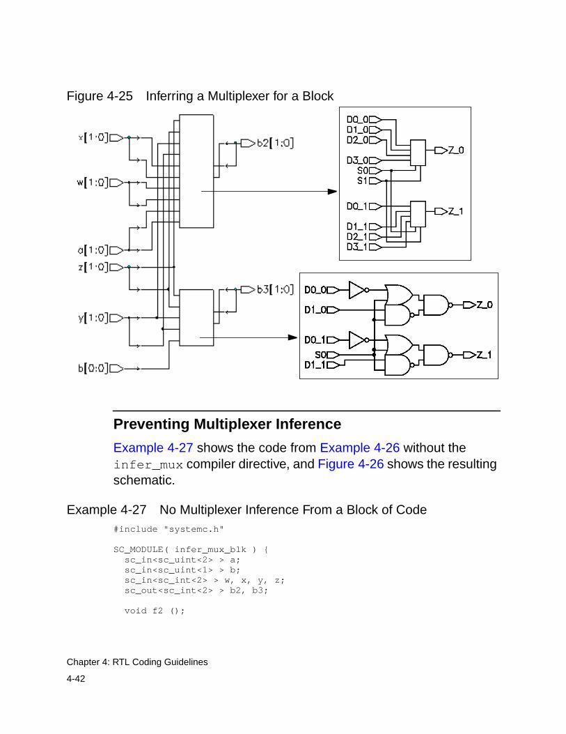
4-42
Chapter 4: RTL Coding Guidelines
Figure 4-25 Inferring a Multiplexer for a Block
Preventing Multiplexer Inference
Example 4-27 shows the code from Example 4-26 without theinfer_mux compiler directive, and Figure 4-26 shows the resultingschematic.
Example 4-27 No Multiplexer Inference From a Block of Code#include "systemc.h"
SC_MODULE( infer_mux_blk ) { sc_in<sc_uint<2> > a; sc_in<sc_uint<1> > b; sc_in<sc_int<2> > w, x, y, z; sc_out<sc_int<2> > b2, b3;
void f2 ();

4-43
Multiplexer Inference
SC_CTOR( infer_mux_blk ) {
SC_METHOD( f2); sensitive << a <<b << w << x << y << z; }};
/* Do not use the infer mux for all switch statements in block ’tt’ */
void infer_mux_blk:: f2 (){ tt: { switch (a.read ()) { case 3: b2.write(w); break; case 2: b2.write(x); break; case 1: b2.write(y); break; case 0: b2.write(z); break; } switch (b.read ()) { case 1: b3.write(y); break; case 0: b3.write(z); break; } }}
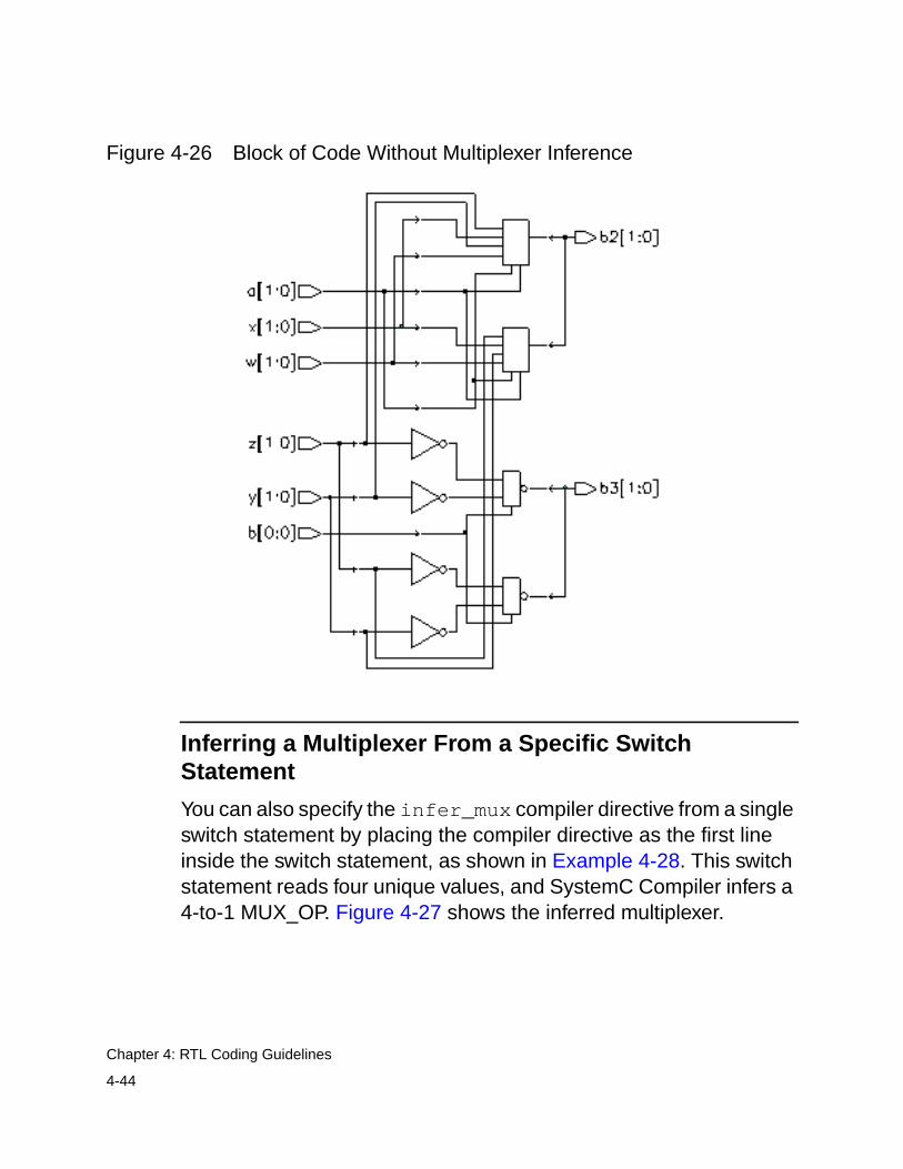
4-44
Chapter 4: RTL Coding Guidelines
Figure 4-26 Block of Code Without Multiplexer Inference
Inferring a Multiplexer From a Specific SwitchStatement
You can also specify the infer_mux compiler directive from a singleswitch statement by placing the compiler directive as the first lineinside the switch statement, as shown in Example 4-28. This switchstatement reads four unique values, and SystemC Compiler infers a4-to-1 MUX_OP. Figure 4-27 shows the inferred multiplexer.

4-45
Multiplexer Inference
Example 4-28 Multiplexer Inference From a Specific switchStatement
#include "systemc.h"
SC_MODULE( infer_mux_blk3 ) { sc_in<sc_uint<2> > a; sc_in<sc_uint<1> > b; sc_in<sc_int<2> > w, x, y, z; sc_out<sc_int<2> > b2, b3;
void f2 ();
SC_CTOR( infer_mux_blk3 ) {
SC_METHOD( f2); sensitive << a <<b << w << x << y << z; }};
/* Infer mux for only the first switch statement in block ’tt’ */void infer_mux_blk3:: f2 (){ tt: { switch (a.read ()) { //synopsys infer_mux case 3: b2.write(w); break; case 2: b2.write(x); break; case 1: b2.write(y); break; case 0: b2.write(z); break; } switch (b.read ()) { case 1: b3.write(y); break; case 0: b3.write(z); break; } }}

4-46
Chapter 4: RTL Coding Guidelines
Figure 4-27 Inferring a Multiplexer From a Specific switchStatement
Understanding the Limitations of Multiplexer Inference
SystemC Compiler does not infer MUX_OPs for
• if...else statements
• switch statements in while loops

4-47
Three-State Inference
SystemC Compiler infers MUX_OPs for incompletely specifiedswitch statements, but the resulting logic might not be optimal.SystemC Compiler considers the following types of switchstatements incompletely specified:
• A switch statement that has a missing case statement branch
• A switch statement that contains an if statement
• A switch statement that contains other switch statements
Three-State Inference
A three-state driver is inferred when you assign the value Z to avariable. The value Z represents the high-impedance state. You canassign high-impedance values to single-bit or bused variables. Theassignment must occur in a conditional statement (if or switch) orwith the conditional operator (?:). Note that only the sc_logic andsc_lv data types support the value Z.
Simple Three-State Inference
Example 4-29 is a SystemC description for a simple three-statedriver. Figure 4-28 shows the schematic the code generates.
Example 4-29 Three-State Buffer Inference From a Block ofCode
// simple three-state buffer inference#include "systemc.h"SC_MODULE( tristate_ex1 ) { sc_in<bool> control; sc_in<sc_logic> data; sc_out<sc_logic> ts_out;
// Method for three-state driver void tristate_fcn () {
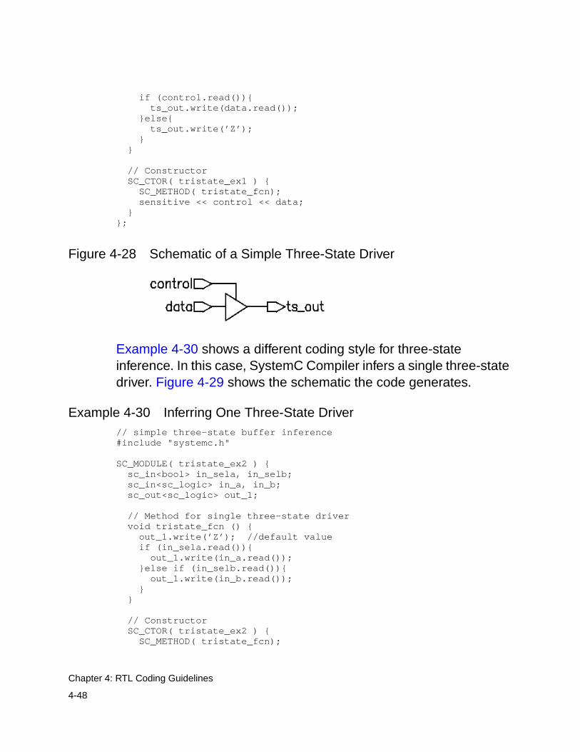
4-48
Chapter 4: RTL Coding Guidelines
if (control.read()){ ts_out.write(data.read()); }else{ ts_out.write(’Z’); } }
// Constructor SC_CTOR( tristate_ex1 ) { SC_METHOD( tristate_fcn); sensitive << control << data; }};
Figure 4-28 Schematic of a Simple Three-State Driver
Example 4-30 shows a different coding style for three-stateinference. In this case, SystemC Compiler infers a single three-statedriver. Figure 4-29 shows the schematic the code generates.
Example 4-30 Inferring One Three-State Driver// simple three-state buffer inference#include "systemc.h"
SC_MODULE( tristate_ex2 ) { sc_in<bool> in_sela, in_selb; sc_in<sc_logic> in_a, in_b; sc_out<sc_logic> out_1;
// Method for single three-state driver void tristate_fcn () { out_1.write(’Z’); //default value if (in_sela.read()){ out_1.write(in_a.read()); }else if (in_selb.read()){ out_1.write(in_b.read()); } }
// Constructor SC_CTOR( tristate_ex2 ) { SC_METHOD( tristate_fcn);
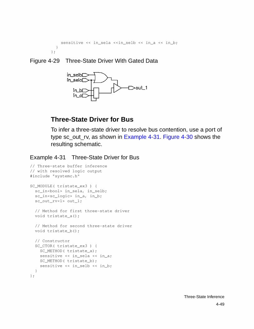
4-49
Three-State Inference
sensitive << in_sela <<in_selb << in_a << in_b; }};
Figure 4-29 Three-State Driver With Gated Data
Three-State Driver for Bus
To infer a three-state driver to resolve bus contention, use a port oftype sc_out_rv, as shown in Example 4-31. Figure 4-30 shows theresulting schematic.
Example 4-31 Three-State Driver for Bus// Three-state buffer inference// with resolved logic output#include "systemc.h"
SC_MODULE( tristate_ex3 ) { sc_in<bool> in_sela, in_selb; sc_in<sc_logic> in_a, in_b; sc_out_rv<1> out_1;
// Method for first three-state driver void tristate_a();
// Method for second three-state driver void tristate_b();
// Constructor SC_CTOR( tristate_ex3 ) { SC_METHOD( tristate_a); sensitive << in_sela << in_a; SC_METHOD( tristate_b); sensitive << in_selb << in_b; }};

4-50
Chapter 4: RTL Coding Guidelines
void tristate_ex3::tristate_a() { if (in_sela.read()){ out_1.write(in_a.read()); }else{ out_1.write("Z"); }}
void tristate_ex3::tristate_b() { if (in_selb.read()){ out_1.write(in_b.read()); }else{ out_1.write("Z"); }}
Figure 4-30 Three-State Bus Driver Schematic
Registered Three-State Drivers
When a variable is registered in the same process in which it isinferred as three-state, SystemC Compiler also registers the enablepin of the three-state gate. Example 4-32 is an example of this typeof code. Figure 4-31 shows the schematic generated by the code.
Example 4-32 Three-State Driver With Registered Enable// simple three-state buffer inference#include "systemc.h"
SC_MODULE( tristate_ex4 ) { sc_in<bool> control; sc_in<sc_logic> data; sc_out<sc_logic> ts_out;

4-51
Three-State Inference
sc_in_clk clk;
// Method for three-state driver void tristate_fcn () { if (control.read()){ ts_out.write(data.read()); }else{ ts_out.write(’Z’); } }
// Constructor SC_CTOR( tristate_ex4 ) { SC_METHOD( tristate_fcn); sensitive_pos << clk; // note inferred seq logic }};
Figure 4-31 Three-State Driver With Registered Enable
To avoid registering the enable pin, separate the three-state driverinference from the sequential logic inference, using twoSC_METHOD processes. Example 4-33 uses two methods toinstantiate a three-state gate, with a flip-flop only on the input. Notethat the sc_signal temp is used to communicate between the twoSC_METHOD processes. Figure 4-32 shows the schematic thecode generates.

4-52
Chapter 4: RTL Coding Guidelines
Example 4-33 Three-State Driver Without Registered Enable// simple three-state buffer inference#include "systemc.h"
SC_MODULE( tristate_ex5 ) { sc_in<bool> control; sc_in<sc_logic> data; sc_out<sc_logic> ts_out; sc_in_clk clk;
sc_signal<sc_logic> temp;
// Method for three-state driver void tristate_fcn () { if (control.read()){ ts_out.write(temp); }else{ ts_out.write(’Z’); } }
// Method for sequential logic void flop () { temp = data.read(); }
// Constructor SC_CTOR( tristate_ex5 ) { SC_METHOD( tristate_fcn); sensitive << control << temp ; SC_METHOD( flop ); sensitive_pos << clk; }};
Figure 4-32 Three-State Driver Without Registered Enable

4-53
Loops
Understanding the Limitations of Three-State Inference
The value of Z is valid only for the sc_logic and sc_lv data types. Youcan use the Z value in the following ways:
• Variable assignment
• Function call argument
• Return value
You cannot use the Z value in an expression, except for comparisonwith Z. Be careful when using expressions that compare with the Zvalue. SystemC Compiler always evaluates these expressions tofalse, and the pre-synthesis and post-synthesis simulation resultsmight differ. For this reason, SystemC Compiler issues a warningwhen it synthesizes such comparisons. The following exampleshows incorrect use of the Z value in an expression:
OUT_VAL = (’Z’ && IN_VAL);
The following example shows correct use of the Z value:
IN_VAL = ’Z’;
Loops
SystemC Compiler supports for loops, while loops, and do-whileloops for synthesis. For RTL synthesis, SystemC Compiler keeps allloops rolled, but they are automatically unrolled by Design Compiler.Therefore, all loops must be unrollable.
4-54
Chapter 4: RTL Coding Guidelines
Loop Unrolling Criteria
To make a loop unrollable, adhere to the following criteria for creatingloops:
• A loop index must be an integer type. Valid types are char, short,int, long, sc_int, sc_bigint, and the unsigned version of thesetypes.
• The loop index initial value must resolve to a constant at compiletime.
• The loop index initial assignment cannot be in a conditionalbranch that may or may not be executed.
• The valid loop index operations are add, subtract, increment, anddecrement.
• The valid loop condition test relational operators are <, <=, >, >=,and !=. The equality operator == is not useful for a loop conditiontest and is not supported for synthesis.
• The loop condition test limit must be a constant value or anexpression that resolves to a constant at compile time.
• Loops cannot contain switch statements that have a continuestatement.
• The loop condition cannot be null or empty.
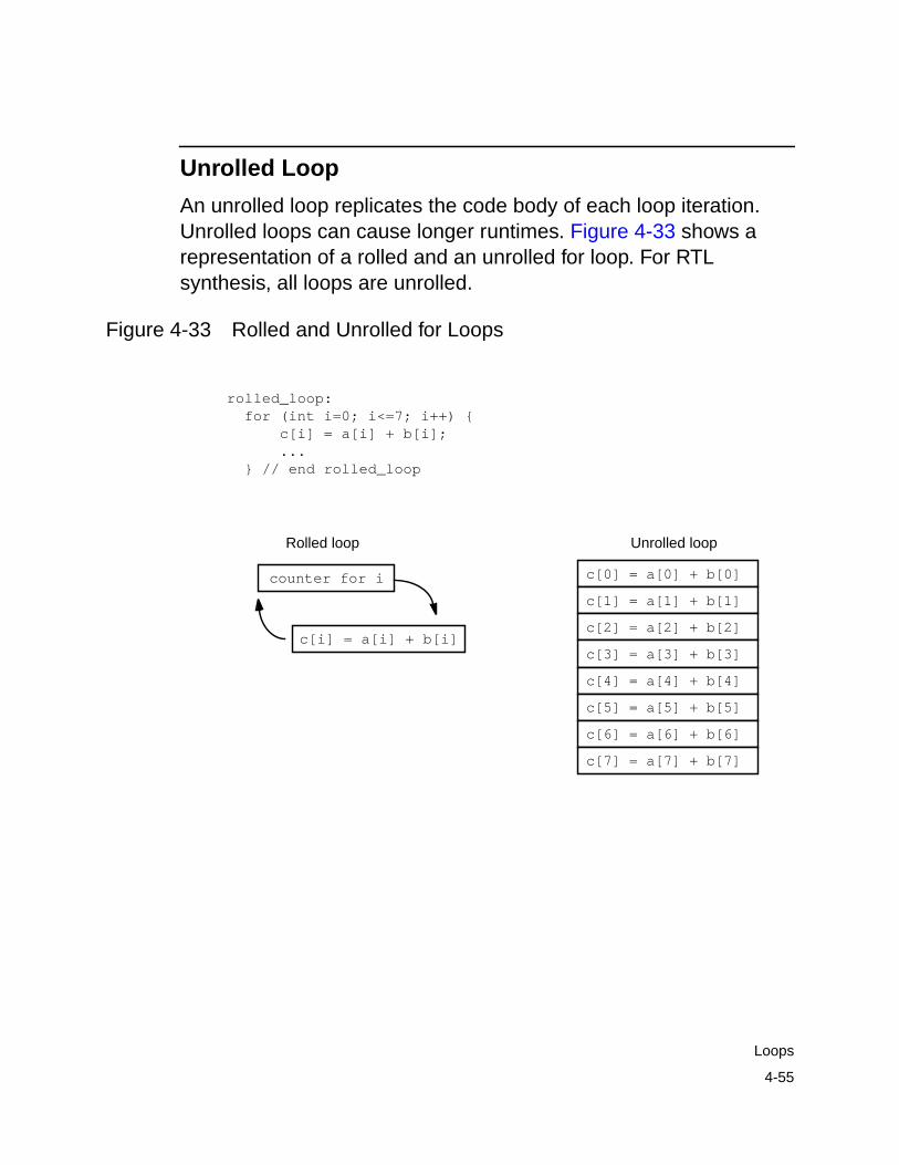
4-55
Loops
Unrolled Loop
An unrolled loop replicates the code body of each loop iteration.Unrolled loops can cause longer runtimes. Figure 4-33 shows arepresentation of a rolled and an unrolled for loop. For RTLsynthesis, all loops are unrolled.
Figure 4-33 Rolled and Unrolled for Loops
rolled_loop: for (int i=0; i<=7; i++) { c[i] = a[i] + b[i]; ... } // end rolled_loop
c[0] = a[0] + b[0]
c[1] = a[1] + b[1]
c[2] = a[2] + b[2]
c[3] = a[3] + b[3]
c[4] = a[4] + b[4]
c[5] = a[5] + b[5]
c[6] = a[6] + b[6]
c[7] = a[7] + b[7]
c[i] = a[i] + b[i]
counter for i
Rolled loop Unrolled loop
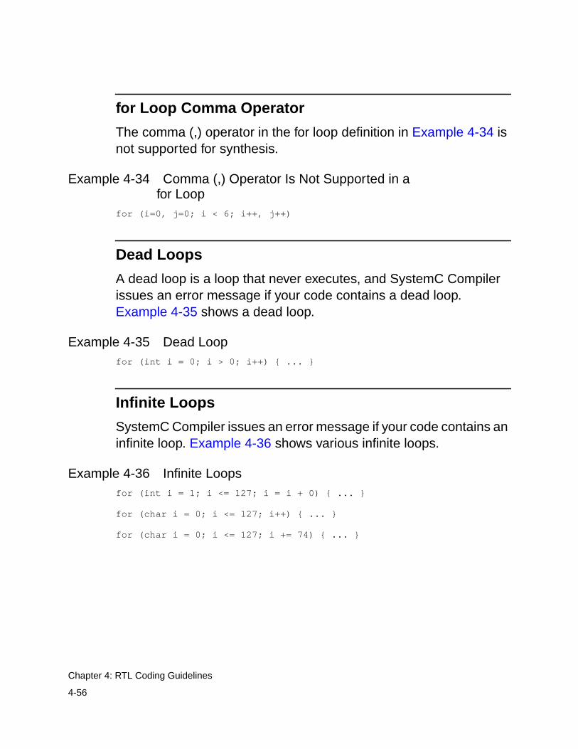
4-56
Chapter 4: RTL Coding Guidelines
for Loop Comma Operator
The comma (,) operator in the for loop definition in Example 4-34 isnot supported for synthesis.
Example 4-34 Comma (,) Operator Is Not Supported in afor Loop
for (i=0, j=0; i < 6; i++, j++)
Dead Loops
A dead loop is a loop that never executes, and SystemC Compilerissues an error message if your code contains a dead loop.Example 4-35 shows a dead loop.
Example 4-35 Dead Loopfor (int i = 0; i > 0; i++) { ... }
Infinite Loops
SystemC Compiler issues an error message if your code contains aninfinite loop. Example 4-36 shows various infinite loops.
Example 4-36 Infinite Loopsfor (int i = 1; i <= 127; i = i + 0) { ... }
for (char i = 0; i <= 127; i++) { ... }
for (char i = 0; i <= 127; i += 74) { ... }

4-57
State Machines
State Machines
Explicitly describe state machines for RTL synthesis. Figure 4-34shows a Mealy state machine structure.
Figure 4-34 Mealy State Machine
The diagram in Figure 4-34 has one sequential element—the statevector—and two combinational elements, the output logic and thenext-state logic. Although the output logic and the next-state logicare separate in this diagram, you can merge them into one logicblock in which gates can be shared for a smaller design area.
The output logic is always a function of the current state (statevector) and optionally a function of the inputs. If inputs are includedin the output logic, the state machine is a Mealy state machine. Ifinputs are not included, the state machine is a Moore state machine.
The next-state logic is always a function of the current state (statevector) and optionally a function of the inputs.
Inputs Outputs
Outputlogic
State
vectorclk
Next-statelogic

4-58
Chapter 4: RTL Coding Guidelines
The common implementations of state machines are
• An SC_METHOD process for updating the state vector and asingle common SC_METHOD process for both the output andthe next-state logic
• An SC_METHOD process for the state vector, an SC_METHODprocess for the output logic, and a separate SC_METHODprocess for the next-state logic
• A Moore machine with a single process for computing andupdating the next-state vector and outputs
Figure 4-35 shows a state diagram that represents a state machine,where a and b are outputs.
Figure 4-35 Finite State Machine State Diagram
S1
S2
input1==0
input1==1
input2==0 input2==1
S0
b = 0a = 0/1
b = 1a = 0
b = 0a = 0

4-59
State Machines
State Machine With a Common Computation Process
Example 4-37 shows the state machine represented in Figure 4-35with a common SC_METHOD process for computing the output andnext-state logic.
Example 4-37 State Machine With Common ComputationProcess
/**ex_fsm_a.h**/SC_MODULE(ex_fsm_a){
sc_in_clk clk; sc_in<bool> rst, input1, input2; sc_out<bool> a, b;
sc_signal<state_t> state, next_state;
void ns_logic(); void update_state();
SC_CTOR(ex_fsm_a){ SC_METHOD(update_state);
sensitive_pos << clk; SC_METHOD(ns_logic); sensitive << state << input1 << input2; } };
/**ex_fsm_a.cpp**/#include "systemc.h"#include "fsm_types.h"#include "ex_fsm_a.h"
void ex_fsm_a::update_state() { if (rst.read() == true){ state = S0; }else{ state = next_state; }}
void ex_fsm_a::ns_logic() {// Determine next state switch(state) { case S0: b.write(0); if (input1.read() || input2.read()){
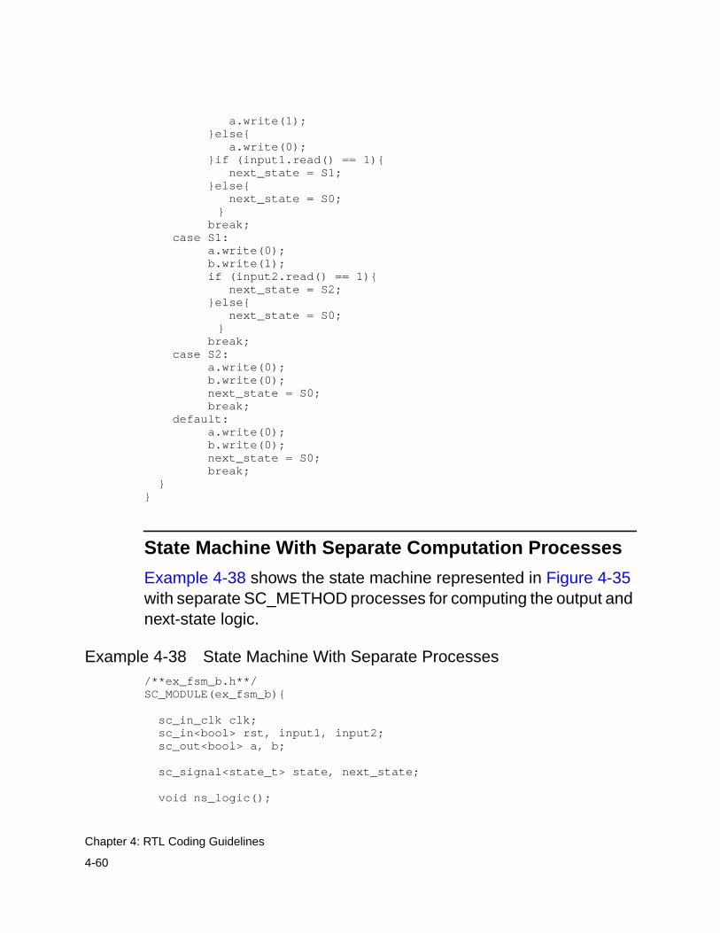
4-60
Chapter 4: RTL Coding Guidelines
a.write(1); }else{ a.write(0); }if (input1.read() == 1){ next_state = S1; }else{ next_state = S0;
} break; case S1: a.write(0); b.write(1); if (input2.read() == 1){ next_state = S2; }else{ next_state = S0;
} break; case S2: a.write(0); b.write(0); next_state = S0; break; default: a.write(0); b.write(0); next_state = S0; break; }}
State Machine With Separate Computation Processes
Example 4-38 shows the state machine represented in Figure 4-35with separate SC_METHOD processes for computing the output andnext-state logic.
Example 4-38 State Machine With Separate Processes/**ex_fsm_b.h**/SC_MODULE(ex_fsm_b){
sc_in_clk clk; sc_in<bool> rst, input1, input2; sc_out<bool> a, b;
sc_signal<state_t> state, next_state;
void ns_logic();

4-61
State Machines
void output_logic(); void update_state();
SC_CTOR(ex_fsm_b){ SC_METHOD(update_state); sensitive_pos << clk; SC_METHOD(ns_logic); sensitive << state << input1 << input2; SC_METHOD(output_logic); sensitive << state << input1 << input2; }};
/**ex_fsm_b.cpp**/#include "systemc.h"#include "fsm_types.h"#include "ex_fsm_b.h"
void ex_fsm_b::update_state() { if (rst.read() == true){ state = S0; }else{ state = next_state; }}
void ex_fsm_b::ns_logic() {
// Determine next state switch(state) { case S0: if (input1.read()) next_state = S1; else next_state = S0; break; case S1: if (input2.read()) next_state = S2; else next_state = S0; break; case S2: next_state = S0; break; default: next_state = S0; break; }}
void ex_fsm_b::output_logic(){// determine outputs

4-62
Chapter 4: RTL Coding Guidelines
a.write(state == S0 && (input1.read() || input2.read() ) ); b.write(state == S1);}
Moore State Machine
Example 4-39 shows a Moore state machine with a singleSC_METHOD process for computing and updating the output andnext-state logic.
Example 4-39 Moore State Machine/**ex_fsm_c.h**/SC_MODULE(ex_fsm_c){
sc_in_clk clk; sc_in<bool> rst, input1, input2; sc_out<bool> a, b;
sc_signal<state_t> state;
void update_state();
SC_CTOR(ex_fsm_c){ SC_METHOD(update_state); sensitive_pos << clk; }};/**ex_fsm_c.cpp**/#include "systemc.h"#include "fsm_types.h"#include "ex_fsm_c.h"
void ex_fsm_c::update_state() { if (rst.read() == true) { b.write(0); a.write(0); state = S0; } else { switch(state) { case S0: b.write(0); if (input1.read() || input2.read())
a.write(1); else
a.write(0); if (input1.read() == 1)
state = S1; break;
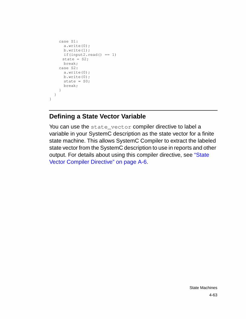
4-63
State Machines
case S1: a.write(0); b.write(1); if(input2.read() == 1)
state = S2; break; case S2: a.write(0); b.write(0); state = S0; break; } }}
Defining a State Vector Variable
You can use the state_vector compiler directive to label avariable in your SystemC description as the state vector for a finitestate machine. This allows SystemC Compiler to extract the labeledstate vector from the SystemC description to use in reports and otheroutput. For details about using this compiler directive, see “StateVector Compiler Directive” on page A-6.

4-64
Chapter 4: RTL Coding Guidelines

A-1
ACompiler Directives A
This appendix provides a list of the compiler directives you can usefor RTL synthesis with SystemC Compiler. It contains the followingsections:
• Synthesis Compiler Directives
• C/C++ Compiler Directives

A-2
Appendix A: Compiler Directives
Synthesis Compiler Directives
To specify a compiler directive (also known as a pragma) in yourSystemC code, insert a comment in which the first word issynopsys. You can use either a multiple-line comment enclosed in/* and */ characters or a single-line comment beginning with twoslash (//) characters.
Table A-1 lists the compiler directives.
Table A-1 SystemC Compiler Compiler Directives
Compiler directive Details
/* synopsys line_label string */ page A-3
/* synopsys infer_multibit signal_name_list */ page A-3
/* synopsys dont_infer_multibit signal_name_list */ page A-3
/* synopsys infer_mux signal_name_list *//* synopsys infer_mux */
page A-4
/* synopsys dont_infer_mux signal_name_list */ page A-4
/* synopsys unroll */ page A-5
/* synopsys full_case */ page A-5
/* synopsys parallel_case */ page A-6
/* synopsys state_vector string */ page A-6
/* synopsys enum */ page A-8
/*synopsys synthesis_off */ and/* synopsys synthesis_on */
page A-8
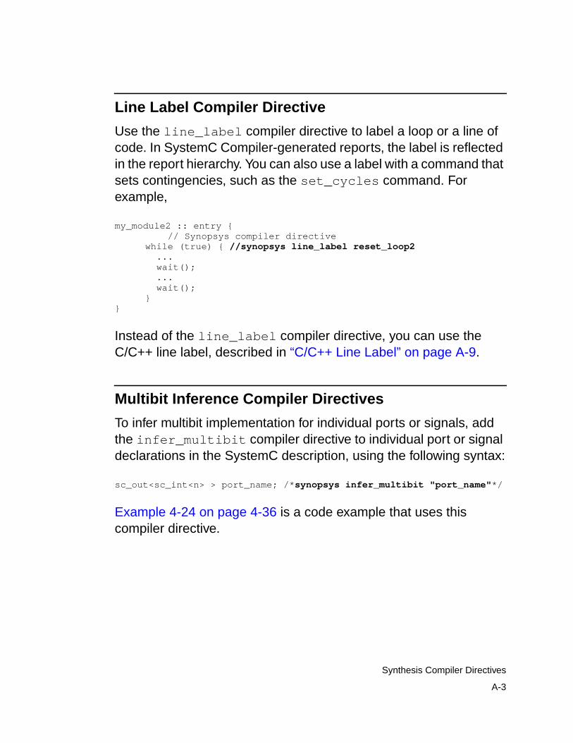
A-3
Synthesis Compiler Directives
Line Label Compiler Directive
Use the line_label compiler directive to label a loop or a line ofcode. In SystemC Compiler-generated reports, the label is reflectedin the report hierarchy. You can also use a label with a command thatsets contingencies, such as the set_cycles command. Forexample,
my_module2 :: entry { // Synopsys compiler directivewhile (true) { //synopsys line_label reset_loop2 ... wait(); ... wait();}
}
Instead of the line_label compiler directive, you can use theC/C++ line label, described in “C/C++ Line Label” on page A-9.
Multibit Inference Compiler Directives
To infer multibit implementation for individual ports or signals, addthe infer_multibit compiler directive to individual port or signaldeclarations in the SystemC description, using the following syntax:
sc_out<sc_int<n> > port_name; /*synopsys infer_multibit "port_name"*/
Example 4-24 on page 4-36 is a code example that uses thiscompiler directive.

A-4
Appendix A: Compiler Directives
To prevent multibit inference for individual ports or signals, add thedont_infer_multibit compiler directive to individual port orsignal declarations in the SystemC description, using the followingsyntax:
sc_out<sc_int<n> > port_name; /*synopsys dont_infer_multibit"port_name"*/
Example 4-25 on page 4-38 shows a code example that uses thiscompiler directive.
Multiplexer Inference Compiler Directives
To infer a multiplexer for a switch…case statement, add theinfer_mux compiler directive as the first line of code in the switchstatement, using the following syntax:
switch (var) { //synopsys infer_mux ...}
Example 4-28 on page 4-45 shows a code example that uses thiscompiler directive.
To infer a multiplexer for one or more switch…case statements withina block of code, add a line label to the block of code and use theinfer_mux compiler directive, using the following syntax:
//synopsys infer_mux "label_1"
label_1: switch (var) { ...}
Example 4-26 on page 4-40 shows a code example that uses thiscompiler directive.
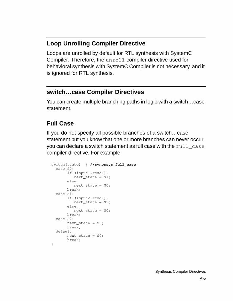
A-5
Synthesis Compiler Directives
Loop Unrolling Compiler Directive
Loops are unrolled by default for RTL synthesis with SystemCCompiler. Therefore, the unroll compiler directive used forbehavioral synthesis with SystemC Compiler is not necessary, and itis ignored for RTL synthesis.
switch…case Compiler Directives
You can create multiple branching paths in logic with a switch…casestatement.
Full Case
If you do not specify all possible branches of a switch…casestatement but you know that one or more branches can never occur,you can declare a switch statement as full case with the full_casecompiler directive. For example,
switch(state) { //synopsys full_case case S0: if (input1.read()) next_state = S1; else next_state = S0; break; case S1: if (input2.read()) next_state = S2; else next_state = S0; break; case S2: next_state = S0; break; default: next_state = S0; break; }
A-6
Appendix A: Compiler Directives
Example 4-17 on page 4-25 shows a code example that uses thiscompiler directive.
Parallel Case
SystemC Compiler automatically determines whether a switchstatement is full or parallel.
All cases of a switch statement are, by definition, mutually exclusive(parallel) in C/C++. Because of this, the parallel_case compilerdirective used by Design Compiler and other Synopsys tools isredundant. No cases overlap, by design, and a priority encoder is notnecessary, so SystemC Compiler synthesizes a multiplexer.
State Vector Compiler Directive
The state_vector directive allows you to define the state vectorof a finite state machine (and its encoding) in a SystemC description.It labels a variable in a SystemC description as the state vector for afinite state machine.
The syntax for the state_vector directive is
// synopsys state_vector vector_name
where vector_name is the variable for the state vector. Thisdeclaration allows SystemC Compiler to extract the labeled statevector from the SystemC description. Example A-1 shows one wayto use the state_vector directive.

A-7
Synthesis Compiler Directives
Note:Do not define two state_vector directives in one module.Although SystemC Compiler does not issue an error message, itrecognizes only the first state_vector directive and ignoresthe second.
Example A-1 Using the state_vector Compiler Directive#include "systemc.h"SC_MODULE( state_vector) { sc_in<sc_uint<2> > in1; sc_in_clk clock; sc_out<sc_uint<2> > out;
sc_signal<sc_uint<2> > state;//snps state_vector state sc_signal<sc_uint<2> > next_state;
void f1 (); void f2 (); void state_register ();
SC_CTOR( state_vector ) { SC_METHOD( f1); sensitive (in1); sensitive (state); SC_METHOD( f2); sensitive (state); SC_METHOD(state_register); sensitive_pos << clock; }};
void state_vector:: f1 (){ switch (state.read ().to_uint ()) { case 0: next_state = (in1.read () +1) % 4; break; case 1: next_state = (in1.read ()+2) % 4; break; case 2: next_state = (in1.read ()+4) % 4; break; case 3: next_state = (in1.read ()+8) % 4; break; }}
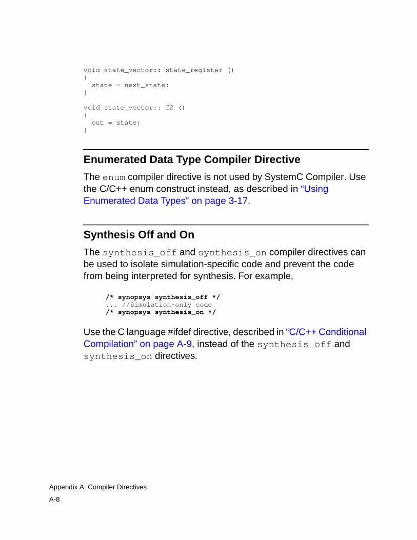
A-8
Appendix A: Compiler Directives
void state_vector:: state_register (){ state = next_state;}
void state_vector:: f2 (){ out = state;}
Enumerated Data Type Compiler Directive
The enum compiler directive is not used by SystemC Compiler. Usethe C/C++ enum construct instead, as described in “UsingEnumerated Data Types” on page 3-17.
Synthesis Off and On
The synthesis_off and synthesis_on compiler directives canbe used to isolate simulation-specific code and prevent the codefrom being interpreted for synthesis. For example,
/* synopsys synthesis_off */... //Simulation-only code/* synopsys synthesis_on */
Use the C language #ifdef directive, described in “C/C++ ConditionalCompilation” on page A-9, instead of the synthesis_off andsynthesis_on directives.
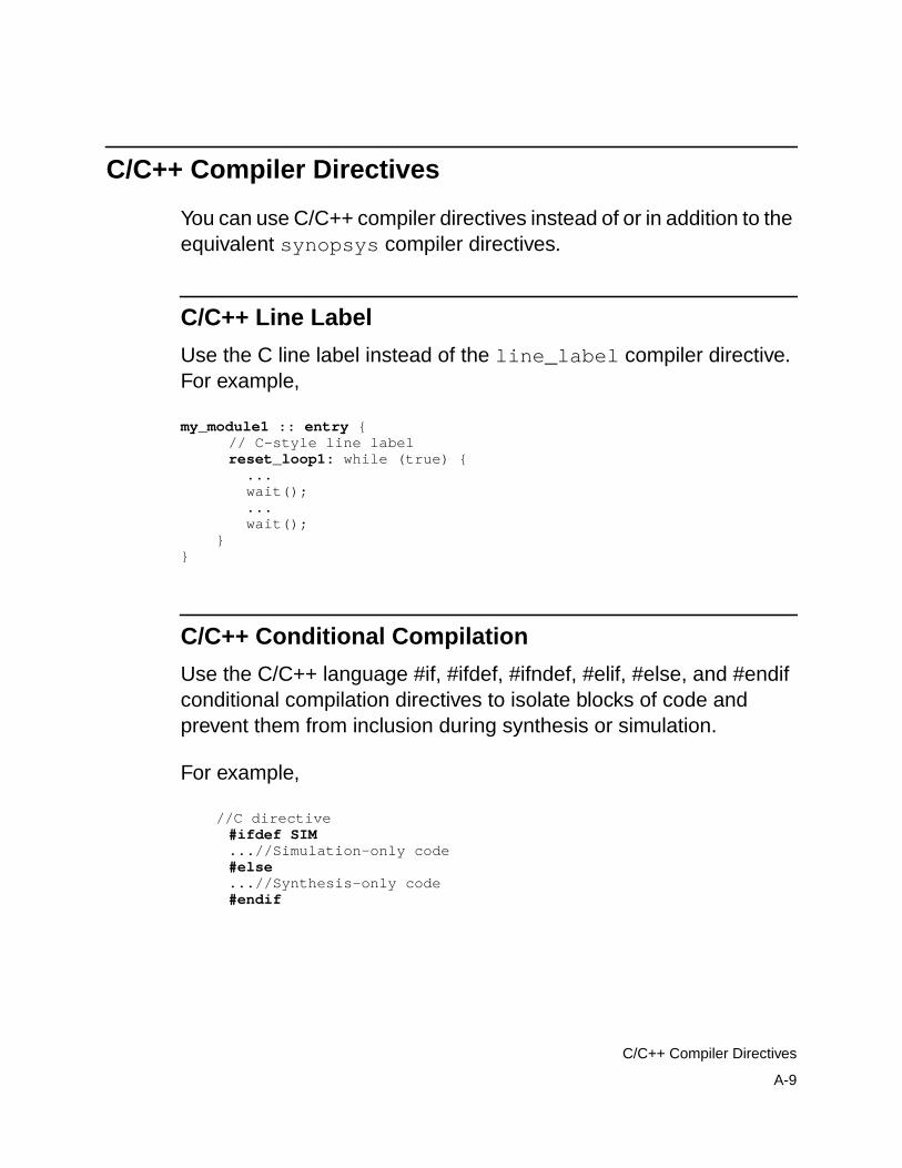
A-9
C/C++ Compiler Directives
C/C++ Compiler Directives
You can use C/C++ compiler directives instead of or in addition to theequivalent synopsys compiler directives.
C/C++ Line Label
Use the C line label instead of the line_label compiler directive.For example,
my_module1 :: entry {// C-style line labelreset_loop1: while (true) { ... wait(); ... wait();
}}
C/C++ Conditional Compilation
Use the C/C++ language #if, #ifdef, #ifndef, #elif, #else, and #endifconditional compilation directives to isolate blocks of code andprevent them from inclusion during synthesis or simulation.
For example,
//C directive#ifdef SIM...//Simulation-only code#else...//Synthesis-only code#endif

A-10
Appendix A: Compiler Directives

B-1
BExamples B
This appendix describes several examples that demonstrate thebasic concepts of RTL synthesis with SystemC Compiler. The filesfor these examples are available in the SystemC Compilerinstallation in the $SYNOPSYS/doc/syn/ccsc/ccsc_examplesdirectory.
This appendix describes the following examples:
• Count Zeros Combinational Version
• Count Zeros Sequential Version
• FIR RTL Version
• FIR RTL and Behavioral Integrated Version
• Drink Machine

B-2
Appendix B: Examples
Count Zeros Combinational Version
This circuit is a combinational specification of a design problem. Thecircuit is given an 8-bit value, and it determines
• That the value contains exactly one sequence of zeros
• That the number of zeros in the sequence (if any)
The circuit must complete this computation in a single clock cycle.The input to the circuit is an 8-bit value. The circuit produces twooutputs, the number of zeros found and an error indication.
A valid value contains only one sequence of zeros. If more than onesequence of zeros is detected, the value is invalid. A value consistingof all ones is a valid value. If a value is invalid, the count of zeros isset to zero and an error is indicated.
RTL description files are available in $SYNOPSYS/doc/syn/ccsc/ccsc_examples/count_zeros/count_zeros_comb. Table B-1provides a list of the files.
Table B-1 RTL Count Zeros Combinational Files
File name File description
readme_czero_combo.txt Description of the count zeros combination version.
count_zeros_comb.h,count_zeros_comb.cc
RTL model. The RTL description has one SC_METHODprocess and two member functions (legal and zeros).
count_zero_run_rtl.scr RTL synthesis to gates command script.
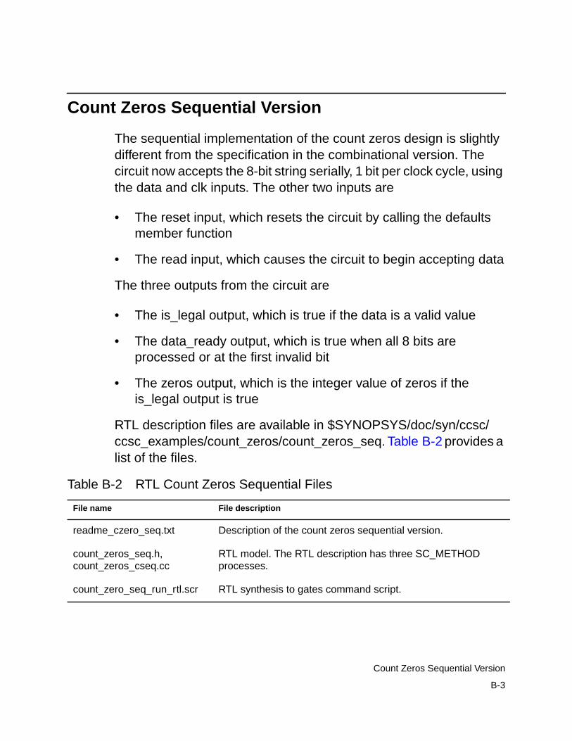
B-3
Count Zeros Sequential Version
Count Zeros Sequential Version
The sequential implementation of the count zeros design is slightlydifferent from the specification in the combinational version. Thecircuit now accepts the 8-bit string serially, 1 bit per clock cycle, usingthe data and clk inputs. The other two inputs are
• The reset input, which resets the circuit by calling the defaultsmember function
• The read input, which causes the circuit to begin accepting data
The three outputs from the circuit are
• The is_legal output, which is true if the data is a valid value
• The data_ready output, which is true when all 8 bits areprocessed or at the first invalid bit
• The zeros output, which is the integer value of zeros if theis_legal output is true
RTL description files are available in $SYNOPSYS/doc/syn/ccsc/ccsc_examples/count_zeros/count_zeros_seq. Table B-2 provides alist of the files.
Table B-2 RTL Count Zeros Sequential Files
File name File description
readme_czero_seq.txt Description of the count zeros sequential version.
count_zeros_seq.h,count_zeros_cseq.cc
RTL model. The RTL description has three SC_METHODprocesses.
count_zero_seq_run_rtl.scr RTL synthesis to gates command script.
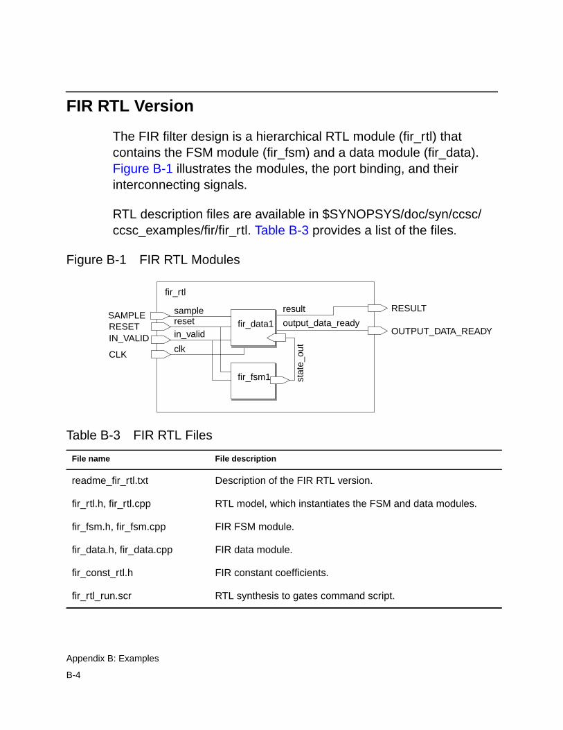
B-4
Appendix B: Examples
FIR RTL Version
The FIR filter design is a hierarchical RTL module (fir_rtl) thatcontains the FSM module (fir_fsm) and a data module (fir_data).Figure B-1 illustrates the modules, the port binding, and theirinterconnecting signals.
RTL description files are available in $SYNOPSYS/doc/syn/ccsc/ccsc_examples/fir/fir_rtl. Table B-3 provides a list of the files.
Figure B-1 FIR RTL Modules
Table B-3 FIR RTL Files
File name File description
readme_fir_rtl.txt Description of the FIR RTL version.
fir_rtl.h, fir_rtl.cpp RTL model, which instantiates the FSM and data modules.
fir_fsm.h, fir_fsm.cpp FIR FSM module.
fir_data.h, fir_data.cpp FIR data module.
fir_const_rtl.h FIR constant coefficients.
fir_rtl_run.scr RTL synthesis to gates command script.
fir_rtl
RESETIN_VALID
SAMPLE
CLK
RESULT
OUTPUT_DATA_READY
fir_fsm1 stat
e_ou
tsampleresetin_valid
clk
result
output_data_readyfir_data1

B-5
FIR RTL and Behavioral Integrated Version
FIR RTL and Behavioral Integrated Version
The FIR integrated RTL and behavioral design top-level module(all_top) contains both a behavioral module (fir_beh) and thehierarchical RTL module (fir_rtl). The inputs (sample, reset, in_valid,and clk) feed into both the RTL and behavioral modules. Figure B-2illustrates the modules and the port bindings.
RTL and behavioral integrated description files are available in$SYNOPSYS/doc/syn/ccsc/ccsc_examples/fir/fir_integrated.Table B-4 provides a list of the files.
Figure B-2 FIR RTL and Behavioral Integrated Modules
all_top
resetin_valid
sample
clk
sample_out_rtl
output_ready_rtlfir_rtl
sample_out_syn
output_ready_syn
result
RESULT
Behavioral
RTL
fir_beh

B-6
Appendix B: Examples
Table B-4 FIR RTL Files
File name File description
readme_fir_int.txt Description of the FIR RTL version.
all_top.h Instantiations of RTL and behavioral FIR modules.
fir_beh.h, fir_beh.cpp Behavioral model.
fir_rtl.h, fir_rtl.cpp RTL model, which instantiates the FSM and data modules.
fir_fsm.h, fir_fsm.cpp FIR FSM module.
fir_data.h, fir_data.cpp FIR data module.
fir_const.h FIR constant coefficients.
fir_const_rtl.h FIR constant coefficients.
all_run.scr Synthesis to gates command script.

B-7
Drink Machine
Drink Machine
The drink machine circuit is a vending machine that dispensesdrinks. It contains a state machine that counts money as input. Thedrink machine waits for a deposit of 35 cents and signals the vendingmachine to dispense a drink. If change is owed, the machine returnsit when it dispenses the drink.
RTL description files are available in $SYNOPSYS/doc/syn/ccsc/ccsc_examples/drink_machine. Table B-5 provides a list of the files.
Table B-5 RTL Drink Machine Files
File name File description
readme_drink.txt Description of the drink machine.
drink_machine.h,drink_machine.cc
RTL model. The RTL description has two SC_METHODprocesses.
drink.scr RTL synthesis to gates command script.

B-8
Appendix B: Examples
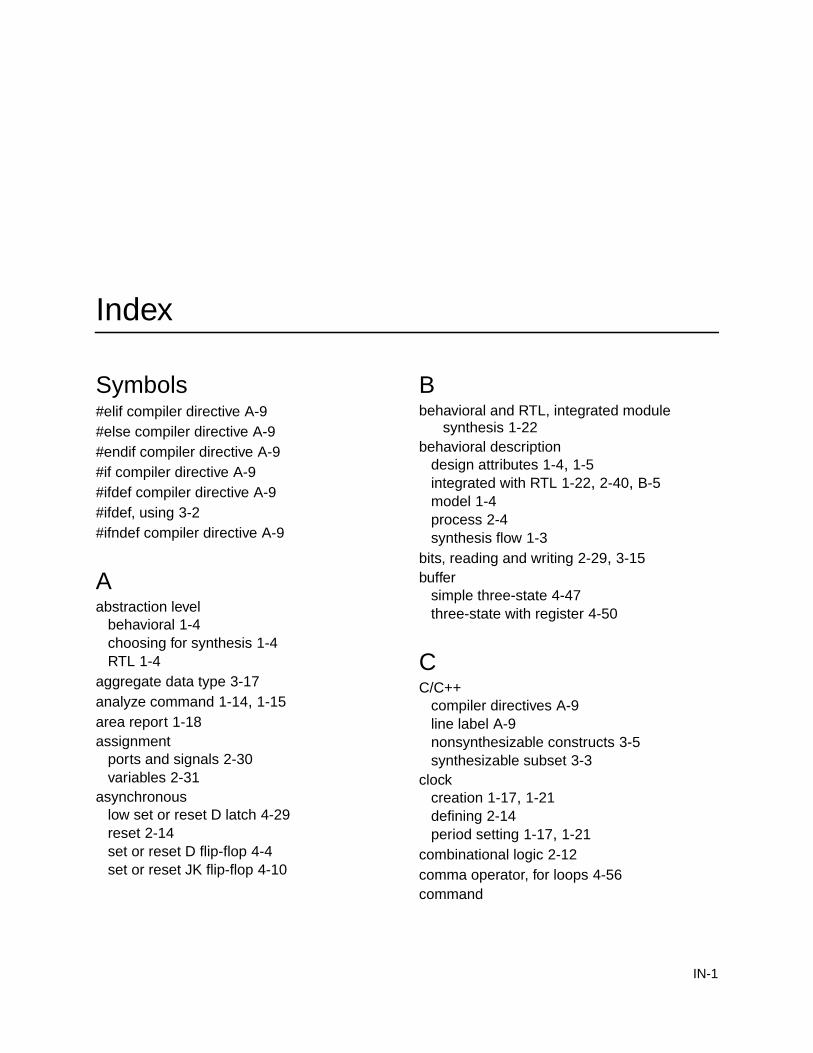
IN-1
Index
Symbols#elif compiler directive A-9#else compiler directive A-9#endif compiler directive A-9#if compiler directive A-9#ifdef compiler directive A-9#ifdef, using 3-2#ifndef compiler directive A-9
Aabstraction level
behavioral 1-4choosing for synthesis 1-4RTL 1-4
aggregate data type 3-17analyze command 1-14, 1-15area report 1-18assignment
ports and signals 2-30variables 2-31
asynchronouslow set or reset D latch 4-29reset 2-14set or reset D flip-flop 4-4set or reset JK flip-flop 4-10
Bbehavioral and RTL, integrated module
synthesis 1-22behavioral description
design attributes 1-4, 1-5integrated with RTL 1-22, 2-40, B-5model 1-4process 2-4synthesis flow 1-3
bits, reading and writing 2-29, 3-15buffer
simple three-state 4-47three-state with register 4-50
CC/C++
compiler directives A-9line label A-9nonsynthesizable constructs 3-5synthesizable subset 3-3
clockcreation 1-17, 1-21defining 2-14period setting 1-17, 1-21
combinational logic 2-12comma operator, for loops 4-56command
IN-2
entry 1-11dc_shell 1-11scripts 1-11
order 1-10command flow 1-10
hierarchical RTL module 1-19instantiated DesignWare component 1-28instantiated HDL 1-26integrated RTL and behavioral 1-22multiple RTL module 1-19single RTL module 1-9
commandsanalyze 1-14, 1-15compile 1-18
gate-level netlist 1-22compile_systemc 1-11, 1-20, 1-22
errors 1-12single or separate RTL netlist 1-15, 1-16Verilog netlist 1-14VHDL netlist 1-14
create_clock 1-17, 1-21current_design 1-20define_design_lib 1-16elaborate 1-12, 1-14, 1-15include 1-11link 1-20, 1-21read 1-23report_area 1-18report_timing 1-18write 1-13
elaborated .db 1-13gate-level netlist 1-18HDL simulation file 1-18
compile command 1-18compile_systemc command 1-11
errors 1-12hierarchial design 1-20integrated RTL and behavioral design 1-22multiple RTL modules 1-20single or separate RTL netlist 1-15, 1-16Verilog netlist 1-14
VHDL netlist 1-14compiler directives A-2
#elif, #else, #endif A-9#if, #ifdef, #ifndef A-9C/C++ A-9dont_infer_multibit 4-36full_case A-5infer_multibit 4-36, A-3infer_mux A-4line_label A-3, A-9map_to_operator 2-47parallel_case A-6preserve_function 2-43return_port_name 2-50state_vector 4-63, A-6synthesis_off A-8synthesis_on A-8unroll A-5using #ifdef 3-2using synthesis_off 3-2
compiling gate-level netlist 1-18, 1-22component
DesignWare 2-47constructor
initializing with loops 2-23module 2-16with arguments 2-18
constructsnonsynthesizable C/C++ 3-5nonsynthesizable SystemC 3-4
control logic 1-6count zeros combinational example 2-32, B-2count zeros sequential example 2-34, B-3create_clock command 1-17, 1-21creating
HDL netlist 1-13hierarchical module 2-38hierarchical RTL module B-4integrated RTL and behavioral 2-40, B-5module 2-6multiple modules 2-38

IN-3
process 2-11current_design command 1-20
DD flip-flop
simple 4-2with asynchronous set or reset 4-4with synchronous set or reset 4-7
D latchinferring 4-14with low asynchronous set or reset 4-29
datasynthesis recommendation 3-20synthesizable 3-8synthesizable C/C++ 3-3synthesizable SystemC 3-3
data memberof a module 3-18variables 2-10
data typesaggregate 3-17enumerated 3-17nonsynthesizable 3-9ports 2-8recommended for synthesis 3-10, 3-11signal 2-10synthesizable 3-9SystemC operators 3-13VHDL 3-12
databasebehavioral 1-22creating .db file 1-13hierarchical design 1-20multiple RTL module design 1-20RTL 1-22RTL and behavioral 1-23
datapath 1-6dc_shell
command entry 1-11starting 1-11
dead loop 4-56default parameter value 2-21define_design_lib command 1-16defining
control logic 1-6datapath 1-6FSM 1-6level-sensitive 2-12module 2-2, 2-6process 2-11sensitivity list 2-12
designbehavioral attributes 1-4, 1-5command order 1-10RTL attributes 1-4
design for synthesischip-level block 1-6overview 1-6pure C/C++ 1-6
design library 1-16DesignWare components 2-47DesignWare library 1-9directories
rtl_work 1-13dont_infer_multibit compiler directive 4-36drink machine B-7
Eedge-sensitive
clock 2-14inputs 2-14process 2-14sensitivity list 2-14
elaborate command 1-12, 1-14, 1-15entering commands 1-11enumerated data type 3-17examples
count zeros combinational 2-32, B-2count zeros sequential 2-34, B-3drink machine B-7

IN-4
FIR integrated RTL and behavioral 2-40, B-5FIR RTL B-4
excludingnonsynthesizable code 3-2simulation-only code 3-3
Ffiles
database .db file 1-13gate-level netlist 1-9RTL HDL 1-9separate RTL netlist 1-15single RTL netlist 1-15
FIR integrated RTL and behavioral example2-40, B-5
FIR RTL example B-4flip-flop
inference 4-2inferring D with asynchronous set or reset
4-4inferring D with synchronous set or reset 4-7inferring JK 4-9inferring JK with asynchronous set or reset
4-10inferring JK with synchronous set or reset 4-9simple D 4-2
for loopcomma operator 4-56
FSMdefinition 1-6description 4-57
full_case compiler directive A-5functions
member 2-15preserving 2-43
Ggate-level
writing netlist 1-18, 1-22writing simulation file 1-18
HHDL
creating netlist 1-13RTL file 1-9
hdlin_enable_presto variable 1-14, 1-15hdlin_infer_multibit variable 4-36hdlin_unsigned_integers variable 1-14, 1-15header file
module 2-6hierarchical design 1-20
command flow 1-19hierarchical module
creating 2-38RTL B-4
Iimplementation, module 2-16include command 1-11incomplete sensitivity list 2-13infer_multibit compiler directive 4-36, A-3infer_mux compiler directive A-4inference
flip-flop 4-2latch 4-14multibit 4-35multiplexer 4-39register 4-2three-state 4-47
inferringD latch 4-14JK flip-flop 4-9
inout port 2-7input port 2-7inputs
edge-sensitive 2-14level-sensitive 2-12
inputs to SystemC Compiler 1-7instantiated DesignWare component
command flow 1-28

IN-5
instantiated HDLcommand flow 1-26
integrated RTL and behavioral 1-22command flow 1-22creating 2-40, B-5synthesis 1-22
JJK flip-flop
inferring 4-9with asynchronous set or reset 4-10with synchronous set or reset 4-9
Llabel
C/C++ line label A-9line_label compiler directive A-3
latchavoiding 4-14D with low asynchronous set or reset 4-29inference 4-14SR 4-15
level-sensitive 2-12inputs 2-12sensitivity list 2-12
librarydesign 1-16DesignWare 1-9synthetic 1-7, 1-8, 1-9technology 1-7, 1-8work 1-16
limitationsmultiplexer inference 4-46register inference 4-32sensitivity lists 2-15three-state inference 4-53
line_label compiler directive A-3, A-9link command 1-20, 1-21logic
combinational 2-12sequential 2-14
loops 4-53dead 4-56unrolled 4-55unrolling A-5
Mmacros
SC_CTHREAD 2-5SC_CTOR 2-16SC_HAS_PROCESS 2-18SC_METHOD 2-5SC_THREAD 2-4
map_to_operator compiler directive 2-47member functions 2-15module
constructor 2-16constructor arguments 2-18contents 2-2creating 2-6creating multiple 2-38data members 3-18defining 2-2defining parameters 2-18header file 2-6implementation 2-16instantiating with a loop 2-25parameter passing 1-23ports 2-7SC_HAS_PROCESS 2-18SC_MODULE 2-7signal communication 2-8syntax 2-6
multibit inference 4-35multiple modules
creating 2-38RTL 1-20
multiplexer inference 4-39limitations 4-46

IN-6
Nnetlist
gate_level 1-9single or separate RTL file 1-15
nonsynthesizable code, excluding 3-2nonsynthesizable data types 3-9
Ooperators
SystemC data type 3-13output port 2-7outputs from SystemC Compiler 1-7
Pparallel_case compiler directive A-6parameter
default value 2-21defining 2-18passing values 2-20passing values from command line 1-23
period, clock 1-17, 1-21port type
sc_in 2-7sc_inout 2-7sc_out 2-7
ports 2-7assignment 2-30data types 2-8read 2-28read and write 2-28read bits 2-29, 3-15sc_in 2-28sc_inout 2-28sc_out 2-28syntax 2-8
pragmaSee compiler directives
preserve_functioncompiler directive 2-43
processbehavioral 2-4creating in a module 2-11edge-sensitive 2-14execution 2-3level-sensitive 2-12read and write 2-4registering 2-3RTL 2-4SC_CTHREAD 2-4, 2-5SC_METHOD 2-4, 2-5SC_THREAD 2-4sensitivity list 2-4, 2-12trigger 2-4types 2-4
Rread
from ports 2-4port 2-28port bits 2-29, 3-15ports 2-28signal bits 2-29, 3-15signals 2-28
read command 1-23register
inference 4-2inference limitations 4-32
registering a process 2-3report_area command 1-18report_timing command 1-18reports
area 1-18timing 1-18
reset, asynchronous 2-14return_port_name compiler directive 2-50rolled and unrolled loops A-5RTL
design attributes 1-4design description 1-8
IN-7
hierarchical module 1-19, B-4instantiated DesignWare component 1-28instantiated HDL 1-26integrated module 1-22integrated with behavioral 1-22model 1-4process 2-4synthesis command flow 1-9synthesis commands for integrated modules
1-22synthesis commands for multiple modules
1-19synthesis flow 1-3
RTL and behavioralintegrated module synthesis 1-22
RTL integrated with behavioral 2-40, B-5rtl_work directory 1-13
Ssaving, database .db file 1-13SC_CTHREAD
macro 2-5process 2-4, 2-5
SC_CTORmacro 2-16
SC_HAS_PROCESSmacro 2-18
sc_in port 2-28sc_in port type 2-7sc_inout port 2-28sc_inout port type 2-7SC_METHOD
macro 2-5process 2-4, 2-5
SC_MODULEmodule 2-7syntax 2-7
sc_out port 2-28sc_out port type 2-7SC_THREAD
macro 2-4process 2-4
sensitive() 2-12sensitive_neg() 2-12sensitive_pos() 2-12sensitivity list 2-12
defining 2-12edge-sensitive 2-14incomplete 2-13level-sensitive 2-12limitations 2-15
sequential logic 2-14signal 2-8
assignment 2-30communication between processes 2-4data types 2-10read 2-28read and write 2-4read bits 2-29, 3-15syntax 2-9
simulation, gate-level HDL file 1-18simulation-only code, excluding 3-3source code, RTL 1-8SR latch 4-15start dc_shell 1-11state machine description 4-57state_vector compiler directive 4-63, A-6struct 3-17subset, synthesizable 3-2synchronous
set or reset D flip-flop 4-7set or reset JK flip-flop 4-9
synopsys compiler directive A-2syntax
module 2-6, 2-7port 2-8signal 2-9
synthesischoosing abstraction level 1-4creating .db file 1-13
IN-8
creating .db for behavioral module 1-22creating .db for hierarchical design 1-20creating .db for integrated RTL and
behavioral module 1-23creating .db for multiple RTL modules 1-20creating .db for RTL module 1-22creating HDL netlist 1-13data 3-8data recommendation 3-20data types 3-9defining control logic 1-6defining datapath 1-6defining FSM 1-6excluding nonsynthesizable subset 3-2modifying functional model 1-6recommended data types 3-10, 3-11subset 3-5synthesizable subset 3-2
synthesis flow 1-3commands 1-9commands for integrated modules 1-22commands for multiple modules 1-19
synthesis_off compiler directive A-8synthesis_off, using 3-2synthesis_on compiler directive A-8synthetic library 1-7, 1-8
location 1-9synthetic_library variable 1-8SystemC
data type operators 3-13nonsynthesizable constructs 3-4RTL description 1-8synthesizable subset 3-3
Ttarget_library variable 1-8technology library 1-7, 1-8
location 1-8
three-stateinference 4-47inference limitations 4-53simple buffer 4-47with register 4-50
timing report 1-18triggering a process 2-4typedef 3-17
Uunroll compiler directive A-5unrolled loops 4-55using scripts 1-11
Vvariables
assignment 2-31data members 2-10hdlin_enable_presto 1-14, 1-15hdlin_infer_multibit 4-36hdlin_unsigned_integers 1-14, 1-15read and write 2-4synthetic_library 1-8target_library 1-8
VHDL data type conversion 3-12
Wwork library 1-16write
elaborated .db 1-13gate-level netlist 1-18, 1-22gate-level netlist for synthesis 1-18HDL simulation file 1-18port 2-28to ports 2-4