coccooco 2222 based refrigeration systems · advansor offers refrigeration systems (compressor...
TRANSCRIPT

COCOCOCO based refrigeration systems based refrigeration systems based refrigeration systems based refrigeration systems COCOCOCO2222 based refrigeration systems based refrigeration systems based refrigeration systems based refrigeration systems for heating and coolingfor heating and coolingfor heating and coolingfor heating and cooling
ÅrhusÅrhusÅrhusÅrhus14. maj 200914. maj 200914. maj 200914. maj 2009
Kim G. ChristensenKim G. ChristensenKim G. ChristensenKim G. Christensen

About ADVANSOR www.advansor.dk� ADVANSOR is specialized in CO2-technologies within the fields of
refrigeration and heat pumps
� ADVANSOR has 8 employees and a turnover of 3 mill. euro
� ADVANSOR develops, manufacturers and sell projects within� Combined Heating and PowerCombined Heating and PowerCombined Heating and PowerCombined Heating and Power� Process industryProcess industryProcess industryProcess industry� Food industryFood industryFood industryFood industry� SupermarketsSupermarketsSupermarketsSupermarkets
� Our products are:� Heat pumps Heat pumps Heat pumps Heat pumps 20202020----1000 kW1000 kW1000 kW1000 kW� Chillers / ACChillers / ACChillers / ACChillers / AC----systemssystemssystemssystems 80808080----400 kW400 kW400 kW400 kW� Supermarket refrigerationSupermarket refrigerationSupermarket refrigerationSupermarket refrigeration 6/15 6/15 6/15 6/15 –––– 50/250 kW50/250 kW50/250 kW50/250 kW� Light commercialLight commercialLight commercialLight commercial 100100100100----1000 kW1000 kW1000 kW1000 kW� Costumer specified productsCostumer specified productsCostumer specified productsCostumer specified products Engineering, design, production of series of 5Engineering, design, production of series of 5Engineering, design, production of series of 5Engineering, design, production of series of 5----10 units 10 units 10 units 10 units
� We work closely together with partners and suppliers and have cooperation with Danish associations, private research institutes and universities, EPA and the Ministry of Transport and Energy as well as the Danish Industry

Markedsmæssige træk for CO2-køleanlæg
� HFC - lovgivning: Max 10 kg HFC pr kreds – i praksis begrænsning på 30-60 kW for luftkølede aggregater
� Andre naturlige kølemidler� giftige eller brændbaregiftige eller brændbaregiftige eller brændbaregiftige eller brændbare� tørkøleropstillinger med forhøjet energiforbrugtørkøleropstillinger med forhøjet energiforbrugtørkøleropstillinger med forhøjet energiforbrugtørkøleropstillinger med forhøjet energiforbrug
� CO2 påtænkt at lukke hullet optil større kaskadeanlæg � området mellem 30området mellem 30området mellem 30området mellem 30----400 kW400 kW400 kW400 kW
CO2-konkurrenter (transkritisk)
� Knudsen/ PVN (Danmark)
� Green and Cool (Sverige)
� Linde/ Carrier (Tyskland)
� Fischer (Tyskland)
� Dresdner Kühlanlagenbau (Tyskland)
� Costan (Italien)
� Enex (Italien)
� Blue Wave (Italien)� området mellem 30området mellem 30området mellem 30området mellem 30----400 kW400 kW400 kW400 kW
� Blue Wave (Italien)
Primære markeder
� Supermarkeds køl (Nordeuropa)
� Industriel køl/ frys (dx)
� Varmepumper (høje temperaturer)
� comBINE anvendelser
� Aircondition (chillere og dx)

ADVANSOR’s products
compHEAT: CHP – combined heat and powerAdvansor develops heat pump solutions dedicated to power
plants operated by either gas motor or gas turbines.
The heat pump produces hot water up to 90°C which enables
direct pipe connection to the external pipe work with no
interference with the motor and piping.
compBINE: Combined heating and coolingCombined heating and cooling - produce hot water up to 100°C
and get ice water for free or counter wise. Advansor’s product
line is highly suitable in connection with pasteurisation, CIP
systems and other application in food industry where coinciding
demands for heating and cooling exist. Combined heating and
cooling saves both capital investment and energy cost.cooling saves both capital investment and energy cost.
compFORT: Chiller applications and AC systemsAdvansor offers highly compact air cooled chillers and AC
systemsin the range from 100 to 400 kW. With natural
refrigerant, no toxic risk and no flammability this is a safe and
economical feasible choice.
compSUPER: Refrigeration applicationsAdvansor offers refrigeration systems (compressor rack’s) for
supermarkets and other commercial/ industrial applications.
The units work with as the only refrigerant. Main focus are
placed on reliability, ease of service and low energy
consumption.


Characteristics of CO2
Benefits:
� Environmentally friendly refrigerant (ODP = 0, GWP = 1)
� Smaller pipe dimensions
� Better efficiency of compressors
� Better heat transfer
Safety issues:
� Group L1 – no flammability and no toxicity
� No restriction regarding installation and use – easy to install
CO2
� No restriction regarding installation and use – easy to install
� Temperature/ pressure: -55 -> +31°C (5.5 -> 73 bar)
� Heavier than air
Challenges :
� High pressures (120 bar)
� Standstill pressure
� Use of safety valves
� Separation of oil and liquid from CO2 gas
� Energy efficiency / price

Transcritical versus subcritical operation
60
70
80
90
100
110
120
130
140
T [
°C]
0,0
017
0,0
1
0,0
19
0,0
34
CarbonDioxideOverhedet gas
Transkritisk:Ingen faseskifte ved varmeafgivelseIngen faseskifte ved varmeafgivelseIngen faseskifte ved varmeafgivelseIngen faseskifte ved varmeafgivelse[T, p] er indbyrdes uafhængige[T, p] er indbyrdes uafhængige[T, p] er indbyrdes uafhængige[T, p] er indbyrdes uafhængigeTryk for optimal COPTryk for optimal COPTryk for optimal COPTryk for optimal COPGod afkøling vigtig for optimal COPGod afkøling vigtig for optimal COPGod afkøling vigtig for optimal COPGod afkøling vigtig for optimal COPpinch point skal undgås i vekslerenpinch point skal undgås i vekslerenpinch point skal undgås i vekslerenpinch point skal undgås i vekslerenSubkritisk: ”business as usual”
FordeleFordeleFordeleFordelesmå dimensioner
materiale valg
Transition:
-1,60 -1,40 -1,20 -1,00 -0,80-10
0
10
20
30
40
50
60
s [kJ/kg-K]
T [
°C]
60 bar
35 bar
18,7 bar
70 bar
0,2 0,4 0,6 0,8
Superkritisk fluid
Transition:Anlægget kører i de 2 driftsformerAnlægget kører i de 2 driftsformerAnlægget kører i de 2 driftsformerAnlægget kører i de 2 driftsformer
styring
anlæggets udformning

Fundamental concerns
� High pressure components – stand-still pressure� Leak tight system� Oil management� Noise and vibration� Water in the system
� System design and choice of components� Availability of components� Reliability of components� Reliability of components� All systems/ components tested before going into the market
… heavy tests for 1 year
� Controllers (Danfoss, industrial PLC – Simens/ Beckhoff)
� Energy consumption� PED and approval by Notified Body� Education of installers and technicians� Prices that can bring the technology to the market

Fundamental design and considerations � High pressure side/ low pressure side – 120 and 40/25 bar
� Standstill pressure for receiver Standstill pressure for receiver Standstill pressure for receiver Standstill pressure for receiver –––– 90 bar (refrigerant stays on the system)90 bar (refrigerant stays on the system)90 bar (refrigerant stays on the system)90 bar (refrigerant stays on the system)� Tightness = hermetic solutions
� Welded carbon steel, semihermetic compressorsWelded carbon steel, semihermetic compressorsWelded carbon steel, semihermetic compressorsWelded carbon steel, semihermetic compressors� Conical treads, metal seal, no elastomersConical treads, metal seal, no elastomersConical treads, metal seal, no elastomersConical treads, metal seal, no elastomers
� Advanced oil management � Oil coolingOil coolingOil coolingOil cooling� Oil separator with filter (99.98 % oil separation), Oil level controlOil separator with filter (99.98 % oil separation), Oil level controlOil separator with filter (99.98 % oil separation), Oil level controlOil separator with filter (99.98 % oil separation), Oil level control
� Noise and vibrations� Flexible hoses, vibrations shoes, supports of pipingFlexible hoses, vibrations shoes, supports of pipingFlexible hoses, vibrations shoes, supports of pipingFlexible hoses, vibrations shoes, supports of piping� Low velocities and no sharp edges and continuous optimizationLow velocities and no sharp edges and continuous optimizationLow velocities and no sharp edges and continuous optimizationLow velocities and no sharp edges and continuous optimization� Low velocities and no sharp edges and continuous optimizationLow velocities and no sharp edges and continuous optimizationLow velocities and no sharp edges and continuous optimizationLow velocities and no sharp edges and continuous optimization
� System design for high reliability� Integrated oil cooling, liquid separator and suction gas heat exchangerIntegrated oil cooling, liquid separator and suction gas heat exchangerIntegrated oil cooling, liquid separator and suction gas heat exchangerIntegrated oil cooling, liquid separator and suction gas heat exchanger� Suction gas filters, filter driers to remove water from the systemSuction gas filters, filter driers to remove water from the systemSuction gas filters, filter driers to remove water from the systemSuction gas filters, filter driers to remove water from the system
� System design (for low energy consumption)� Optimized compressor design and oOptimized compressor design and oOptimized compressor design and oOptimized compressor design and optimized gasptimized gasptimized gasptimized gas----cooler designcooler designcooler designcooler design� Adiabatic humidification of the gasAdiabatic humidification of the gasAdiabatic humidification of the gasAdiabatic humidification of the gas----cooler, heat recovery is integrated on requestcooler, heat recovery is integrated on requestcooler, heat recovery is integrated on requestcooler, heat recovery is integrated on request
� Safety issues - The system is CE-marked from the manufacturer� All design specifications are satisfied All design specifications are satisfied All design specifications are satisfied All design specifications are satisfied
Mechanical: MD(98/37/EC) / PED(97/23/EC) / EN378 / EN13480 / EN13445Mechanical: MD(98/37/EC) / PED(97/23/EC) / EN378 / EN13480 / EN13445Mechanical: MD(98/37/EC) / PED(97/23/EC) / EN378 / EN13480 / EN13445Mechanical: MD(98/37/EC) / PED(97/23/EC) / EN378 / EN13480 / EN13445Electrical: LVD(06/95/EC) / EMC(89/336/EC) / EN60204Electrical: LVD(06/95/EC) / EMC(89/336/EC) / EN60204Electrical: LVD(06/95/EC) / EMC(89/336/EC) / EN60204Electrical: LVD(06/95/EC) / EMC(89/336/EC) / EN60204----1111
� Pressostats and safety valvesPressostats and safety valvesPressostats and safety valvesPressostats and safety valves


Systems for supermarkets – trends of development

Design of systems
� Calculation of the cycle
� Calculation of pressure drop
� Design of piping
� Compressor calculation
� Design of condenser
ηis,HT = 0,6614 [-]
ηis,LT = 0,5 [-]
λHT = 0,7459 [-]
λLT = 0,8 [-]
Pm = 35 [Bar]
te,HT = -10 [°C]
te,LT = -35 [°C]
tgk,ud = 32 [°C]
VHT = 35,37 [m3/h]
VLT = 9,379 [m3/h]
Pgk,ud = 90 [Bar]
compSUPER
WHT = 41,07 [kW]
WLT = 3,601 [kW]
Other
Other
Low temp.Medium temp.
Evap. temp.
Super heat
Epsilon ihx
Capacity
te,HT = -10 [°C] te,LT = -35 [°C]
toh,HT = 10 [K] toh,LT = 10 [K]
QHT = 60 [kW] QLT = 15 [kW]
εHT = 0,01 [-] εLT = 0,1 [-]
Advansor A/S, 04-02-2008
QHT,komp = 78,6
2xTCS373=2x12,6=25,2 m3/h
SCC250=3,86
Qc = 119,7
SCC300=5,3
SCC380=8,47
U = 400 [V] I = 70,86 [A]
Wtotal = 44,68
COPtotal = 1,68 [-]
SCC180=2,89
SCC350=6,75
SCC250+350=10,6m3
IHT = 65,15
ILT = 5,711
t2 = 117,7 [°C]
t2 = 117,7 [°C]
TCS362/4 + TCS362 = 16,1 m3/h
t1 = 0,5052 [°C]
dTunuse = 0
Qohf = 0,01225 [kW]
Quk = 0 [kW]
T16,2 = 50
Tgk,ud2 = 32
t16 = 50,19 [°C]
t15 = -24,97 [°C]
Optimal COP
Fixed pressure
� Design of condenser
� Design of valves (ICMT/ ETS)
� Receiver size
� Oil management
� PI + BOM
� SolidWorks for the construction


Installation og operation
� Turn-key project from Advansor� Compressor rackCompressor rackCompressor rackCompressor rack� CondenserCondenserCondenserCondenser� Evaporators, valves and controllersEvaporators, valves and controllersEvaporators, valves and controllersEvaporators, valves and controllers
� Installation� Connection of pipes for condenser (steel)Connection of pipes for condenser (steel)Connection of pipes for condenser (steel)Connection of pipes for condenser (steel)� Connection of evaporators (cupper pipes)Connection of evaporators (cupper pipes)Connection of evaporators (cupper pipes)Connection of evaporators (cupper pipes)� Connection of evaporators (cupper pipes)Connection of evaporators (cupper pipes)Connection of evaporators (cupper pipes)Connection of evaporators (cupper pipes)� Programming of controllers and electrical wiringProgramming of controllers and electrical wiringProgramming of controllers and electrical wiringProgramming of controllers and electrical wiring
� Start-up� Leak test, pressure test and evacuationLeak test, pressure test and evacuationLeak test, pressure test and evacuationLeak test, pressure test and evacuation� Installation of filters and driers + filling of oilInstallation of filters and driers + filling of oilInstallation of filters and driers + filling of oilInstallation of filters and driers + filling of oil� Filling of CO2 gas and filling of CO2 liquidFilling of CO2 gas and filling of CO2 liquidFilling of CO2 gas and filling of CO2 liquidFilling of CO2 gas and filling of CO2 liquid� StartStartStartStart----up of MT and LTup of MT and LTup of MT and LTup of MT and LT

Service and maintanance
� User manual
� Service description� OilOilOilOil� Filers and driersFilers and driersFilers and driersFilers and driers� CO2 level and oil levelCO2 level and oil levelCO2 level and oil levelCO2 level and oil level� Service of semi hermetic compressorsService of semi hermetic compressorsService of semi hermetic compressorsService of semi hermetic compressors� Service of heat exchangersService of heat exchangersService of heat exchangersService of heat exchangers� Service of heat exchangersService of heat exchangersService of heat exchangersService of heat exchangers
� General procedure� PumpPumpPumpPump----down to receiverdown to receiverdown to receiverdown to receiver� Relief of gasRelief of gasRelief of gasRelief of gas� Fulfillment of maintenanceFulfillment of maintenanceFulfillment of maintenanceFulfillment of maintenance� Evacuation, pressurization with CO2 and restartEvacuation, pressurization with CO2 and restartEvacuation, pressurization with CO2 and restartEvacuation, pressurization with CO2 and restart


Energy consumption for simple single stage
By Transkritisk
[MWh]
Subkritisk [MWh] Besparelse,
transkritisk [%]
Stockholm 64,1 68,0 6
København 65,5 69,1 5
Amsterdam 70,6 72,0 2
Berlin 72,9 72,9 0
Paris 76,6 74,5 -3Paris 76,6 74,5 -3
Lyon 80,8 77,0 -5
Madrid 89,1 82,2 -8
Marseille 91,9 83,1 -11
Barcelona 93,1 83,1 -12
Rom 95,0 85,0 -12
Reference: DTU, Technical University of Denmark (IPU)

Energy consumption (booster vs. cascade) (-20%)


compSUPER S 2x2 (20x10 kW) - FAKTA
4
5
6
7
8
9
10
11
Jan Feb Mar Apr Maj Juni Juli Aug Sept Okt Nov Dec
En
erg
ifo
rbru
g [
kW
h/
h]
Max CO2 - trans
Mid CO2 - trans
Min CO2 - trans
Max CO2 - kaskade
Mid CO2 - kaskade
Min CO2 - kaskade
Max R134a
Mid R134a
Min R134a

compSUPER S 2x2B
Kapacitet: 20-40 kW (frekvensomformer)
Anlægget: LxHxW = 1600x2100x780 mm
Vægt: 1000 kg

compSUPER S 2x2B til Gate Gourmet -inddækket

compSUPER XL 4x3 (70x25 kW)
Indendørsopstilling:
Anlægget: LxHxW = 3350x1895x780 mm
Rammer kan adskilles:
Køl: LxHxW = 2450x1895x780 mm
Frost: LxHxW = 2450x1895x780 mm
Receiver: LxHxW = 900x1895x780 mm
Vægt: 1650 kg

compSUPER XL 4x3B - SuperBrugsen
Benefits from compSUPER XL
� Reliability� Optimized oil management systemOptimized oil management systemOptimized oil management systemOptimized oil management system� Protection against excessive pressureProtection against excessive pressureProtection against excessive pressureProtection against excessive pressure� Pressure management during electrical Pressure management during electrical Pressure management during electrical Pressure management during electrical
cutcutcutcut----outoutoutout� Documented componentsDocumented componentsDocumented componentsDocumented components
� Energy consumption� Software tools of optimizationSoftware tools of optimizationSoftware tools of optimizationSoftware tools of optimization� Software tools of optimizationSoftware tools of optimizationSoftware tools of optimizationSoftware tools of optimization� Optimized controlsOptimized controlsOptimized controlsOptimized controls� Selection of componentsSelection of componentsSelection of componentsSelection of components� Documented lowest energy Documented lowest energy Documented lowest energy Documented lowest energy
consumptionconsumptionconsumptionconsumption� Optimized layout
� 3D design of all racks3D design of all racks3D design of all racks3D design of all racks� Optimized for lo production cost and Optimized for lo production cost and Optimized for lo production cost and Optimized for lo production cost and
low service costlow service costlow service costlow service cost

compSUPER XL 4x3B
� LT capacity:
� 45 kW at 45 kW at 45 kW at 45 kW at ----30303030°°°°CCCC� 3 x Bitzer HC compressors3 x Bitzer HC compressors3 x Bitzer HC compressors3 x Bitzer HC compressors
� MT capacity:� 80 kW at 80 kW at 80 kW at 80 kW at ----10101010°°°°CCCC� 4 x Bitzer TC compressors4 x Bitzer TC compressors4 x Bitzer TC compressors4 x Bitzer TC compressors
� MP-Receiver: 130 liter, featuring� system pump down system pump down system pump down system pump down � 90 bar design pressure90 bar design pressure90 bar design pressure90 bar design pressure
� Design pressures:� Design pressures:� 25/40/120 bar25/40/120 bar25/40/120 bar25/40/120 bar
� Individual compressor� Oil management systemOil management systemOil management systemOil management system� saftety pressure switchsaftety pressure switchsaftety pressure switchsaftety pressure switch
� Air cooled gas cooler� 35 dBa 10 m35 dBa 10 m35 dBa 10 m35 dBa 10 m� Optimised high pressure and sub Optimised high pressure and sub Optimised high pressure and sub Optimised high pressure and sub
cooling controlcooling controlcooling controlcooling control

compSUPER S 1x0/ 2x0Small medium temperature applications
T_e = -15->+10°°°°C
Capacities: 10-80 kW
Kapacitet: 40 kW (frekvensomformer)
Anlægget: LxHxW = 1200x1500x780 mm
Vægt: 300 kg
Kapacitet: 80 kW (frekvensomformer)
Anlægget: LxHxW = 2000x1500x780 mm
Vægt: 450 kg


Partial heat recovery from CO2 – refrigeration systems
40
60
80
100
120
Try
kg
as [
C]
15%
20%
25%
30%
35%
40%
45%
An
del
af
Q_c d
er
gen
vin
des
Trykgastemperatur
Andel VGV af Q_c
0
20
40
COP_NH3 COP_propan COP_CO2
Try
kg
as [
C]
0%
5%
10%
15%
An
del
af
Q_c d
er
gen
vin
des
T_e = -10C
eta_is = 0,65
T_c = 20C
T_VGV = 22C

Partiel varmegenvinding - systemudformning
+25C+50C
Heat recovery
unitAir cooled condenser
High pressure valve
Valve for gas-by-pass
Min. temp. = 25°CValve closes at 25°C
Control valve and
pump on water side
T2
P2
Fans
F1
T3
T1
30
40
50
60
70
80
Tem
pera
ture
- w
ate
r, a
ir,
refr
igera
nt
[°C
]
tvand[i]
Heat recovery unit
mdot;ref=0,3 [kg/s]
Pgk=65 [bar]
mdot;luft=6 [kg/s]
mdot;vand=0,3 [kg/s] tgk;ind=90 [°C]
tluft;ind=14 [°C]
tluft;ud=22 [°C]
tvand;ind=25 [°C]
tvand;ud=50 [°C]
tref;intermidiate=29,57 [ ]
Intermidiate pressure receiver
246810121416182022242628303234363840424446485052545658606264666870727476788082848688909294969810010
20
Enthaly steps [0=ref entrance/ 100 ref exit]
Tem
pera
ture
- w
ate
r, a
ir,
refr
igera
nt
[°C
]
50%50%
Aircooled condenser
Qluft=48,5 [kW] Qvand=31,5 [kW]
AVGV=12,99 [m 2̂]
UAVGV=2,598 [kW * m 2̂]
� Høj effektivitet under VGV� Kold udeluft udnyttes i kondensator til underkølingKold udeluft udnyttes i kondensator til underkølingKold udeluft udnyttes i kondensator til underkølingKold udeluft udnyttes i kondensator til underkøling
� Styring/ design væsentlig for at undgå kondensering, kogning,
� Design væsentlig for at undgå pinch problemer

Køleanlæg med fuld varmegenvinding: Transkritisk varmepumpedrift
50
60
70
80
90
Tem
pera
ture
- w
ate
r, a
ir, re
frig
era
nt [°
C]
tvand[i]
mdot;ref=0,5 [kg/s]Pgk=75 [bar]
mdot;luf t=2,6 [kg/s]
mdot;vand=0,55 [kg/s]tgk;ind=110 [°C]
tluf t;ind=10 [°C]tluf t;ud=15 [°C]
tvand;ind=10 [°C]tvand;ud=60 [°C]
tref ;intermidiate=29,57 [ ]tvgv;ud=32,15 [ ]
24681012141618202224262830323436384042444648505254565860626466687072747678808284868890929496981000
10
20
30
40
Enthaly steps [0=ref entrance/ 100 ref exit]
Tem
pera
ture
- w
ate
r, a
ir, re
frig
era
nt [°
C]
Heat recovery unitAircooled condenser
Qluf t=14,3 [kW]Qvand=115,5 [kW]
mdot;luf t=2,6 [kg/s]
AVGV=16,68 [m 2̂]UAVGV=10,01 [kW * m 2̂]

Driftskonditioner med partiel/fuld varmegenvinding (VGV) – eksempel 100 kW køl
� Køleanlæg� Min. kondenseringstrykstyringMin. kondenseringstrykstyringMin. kondenseringstrykstyringMin. kondenseringstrykstyring� COP 5,9 ved Pc= 52 bar, UK3COP 5,9 ved Pc= 52 bar, UK3COP 5,9 ved Pc= 52 bar, UK3COP 5,9 ved Pc= 52 bar, UK3� 30 kW VGV kapacitet30 kW VGV kapacitet30 kW VGV kapacitet30 kW VGV kapacitet� Effektoptag 20,3 kWEffektoptag 20,3 kWEffektoptag 20,3 kWEffektoptag 20,3 kW
� VGV mode60
70
80
90
100
110
120
130
T [°
C]
0,0
017
0,0
1
0,0
19
0,0
34
0,0
63
m3/
kg
� VGV mode� COP 3,8 COP 3,8 COP 3,8 COP 3,8 � 80 bar/1580 bar/1580 bar/1580 bar/15ooooC ud af gaskølerC ud af gaskølerC ud af gaskølerC ud af gaskøler� 128 kW VGV 20C ud128 kW VGV 20C ud128 kW VGV 20C ud128 kW VGV 20C ud� Effektoptag 35 kWEffektoptag 35 kWEffektoptag 35 kWEffektoptag 35 kW
� Ekstra el-effekt: � 15 kW til ca 100 kW varme15 kW til ca 100 kW varme15 kW til ca 100 kW varme15 kW til ca 100 kW varme� ”6,7 effektfaktor til VGV””6,7 effektfaktor til VGV””6,7 effektfaktor til VGV””6,7 effektfaktor til VGV” -1,8 -1,6 -1,4 -1,2 -1 -0,8 -0,6
-20
-10
0
10
20
30
40
50
60
s [kJ/kg-K]
T [°
C]
60 b a r
35 ba r
18 ,7 ba r
70 b a r
0 ,2
0 ,4 0 ,6 0 ,8 CarbonDioxide

Varmegenvinding fra transkritiske CO2-anlæg
40
50
60
70
80
Te
mp
era
ture
- w
ate
r, a
ir,
refr
ige
ran
t [°
C]
Heat recovery unit
mdot;ref=0,5 [kg/s]
Pgk=22 [bar]
mdot;luft=1,364 [kg/s]
mdot;vand=0,8 [kg/s] tgk;ind=70 [°C]
tluf t;ind=10 [°C]
tluf t;ud=15 [°C]
tvand;ind=30 [°C]
tvand;ud=50 [°C]
tref;intermidiate=29,57 [ ]
tvgv;ud=32,15 [ ]
COP (R404A) = 1,8
COP (R744) = 2,4 (85 bar)
Higher discharge gas temp
Pinch point R404A
24681012141618202224262830323436384042444648505254565860626466687072747678808284868890929496981000
10
20
30
Enthaly steps [0=ref entrance/ 100 ref exit]
Te
mp
era
ture
- w
ate
r, a
ir,
refr
ige
ran
t [°
C]
tvand[i]
50%50%
Heat recovery unit
Aircooled condenser
Qluf t=7,5 [kW]
Qvand=67,2 [kW]
AVGV=13,62 [m 2̂]
UAVGV=8,174 [kW * m 2̂]
Pinch point R744


compFORT 4x54 (50-100 kW) - chiller
Indendørsopstilling:
Anlægget: LxHxW =
2500x1500x1100 mm
Kompakt design
Vægt: 1500 kg
Kondensator er placeret udendørs
Oversvømmet fordamper, intern
VV, oliestyring, HT-styring,
tørrefilter, sugefilter, smudsfilter

System lay-outs for AC

National arena in Copenhagen – AC with DX CO2Luftkonditionering: 3xcompFORT S 8x0
Anlægstype: Gas-by-pass, DX
Kapacitet: 3 x 300 kW
Fordampertemperatur: 7-8ºC
Lufttemperatur: 15ºC
Økonomi: 20% besparelse på installationen
Energibesparelse: ca. 15% sammenlignet med
de bedste HFC-chillerede bedste HFC-chillere


Industrielle applikationer - Måkestad
Køl og frys af frugt og grønt:
2xcompSUPER XL 6x3
Anlægstype: Booster med gas-by-pass, DX
Kapacitet: 2 x 150/50 kW
Fordampertemperatur: -10ºC/ -35ºC
Økonomi: 20% besparelse på installationen
Energibesparelse: ca. 20%
Sammenlignet med HFC kaskadeanlæg

Måkestad


Why CO2 in heat pumps
2,4
2,6
2,8
3,0
3,2
3,4
3,6
3,8
4,0
CO
P [
-] COP_NH3
COP_propan
COP_CO2
� Vand_ind = 30 °C
� T_e = 0 °C
� eta_komp = 0,65
2,0
2,2
2,4
50 60 70 80 90
Vandtemperatur ud [C]

Brugsvandsvarmepumper / industrivarmepumper
50
60
70
80
90
100
110
120
130
T [°C
]
0,0
017
0,0
1
0,0
19
0,0
34
0,0
63
m3/
kg
� Brugsvandvarmepumpe� Fordampning Fordampning Fordampning Fordampning ----10101010ooooC til 20C til 20C til 20C til 20ooooCCCC� Varmt vand op til 80Varmt vand op til 80Varmt vand op til 80Varmt vand op til 80----85858585ooooCCCC
� Afkøling af kølemiddel i gaskøleren er vigtigt
� Optimalt tryk i
COP 4,0
-1 ,7 -1,6 -1,5 -1,4 -1,3 -1,2 -1,1 -1 -0,9 -0,8-20
-10
0
10
20
30
40
50
s [kJ/kg-K]
T [°C
]
6 0 b a r
3 5 b a r
1 8 ,7 b a r
7 0 b a r
0 ,2
0 ,4 0 ,6 0 ,8 C arbonD ioxide
� Optimalt tryk i gaskøleren er vigtigt
� Intern varmeveklser er bl.a. redskab til høj udgangstemperatur på vandsiden
Fordampning: 0oC, Vand ind/ud= 10oC/ 80oC

Optimal drift af gaskøleren
0 4 8 12 16 2040
50
60
70
80
90
100
110
120
Tem
pera
ture
[°C
]
Refrigerant
WaterWater
0 4 8 12 16 2040
50
60
70
80
90
100
110
120
Tem
pera
ture
[°C
]
Refrigerant
WaterWater
120 bar, COP 3.8 105 bar, COP 3.4
� T_v_ind/ ud = 40/ 80oC, Fordampning 10oC
0 4 8 12 16 20
Step (Counter flow)
0 4 8 12 16 200
5
10
15
20
1600
1800
2000
2200
2400
2600
2800
3000
Step[i]
LM
TD
[i]
αα ααi[
i]
0 4 8 12 16 20
Step (Counter flow)
0 4 8 12 16 200
5
10
15
20
1600
1800
2000
2200
2400
2600
2800
3000
Step[i]
LM
TD
[i]
αα ααi[
i]

Varmepumpe – Lyckeby Stärkelse (SE)
280 kW varme, vand ind/ud: 30/70oC

compHEAT 4-IKV, layout: 1.000 kW heat production

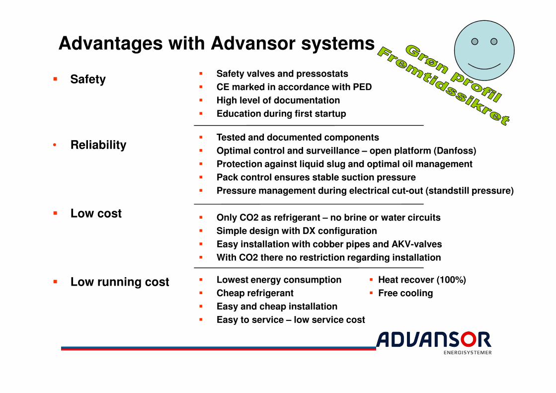
Advantages with Advansor systems
� Safety
• Reliability
� Safety valves and pressostats
� CE marked in accordance with PED
� High level of documentation
� Education during first startup
� Tested and documented components
� Optimal control and surveillance – open platform (Danfoss)
� Protection against liquid slug and optimal oil management
� Pack control ensures stable suction pressure
� Pressure management during electrical cut-out (standstill pressure)
� Only CO2 as refrigerant – no brine or water circuits
� Simple design with DX configuration
� Easy installation with cobber pipes and AKV-valves
� With CO2 there no restriction regarding installation
� Low cost
� Low running cost � Lowest energy consumption
� Cheap refrigerant
� Easy and cheap installation
� Easy to service – low service cost
� Heat recover (100%)
� Free cooling