coburn, b. h., & weaver, p. m. (2016). buckling analysis ... · pdf filecost for...
TRANSCRIPT

Coburn, B. H., & Weaver, P. M. (2016). Buckling analysis, design andoptimisation of variable-stiffness sandwich panels. International Journal ofSolids and Structures, 96, 217-228. DOI: 10.1016/j.ijsolstr.2016.06.007
Peer reviewed version
License (if available):CC BY-NC-ND
Link to published version (if available):10.1016/j.ijsolstr.2016.06.007
Link to publication record in Explore Bristol ResearchPDF-document
This is the author accepted manuscript (AAM). The final published version (version of record) is available onlinevia Elsevier at http://www.sciencedirect.com/science/article/pii/S002076831630124X. Please refer to anyapplicable terms of use of the publisher.
University of Bristol - Explore Bristol ResearchGeneral rights
This document is made available in accordance with publisher policies. Please cite only the publishedversion using the reference above. Full terms of use are available:http://www.bristol.ac.uk/pure/about/ebr-terms.html

Buckling analysis, design and optimisation of variable-stiffness sandwichpanels
Broderick H. Coburna,∗, Paul M. Weavera
aAdvanced Composites Centre for Innovation and Science, University of Bristol, Queen’s Building, Bristol BS8 1TR, UnitedKingdom
Abstract
In recent years variable-stiffness (VS) technology has been shown to offer significant potential weight sav-
ings and/or performance gains for both monolithic and stiffened plate structures when buckling is a driving
consideration. As yet, little work has been reported on VS sandwich structures. As such, a semi-analytical
model is developed based on the Ritz energy method for the buckling of sandwich panels with fibre-steered
VS face-sheets. The model captures both global and shear crimping instabilities and is shown to be ac-
curate and computationally efficient compared to commercial two- and three-dimensional finite element
analyses. Subsequent parametric and optimisation studies, which were performed for many practical ge-
ometries using the developed model, reveal that, whilst VS sandwich panels show a significant improvement
in global buckling performance, they suffer a reduction in shear crimping performance when compared to
their straight-fibre counterparts. This behaviour is found to be due to the VS face-sheets creating a pre-
buckling load redistribution where regions locally exceed the critical shear crimping load and induce the
short wavelength instability at a reduced panel level load. For VS sandwich panels with modest to low
transverse shear moduli of the core, shear crimping can become the critical mode diminishing performance
benefits relative to straight-fibre configurations. Cores with sufficient flexural rigidity, thus preventing shear
crimping, showed improvements in critical buckling load in the order of 80 % when using VS, however this
improvement reduces to a negligible amount with decreasing core transverse shear moduli. The transverse
shear flexibility and load redistribution are thus two key parameters that must be considered carefully in the
design of sandwich panels, in order to exploit the benefits of VS fully in this novel structural configuration.
Keywords: Fibre-steering, Ritz method, Shear crimping, Transverse shear, Variable-angle tow
1. Introduction
Traditional tailoring of fibre-reinforced composites is achieved by varying the orientation of fibres through
the thickness of a laminate. However, recent advancements of automated fibre placement (AFP) and tape
∗Corresponding authorEmail address: [email protected] (Broderick H. Coburn)
Preprint submitted to International Journal of Solids and Structures April 17, 2016

laying technologies have led to the possibility of steering fibres in the plane of a ply, thus creating variable-
stiffness laminates and significantly increasing the design space available to engineers. In recent times,
performance benefits of VS laminates have been shown for: the buckling and post-buckling of plates [1–7],
shells [8] and stiffened panels [9–11]; the stress distribution around discontinuities [12, 13]; and stiffness
blending of structures [14, 15]. The manufacture of VS laminates has been achieved largely through the
established AFP [14] and lately through an early concept manufacturing method called continuous tow
shearing [16, 17].
The majority of work to date on the buckling of VS structures is limited to simple configurations,
such as plates and shells, with simple boundary conditions. Whilst analytical and semi-analytical methods
[1, 2, 4] provide an accurate and computationally efficient alternative to finite element analysis (FEA),
they are often limited to simple cases in terms of loading, boundary conditions, geometry and structural
configuration. Recently, Coburn et al. [9, 10] developed an analytical model based on the Ritz energy
method for the buckling of stiffened VS panels including a first-order shear deformation theory (FSDT)
to enable the study of thick laminate sections. Using the model in a follow-up optimisation study [11], it
was shown that stiffened VS panels can achieve mass reductions when compared to straight-fibre stiffened
panels, albeit to a lesser extent than plates considered in isolation [1, 3, 4, 18].
One application of VS that has not been explored to date, to the best of the authors’ knowledge, is
the use of fibre-steering in composite face-sheets to create VS sandwich panels. Sandwich panels are well
known to be efficient structures in bending and buckling and for this reason are commonly used in regions
where supported edges are spaced far apart. The aim of this work is to use the approach presented by
Coburn et al. [10], including a FSDT in a semi-analytical Ritz model, to explore structural configurations
of VS sandwich panels and the effect of fibre-steering and core shear flexibility on buckling performance. In
particular, the study will focus on translating the case identified by Gurdal and co. [1, 18], who showed that
a simply-supported square plate subject to uniform end-shortening can achieve up to 80 % improvement in
critical buckling load with a lateral direction fibre path variation, to sandwich panels. We found that the
simple FSDT was of sufficient fidelity to understand and explain the response of the sandwich panels we
consider. Future work could consider development of models, such as that recently developed by Groh and
Weaver [19], which could represent the behaviour of more general sandwich panels that could be thicker or
have more complex boundary conditions and loading.
The following sections are structured as follows: Section 2 develops a two-dimensional semi-analytical
model for the buckling analysis of VS sandwich panels subject to uniaxial and biaxial loading with clamped
and simply-supported boundary conditions applying a FSDT; a parametric study is then performed in
Section 3 on the fibre angle variation for panels with various core properties, followed by a discussion of the
failure modes and significance of core shear stiffness; in Section 4, an optimisation study with an increased
variation in fibre-steering is performed identifying optimal configurations and improvements; and finally, the
2

paper is concluded in Section 5.
2. Semi-analytical model
The semi-analytical model considers uniaxial and biaxial loading of a prismatic sandwich panel with
fibre-steering in the lateral direction (y-direction). Previous studies on VS plates [18] indicate that a one-
dimensional variation, perpendicular to the principal loading direction leads to a favourable redistribution of
loads towards supported boundaries, improving the global buckling performance and additionally allowing
manufacturable fibre paths. The extension of the model to fibre paths varying in the longitudinal direction
or in-plane shear loading could be achieved with the use of a more generalised Airy stress function and the
pre-buckling boundary conditions as detailed in Wu et al. [20].
Transverse shear strains are included in the analysis with a through thickness weighted average approach,
as is typically the case with a FSDT. FSDTs [21–23] can provide accurate solutions with low computational
cost for moderately thick plates and have previously been incorporated into the buckling analysis of thick
plates and sandwich structures by applying the Ritz method and assuming additional shape functions for
either rotation or transverse shear strain profiles [24–26]. Smearing properties and idealising the three-
dimensional structure in two-dimensions, the FSDT is suitable for predicting global events such as buckling.
For structures exhibiting large variations in stiffness through the thickness, such as sandwich panels, care
must be taken when interpreting results obtained from a FSDT. It is acknowledged that for characteristic
length to thickness ratios less than typically 20:1, or the requirement for detailed through thickness stresses,
the FSDT approach detailed herein could be insufficient and higher-order shear deformation theories or
full three-dimensional analyses would be required. The characteristic length of a panel, for the purposes
of buckling analyses, is the dimension which drives the size of the buckling half-waves. For the case of
long panels with edges free to expand, as is the case for the parametric and optimisation studies presented
herein, this is typically the panel’s shorter transverse dimension. The characteristic length to thickness
ratio provides a rule-of-thumb guide to the importance of through-thickness behaviour, as the characteristic
length is a measure of the length over which a buckled half-wave occurs. Thus a more appropriate value for
characteristic length, would therefore be the shortest dimension of the buckling half-waves that form, this
however requires knowledge of the solution, and for pre-analysis guidance, appropriate panel dimension are
therefore commonly used.
In this study the semi-analytical model was implemented in MATLAB R2013a [27].
2.1. Sandwich panel description and loading
The sandwich panel considered consists of two identical VS composite face sheets, individually con-
strained to be balanced and symmetric about their local geometric midplane (B, A16, A26 = 0), either side
3
b
a
Δx/2
Δy/2Core
VS face-sheets
Variable fibre path (y-direction)
yz
xy
zx
Δx/2
Δy/2
Reference planeyz
b
a
Δx/2
Δy/2Core
VS face-sheets
Variable fibre path (y-direction)
yz
xy
zx
Δx/2
Δy/2
T1
T1
T22D thick plate
idealisation
ICCM20
yz
x
Core
VS face-sheets
Variable fibre path (y-direction)
yz
x
T1
T1
T2
b
a
Δx/2
Δy/2
yz
x
Δx/2
Δy/2
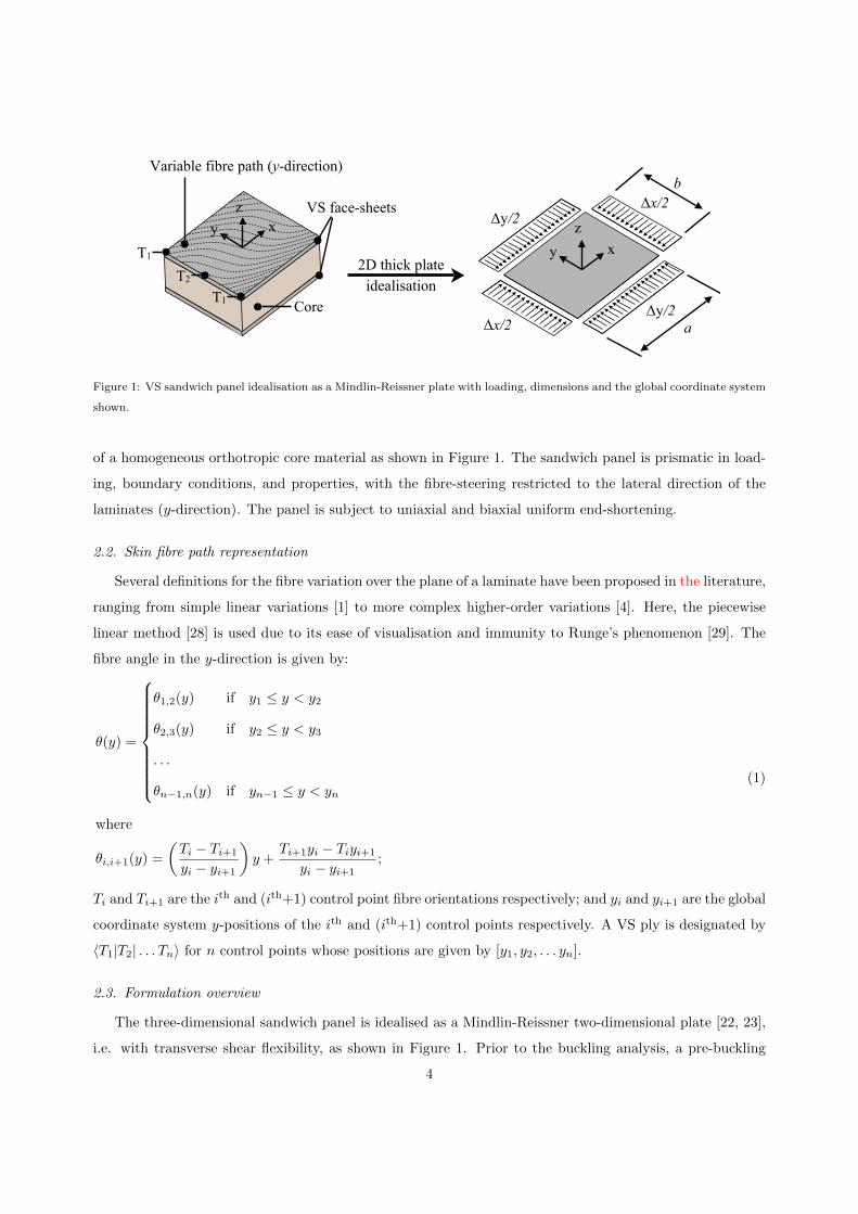
Figure 1: VS sandwich panel idealisation as a Mindlin-Reissner plate with loading, dimensions and the global coordinate system
shown.
of a homogeneous orthotropic core material as shown in Figure 1. The sandwich panel is prismatic in load-
ing, boundary conditions, and properties, with the fibre-steering restricted to the lateral direction of the
laminates (y-direction). The panel is subject to uniaxial and biaxial uniform end-shortening.
2.2. Skin fibre path representation
Several definitions for the fibre variation over the plane of a laminate have been proposed in the literature,
ranging from simple linear variations [1] to more complex higher-order variations [4]. Here, the piecewise
linear method [28] is used due to its ease of visualisation and immunity to Runge’s phenomenon [29]. The
fibre angle in the y-direction is given by:
θ(y) =
θ1,2(y) if y1 ≤ y < y2
θ2,3(y) if y2 ≤ y < y3
. . .
θn−1,n(y) if yn−1 ≤ y < yn
where
θi,i+1(y) =
(Ti − Ti+1
yi − yi+1
)y +
Ti+1yi − Tiyi+1
yi − yi+1;
(1)
Ti and Ti+1 are the ith and (ith+1) control point fibre orientations respectively; and yi and yi+1 are the global
coordinate system y-positions of the ith and (ith+1) control points respectively. A VS ply is designated by
〈T1|T2| . . . Tn〉 for n control points whose positions are given by [y1, y2, . . . yn].
2.3. Formulation overview
The three-dimensional sandwich panel is idealised as a Mindlin-Reissner two-dimensional plate [22, 23],
i.e. with transverse shear flexibility, as shown in Figure 1. Prior to the buckling analysis, a pre-buckling
4
analysis is required to determine the non-uniform stress resultant distribution in the VS structure when
subject to uniform end-shortening. This is achieved using the approach of Wu et al. [4], albeit for the
simpler prismatic case, by formulating the total complementary energy of the system and solving for the
unknown Airy stress function with the Ritz method. For the buckling analysis, the total potential energy
of the panel is given by contributions from the bending energy, transverse shear energy, and external work,
and expressed as functions of the out-of-plane displacement and transverse shear strains. Applying the Ritz
method by minimising the total potential energy yields an eigenvalue problem whose eigenvectors are the
buckling modes.
2.4. Stiffness matrices
For sandwich panels consisting of identical face-sheets and a core material (see Figure 1), the A-, B-,
D-stiffness matrices about the global midplane are given by:
A = 2Afs + Ac, B = 0, and
D = 2Dfs +(hfs + hc)
2
2Afs + Dc,
(2)
where h is a thickness, and the subscripts fs and c indicate a single face-sheet and the core respectively. The
A-matrix represents the extensional stiffness of the panel that relates in-plane forces to in-plane deformations,
the B-matrix represents the in-plane-out-of-plane coupling stiffness of the panel that relates in-plane forces
to curvatures, and moments to in-plane deformations, and the D-matrix represents the flexural stiffness
of the panel that relates moments to curvatures. Owing to the varying fibre orientation of the face-sheets
all stiffness matrix terms are variable in the y-direction. The smeared transverse shear stiffness terms are
determined using the approach detailed in Kollar and Springer [30] where the face-sheets are assumed to
be thin, i.e. negligible stiffness in bending about their own midplane, and have a high transverse shear
stiffness compared to the thick core. The resulting transverse shear stress profile in the z-direction under
these assumptions consists of a large and approximately constant transverse shear stress in the thick core
region which ramps down, approximately linearly, in the thin skins to zero at the upper and lower surfaces
[31]. Assuming the transverse shear deformation to be negligible in the face-sheets (high transverse shear
stiffness) and constant in the core, the equivalent transverse shear stiffness of the sandwich plate can be
given solely by core stiffness properties as:
Hij = heQc,ij where he =(hfs + hc)
2
hc(3)
and is the equivalent core thickness for transverse shear rigidity purposes, i, j = 4, 5, and Qc,ij is the core
stiffness matrix in the global coordinate system. For an orthotropic sandwich core, as is most commonly
the case for foam and honeycomb constructions, the stiffness matrix in the local coordinate system, Qc, is
5
given by:
Qc =
Qc,44 Qc,45
Qc,54 Qc,55
=
Cc,44 Cc,45
Cc,54 Cc,55
=
Gc,23 0
0 Gc,13
. (4)
Full explanations of all stiffness and transformation matrices can be found in Reference [30]. Ultimately,
the assumptions made in the derivation of the smeared transverse shear stiffnesses for the sandwich panel
limit the applicability of the model to skins which are thin and stiff in transverse shear relative to the core
material. The use of thick skins would require the consideration of parabolic stress profiles in both the
skins and core, whilst the use of shear flexible skins would invalidate the assumption of null transverse shear
deformation in the skins. Therefore, sufficient care should thus be taken when using this approach outside
of our assumptions.
2.5. Pre-buckling
Two pre-buckling load cases are considered; in both cases the lateral edges are subject to a uniform
end-shortening of ∆x in the x-direction, with case A allowing longitudinal edges to expand, and case B
additionally applying an end-shortening of ∆y in the y-direction to create a biaxial stress state as shown
in Figure 1. In both cases, all edges are free to translate parallel to the edge direction and the panel is
constrained to have null Ai6 (i = 1, 2) extension-shear coupling terms resulting in either a purely uniaxial
or biaxial stress state.
2.5.1. Total complementary energy
The energy of the system for pre-buckling is formulated as the total complementary energy extending
the approach of Wu et al. [20] who found that utilising the Ritz method for the pre-buckling problem of
VS plates with prescribed edge displacements was intractable with the total potential energy. The total
complementary energy of a plate subject to prescribed edge displacements is given by [20, 32]:
Πc =1
2
∫∫S
[a11
(∂2Φ
∂y2
)2
+ 2a12∂2Φ
∂x2∂2Φ
∂y2+ a22
(∂2Φ
∂x2
)2
+ a66
(∂2Φ
∂x∂y
)2
− 2a16∂2Φ
∂y2∂2Φ
∂x∂y− 2a26
∂2Φ
∂x2∂2Φ
∂x∂y
]dy dx
−∫ b/2
−b/2
[∂2Φ
∂y2u− ∂2Φ
∂x∂yv
]x=a/2
dy
+
∫ b/2
−b/2
[∂2Φ
∂y2u− ∂2Φ
∂x∂yv
]x=−a/2
dy
−∫ a/2
−a/2
[∂2Φ
∂x2v − ∂2Φ
∂x∂yu
]y=b/2
dx
+
∫ a/2
−a/2
[∂2Φ
∂x2v − ∂2Φ
∂x∂yu
]y=−b/2
dx,
(5)
6

where: aij (i, j = 1, 2, 6) are the terms of the inverse of the in-plane stiffness matrix A; u and v are the
displacements in the x- and y-directions respectively; S is the surface of the plate; and Φ is the Airy stress
function defined as:
Nx =∂2Φ
∂y2, Ny =
∂2Φ
∂x2and Nxy = − ∂2Φ
∂x∂y, (6)
where Nx, Ny and Nxy are the in-plane stress resultants. The analysis is further simplified and generalised
by expressing the total complementary energy in the normalised coordinate system of ξ and η with:
ξ =2x
aand η =
2y
b. (7)
2.5.2. Shape functions
Owing to the panel being prismatic the Ny stress resultant is constant over the entire domain and can
be captured with a single term. By constraining the panel to have no extension-shear coupling or shear
loading the Nxy stress resultant is null over the entire domain. The only variable stress resultant requiring
representation with a series expansion is Nx which varies in the y-direction. The Airy stress function, in the
normalised coordinate system (Equation 7), can therefore be represented as a polynomial series expansion
given by:
∂2Φ
∂η2=b2
4Nx =
H∑h=1
[chLh−1(η)] = chLh−1
and
∂2Φ
∂ξ2=a2
4Ny = d0,
(8)
where Lh−1 is the polynomial series in the y-direction, H the number of terms in the Lh−1 series, and ch the
unknown coefficients. The variation in the y-direction, chLh−1, is free at boundaries, with a Legendre poly-
nomial series chosen for the Lh−1 shape function. The use of polynomial series’ enables the highly localised
behaviour, present in VS structures, to be captured well due to the non-periodic nature of polynomials [4].
The total complementary energy of the system can then be expressed in terms of the unknowns, ch and d0,
by substituting the shape functions, Equation 8, into the normalised form of Equation 5.
2.5.3. Principle of stationary complementary energy
Applying the principle of stationary complementary energy, δΠc = 0, which is mathematically identical
to the principle of stationary potential energy for linear systems, to the non-dimensional form of the total
complementary energy and minimising with respect to the unknown coefficients results in a set of linear
equations, which, expressed in matrix form, are given by:Ucc Ucd0
UTcd0
Ud0d0
c
d0
=
Px0
Py0
, (9)
7

where, for example; Ucd0 is the stiffness matrix of the c coefficients obtained when minimising the total
complementary energy of the system with respect to the d0 coefficient; Px0 and Py0 are the constants that
arise when minimising the total complementary energy with respect to c and d0 respectively; and c and
d0 a vector and scalar of the unknown coefficients respectively. The solution to the problem of Equation 9
yields the coefficients of the Airy stress function which enables the stress resultant field under the prescribed
loading to be determined as per Equation 6.
2.6. Buckling
The Ritz method is used on the total potential energy to solve the buckling problem for the panel
using the stress resultant distribution obtained in the pre-buckling analysis. The plate is loaded by the end-
shortening ∆x for pre-buckling case A and [∆x,∆y] for pre-buckling case B which is increased proportionally
by a loading parameter, λ.
2.6.1. Total potential energy
The total potential energy of the panel is given by the sum of the bending strain energy, UD; transverse
shear strain energy, UH; and external work, T , by:
Π = UD + UH + T, (10)
where for a Mindlin-Reissner plate UD, UH and T are given by [30]:
UD =1
2
∫ a/2
−a/2
∫ b/2
−b/2
[D11
(∂2w
∂x2− ∂γxz
∂x
)2
+D22
(∂2w
∂y2− ∂γyz
∂y
)2
+2D12
(∂2w
∂x2− ∂γxz
∂x
)(∂2w
∂y2− ∂γyz
∂y
)+D66
(2∂2w
∂x∂y− ∂γxz
∂y− ∂γyz
∂x
)2
+2D16
(∂2w
∂x2− ∂γxz
∂x
)(2∂2w
∂x∂y− ∂γxz
∂y− ∂γyz
∂x
)+2D26
(∂2w
∂y2− ∂γyz
∂y
)(2∂2w
∂x∂y− ∂γxz
∂y− ∂γyz
∂x
)]dy dx,
(11)
UH =1
2
∫ a/2
−a/2
∫ b/2
−b/2
[H55γ
2xz + 2H45γxzγyz +H44γ
2yz
]dy dx (12)
and
T =λ
2
∫ a/2
−a/2
∫ b/2
−b/2
[Nx
(∂w
∂x
)2
+Ny
(∂w
∂y
)2
+2Nxy
(∂w
∂x
∂w
∂y
)]dy dx
(13)
8
respectively, where: Dij (i, j = 1, 2, 6) are the terms of the bending stiffness matrix, D; Hij (i, j = 4, 5) are
the terms of the transverse shear stiffness matrix, H; w is the out-of-plane displacement; and γxz and γyz
are the transverse shear strains in the xz- and yz-directions respectively. The analysis is further simplified
and generalised by expressing the total potential energy in the normalised coordinate system of ξ and η
(Equation 7).
2.6.2. Shape functions
The shape functions for the out-of-plane displacement and transverse shear strain in the xz- and yz-
directions are given by:
w =
M∑m=1
N∑n=1
[AmnXm(ξ)Yn(η)] = AmnXmYn,
γxz =
F∑f=1
G∑g=1
[DfgFf (ξ)Gg(η)] = DfgFfGg,
and
γyz =
K∑k=1
L∑l=1
[EklKk(ξ)Ll(η)] = EklKkLl,
(14)
respectively, where: for the w shape function, Xm and Yn are polynomial series in the x- and y-directions
respectively, M and N are the number of terms in the Xm and Yn series respectively and Amn are the
unknown coefficients; for the γxz shape function, Ff and Gg are polynomial series in the x- and y-directions
respectively, F and G are the number of terms in the Ff and Gg series respectively and Dfg are the
unknown coefficients; and for the γyz shape function, Kk and Ll are polynomial series in the x- and y-
directions respectively, K and L are the number of terms in the Kk and Ll series respectively and Ekl are
the unknown coefficients.
A summary of the required shape function boundary conditions for w, γxz and γyz for given edge
boundary conditions are provided in Table 1. The required boundary conditions are implemented through
circulation functions applied to the Legendre polynomials [4, 11] in the form:
Xi(ξ) = Γx(ξ)
I∑i=1
Li−1(ξ) where Γx(ξ) = (ξ − ξc)n , (15)
and the circulation function, Γx(ξ), enforces a condition at ξ = ξc by setting: n = 0 for a free condition;
n = 1 for a simply-supported condition (Xi = 0); and n = 2 for clamped condition (Xi, ∂Xi/∂ξ = 0).
The total potential energy of the system can then be expressed in terms of the unknowns Amn, Dfg
and Ekl by substituting the shape functions (Equation 14) into the normalised form of Equations 10-13 and
performing numerical integration.
9

Boundary condition
Direction Description w γxz γyz
x-directionSimply-supported S-S F-F S-S
Clamped C-C S-S S-S
y-directionSimply-supported S-S S-S F-F
Clamped C-C S-S S-S
Table 1: Boundary conditions and corresponding shape function selection for out-of-plane displacement and transverse shear
strains. F: Free (n = 0); S: Simply-supported (n = 1); C: Clamped (n = 2).
2.7. Principle of stationary potential energy
Applying the principle of stationary potential energy, δΠ = 0, to the non-dimensional form of the total
potential energy and minimising with respect to the unknown coefficients, Amn, Dfg and Ekl, results in a
set of linear equations which expressed in matrix form are given by:KAA KAD KAE
KTAD KDD KDE
KTAE KT
DE KEE
− λLAA 0 0
0 0 0
0 0 0
Amn
Dfg
Ekl
=
0
0
0
, (16)
where, for example: KAD is the stiffness matrix of the A coefficients obtained when minimising the strain
energy of the system with respect to the D coefficient; LAA the geometric stiffness matrix; and Amn, Dfg
and Ekl the vectors of the unknown coefficients.
The solution to the eigenvalue problem of Equation 16 yields stationary points in the total potential
energy which are buckling modes of the panel. The eigenvectors provide the coefficients of the out-of-plane
displacement and transverse shear strain shape functions, whilst the eigenvalue, λ, the load multiplier of the
input uniform end-shortening.
3. Parametric study
The parametric study is performed on a long sandwich panel allowing several buckled half-waves to form
in the longitudinal direction. As identified by Gurdal and co. [1, 18], the performance benefits associated
with thin plates with fibre-steering in the lateral direction extend from square plates to long plates, the use
of a long panel herein somewhat removes the dependency of lateral edge boundary conditions. The sandwich
panel is 1000 mm long, 400 mm wide, with an 8 mm core and 1 mm face-sheets consisting of eight plies of
IM7/8552 (E11 = 161 MPa, E22 = 11.38 MPa, G12 = 5.17 MPa, ν12 = 0.32, tply = 0.125 mm). Whilst
the characteristic length to thickness ratio of these panels is relatively high, i.e. 40:1, taking the shorter
in-plane dimension which drives the buckling mode shape (refer to Section 2), sandwich panels are typically
10

Table 2: Core materials and corresponding transverse shear stiffness used in the parametric study [33, 34].
Core Gc [MPa]
1 No shear flexibility ∞
2 High density aluminium honeycomb / 1000
syntactic foam
3 Medium density aluminium honeycomb 500
4 Low density aluminium honeycomb 200
5 High density aramid honeycomb / 100
low density aluminium honeycomb
6 Low density aramid honeycomb 10
used in regions where enhanced structural efficiency, in terms of bending and buckling, is required due to
large distances between supported boundaries. Furthermore, transverse shear effects become significant in
composite sandwich panels at much lower thickness to characteristic length ratios than monolithic composites
due to the high ratio of in-plane stiffness to transverse shear stiffness present in sandwich panels [5].
The critical buckling load was determined for the case of uniform end-shortening with longitudinal edges
free to expand and all edges simply-supported. The VS skin is achieved with a linear variation in the y-
direction symmetric about the centre line of the panel (y=0) in the form [±〈T1|T2〉2]s, where T1 and T2 are
located at the edge and centre line of the panel, i.e. y1=b/2 and y2=0 respectively, as shown in Figure 1.
Six different isotropic core properties were considered as detailed in Table 2, all representing practical values
ranging from high density aluminium honeycomb, or syntactic foam, to low density aramid honeycomb
[33, 34].
It should be noted, that sandwich panels can fail through a variety of mechanisms including: material
strength of either the face-sheets or core; and various instabilities such as intra-cell dimpling, face wrinkling,
shear crimping, and global buckling. The focus of this study, however, is on global instabilities present when
idealising the structure as a thick two-dimensional plate, i.e. global buckling and shear crimping. Strength
based failure modes, as well as intra-cell dimpling and face wrinkling, are not captured or discussed further.
To enable observation of the qualitative effect of the core’s shear stiffness, the core’s contribution to
axial and bending stiffnesses of the panel is neglected. For sandwich panels, the overall in-plane and flexural
stiffnesses are often dominated by skin properties alone and in-plane properties of the core, such as Poisson’s
ratio and Young’s modulus, do not affect buckling behaviour or loads to any great extent.
For VS structures, it is convenient to present the stiffness and buckling loads as smeared (or averaged)
values due to their non-uniformity, which for the pre-buckling stiffness and critical buckling load are given
11

by:
Ex,sm =a
bh∆x
∫ b/2
−b/2
[Nx(y)|x=−a/2
]dy, (17)
and
Nx,sm =1
b
∫ b/2
−b/2
[Nx(y)|x=−a/2
]dy, (18)
respectively. The pre-buckling stiffness and critical buckling load were obtained for every combination
of angle for T1 and T2 varying from 0◦ to 90◦ in 5◦ increments for all core values provided in Table 2.
However, as an introduction to the form of plots used to present the results, and to serve as a baseline
comparison, results are first provided for the case of a thin 2 mm plate neglecting transverse shear effects
([±〈T1|T2〉2]2s). The normalised smeared critical buckling load is plotted against the normalised smeared
pre-buckling stiffness, given by:
Nx,sm =Nx,sm
max[Nx,sm|T1=T2
] and Ex,sm =Ex,sm
max [Ex,sm], (19)
respectively, in Figure 2. Here, the buckling load is normalised against the maximum straight-fibre configu-
ration buckling load and can be considered a VS factor of improvement, whilst the pre-buckling stiffness is
normalised against the maximum pre-buckling stiffness, which occurs for an all 0◦ straight-fibre laminate.
The data is plotted in sets of T2 angles with an additional plot for straight-fibre configurations (T1=T2).
This form of plot was first used to illustrate the design space of VS laminates for buckling by Olmedo and
Gurdal [1]. The thick dashed line is the straight-fibre configuration and the thin black lines VS which are
labelled in 15◦ increments for T2 in Figure 2. The area bound by the VS curves represents a significant
increase in design space when compared to the straight-fibre configurations. The maximum buckling load
achieved with VS occurs for a 〈15◦|80◦〉 variation and is 64 % higher than the maximum straight-fibre
buckling load which occurs at an angle of ±45◦.
The results obtained for the various transverse shear moduli sandwich panel configurations, including
transverse shear effects, are provided in Figure 3. Panels neglecting core shear flexibility (Gc = ∞MPa)
or with high core transverse shear stiffness (Gc = 1000, 500 MPa) showed similar buckling characteristics
and relative improvements over straight-fibre configurations as the thin VS plates of the same aspect ratio
provided in Figure 2, having approximately a peak improvement of 62 % for a 〈15◦|85◦〉 fibre path. How-
ever, further decreasing the core shear modulus to 200 MPa resulted in the normalised buckling plots in
Figure 3 taking a different form, with an associated reduction in improvements of VS panels when com-
pared to straight-fibre configurations; the behaviour becoming more prevalent with further reductions in
core transverse shear modulus.
The change in behaviour and loss of performance displayed in Figure 3 for panels with low shear modulus
cores are attributed to the critical buckling mode of the panel changing from global to core shear crimping,
12

0 0.5 10.3
1
1.7
Straight fibre
−75 −50 −25 0 25 50 750
0.25
0.5
0.75
1
0 5 10 150.75
0.8
0.85
0.9
0.95
15 35 55 750.12
0.14
0.16
See inset
See inset
−75 −50 −25 0 25 50 750
0.25
0.5
0.75
1
Figure 2: Normalised smeared critical buckling load against normalised smeared pre-buckling stiffness for a thin monolithic
plate with a linear fibre variation in the y-direction.
13

0 0.5 10.3
1
1.7
Norm
.crit.
buck.load,N
x,sm
Norm. pre-buck. stiff., Ex,sm
← 〈15◦|85◦〉, +62 %
(a) Core 1, Gc =∞.
0 0.5 10.3
1
1.7
Norm
.crit.
buck.load,N
x,sm
Norm. pre-buck. stiff., Ex,sm
← 〈15◦|85◦〉, +61 %
(b) Core 2, Gc = 1000 MPa.
0 0.5 10.3
1
1.7
Norm
.crit.
buck.load,N
x,sm
Norm. pre-buck. stiff., Ex,sm
← 〈15◦|80◦〉, +62 %
(c) Core 3, Gc = 500 MPa.
0 0.5 10.3
1
1.7Norm
.crit.
buck.load,N
x,sm
Norm. pre-buck. stiff., Ex,sm
← 〈25◦|60◦〉, +42 %
(d) Core 4, Gc = 200 MPa.
0 0.5 10.3
1
1.7
Norm
.crit.
buck.load,N
x,sm
Norm. pre-buck. stiff., Ex,sm
← 〈30◦|45◦〉, +21 %
(e) Core 5, Gc = 100 MPa.
0 0.5 10.3
1
1.7
Norm
.crit.
buck.load,N
x,sm
Norm. pre-buck. stiff., Ex,sm
7→ ±θ where θ ≤ 50◦, +0 %
(f) Core 6, Gc = 10 MPa.
Figure 3: Normalised smeared critical buckling load against normalised smeared pre-buckling stiffness for various sandwich core
shear moduli. Thin continuous lines are for fixed central angle, T2 with variable T1, and dashed lines indicate straight-fibre
configurations (T1 = T2).
14

(a) Global buckling mode. (b) Shear crimping buckling mode.
Figure 4: One-dimensional sandwich panel buckling modes.
as shown in Figures 4a and Figure 4b respectively for a one-dimensional case. This can be best explained
by examining a single curve; the profile for core five (Gc = 100 MPa) with VS [±〈T1|45◦〉2]s skins (T2 fixed
at 45◦) obtained by varying T1 from 0◦ to 90◦ in 5◦ increments is provided in Figure 5b, showing both global
and shear crimping buckling loads. With increasing pre-buckling stiffness, by varying T1 from 90◦ towards
0◦, the buckling load of the panel initially increases with critical modes being global, occurring over the
full width of the panel with two to five half-waves in the x-direction. This increase in critical buckling load
continues until a maximum absolute critical buckling load of 0.710 kN/mm at a fibre path of 〈30◦|45◦〉 is
reached, 21 % higher than the best straight-fibre configuration. Further decreasing T1 beyond 30◦ results in
an abrupt decrease in critical buckling load accompanied by a change in the buckling mode to shear crimping
occurring in localised regions towards boundary supports. Shear crimping modes continue to occur with
decreasing T1 until a configuration of 〈10◦|45◦〉 at which global modes again become critical.
Core shear crimping instabilities are short wavelength buckling modes in which displacements are pre-
dominately due to transverse shearing, rather than rotation, and are attributed to a low core shear modulus.
The local load at which crimping occurs is almost independent of skin properties and for a uniaxially loaded
sandwich panel with straight-fibre face-sheets, the critical shear crimping load is given by Vinson [35] as:
Ncrimp = Gchc. (20)
Equation 20 is applicable to sufficiently long and wide panels such that the short-wavelength crimping mode
is unaffected by boundary conditions. In the derivation, Vinson [35] additionally assumed very thin face-
sheets, i.e. the depth of the core can be equated to the distance between the midplane of the face-sheets, when
determining the equivalent transverse shear rigidity, and thus Equation 20 can provide underestimations for
face-sheets of practical thicknesses. An improvement to Equation 20 is to assume only thin face-sheets, i.e.
the depth of the core cannot be equated to the distance between the midplane of the face-sheets, and use
an equivalent core thickness for determining the transverse shear rigidity as applied in Equation 3, i.e.
Ncrimp = Gche where he =(hfs + hc)
2
hc. (21)
Equation 21 provides an increase in the panel’s transverse shear rigidity and consequently its critical shear
crimping loads. In the case of very thin face-sheets, Equations 20 and 21 yield the same results, however for
all panels considered in this chapter (hc = 8 mm, hfs = 1 mm) the shear rigidity of the modified approach,
15
Nx(y)/
Nx,sm
Lateral position, y [mm]
−200 −100 0 100 2000
0.5
1
1.5
2
2.5
〈90◦|45◦〉
〈45◦|45◦〉
〈30◦|45◦〉
〈20◦|45◦〉
〈0◦|45◦〉
Peak
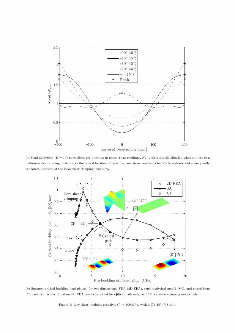
(a) Semi-analytical (H = 10) normalised pre-buckling in-plane stress resultant, Nx, y-direction distribution when subject to a
uniform end-shortening. ∗ indicates the lateral location of peak in-plane stress resultants for VS face-sheets and consequently
the lateral location of the local shear crimping instability.
0 5 10 15 200.3
0.4
0.5
0.6
0.7
0.8
0.9
1
1.1
0 5 10 15 200.3
0.4
0.5
0.6
0.7
0.8
0.9
1
1.1
Core shearcrimping
Global
Criticalpath
Core Shear Crimping
Global
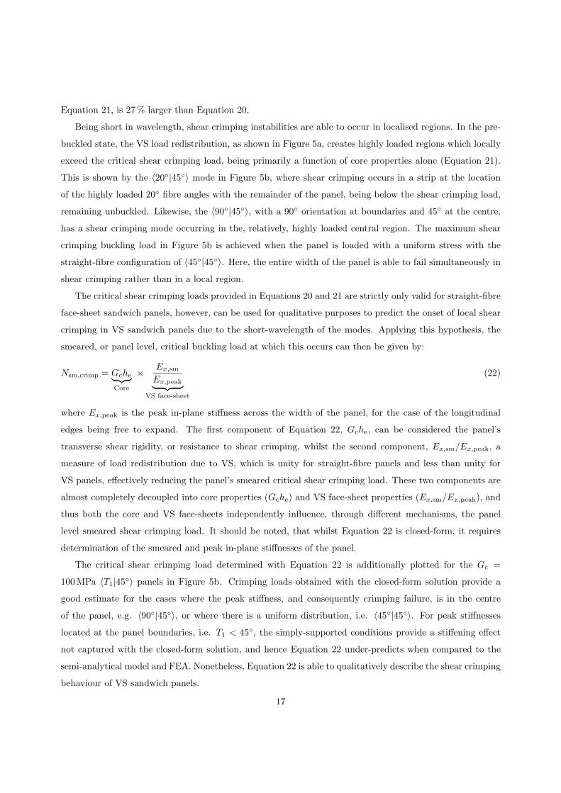
(b) Smeared critical buckling load plotted for two-dimensional FEA (2D FEA), semi-analytical model (SA), and closed-form
(CF) solution as per Equation 22. FEA results provided for critical path only, and CF for shear crimping modes only.
Figure 5: Low shear modulus core five, Gc = 100 MPa, with a 〈T1|45◦〉 VS skin.
16
Equation 21, is 27 % larger than Equation 20.
Being short in wavelength, shear crimping instabilities are able to occur in localised regions. In the pre-
buckled state, the VS load redistribution, as shown in Figure 5a, creates highly loaded regions which locally
exceed the critical shear crimping load, being primarily a function of core properties alone (Equation 21).
This is shown by the 〈20◦|45◦〉 mode in Figure 5b, where shear crimping occurs in a strip at the location
of the highly loaded 20◦ fibre angles with the remainder of the panel, being below the shear crimping load,
remaining unbuckled. Likewise, the 〈90◦|45◦〉, with a 90◦ orientation at boundaries and 45◦ at the centre,
has a shear crimping mode occurring in the, relatively, highly loaded central region. The maximum shear
crimping buckling load in Figure 5b is achieved when the panel is loaded with a uniform stress with the
straight-fibre configuration of 〈45◦|45◦〉. Here, the entire width of the panel is able to fail simultaneously in
shear crimping rather than in a local region.
The critical shear crimping loads provided in Equations 20 and 21 are strictly only valid for straight-fibre
face-sheet sandwich panels, however, can be used for qualitative purposes to predict the onset of local shear
crimping in VS sandwich panels due to the short-wavelength of the modes. Applying this hypothesis, the
smeared, or panel level, critical buckling load at which this occurs can then be given by:
Nsm,crimp = Gche︸ ︷︷ ︸Core
× Ex,sm
Ex,peak︸ ︷︷ ︸VS face-sheet
(22)
where Ex,peak is the peak in-plane stiffness across the width of the panel, for the case of the longitudinal
edges being free to expand. The first component of Equation 22, Gche, can be considered the panel’s
transverse shear rigidity, or resistance to shear crimping, whilst the second component, Ex,sm/Ex,peak, a
measure of load redistribution due to VS, which is unity for straight-fibre panels and less than unity for
VS panels, effectively reducing the panel’s smeared critical shear crimping load. These two components are
almost completely decoupled into core properties (Gche) and VS face-sheet properties (Ex,sm/Ex,peak), and
thus both the core and VS face-sheets independently influence, through different mechanisms, the panel
level smeared shear crimping load. It should be noted, that whilst Equation 22 is closed-form, it requires
determination of the smeared and peak in-plane stiffnesses of the panel.
The critical shear crimping load determined with Equation 22 is additionally plotted for the Gc =
100 MPa 〈T1|45◦〉 panels in Figure 5b. Crimping loads obtained with the closed-form solution provide a
good estimate for the cases where the peak stiffness, and consequently crimping failure, is in the centre
of the panel, e.g. 〈90◦|45◦〉, or where there is a uniform distribution, i.e. 〈45◦|45◦〉. For peak stiffnesses
located at the panel boundaries, i.e. T1 < 45◦, the simply-supported conditions provide a stiffening effect
not captured with the closed-form solution, and hence Equation 22 under-predicts when compared to the
semi-analytical model and FEA. Nonetheless, Equation 22 is able to qualitatively describe the shear crimping
behaviour of VS sandwich panels.
17

Returning focus back to Figure 3, for core six (Figure 3f) with a core shear modulus of 10 MPa, even the
slightest load variation results in local shear crimping and thus the optimal VS configurations coincide with
the straight-fibre laminates. For angles greater than 50◦ the straight-fibre configurations for core six buckle
in global modes and plateau at a constant maximum below this angle in shear crimping, as per Equation 21.
In all results presented, the semi-analytical model used 10 terms in the pre-buckling analysis whilst for
the buckling analysis a different amount of terms were used for high and low shear modulus cores, due to
the high frequency waves that occurred with shear crimping. For high shear modulus cores (cores one to
three) 15 and 9 terms (405 degrees of freedom) were used in the x- and y-directions respectively, whilst for
low modulus cores (cores four to six) 20 and 15 terms (900 degrees of freedom) were used in the x- and
y-directions respectively.
Critical buckling loads were additionally computed with ABAQUS 6.12-1 [36] for specific panels using,
firstly, two-dimensional shell elements (Figure 5b), and secondly, three-dimensional solid elements (Figure 6),
both idealisations employing a linear buckling analysis. The VS was achieved in the FEA by rotating the
local element material coordinate system, i.e. fixed fibre angle per element. Core material properties of
E11 = E22 = 6 MPa, E33 = 600 MPa, G12 = 1 MPa, G13 = G23 = 100 MPa, ν12 = 0.25, ν13 = ν23 = 0.0025
were assumed.
Two-dimensional FE results were obtained for uniaxially loaded and simply-supported VS [±〈T1|45◦〉2]s
sandwich panels as per Figure 5b. The FE model achieved converged results with 4 000 10 mm square S4R
quadrilateral shell elements (20 × 103 degrees of freedom). The FSDT employed in S4R shell elements for
ABAQUS establishes an equivalent shear factor for the sandwich panel by equating the shear strain energy
of the accurate distribution (assuming piecewise parabolic distributions in each layer) to the strain energy
with the assumed profile (constant for FSDT) [36]. Results obtained with the two-dimensional FE model are
therefore considered to be more accurate in terms of transverse shear deformation than the semi-analytical
model. The same boundary conditions that were applied to the semi-analytical model were also applied
to the two-dimensional FE model. Semi-analytical results presented in Figure 5b were within 1 % of the
two-dimensional FEA and required over an order of magnitude less degrees of freedom. An advantage of
using polynomials as the semi-analytical shape functions is their ability to allow regions to exhibit short
wavelength modes locally, capturing the shear crimping failure modes as shown in Figure 5b.
Comparison of the semi-analytical model with three-dimensional FE was performed on the same config-
uration as per the two-dimensional case that is shown in Figure 5b, with the exception of applying clamped
boundary conditions along all edges instead of simply-supported. The use of clamped boundary condi-
tions was required due to the difficulty in implementation of simply-supported boundary conditions in a
three-dimensional structure in terms of load introduction and buckling mode shapes. Clamped boundary
conditions were achieved by constraining all loaded faces to remain flat (null rotation in all directions),
with only the geometric midplane of the sandwich panel constrained in out-of-plane displacement, i.e. the
18

Mesh density −Nx,sm,crit
xy-planform Face-sheet ply Core Elms [kN/mm] Error
10 mm 1 elm. (0.125 mm) 2 elm. (4 mm) 72× 103 0.8485 1.48 %
5 mm 1 elm. (0.125 mm) 2 elm. (4 mm) 288× 103 0.8375 0.16 %
5 mm 1 elm. (0.125 mm) 8 elm. (1 mm) 384× 103 0.8367 0.07 %
5 mm 3 elm. (0.042 mm) 6 elm. (1.33 mm) 864× 103 0.8361 -
Table 3: Three-dimensional FE convergence study for Gc = 100 MPa with a 〈20|45◦〉 VS skin, subject to uniaxial loading with
all edges clamped. The critical mode was shear crimping in all cases. Percentage error is relative to the highest mesh density
configuration.
loaded edges were free to expand in the z-direction about the midplane. The mesh consisted of 288 × 103
C3D8R linear hexahedron solid elements (928 × 103 degrees of freedom). Element lengths in the plane of
the structure (x- and y-directions) were 5 mm whilst through the depth of the structure (z-direction) one
element per face-sheet ply (0.125 mm depth) and two elements (4 mm depth) for the core were used. This
mesh density was found to achieve converged results, with increases in the number of elements through
the thickness of the structure by a factor of three providing less than 0.2 % improvement in shear crimping
buckling loads as detailed in Table 3.
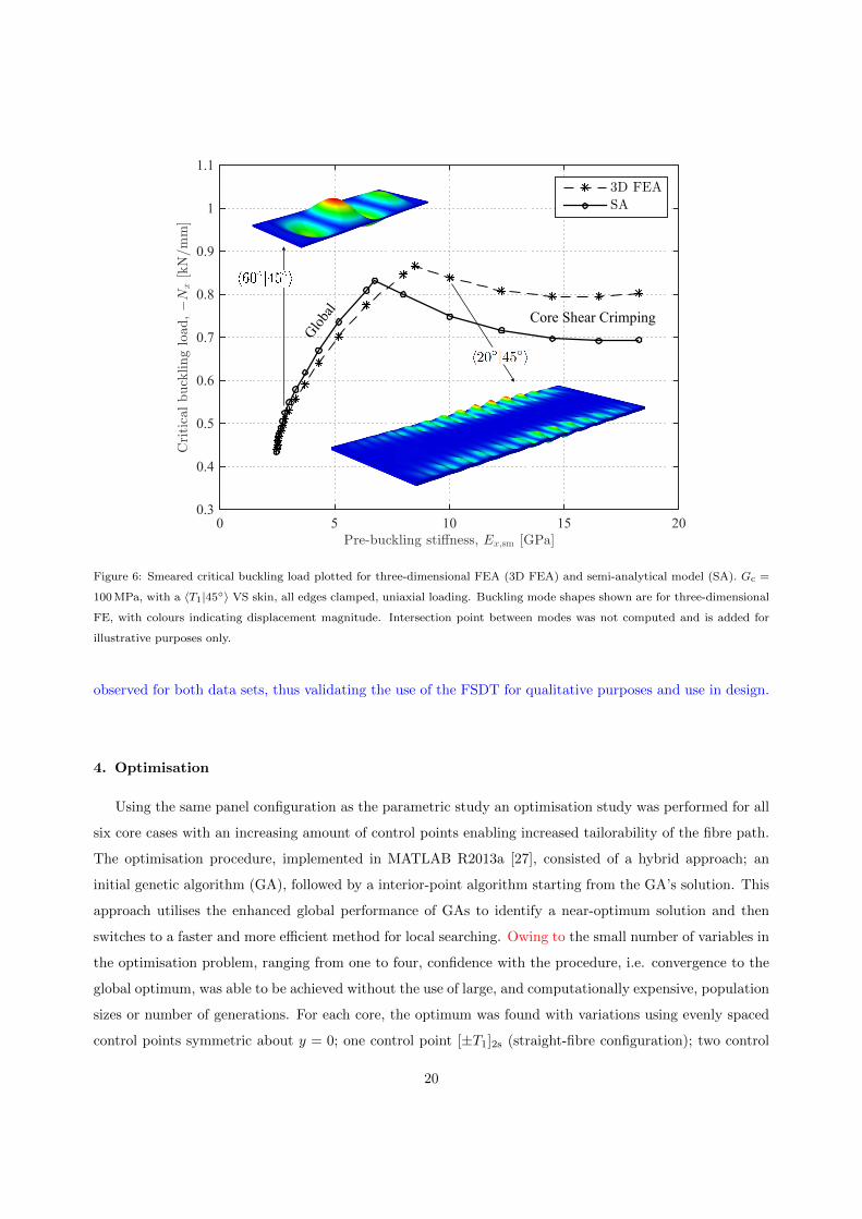
The results for the three-dimensional FE and semi-analytical model are provided in Figure 6. Three-
dimensional FE results are in good agreement with the semi-analytical for global modes, lying with within
5 % of each other, however, for shear crimping modes this error increases to 13 %. As discussed in Section 2,
the characteristic length to thickness ratio, which can be used as a rule-of-thumb guide to the importance
of through thickness behaviour, is strictly dependent on the dimension of the buckling wavelength. For all
global modes presented in Figure 6, three to four half-waves occurred in the longitudinal direction, and
one in the transverse direction, with the small dimension of the half-waves ranging from approximately
250 mm (1000 mm/4) to 333 mm (1000 mm/3), corresponding to characteristic length to thickness ratios of
25:1 (250 mm:10 mm) and 33:1 (333 mm:10 mm). For the shear crimping modes presented in Figure 6, the
size of the half-waves can be qualitatively estimated to be less than 100 mm, i.e. one quarter of the panels
width, resulting in a characteristic length to thickness ratio as low as 10:1 (100 mm:10 mm). Owing to the
high frequency mode shapes, and thus low characteristic length to thickness ratio, the shear crimping modes
are influenced to a greater extent than the large wavelength global modes with the increased modelling
of through thickness stresses and deformations. Nonetheless, at ratios of 10:1 through thickness stresses
are expected to be significant, and thus agreement within 13 % of three-dimensional FEA, considering the
simplicity of the FSDT, suggest good correlation. Furthermore, the semi-analytical model required over
three orders of magnitude less degrees of freedom than the three-dimensional FE and similar trends are
19
0 5 10 15 200.3
0.4
0.5
0.6
0.7
0.8
0.9
1
1.1
0 5 10 15 200.3
0.4
0.5
0.6
0.7
0.8
0.9
1
1.1
Core shearcrimping
Global
Criticalpath
Core Shear CrimpingGlob
al
Figure 6: Smeared critical buckling load plotted for three-dimensional FEA (3D FEA) and semi-analytical model (SA). Gc =
100 MPa, with a 〈T1|45◦〉 VS skin, all edges clamped, uniaxial loading. Buckling mode shapes shown are for three-dimensional
FE, with colours indicating displacement magnitude. Intersection point between modes was not computed and is added for
illustrative purposes only.
observed for both data sets, thus validating the use of the FSDT for qualitative purposes and use in design.
4. Optimisation
Using the same panel configuration as the parametric study an optimisation study was performed for all
six core cases with an increasing amount of control points enabling increased tailorability of the fibre path.
The optimisation procedure, implemented in MATLAB R2013a [27], consisted of a hybrid approach; an
initial genetic algorithm (GA), followed by a interior-point algorithm starting from the GA’s solution. This
approach utilises the enhanced global performance of GAs to identify a near-optimum solution and then
switches to a faster and more efficient method for local searching. Owing to the small number of variables in
the optimisation problem, ranging from one to four, confidence with the procedure, i.e. convergence to the
global optimum, was able to be achieved without the use of large, and computationally expensive, population
sizes or number of generations. For each core, the optimum was found with variations using evenly spaced
control points symmetric about y = 0; one control point [±T1]2s (straight-fibre configuration); two control
20
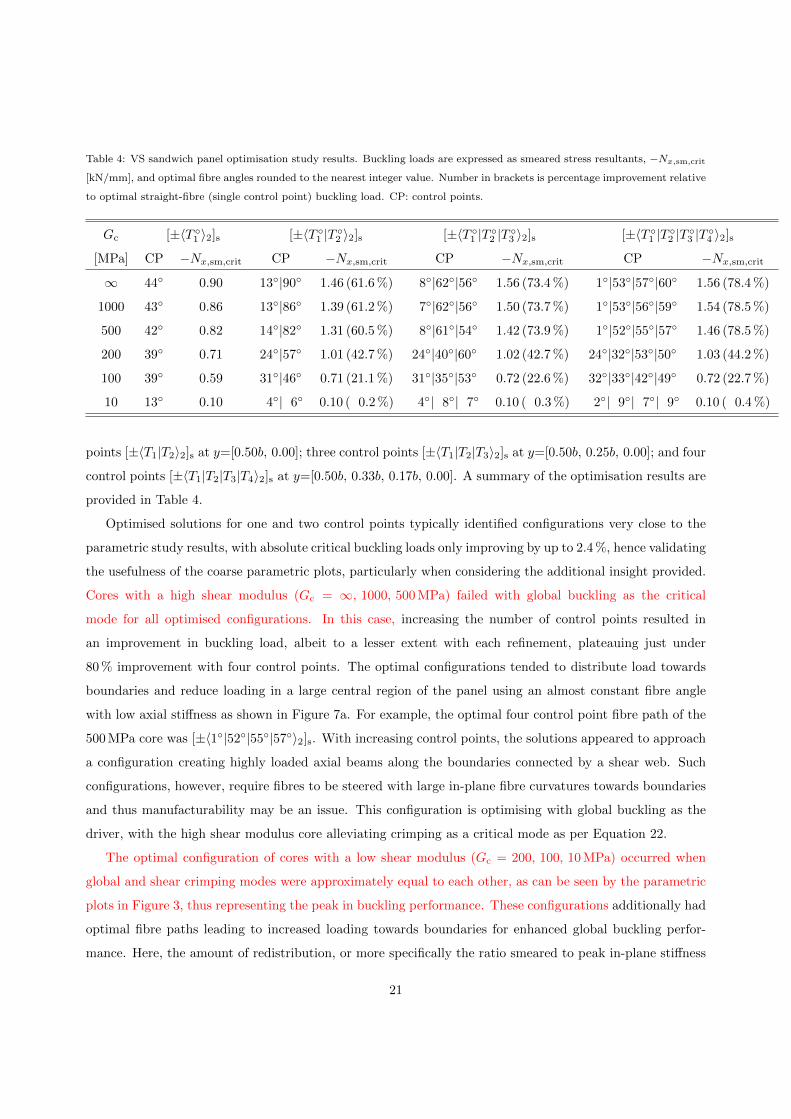
Table 4: VS sandwich panel optimisation study results. Buckling loads are expressed as smeared stress resultants, −Nx,sm,crit
[kN/mm], and optimal fibre angles rounded to the nearest integer value. Number in brackets is percentage improvement relative
to optimal straight-fibre (single control point) buckling load. CP: control points.
Gc [±〈T ◦1 〉2]s [±〈T ◦
1 |T ◦2 〉2]s [±〈T ◦
1 |T ◦2 |T ◦
3 〉2]s [±〈T ◦1 |T ◦
2 |T ◦3 |T ◦
4 〉2]s
[MPa] CP −Nx,sm,crit CP −Nx,sm,crit CP −Nx,sm,crit CP −Nx,sm,crit
∞ 44◦ 0.90 13◦|90◦ 1.46 (61.6 %) 8◦|62◦|56◦ 1.56 (73.4 %) 1◦|53◦|57◦|60◦ 1.56 (78.4 %)
1000 43◦ 0.86 13◦|86◦ 1.39 (61.2 %) 7◦|62◦|56◦ 1.50 (73.7 %) 1◦|53◦|56◦|59◦ 1.54 (78.5 %)
500 42◦ 0.82 14◦|82◦ 1.31 (60.5 %) 8◦|61◦|54◦ 1.42 (73.9 %) 1◦|52◦|55◦|57◦ 1.46 (78.5 %)
200 39◦ 0.71 24◦|57◦ 1.01 (42.7 %) 24◦|40◦|60◦ 1.02 (42.7 %) 24◦|32◦|53◦|50◦ 1.03 (44.2 %)
100 39◦ 0.59 31◦|46◦ 0.71 (21.1 %) 31◦|35◦|53◦ 0.72 (22.6 %) 32◦|33◦|42◦|49◦ 0.72 (22.7 %)
10 13◦ 0.10 4◦| 6◦ 0.10 ( 0.2 %) 4◦| 8◦| 7◦ 0.10 ( 0.3 %) 2◦| 9◦| 7◦| 9◦ 0.10 ( 0.4 %)
points [±〈T1|T2〉2]s at y=[0.50b, 0.00]; three control points [±〈T1|T2|T3〉2]s at y=[0.50b, 0.25b, 0.00]; and four
control points [±〈T1|T2|T3|T4〉2]s at y=[0.50b, 0.33b, 0.17b, 0.00]. A summary of the optimisation results are
provided in Table 4.
Optimised solutions for one and two control points typically identified configurations very close to the
parametric study results, with absolute critical buckling loads only improving by up to 2.4 %, hence validating
the usefulness of the coarse parametric plots, particularly when considering the additional insight provided.
Cores with a high shear modulus (Gc = ∞, 1000, 500 MPa) failed with global buckling as the critical
mode for all optimised configurations. In this case, increasing the number of control points resulted in
an improvement in buckling load, albeit to a lesser extent with each refinement, plateauing just under
80 % improvement with four control points. The optimal configurations tended to distribute load towards
boundaries and reduce loading in a large central region of the panel using an almost constant fibre angle
with low axial stiffness as shown in Figure 7a. For example, the optimal four control point fibre path of the
500 MPa core was [±〈1◦|52◦|55◦|57◦〉2]s. With increasing control points, the solutions appeared to approach
a configuration creating highly loaded axial beams along the boundaries connected by a shear web. Such
configurations, however, require fibres to be steered with large in-plane fibre curvatures towards boundaries
and thus manufacturability may be an issue. This configuration is optimising with global buckling as the
driver, with the high shear modulus core alleviating crimping as a critical mode as per Equation 22.
The optimal configuration of cores with a low shear modulus (Gc = 200, 100, 10 MPa) occurred when
global and shear crimping modes were approximately equal to each other, as can be seen by the parametric
plots in Figure 3, thus representing the peak in buckling performance. These configurations additionally had
optimal fibre paths leading to increased loading towards boundaries for enhanced global buckling perfor-
mance. Here, the amount of redistribution, or more specifically the ratio smeared to peak in-plane stiffness
21

(Ex,sm/Ex,peak), was limited due to crimping modes occurring. For example, the optimal four control point
fibre path of the 200 MPa core was [±〈24◦|32◦|53◦|50◦〉2]s as shown in Figure 7b. These cores tended to reach
an upper limit in improvement over straight-fibre configurations at only two control points; with this simple
linear variation seemingly a close approximation of optimal fibre paths with additional control points. The
core with a shear modulus of 10 MPa found little improvement with any fibre steering due to the minimal
core shear flexibility; promoting local shear crimping in the presence of minor load redistributions.
It should be noted, that whilst the linear buckling analysis predicts the onset of a single buckling mode,
being either global or shear crimping, mode interaction in the post-buckling regime may occur directly after
the initial buckling event. In the case of the critical mode being global, shear crimping or localised face-sheet
buckling [37] (not captured with the presented two-dimensional model) can occur. Here, the transverse shear
stresses in the core or in-plane stresses in the skin that occur in global modes can potentially promote shear
crimping or localised face-sheet buckling respectively. Similarly, if shear crimping is the critical mode, the
panel has a reduced axial load carrying capability in the region of the buckle and thus the flexural rigidity
is additionally reduced which may lead to global buckling. Experimentally, difficulty would be expected in
ascertaining which buckling mode was critical as failure may occur simultaneously, particularly if the linearly
predicted buckling modes occur at similar loads. From a design point of view, however, the prediction of
linear buckling loads for the different modes remains of importance to allow design measures to prevent each
mode occurring and provide physical insight into the structural behaviour.
5. Conclusion
In this paper, the benefits of VS sandwich panels for enhanced buckling performance were explored by
allowing face-sheet laminates to have steered fibres in the lateral direction (y-direction). A semi-analytical
Ritz model was first developed performing a pre-buckling analysis using the total complementary energy
to determine the non-uniform stress resultants, followed by a linear buckling analysis, including a FSDT,
on the total potential energy to determine buckling loads and mode shapes. Including a FSDT, the model
is able to capture both bending dominated global buckling modes, characterised by large wavelengths, and
transverse shear dominated crimping instabilities, characterised by short wavelengths.
The developed model was subsequently used in a parametric study on long uniaxially loaded and simply-
supported sandwich panels, varying both the fibre angle path along the lateral direction and core shear
modulus. Results revealed that shear crimping can occur at a significantly reduced load in VS sandwich
panels compared to their straight-fibre counterparts. For low shear modulus cores, these modes were found
to become critical, reducing the relative buckling performance of VS sandwich panels when compared to
straight-fibre configurations. For the cases considered, cores with a shear modulus of at least 500 MPa
experienced global buckling as the critical mode, with optimal VS configurations having approximately
22
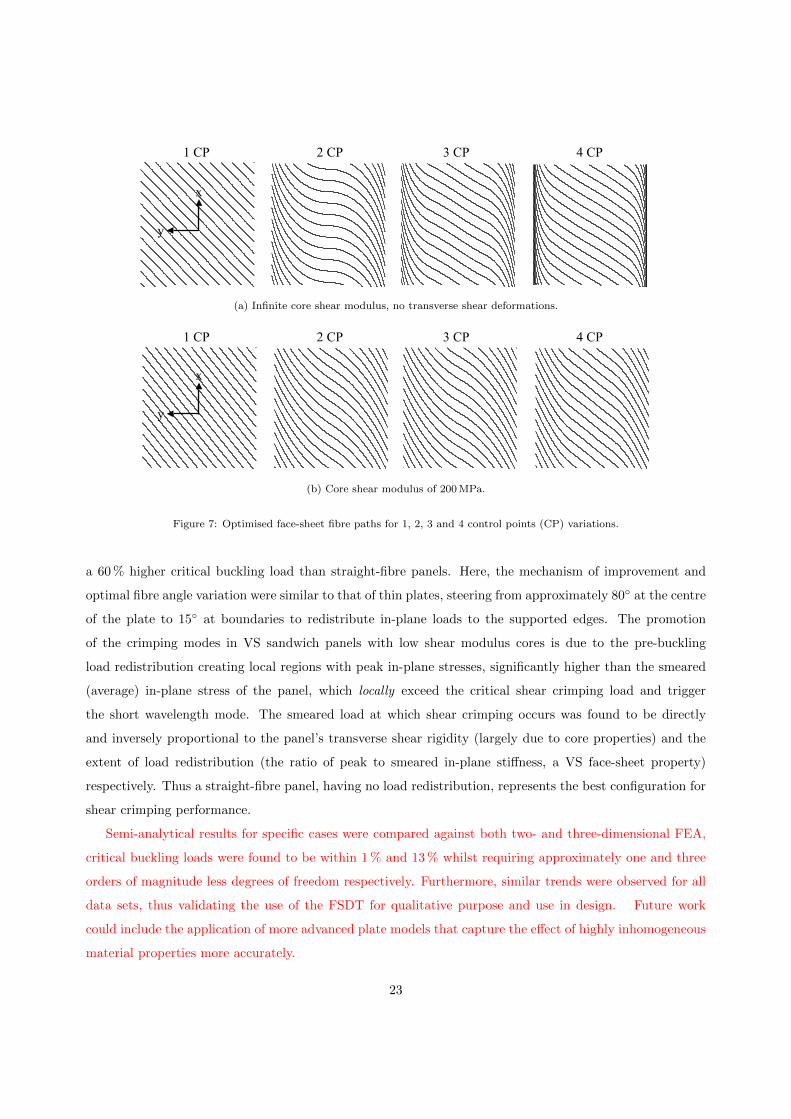
1 CP 2 CP 3 CP 4 CP
y
x
1 CP 2 CP 3 CP 4 CP
y
x
0 5 10 15 200.3
0.4
0.5
0.6
0.7
0.8
0.9
1
1.1
Core shearcrimping
Global
Criticalpath
(a) Infinite core shear modulus, no transverse shear deformations.
1 CP 2 CP 3 CP 4 CP
y
x
1 CP 2 CP 3 CP 4 CP
y
x
0 5 10 15 200.3
0.4
0.5
0.6
0.7
0.8
0.9
1
1.1
Core shearcrimping
Global
Criticalpath
(b) Core shear modulus of 200 MPa.
Figure 7: Optimised face-sheet fibre paths for 1, 2, 3 and 4 control points (CP) variations.
a 60 % higher critical buckling load than straight-fibre panels. Here, the mechanism of improvement and
optimal fibre angle variation were similar to that of thin plates, steering from approximately 80◦ at the centre
of the plate to 15◦ at boundaries to redistribute in-plane loads to the supported edges. The promotion
of the crimping modes in VS sandwich panels with low shear modulus cores is due to the pre-buckling
load redistribution creating local regions with peak in-plane stresses, significantly higher than the smeared
(average) in-plane stress of the panel, which locally exceed the critical shear crimping load and trigger
the short wavelength mode. The smeared load at which shear crimping occurs was found to be directly
and inversely proportional to the panel’s transverse shear rigidity (largely due to core properties) and the
extent of load redistribution (the ratio of peak to smeared in-plane stiffness, a VS face-sheet property)
respectively. Thus a straight-fibre panel, having no load redistribution, represents the best configuration for
shear crimping performance.
Semi-analytical results for specific cases were compared against both two- and three-dimensional FEA,
critical buckling loads were found to be within 1 % and 13 % whilst requiring approximately one and three
orders of magnitude less degrees of freedom respectively. Furthermore, similar trends were observed for all
data sets, thus validating the use of the FSDT for qualitative purpose and use in design. Future work
could include the application of more advanced plate models that capture the effect of highly inhomogeneous
material properties more accurately.
23
Applying the same loading, boundary conditions and geometry as the parametric study, an optimisation
study was performed on the sandwich panels with various core properties utilising up to a four control
point fibre variation. Optimised configurations of high modulus cores (Gc ≥ 500 MPa) had improvements
in critical buckling loads, over straight-fibre panels, of 78 % with four control points. Here, the optimal
fibre paths tended to increase pre-buckling loading towards the boundaries, with angles close to 0◦, and
rapidly reduce loading in a large central region with an almost constant fibre angle. Cores with low shear
moduli (Gc < 500 MPa), on the other hand, tended to utilise a less aggressive load redistribution, to prevent
premature shear crimping at a low panel level load, and had reduced improvements in critical buckling load
relative to straight-fibre panels. With reducing core shear modulus, the improvement decreased from 78 %
(Gc ≥ 500 MPa) to less than 1 % for a 10 MPa shear modulus core.
The transverse shear flexibility and load redistribution are two key parameters that must be consid-
ered carefully in the design of sandwich panels to exploit the benefits of VS fully in this novel structural
configuration.
Acknowledgements
The authors gratefully acknowledge the support of the EPSRC under its ACCIS Centre for Doctoral
Training Grant, EP/G036772/1.
References
[1] R. Olmedo and Z. Gurdal, “Buckling response of laminates with spatially varying fiber orientations,” in 34th Structures,
Structural Dynamics, and Materials Conference, no. AIAA-93-1567-CP, (La Jolla, CA, U.S.A.), AIAA, 1993.
[2] P. M. Weaver, K. D. Potter, K. Hazra, M. A. R. Saverymuthapulle, and M. T. Hawthorne, “Buckling of variable angle
tow plates: from concept to experiment,” in 50th AIAA/ASME/ASCE/AHS/ASC Structures, Structural Dynamics, and
Materials Conference, no. AIAA-2009-2509, (Palm Springs, CA, U.S.A.), AIAA, 2009.
[3] S. T. IJsselmuiden, M. M. Abdalla, and Z. Gurdal, “Optimization of variable-stiffness panels for maximum buckling load
using lamination parameters,” AIAA Journal, vol. 48, no. 1, pp. 134–143, 2010.
[4] Z. Wu, P. M. Weaver, G. Raju, and B. Chul Kim, “Buckling analysis and optimisation of variable angle tow composite
plates,” Thin-Walled Structures, vol. 60, pp. 163–172, 2012.
[5] R. Groh, P. M. Weaver, S. C. White, G. Raju, and Z. Wu, “A 2D equivalent single-layer formulation for the effect of
transverse shear on laminated plates with curvilinear fibres,” Composite Structures, vol. 100, pp. 464–478, 2013.
[6] Z. Wu, G. Raju, and P. M. Weaver, “Postbuckling analysis of variable angle tow composite plates,” International Journal
of Solids and Structures, vol. 50, no. 10, pp. 1770–1780, 2013.
[7] G. Raju, Z. Wu, and P. M. Weaver, “Buckling and postbuckling of variable angle tow composite plates under in-plane
shear loading,” International Journal of Solids and Structures Structures, vol. 58, pp. 270–287, 2015.
[8] S. C. White, G. Raju, and P. M. Weaver, “Initial post-buckling of variable-stiffness curved panels,” Journal of the
Mechanics and Physics of Solids, vol. 71, pp. 132–155, 2014.
[9] B. H. Coburn, Z. Wu, and P. M. Weaver, “Buckling analysis of stiffened variable angle tow panels,” Composite Structures,
vol. 111, pp. 259–270, 2014.
24

[10] B. H. Coburn, Z. Wu, and P. M. Weaver, “Local buckling of blade stiffened variable angle tow panels,” in
AIAA/ASME/ASCE/AHS/ASC 55th Structures, Structural Dynamics, and Materials Conference, no. AIAA 2014-0167,
(Washington, D.C., U.SA), AIAA, 2014.
[11] B. H. Coburn and P. M. Weaver, “Buckling analysis and optimization of blade stiffened variable stiffness panels,” in
AIAA/ASME/ASCE/AHS/ASC 56th Structures, Structural Dynamics, and Materials Conference, no. AIAA 2015-1438,
(Kissimmee, FL, U.S.A.), AIAA, 2015.
[12] M. W. Hyer and H. Lee, “The use of curvilinear fiber format to improve buckling resistance of composite plates with
central circular holes,” Composite Structures, vol. 18, no. 3, pp. 239–261, 1991.
[13] A. Khani, S. T. IJsselmuiden, M. Abdalla, and Z. Gurdal, “Design of variable stiffness panels for maximum strength using
lamination parameters,” Composites Part B: Engineering, vol. 42, no. 3, pp. 546–552, 2011.
[14] K. C. Wu, B. F. Tatting, and B. Smith, “Design and manufacturing of tow-steered composite shells using fiber placement,”
in 50th AIAA/ASME/ASCE/AHS/ASC Structures, Structural Dynamics, and Materials Conference, no. AIAA-2009-
2700, (Palm Springs, CA, U.S.A.), AIAA, 2009.
[15] A. S. Panesar, K. Hazra, and P. M. Weaver, “Investigation of thermally induced bistable behaviour for tow-steered
laminates,” Composites Part A: Applied Science and Manufacturing, vol. 43, no. 6, pp. 926–934, 2012.
[16] B. C. Kim, K. D. Potter, and P. M. Weaver, “Continuous tow shearing for manufacturing variable angle tow composites,”
Composites Part A: Applied Science and Manufacturing, vol. 43, no. 8, pp. 1347–1356, 2012.
[17] B. C. Kim, P. M. Weaver, and K. D. Potter, “Manufacturing characteristics of the continuous tow shearing method
for manufacturing of variable angle tow composites,” Composites Part A: Applied Science and Manufacturing, vol. 61,
pp. 141–151, 2014.
[18] Z. Gurdal, B. F. Tatting, and K. C. Wu, “Variable stiffness composite panels: Effects of stiffness variation on the in-plane
and buckling response,” Composites Part A: Applied Science and Manufacturing, vol. 39, no. 5, pp. 911–922, 2008.
[19] R. M. J. Groh and P. M. Weaver, “On displacement-based and mixed-variational equivalent single layer theories for
modelling highly heterogeneous laminated beams,” International Journal of Solids and Structures, vol. 59, pp. 147–170,
2015.
[20] Z. Wu, G. Raju, and P. M. Weaver, “Buckling of VAT plates using energy methods,” in 53rd
AIAA/ASME/ASCE/AHS/ASC Structures, Structural Dynamics, and Materials Conference, no. AIAA-2012-1463, (Hon-
olulu, HI, U.S.A), AIAA, 2012.
[21] S. P. Timoshenko, Theory of elasticity. McGraw-Hill Book Company, 1934.
[22] E. Reissner, “On the theory of bending of elastic plates,” Journal of Mathematical Physics, vol. 23, pp. 184–191, 1944.
[23] R. Mindlin, “Influence of rotatory inertia and shear on flexural motions of isotropic elastic plates,” ASME Journal of
Applied Mechanics, vol. 18, pp. 31–38, 1951.
[24] C. Libove and S. Batdorf, “A general small-deflection theory for flat sandwich plates,” tech. rep., Hampton, VA, U.S.A.,
1948.
[25] D. Dawe and T. Craig, “The vibration and stability of symmetrically-laminated composite rectangular plates subjected
to in-plane stresses,” Composite Structures, vol. 5, pp. 281–307, jan 1986.
[26] W. Ko and R. Jackson, “Combined compressive and shear buckling analysis of hypersonic aircraft structural sandwich
panels,” tech. rep., NASA, Hampton, VA, U.S.A., 1991.
[27] The MathWorks Inc., “MATLAB and statistics toolbox release R2013a.”
[28] A. W. Blom, S. Setoodeh, J. M. Hol, and Z. Gurdal, “Design of variable-stiffness conical shells for maximum fundamental
eigenfrequency,” Computers & Structures, vol. 86, no. 9, pp. 870–878, 2008.
[29] C. Runge, “Uber empirische funktionen und die interpolation zwischen aquidistanten ordinaten,” Zeitschrift fur Mathe-
matik und Physik, vol. 46, no. 20, pp. 224–243, 1901.
25

[30] L. Kollar and G. S. Springer, Mechanics of composite structures. Cambridge University Press, 2003.
[31] H. G. Allen, Analysis and Design of Structural Sandwich Panels. Pergamon Press, 1969.
[32] K. Washizu, Variational methods in elasticity and plasticity. Pergamon Press, second ed., 1975.
[33] Hexcel Composites, “HexWeb honeycomb sandwich design technology,” 2000.
[34] Hysol, “SynCore design guide: an aerospace technology Guide,” 2006.
[35] J. R. Vinson, “Optimum design of composite honeycomb sandwich panels subjected to uniaxial compression,” AIAA
Journal, vol. 24, no. 10, pp. 1690–1696, 1986.
[36] Dassault Systemes, “ABAQUS 6.12 (2012) documentation,” 2012.
[37] M. A. Wadee and G. W. Hunt, “Interactively induced localized buckling in sandwich structures with core orthotropy,”
Journal of Applied Mechanics, vol. 65, no. 2, pp. 523–528, 1998.
26