cobim - kotisivukone · project entitled cobim. the need for these requirements arises from the...
TRANSCRIPT

Common BIM Requirements2012COBIM
v 1.0
Series 3 Architectural design

Series 3 Author Gravicon Oy Tomi Henttinen
Version 1.0 03/27/2012 Parties to the © COBIM project.
Foreword
The publication series “Common BIM Requirements 2012” is the result of a broad-based development
project entitled COBIM. The need for these requirements arises from the rapidly growing use of building
information modeling in the construction industry. During all phases of a construction project, the
involved parties have an increasing need to define more precisely what is being modeled and how the
modeling is done. “Common BIM Requirements 2012” is based on the previous instructions of the owner
organizations and the user experiences derived from them, along with the thorough experience the writers
of the instructions possess with model-based operations.
The parties involved in the project are:
Funding providers: Aitta Oy, Larkas & Laine Architects Ltd, buildingSMART Finland, City of Espoo
Technical and Environment Services, Future CAD Oy, City of Helsinki Housing Production Office, City
of Helsinki Premises Centre, University of Helsinki, Helsingin Yliopistokiinteistöt Oy, HUS Kiinteistöt
Oy, HUS Premises Centre, ISS Palvelut Oy, City of Kuopio Premises Centre, Lemminkäinen Talo Oy,
Micro Aided Design Ltd. (M.A.D.), NCC companies, Sebicon Oy, Senate Properties, Skanska Oy, SRV
Group Plc, Sweco PM Oy, City of Tampere, City of Vantaa Premises Centre, Ministry of the
Environment.
Written by: Finnmap Consulting Oy, Gravicon Oy, Olof Granlund Oy, Lemminkäinen Talo Oy, NCC
companies, Pöyry CM Oy, Skanska Oyj/VTT Technical Research Centre of Finland, Solibri, Inc., SRV
Rakennus Oy, Tietoa Finland Oy.
Management: The Building Information Foundation RTS.
The requirements were approved by an executive group consisting of members from the project parties.
The executive group acted as committee TK 320 of the Building Information Foundation RTS, and as
such, participated actively in developing the content of the requirements and asking for comments from
the members of the executive group and from interest groups.
Parties to the © COBIM project.
Series 3 Author Gravicon Oy Tomi Henttinen
Version 1.0 03/27/2012 Parties to the © COBIM project.
Contents
1 Main Objectives of Building Information Modeling 4 2 Introduction 6 3 Modeling Principles in Architectural Design 6
3.1 Coordinates and Units 6
3.2 Buildings, Levels and Divisions 7
3.3 BIM Content Levels 8
3.4 Structure Types 8
3.5 Model Publication and Quality Assurance 9
3.6 Working Models 9
3.7 Model Description Document 9
3.8 Layers 10
4 BIM in Renovation Projects 10
4.1 Working with Inventory BIM 10
4.2 Design Coordination 10
5 BIM Requirements for Various Phases of the Project 11
5.1 Project Requirements 11
5.1.1 Requirement BIM 11
5.2 Project Planning and Design Preparation 12
5.2.1 Inventory BIM 12
5.2.2 Site BIM 13
5.2.3 Project Planning: BIM Contents 13
5.3 Sketch Design 13
5.3.1 Spatial BIM 13
5.3.2 Modeling of Spaces 14
5.3.3 Required Information for Spaces and Space Groups 14
5.3.4 Revision Management of Spaces 15
5.3.5 Determination of Areas and Volumes 16
5.3.6 Data Exchange 16
5.4 General Design 17
5.4.1 Building Element BIM 17
5.4.2 Building Element BIM During the General Design Phase 18
5.5 Detail Design Phase 18
5.5.1 Building Element BIM in the Detail Design Phase 18
5.5.2 Modeling of Building Elements 18
5.5.3 Space in the Building Element BIM 21
5.6 Construction 22
5.6.1 BIM in Construction 22
5.7 Reception 22
5.7.1 As-Built BIM 22
5.8 Implementation and Maintenance 22
5.8.1 Maintenance BIM 22
6 BIM Requirements in Various Project Phases 24

Page 4 / 26
Version 1.0 03/27/2012 Parties to the © COBIM project.
1 Main Objectives of Building Information Modeling Property and construction modeling aims to support a design and construction lifecycle process that is of
high quality, efficient, safe and in compliance with sustainable development. Building information
models are utilized throughout the building’s lifecycle, starting from initial design and continuing even
during use and facility management (FM), after the construction project has concluded.
Building information models enable the following, for example:
Provision of support to the investment decisions by comparing the functionality, scope and costs of
the solutions.
Energy, environment and lifecycle analyses for the purpose of comparing solutions, design and
objectives of facility management follow-up.
Design visualization and analysis of construction feasibility.
Enhancement of quality-assurance and data exchange and making the design process more effective
and efficient.
Utilization of building project data during building operations and facility management activities.
To make modeling successful, project-specific priorities and objectives must be set for models and model
utilization. Project-specific requirements should be defined and documented on the basis of the objectives
and general requirements set in this publication series.
General objectives of building information modeling include the following:
To provide support for the project’s decision-making processes.
To have the parties commit to the project objectives by means of using the building information
model.
To visualize design solutions.
To assist in design and the coordination of designs.
To increase and secure the quality of the building process and the final product.
To make the processes during construction more effective.
To improve safety during construction and throughout the building’s lifecycle.
To support the cost and lifecycle analyses of the project.
To support the transfer of project data into data management during operation.
“Common BIM Requirements 2012” covers targets for new construction and renovation, as well as the
use and facility management of buildings. The minimum requirements for modeling and the information
content of models are included in the modeling requirements. The minimum requirements are intended to
be observed in all construction projects wherein the use of these requirements is advantageous. Besides
the minimum requirements, additional requirements can be presented on a case-specific basis. Modeling
requirements and content must be presented in all design contracts in a binding and consistent manner.
Page 5 / 26
Version 1.0 03/27/2012 Parties to the © COBIM project.
The publication series “Common BIM Requirements 2012” consists of the following documents:
1. General BIM Requirements
2. Modeling of the Existing Situation 3. Architectural Design
4. MEP Design
5. Structural Design
6. Quality Assurance 7. Quantity Take-Off
8. Use of Models for Visualization
9. Use of Models in MEP Analyses
10. Energy Analysis
11. Management of a BIM Project
12. Use of Models in Facility Management
13. Use of Models in Construction
14. Use of Models in Building Supervision
In addition to the requirements of individual professional fields, each participant in a building information
modeling project must be acquainted, at a minimum, with the General BIM Requirements (Series 1) and
the principles of Quality Assurance (Series 6). The person in charge of the project or the project's data
management must have comprehensive command of the principles of building information modeling
requirements.
Page 6 / 26
Version 1.0 03/27/2012 Parties to the © COBIM project.
2 Introduction An architecture model is mandatory in all design phases of BIM-based projects. The architect's model is
the foundation for all other models and is an integral part of many analyzes and simulations. It is therefore
essential that the architect’s model is technically correct in all phases of the project.
This document specifies requirements for the architect’s BIM at various phases of the project. In the
attached table, "Architecture Model Content Requirements" the model structure is divided by the Finnish
standard TALO2000 nomenclature. The modeling itself does not require any specific nomenclature. In
addition, these requirements are independent of software. Actors such as construction companies or
property owners may define additional requirements.
The General BIM requirements common for all disciplines are presented in the first section titled,
‘Common Requirements’ in this series of publications.
Each discipline is responsible for quality assurance of its own models. At certain points in the design
process the models are also checked by a third party according to the concepts presented in Series 6,
‘Quality Assurance.’
3 Modeling Principles in Architectural Design The geometry and level of information in the architect’s BIM varies in different project phases. The use
of the model also has a great impact on these matters. Geometry and required levels of information in
different design phases are defined in section 6, ‘BIM Requirements in different project phases’.
Modeling should be carried out by using the proper tools for each building part; walls are modeled with
the wall tool, slabs with the slab tool etc. If this is not possible for some reason, the modeling methods
used must be sufficiently documented. BIM parts should be modeled in such manner, that the location,
name or type and geometry may be used in the software of other disciplines.
3.1 Coordinates and Units
It is recommended that the coordination base in the project is determined so that the entire modeling area
is on the positive side of the XY-axes and the origin of coordinates is located near the drawing area. The
coordinates are typically determined by the architect.
Guideline
It is not recommended to use the municipality or state coordinate system, since a base point that is
located far away from the modeling area can cause problems for most of the design software.
Negative coordinates are no longer a technical problem. Nevertheless, in order to avoid human
errors, it is recommended to avoid them. Negative coordinates in particular, may also cause
unnecessary difficulties on the construction site.
Another option to define the xy-origin point, is to set it at a certain distance from building
gridlines. This option is justified in cases when the building's location may change during the
design. Even in this case, it is important to document the position of the origin and the x-axis
direction with respect to the map coordinates.
The base location of the project coordinate system is documented by using at least two known points. The
x and y coordinates for each documented point is presented in both source and target systems. Another
option is to identify a single-point and the rotation angle. However, it is noted that especially at larger
distances the rotation angle will always lead to inaccuracies, which may have an effect in the construction
phase.
Guideline
When needed, the transformation from the source to target coordinate system can be made using
the Helmert transformation process.
The Z position of the BIM is the same as the actual elevation of building. The unit of measurement used
in BIM is millimeters. Rotation angles are always documented with at least two decimal places.
Guideline
Each building in the plot is modeled into same XY coordinate system. Building elevations are
determined in absolute elevations in the source coordinate system, but it is possible to agree
otherwise if it better serves the project needs. The coordinate system will be agreed upon and

Page 7 / 26
Version 1.0 03/27/2012 Parties to the © COBIM project.
documented at the beginning of the project; it cannot be modified during the project without a
sufficient reason. Any changes must be approved by all parties as well as the project manager.
The site model is created using the same coordinate system as the buildings. The site model
includes the site environment, vegetation, traffic areas and site structures. This requirement may,
however, differ in projects that involve large-scale infrastructure.
Once the coordination system has been agreed, the inventory model(s) and reference material (for
example, laser scanning) must be changed into the same coordinate system. It is possible and reasonable
to agree that the coordinate system used in the inventory BIM will be used for the design models as well.
After the definition of the coordinate system, it is mandatory to test the compatibility between the
disciplines. For this test, one can use a simple doghouse-type model in which all the design disciplines
create a couple of building or mechanical system parts, so that it can be clearly seen that the models are in
same position. In addition, with the current modeling process, it is necessary to ensure that the XY-
position and angle of 2D drawings generated from the models match the BIM.
3.2 Buildings, Levels and Divisions
It is understood that in the project each separate building will be handed over as an independent model. If
necessary, the building can be separated into multiple divisions. The divisions will be agreed upon by the
project team. Each building is handed over as a single IFC file and in the native format of the software.
For large buildings, it might be necessary to split the model by level, division, or both, because of
technical complexities.
The architect’s models are built up by levels, even though the modeling software should support a
different approach. This is because most simulation software use levels, space area analyses are based on
levels, and many other interest parties (including the on-site construction team) deal mainly with levels.
Level split in the architect’s model
Guideline
In the architect's model, each level contains the slab below the level, including surface material,
as well as suspended ceilings in spaces and bulky acoustic coverings in the slab above. The
architect does not need to model the foundation, but the base or plinth structure is modeled to at
least above the ground. Roof and roof structures are modeled on a separate level. It is not
mandatory to model the roof equipment and accessories, unless otherwise agreed.
The elevation for each floor level is the elevation of the finished floor. This elevation is the same
as shown in plan or section drawings for the floor elevation. Bearing and lightweight floor
structures are modeled below this elevation.
Structures that spread over multiple levels are often broken down into level-high slices, but this
principle has to be evaluated depending on the purpose of the model. It is possible make
exceptions to the requirement of level-based modeling, when the structural solution or other
matters makes this reasonable.

Page 8 / 26
Version 1.0 03/27/2012 Parties to the © COBIM project.
3.3 BIM Content Levels
The requirement of the content level depends on the phase of the project and prospective usage of the
BIM. Essentially content levels can be divided into three groups, inside of which there are small
differences between the various building components:
Level 1 Typical use of the model is collaboration and communication between the designers; the position
and geometry of the model are according to the requirements; building parts are named
descriptively.
Level 2 Typical use of the model is in pre-design and sketch design phases is energy analyses and in
bidding phase quantity take-offs; the position and geometry of the model are according to the
requirements; building parts and types are named correctly and they are modeled in such way,
that the quantities and other essential information for the cost estimations can be read from the
model.
Level 3 Typical use of the model is for construction scheduling and contractor purchasing; the position
and geometry of the model are according to the requirements; the relevant information for
contractor purchasing has been added to model objects in such way, that they can be listed
(window type, part dimensions, decibel requirements etc.).
The BIM Content Level for distinct project phases should be agreed in the beginning of each project. For
this purpose, there is an, "Architect’s Model Content Requirements" spreadsheet attached to this
document. In many cases, the set level doesn’t tell everything and may need some clarification. For
example, the requirements of energy simulation and calculation requirements for models are a bit
different, although both are included in level 2.
Guideline
If it is desired that the architect’s model be used for both simulation and for quantity take-offs,
there may be a need to make two different versions of the model. This is the reason why energy
simulation models have been set to level 2, even though the model does not require a high level of
detail.
The requirements and guidelines in this document refer to these BIM Content Levels.
3.4 Structure Types
The responsibility of the definition of the structural types is divided between the structural engineer and
architect. The structural engineer is responsible for defining all the load-bearing structures as well
structure types that belong to the building envelope. Internal walls and other lightweight structures are
defined either by the architect or by the structural engineer; the team must be in agreement at the
beginning of the project. Window and door types are defined by the architect. If the correct structure
types are not available, the types are marked such that primary material and usage (external, internal,
bearing, non-bearing) can be identified. Subsequently these draft types shall be replaced with the correct
types.
Guideline
It is not necessary to model the internal layers of structural components, but often this is needed in
order to get objects visibility correct in the drawings. In complex structures there may be a need to
model each component layer separately, but generally this should be avoided.
Detailed building parts of structural slabs and vaults are included in the structural model; in architect’s
models only the visible surfaces and correct outer dimensions are required for bearing structures. Floating
floor structures and alignment layers are modeled into the architect’s model, either as part of a horizontal
structure, or if necessary, as a separate structure. The openings are modeled using nominal dimensions;
the actual dimensions of the hole are determined by the structural engineer and shown in the structural
model.
Guideline
Typically, the horizontal structure in the architect’s model is modeled with one slab which
contains all the structural layers (Levels 1-2). Construction site scheduling or some other specific
use may require a model wherein all the component layers are modeled separately (Level 3). A
problem arises when, for technical reasons, the architect has to model structural layers
individually, but for the sake of quantity take-offs the slab (or any other structure) should be one
model object. If level 3 is used, the modeling techniques and naming of objects has to be agreed as

Page 9 / 26
Version 1.0 03/27/2012 Parties to the © COBIM project.
per the project needs. Nevertheless, it is recommended that the level 3 model is used only in
special cases.
3.5 Model Publication and Quality Assurance
When publishing a BIM, the models from other disciplines may not be included, even though they may
have been used as references. Models for coordination and review purposes are exported in IFC format.
The architect must ensure that all the necessary information is exported to IFC, but also that there is no
extra information that may be confusing or incorrect.
Before the release of the model, the designer must carry out quality-checking according to the guidelines
given in part 6, ‘Quality Assurance’ and, if available, using the company's own quality manual. Models
will be published in compliance with the guidance given in these requirements or otherwise agreed
practice. The publication schedule will be agreed in the beginning of the project and it must be updated
together with the design schedule.
3.6 Working Models
The official BIM publishing and quality assurance steps take place only during certain stages of the
design process.
It is required to share BIM-based information between the project team during the whole design phase.
Most of the time, this information does not have to go through the extensive quality assurance process
previously described, as long as the limitations in the BIM are informed to all parties. Working models
are supposed to be a flexible and rapid method to exchange design information and to represent the
intended design solutions, space reservations, specific details, etc.
Working models may also be sent to other parties when needed, but in well-organized BIM projects the
models are instead, regularly saved into a shared data store. The update cycle is determined by the phase
and needs of the project, and typically ranges from one to four weeks. These models do not have to be
fully audited, and are thus suitable only for limited purposes. The publisher of a working BIM must make
the status of the model clear. The model description document is an essential part of working models. It
contains information about the maturity of the model and describes its content and purpose.
3.7 Model Description Document
Each discipline has to maintain a model description document. The document is a description of the
contents of the model and it explains the purpose for which the model has been published and what the
degree of precision is. The description document contains information about the modeling software used,
the different versions created from the original model, and exceptions to these requirements. In addition,
all used naming conventions, the maturity of the content and any restrictions on its use are documented in
the description.
The description document is published in parallel with the BIM, and it has to be updated whenever any
changes that affect the content of the description occur in the model.
The description will be updated each time the model is published to other parties, no matter if it is a
working model or a BIM for serving the cost evaluation.
The document describes the overall structure of the model and the naming conventions of systems and
building components.
The maturity of the model(s) and the most important changes must be documented so that different
parties can find them.
In the official publication points, each party is responsible for the consequences of incomplete or
inaccurate documents to the extent defined in the contracts and general terms.
In the case of working models the descriptions can include more flexible notations that explain the
contents and changes in the BIM.
The description document should be named and revised so that can be associated with the appropriate
BIM.
In addition to the Model Description, the designer gives a model phase notification together with the
conventional design phase report. This model phase notification may refer to a specific version of the
Model Description.

Page 10 / 26
Version 1.0 03/27/2012 Parties to the © COBIM project.
3.8 Layers
If layers have been used in the BIM in such a manner that they are relevant to other parties, they must be
documented in the model description. The documentation should describe the layer system used and
define the model properties that are handled with layers. The use of a layer system is optional, since in
most software the visibility and structure of the model components can be adjusted by other means.
4 BIM in Renovation Projects The number of renovation projects is rapidly increasing and use of BIM is becoming more common for
this purpose. The challenges in renovation projects differ in many ways from those in new construction,
however, from a BIM perspective, they still have a lot of similarities.
The main difference in renovation projects is, of course, the existing building and its constraints. Modern
measurement techniques can provide precise information on the existing situation and as the modeling
techniques and know-how evolve, inventory models will provide a good starting point for BIM-based
design. However, it should be considered that the stumbling block may be the data exchange between
different software. Data exchange, even between software from the same manufacturer, can be
problematic. When using the IFC as an exchange method, 3D geometry may transfer rather well, but for
most models and their components there is a loss of features that are needed for modification and
presentation in documents. To aid in this situation, it is recommended to use an inventory BIM.
Inventory BIM creation is described in section 2 – ‘Building Inventories.’
If a good inventory BIM is available, the modeling work of the architect can be decreased considerably in
comparison to a new building of same size. On the other hand, if the inventory BIM is incomplete or does
not exist at all, the modeling time required for a renovation project can be many times higher than for a
new building project.
Renovation project BIM guidelines and requirements are basically the same as in new buildings; the
following subsections briefly explain some of the differences.
4.1 Working with Inventory BIM
Ideally, the inventory BIM has been created using the same software that is used by the architect. This
minimizes the problems caused by the data exchange. The end result is further improved if the model has
been prepared by, or under the supervision of, the project architect. That way there is an opportunity to
influence modeling methods, the naming of model objects, modeling accuracy and the phasing of the
work.
If the architect uses different software from that which was used to create the inventory model, the
architect must be prepared to re-model part or, in the worst-case scenario, the whole model. There are
both technical and content matter reasons for this. Although the model geometry transfers through the
IFC data reasonably well, the more details the model has, the more likely all the parameters and ability to
make modifications will not be transferred. This causes problems in the production of documents and in
the modification of the existing structure (for example, the placement of a new door into an existing wall).
BIM software is constantly developing and modeling skills have a great impact on compatibility. It is
possible that working with inventory models becomes easier over time following improvements in
software data exchange and architect fluency with BIM.
4.2 Design Coordination
If a proper inventory BIM is available in the initial planning stage, it also facilitates BIM-based design
coordination. With the support of an inventory BIM, the architect can provide a BIM-based design to
other disciplines at a rapid pace. The renovation of a building often means an increased amount of new
HVAC and electrical installations. This stresses the importance of collaboration, in which BIM provides
an effective tool for use by the entire project team. It is rarely the case that in renovation projects, the structural engineer must create a BIM for the whole
building. Many times it is sufficient to model only the new structures and old structures as far as are they
are changed. In practice, the architect’s model, or in fact, the inventory BIM, also serves as a structural
model. If, however, the amendments are so extensive that they affect the statics of the building core, a
structure model should be created for the entire building.
Guideline

Page 11 / 26
Version 1.0 03/27/2012 Parties to the © COBIM project.
BIM-based collaboration in renovation project is, of course, not without challenges, even though a
good material and models are made available. The measurement of the building and the BIM
model based on these measures must be made while the building is still in use. Suspended ceilings
or other structures often hide ducts, pipes and beams and they cannot be properly documented.
When the demolition work starts, it often reveals unknown structures and systems parts and it is
difficult to prepare for these surprises in the design phase.
5 BIM Requirements for Various Phases of the Project
The Use of BIM in different phases of the Project
5.1 Project Requirements
The very first phase of the project, involves a study of the necessity of the project, an initial description of
the spaces and their requirements, an examination of operation alternatives and of the overall cost of these
alternatives.
At the beginning of the project, the form of the BIM may be different from a normal three-dimensional
model. It is important to maintain and update the BIM content during the design process. Typically, this
task is done by the project manager or the head designer. The responsibility should be defined in the
project agreements.
All the versions of the BIM that are essential in project decision-making should be archived, so that the
history of changes may be reviewed later.
5.1.1 Requirement BIM
The minimum requirement for a BIM is the functional program in a form of a spreadsheet or a database
table. This table can be used to compare the program and the design solutions. The program should
include the areas for spaces and their specific requirements. It may be complemented by the user and/or
the owner’s requirements. The functional program and the requirements must be maintained in electronic
form so that they can be used in an automatic or semi-automatic comparison.
The requirements for individual spaces may also be presented with reference to a space group or a space
type, which is a technical description of requirements in a specified space type (office, classroom, lobby
etc.).
The requirements that are presented in the functional program are, for example:
Net area requirement for each space and, where appropriate, size and shape requirements.

Page 12 / 26
Version 1.0 03/27/2012 Parties to the © COBIM project.
The main function and users of the space.
The essential connections to and impacts on other spaces.
Indoor climate, sound insulation, lighting, load, durability, safety and quality requirements.
HVAC systems, electrical systems, fixtures, fittings, equipment, space dividers, surfaces.
REQUIREMENT BIM
Initial Data:
the owner’s requirements and budget
targets
For content and requirements of the model, see section 6
The Benefits of the Model:
input data for the design
input data for cost estimations
5.2 Project Planning and Design Preparation
Project planning is based on the initial project requirements. In this phase the different methods of project
implementation and feasibility of alternatives are examined. During the design preparation stage, the
design guidelines are organized, a possible design competition is held, necessary negotiations are
conducted, designers are selected, and design contracts are made.
5.2.1 Inventory BIM
The initial model of a building is called the Inventory BIM. The initial model is created as described in
Series 2 ‘Modeling of the Starting Situation’. In the new building project, this covers the site and, in
renovation projects, also includes the existing buildings.
The original model of the site and the Inventory BIM are archived as described in the Series 1 ‘General
Part’ prior to their implementation as design models for project use.
INVENTORY BIM
Initial Data:
existing buildings and structures
2D drawings
3D models and images
scanning and other measurement results
site measurement
For content and requirements of the model, see section 6
Remarks If a model already exists, it is necessary to examine how
the geometry and information in the model is transferred
into the software used by the architect.
The Benefits of the Model:
building part quantities and room reports
area and volume information
initial information of existing building components, spaces and structures
site elevations
using the information from the site model in generating the site plan drawing
visualizations
inventory data of the buildings

Page 13 / 26
Version 1.0 03/27/2012 Parties to the © COBIM project.
5.2.2 Site BIM
A ‘Site BIM’ refers to the model of the construction site and its environment, yard, vegetation, traffic
areas and regional structures. The unit of measurement for Site Models is millimeters, and it is created in
the same coordinate system as the building. These requirements may differ, however, in projects which
involve particularly large-scale infra-structure.
Each building on the plot is modeled into the same model, using the appropriate XY coordinate system.
The architect should determine the coordinate system as described in section 3.1.
Once the coordination system has been agreed, the Inventory Model(s) and reference material (for
example, laser scanning) must be changed into the same coordinate system. It is possible and reasonable
to agree that the coordinate system used in the Inventory BIM will be used for the design models as well.
5.2.3 Project Planning: BIM Contents
In the project planning phase, the architect uses a model of spaces to study various design options and
their costs by utilizing area-based analyses. In addition, the model may be used for energy and indoor
climate simulations in order to support the lifecycle cost (LCC) and assessment (LCA) analysis. For this
purpose, the model should have spaces and walls that surround them, modeled in a simple manner. For
the energy analysis, the external walls should have windows, although in some simulation programs they
may be added based on window area ratio. The shape or location of the windows is not very important at
this stage in order to obtain the data that is needed for initial design.
5.3 Sketch Design
In the sketch design phase, alternative design proposals are created in order to meet the objectives set in
previous phases. Following a comparison of the proposals, the base design solution for the next phase is
selected.
In the sketch design phase the various design solutions can be evaluated by using Space Group Models,
which contain space groups or zones that are modeled using the space or zone tool. In simple cases, one
space or zone can represent all of the similar spaces in one floor. The aim is to explore options for the
grouping of functions, building massing and their placement on the site. In addition to the use of space
groups, the the building envelope must also be modeled as a minimum requirement in the sketch design
phase. The internal elements (slab, walls, etc.) need not be modeled but they can be added if desired. This
step can be skipped, if this does not serve the project needs.
Spaces are modeled as model objects.
5.3.1 Spatial BIM
The ‘Spatial BIM’ consists of spaces and walls that surround them. In order to utilize the model in various
analyses, the minimum requirement is that the walls be divided into external and internal entities and
marked accordingly. In some software it is possible to replace the walls with other objects that create
boundaries for spaces (some software refers to these as zones).
For energy simulation purposes, it is usually necessary to model simplified windows. The overall size of
the window is more important than the shape or location, which may be approximated. Horizontal
structures are modeled with plain shrink-wrap geometry. In early design phases, rough simulations are
Page 14 / 26
Version 1.0 03/27/2012 Parties to the © COBIM project.
carried out using ‘Spatial Group BIMs’ that are similar to Spatial BIMs in every way excluding the
spaces.
Guideline
A special case of the Spatial BIM is a model that contains only spaces. Such a model can be used
in the early phases of a project as an aid in preliminary design and for creating room reports
(directly from the model). This simple model is frequently supplemented by a variety of 2D
components, which are replaced with walls and other building components in later design phases.
Another special case is the Spatial Group BIM, wherein one space is used to represent a number
of spaces.
As the design is developed, the Spatial BIM becomes a part of the Building Model. As the model
becomes more complex, however, the compatibility of different analysis software often becomes
problematic or even impossible. In this case, it may be necessary to make a simplified version of
the Building Model which has similar properties to Spatial BIM. BuildingSMART, the developer of
the International Open BIM standards, and software vendors are currently working with identified
use cases with the aim of improving modeling technology such that transferring data required for
different purposes can be done directly from the modeling software with no additional work.
Even if the physical space is a single entity, the functional areas should be divided according to their
function (for example work place and corridor). It is mandatory that spaces do not overlap, the only
exception to this rule being the space objects that represent a whole such as level floor area or gross area.
Each space with an area greater than 0.5 m2 should be modeled.
Guideline
In the architect's Spatial BIM the spaces are usually grouped into different groups such as fire
compartments, apartments, and departments. This means that the same space may belong to
several different spatial groups. The architect does not model the structural divisions or building
services zones.
The space requirements for the mechanical systems can be studied in early design phases by using
space objects. The dimensions and identities for these spaces are defined by the HVAC and
electrical engineers and are modeled in the architect’s model. This procedure has to be agreed
separately in each project.
5.3.2 Modeling of Spaces
Spaces (i.e. rooms) are modeled using the space or zone tool in the BIM software. A space is three-
dimensional object enclosed by the surrounding walls, ceiling and floor. If the size or location of these
surrounding elements change, any related spaces have to updated accordingly. The height of the space is
measured from the top of the floor finish to the bottom of the slab above. In cases where the space
geometry cannot follow the form of the floor or slab above, the space is modeled so that it’s volume
meets the actual space. Furthermore, the modeling method used must be documented into the Model
Description. For model-based simulation tasks it is necessary that the spaces are consistent with
surrounding components. This can usually be achieved by using modeling tools that automatically
generate the space from surrounding components.
Guideline
For simulation purposes, the spaces that are multi-story high, are usually modeled as separate
spaces on each building level. In such cases, the spaces located on the upper floors should be
named, for example, as "Top of Lobby" and with the same number as the bottom space. In section,
the spaces have to extend to one another so that there are no gaps between them. As there are
differences between simulation software, and they are constantly evolving, it is recommended that
the method of modeling spaces be verified and agreed in each project. Unnecessary slicing of
spaces should be avoided as it complicates the use of the spatial models for other purposes.
5.3.3 Required Information for Spaces and Space Groups
Consistent and careful use of spatial information is essential in order to gain benefits from the BIM-based
process. Spatial data in utilized for a variety of purposes such as area-based cost calculations, comparison
of the design and the program, energy analysis, and facility management applications.
The minimum requirement for space related information is that the room id and the use of room are
transferred in the IFC format. Floor areas can be calculated from the geometry and other data can be
transferred to a database at a later time as long as the room id is used consistently.
Page 15 / 26
Version 1.0 03/27/2012 Parties to the © COBIM project.
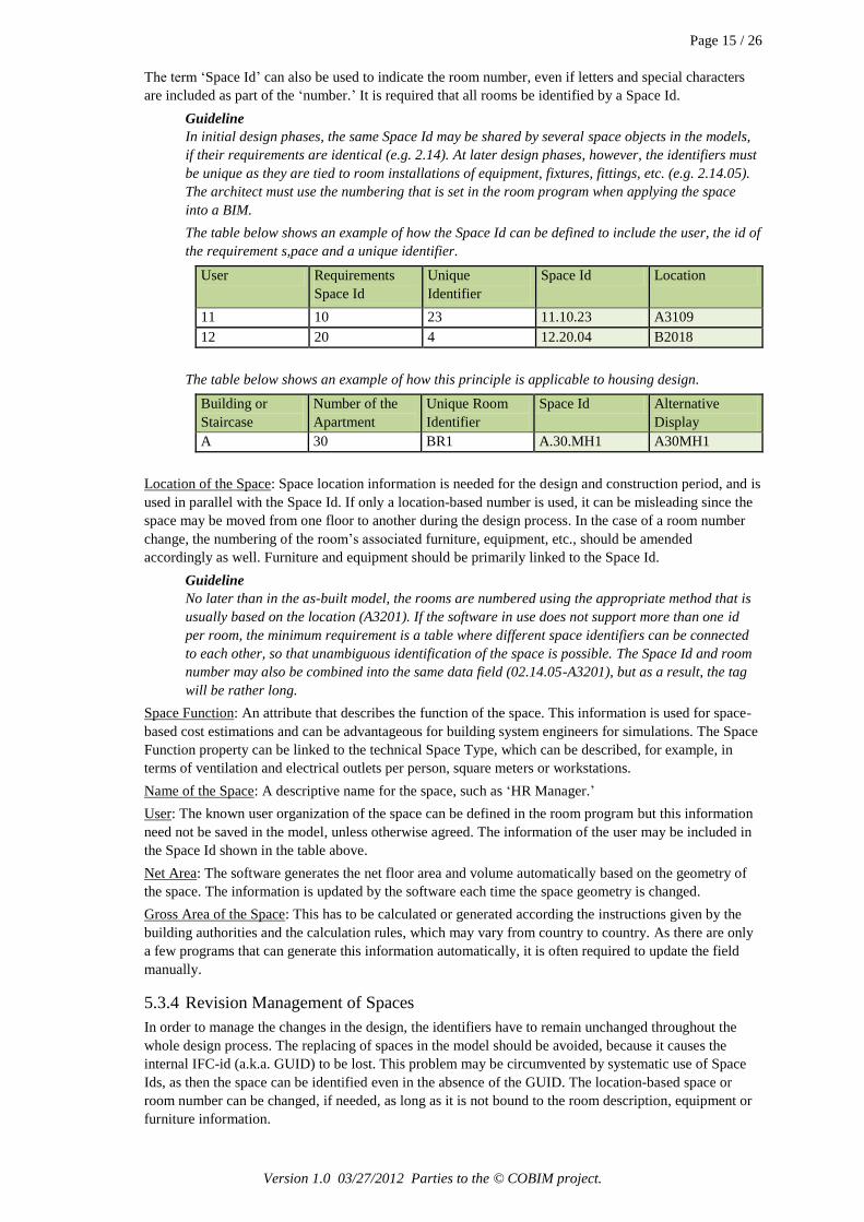
The term ‘Space Id’ can also be used to indicate the room number, even if letters and special characters
are included as part of the ‘number.’ It is required that all rooms be identified by a Space Id.
Guideline
In initial design phases, the same Space Id may be shared by several space objects in the models,
if their requirements are identical (e.g. 2.14). At later design phases, however, the identifiers must
be unique as they are tied to room installations of equipment, fixtures, fittings, etc. (e.g. 2.14.05).
The architect must use the numbering that is set in the room program when applying the space
into a BIM.
The table below shows an example of how the Space Id can be defined to include the user, the id of
the requirement s,pace and a unique identifier.
User Requirements
Space Id
Unique
Identifier
Space Id Location
11 10 23 11.10.23 A3109
12 20 4 12.20.04 B2018
The table below shows an example of how this principle is applicable to housing design.
Building or
Staircase
Number of the
Apartment
Unique Room
Identifier
Space Id Alternative
Display
A 30 BR1 A.30.MH1 A30MH1
Location of the Space: Space location information is needed for the design and construction period, and is
used in parallel with the Space Id. If only a location-based number is used, it can be misleading since the
space may be moved from one floor to another during the design process. In the case of a room number
change, the numbering of the room’s associated furniture, equipment, etc., should be amended
accordingly as well. Furniture and equipment should be primarily linked to the Space Id.
Guideline
No later than in the as-built model, the rooms are numbered using the appropriate method that is
usually based on the location (A3201). If the software in use does not support more than one id
per room, the minimum requirement is a table where different space identifiers can be connected
to each other, so that unambiguous identification of the space is possible. The Space Id and room
number may also be combined into the same data field (02.14.05-A3201), but as a result, the tag
will be rather long.
Space Function: An attribute that describes the function of the space. This information is used for space-
based cost estimations and can be advantageous for building system engineers for simulations. The Space
Function property can be linked to the technical Space Type, which can be described, for example, in
terms of ventilation and electrical outlets per person, square meters or workstations.
Name of the Space: A descriptive name for the space, such as ‘HR Manager.’
User: The known user organization of the space can be defined in the room program but this information
need not be saved in the model, unless otherwise agreed. The information of the user may be included in
the Space Id shown in the table above.
Net Area: The software generates the net floor area and volume automatically based on the geometry of
the space. The information is updated by the software each time the space geometry is changed.
Gross Area of the Space: This has to be calculated or generated according the instructions given by the
building authorities and the calculation rules, which may vary from country to country. As there are only
a few programs that can generate this information automatically, it is often required to update the field
manually.
5.3.4 Revision Management of Spaces
In order to manage the changes in the design, the identifiers have to remain unchanged throughout the
whole design process. The replacing of spaces in the model should be avoided, because it causes the
internal IFC-id (a.k.a. GUID) to be lost. This problem may be circumvented by systematic use of Space
Ids, as then the space can be identified even in the absence of the GUID. The location-based space or
room number can be changed, if needed, as long as it is not bound to the room description, equipment or
furniture information.

Page 16 / 26
Version 1.0 03/27/2012 Parties to the © COBIM project.
5.3.5 Determination of Areas and Volumes
Three dimensional spaces, space groups and volumes are modeled with space or zone tools in such a way
that their geometries can be used to automatically calculate areas and volumes.
Guideline
The area and the volume of the space should take into account all of the building components that
should be included into the room area according to the National Building Code's rules.
The designer is responsible for ensuring that the areas presented in the project's official documents
comply with the National Building Code instructions, even if the modeling software used does not
support this.
If the Spatial or Spatial Group BIM is modeled without partition walls, the default space area either
includes the footprint area of the walls, or the spaces that have been placed within an estimated wall
distance from each other. The chosen approach has to be recorded into the Model Description.
Depending on the software, the following spaces are modeled into the main model or into a separate file:
Net Area
Each individual space has a net area boundary enclosed by the internal surface of walls excluding the
columns, load-bearing walls and the chimney area. It is recommended to use a tool that generates the
space automatically from the bounding objects.
Gross Area
The gross area space is modeled into each building story and it’s height is the height of the story from the
top of the floor finish to the top of the floor finish on the floor above. It’s outer ring is the same as the
outer surface of external walls. This space is used for analysis, calculation of key indicators as well as in
the detection of missing or overlapping spaces. In most cases, this has to be generated manually.
Other Areas
Other areas that need to be included in the model are defined by the client or in the project agreement.
When defining other areas, it must be taken into account that some areas, such as apartments and
departments, can be exactly the same thing and therefore only one of them is required in the project. Floor
areas, fire departments, apartments and other potentially relevant areas are modeled using the appropriate
tools found in the software. Overlaying spaces should be separated either by using layers or by splitting
them into separate files.
Volume (Spaces, Space Groups and Gross Area)
Volume information is defined by the geometry of the space, and should also be transferred to IFC
format. Spaces must comply with the height of the room - measured from the top of the finished floor to
the lower surface of the slab above or, in some cases, to the bottom of the ceiling. The modeling method
used must be documented into the Model Description.
An ‘Assembly of Gross Areas and Volumes’ represents the total volume and gross area of the building.
This information is used, for example, in quantity and cost estimations and in the building permit process
along with other project-based analyses.
5.3.6 Data Exchange
The architect must provide spaces with numbers, functions, areas and volumes in the native format of the
software as well as in IFC format.
Depending on the software used, it may be possible to export the spatial information as a spreadsheet or
database. This date needs to be linked with the room program in order to carry out comparisons of
different design alternatives and phases.

Page 17 / 26
Version 1.0 03/27/2012 Parties to the © COBIM project.
SPATIAL BIM
Initial Data:
Preliminary Room Program (Owner)
Energy Efficiency Goals for the Building (Owner)
Determination of the heat conductivity coefficient of structural elements (Structural
Engineer)
For content and requirements of the model, see section 6
Remarks:
The data exchange between the software that is going to be used has to be examined
If the model is not going to be used for simulations, windows are not obligatory in this phase
The Benefits of the Model:
Preliminary quantities
Room schedules
Overall area and volume information
Grouping of spaces
Initial model for simulations
Visualizations
Site planning and massing models
5.4 General Design
In the general design phase proposals are developed towards the final design. The default BIM Content
Level is 1, but for specific building components this can be upgraded to Level 2 to meet the project needs.
The general design phase aims for the fixed design solution, but in some cases it may still include various
alternative room layouts.
A Building Element BIM consists of the standard components such as walls, tiles, stairs, windows and doors.
European School in Helsinki, Finland; Senate Properties, ISS Suunnittelupalvelut Oy
5.4.1 Building Element BIM
True to its name, the Building Element BIM includes building elements in addition to spaces. A Building
Element BIM is a dimensionally accurate model according to the requirements described in Series 1
‘General Requirements.’
Page 18 / 26
Version 1.0 03/27/2012 Parties to the © COBIM project.
When the Building Element BIM is published in a phase, within which all the type information for
structural parts is not yet defined, the undefined elements are named using a nomenclature such as used in
Talo2000.
Each building story is typically modeled as a separate entity, so that multi-story high walls and spaces are
split by the story height.
5.4.2 Building Element BIM During the General Design Phase
The drawings needed for a building permit application are produced from the Building Element BIM.
Building permit drawings and other documents must meet the level of accuracy and content of the
standards set by building authorities, even if the information is not required in the model.
In the general design phase the Building Element BIM content may be more limited in the following
respects:
The model components can be modeled using the nominal dimensions rather than the actual
installation dimensions. For the final Building Element BIM, however, the actual dimensions, such as
openings for doors and windows, are required. Sometimes it is useful to apply the actual dimensions
of the openings already in this phase, if they are known. The modeling method used will be recorded
in the Model Description.
The surface material information for room surfaces is not required.
The actual type and mounting information for windows and doors is not required, but the functional
information and special requirements must be able to be identified (e.g. fire door).
Modeling of service and access platforms is not required.
Modeling of service hatches is not required.
The preliminary types of building elements should be defined and used in the model. The exterior
walls, load-bearing interior walls and partition walls need to be separated from each other. In order to
identify the building parts and their purposes, it is recommended to use a classification such as
Talo2000 nomenclature.
With the exceptions described above, the requirements for the building component modeling are the same
as in the detail design phase.
5.5 Detail Design Phase
In the detail design phase the design is developed to meet the requirements of the construction phase. The
initial BIM Content Level is 1 or 2 depending on the project, but for certain building parts the accuracy
may be increased to Level 3. In projects where the contractor has not yet been selected at this stage,
achieving a Level 3 model may be impossible, or at least may result in additional work during the
construction phase. Product and system part modeling is included into the BIM in the detail design phase.
5.5.1 Building Element BIM in the Detail Design Phase
The final Building Element BIM is typically finalized in the bidding and detail design phase. All the
building components in the model are specified with the same types as are defined in the Construction
Specifications document. Product information is not required if not otherwise agreed.
5.5.2 Modeling of Building Elements
Walls
Walls are modeled using the wall tool. Walls are modeled from the top of the finished floor to the lower
surface of the slab above, excluding the exterior walls and other multi-story walls which are split by story
but should extend primary from top of the floor finish to the finish elevation of the floor above. In most
cases, the wall structure includes all the sub-components (Level 2). It is also possible to agree that the
walls be split into components which are then modeled separately (Level 3). The Level 3 modeling
method is often associated with special situations, such as acoustically complex structures, construction
types with unique needs, or unusual structural solutions.
The architect should distinguish explicitly the inner walls and outer walls from each other with the type
information, and this type information has to be saved into IFC format as well.
The walls have to be linked to the spaces which they enclose as well as to related walls. Typically the
design software creates these links automatically, if the modeling is done accurately without gaps
between the wall and space components. The quality of the model can be verified using quality assurance
software before the release of the models.
Page 19 / 26
Version 1.0 03/27/2012 Parties to the © COBIM project.
Guideline
In general, multi-story high walls are modeled separately for each building story, however, the
nature of the project and the intended use of the model may require a different approach. Some
software even support automatic slicing of the model by story when the model is exported into the
IFC format. This slicing is not appropriate in all cases as the walls that extend above or below the
story limits may split illogically and story-specific quantities may be inaccurate.
Doors and Windows
Doors and windows are modeled with the corresponding tools in the software. The type of the door or
window has to be included in addition to information regarding mountings and fittings. However, this
information is not required in the preliminary Building Element BIM. Mountings and fittings can be
represented by using a single code in the component within the model. The description of details can be
listed in a separate table, for example, as long as it can be linked to the code in the model element. The
method and coding used is described in Model Description document.
Guideline
In most cases, the door tool can be used to model also other types of openings. In such a situation,
one must take care that the opening is not accidentally interpreted as a normal door. The door will
always be positioned into a wall and it should not extend outside of the wall. The door should be
linked to the wall in which it is located.
In the detail design phase, the windows and doors are modeled so that the installation gaps are included in
the overall dimensions of the door opening (e.g. opening dimensions).
Guideline
If the software allows, it is advisable to make door and window components in such a way that the
dimensions entered are nominal, but so that the actual dimensions in the model include the
opening. The frame dimensions can be included in the model object or as additional information in
the window or door attributes. The methods and attributes used are documented in the Model
Description.
Doors and windows should be linked to a space. In most cases the space will need to be refreshed if a new
a window or door is inserted. Connections to space boundaries (walls and openings) are usually generated
automatically by the software when a space is created or refreshed.
Curtain Walls and other Glazed Facades
If the model has curtain walls or facades, which consist entirely of windows and doors, a solid wall (so
called host wall) should be modeled first, and the windows and doors, which make up the glass wall,
should be added after that. Particular attention should be paid to the fact that there are no gaps between
the host wall and the walls that it is connected to.
When the walls are split by story and the windows spread over several floors, one must ensure that there
are appropriate openings for the windows in each floor and that the windows and openings are linked to
the appropriate spaces.
Guideline
When modeling curtain walls using the software tools, they must be transferred in the correct way
to the IFC format. As curtain walls may cause problems in the IFC data exchange and further use
of the model, their use has to be documented carefully in the Model Description.
Slabs
Foundation, floor and roof slabs are modeled with the appropriate tools in the software. If the modeling
properties of the tool are insufficient (for example, the tool is not able to handle slabs with free 3D form),
the slab can be replaced with a general model object. In that case, the purpose and identity of the slab has
to be presented by name, layer etc. Floor slopes (for example those which direct water flow towards the
floor drain in a bathroom) are not normally modeled.
Guideline
Free-form shapes and different roof lanterns are becoming more common in architecture and set
additional challenges for BIM. Although IFC generally supports the exchange of complex
geometry very well , problems of interpretation can arise when the software is trying to utilize the
IFC-based data. Complex forms may require alternative modeling approaches which should be
agreed on a project-by-project basis. Furthermore, the quantity calculations of these elements
cannot be based on area and volume figures alone, and require a professional interpretation.

Page 20 / 26
Version 1.0 03/27/2012 Parties to the © COBIM project.
The connection of a slab to a wall should be modeled in such a way that they do not overlap and there is
no gap between them. This ensures that the quantities and cost calculations are consistent. The floor slabs
should be aligned to the inner surface of the external walls if not otherwise agreed in the project.
Guideline
Any thermal insulation that is associated with the slab are normally modeled as a part of the slab,
but in special cases they can be modeled as separate building elements using the slab tool.
Significant bulky acoustic insulation materials are presented in the architectural model, unless
otherwise agreed in the project.
Beams and Columns
Beams are modeled with the appropriate beam tool in the software. If the modeling properties of the tool
are insufficient (e.g. tool cannot model the sloping or beveled beams) the beam can be replaced with a
general model object. In that case, the purpose and identity of the beam has to be presented by name,
layer etc.
Columns are modeled with the appropriate column tool in the software. If the modeling properties of the
tool are insufficient (e.g. tool cannot model a column which cross-sectional shape varies) the column can
be replaced with a general model object. In that case, the purpose and identity of the column has to be
presented by name, layer etc.
Guideline
Typically, quantities of beams and columns are not calculated from the Architectural BIM, so
maintaining an absolutely correct modeling method is not imperative. The architect often does not
even have the necessary information of the structural dimensions of beams and columns, or how
they relate to other structures. For example, one solution for this situation is that only the visible
part of the beam is modeled in the architectural model. When the structural model is available, the
dimensions of the beams should be checked in order to avoid design errors.
In the architectural model, the heights of the columns are modeled in a similar manner as spaces
i.e. from the floor finish to the underside of the slab above. Overlapping columns with slabs can
cause unnecessary error messages in quality assurance. If the column is located in a multi-story
high space, the columns are split by story and modeled the same way as external walls. In some
cases it may be more sensible to model the multi-story high columns as one piece. Columns that
are partly inside a wall may overlap the wall, and the walls do not have to split under the column.
Pilasters can be modeled with either the column or the wall tool.
Stairs
Stairs are modeled with the stair tool, separately for each building story. If necessary, landings may be
modeled as slabs.
Guideline
Stairs are still a stumbling block for most modeling software as the accuracy of the model and the
plan view presentation by the rules of drafting are a demanding combination. For quantity
calculation purposes, the interpretation of different parts of the stair requires the use of software
that is used for the design. The calculation, however, can benefit from the final count of the
number of different types of stairs, so it is important that the stairs are given a type or code similar
to walls and other building elements.
Other Building Elements
Double facades (for example, a grille or glazing overlaying the wall) are modeled as separate structures
from the actual wall according to modeling requirements set for walls and curtain walls.
Plinths and foundation walls are modeled with the wall tool and their type or name must ensure that they
stand out from the normal walls. Foundations generally do not need to be modeled in the architectural
model.
Service and access platforms are modeled with the slab tool or with other modeling tools combined with
the required identification (name or classification).
Shafts bigger than 0.5 m2 in area are modeled as spaces surrounded by walls in a similar manner as other
spaces and can be equipped with a service hatch or door.
Ceilings are modeled with the ceiling tool or the slab tool. They must have an identifier (name or code) in
order to be differentiated from other slabs and slab-like building entities. The ceiling structure and the
ceiling tile are in most cases modeled as one piece (Level 2), whose thickness is their combined total
thickness. A suspended ceiling grid (Level 3) or ceiling struts are generally not modeled.
Page 21 / 26
Version 1.0 03/27/2012 Parties to the © COBIM project.
Fixtures and equipment are modeled using the object libraries or appropriate tool in the software. Their
identity must include the type (name or code). Furniture should be logically organized with classifications
or layers so that it is possible to utilize them in bidding or, if needed, in order to exclude them from the
IFC export.
Shelters are modeled using the wall, slab and space tools. Furniture, fittings and equipment are modeled
the same way as elsewhere.
All the building elements of a different type than those listed here should be modeled as separate
components and must be clearly marked for identification by name or classification.
5.5.3 Space in the Building Element BIM
Space included in the Spatial Model should be maintained in the Building Element BIM and modified if
necessary. If a space is removed and replaced, the unique identifier (GUID) for the space is lost.
Therefore, the unnecessary removal and re-modeling of spaces should be avoided, unless it is absolutely
necessary (for example, a complete change in the order or layout of the rooms). Spatial information from
the model is utilized in the room specification.
Guideline
The material information associated with the spaces as well as room schedules and reports must
be linked to the entities in the BIM using the Space Id and the name of room. The underlying
information can be stored either in the property fields of the space itself or in a separate external
table or database. The method, attribute fields, table or database name and form used must be
recorded into the Model Description.
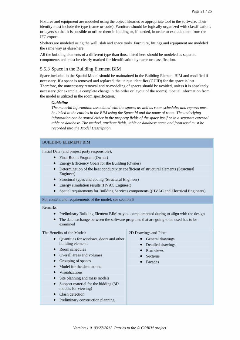
BUILDING ELEMENT BIM
Initial Data (and project party responsible):
Final Room Program (Owner)
Energy Efficiency Goals for the Building (Owner)
Determination of the heat conductivity coefficient of structural elements (Structural
Engineer)
Structural types and coding (Structural Engineer)
Energy simulation results (HVAC Engineer)
Spatial requirements for Building Services components ((HVAC and Electrical Engineers)
For content and requirements of the model, see section 6
Remarks:
Preliminary Building Element BIM may be complemented during to align with the design
The data exchange between the software programs that are going to be used has to be
examined
The Benefits of the Model:
Quantities for windows, doors and other
building elements
Room schedules
Overall areas and volumes
Grouping of spaces
Model for the simulations
Visualizations
Site planning and mass models
Support material for the bidding (3D
models for viewing)
Clash detection
Preliminary construction planning
2D Drawings and Plots:
General drawings
Detailed drawings
Plan views
Sections
Facades

Page 22 / 26
Version 1.0 03/27/2012 Parties to the © COBIM project.
5.6 Construction
Construction control ensures the conformity of the contract execution and that the end result meets the
objectives and the necessary operating and maintenance capabilities.
5.6.1 BIM in Construction
An on-site model is used in the supervision and management of the construction schedule. The level of
accuracy required in the architectural model during the construction phase must be agreed in accordance
with the needs of the construction site.
Guideline
Depending on the project, raising the level of accuracy from Level 2 to Level 3 can mean an
extensive additional workload to create the architectural model. It is essential to agree on the
required level of model accuracy in advance.
Changes in design must be updated into the Building Element BIM that is used on the construction site.
Depending on the contractors, designs may benefit from studies made with the help of BIM instead of
using paper copies.
With the design software or with various model viewers (Solibri, NavisWorks, Tekla BIMsight, etc.) the
BIM can be explored real-time on a screen in 3D walk mode. These programs also allow printing out
hardcopies of the chosen model views.
Utilizing the BIM on the construction site is explained in detail in Series 13 ‘Use of Models in
Construction’.
5.7 Reception
5.7.1 As-Built BIM
When the building is complete, the architect must update the Building Element BIM to correspond with
the final implementation. The goal is for the final BIM to correspond with the end result ‘as-built’ and can
be used as the basis for facility management, building maintenance and modifications made during
occupancy. The required information content is the same as that for the Building Element BIM.
5.8 Implementation and Maintenance
During the warranty period the building performance will be monitored, necessary adjustments and
inspections are made, and corrections to any deficiencies are carried out.
5.8.1 Maintenance BIM
A maintenance model can help with facility and property management during the life cycle of the
building. The results of Indoor Climate Simulations carried out in the design phase can be compared to
actual conditions. The Building Element BIM can be modified to make a separate model for maintenance
purposes which contains only the essential objects and information, since the requirements for
maintenance BIM may differ from those of the Design and Construction BIM.
MAINTENANCE BIM
Initial Data:
As-Built BIM and design documentation
Completed building
For content and requirements of the model, see section 6
Remarks
The BIM that was used for design and construction purposes might be too complex for the
maintenance
Simulations and facility management may require a simplified model
The final room numbering must be added at the latest during the implementation phase

Page 23 / 26
Version 1.0 03/27/2012 Parties to the © COBIM project.
The Benefits of the Model:
Quantities for equipment, windows, doors and other building elements
Room schedules, rentable areas
Overall areas and volumes
Grouping of spaces
Model for the simulations
Visualizations, signs, location maps

Page 24 / 26
Version 1.0 03/27/2012 Parties to the © COBIM project.
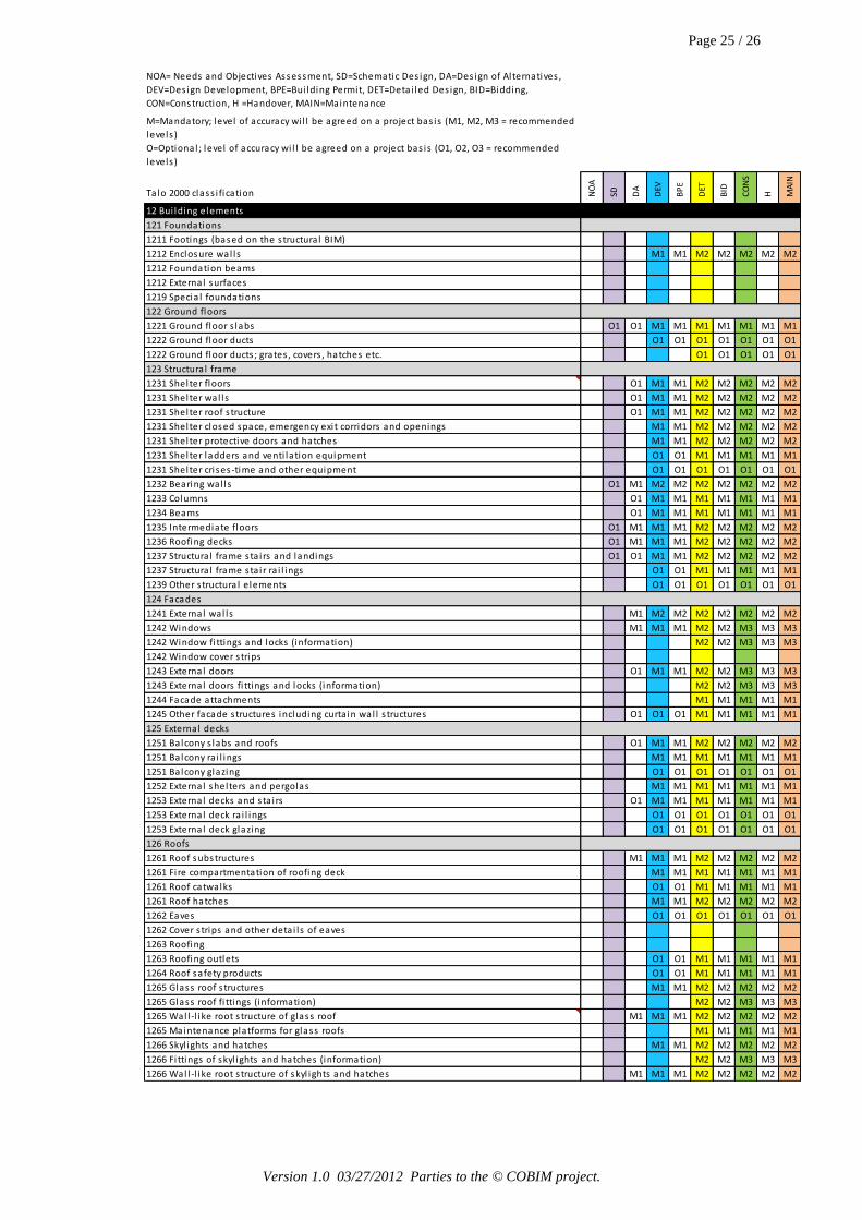
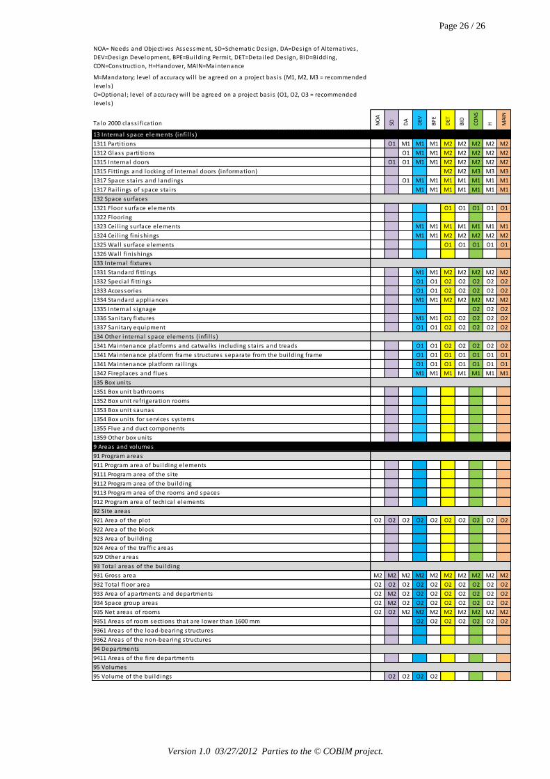
6 BIM Requirements in Various Project Phases The following table presents a list of content requirements for the Architectural BIM at various stages of
the project. Mandatory tasks are marked with the letter P followed by the recommended BIM Content
Level, which is marked using numbers 1, 2 or 3. Optional tasks to be defined on a project-by-project basis
are marked with the letter V followed by the recommended BIM Content Level. Other BIM-based
functions may be specified by the project team or the facility owner.
A more detailed description of the Model Content Levels for an Architectural BIM are defined in section
3.3 ‘BIM Content Levels’.
NOA= Needs and Objectives Assessment, SD=Schematic Des ign, DA=Des ign of Al ternatives ,
DEV=Des ign Development, BPE=Bui lding Permit, DET=Detai led Des ign, BID=Bidding,
CON=Construction, H=Handover, MAIN=Maintenance
M=Mandatory; level of accuracy wi l l be agreed on a project bas is (M1, M2, M3 = recommended
levels )
O=Optional ; level of accuracy wi l l be agreed on a project bas is (O1, O2, O3 = recommended
levels )
Ta lo 2000 class i fication NO
A
SD DA
DEV
BP
E
DET
BID
CO
NS
H MA
IN
11 Si te elements (Si te BIM)
111 Ground elements
1111 Clearing elements O1 O1 O1 O1 O1
1114 Fi l l ing on s i te
1115 Embankments
1119 Other ground elements
113 Paved and green areas
1131 Traffic area pavings
1132 Parking area pavings
1133 Leisure and play area pavings
1134 Green areas
1139 Other area pavings
114 Si te equipment
1141 Bui lding equipment O2 O2 O2 O2 O2
1142 Leisure equipment O2 O2 O2 O2 O2
1143 Play equipment O2 O2 O2 O2 O2
1144 Si te s ignage
1149 Other s i te equipment
115 Si te construction
1151 Yard sheds O1 M1 M1 M2 M2 M2 M2 M2
1152 Yard shelters and pergolas O1 O1 O1 O1 O1 O1 O1
1153 Fences and reta ining wal ls O1 O1 O1 O1 O1 O1 O1
1154 Si te s ta i rs , ramps and terraces O1 O1 O1 O1 O1 O1 O1
1155 Si te parking faci l i ties O2 O2 O2
1159 Other s i te constructions
Page 25 / 26
Version 1.0 03/27/2012 Parties to the © COBIM project.
NOA= Needs and Objectives Assessment, SD=Schematic Des ign, DA=Des ign of Al ternatives ,
DEV=Des ign Development, BPE=Bui lding Permit, DET=Detai led Des ign, BID=Bidding,
CON=Construction, H =Handover, MAIN=Maintenance
M=Mandatory; level of accuracy wi l l be agreed on a project bas is (M1, M2, M3 = recommended
levels )
O=Optional ; level of accuracy wi l l be agreed on a project bas is (O1, O2, O3 = recommended
levels )
Ta lo 2000 class i fication NO
A
SD DA
DEV
BP
E
DET
BID
CO
NS
H MA
IN
12 Bui lding elements
121 Foundations
1211 Footings (based on the s tructura l BIM)
1212 Enclosure wal ls M1 M1 M2 M2 M2 M2 M2
1212 Foundation beams
1212 External surfaces
1219 Specia l foundations
122 Ground floors
1221 Ground floor s labs O1 O1 M1 M1 M1 M1 M1 M1 M1
1222 Ground floor ducts O1 O1 O1 O1 O1 O1 O1
1222 Ground floor ducts ; grates , covers , hatches etc. O1 O1 O1 O1 O1
123 Structura l frame
1231 Shelter floors O1 M1 M1 M2 M2 M2 M2 M2
1231 Shelter wal ls O1 M1 M1 M2 M2 M2 M2 M2
1231 Shelter roof s tructure O1 M1 M1 M2 M2 M2 M2 M2
1231 Shelter closed space, emergency exi t corridors and openings M1 M1 M2 M2 M2 M2 M2
1231 Shelter protective doors and hatches M1 M1 M2 M2 M2 M2 M2
1231 Shelter ladders and venti lation equipment O1 O1 M1 M1 M1 M1 M1
1231 Shelter crises -time and other equipment O1 O1 O1 O1 O1 O1 O1
1232 Bearing wal ls O1 M1 M2 M2 M2 M2 M2 M2 M2
1233 Columns O1 M1 M1 M1 M1 M1 M1 M1
1234 Beams O1 M1 M1 M1 M1 M1 M1 M1
1235 Intermediate floors O1 M1 M1 M1 M2 M2 M2 M2 M2
1236 Roofing decks O1 M1 M1 M1 M2 M2 M2 M2 M2
1237 Structura l frame sta i rs and landings O1 O1 M1 M1 M2 M2 M2 M2 M2
1237 Structura l frame sta i r ra i l ings O1 O1 M1 M1 M1 M1 M1
1239 Other s tructura l elements O1 O1 O1 O1 O1 O1 O1
124 Facades
1241 External wal ls M1 M2 M2 M2 M2 M2 M2 M2
1242 Windows M1 M1 M1 M2 M2 M3 M3 M3
1242 Window fi ttings and locks (information) M2 M2 M3 M3 M3
1242 Window cover s trips
1243 External doors O1 M1 M1 M2 M2 M3 M3 M3
1243 External doors fi ttings and locks (information) M2 M2 M3 M3 M3
1244 Facade attachments M1 M1 M1 M1 M1
1245 Other facade s tructures including curta in wal l s tructures O1 O1 O1 M1 M1 M1 M1 M1
125 External decks
1251 Balcony s labs and roofs O1 M1 M1 M2 M2 M2 M2 M2
1251 Balcony ra i l ings M1 M1 M1 M1 M1 M1 M1
1251 Balcony glazing O1 O1 O1 O1 O1 O1 O1
1252 External shelters and pergolas M1 M1 M1 M1 M1 M1 M1
1253 External decks and s ta i rs O1 M1 M1 M1 M1 M1 M1 M1
1253 External deck ra i l ings O1 O1 O1 O1 O1 O1 O1
1253 External deck glazing O1 O1 O1 O1 O1 O1 O1
126 Roofs
1261 Roof substructures M1 M1 M1 M2 M2 M2 M2 M2
1261 Fi re compartmentation of roofing deck M1 M1 M1 M1 M1 M1 M1
1261 Roof catwalks O1 O1 M1 M1 M1 M1 M1
1261 Roof hatches M1 M1 M2 M2 M2 M2 M2
1262 Eaves O1 O1 O1 O1 O1 O1 O1
1262 Cover s trips and other deta i l s of eaves
1263 Roofing
1263 Roofing outlets O1 O1 M1 M1 M1 M1 M1
1264 Roof safety products O1 O1 M1 M1 M1 M1 M1
1265 Glass roof s tructures M1 M1 M2 M2 M2 M2 M2
1265 Glass roof fi ttings (information) M2 M2 M3 M3 M3
1265 Wal l -l ike root s tructure of glass roof M1 M1 M1 M2 M2 M2 M2 M2
1265 Maintenance platforms for glass roofs M1 M1 M1 M1 M1
1266 Skyl ights and hatches M1 M1 M2 M2 M2 M2 M2
1266 Fi ttings of skyl ights and hatches (information) M2 M2 M3 M3 M3
1266 Wal l -l ike root s tructure of skyl ights and hatches M1 M1 M1 M2 M2 M2 M2 M2
Page 26 / 26
Version 1.0 03/27/2012 Parties to the © COBIM project.
NOA= Needs and Objectives Assessment, SD=Schematic Des ign, DA=Des ign of Al ternatives ,
DEV=Des ign Development, BPE=Bui lding Permit, DET=Detai led Des ign, BID=Bidding,
CON=Construction, H=Handover, MAIN=Maintenance
M=Mandatory; level of accuracy wi l l be agreed on a project bas is (M1, M2, M3 = recommended
levels )
O=Optional ; level of accuracy wi l l be agreed on a project bas is (O1, O2, O3 = recommended
levels )
Ta lo 2000 class i fication NO
A
SD DA
DEV
BP
E
DET
BID
CO
NS
H MA
IN
13 Internal space elements (infi l l s )
1311 Parti tions O1 M1 M1 M1 M2 M2 M2 M2 M2
1312 Glass parti tions O1 M1 M1 M2 M2 M2 M2 M2
1315 Internal doors O1 O1 M1 M1 M2 M2 M2 M2 M2
1315 Fi ttings and locking of internal doors (information) M2 M2 M3 M3 M3
1317 Space s ta i rs and landings O1 M1 M1 M1 M1 M1 M1 M1
1317 Rai l ings of space s ta i rs M1 M1 M1 M1 M1 M1 M1
132 Space surfaces
1321 Floor surface elements O1 O1 O1 O1 O1
1322 Flooring
1323 Cei l ing surface elements M1 M1 M1 M1 M1 M1 M1
1324 Cei l ing finishings M1 M1 M2 M2 M2 M2 M2
1325 Wal l surface elements O1 O1 O1 O1 O1
1326 Wal l finishings
133 Internal fixtures
1331 Standard fi ttings M1 M1 M2 M2 M2 M2 M2
1332 Specia l fi ttings O1 O1 O2 O2 O2 O2 O2
1333 Accessories O1 O1 O2 O2 O2 O2 O2
1334 Standard appl iances M1 M1 M2 M2 M2 M2 M2
1335 Internal s ignage O2 O2 O2
1336 Sanitary fixtures M1 M1 O2 O2 O2 O2 O2
1337 Sanitary equipment O1 O1 O2 O2 O2 O2 O2
134 Other internal space elements (infi l l s )
1341 Maintenance platforms and catwalks including s ta i rs and treads O1 O1 O2 O2 O2 O2 O2
1341 Maintenance platform frame structures separate from the bui lding frame O1 O1 O1 O1 O1 O1 O1
1341 Maintenance platform ra i l ings O1 O1 O1 O1 O1 O1 O1
1342 Fi replaces and flues M1 M1 M1 M1 M1 M1 M1
135 Box units
1351 Box unit bathrooms
1352 Box unit refrigeration rooms
1353 Box unit saunas
1354 Box units for services systems
1355 Flue and duct components
1359 Other box units
9 Areas and volumes
91 Program areas
911 Program area of bui lding elements
9111 Program area of the s i te
9112 Program area of the bui lding
9113 Program area of the rooms and spaces
912 Program area of techica l elements
92 Si te areas
921 Area of the plot O2 O2 O2 O2 O2 O2 O2 O2 O2 O2
922 Area of the block
923 Area of bui lding
924 Area of the traffic areas
929 Other areas
93 Tota l areas of the bui lding
931 Gross area M2 M2 M2 M2 M2 M2 M2 M2 M2 M2
932 Tota l floor area O2 O2 O2 O2 O2 O2 O2 O2 O2 O2
933 Area of apartments and departments O2 M2 O2 O2 O2 O2 O2 O2 O2 O2
934 Space group areas O2 M2 O2 O2 O2 O2 O2 O2 O2 O2
935 Net areas of rooms O2 O2 M2 M2 M2 M2 M2 M2 M2 M2
9351 Areas of room sections that are lower than 1600 mm O2 O2 O2 O2 O2 O2 O2
9361 Areas of the load-bearing s tructures
9362 Areas of the non-bearing s tructures
94 Departments
9411 Areas of the fi re departments
95 Volumes
95 Volume of the bui ldings O2 O2 O2 O2

Location:
Time:
Auditor:
Target Model:
Version:
Date of Model Version:
Checklist for Architectural Building Element BIM Passed
issues
Not
Rele
vant
Comments
BIM Specification
Models are in Agreed File Formats (IFC and other agreed files)
Agreed Layers has Been Used
Coordinate System is According to Agreement
Model has Floors
Building Elements and Spaces Belong to Correct Floor
Agreed/Required Spaces and Building Elements are Modeled
Building Elements are Modeled Using Correct Tools
Agreed Construction Types are Used
Model Doesn't Have Extra Building Elements
Model Doesn't Have Building Elements Inside Each Other or Duplicate Building Elements
Model Doesn't Have Significant Intersections Between Building Elements
Model has Gross area Spaces (and other required areas)
Spaces Representing areas Have Agreed Names and Types
Agreed Space Identifiers Have Been Used
Spaces Correspond to Space Schedule
Spaces, Walls and Columns Fill Gross area
Spatial Reservations for MEP Systems Have Been Done
Space Heights are According to Agreed Modeling Convention
Spaces Aligned with Walls and Other Components
Spaces Don't Intersect With Each Others
Signature: