coaxial antenna - benelec - innovative radio technology€¦ · · 2009-05-11Ł coaxial antenna...
TRANSCRIPT

ROK/24.8.01 1
Properties and use
Reijo Kekäläinen
Coaxial Antenna

ROK/24.8.01 2
Need for Indoor Coverage Wireless communications are increasing
rapidly Growth in the use of mobile services and
products Growing use of mobile communication
increases the demand for sufficient radio coverage in many places
UMTS frequencies make signal propagation worse because of bigger open air attenuation and even worse building structure penetration
ROK/24.8.01 3
Need for Indoor Coverage
Propagation of electromagnetic waves are disabled into constructions of heavy and conducting material
Portable receiver moving in the building experiences fading
In the future mobility of work makes demands for wireless office
Growing need for security systems for buildings
ROK/24.8.01 4
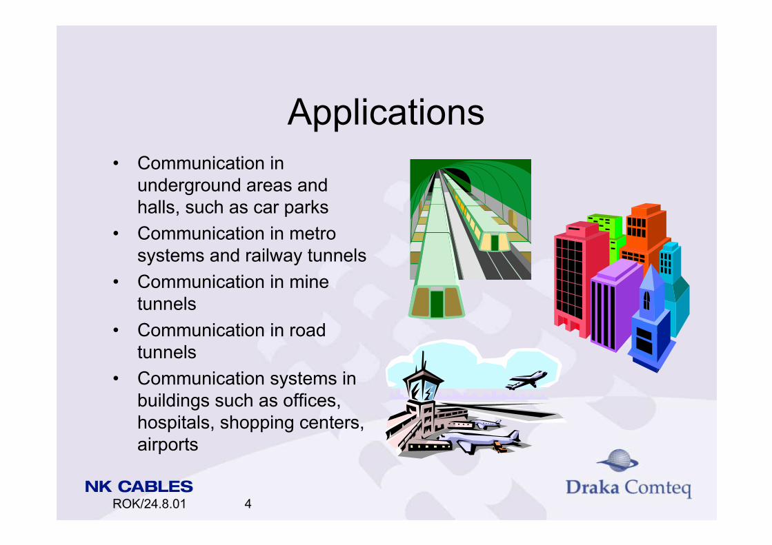
Applications Communication in
underground areas and halls, such as car parks
Communication in metro systems and railway tunnels
Communication in mine tunnels
Communication in road tunnels
Communication systems in buildings such as offices, hospitals, shopping centers, airports

ROK/24.8.01 5
Applications
Police, fire and rescue services in all areas mentioned
Wireless LAN (WLAN) Area access detection and
security AM or FM-radio detection in
radio shadowed places Cordless telephone systems Communication in ships
ROK/24.8.01 6
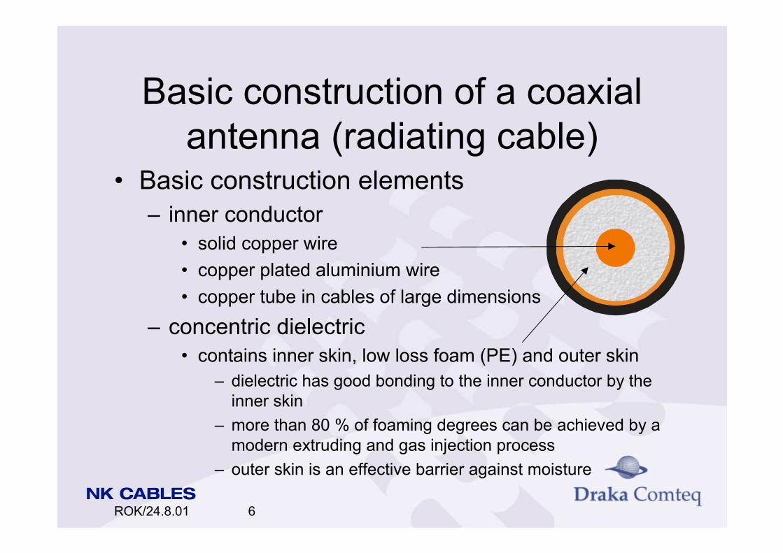
Basic construction of a coaxial antenna (radiating cable)
Basic construction elements inner conductor
solid copper wire copper plated aluminium wire copper tube in cables of large dimensions
concentric dielectric contains inner skin, low loss foam (PE) and outer skin
dielectric has good bonding to the inner conductor by the inner skin
more than 80 % of foaming degrees can be achieved by a modern extruding and gas injection process
outer skin is an effective barrier against moisture

ROK/24.8.01 7
Basic construction of a coaxial antenna
outer conductor welded, corrugated and slotted copper tube or
longitudinal overlapped copper tape with periodic slots determines the radiating properties
mica barrier tape option improves the fire safety of the cable
sheath black HD polyethylene grey or black halogen free fire retardant thermoplastic also other colors available

ROK/24.8.01 8
Coaxial antenna theory
coaxial antenna has basic coaxial cable transmission characteristics with some exceptions:
the TEM wave that propagates inside the cable also radiates outwards from the cable
the coupling mechanism between the cable interior and the external environment can be created by small apertures in the cable outer conductor

ROK/24.8.01 9
Coaxial antenna theory The cable acts as continuous antenna and transmission line
at the same time the electromagnetic coupling mechanism and radiation
characteristics are determined by the configuration of the apertures:
key factors are the size, shape, position and spacing of the apertures
based on the coupling and radiation mechanism cables can be divided for coupled mode cables and radiating mode cables
ROK/24.8.01 10
Coaxial antenna theory
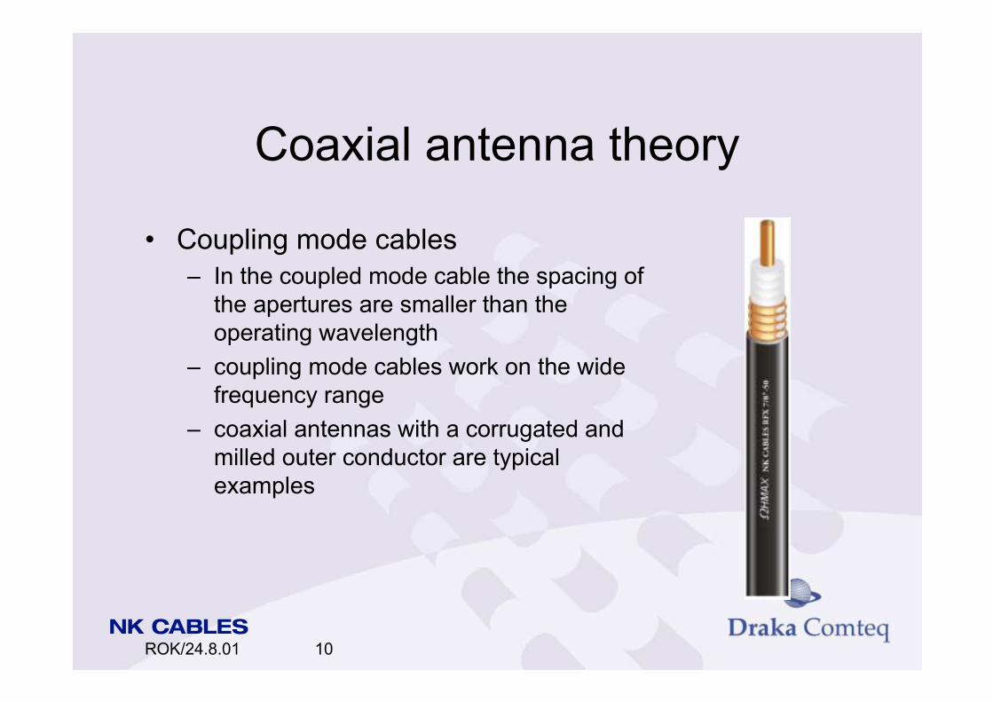
Coupling mode cables In the coupled mode cable the spacing of
the apertures are smaller than the operating wavelength
coupling mode cables work on the wide frequency range
coaxial antennas with a corrugated and milled outer conductor are typical examples

ROK/24.8.01 11
Coaxial antenna theory
Radiating mode cables In the radiating mode cables the apertures
are typically periodically configured with a spacing comparable to the operational frequency
with a proper configuration the cable radiates within the required frequency
coaxial antennas with a slotted overlapped copper tape as outer conductor are typical examples
ROK/24.8.01 12
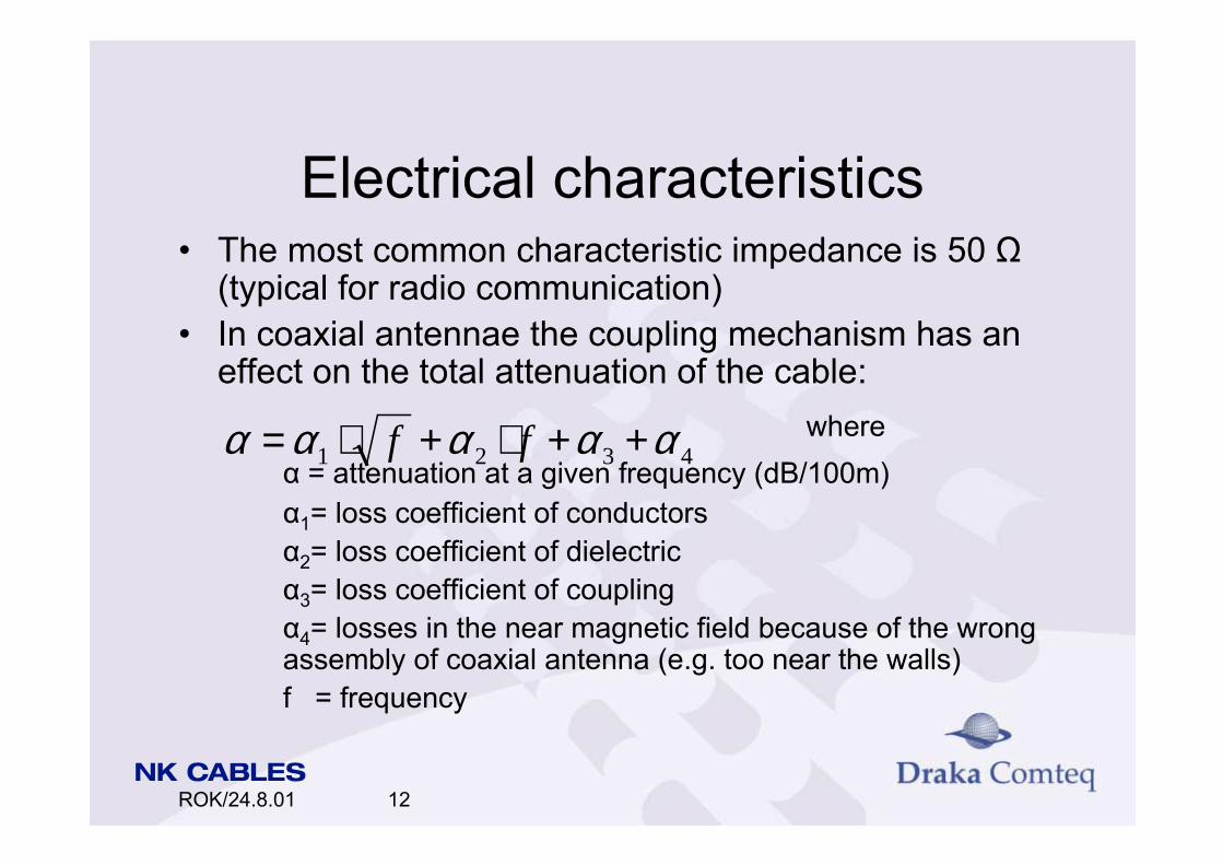
Electrical characteristics The most common characteristic impedance is 50 Ω
(typical for radio communication) In coaxial antennae the coupling mechanism has an
effect on the total attenuation of the cable:where
α = attenuation at a given frequency (dB/100m)α1= loss coefficient of conductorsα2= loss coefficient of dielectricα3= loss coefficient of couplingα4= losses in the near magnetic field because of the wrong assembly of coaxial antenna (e.g. too near the walls)f = frequency
4321 ααααα ++⋅+⋅= ff

ROK/24.8.01 13
Electrical characteristics The attenuation of the coaxial antenna is measured
according to the standard IEC 61196-4 ground level method
cable is laid on non-metallic spacers 10-12 cm from concrete floor
free space method (more common method) cable is laid on wooden posts at height of 1.5-2 m when using this method the attenuation is calculated
using the following formula:
( )[ ] ( )CatmdBTL
NN se o20100/20002.01100 −⋅−⋅⋅−=α

ROK/24.8.01 14
Electrical characteristicswhere α = attenuation (dB/100m at 20ºC)
Ne= power level at the beginning of the cable (dBm)Ns= power level at the end of the cable (dBm)L = length of the cable (m)T = temperature of the cable (ºC)
Coupling loss is measured according the same standard as above
Coupling loss is the ratio of the received power at the antenna
(2 m from cable) to the power in the cable depends on the coupling and radiating mechanism
of the cable

ROK/24.8.01 15
Electrical characteristics is calculated (when using free space method) by
using formulawhere αc= coupling loss (dB)
Ne= power level at the beginning of the cable (dBm)Nr= power level at antenna (dBm)P= distance from antenna to the feeding point (m)
is characterized by two typical values: mean value αc50: 50 % of the measured local values are
smaller than this value mean value αc95: 95 % of the measured local values are
smaller than this value is typically 55-85 dB
( ) )(dBPNN rec ⋅−−= αα

ROK/24.8.01 16
Cable types and main features NK Cables offers several
cable types according to the cable diameter and coupling/radiating mechanism: RFX or RF2X 1/2-50 RFX or RF2X 7/8-50 RFX or RF2X 1 1/4-50 RFX or RF2X 1 5/8-50 RFXT 5/8-50 RFXT 7/8-50 RFXK (several dimensions)

ROK/24.8.01 17
Cable types and main features RFX has a welded corrugated outer conductor
(coupling mode cable) Also RFX with extra fire protection (Mica tape) is
available
RFXT has an overlapped copper tape outer conductor (radiating mode cable)

ROK/24.8.01 18
Cable types and main features Coaxial antennae have the
following main features: low attenuation and optimized
coupling loss high mechanical strength and
stability polyethylene skin over dielectric
as a moisture barrier fire retardant, low smoke and
halogen free sheath available easy installation characteristics colored cables if required
ROK/24.8.01 19
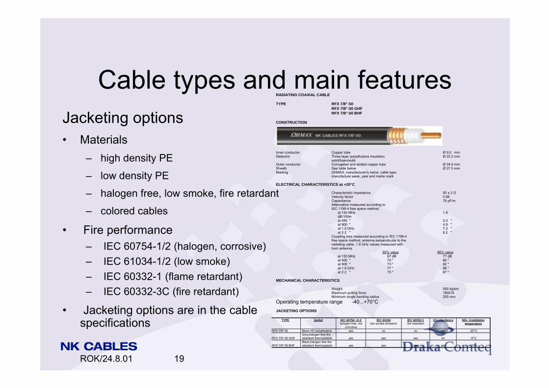
Cable types and main featuresJacketing options Materials
high density PE low density PE halogen free, low smoke, fire retardant colored cables
Fire performance IEC 60754-1/2 (halogen, corrosive) IEC 61034-1/2 (low smoke) IEC 60332-1 (flame retardant) IEC 60332-3C (fire retardant)
Jacketing options are in the cable specifications
RADIATING COAXIAL CABLE TYPE RFX 7/8"-50
RFX 7/8"-50 GHF RFX 7/8"-50 BHF
CONSTRUCTION
Inner conductor Copper tube Ø 9.0 mm Dielectric Three layer polyethylene insulation Ø 22.2 mm
solid/foam/solid Outer conductor Corrugated and slotted copper tube Ø 24.9 mm Sheath See table below Ø 27.5 mm Marking ΩHMAX, manufacturer's name, cable type,
manufacture week, year and metre mark ELECTRICAL CHARACTERISTICS at +20°C
Characteristic impedance 50 ± 2 Ω Velocity factor 0.88 Capacitance 76 pF/m Attenuation measured according to IEC 1196-4 free space method.
at 150 MHz 1.9 dB/100m at 450 " 3.3 " at 900 " 4.9 " at 1.8 GHz 7.3 " at 2.2 " 8.2 "
Coupling loss measured according to IEC 1196-4 free space method, antenna perpendicular to the radiating cable. 1.8 GHz values measured with horn antenna.
50% value 95% value at 150 MHz 67 dB 77 dB at 450 " 70 " 80 " at 900 " 73 " 82 " at 1.8 GHz 77 " 88 " at 2.2 " 75 " 87 "
MECHANICAL CHARACTERISTICS
Weight 550 kg/km Maximum pulling force 1800 N Minimum single bending radius 250 mm
Operating temperature range -40...+70°C JACKETING OPTIONS
TYPE Jacket IEC 60754 -1/-2 halogen free, not
corrosive
IEC 61034 low smoke emission
IEC 60332-1 fire retardant
UV retardancy Min. installation temperature
RFX 7/8"-50 Black HD polyethylene yes no no yes -20°C RFX 7/8"-50 GHF
Grey,halogen free fire retardant thermoplastic
yes
yes
yes
no
-5°C
RFX 7/8"-50 BHF
Black,halogen free fire retardant thermoplastic
yes
yes
yes
yes
-5°C

ROK/24.8.01 20
Indoor system design Here an interior-building project is dealt with Same principles also applied to other applications Information to be required for the initial values
building construction utilization of building equipment location; transmission possibilities etc. floor area; shape number of floors; height, underground parts materials; floors, walls, construction, windows, etc.
(typical loss factors for each material) typical size of rooms; offices, halls, etc. risers; elevators, cable ducts etc.; location

ROK/24.8.01 21
Indoor system design
existing radio environment outdoor BTS near the building
capacity; cells, number of TRXs signal strength; cells, distances, direction used frequencies
indoor system; signal strengths, levels of interference radio environment needs
indoor micro BTS (pico-cell) or utilization of outdoor sites capacity; different needs in different parts of the building coverage; different needs in different parts of the building

ROK/24.8.01 22
Indoor system design limitations
frequency planning; nearby cells, disturbances signal power: EMC requirements, devices and biological
harmful radiation (not possible with coaxial antenna) equipment location costs operator needs

ROK/24.8.01 23
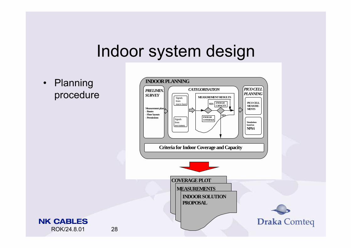
Indoor system design Indoor planning
preliminary survey measurement plan including routes, floor layouts,
permission carry out measurements
analysis (categorization) measuring the signals from macro layer (from BTSs
outside building) measurement results are analyzed to see if there is
enough coverage and capacity inside the building ⇒ if not ⇒ indoor solution is required ⇒ measurements of the signals from test transmission is carried out

ROK/24.8.01 24
Indoor system design pico-cell planning
simulations of the new indoor system (antennae locations)
there are many tools to do the radio network simulations e.g. NPS/i (Nokia tool), SitePlanner, WISE,
in simple systems the calculations can be made by hand (a power budget calculation)
the indoor system proposal is introduced to the operator
coverage plot measurement results indoor solution proposal

ROK/24.8.01 25
Indoor system design Indoor solution
in NK Cables head office inEspoo Finland
implemented in co-operation with Sonera
more uniform coverage achieved compared to the old system (distributed antennae)

ROK/24.8.01 26
Indoor system designINDOOR COVERAGE OF NK CABLES' HEAD OFFICE
0
5
10
15
20
25
30
35
40
45
50
1 3 5 7 9 11 13 15 17 19MEASUREMENT LOCATION NUMBER
MEAS
URED
MAR
GIN
OF S
IGNA
L LE
VEL
(dB)
,CO
MPAR
ISON
LEV
EL -8
0 dBm
1800 network
old distributed antennae network
new coaxial antenna network

ROK/24.8.01 27
Indoor system designCost comparison of networks of NK Cables Head Office
Old distributed antennae network Cables
feeder 8700 connectors 2350 power splitters 8000 antennae 14700 labor costs 42000
Total costs 75750 FIM = 12740 EUR
New coaxial antenna network Cables
feeder 2020 antenna 10020
connectors 2100 power splitters 5600 cable hangers 4530 jumpers 510 terminators 3220 labor costs 44500
Total costs 72500 FIM = 12190 EUR
ROK/24.8.01 28
Indoor system design
PRELIMIN.SURVEY
Measurement plan:- Routes- Floor layouts- Permissions
PICO CELLPLANNING
PICO CELLMEASURE-MENTS
Simulationsbased on
NPS/i
YES
YESENOUGHCOVERAGE
ENOUGHCAPACITY
MEASUREMENT RESULTS
CATEGORISATION
Signalsfrommacro layer
Signals fromtest transm.
INDOOR PLANNING
Criteria for Indoor Coverage and Capacity
INDOOR SOLUTIONPROPOSAL
MEASUREMENTSCOVERAGE PLOT
Planning procedure

ROK/24.8.01 29
Power budget calculation It is the main part of the pico-cell planning Factors for power budget calculation:
base station transmitter output level and receiver sensitivity
jumper cable loss feeder cable loss power divider loss coaxial antenna longitudinal loss repeater gain (gain of the bi-directional amplifier) if
amplifiers needed in system

ROK/24.8.01 30
Power budget calculation filter losses if filters needed in system coupling loss from coaxial antenna cable safety margin (5-20 dB depending on the
installation and the environment) contains fading margin and possible extra margin
mobile station antenna loss or gain mobile station receiver sensitivity and transmitter
output level with simple addition of these factors the probable
signal strength in the radio network can be calculated

ROK/24.8.01 31
Power budget calculationexample at 900 MHz
Output power of Mobile Station (1 W) and antenna gain (0 dBi) 30 dBm
Coupling loss e.g. 82 dB/2 m (here 6 m and 95%) 87 dB
Coupling loss variation (fading) 10 dB
Coaxial antenna attenuation e.g. 49 dB/km (100m) 5 dB
Power divider loss e.g. 3.5 dB (2 pieces) 7 dB
Jumper cable (1 piece) 1 dB
Feeder loss e.g. 39 dB/km (50m) 2 dB
Total 30 dBm 112 dB
Output power minus losses -82 dBm
Receiver sensitivity of base station -112 dBm
Safety margin 20 dB
ROK/24.8.01 32
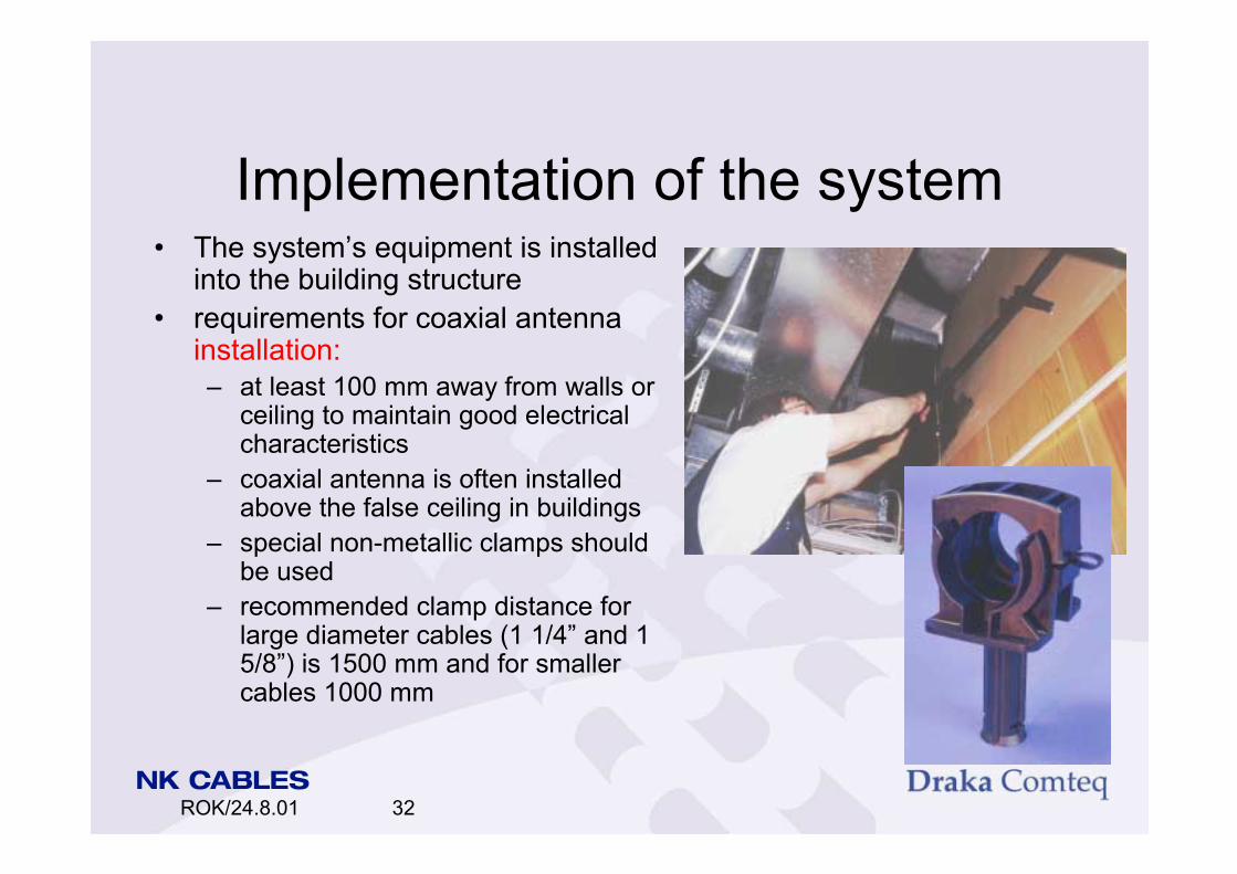
Implementation of the system The systems equipment is installed
into the building structure requirements for coaxial antenna
installation: at least 100 mm away from walls or
ceiling to maintain good electrical characteristics
coaxial antenna is often installed above the false ceiling in buildings
special non-metallic clamps should be used
recommended clamp distance for large diameter cables (1 1/4 and 1 5/8) is 1500 mm and for smaller cables 1000 mm
ROK/24.8.01 33
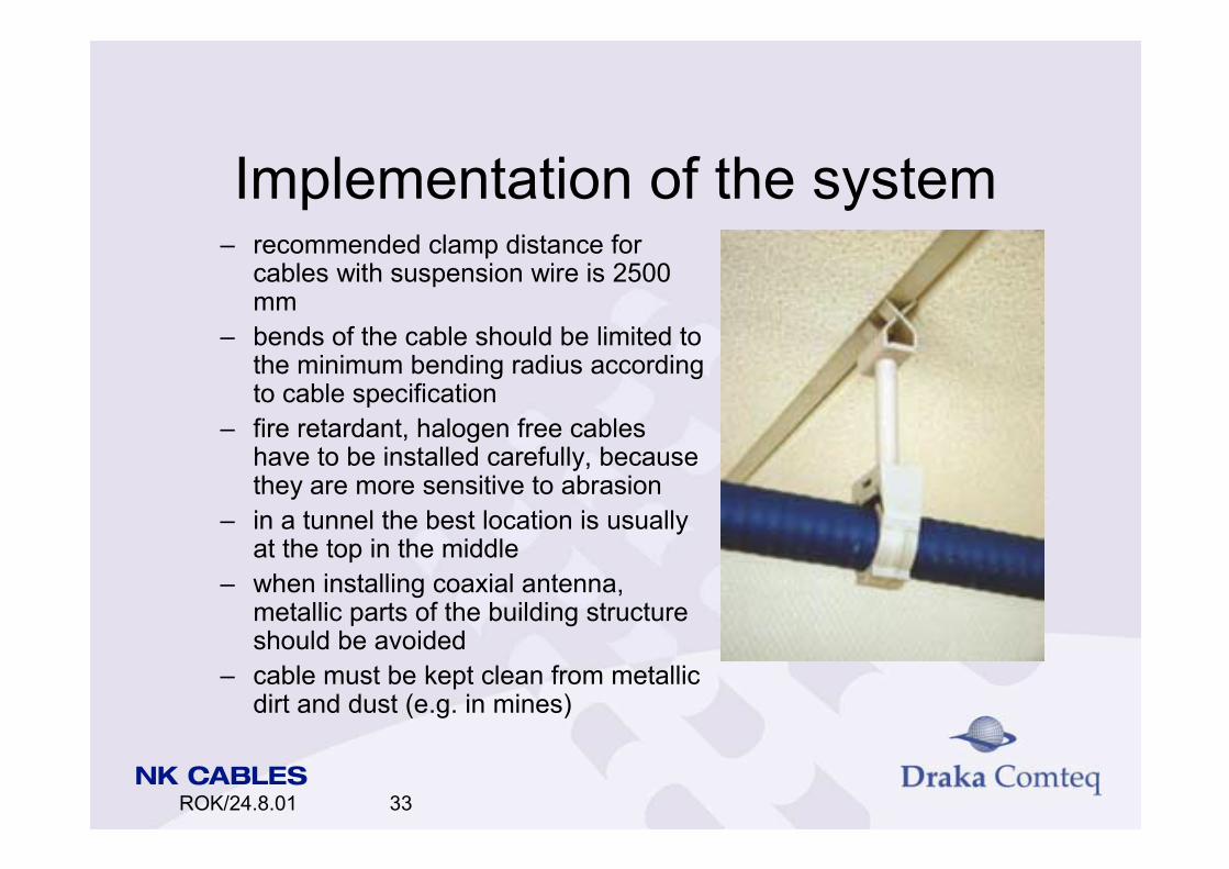
Implementation of the system recommended clamp distance for
cables with suspension wire is 2500 mm
bends of the cable should be limited to the minimum bending radius according to cable specification
fire retardant, halogen free cables have to be installed carefully, because they are more sensitive to abrasion
in a tunnel the best location is usually at the top in the middle
when installing coaxial antenna, metallic parts of the building structure should be avoided
cable must be kept clean from metallic dirt and dust (e.g. in mines)

ROK/24.8.01 34
Implementation of the system Other equipment needed
connectors RFX (corrugated) cables can use
same connectors as normal feeder cables
for RFXT cables special connectors are needed
power splitters and directional couplers
depends on the structure of the project (e.g. 2:1, 10:1, etc.)
50 ohm termination with adequate power handling capability is usually put onto end of antenna line
amplifiers, filters, antennae if needed

ROK/24.8.01 35
System verification Field measurements
stand-alone mobiles radio network measurement software e.g NMS/X
Measurement results are studied and compared to the designed parameters
Parameter tuning based on network statistics and field
measurement data to gain best possible quality and performance out
of existing installation The effect of the new setting is monitored again

ROK/24.8.01 36
System verification
Verification finally the building is verified by using available
radio network software a predefined verification procedure is usually used the verification report to the operator is checked
against the planning criteria final acceptance is achieved

ROK/24.8.01 37
System verification
Optimisationand verification tasks
Verification Raport
Measurements
ParamterTuningField
Measurements
NMS Statistics
OPTIMISATION
FieldMeasurements
NMS Statistics
VERIFICATION
PLANNING AFTER IMPLEMENTATION

ROK/24.8.01 38
Benefits of using coaxial antenna in indoor systems
Easy to use and design Usually an inexpensive solution compared to the
other structures gives uniform response along the antenna line fewer blocking characteristics doesnt disturb other systems in the building gives off no harmful radiation to people nearby plugs in the tunnel structures dont affect the
response

ROK/24.8.01 39
Benefits of using coaxial antenna in indoor systems
coaxial antenna easily supports equipment on a different radio frequency (broadband capability)
with one coaxial antenna many different kinds of radio systems could be served
additional services can be added later without extra installation costs
it is easy to increase capacity

ROK/24.8.01 40
Future prospects Well offer whole package
cables, connectors, jumpers, splitters, power dividers, filters, amplifiers, design work
well have more products e.g. RFFX 1/2, RFEX 7/8 and RFXT 1 1/4 lot of type testing in near future
well have proper brochures about coaxial antenna products
future expectations are very promising in general

ROK/24.8.01 41
Year Country Customer Cable typeQuantity
km
1989 FINLAND Mobira, Siemens RFX 1/2 1NEW ZEALAND New Zealand Railways RFX 7/8 4
1990 FINLAND Telecom Finland RFX 1/2 2Telecom Finland RFX 7/8 1
1991 FINLAND Telecom Finland RFX 1/2 2SPAIN Barcelona Metro RFX 7/8 18
1992 FINLAND Helsinki City Energy RFX 1/2 2Telecom Finland RFX 1/2 3
NEW ZEALAND Intelcom Services RFX 7/8 1
1993 HOLLAND NKF RFX 1/2 4NKF RFX 7/8 11
1994 FINLAND Helsinki City Energy RFX 1/2 21Nokia Telecommunications RFX 1/2 1Telecom Finland RFX 1/2 3
RFX 7/8 6HOLLAND NKF RFX 1/2 HF 1NEW ZEALAND Intelcom Services RFX 1/2 3

ROK/24.8.01 42
Year Country Customer Cable type Quantitykm
1995 FINLAND Finnish State Railways RFX 7/8 3Helsinki City Energy RFX 7/8 HF 2Helsinki Telephone Company RFX 7/8 1Onninen RFX 1/2 2Tekmanni RFX 7/8 3Telecom Finland RFX 7/8 10
RFXK 1/2 5RFXK 7/8 5
PORTUGAL Lissabon Metro RFX 7/8 HF 13SOUTH KOREA Arkay International RFX 1/2 HF 25SWEDEN ABB Norsk Kabel RFX 7/8 HF 1
ABB Norsk Kabel RFX 7/8 4
1996 FINLAND Helsinki Metro RFXT 7/8MBHF 11Radiolinja RFX 7/8 2Finnet Logistics RFX 7/8 3
RFXK 7/8 2Onninen RFX 7/8 1Telecom Finland RFXT 7/8 MBHF 11
HONG KONG Chung Wang Electrical Co. RFX 7/8 5RF2X 1 1/4 HF 1
POLAND PTH Meopta Sp.Z. RFX 1/2 HF 1SOUTH AFRICA O.D.F. Technologies RFX 1/2 1
RFX 7/8 1

ROK/24.8.01 43
1996 RUSSIA IVO RFXK 1/2 1
SOUTH KOREA Arkay International RFX 1/2 HF 26
SPAIN NKF Iberica RFXK 7/8 HF 5
SWEDEN ABB RFX 7/8 2
1997 ENGLAND NTC for LUL RFTX 5/8 10
RFTX 7/8 30
RFXT 5/8 HD 25
RFXT 7/8 HD 35
SPAIN NKF Iberica RFXK 7/8 HF 20
RFX 900T 7/8 15
SOUTH KOREA Arkay International RF2X 1/2 HF 20
RF2X 7/8 HF 15
1998 THE NETHERLANDS Amsterdam Airport RFX 7/8 HF 15
REPUBLIC OF CHINA Taipei Metro RFX 7/8 BFR 55
MEXICO Metro RFXK 7/8
Year Country Customer Cable type Quantitkm

ROK/24.8.01 44
2000 AUSTRIA Tomek for Metro RF2X 7/8 HF 2FINLAND Orbis RFXK 1 1/4 -50 BHF 5NORWAY Bredengen RFX 1/2 -50 BHF 2NORWAY Bredengen RFX 7/8 -50 BHF 2RUSSIA RC&C RFXT 7/8 -50 MBHF 3SPAIN Comel for Metro Barcelona RFXK 7/8 -50 BHF 3SPAIN Comel for Ferrocarriles Catal. RFXK 7/8 -50 BHF 4
2001 RUSSIA Information Industry Co. RFXT 7/8 -50 MBHF 3RUSSIA RC&C RFXT 7/8 -50 MBHF 3SPAIN Comel for Ferrocarriles P. Vasco RFXK 7/8 -50 GHF 6SPAIN RFX 7/8 -50 BHF 2
Year Country Customer Cable type Quantitkm