coastal process & structures - ceprofs€¦ · ppt file · web view · 2013-02-13title:...
TRANSCRIPT

OCEN 201Introduction to Ocean &
Coastal Engineering
Coastal Processes & StructuresJun Zhang

Coastal Processes • Typical beach profile and coastal zone - Beaches dissipate wave energy and are constantly adjusting to the wave environment (shoaling, wave breaking, sand bar & surf zone, Fig. 4-1, pp80)
• Littoral Transport (sediment transport) - Long shore transport (parallel to the shoreline, long shore current) - Offshore-onshore transport (perpendicular to the shoreline)

Beach Profile Fig. 4-1, pp102

Consequences of Coastal Processes • Beach erosion (Natural or Man-Made Causes) Table 4-1 pp104 (old E. pp81)
• Beach Protection & Nourishment -coastal structures

Coastal Erosion

Coastal ErosionHwy 87 Texas Coast
• Infrastructure• Property• Environment

Beach Nourishment

Economicvalue ofBeaches

Coastal Processes
• Wind and Waves
• Sediment Transport

Coastal StructuresBreak waters: (rubble mound, sheet pile, stone asphalt,
Dolos, concrete cassions, floating structures (coastal & offshore))
•Jetties & Groins (normal to the shorelines)
•Sea walls Bulkheads, Revetments, G-tubes
•Sand Bypassing (continue the littoral process; passive and active)
•Ports, Harbors and Marinas

Shore Protection Projects- Breakwaters

Shore Protection Projects- Breakwaters

Shore Protection Projects- Breakwaters

Breakwater

Waterway Navigation
Jetties

RUBBLE MOUND BREAK-WATER

VERTICAL BREAKWATER FIGURES:

Design Considerations

Shore Protection Projects- Groins

Shore Protection Projects- Groins

Shore Protection Projects- Groins

Shore Protection Projects- Revetments

Different Kinds of DolosConcrete & Reinforced Concrete

Dolos

Various Sea Walls

Shore Protection Projects- Seawalls
Construction of Galveston seawall ~ 1902

Ports and Harbors

New South Wales and Queensland, Australia
Sand Bypass Facility

Jetties at the entrance of Tweed River
Outlet of the sand pump

Laboratory Research
Research Experience for Undergraduates (REU) Program

Haynes Coastal EngineeringLaboratory

Wave Refraction*, Diffraction & Reflection• Wave Refraction: The direction of waves may
change when they enter from deep to shallow water or from shallow to deep water.
Deep-1
Shallow-2
1
2 1
2 1
sin sinSnells law: , is the phase velocityCC C
Shallow-1
Deep-2
1
22

Wave direction is normal to the wave crest line
Examples of Wave refraction in the costal zone, see pp 117 Fig 4-21 (old Edition: pp 90 Fig. 4-12).
Wave direction is normal to shore line. In other words, wave crest-line is parallel to the shore line.

Wave Refraction

Phenomena of wave shoaling (wave enters from deep water to shallow water)
•Wave refraction•Wave length becomes shorter•Wave group velocity is reduced•Wave becomes steeper, which leads to wave breaking. Wave breaking leads to the generation of long-shore current.
Definition of the surf zone: from the first breaker (due to water depth) to the shore line.
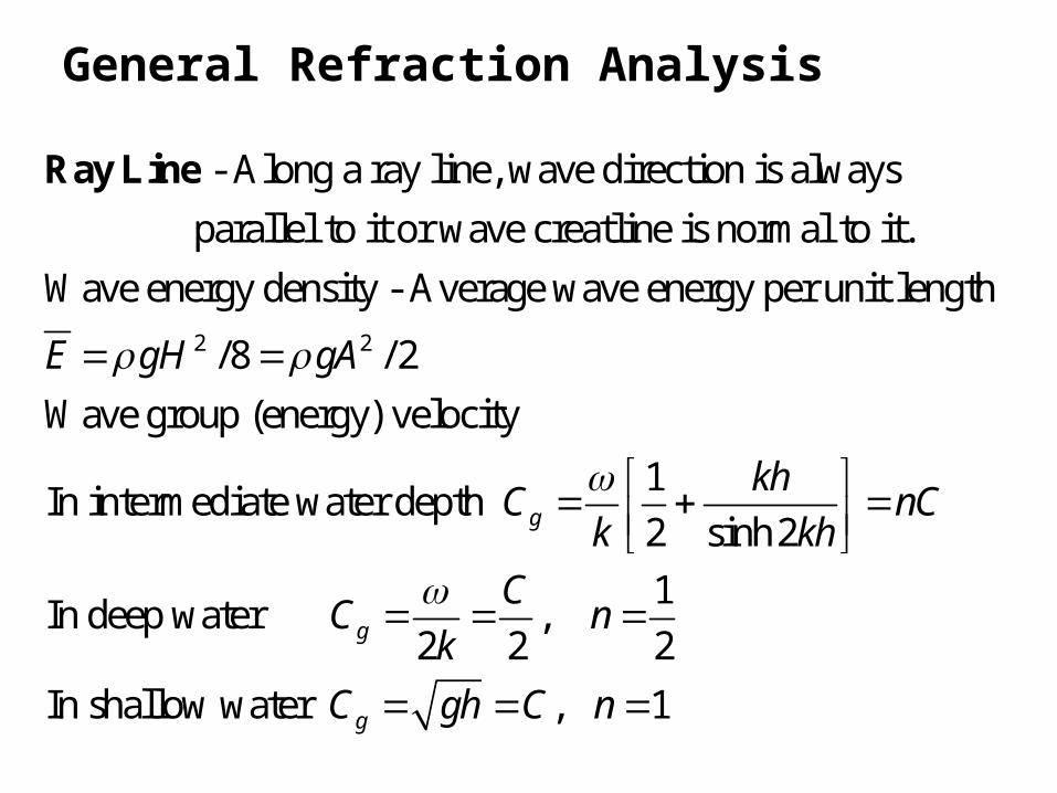
General Refraction Analysis
2 2
- Along a ray line, wave direction is always parallel to it or wave creatline is normal to it.Wave energy density - Average wave energy per unit length
/8 / 2Wave grouE gH gA
Ray Line
p (energy) velocity1In intermediate water depth 2 sinh 21In deep water ,
2 2 2In shallow water , 1
g
g
g
khC nCk kh
CC nk
C gh C n

1. Steady state (time-independent)2. Wave characteristics are inpendent of y (long shore direction)3. Bottom contours is paralell to the shore line which is striaght

0 10 0 1 1
0 0
1 0 0 0 0
0 1 1 1 1
11
00
Subscript '0 ' denotes it at 12
2
g g
g p
g p
g g
C E b C E b
C C
C b C bEC b C bE
H EH E
deep water
Wave energy flux =
Eenergy conservation (no wave breaking)gC E

11
00
0
1
0
1
, known as the refraction coeff.
, known as the shoaling coeff.2
S R
R
ps
g
H E K KH E
bKb
CK
C
pp117-118 (old edition pp91-92)

•Wave Diffraction: When wave energy is transferred laterally to wave direction, this phenomenon is known as wave diffraction.
Wave diffraction occurs when waves passing by a surface piercing body. It may occur in deep or shallow water.
An example in shallow water is wave diffraction behind a breaker water. See Fig. 4-22 at pp119 (old edition Fig. 4-13 at pp93). (internet examples)


•Wave Reflection and Transmission: when the water depth suddenly changes, part of the incident wave energy is reflected in the direction opposite to the incident wave direction, part energy continues to propagate (transmit) in the incident wave direction. : incident wave height; : reflected wave height : transmitted wave height
Reflection Coeff. ;
Transmission Coeff.
i r
t
rr
i
tt
i
H HH
HCHHCH

0
0
Reflection Coeff. of a plane slope tan
/
where is the slope is the incident wave height is the wavelength in deep water.
i
i
H L
HL
Surf parameter
Using Fig 4-23 at pp 120 (old edition Fig. 4-14 at pp 94), you may determine the reflection coefficient based upon the surf parameter.

Wave RunupWave runup is important to the design of the height of coastal structure, such as seawalls and breakwaters.
0
Hunt (1959)tan for tan 0.1
/
where is the wave runup. is the wave height see Fig. 4-24 (p121) (old edition Fig. 4-15 (p95))
RH H L
RH

Sediment Transport 3
2
s
Buoyancy index: 1
where the specific weight of a sphere the specific weight of fluid the diameter of sphere the kinematic viscosi
s s
s
gdB
d
50
ty of fluid.Because the diameter of the sediment is not uniform, is replace by , which is the median diameter of the sediment.
is non-dimensional.
sd d
B

Sediment Transport 3
2
3
Buoyancy index: 1
In general, 1, that is, the sediment particle is
heavier than water. The submerged weight of the
particle is proportional to and the falling velocitydecreas
s s
s
s
gdB
d
es with the increase in viscosity of water.Hence, smaller buoyancy index indicates smaller fallingvelocity and larger buoyancy index results in largerfalling velocity.

Based on the buoyancy index, the falling velocity (also known as terminal velocity) can be
computed using Eq. 4-26 (p125 old edition p101) or Fig 4-27 (p125) (old edition Fig. 4-18 (p102)). Falling
fV
velocity tells the suspension time of a particle in water after it is suspended in the water column.If one knows the current or wave induced particle velocity, the movement of the particle in the horizontaldirection can be computed.

Reading Assignment:
•Sediment Transport & Scour
•Littoral Transport (sediment transport in coastal or littoral zone)
•Coastal Structure (jetties, groins, breakwater, sand-bypass & G-tubes)
•Dredging

Reading Assignment:
•Sediment Transport & Scour
•Littoral Transport (sediment transport in coastal or littoral zone)
•Coastal Structure (jetties, groins, breakwater, sand-bypass & G-tubes)
•Dredging