co2report2
TRANSCRIPT

5/9/2018 co2report2 - slidepdf.com
http://slidepdf.com/reader/full/co2report2 1/97
REVIEW OF THE USE OF
CARBON DIOXIDE TOTAL FLOODINGFIRE EXTINGUISHING SYSTEMS
Robert T. Wickham, P.E.
August 8, 2003
WICKHAM ASSOCIATES

5/9/2018 co2report2 - slidepdf.com
http://slidepdf.com/reader/full/co2report2 2/97
NOTICE
This document is disseminated under the sponsorship of the U.S.Environmental Protection Agency in the interest of information exchange.The views expressed in this report are those of the author and do notnecessarily reflect those of the US Environmental Protection Agency.
The US Environmental Protection Agency does not assume liability forthe contents or use thereof and further the Agency does not endorseproducts or manufacturers. Trade or manufacturer's names appearherein solely because they are considered essential to the objective ofthis report.
The following commercial products (requiring a trademark designation ® or ™) are mentioned in this report. Due to the frequency of usage,trademarks are not indicated. Mention of a product does not constituteendorsement or rejection of the product.
Argonite
Argotec
FE-13
FE-25
FM-200
Inergen
NN100
Novec 1230
There are no restrictions on copying or distribution of this document.
An electronic copy of the report – in Adobe Acrobat portable documentformat - is available at http://rtwickham.home.comcast.net

5/9/2018 co2report2 - slidepdf.com
http://slidepdf.com/reader/full/co2report2 3/97
- i -
Preface
In March 2002 the Military Sealift Command (MSC) had a fatal accident1 involving acarbon dioxide total flooding fire extinguishing systems on its ship CAPE HORN.2 Thisfollowed another carbon dioxide total flooding fatal accident on a MSC sister ship, CAPEDIAMOND, in 1993.3 Each of those accidents caused the deaths of two persons.
The time has come to re-examine the practice of using carbon dioxide total floodingsystems in normally occupied spaces. This report considers the use of these types ofsystems in both the industrial and marine markets. Due to the considerable increase inthe use of carbon dioxide systems over other available systems in the marine sector, thisreport makes a special focus on the use of these types of systems in manned machineryspaces on merchant ships.
In the preparation of this report, I was able to interview over 70 people who have specificknowledge and often times strong opinions on the subject of the use of carbon dioxidetotal flooding systems. The contributions of these experts provide a broad spectrum ofviews on which this report is based. I acknowledge and thank all of these people for
their input, but add that I alone am responsible for the completeness and accuracy of theinformation in this report.
During the peer review process, several additional subjects were suggested. Theseincluded a discussion of mandatory discharge testing for carbon dioxide systems,assessments of reliability of carbon dioxide systems and the consideration of employingdetection and alarm systems only in lieu of carbon dioxide systems. These subjectswere considered beyond the scope of this report and are not included.
Five peer reviews were received and four were in agreement with the report. Onereviewer had reservations regarding nuanced language or emphasis but did dispute theprocess of arriving at conclusions in the report without the performance of a very broad-
based risk-benefit analysis. In response to this minority view, the report has beenchanged to reflect the reviewer's concerns regarding emphasis.
The minority reviewer's comments on risk-benefit focused on the point that there areboth reasonable and unreasonable exposures to injury or death and that an expansiverisk benefit analysis should be performed to establish which is the case for carbondioxide total flooding systems compared to other industrial equipment use. Thiscomment was rejected and the following explanation4 for that rejection was provided tothe minority reviewer:
1Cole, William, “Suffocation Likely In Ship's Two Fire Deaths,”Honolulu Advertiser, April 3, 2002.
2The CAPE HORN is owned by the United States as part of the Ready Reserve Force, a fleet of more than
90 vessels capable of transporting on short notice military cargo, fuel, equipment, munitions, and othersupplies in support of military forces. These ships are under the operational control of the United StatesNavy’s Military Sealift Command.
3“Carbon Dioxide as a Fire Suppressant: Examining the Risks,” Report EPA430-R-00-002, United States
Environmental Protection Agency, Washington, DC: February 2000.
4Letter from Ms. Bella Maranion to the minority reviewer, United States Environmental Protection Agency,
Washington, DC: July 14, 2003.

5/9/2018 co2report2 - slidepdf.com
http://slidepdf.com/reader/full/co2report2 4/97
- ii -
“In most risk benefit analyses, both the risk and the benefit accrue to the same party.In all of your examples of “drive a car rather than use public transportation, live in a highrise building rather than a single level house, purchase and store various poison chemicalsin the household, ….” the beneficiary of the risk has been the risk-taker him/herself.
In the case of carbon dioxide systems, the beneficiary of the risk and the risk taker are
nearly always different parties. The decision to employ carbon dioxide systems is nevermade by those who are ultimately exposed to the danger of death or injury. Instead it ismade by the owner or owner’s representative and it is to the owner that the benefit of a costsavings accrues. In this case, it is the workers or other persons exposed to the possibility ofan accidental discharge of the carbon dioxide system who assume the risk.
This is why it is a public safety issue. We have one segment of society (owners, owners’representatives, etc.) making decisions to use carbon dioxide systems in instances thatneedlessly expose an entirely different group of people. Thus I am afraid that the onlyconclusion a risk-benefit analysis would reach is that – from a public safety standpoint – thebalance between the risk and the benefit lies heavily or even entirely on the risk side.”
Several manufacturers provided engineering and cost information on their agents andsystems that served as the basis for the comparisons of alternatives in this report. Iwould like to acknowledge the following manufacturers for their input, without which thecomparisons could not have been made:
- 3M Performance Chemicals, St. Paul, Minnesota- Ansul Fire Protection, Marinette, Wisconsin- Dupont Fluoroproducts, Wilmington, Delaware- Fogtec Fire Protection, Hamburg, Germany- Great Lakes Chemical Corporation, West Lafayette, Indiana- Kidde-Fenwal, Inc., Ashland, Massachusetts- Marioff Corporation Oy, Vantaa, Finland
Most of all, I would like to thank the peer reviewers who spent countless hours on thisreport. I appreciate the time they took to review and comment on the report and thenearly unanimous support of the contents and conclusions:
- David V. Catchpole of Petrotechnical Resources Alaska5 - Robert Darwin, P.E. of Hughes Associates, Inc.- Jeffrey L. Harrington, P.E. of the Harrington Group, Inc.- Normal W. Lemley, P.E. of the Center for Maritime Leadership, Inc.- Thomas Wysocki of Guardian Services, Inc.
Robert T. Wickham, P.E.August 8, 2003
**********
5In addition, I would like to acknowledge the contribution of two of Mr. Catchpole’s associates in the peer
review process. Richard Coates of BP and Niall Ramsden of Resource Protection International providedvaluable input and I appreciate their efforts as well.

5/9/2018 co2report2 - slidepdf.com
http://slidepdf.com/reader/full/co2report2 5/97
- iii -
Table of Contents
Preface ..............................................................................................................................i
Table of Contents........................................................................................................... iii
List of Tables...................................................................................................................v
List of Figures ................................................................................................................vi
1 Introduction ............................................................................................................1 2 Objective of Report ................................................................................................3 3 Methodology...........................................................................................................4 4 Conclusions............................................................................................................ 5
4.1 Personnel Safety .............................................................................................5 4.2 Performance....................................................................................................5 4.3 Training ...........................................................................................................5 4.4 Cost .................................................................................................................6
4.5 Alternatives......................................................................................................6 4.6 Technology......................................................................................................6 4.7 Use Controls....................................................................................................7
5 Recommendations.................................................................................................8 5.1 Use Conditions ................................................................................................8 5.2 Approach .........................................................................................................8
6 Background ............................................................................................................9 6.1 History of Carbon Dioxide Fire Extinguishing Systems ...................................9 6.2 Carbon Dioxide Performance in Marine Systems............................................ 9 6.3 Health Risk ....................................................................................................10 6.4 Adverse Health Effect....................................................................................10 6.5 Accident Record............................................................................................11
6.6 Recent Accidents ..........................................................................................12 6.7 Accident Focus and Reporting ...................................................................... 15
7 Types of Carbon Dioxide Extinguishing Systems ............................................ 16 7.1 Agent Storage Configurations .......................................................................16 7.2 Methods of Application ..................................................................................16
7.2.1 Total Flooding ..................................................................................16 7.2.2 Local Application..............................................................................16
7.3 Mechanism of Extinguishment.......................................................................17 8 Applications..........................................................................................................18
8.1 Marine Market ...............................................................................................19 8.1.1 International Marine Market.............................................................21 8.1.2 United States Marine Market ...........................................................24
a. Commercial Ships........................................................................24 b. Military Ships ...............................................................................24 8.2 Industrial Market............................................................................................26
9 Standards and Regulations.................................................................................29 9.1 U.S. Environmental Protection Agency .........................................................29 9.2 U.S. Coast Guard..........................................................................................30 9.3 National Fire Protection Association..............................................................33
9.3.1 NFPA 12 ..........................................................................................34 9.3.2 NFPA 2001 ......................................................................................35
9.4 Occupational Safety and Health Administration............................................ 37

5/9/2018 co2report2 - slidepdf.com
http://slidepdf.com/reader/full/co2report2 6/97
- iv -
9.5 International Standards Organization............................................................37 9.6 International Maritime Organization...............................................................38
10 Alternatives...........................................................................................................41 10.1 General..........................................................................................................41 10.2 Gaseous Extinguishing Agents for Fixed Systems........................................42 10.3 Water Mist Systems ......................................................................................43
10.4 Other Types of Agents for Fixed Systems.....................................................44 10.4.1 Inert Gas Generators.......................................................................44 10.4.2 Aerosols...........................................................................................44
11 Comparisons of Alternatives ..............................................................................46 11.1 General..........................................................................................................46 11.2 Types of Comparisons...................................................................................46
11.2.1 Adequate or Inadequate..................................................................46 11.2.2 Preferences .....................................................................................47 11.2.3 Quantifiable Comparisons ...............................................................47
11.3 Space, Weight and Cost Comparisons..........................................................48 11.3.1 System Design Results ...................................................................50 11.3.2 System Weight Comparisons ..........................................................52
11.3.3 System Footprint Comparisons .......................................................52 11.3.4 System Cube Comparisons.............................................................53 11.3.5 Cost Comparisons...........................................................................54 11.3.6 Cost Comparison Exceptions .......................................................... 56
a. Selector Valve Systems...............................................................56 b. Bulk Storage Systems .................................................................57 c. Combined Use Systems ..............................................................57
11.3.7 Overall Comparisons and Ranking..................................................58 12 Perceived Issues..................................................................................................60
12.1 Personnel Safety ...........................................................................................60 12.1.1 Safe enough....................................................................................60 12.1.2 Unsafe under any conditions...........................................................61
12.2 Performance..................................................................................................61 12.2.1 Carbon dioxide is unique.................................................................61 12.2.2 Other agents can do the same ........................................................61
12.3 Training .........................................................................................................62 12.3.1 Training is the answer .....................................................................62 12.3.2 Training is a good idea, but not the answer.....................................62
12.4 Cost and Availability ......................................................................................62 12.4.1 Low cost is great..............................................................................62 12.4.2 You get what you pay for .................................................................62
12.5 Alternatives....................................................................................................63 12.5.1 Alternatives have problems .............................................................63 12.5.2 Sure, but don’t rule them out ...........................................................63
12.6 Technology....................................................................................................63
Appendix A – Search Results – Engine Room Fires .................................................65
Appendix B – OSHA Technical Bulletin......................................................................68
Appendix C - Excerpt from NFPA Standard 12 ..........................................................71
Appendix D - Excerpt from NFPA Standard 2001 ......................................................76

5/9/2018 co2report2 - slidepdf.com
http://slidepdf.com/reader/full/co2report2 7/97
- v -
Appendix E - Excerpt from OSHA Regulations ..........................................................80
Appendix F - Excerpt from ISO Standard 6183 ..........................................................84
Appendix G - Excerpt from IMO FSS Code.................................................................86
Appendix H – Proposal for NFPA 12 ...........................................................................88
List of Tables
Table 1: Interviewees for this Report ...............................................................................4
Table 2: Search Results Shipboard Engine Room Fires and Carbon Dioxide Systems 10
Table 3: Acute Health Effects of High Concentrations of Carbon Dioxide .....................11
Table 4: Death And Injury Incidence Reports ................................................................11
Table 5: Causes of Injuries and Deaths Associated with Carbon Dioxide Discharges ..12 Table 6: Additional Death And Injury Incidents in the US and Mexico...........................13
Table 7: Additional Death And Injury Incidents in Japan................................................14
Table 8: Marine Applications for Carbon Dioxide Total Flooding Systems ....................19
Table 9: Alternatives to Marine Carbon Dioxide Total Flooding Systems ......................19
Table 10: Top 20 Merchant Fleets of the World.............................................................21
Table 11: Age Profile of the World Merchant Fleet Greater than 100 Gross Tons ........22
Table 12: Annual 2002 Net Change in the World Merchant Fleet Count .......................22
Table 13: World Commercial Ship Order Book..............................................................23
Table 14: Engine Room Protection on US Commercial Ships Under Construction, ......24
Table 15: Sampling of Major Military and USCG Vessel Projects.................................. 25
Table 16: Top Industrial Applications for Carbon Dioxide Total Flooding Systems .......27
Table 17: Alternatives to Carbon Dioxide Total Flooding Systems................................27
Table 18: USCG Regulations for Carbon Dioxide Fire Extinguishing Systems .............31
Table 19: USCG Safety Provisions for Carbon Dioxide Fire Extinguishing Systems..... 32
Table 20: Alternatives to Halons - Expectations versus Reality.....................................41
Table 21: Gaseous Alternatives to Carbon Dioxide for Total Flooding Systems ...........43
Table 22: Organizations Developing Guidelines for Aerosol Systems........................... 45
Table 23: IMO Requirements for Machinery Space Total Flooding Systems ................ 48
Table 24: Protected Space Characteristics....................................................................49
Table 25: Design Parameters for the Gaseous Agent Systems..................................... 50
Table 26: System Design Results for 500 m3 Systems..................................................51
Table 27: System Design Results for 1,000 m3 Systems...............................................51

5/9/2018 co2report2 - slidepdf.com
http://slidepdf.com/reader/full/co2report2 8/97
- vi -
Table 28: System Design Results for 3,000 m3 Systems...............................................51
Table 29: System Design Results for 5,000 m3 Systems...............................................51
Table 30: % Weight Comparisons of Systems in 500 – 5,000 m3 Range of Volumes....52
Table 31: % Footprint Comparisons of Systems in 500 – 5,000 m3 Range of Volumes.53
Table 32: % Cube Comparisons of Systems in 500 – 5,000 m3 Range of Volumes......54
Table 33: $ Cost Comparisons of Systems in 500 – 5,000 m3 Range of Volumes.........55
Table 34: % Cost Comparisons of Systems in 500 – 5,000 m3 Range of Volumes .......56
Table 35: Equipment Costs of Incorporating IMO MSC/Circ. 913 System..................... 57
Table 36: % Comparisons of Average Values over the 500 to 5,000 m3 Range ............58
Table 37: Ranking of Average Values over the 500 to 5,000 m3 Range of Volumes......58
List of Figures
Figure 1: System Weight Comparisons..........................................................................52
Figure 2: System Footprint Comparisons.......................................................................53
Figure 3: System Cube Comparisons ............................................................................54
Figure 4: $ Cost Comparisons of Systems in the 500 - 5,000 m3 Range of Volumes....55
**********

5/9/2018 co2report2 - slidepdf.com
http://slidepdf.com/reader/full/co2report2 9/97
- 1 -
1 Introduction
In 2000, the US Environmental Protection Agency (EPA) published a report6 on the risksof carbon dioxide systems which enumerated many of the injuries and deaths associatedwith carbon dioxide total flooding extinguishing systems used in industrial and marine
fire protection applications. That same report made special note of the fact that themarine industry had the most injuries and fatalities from these systems.
The deployment of new carbon dioxide systems began to decline with the increase incommercial acceptance7 of halon 1301 systems in the early 1970s. Over the next twodecades, halon 1301 became the system of choice for many industrial fire protectionapplications and for new ships and boats. One important reason was that the halon1301 systems cost less than carbon dioxide systems. In addition to cost, halon 1301, atthe concentrations used for effective extinguishment, was not lethal to persons in theprotected spaces.
In the late 1980s and early 1990s, the problem of depletion of the stratospheric ozone
layer was recognized, the Montreal Protocol was ratified, and the Clean Air Act in theU.S. required the production phase-out of halons, a potent ozone-depletor. Many in thefire protection industry thought this situation did not pose a problem as a whole portfolioof alternatives was available ranging from halocarbons, inert gases, water mist andaerosol extinguishing agent systems. The industry focused its efforts on bothcommercialization of the alternatives and developing the necessary standards and testprotocols to provide guidelines for the safe use of the new agents.
To support the U.S. transition away from halons, the US EPA developed the SNAP8 listwhich served as a vehicle to provide guidance to the public about the human health andenvironmental effects of the alternative total flooding agents and any conditions for usesuch as suitability for use in normally occupied or limited to use in normally unoccupiedspaces.9 The distinction between the two is rather conservative, but those agents thatfailed to achieve the approval for use in normally occupied spaces invariably ended upon the trash pile of abandoned agents.
6“Carbon Dioxide as a Fire Suppressant: Examining the Risks,” Report EPA430-R-00-002, United States
Environmental Protection Agency, Washington, DC: February 2000.
7“Guide to Fixed Fire Fighting Equipment Aboard Merchant Vessels, Change 1: Halon Systems,” Navigation
and Vessel Inspection Circular NVIC 6-72, U.S. Coast Guard, Washington, DC: August 22, 1972.
8“United States Environmental Protection Agency SNAP Program,” Title 49, Code of Federal Regulations,
Part 111.59, Sub-Chapter J, Federal Register, Volume 59, Page 13044. Under section 612 of the Clean AirAct, EPA established the Significant New Alternatives Policy (SNAP) Program. SNAP's mandate is toidentify alternatives to ozone-depleting substances and to publish lists of acceptable and unacceptablesubstitutes. Several rules and notices have expanded these lists, and they are available for online reading
or for downloading ( http://www.epa.gov/ozone ). In addition, fact sheets cover more fully the eight industrialuse sectors included within SNAP. Finally, information about enforcement actions is available.
9 The NFPA Glossary of Terms (available at http://www.nfpa.org/PDF/definitions.pdf?src=nfpa) defines“occupiable area,” “occupiable story” and “unoccupied building.” However, those terms are used individuallyin three different standards (NFPA 72, 101B and 1124 respectively), so a clear differentiation is not obvious.The draft standard for aerosol extinguishing systems (proposed NFPA 2010) has provided the followingside-by-side definitions: Normally Occupied : An area or space where, under normal circumstances,persons are present. Normally Unoccupied : An area or space not normally occupied by people but whichmay be entered occasionally for brief periods. Unoccupiable : An area or space which cannot be occupieddue to dimensional or other physical constraints.

5/9/2018 co2report2 - slidepdf.com
http://slidepdf.com/reader/full/co2report2 10/97
- 2 -
Little did we know at that time that one of the agents that would play a significant role asa halon alternative would be carbon dioxide. Carbon dioxide is in fact on the SNAP listas a suitable alternative to halons in total flooding applications. Unlike other agents thatmay have “use conditions” or “narrowed use limits” attached, there are no restrictions oncarbon dioxide. However, the EPA obviously does recognize the dangers of the use ofcarbon dioxide when they published the previously cited report on its risks and
specifically pointed out …..“Appropriate precautions must be taken before switching to carbon dioxidesystems and with this report EPA attempts to raise awareness and promotethe responsible use of carbon dioxide fire suppression systems.”

5/9/2018 co2report2 - slidepdf.com
http://slidepdf.com/reader/full/co2report2 11/97
- 3 -
2 Objective of Report
The objective of this report is to provide information and guidance to the US EPA, othergovernment agencies, the US fire protection industry, end users and the public on theadvisability of the use of carbon dioxide total flooding systems in normally occupied
spaces. This report considers the use of carbon dioxide systems in the industrial andmarine markets with a special focus on the growing use in this latter market.
Specific goals of the report are:
• Provide an overview of past and current experience with carbon dioxide totalflooding systems with a focus on the life safety aspects of their use.
• Outline the relevant regulations and standards that provide guidance on the safeemployment of carbon dioxide total flooding systems.
• Develop comparisons of carbon dioxide with other halon alternatives to includeconsideration of system weight, system space requirements and system costs.
•Provide a discussion of issues related to changes in use conditions for carbondioxide total flooding systems.
• Provide specific recommendations on the need for use conditions, if any, and thenature of those use conditions.
**********

5/9/2018 co2report2 - slidepdf.com
http://slidepdf.com/reader/full/co2report2 12/97
- 4 -
3 Methodology
The methodology for assembling the information contained in the report consisted of twoelements: (1) research of published documents, all of which are referenced in the reportand (2) personal or telephone interviews with individuals with specific knowledge in the
field of fire extinguishing agents and systems – including carbon dioxide and thealternatives to carbon dioxide.
Table 1 is an illustration of the affiliations and the number of interviewees who wereconsulted for their views on the subject of the use of carbon dioxide systems.
Table 1: Interviewees for this Report
Affiliation of IntervieweeNumber of
Interviewees inthis Category
Architect or Engineering Firm 8
Associations & Societies 13
End User 16Federal Regulator 10
Fire Extinguishing Agent Manufacturer 6
Fire Extinguishing Systems Installer 3
Fire Extinguishing Systems Manufacturer 11
Fire and Accident Statisticians 6
Insurance Industry 3
TOTAL 76
**********

5/9/2018 co2report2 - slidepdf.com
http://slidepdf.com/reader/full/co2report2 13/97
- 5 -
4 Conclusions
4.1 Personnel Safety
• The number of injuries and deaths from carbon dioxide total flooding systems arewell known. The obvious proliferation of total flooding carbon dioxide systems atrates heretofore unseen in the marine market will certainly result in a directlyproportional increase in injuries and deaths from this agent.
• When viewed individually, the reported accidents involving carbon dioxide totalflooding systems could each be rationalized as unfortunate but somehowunrelated events. However, looking at the record of carbon dioxide systems intotal, (even with incomplete information) it is difficult to accept that enough isbeing done to protect the public.
• With the exception of the US EPA and the US Coast Guard, there is not anotherstandards making organization or regulatory body, nationally or internationally,that has done anything of substance to reduce the incidents of death and injurycaused by carbon dioxide systems.
• It is technically indefensible that standards and regulatory organizations employrigorous review standards to assure that the new halon alternatives (includinghalocarbons, inert gases and aerosols) are safely employed in normally occupiedspaces while seemingly relegating a lower level of scrutiny to the use of carbondioxide systems at lethal concentrations in spaces where personnel may beexposed.
• The fundamental fact remains that carbon dioxide is inherently lethal – accidentaldischarges of carbon dioxide total flooding systems can kill and have killed.
4.2 Performance
• Unquestionably, the advent of total flooding systems in general (halons, carbondioxide, halocarbons, inert gases, aerosols, and water mist) have truly benefitedsociety by saving untold numbers of lives and property over the last half centuryand continuing to perform this service today.
• Contrary to widely held beliefs within the industry that carbon dioxide systemsare unique and cannot be replaced by other systems, the facts are that there areseveral extinguishing agent systems that perform as well as or better than carbondioxide in the most frequent applications.
• In the absence of carbon dioxide, no technical reason exists to forestall testing ofmany of the already commercialized alternatives to service those fewapplications where carbon dioxide today seems to be the exclusive solution in
some industrial applications.
4.3 Training
• As the most frequent cause of accidental discharges of carbon dioxide systemsinvolve maintenance activities on or around the carbon dioxide systems, trainingfor maintenance and service people must be emphasized and consistentlyemployed to stress the dangers of these systems.

5/9/2018 co2report2 - slidepdf.com
http://slidepdf.com/reader/full/co2report2 14/97
- 6 -
• At the same time, training does not seem to be a high priority for many of theseorganizations as funding for this type of activity is difficult to secure, especiallywhen compared to all the other discretionary spending needs of an organization.
• In the marine sector, training is an especially difficult issue due to continuingconcern being expressed, and not just by unions, about the effect of the
reduction in crew sizes and the resultant reduction in the combined knowledgeand expertise of the crews.
4.4 Cost
• The cost of the alternatives compared to carbon dioxide systems are a realbarrier to acceptance. The most cost-effective alternative systems rangebetween 55% to 65% more than the cost of carbon dioxide systems. Otheralternative systems cost as much as 130%+ more than the carbon dioxidesystems.
• The cost difference between the carbon dioxide systems and the alternatives isexacerbated by the fact that carbon dioxide systems cost anywhere between
100% and 180% more than halon 1301 systems which carbon dioxide isreplacing in the marine sector.
4.5 Alternatives
• The choice of a fire suppression flooding system is based on several factors. Inthe case of carbon dioxide systems, cost apparently eclipses all otherconsiderations to the detriment of sound safety and performance decisions.
• In the marine sector, the shipowners, classification societies, shipyards,architects and regulators report there are (1) too many alternatives for them tosort through, (2) too much negative information being spread about competitiveproducts and (3) too little energy by the fire protection industry to provide whatthe marine sector needs: a safe, cost-effective replacement for halons and, bydefault, carbon dioxide systems.
• The review of the new alternatives incorporates the latest scientific knowledgeand technological expertise on safe human exposure, environmental effects andsystem performance to determine appropriate applications and restrictions onapplications of these systems. The same rigor has not been applied to carbondioxide systems.
4.6 Technology
• The output of research and development efforts to provide alternatives to halon
1301, and by inference carbon dioxide, have met the safety, fire protection andenvironmental goals but have completely missed the cost goals for the majorityof users, especially in the marine sector.
• The level of effort going into developing alternatives technologies to carbondioxide and halon 1301 must be intensified, both in the search for new chemicalbased agents and/or the development of more cost-effective agent storage anddelivery systems for naturally occurring agents such as water and inert gases.

5/9/2018 co2report2 - slidepdf.com
http://slidepdf.com/reader/full/co2report2 15/97
- 7 -
4.7 Use Controls
• The notion of use controls on carbon dioxide total flooding systems would receivethe support of some and opposition from many. There are also significantnumbers of those who are undecided or have not expressed an interest in thesubject.
• Those who would oppose use controls generally have an economic stake in thematter. As a group they dislike carbon dioxide systems, but they have an evengreater dislike for the costs of the alternative systems. For many, the oppositionwould disappear with a solution to the cost problem.
**********
5/9/2018 co2report2 - slidepdf.com
http://slidepdf.com/reader/full/co2report2 16/97
- 8 -
5 Recommendations
5.1 Use Conditions
Based on historical data of use and current industry practices and priorities, carbondioxide total flooding systems should be subjected to the same use limitations imposedon the agents contained in NFPA Standard 200110, ISO Standard 1452011 and IMO MSCCircular 848.12
These standards incorporate the most current information and scientific knowledge onsafe human exposure, environmental impacts and system design and performance asrecognized in the various sectors of use in the fire protection industry. These standardsand regulations define current industry practices to assure the highest level of safety forthe use of fire suppression agents.
To adopt a consistent level of safety, the following restriction should be placed on theuse of carbon dioxide systems in all standards and regulations:
Carbon dioxide total flooding systems shall not be used in normally occupiedareas.
5.2 Approach
While the EPA’s options are numerous, ranging from public education up through directregulation, it is recommended that the EPA support the adoption of the suggested userestriction through the consensus standards’ making process of the National FireProtection Association (NFPA).
The EPA has demonstrated, through its direct participation in several NFPA technicalcommittees, that the agency works well within the framework of this standards makingorganization to support the work of these committees related to issues of environmentalprotection and public safety. The introduction of this subject has been made with aproposal to NFPA that NFPA 1213 be modified to prohibit the use of carbon dioxide totalflooding systems in spaces that are normally occupied. (See Appendix H).
**********
10"NFPA 2001 - Standard on Clean Agent Fire Extinguishing Systems - 2000 Edition," National Fire
Protection Association, Quincy, MA: February 2000.11
"International Standard on Gaseous Fire-Extinguishing Systems," ISO 14520-1 through 14520-15,available from Standards Association of Australia, GPO Box 5420, Sydney, NSW 2001, Australia: August2000.
12"Revised Guidelines for the Approval of Equivalent Fixed Gas Fire-Extinguishing Systems, as Referred to
in SOLAS 74, for Machinery Spaces and Cargo Pump Rooms," Annex to IMO Maritime Safety CommitteeCircular 848, International Maritime Organization, 4 Albert Embankment, London SE1 7SR, England: June1998.
13“NFPA 12 - Standard on Carbon Dioxide Extinguishing Systems – 2000 Edition,” National Fire Protection
Association, Quincy, MA February 2000.

5/9/2018 co2report2 - slidepdf.com
http://slidepdf.com/reader/full/co2report2 17/97
- 9 -
6 Background
6.1 History of Carbon Dioxide Fire Extinguishing Systems
Carbon dioxide systems have been in use since the early 1900’s and in the late 1920’swork began on the first NFPA standard describing the use of these systems. From thatpoint until the late 1960’s, carbon dioxide was for all practical purposes the only gaseousextinguishing agent in wide commercial use. It was during that time period that societyapparently became accustomed to the notion that employing a fire extinguishing systemwith inherent serious life safety consequences was nothing more than a trade-off andwell worth the risk in light of the fire protection benefits derived.
In the early 1970’s carbon dioxide total flooding systems somewhat fell from favor withthe introduction of the halons, and specifically halon 1301 systems. Halon 1301, with itsinherent life safety characteristics coupled with the fact that the new systems were lessexpensive than high pressure carbon dioxide systems, virtually left carbon dioxide fewerand fewer places to be applied. During the period of the early 1970’s until the late1980’s, the use of carbon dioxide systems was relegated to applications where (1) halon
1301 was clearly inappropriate or where (2) the promoters of halon 1301 chose not tomarket that agent. The most obvious of these were local application systems, an areanever seriously pursued with halon 1301; applications with a deep seated Class A firepotential, like shipboard cargo holds; and applications where decomposition of halon1301 would be problematical, like in ovens. Another area virtually reserved for carbondioxide in that time frame were applications than needed so much agent thatrefrigerated, bulk storage, low pressure carbon dioxide systems were the economicalchoice.
In general, a good rule of thumb was if you are going to experience a lot of systemdischarges, it was wiser to invest in a carbon dioxide system where the cost of rechargewas much less that that of a halon 1301 system. Otherwise, if the fire extinguishing
system was employed to protect high value hazards with a low probability of fire, thelower initial cost, safer halon 1301 system became the preferred selection.
With the 1994 production and import ban on newly produced halons and even with theintroduction of new halon alternatives, we have seen an increase in the use of carbondioxide fire extinguishing systems, especially in the marine market. The resurgence inthe use of carbon dioxide in the marine market is very visible since shipbuilding is ahuge market for fire protection systems and the procurements and buying preferencesare apparent. In other markets, such as industrial and commercial, changes in carbondioxide system preferences and usage is not that obvious.
6.2 Carbon Dioxide Performance in Marine Systems
In trying to quantify the historical performance of carbon dioxide systems, it was foundthat statistics are just not available. However, it was possible to derive a sense of theperformance by looking at the marine market and searching the Lloyd’s List casualtyarchive14 for shipboard engine room incidents of fire involving carbon dioxide systems.
14The Archive is a source for marine casualty information on the web. It contains complete record of all
reports in Lloyd's List Casualty Page since January 1991. The search engine offers a number of tools towork across the full text of the casualty database and can be accessed at http://www.lloydscasualty.com

5/9/2018 co2report2 - slidepdf.com
http://slidepdf.com/reader/full/co2report2 18/97
- 10 -
The search covered the period from January 1991 through November 2002 andidentified 56 articles describing the same number of fire incidents within the scope of thesearch parameters. Some of the articles were better than others with respect toproviding meaningful information. Table 2 is an illustration of the information derivedfrom the articles. Appendix A contains an expanded table summarizing the individualincidents.
Table 2: Search Results Shipboard Engine Room Fires and Carbon Dioxide Systems(January 1991 through November 2002)
System Performance Number of Incidents Comments
Successful 39The carbon dioxide system successfullyextinguished the engine room fire.
Unclear 5The articles mentioned that the carbondioxide system was employed but neverdescribed the outcome
Irrelevant 4
While these articles were picked up in thesearch, the systems involved were actuallywater mist and halon, halon and foam andhalon alone, all of which operatedsuccessfully.
Unacceptable 8
The performance of the carbon dioxidesystem was unacceptable either because itwas not able to be discharged or the systemfailed to extinguish the fire once it wasdischarged.
In reviewing the information in Table 2, unless the Lloyd’s List casualty archive missesmost or even many of the engine room fires and related carbon dioxide system releases,56 discharges of engine room systems over a period of 12 years is less than five peryear.
6.3 Health Risk
During the research for this study it was surprising to find how many people weremisinformed about the range and extent of adverse health effects of exposure to largeconcentrations of carbon dioxide. Many believe that the cause of injury and death was asimple matter of hypoxia (reduced oxygen) similar to what one would expect with aninert gas (nitrogen, argon or blends of the same). In fact, carbon dioxide is anything butinert. It is toxic and it causes injuries and death by interfering with the functions of thecentral nervous system.
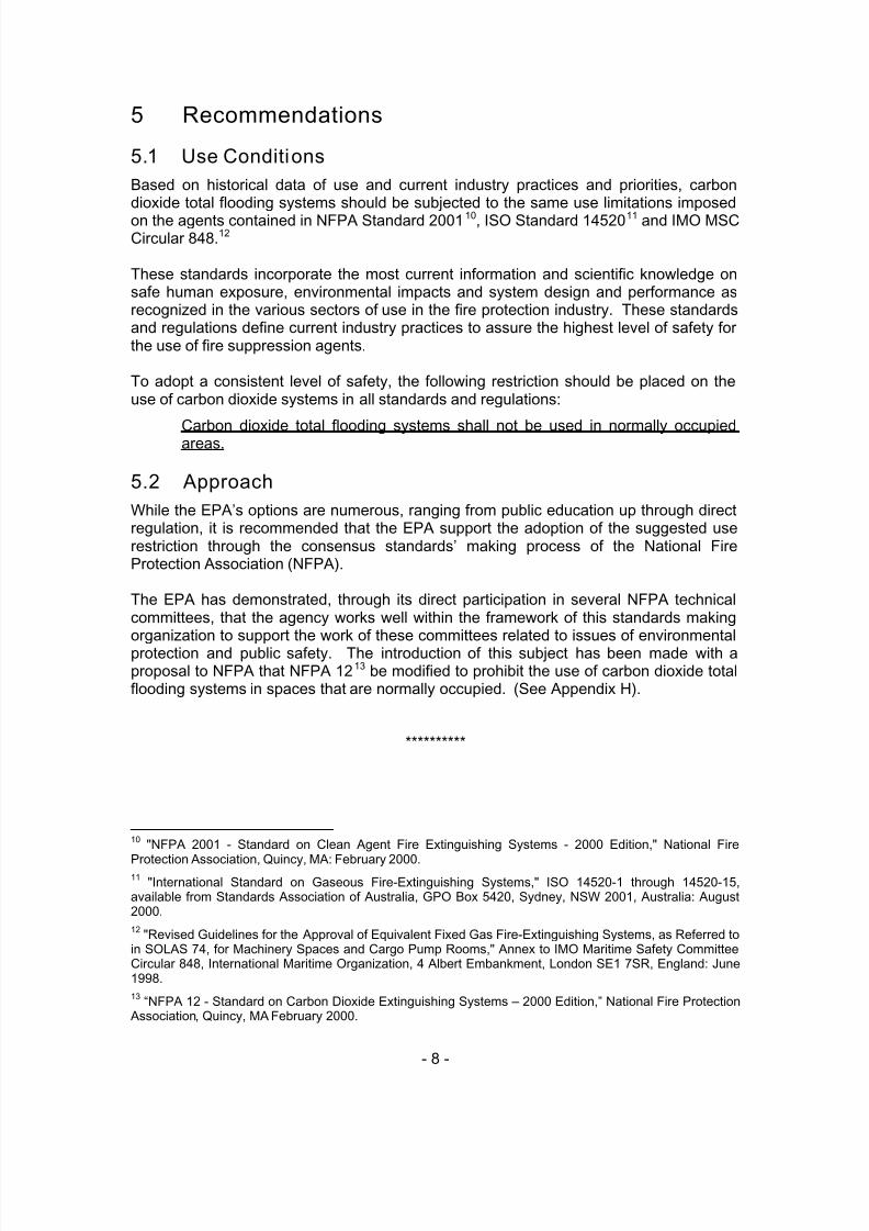
6.4 Adverse Health Effect
Table 3 illustrates the progressive adverse health effects from exposure to increasinglevels or ranges of carbon dioxide. Since most carbon dioxide total flooding systems aredesigned to produce concentrations ranging upwards from 34%, it is clear that carbondioxide is lethal far below the concentrations employed in total flooding fire extinguishingsystems.
5/9/2018 co2report2 - slidepdf.com
http://slidepdf.com/reader/full/co2report2 19/97
- 11 -
Table 3: Acute Health Effects of High Concentrations of Carbon Dioxide15
(With Increasing Exposure Levels of Carbon Dioxide)
Concentration
(% Carbon Dioxide/Air)Time Effects
2% Several hours Headache, dyspnea upon mild exertion.
3% 1 hour
Dilation of cerebral blood vessels, increased
pulmonary ventilation, and increasedoxygen delivery to the tissues.
4 – 5% Within a few minutesMild headache, sweating and dyspnea atrest.
6%
1 – 2 minutes
<16 minutes
Several hours
Hearing and visual disturbances
Headache and dyspnea
Tremors
7 – 10%
Few minutes
1.5 minutes – 1 hour
Unconsciousness or near unconsciousness.
Headache, increased heart rate, shortnessof breath, dizziness, sweating, rapidbreathing.
10 - 15% 1+ minuteDizziness, drowsiness, severe muscletwitching and unconsciousness.
17 – 30% < 1 minuteLoss of controlled and purposeful activity,unconsciousness, convulsions, coma anddeath.
6.5 Accident Record
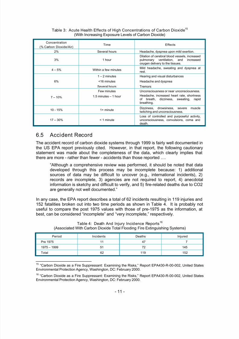
The accident record of carbon dioxide systems through 1999 is fairly well documented inthe US EPA report previously cited. However, in that report, the following cautionarystatement was made about the completeness of the data, which clearly implies thatthere are more - rather than fewer - accidents than those reported ….
“Although a comprehensive review was performed, it should be noted that datadeveloped through this process may be incomplete because: 1) additionalsources of data may be difficult to uncover (e.g., international incidents), 2)records are incomplete, 3) agencies are not required to report, 4) anecdotalinformation is sketchy and difficult to verify, and 5) fire-related deaths due to CO2are generally not well documented.”
In any case, the EPA report describes a total of 62 incidents resulting in 119 injuries and152 fatalities broken out into two time periods as shown in Table 4. It is probably notuseful to compare the post 1975 values with those of pre-1975 as the information, atbest, can be considered “incomplete” and “very incomplete,” respectively.
Table 4: Death And Injury Incidence Reports16
(Associated With Carbon Dioxide Total Flooding Fire Extinguishing Systems)
Period Incidents Deaths InjuredPre 1975 11 47 7
1975 – 1999 51 72 145
Total 62 119 152
15 “Carbon Dioxide as a Fire Suppressant: Examining the Risks,” Report EPA430-R-00-002, United StatesEnvironmental Protection Agency, Washington, DC: February 2000.
16“Carbon Dioxide as a Fire Suppressant: Examining the Risks,” Report EPA430-R-00-002, United States
Environmental Protection Agency, Washington, DC: February 2000.

5/9/2018 co2report2 - slidepdf.com
http://slidepdf.com/reader/full/co2report2 20/97
- 12 -
Of the 51 incidents during the period of 1975 through 1999, there was enoughinformation on 35 incidents to broadly categorize their causes or circumstances. Table 5is an illustration of the general circumstances surrounding these accidents, clearlyillustrating that maintenance activities – either on the system or in the vicinity of thesystem – are most associated with these incidences of system discharges.
Table 5: Causes of Injuries and Deaths Associated with Carbon Dioxide Discharges17 (1975 - 1999)
Type Discharge Circumstances Incidents Deaths Injured
During Maintenance onthe CO2 System
9 8 10
During Maintenancenear the CO2 System
8 19 19
During Testing 1 2 6
Accidental During Fire Situation 2 10 7
Faulty Component or
Installation2 4 13
Operator Error 2 1 4
False Alarm 2 1 15
During Testing orTraining
3 2 2
Intentional During Fire Situation 5 15 8
False Alarm 1 2 1
Total 35 64 85
6.6 Recent Accidents
In the preparation of this report, many inquiries were made to identify additional carbondioxide total flooding system incidents resulting in death or injury. The sameobservations as made in the EPA report are made here, about the difficulty of identifyingand confirming accidents from official sources. Further, in the US, it seems that there isa significant lag in time between the date of an incident and the time that it appears in anofficial data base managed by OSHA, the USCG or some other agency.
Notwithstanding that, Table 6 is a listing of several additional accidents that haveoccurred in North America since the publication of the EPA report.
17“Carbon Dioxide as a Fire Suppressant: Examining the Risks,” Report EPA430-R-00-002, United States
Environmental Protection Agency, Washington, DC: February 2000.

5/9/2018 co2report2 - slidepdf.com
http://slidepdf.com/reader/full/co2report2 21/97
- 13 -
Table 6: Additional Death And Injury Incidents in the US and Mexico
(Associated With Carbon Dioxide Total Flooding Fire Extinguishing Systems)
EventDate
Source Deaths Injuries Summary
07/27/2000
OSHA
TechnicalInformationBulletin
12/22/2001
1 0
“…. an employee of a securities firm diedfrom CO2 intoxication. The employee
was inside the vault with the vault doorclosed and locked. When the employeepulled a manual fire alarm actuationdevice that was located inside the vaultspace, it activated the warning alarm andthe total flooding CO2 system.”
02/20/2002
Mr. DonaldMurray
Ansul
03/31/2003
2 multiple
A carbon dioxide system prematurelyconnected and manually discharged inerror by workers aboard a ship at theMexican Navy Shipyard in Salina CruzOaxaca Mexico. The engine room wasoccupied at the time by many workers asship was being overhauled.
03/31/2002HonoluluAdvertiser
04/03/2002
2 0
Two civilian crew members died on the750-foot Ready Reserve Force shipCape Horn from apparent suffocation
when a fire was put out in the engineroom, officials said. "The possibility isthat it may have been as a result of a firesuppression system ….. Thesuppression systems replace oxygenwith carbon dioxide to smother a fire.”
01/19/2003
AssociatedPress
01/31/2003
2 0
“A couple found dead aboard theirdocked 58-foot yacht apparentlysuffocated when a fire suppressionsystem was accidentally set off, using upall the oxygen in the yacht. Marineexperts have determined that JohnRobertson, a leg amputee who wasn'twearing his prosthesis, fell and grabbeda wire that triggered the carbon dioxidepowered fire - suppression system.
Andreija was overcome by lack ofoxygen when she probably tried torescue her 260-pound husband. Thecouple was cleaning the yacht's engineroom and had begun painting it when theaccident happened, police said.”
A request to many contacts around the world to document accidents with injuries and / or deaths from total flooding carbon dioxide systems resulted in input only fromassociates in Japan. In its 2000 report, the US EPA had listed 7 accidents resulting in 4deaths and 14 injuries in Japan. The recent request for any new or additionalinformation produced a report of another 4 accidents in Japan resulting in 3 deaths and11 injuries. That information is illustrated in Table 7.
With his report of the accidents, Mr. Matsuo Ishiyama18 made the following commentwhich would suggest that there are many more accidents that fortunately did not result indeaths or injuries:
18Matsuo Ishiyama is an advisor to Nohmi Bosai Ltd., a leading fire detection, controls and extinguishing
systems manufacturer in Japan. He is also an advisor to the Japan Fire Extinguishing SystemsManufacturer's Association and is a member of the Halons Technical Options Committee (HTOC) of theUnited Nations Environment Programme (UNEP).

5/9/2018 co2report2 - slidepdf.com
http://slidepdf.com/reader/full/co2report2 22/97
- 14 -
“I also think more accidents have occurred than this, but we have no specificknowledge of them. Mr. Yamada19 told me that he has a record of 28 additionalaccidents without casualties for the same period of time. And, he presumed thatthere should be at least a total of 100 accidents in Japan in the same period.”
Table 7: Additional Death And Injury Incidents in Japan
(Associated With Carbon Dioxide Total Flooding Fire Extinguishing Systems)
EventDate
Source Deaths Injuries Summary
05/08/1997
Mr. NobuoYamada
Koatsu Co.
04/03/2003
0 4
4 company employees were injured fromCO2 intoxication while they were workinginside the coating booth. The cause ofthe accidental discharge was reported asa short circuit of the actuation line of theCO2 system installed, due to the old anddeteriorated system's wiring
10/07/1998
Koatsu Co. &JFESMA20
04/03/2003
0 7
7 repair workers were injured from CO2intoxication while they were workinginside of the transformer substation. Aworker inadvertently cut off the firedetector's wiring during the repair work ofthe substation ceiling, which caused theCO2 system actuation and gasdischarge.
07/05/2001
Mr. MatsuoIshiyama
Nohmi Bosai
04/03/2003
1 0
In a self-operation type car parkinggarage building, one person who did notsee the other man was still inside of thecar within the lift of the garage, wasgoing to operate the lift to take his carout. Then, he saw the man there andrushed to try to stop the lift operation. Allin a fluster, he pushed the actuationbutton of the CO2 system by mistake.The man inside of the lift was killed fromCO2 intoxication.
01/22/2003
Koatsu Co. &JFESMA
04/03/2003
1 0
A maintenance company worker waskilled from CO2 intoxication during themaintenance work of CO2 system in thecar parking garage of an apartmenthouse. This system was designed toactuate automatically when two detectorsof different types were placed underoperation. The worker did not shut offthe actuation valve and placed bothdetectors in operation for testing the firedetectors performance. The dischargedCO2 killed the worker who failed inevacuation.
While the United States and Japan are the #1 and #2 ranked industrialized nations in theworld, it would be extremely improbable that those two countries, together with Mexico,
are the only countries to have had accidents with carbon dioxide extinguishing systemsin recent years. Thus, once again, it must be pointed out that the reporting is incompleteand the probability that there are additional deaths and injuries from total floodingsystems is approaching certainty.
19Mr. Nobuo Yamada is the Technical Director of Koatsu Co. Ltd. and is a member of the Japanese
delegation to the Equipment for Fire Protection and Fire-Fighting Committee of the International StandardsOrganization.
20Japan Fire Extinguishing Systems Manufacturer's Association.

5/9/2018 co2report2 - slidepdf.com
http://slidepdf.com/reader/full/co2report2 23/97
- 15 -
6.7 Accident Focus and Reporting
There are two notable carbon dioxide accidents that have been described in officialgovernment documents. The first is the accidental discharge of the carbon dioxidesystem at the Idaho National Engineering and Testing Environmental Laboratory(INEEL) on which a series of reports,21 were written by the Department of Energy and /
or its contractor Lockheed-Martin. That accident resulted in 1 death and 13 injuries.
The second is an OSHA technical bulletin describing the accident involving an employeewho was killed by a carbon dioxide system discharge while trapped inside a locked bankvault (see Table 6). Appendix B contains a copy of this bulletin.
The documents in the public domain on both of these accidents have the followingsimilarities:
• neither asks the question of why a carbon dioxide system was selected overother available systems to protect the occupancy in the first place, …..
• both seem overly focused on comparing the system design and installation with
the requirements of existing carbon dioxide system standards and regulationsincluding those of NFPA and OSHA and …..
• neither addresses the question of whether or not the extensive requirements ofthose standards and regulations, which are being used as benchmarks forassessing appropriate or inappropriate applications, are themselves adequatefrom the standpoint of public safety.
An interesting point was made in an article22 on the INEEL accident in the publication ofthe Society of Fire Protection Engineers which, when speaking of the safety problemspresented by carbon dioxide systems, encouraged designers to factor in the dangerspresented by the system itself if all does not go as planned:
“Several lessons can be learned from this accident. In particular,designers must examine personnel safety in the context of possiblespecial extinguishing system failure modes as well as the protection ofthe facility from attack by fire.”
**********
21“Supplemental Response to the Type A Accident Investigation Board Report of the July 28, 1998, Fatality
and Multiple Injuries Resulting from Release of Carbon Dioxide at Building 648, Test Reactor Area, IdahoNational Engineering and Environmental Laboratory,” INEEL/EXT-99-00282, Lockheed Martin IdahoTechnologies Company, Contract DE-AC07-94ID13223, April 1999. This and four other reports on thisaccident are available for viewing or downloading from the Department of Energy websitehttp://www.id.doe.gov/doeid/foia/archive.htm
22Hurley, Morgan J., P.E. and Bisker, James G., P.E., “Carbon Dioxide Systems Accident,” Fire Protection
Engineering, Issue No. 12, Society of Fire Protection Engineers, Bethesda, MD: Fall 2001 available athttp://www.pentoncmg.com/sfpe/articles/Hurley-%20FAll%202001.pdf

5/9/2018 co2report2 - slidepdf.com
http://slidepdf.com/reader/full/co2report2 24/97
- 16 -
7 Types of Carbon Dioxide Extinguishing Systems
Carbon dioxide systems can best be categorized by agent storage configurations andmethods of applications.
7.1 Agent Storage Configurations There are two configurations for storing the agent in carbon dioxide systems: either highpressure or low pressure storage. The type of storage container does not have abearing on the relative safety of the agent. It does have an effect on the economics of asystem, especially in large systems protecting multiple hazards where the low pressure,and lower cost, approach is often preferred. Descriptions of these two agent storageconfigurations are available in many documents, including the NFPA Fire Protection Handbook .23
7.2 Methods of Application
There are two common methods for applying carbon dioxide extinguishing agent: (1)
total flooding and (2) local application. The method of application does have an effect onthe relative safety of the system. While injury and death are always possible with eithermethod if people become exposed to the agent in high concentrations, the popular beliefis that escape from the vicinity of a local application system discharge is more likely thanescape from an enclosed space during or after a total flooding system discharge.
7.2.1 Total Flooding
Systems working on a total flooding principle apply an extinguishing agent to anenclosed space in order to achieve a concentration of the agent (volume percent of theagent in air) sufficient to extinguish the fire. These types of systems may be operatedautomatically by detection and related controls or manually by the operation of a system
actuator.
Total flooding is the most common system application of carbon dioxide in the marinesector with the protection of machinery spaces, machinery space control rooms, cargopump rooms and dry cargo spaces. Total flooding is also done in many industrialapplications such as diesel generator rooms, cable spreading rooms, electricalswitchgear rooms and similar spaces. Carbon dioxide total flooding systems aresometimes used to protect the sub-floor spaces in computer or computer like facilities.
7.2.2 Local Application
In local application, the agent is applied directly onto a fire or into the region of a fire.This is perhaps the most significant use of carbon dioxide as the techniques and
guidelines for applying other gaseous agents in this manner simply have not beendeveloped. Local application carbon dioxide systems are used in numerous industrialapplications including aluminum rolling mills, printing presses, dip tanks, quench tanksand similar applications.
There are two different techniques used to design local application systems …..
23“Carbon Dioxide and Application Systems,” Fire Protection Handbook , Nineteenth Edition, Volume II,
National Fire Protection Association, Quincy, MA 2003.

5/9/2018 co2report2 - slidepdf.com
http://slidepdf.com/reader/full/co2report2 25/97
- 17 -
Rate-by-Area Method - The area method of system design is used where the firehazard consists primarily of flat surfaces or low-level objects associated withhorizontal surfaces. In these applications, nozzles are usually located in oneplane either in a tank-side or overhead configuration. The agent is applied withinflow rate and area coverage limitations established in listing and approval testingprograms.
Rate-by-Volume Method - The volume method of system design is used wherethe fire hazard consists of three-dimensional irregular objects that cannot beeasily reduced to equivalent surface areas. In this case, the system is designedon the basis of an assumed enclosure surrounding the three dimensional hazard.The agent is applied to meet a minimum proscribed flow rate density (kilogramsper second per cubic meter of assumed volume) and within the flow rate andarea coverage limitations established in listing and approval testing programs.
7.3 Mechanism of Extinguishment
The extinguishing mechanism of carbon dioxide is primarily dilution of the oxygen
content of the atmosphere surrounding a hazard to a point where that atmosphere willno longer support combustion. Under certain applications, the available cooling effect isalso helpful especially where carbon dioxide is applied directly on the burning material.
**********

5/9/2018 co2report2 - slidepdf.com
http://slidepdf.com/reader/full/co2report2 26/97
- 18 -
8 Applications
The EPA report described the broad market applications for carbon dioxide systemscovering uses for both total flooding and local application systems. Some of the pointsmade in that report are:
• Carbon dioxide continues to be used in many applications for the extinguishmentof flammable liquid fires, gas fires, electrically energized fires and, to a lesserdegree, fires involving ordinary cellulosic materials such as paper and cloth.
• Carbon dioxide can effectively suppress fires of most materials with theexception of active metals, metal hydrides and materials containing their ownoxygen source, such as cellulose nitrate.
• The use of carbon dioxide is limited primarily by the factors influencing its methodof application and its intrinsic health hazards.
• Carbon dioxide is used internationally in marine applications in engine rooms,paint lockers, vehicle transport areas on cargo vessels, and in flammable liquid
storage areas.• Carbon dioxide fire suppression systems are currently being used by the U.S.
Navy and in commercial shipping applications.24
• The steel and aluminum industries also rely heavily on carbon dioxide fireprotection. In the aluminum industry, for example, the rolling mill processrequires the use of kerosene-like lubricants and coolants. Fires are prevalent inthis application, occurring on the average of 1 per week in the typical aluminumplant.
In order to more clearly deal with the matter, the markets served by carbon dioxidesystems can be segmented into:
• Marine market
• Industrial market
NFPA 1225 advises that carbon dioxide fire-extinguishing systems are useful when aninert electrically nonconductive medium is essential or desirable, where cleanup of othermedia presents a problem or where carbon dioxide systems are more economical toinstall than systems using other media. According to the standard, the types of hazardsand equipment that carbon dioxide systems can satisfactorily protect include flammableliquid materials, electrical hazards such as transformers, switches, circuit breakers,rotating equipment, and electronic equipment, engines utilizing gasoline and otherflammable liquid fuels, ordinary combustibles such as paper, wood, and textiles andhazardous solids.
In looking at the industrial market, there does not appear to be a significant growth in theuse of carbon dioxide systems which compete with the new alternative agents to fill therole once played by halon 1301 systems for protection of normally occupied spaces.
24While it is true the US Navy has carbon dioxide systems on existing combatant and sealift type ships,
attention is called to paragraph 8.1.2 where it is clear that over ten years ago the Navy adopted a “no newcarbon dioxide systems” approach in combatant and, more recently, new construction sealift vessels.
25“NFPA 12 - Standard on Carbon Dioxide Extinguishing Systems – 2000 Edition,” National Fire Protection
Association, Quincy, MA February 2000.

5/9/2018 co2report2 - slidepdf.com
http://slidepdf.com/reader/full/co2report2 27/97
- 19 -
On the other hand, the marine market has experienced a considerable increase in theuse of carbon dioxide systems over other available systems to protect normally occupiedmachinery spaces. It is therefore that segment that will receive most of the attention inthis report.
8.1 Marine Market
The marine market is a large user of carbon dioxide systems and that use has beenincreasing with the halt of production of halon 1301. Table 8 is an illustration of the morecommon applications of carbon dioxide total flooding systems in marine applications.
Table 8: Marine Applications for Carbon Dioxide Total Flooding Systems
Application / RiskNormallyOccupied
NormallyUnoccupied
Accessible
Main Machinery Spaces (engine rooms) Yes
Auxiliary Machinery Spaces (bow thruster, generatorrooms)
Yes Yes
Paint and Flammable Liquid Storage Lockers Yes Yes
Cargo Pump Rooms Yes YesCargo Holds Yes Yes
Vehicle Spaces Yes Yes
Incinerators Yes No
As shown in Table 8, most of the applications are in normally unoccupied spaces but, ofthose, most would also have people accessing the space for service, maintenance,loading, unloading or other purposes.
Table 9 is an illustration of the agents that are in use today which achieve the sametechnical level of performance as the carbon dioxide systems for the marineapplications. The alternatives shown in Table 9 are not in any order of preference as
there is a significant difference between USCG and international requirements wheresome agent systems are permitted and others are not, thus making ranking quitedifficult.
Table 9: Alternatives to Marine Carbon Dioxide Total Flooding Systems(Alternatives listed in alphabetical order)
Application / Risk Alternatives
Main Machinery Spaces (engine rooms) Halocarbon, Inert Gas, Water Mist
Auxiliary Machinery Spaces (bow thruster, generator rooms) Halocarbon, Inert Gas, Water Mist
Paint and Flammable Liquid Storage Lockers Halocarbon, Inert Gas, Water Mist
Cargo Pump Rooms Halocarbon, Inert Gas, Water Mist
Cargo Holds Water Spray
Vehicle Spaces Foam/WaterIncinerators Water Mist
While it may be interesting to review all these different spaces on the ships now beingprotected by carbon dioxide, the number one priority must be the examination of thespaces that are normally occupied by people. Those are the main machinery spaces. Indiscussions with the delegates to the International Maritime Organization Fire Protection

5/9/2018 co2report2 - slidepdf.com
http://slidepdf.com/reader/full/co2report2 28/97
- 20 -
Sub-Committee26 there was general agreement that the order of preference of systemsfor the protection of machinery spaces on SOLAS regulated ships is …..
• Carbon dioxide systems
• High expansion foam systems
• Water mist or spray systems
• Halocarbon systems
• Inert gas systems
The listing of the preferences on SOLAS ships is, with the exception of water mist, inascending order of system cost with carbon dioxide being the least expensive, highexpansion foam next, etc. It will be shown later in this report (section 11) that water mistsystems are generally the most expensive alternatives to carbon dioxide at smallvolumes but become the least expensive at larger volumes, perhaps accounting for theranking of that type system in the middle of the list of preferred systems.
However, the order of preference on US flag commercial vessels is somewhat different
since the USCG has not approved any water mist, water spray or high expansion foamsystems for total flooding protection of machinery spaces. Thus, in the US, the currentpreferences are in this order which, as will be shown later in section 11, is in ascendingorder of system cost27 …..
• Carbon dioxide
• Halocarbon systems (specifically FM-200)28
• Inert gas systems (specifically Inergen)
The USCG is supportive of the use of water mist systems for the protection of machineryspaces even though it has yet to approve any for that application. This is apparent froma supplemental notice of proposed rulemaking29 for towing vessels which, when definingacceptable systems expected to be mandated by the rule, states:
“Fixed Fire-Extinguishing System means a carbon-dioxide system that satisfies46 CFR subpart 76.15; a manually-operated clean-agent system that satisfiesNFPA 2001 and is approved by the Commandant; or a manually-operated water-mist system that satisfies NFPA 750 and is approved by the Commandant.”
In addition, there is some limited movement away from carbon dioxide systems inunoccupied spaces on cargo ships where the USCG has recently approved the
26
47th
Session of the Fire Protection Sub-Committee, International Maritime Organization, London, UK:February 10-14, 2003.
27See Table 13 for a listing of the number and types of systems being installed on the merchant ships under
construction in the US at this time. While the list does not include any Inergen systems at this time, that typeof system has been installed on ships in the past and will likely be installed on ships in the future.
28Table 24 provides a correlation between generic and trade names of the various alternatives. To facilitate
recognition, the more commonly used trade names are used throughout the report.
29“Fire-Suppression Systems and Voyage Planning for Towing Vessels,” 33 CFR Part 164 and 46 CFR
Parts 25 and 27, DEPARTMENT OF TRANSPORTATION, Coast Guard, [USCG 2000–6931], FederalRegister / Vol. 65, No. 217 / 66941, Wednesday, November 8, 2000.

5/9/2018 co2report2 - slidepdf.com
http://slidepdf.com/reader/full/co2report2 29/97
- 21 -
substitution of a water spray system together with boundary cooling for the protection ofmulti-purpose spaces aboard a new Military Sealift Command ship.30
In discussing the matter of system preferences with IMO delegates, some believe thatthe use of carbon dioxide systems tends to fall off in smaller vessels where agentstorage container space and weight of the system become more of an issue. The
estimate for the smaller ships is that 7 out of 10 are using carbon dioxide systems;however, as will be shown later, the US information shows over 8 out of 10 newcommercial ships being built today are being fitted with carbon dioxide systems.
8.1.1 International Marine Market
Table 10: Top 20 Merchant Fleets of the World31
(Vessels 100 Gross Tons and Greater; Average Age in Years)
Cargo Carrying ShipsShips of Miscellaneous
ActivitiesTotal Ships
Flag of Registry Number Average Age Number Average Age Number Average Age
Japan 4,321 13 3,137 16 7,458 14
Panama 5,353 16 894 27 6,247 18
United States 422 28 5,658 24 6,080 24
Russia 1,897 24 3,046 22 4,943 23
China 2,338 23 988 22 3,326 22
Korea (South) 1,015 19 1,517 27 2,532 24
Singapore 1,027 14 741 10 1,768 12
Greece 1,317 23 231 32 1,548 24
Liberia 1,440 13 95 25 1,535 13
United Kingdom 514 19 1,011 23 1,525 21
Italy 857 21 629 25 1,486 23
Malta 1,309 19 41 25 1,350 19
Bahamas 1,181 16 16 20 1,348 17
Cyprus 1,205 17 120 18 1,325 17
St. Vincent 869 25 435 23 1,304 24
Germany 529 18 328 24 857 21
Hong Kong 715 14 51 11 766 13
Norway 630 17 92 14 722 17
Denmark 357 17 96 22 453 18
Marshall Islands 348 12 80 22 428 14
All Other Flags 19,012 23,148 42,009
Total All Flags 46,656 20 42,354 89,010 22
Four sets of data are helpful in putting the size of the international marine market intoperspective …..
30Robert Darwin, Hughes Associates, Inc., “Performance-Based Sprinkling for T-Ship Ordnance Holds,”
Workshop on Fire Suppression Technologies, Mobile, AL, February 24-27, 2003, available athttp://www.haifire.com/presentations.html 31 “2001 World Fleet Statistics,” Table 1A, Lloyd’s Register-Fairplay Ltd., Lombard House, 3 Princess Way,Redhill RH1 1UP, United Kingdom: May 2003.
5/9/2018 co2report2 - slidepdf.com
http://slidepdf.com/reader/full/co2report2 30/97
- 22 -
• the size and make up of the top 20 merchant fleets of the world,• the age profile of the world merchant fleet,• the annual net change in the world merchant fleet size and• the order book for new ships for the world merchant fleet.
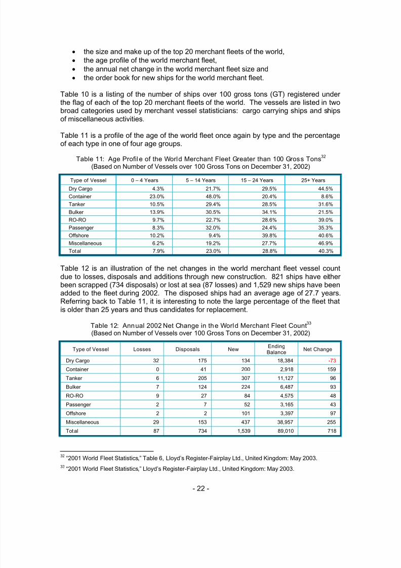
Table 10 is a listing of the number of ships over 100 gross tons (GT) registered underthe flag of each of the top 20 merchant fleets of the world. The vessels are listed in twobroad categories used by merchant vessel statisticians: cargo carrying ships and shipsof miscellaneous activities.
Table 11 is a profile of the age of the world fleet once again by type and the percentageof each type in one of four age groups.
Table 11: Age Profile of the World Merchant Fleet Greater than 100 Gross Tons32
(Based on Number of Vessels over 100 Gross Tons on December 31, 2002)
Type of Vessel 0 – 4 Years 5 – 14 Years 15 – 24 Years 25+ Years
Dry Cargo 4.3% 21.7% 29.5% 44.5%
Container 23.0% 48.0% 20.4% 8.6%Tanker 10.5% 29.4% 28.5% 31.6%
Bulker 13.9% 30.5% 34.1% 21.5%
RO-RO 9.7% 22.7% 28.6% 39.0%
Passenger 8.3% 32.0% 24.4% 35.3%
Offshore 10.2% 9.4% 39.8% 40.6%
Miscellaneous 6.2% 19.2% 27.7% 46.9%
Total 7.9% 23.0% 28.8% 40.3%
Table 12 is an illustration of the net changes in the world merchant fleet vessel countdue to losses, disposals and additions through new construction. 821 ships have eitherbeen scrapped (734 disposals) or lost at sea (87 losses) and 1,529 new ships have beenadded to the fleet during 2002. The disposed ships had an average age of 27.7 years.Referring back to Table 11, it is interesting to note the large percentage of the fleet thatis older than 25 years and thus candidates for replacement.
Table 12: Annual 2002 Net Change in the World Merchant Fleet Count33
(Based on Number of Vessels over 100 Gross Tons on December 31, 2002)
Type of Vessel Losses Disposals NewEndingBalance
Net Change
Dry Cargo 32 175 134 18,384 -73
Container 0 41 200 2,918 159
Tanker 6 205 307 11,127 96
Bulker 7 124 224 6,487 93
RO-RO 9 27 84 4,575 48Passenger 2 7 52 3,165 43
Offshore 2 2 101 3,397 97
Miscellaneous 29 153 437 38,957 255
Total 87 734 1,539 89,010 718
32“2001 World Fleet Statistics,” Table 6, Lloyd’s Register-Fairplay Ltd., United Kingdom: May 2003.
33“2001 World Fleet Statistics,” Lloyd’s Register-Fairplay Ltd., United Kingdom: May 2003.
5/9/2018 co2report2 - slidepdf.com
http://slidepdf.com/reader/full/co2report2 31/97
- 23 -
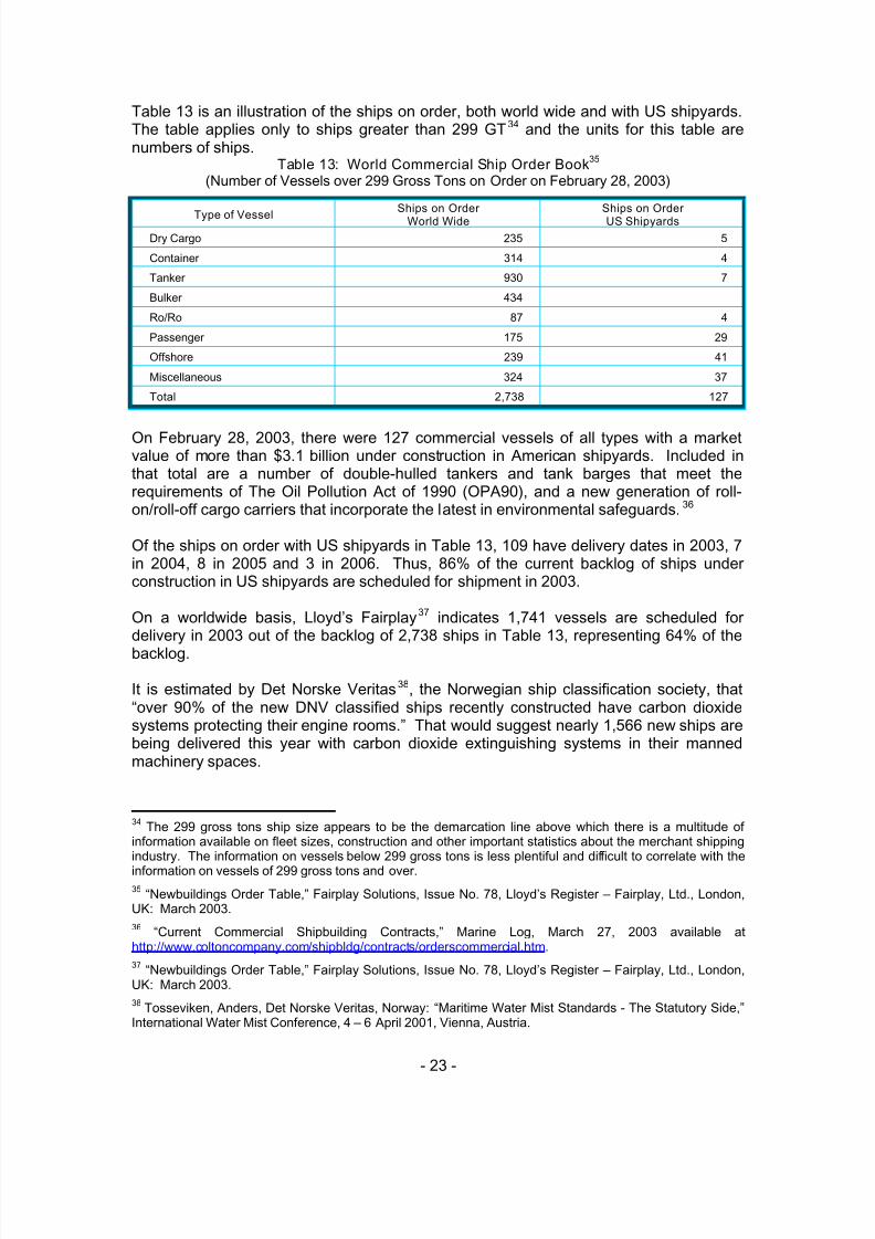
Table 13 is an illustration of the ships on order, both world wide and with US shipyards.The table applies only to ships greater than 299 GT34 and the units for this table arenumbers of ships.
Table 13: World Commercial Ship Order Book35
(Number of Vessels over 299 Gross Tons on Order on February 28, 2003)
Type of VesselShips on Order
World WideShips on OrderUS Shipyards
Dry Cargo 235 5
Container 314 4
Tanker 930 7
Bulker 434
Ro/Ro 87 4
Passenger 175 29
Offshore 239 41
Miscellaneous 324 37
Total 2,738 127
On February 28, 2003, there were 127 commercial vessels of all types with a marketvalue of more than $3.1 billion under construction in American shipyards. Included inthat total are a number of double-hulled tankers and tank barges that meet therequirements of The Oil Pollution Act of 1990 (OPA90), and a new generation of roll-on/roll-off cargo carriers that incorporate the latest in environmental safeguards.36
Of the ships on order with US shipyards in Table 13, 109 have delivery dates in 2003, 7in 2004, 8 in 2005 and 3 in 2006. Thus, 86% of the current backlog of ships underconstruction in US shipyards are scheduled for shipment in 2003.
On a worldwide basis, Lloyd’s Fairplay37 indicates 1,741 vessels are scheduled fordelivery in 2003 out of the backlog of 2,738 ships in Table 13, representing 64% of the
backlog.
It is estimated by Det Norske Veritas38, the Norwegian ship classification society, that“over 90% of the new DNV classified ships recently constructed have carbon dioxidesystems protecting their engine rooms.” That would suggest nearly 1,566 new ships arebeing delivered this year with carbon dioxide extinguishing systems in their mannedmachinery spaces.
34The 299 gross tons ship size appears to be the demarcation line above which there is a multitude of
information available on fleet sizes, construction and other important statistics about the merchant shippingindustry. The information on vessels below 299 gross tons is less plentiful and difficult to correlate with theinformation on vessels of 299 gross tons and over.
35“Newbuildings Order Table,” Fairplay Solutions , Issue No. 78, Lloyd’s Register – Fairplay, Ltd., London,
UK: March 2003.
36“Current Commercial Shipbuilding Contracts,” Marine Log, March 27, 2003 available at
http://www.coltoncompany.com/shipbldg/contracts/orderscommercial.htm.
37“Newbuildings Order Table,” Fairplay Solutions , Issue No. 78, Lloyd’s Register – Fairplay, Ltd., London,
UK: March 2003.
38Tosseviken, Anders, Det Norske Veritas, Norway: “Maritime Water Mist Standards - The Statutory Side,”
International Water Mist Conference, 4 – 6 April 2001, Vienna, Austria.

5/9/2018 co2report2 - slidepdf.com
http://slidepdf.com/reader/full/co2report2 32/97
- 24 -
8.1.2 United States Marine Market
a. Commercial Ships
Of the 127 commercial vessels under construction in US yards, 106 are being equippedwith carbon dioxide systems and 12 with FM-200 systems. The systems on the 9 othervessels could not be identified.
Table 14: Engine Room Protection on US Commercial Ships Under Construction39,40
Type of VesselNumber UnderConstruction
Carbon DioxideSystem
FM-200 System Unidentified
Dry Cargo 5 5
Container 4 4
Tanker 7 7
Bulker
Ro/Ro 4 4
Passenger 29 22 6 1
Offshore 41 41
Miscellaneous 37 23 6 8Total 127 106 12 9
It would appear from the information in Table 14 that the use of carbon dioxide systemsin new commercial ships being constructed in the US is in the vicinity of 8 out of 10,even though most of the commercial ships constructed in this country are consideredsmall to medium size. Some of the small and medium sized commercial vessels(passenger ferries, fire boats, etc.) are beginning to use FM-200 when the space andweight savings (when compared to carbon dioxide systems) are made apparent to thearchitect, engineers and owners.
b. Military Ships
Table 15 is an illustration of major military vessel projects now under construction.
The US military (both the US Navy and the US Army) have moved away from carbondioxide systems and are using FM-200 systems and/or water mist systems on their newships. While neither department has a written policy prohibiting the use of carbondioxide systems on new ships, the exclusion of carbon dioxide systems on new ships outof safety concerns has been the practice of each department for over 10 years.However, the US Coast Guard continues to employ carbon dioxide systems on buoytenders and coastal patrol boats that were designed before the approval of other halonalternatives.
After the last fatal accident involving a carbon dioxide system discharge on a US Navycombat ship (USS Sumter accident at Little Creek Amphibious Base on July 30, 1992)41
39“Current Commercial Shipbuilding Contracts,” Marine Log, March 27, 2003 available at
http://www.coltoncompany.com/shipbldg/contracts/orderscommercial.htm.
40The identification of the types of extinguishing systems employed on the list of ships in this table was
made through individual consultation with the marine sales managers of Ansul and Kidde-Fenwal, the twomajor manufacturers of fire extinguishing systems for marine applications.
41Three sailors were performing planned maintenance on a CO2 system in a paint locker when the system
discharged. Two died and one was seriously injured.

5/9/2018 co2report2 - slidepdf.com
http://slidepdf.com/reader/full/co2report2 33/97
- 25 -
the Navy took immediate remedial action to prevent similar accidents. They surveyedevery carbon dioxide system in the fleet and then developed and implemented acorrection plan involving three significant modifications to all systems in paint lockersand similar spaces that heretofore had not been equipped with time delays:
• time delays were installed on all systems together with pre-discharge alarms,
• protective caging was built around carbon dioxide cylinder control heads and• doors were modified to swing outward and provided with kick-out panels
In addition, the maintenance procedures were modified. Rescue parties -with allmembers equipped with self contained breathing apparatus - stand by outside the spacewhere maintenance on the carbon dioxide system is being performed and are ready toexecute an immediate rescue in the event of an accidental system discharge.
Table 15: Sampling of Major Military and USCG Vessel Projects42
Project Ships System
CVN-76 and CVN-77 Aircraft
Carriers 2 ships
FM-200 systems in lieu of halon systemsnormally fitted to aircraft carriers. In spaces
over 5,000 ft3 NRL WSCS43 system usedtogether with FM-200.
LPD-17 Class AmphibiousAssault Ships
12 shipsAll 5 machinery spaces employ water mistsystems; FM-200 to protect other spacesnormally protected with halon 1301.
T-AKE Military Sealift CommandAmmunition / Dry Cargo Ships
12 ships
FM-200 systems for machinery space protectionplus water spray and boundary protection formultipurpose spaces in lieu of carbon dioxidesystems
US Army Watercraft HalonRetrofit Project
60 vesselsRetrofit from halon 1301 to FM-200 systemstogether with NRL WSCS system.
US Army LSV (Army LogisticsSupport Vessels) Program
3 vesselsFM-200 systems to replace carbon dioxidesystems for machinery space protection
USCG WLB’s Oceangoing BuoyTenders 5 shipsCarbon dioxide systems (no approved cleanagent alternative systems available when shipswere designed)
USCG CPB Coastal Patrol Boats 13 ships Carbon dioxide systems
Both the US Navy and the Army still have ships equipped with carbon dioxide systems.
• In the Army’s case, it is actually removing the carbon dioxide systems from manyof its ships and replacing those systems with FM-200 together with a water spraycooling system in some cases.
• In the Navy, no new carbon dioxide systems have been installed in combatantships since the SUMTER accident over 10 years ago. The Navy is not replacingthe carbon dioxide systems on ships already equipped with those systems.
• In the U.S. Navy’s Military Sealift Command (MSC), many of its vessels usecarbon dioxide both for the protection of the cargo compartments and machineryspaces. However, with its latest ship series under construction, the T-AKE
42“Current Commercial Shipbuilding Contracts,” Marine Log, March 27, 2003 available at
http://www.coltoncompany.com/shipbldg/contracts/ordersgovernment.htm.
43The Water Spray Cooling System (WSCS), invented and patented by Naval Research Laboratory, was
designed to enhance the performance of gaseous total flooding fire suppression agents by providingcompartment cooling and reducing HF.

5/9/2018 co2report2 - slidepdf.com
http://slidepdf.com/reader/full/co2report2 34/97
- 26 -
ammunition / dry cargo ships (see Table 15) the MSC has chosen FM-200systems for the machinery spaces and is using overhead and bulkhead waterspray systems for the ammunition cargo spaces.
The MSC has had some unfortunate experiences with carbon dioxide including …..
•two incidents resulting in 2 fatalities each, the first on the CAPE DIAMOND in1993 and the second on the CAPE HORN in 2002 and …..
• a serious incident on another MSC ship, the SSG EDWARD A. CARTER, JR,which had a fire in its engine room while being loaded with (a net explosiveweight of) 5 million pounds of Class 1 explosives. The fire got out of control, thecrew was unable to operate the total flooding carbon dioxide system and the firehad to be extinguished by shore based and fire boat resources. There were 2fatalities, neither directly related to the carbon dioxide system. The USCGreport44 was critical of the configuration of the carbon dioxide system, the factthat it needed electrical power to open a discharge valve, the poor level of crewtraining and readiness and the actions of the ship’s officers.
However, the MSC is not using carbon dioxide on its newly constructed ships. With thenew T/AKE class under construction, the machinery spaces will be protected with ahalocarbon (FM-200) system designed to the requirements of IMO MSC Circular 848 45 together with a local application water system designed to the requirements of IMO MSCCircular 913.46
8.2 Industrial Market
The industrial market continues to be a large user of carbon dioxide systems. A surveyof manufacturers identified the five risks in Table 16 as the most frequently encounteredindustrial applications for carbon dioxide total flooding systems.
As shown in Table 16, most of the applications are in normally unoccupied spaces but,of those, most would also have people accessing the space for service, maintenance orother purposes.
In many of the applications, it is clear that other agents could do the job as well as, if notbetter than, carbon dioxide. For example, in the case of generator housings andenclosures, halocarbons and water mist systems are both available and, in the case ofwater mist, systems specifically approved for this application. Table 17 is an illustrationof the agents that could achieve the same technical level of performance as the carbondioxide systems for four of the five top applications. In this illustration, the responders tothe survey were asked to list their preferences for the top three alternatives to carbon
44 “Report of the Investigation into the Circumstances Surrounding the Engine Room Fire on Board the M/VSSG EDWARD A. CARTER, JR. While Moored at Military Ocean Terminal, Sunny Point, N.C., on July 14,2001 with the Loss of Two Lives,” Headquarters, United States Coast Guard, Washington, DC: September30, 2002 available at http://www.uscg.mil/hq/g-m/moa/casualty.htm
45"Revised Guidelines for the Approval of Equivalent Fixed Gas Fire-Extinguishing Systems, as Referred to
in SOLAS 74, for Machinery Spaces and Cargo Pump Rooms," Annex to IMO Maritime Safety CommitteeCircular 848, International Maritime Organization, 4 Albert Embankment, London SE1 7SR, England: June1998.
46“Guidelines for the Approval of Fixed Water-Based Local Application Fire-Fighting Systems for Use in
Category A Machinery Spaces,” MSC Circular 913, International Maritime Organization, London: May 1999.

5/9/2018 co2report2 - slidepdf.com
http://slidepdf.com/reader/full/co2report2 35/97
- 27 -
dioxide in the listed applications, thus resulting in the ranking of choices shown in Table17.
Table 16: Top Industrial Applications for Carbon Dioxide Total Flooding Systems
Application / RiskNormallyOccupied
NormallyUnoccupied
Accessible
Generator Housings / Enclosures Yes Yes
Flammable Liquid Storage (chemicals, paints, mixrooms)
Yes47
Yes Yes
Electrical Cabinets (controls, switchgear) Yes
Exhaust Systems (ducts / dust collectors / baghouses)
Yes
Misc. Mfg. Enclosures (ovens, vaults, pits, heattreating, etc)
Yes Yes
Table 17: Alternatives to Carbon Dioxide Total Flooding Systems
Application / Risk First ChoiceSecondChoice
ThirdChoice
Generator Housings / Enclosures Halocarbon Watermist Inert GasFlammable Liquid Storage (chemicals, paints, mixrooms)
Foam Inert Gas Halocarbon
Electrical Cabinets (controls, switchgear) Halocarbon Inert Gas Watermist
Exhaust Systems (ducts / dust collectors / baghouses)
N/A N/A N/A
Misc. Mfg. Enclosures (ovens, vaults, pits, heattreating, etc)
Inert GasDry
ChemicalWatermist
In that same survey, it was asked why would there be a preference for carbon dioxideover the alternatives. The following are the most often mentioned carbon dioxideattributes that – when taken collectively – serve as the basis for a bias toward carbondioxide systems in the industrial applications in Table 17:
• Cost (up-front investment, maintenance/service and recharge)• Best extinguishing media for risk or only practical agent
• Specialized design requirements (i.e. extended discharge, selector valves,piping/design flexibility and main/reserve)
• Clean agent (no damage, minimum cleanup, productivity downtime, non-corrosive, non-conductive, etc.)
• Deep seated fire capability
• Previous fire history
• Proven fire capability
• Globally available
• Insurance or authority having jurisdiction (AHJ) requirement (i.e. codecompliance, mandate, etc.)
It is clear that these attributes are not exclusive to carbon dioxide:
• Depending on the risk, any one of the alternatives could be declared the best
47Paint mix rooms are generally considered normally occupied spaces whereas most other flammable liquid
storage rooms are considered normally unoccupied.

5/9/2018 co2report2 - slidepdf.com
http://slidepdf.com/reader/full/co2report2 36/97
- 28 -
• Inert gases and halocarbons and to some extent water mist can be consideredclean agents
• Deep seated fires can be handled with water
• Previous fire history and proven fire capability are able to be demonstrated withthe other agents (perhaps not all the way back to 1929, though), and
• Global availability is certainly not a problem for inert gases and water.
However, the two attributes that are difficult for other agents to match when compared tocarbon dioxide systems are cost and AHJ preferences. Cost will be addressed later inthis report.
AHJ preferences are extremely difficult to overcome and are the single most significantreason for the long times experienced to bring a new product or technology tocommercial reality in the fire protection market. However, this is not altogether anegative attribute to ensure a very thorough review process when dealing in thebusiness of protecting lives and property.
Finally, in the survey the respondents were asked to identify any applications where theyfelt carbon dioxide total flooding systems are the only appropriate solution. Thefollowing five applications were identified:
• Large industrial pits
• Industrial ovens
• Machining centers / equipment
• Electrical transformers
• Class “A” deep seated fire hazards (wherever water is unsuitable)
**********

5/9/2018 co2report2 - slidepdf.com
http://slidepdf.com/reader/full/co2report2 37/97
- 29 -
9 Standards and Regulations
Nationally and internationally there are several organizations that provide guidance onthe safe application of carbon dioxide systems. These include:
• U.S. Environmental Protection Agency (EPA)
• U.S. Coast Guard (USCG)
• National Fire Protection Association (NFPA)
• Occupational Safety and Health Administration (OSHA)
• International Standards Organization (ISO)
• International Maritime Organization (IMO)
At this time, the regulations or standards of all of these organizations permit the use ofcarbon dioxide total flooding fire extinguishing systems in normally occupied spaces.Some of the standards and regulations of the above organizations are linked to others,either by direct reference or by the simple fact that the same people are working on therequirements in several different organizations. For example ….
• consistent with federal policy, the USCG is trying, when appropriate, to usereferences to NFPA consensus standards as its requirements for marine fireextinguishing systems, …..
• NFPA 2001 directly references the US EPA SNAP list as an acceptancerequirement for agents to be included in that standard, …..
• IMO has begun the practice of adopting by reference some ISO documentswhenever there seems to be a close fit, …..
• the US EPA directly references OSHA and NFPA standards in its SNAP list, …..
• USCG personnel, together with many US members of the NFPA technical
committees and EPA personnel constitute the US delegation to the IMO fireprotection sub-committee and …..
• many members of NFPA technical committees form the US delegations to ISOtechnical committees for fire extinguishing systems.
9.1 U.S. Environmental Protection Agency
Under Title VI of the Clean Air Act (CAA)48, EPA's Global Programs Division isresponsible for several programs that protect the stratospheric ozone layer.
Under Section 612 of the Clean Air Act, EPA has been charged with developing aprogram for evaluating alternatives to ozone-depleting substances. EPA refers to this as
the Significant New Alternatives Policy (SNAP) program. The major provisions ofsection 612 that direct the EPA to assess human health and environmental impacts ofthe halon alternatives are:
• Rulemaking - Section 612(c) requires EPA to promulgate rules making it unlawfulto replace any class I or class II substance with any substitute that theAdministrator determines may present adverse effects to human health or theenvironment where the Administrator has identified an alternative that (1)
48The provisions of the Clean Air Act can be accessed at http://www.epa.gov/oar/caa/contents.html

5/9/2018 co2report2 - slidepdf.com
http://slidepdf.com/reader/full/co2report2 38/97
- 30 -
reduces the overall risk to human health and the environment, and (2) is currentlyor potentially available.
• Listing of Unacceptable/Acceptable Substitutes - Section 612(c) also requiresEPA to publish a list of the substitutes unacceptable for specific uses. EPA mustpublish a corresponding list of acceptable alternatives for specific uses.
• Updates/Changes to Determinations - Section 612 also authorizes EPA to initiatechanges to the SNAP determinations independent of any petitions or notificationsreceived. These amendments can be based on new data on either additionalsubstitutes or on characteristics of substitutes previously reviewed.
Substitutes are reviewed on the basis of ozone depletion potential, global warmingpotential, toxicity, flammability and exposure potential. EPA describes its approach toreviewing substitutes for ozone-depleting substances in the SNAP Final Rule49. TheSNAP lists of acceptable and unacceptable substitutes are updated several times eachyear. The current version of the SNAP list covering total flooding extinguishing agentsystems50 addresses the use of total flooding carbon dioxide systems. In 1994, EPAlisted carbon dioxide systems as acceptable under SNAP but did not conduct a risk
assessment. EPA, in its listing, deferred to OSHA which had already promulgatedregulations for use of carbon dioxide total flooding fire suppression systems. At thistime, the SNAP list identifies carbon dioxide as an acceptable substitute for halon 1301with the comment that the “System design must adhere to OSHA 1910.162(b)(5)51 andNFPA Standard 12.”52 The full text of the referenced OSHA paragraph is …..
1910.162(b)(5) The employer shall provide a distinctive pre-discharge employeealarm capable of being perceived above ambient light or noise levels when agentdesign concentrations exceed the maximum safe level for employee exposure. Apre-discharge employee alarm for alerting employees before system dischargeshall be provided on Halon 1211 and carbon dioxide systems with a designconcentration of 4 percent or greater and for Halon 1301 systems with a design
concentration of 10 percent or greater. The pre-discharge employee alarm shallprovide employees time to safely exit the discharge area prior to systemdischarge.
The requirements of NFPA Standard 12 are discussed in paragraph 9.3.
9.2 U.S. Coast Guard
The United States Coast Guard regulations address two subjects: (1) where carbondioxide systems (or their equivalents) are required and (2) how those systems should bedesigned and installed.
49“Final Rule - Protection of Stratospheric Ozone,” 40 CFR Parts 9 and 82, [FRL-4839-7], RIN 2060-AD48,
Vol. 59 No. 53 Friday, March 18, 1994 p 13044 (Rule), Environmental Protection Agency (EPA),Washington, DC available at http://www.epa.gov/ozone/snap/regs/59fr13044.html
50“Substitutes for Halon 1301 as a Total Flooding Agent,” Significant New Alternatives Policy (SNAP)
Program, Environmental Protection Agency (EPA), Washington, DC available athttp://www.epa.gov/ozone/snap/fire/lists/flood.html
51“Fixed Extinguishing Systems, Gaseous Agent,” 29 CFR 1910, Occupational Safety and Health
Standards, Subpart L, Fire Protection, Standard Number 1910.162, Occupational Safety and HealthAdministration, Washington, DC available at http://www.osha.gov/comp-links.html
52“NFPA 12 - Standard on Carbon Dioxide Extinguishing Systems,” National Fire Protection Association,
Quincy, MA: February 2000.

5/9/2018 co2report2 - slidepdf.com
http://slidepdf.com/reader/full/co2report2 39/97
- 31 -
The USCG regulations are contained in Title 46 – Shipping of the Code of FederalRegulations. The regulations for carbon dioxide systems are contained in severaldifferent sub-chapters of Title 46 organized along the lines of the several classes ofships and vessels covered. Table 18 is an illustration of the relevant documentsdescribing the requirements of carbon dioxide systems for several of the more important
vessel types.
The requirements from one class of vessel to another do not vary significantly, exceptthat the treatment of carbon dioxide systems in Sub-Chapters D, H and I is quite dated,even to the extent of discussing special exemptions for ships built before 1952. Thetreatment of carbon dioxide systems and the equivalents in Sub-Chapters K and T are,relatively speaking, more recent and probably reflect the current thinking of the USCGwith respect to gaseous extinguishing system requirements for all the different types ofvessels.
Table 18: USCG Regulations for Carbon Dioxide Fire Extinguishing Systems53
Sub-Chapter Topic Sub-Part Title Paragraph
C Uninspected VesselsPart 25
Subpart 25.30
Fire ExtinguishingEquipment
§ 25.30-15
C Commercial Fishing VesselsPart 28
Subpart D
Fixed Gas FireExtinguishingSystems
§ 28.320
D Tank VesselsPart 34
Subpart 34.15
Carbon DioxideExtinguishingSystems
§ 34.15-1
HPassenger Vessels
(>100 gross tons)
Part 76
Subpart 76.15
Carbon DioxideExtinguishingSystems
§ 76.15-1
I Cargo VesselsPart 95
Subpart 95.15
Carbon DioxideExtinguishing
Systems
§ 95.15-1
I-A Mobile Offshore Drilling UnitsPart 108
Subpart D
Carbon DioxideSystems
§ 108.431
K
Passenger Vessels
(<100 gross tons)
(>150 passengers)
Part 118
Subpart D
Fixed FireExtinguishing andDetecting Systems
§ 118.400
L Offshore Supply VesselsPart 132
Subpart CMiscellaneous § 132.310
R Public Nautical School ShipsPart 167
Subpart 167.45
Steam, carbondioxide, and halonfire extinguishingsystems
§ 167.45-1
RCivilian Nautical SchoolVessels
Part 169
Subpart 169.50
Fixed extinguishingsystem
§ 169.564
TSmall Passenger Vessels(<100 gross tons)
(<150 passengers)
Part 181
Subpart D
Fixed FireExtinguishing andDetecting Systems
§ 181.400
UOceanographic ResearchVessels
Part 193
Subpart 193.15
Carbon DioxideExtinguishingSystems
§ 193.15-1
53The referenced USCG regulations are available at http://www.uscg.mil/hq/g-m/MSE4/reg.htm
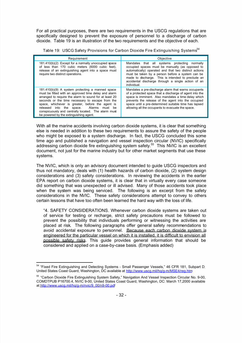
5/9/2018 co2report2 - slidepdf.com
http://slidepdf.com/reader/full/co2report2 40/97
- 32 -
For all practical purposes, there are two requirements in the USCG regulations that arespecifically designed to prevent the exposure of personnel to a discharge of carbondioxide. Table 19 is an illustration of the two requirements and the objective of each.
Table 19: USCG Safety Provisions for Carbon Dioxide Fire Extinguishing Systems54
Requirement Objective181.410(b)(2) Except for a normally unoccupied spaceof less than 170 cubic meters (6000 cubic feet),release of an extinguishing agent into a space mustrequire two distinct operations.
Mandates that all systems protecting normallyoccupied spaces must be manually (as opposed toautomatically) operated and that two distinct actionsmust be taken by a person before a system can bemade to discharge. This is intended to preclude anaccidental discharge through a single action of anindividual.
181.410(b)(9) A system protecting a manned spacemust be fitted with an approved time delay and alarmarranged to require the alarm to sound for at least 20seconds or the time necessary to escape from thespace, whichever is greater, before the agent isreleased into the space. Alarms must beconspicuously and centrally located. The alarm mustbe powered by the extinguishing agent.
Mandates a pre-discharge alarm that warns occupantsof a protected space that a discharge of agent into thespace is imminent. Also mandates a time delay whichprevents the release of the agent into the occupiedspace until a pre-determined suitable time has lapsedallowing all the occupants to evacuate the space.
With all the marine accidents involving carbon dioxide systems, it is clear that somethingelse is needed in addition to these two requirements to assure the safety of the peoplewho might be exposed to a system discharge. In fact, the USCG concluded this sometime ago and published a navigation and vessel inspection circular (NVIC) specificallyaddressing carbon dioxide fire extinguishing system safety.55 This NVIC is an excellentdocument, not just for the marine industry but for other market segments that use thesesystems.
The NVIC, which is only an advisory document intended to guide USCG inspectors andthus not mandatory, deals with (1) health hazards of carbon dioxide, (2) system designconsiderations and (3) safety considerations. In reviewing the accidents in the earlier
EPA report on carbon dioxide systems, it is clear that in virtually every case someonedid something that was unexpected or ill advised. Many of those accidents took placewhen the system was being serviced. The following is an excerpt from the safetyconsiderations in the NVIC. These safety considerations attempt to convey to otherscertain lessons that have too often been learned the hard way with the loss of life.
“4. SAFETY CONSIDERATIONS. Whenever carbon dioxide systems are taken outof service for testing or recharge, strict safety precautions must be followed toprevent the possibility that individuals performing or witnessing the activities areplaced at risk. The following paragraphs offer general safety recommendations toavoid accidental exposure to personnel. Because each carbon dioxide system isengineered for the particular vessel on which it is installed, it is difficult to envision all
possible safety risks. This guide provides general information that should beconsidered and applied on a case-by-case basis. (Emphasis added )
54“Fixed Fire Extinguishing and Detecting Systems - Small Passenger Vessels,” 46 CFR 181, Subpart D,
United States Coast Guard, Washington, DC available at http://www.uscg.mil/hq/g-m/MSE4/reg.htm
55 “Carbon Dioxide Fire Extinguishing System Safety,” Navigation And Vessel Inspection Circular No. 9-00,COMDTPUB P16700.4, NVIC 9-00, United States Coast Guard, Washington, DC: March 17,2000 availableat http://www.uscg.mil/hq/g-m/nvic/9_00/n9-00.pdf
5/9/2018 co2report2 - slidepdf.com
http://slidepdf.com/reader/full/co2report2 41/97
- 33 -
• Most accidents related to the testing or recharge of installed carbon dioxidesystems are attributable to personnel errors. It is therefore critical that allpersons working on the system must be fully knowledgeable in its operationand repair.
• If the system protects multiple spaces, be aware of the possibility of split
discharges.• All personnel must be evacuated from the protected spaces while any
service, however minimal, is performed.
• Establish and implement a plan to prevent personnel entry into the protectedspaces until testing is completed and the spaces have been ventilated anddetermined to be safe for human occupancy.
• Before beginning, determine that a means of communication is available tosummon help if it is needed. Confirm that the means of communication isoperable and effective throughout the areas where personnel will bestationed.
• Provide ready access to self-contained breathing apparatus.• Determine what shipboard equipment will be disabled or operated if the
system discharges.
• Before beginning, evaluate the location of the agent storage room and planan escape route.
• The overall condition of the system should be evaluated before beginning anywork.
• Protect exposed high pressure cylinder valves.
• Disconnect all high-pressure cylinders from the manifold if the systemdistribution piping is to be pressure tested, or if an actuation test will beperformed.
• On low-pressure systems, verify that the tank shutoff valve is closed duringtesting.
• Verify that all control heads are correctly re-installed after the work iscompleted.
• Verify that all stop valve or selector valve remote release controls areconnected to the proper valves.
• If an accidental release occurs, immediately evacuate and do not re-enter thespaces affected until they have been ventilated and tested for an adequate
oxygen concentration.”
9.3 National Fire Protection Association
The National Fire Protection Association develops, publishes, and disseminatesconsensus codes and standards intended to minimize the possibility and effects of fireand other risks. Virtually every building, process, service, design, and installation insociety today is affected by NFPA documents. More than 300 NFPA codes andstandards are used around the world.

5/9/2018 co2report2 - slidepdf.com
http://slidepdf.com/reader/full/co2report2 42/97
- 34 -
Among these, there are two standards dealing with gaseous extinguishing agentsystems that approach the matter of personnel safety quite differently. These are …..
• NFPA 12 Standard on Carbon Dioxide Extinguishing Systems56
• NFPA 2001 Standard on Clean Agent Fire Extinguishing Systems57
9.3.1 NFPA 12NFPA Standard 12 was first published in 1929 and has been updated a total of 25 timessince that first version. Today, the standard lists the following as its scope and purpose:
1-1* Scope. This standard contains minimum requirements for carbondioxide fire extinguishing systems. It includes only the necessaryessentials to make the standard workable in the hands of those skilled inthis field. (Emphasis added )
1-2 Purpose.
1-2.1 This standard is prepared for the use and guidance of thosecharged with the purchasing, designing, installing, testing, inspecting,
approving, listing, operating, or maintaining of carbon dioxide fireextinguishing systems, in order that such equipment will function asintended throughout its life. Nothing in this standard is intended to restrictnew technologies or alternate arrangements, provided the level of safetyprescribed by the standard is not lowered.
1-2.2 Only those with the proper training and experience shall design,install, inspect, and maintain this equipment.
Appendix C is an excerpt of the requirements and related explanatory material regardinghazards to personnel and system requirements. These include …..
• A discussion of hazards to personnel including suffocation, reduced visibility
during and after the discharge period, the migration of carbon dioxide intoadjacent places outside of the protected space, the fact that personnel could betrapped in or enter into an atmosphere made hazardous by a carbon dioxidedischarge and the need to ensure prompt evacuation and rescue of trappedpersonnel.
• The standard goes to great lengths to describe the placement of warning signs ...
o in every protected space
o at every entrance to protected space
o in every nearby space where carbon dioxide can accumulate to hazardouslevels
o outside each entrance to carbon dioxide storage roomso at every location where manual operation of the system can occur.
• The standard describes system design requiring the provision of audible andvisual predischarge alarms and time delays of sufficient duration to allow for
56“NFPA 12 - Standard on Carbon Dioxide Extinguishing Systems – 2000 Edition,” National Fire Protection
Association, Quincy, MA: February 2000.
57“NFPA 2001 - Standard on Clean Agent Fire Extinguishing Systems - 2000 Edition," National Fire
Protection Association, Quincy, MA: February 2000.

5/9/2018 co2report2 - slidepdf.com
http://slidepdf.com/reader/full/co2report2 43/97
- 35 -
evacuation under worst-case conditions. However, it also permits the time delayto be bypassed under certain circumstances.
• A new requirement in the 2000 version of the standard is the provision of a“lockout” mechanism when persons not familiar with the systems and theiroperation are present in a protected space. Examples of situations that could
require lock-out of a total flooding system are when persons are so locatedwhere they cannot easily exit the protected space within the system’s time delayperiod. The requirements of the lockout are very specific and do not includeelectrical or electronic switching to accomplish this:
1-3.7 Lock-Out. A manually operated valve in the discharge pipebetween the nozzles and the supply, which can be locked in the closedposition to prevent flow of carbon dioxide to the protected area.
• Personnel training is required to include all persons that can at any time enter aspace protected by carbon dioxide, warning them of the hazards involved, givenan alarm signal and provided with safe evacuation procedures. The trainingrequires making people aware that the discharge of carbon dioxide can cause
eye injury, ear injury, or even falls due to loss of balance upon the impingementof the high velocity discharging gas.
9.3.2 NFPA 2001
NFPA 2001 covers systems using clean alternatives to halons, principally halocarbonand inert gas agents at this time. NFPA 2001 was first published in 1994 and has beenupdated twice since that first version. Of the two NFPA standards (12 and 2001), NFPA2001 has clearly had more effort put into addressing system safety. Today, the standardlists the following as its scope and purpose:
1-1 Scope. This standard contains minimum requirements for totalflooding clean agent fire extinguishing systems. It does not cover fire
extinguishing systems that use carbon dioxide or water as the primaryextinguishing media, which are addressed by other NFPA documents.
1-2 Purpose.
1-2.1 The agents in this standard were introduced in response tointernational restrictions on the production of certain halon fireextinguishing agents under the Montreal Protocol signed September 16,1987, as amended. This standard is prepared for the use and guidanceof those charged with purchasing, designing, installing, testing,inspecting, approving, listing, operating, and maintaining engineered orpre-engineered clean agent extinguishing systems, so that suchequipment will function as intended throughout its life. Nothing in this
standard is intended to restrict new technologies or alternatearrangements provided the level of safety prescribed by this standard isnot lowered.
1-2.2 No standard can be promulgated that will provide all the necessarycriteria for the implementation of a total flooding clean agent fireextinguishing system. Technology in this area is under constantdevelopment, and this will be reflected in revisions to this standard. Theuser of this standard must recognize the complexity of clean agent fireextinguishing systems. Therefore, the designer is cautioned that thestandard is not a design handbook. The standard does not do away with

5/9/2018 co2report2 - slidepdf.com
http://slidepdf.com/reader/full/co2report2 44/97
- 36 -
the need for the engineer or for competent engineering judgment. It isintended that a designer capable of applying a more complete andrigorous analysis to special or unusual problems shall have latitude in thedevelopment of such designs. In such cases, the designer is responsiblefor demonstrating the validity of the approach. or uninsulated liveelectrical components not at ground potential.
Appendix D is an excerpt of the requirements and related explanatory material regardinghazards to personnel redischarge alarms, time delays and maximum safe exposurelimits. From the safety standpoint, NFPA 2001 differs from NFPA 12 in three fairlysignificant ways.
• No agent can be included in the NFPA 2001 standard until it has been throughan environmental and safety review in a manner equivalent to the process usedby the U.S. Environmental Protection Agency’s (EPA) SNAP Program.
1-6.1* Hazards to Personnel.
1-6.1.1* Any agent that is to be recognized by this standard or proposed
for inclusion in this standard shall first be evaluated in a mannerequivalent to the process used by the U.S. Environmental ProtectionAgency’s (EPA) SNAP Program.
• NFPA 2001 requires a predischarge alarm and a time delay on all systems (withone exception), even on systems where the agent is used at concentrations wellbelow levels approaching a safety concern.
2-3.5.6 Time Delays.
2-3.5.6.1* For clean agent extinguishing systems, a pre-discharge alarmand time delay, sufficient to allow personnel evacuation prior todischarge, shall be provided. For hazard areas subject to fast growthfires, where the provision of a time delay would seriously increase the
threat to life and property, a time delay shall be permitted to beeliminated.
2-3.5.6.2 Time delays shall be used only for personnel evacuation or toprepare the hazard area for discharge.
2-3.5.6.3 Time delays shall not be used as a means of confirmingoperation of a detection device before automatic actuation occurs.
• Similarly, NFPA 2001 displays a healthy skepticism about the reliability ofpredischarge alarms and time delays by mandating that agents be used atconcentrations below their demonstrated safe exposure limits in the event thepredischarge alarm and/or time delays fail to operate properly. First, therequirements for halocarbon agents …..
1-6.1.2* Halocarbon Agents.
1-6.1.2.1 Any unnecessary exposure to halocarbon clean agents, even atNOAEL concentrations, and halocarbon decomposition products shall beavoided. The requirement for pre-discharge alarms and time delays areintended to prevent human exposure to agents. The following additionalprovisions shall apply in order to account for failure of these safeguards:…..
….. and then the requirements for inert gas systems …..

5/9/2018 co2report2 - slidepdf.com
http://slidepdf.com/reader/full/co2report2 45/97
- 37 -
1-6.1.3* Inert Gas Clean Agents. Unnecessary exposure to inert gasagent systems resulting in low oxygen atmospheres shall be avoided.The requirement for pre-discharge alarms and time delays is intended toprevent human exposure to agents. The following additional provisionsshall apply in order to account for failure of these safeguards: …..
….. where both then go on to describe the maximum safe exposure limits for thevarious halocarbons and inert gases (see Appendix D).
9.4 Occupational Safety and Health Administration
An excerpt from the OSHA regulations describing the general requirements for fixedextinguishing systems (29 CFR 1910.160) together with the specific requirements forgaseous extinguishing systems (29 CFR 1910.162) are at Appendix E.
The general requirements include the employer’s responsibility to
• provide effective safeguards to warn employees against entry into dischargeareas;
• post hazard warning or caution signs;
• assure that fixed systems are inspected annually;
• assure that the weight and pressure of refillable containers is checked at leastsemi-annually;
• provide an emergency action plan;
• provide a pre-discharge alarm and time delay;
The specific requirements for fixed gaseous systems include the employer’sresponsibility to
• assure that the concentration of gaseous agents is maintained;
• assure that employees are not exposed;
• assure that no unprotected employees enter the area during agent discharge.
9.5 International Standards Organization
ISO Standard 618358 for carbon dioxide fire extinguishing systems was first published in1990 and has not been revised since. The following as its scope:
Scope
This International Standard lays down requirements for the design andinstallation of fixed carbon dioxide fire-extinguishing systems for use onpremises. The requirements are not valid for extinguishing systems onships, in aircraft, on vehicles and mobile fire appliances or for belowground systems in the mining industry, nor are they valid for carbondioxide pre-inerting systems.
58“Fire Protection Equipment - Carbon Dioxide Extinguishing Systems for Use on Premises - Design and
Installation,” International Standard ISO 6183 : 1990 (E), International Standards Organization, First edition,July 1990.

5/9/2018 co2report2 - slidepdf.com
http://slidepdf.com/reader/full/co2report2 46/97
- 38 -
Appendix F is an excerpt of the requirements and related explanatory material regardingsafety requirements, including ….
• exit routes
• warning and instruction and direction signs
• alarms
• outward swinging self-closing doors
• self-contained breathing equipment
• personnel training
• ventilation of the areas after extinguishing the fire
The standard has specific requirements for …..
• precautions for Iow-lying parts of protected areas.
• precautions during maintenance work.
9.6 International Maritime Organization
The requirements for carbon dioxide systems that are employed on ships oninternational voyages fall under the regulations promulgated under the InternationalConvention for the Safety of Life at Sea, 1974, an international ship safety treaty, alsoreferred to as SOLAS. Those requirements are detailed in the Fire Systems SafetyCode (FSS Code)59 which has the following stated purpose:
“The purpose of this Code is to provide international standards of specificengineering specifications for fire safety systems required by chapter II-2of the International Convention for the Safety of Life at Sea, 1974, asamended.”
An excerpt from this Code pertaining to the safety requirements for carbon dioxide
systems is shown at Appendix G. In general, though, the requirements are rathersimple, covering the following:
• A requirement to prevent inadvertent release of the agent into the space togetherwith guidelines about routing piping for the systems through accommodations orpassenger spaces.
• A requirement for a predischarge alarm and time delay of at least 20 seconds topermit personnel evacuation from “ro-ro spaces and other spaces in whichpersonnel normally work or to which they have access.” Conventional cargospaces and “small spaces” are exempted from these requirements.
• A requirement that the controls for of any fixed gas fire-extinguishing systemhave clear instructions relating to the operation of the system having regard tothe safety of personnel.
• The requirement that all systems must be manually operated. That is, automaticrelease of the fire-extinguishing system is not permitted.
• Plus the requirement that carbon dioxide systems must have two separatecontrols, one control for opening the valve of the piping which conveys the gas
59 “International Code for Fire Safety Systems, Chapter 5, Fixed Gas Fire Extinguishing Systems,”International Maritime Organization, 4 Albert Embankment, London SE1 7SR, England: July 2002.

5/9/2018 co2report2 - slidepdf.com
http://slidepdf.com/reader/full/co2report2 47/97
- 39 -
into the protected space and a second control for opening the valve on the agentstorage containers.
Concern over the use of carbon dioxide systems has been expressed at the 47 th meetingof the IMO Fire Protection Sub-Committee in February 2003 where three documentswere submitted on this subject.
• First, a report60 by the Correspondence Group on Performance Testing andApproval Standards for Fire Safety Systems that described specific tasks for aworking group to accomplish. The following is a verbatim excerpt from thatreport and attention is called to point .9:
“.4 Fixed gas fire-extinguishing systemsConsider revising MSC/Circ.848 for fixed gas fire-extinguishing systems,including inert gases required by regulation II-2/10.4.1.1.1 and 10.9.1.1to:.1 add the PBPK model for toxicity;.2 add component manufacturing standards;.3 define a standard cup burner test;
.4 identify necessary changes for testing of inert gases;
.5 decide on the need for a minimum vent opening;
.6 harmonize the minimum fire size with MSC/Circ. 668;
.7 correlate the volume of the test enclosure with the actual engineroom volume;
.8 decide if a fire exposure test should be required for agent storagecontainers and control system components located inside theprotected space; and
.9 decide if carbon dioxide should be prohibited in occupied spaces.”
• Second, a paper61 submitted by Denmark, called for changes to the requirementsfor carbon dioxide systems to improve their safety performance. The Danish
proposal included this statement:“4 It should also be noted that CO2 systems are still being released byaccident so the safety of the personnel in the concerned spaces shouldhave high priority in the Sub-Committee’s consideration of this matter. “
• Third, a paper62 submitted by the United States transmitting for the information ofIMO delegations a copy of the Merchant Shipping Case Study excerpt from the2002 Assessment Report63 of the UNEP Halons Technical Options Committee.The following excerpt addresses the use of carbon dioxide systems in shipboardmachinery spaces:
60
“Report of the Correspondence Group on Performance Testing and Approval Standards for SafetySystems,” Document FP 47/8, International Maritime Organization, 4 Albert Embankment, London SE1 7SR,England: November 2002.
61“Proposal for Amending the International Code for Fire Safety Systems,” Document FP 47/8/1, Submitted
by Denmark, International Maritime Organization, 4 Albert Embankment, London SE1 7SR, England:November 2002.
62“Availability of Halons Used on Board Ships,” Document FP 47/INF.5, Submitted by the United States,
International Maritime Organization, 4 Albert Embankment, London SE1 7SR, England: November 2002.
63“2002 Assessment Report of the Halons Technical Options Committee,” ISBN 92-807-2286-7, Ozone
Secretariat, United Nations Environment Program, Nairobi, Kenya: March 2003.

5/9/2018 co2report2 - slidepdf.com
http://slidepdf.com/reader/full/co2report2 48/97
- 40 -
“But a recent survey has illustrated that 9 out of 10 new ships use carbondioxide systems for the protection of the machinery space. Whilesystems using the new halon alternatives are safer than carbon dioxide interms of personnel exposure to the agents, they are all more expensivethan carbon dioxide systems, thus accounting for the new popularity ofcarbon dioxide. Irrespective of the safety devices and measures
employed with total flooding carbon dioxide systems, the history of deathsand injuries caused by these systems is ample evidence that theirwholesale employment will likely produce higher rates of deaths andinjuries than we are currently experiencing. This regression to carbondioxide systems has alarmed many health and safety officials. On thebasis of the growing life safety concerns, it is likely there will be efforts toeffect a ban on the use of carbon dioxide total flooding systems innormally occupied spaces, including shipboard machinery spaces.”
**********

5/9/2018 co2report2 - slidepdf.com
http://slidepdf.com/reader/full/co2report2 49/97
- 41 -
10 Alternatives
Many feel that the increased usage of carbon dioxide total flooding systems, especiallyin the marine market, is the direct result of our inability to produce a cost effectivealternative to halon 1301. From 1987 and nearly up until the halt of production of new
halon extinguishing agents in the United States in January 1994, the fire protectionindustry was generally optimistic that the development of alternatives to halons wouldproduce an improved new line of replacement agents. However, it became apparentthat some compromises were necessary in order to accept the alternatives to halons thatwere ultimately developed. Table 20 is an illustration of some of the agentcharacteristics the industry felt were important, the level expected and what was actuallyachieved.
Table 20: Alternatives to Halons - Expectations versus Reality
Characteristic Expectations Reality
Extinguishing Effectiveness More effective than halons Less effective than halons
Cost Less expensive than halons More expensive than halons
Environmental Impact Zero ozone depletion potential Achieved
Safety Safer than halons Achieved
Had all the expectations in Table 20 been achieved, many believe that carbon dioxidetotal flooding systems would be a thing of the past. Unfortunately, by failing to achieveall the expectations, especially the matter of cost, the employment of carbon dioxidesystems has proliferated.
10.1 General
From a technical standpoint, there are several types of systems that can performcomparably if not better than carbon dioxide in total flooding applications:
• Halocarbon gaseous extinguishing systems
• Inert gas extinguishing systems
• Water mist extinguishing systems
In addition, under certain circumstances, there are additional alternative systems thatmight be appropriate, including:
• Aerosol extinguishing systems
• Preaction water sprinkler systems
•Ordinary water sprinkler systems
• Low, medium and high expansion foam systems
• Dry chemical systems
In the marine market, IMO has developed guidelines for the approval of systemsconsidered equivalent to carbon dioxide systems for the protection of machinery spaces.

5/9/2018 co2report2 - slidepdf.com
http://slidepdf.com/reader/full/co2report2 50/97
- 42 -
Three separate guidelines deal with water mist,64 halocarbon or inert gas65 and aerosolsystems.66
The US EPA funded an earlier report67 addressing the development and marketacceptance of several alternatives to halons. The information in that report dealt withthe long path to commercialization, the status of various agents along that path, a
comparison of environmental properties of the agents and a quick look at some of therelative costs.
From a total flooding system standpoint, that report concluded that there has beencommercial acceptance of two types of agents …..
• gaseous agents including halocarbons and inert gas agents and …..
• water mist extinguishing systems …..
….. and that while aerosol extinguishing systems present some potential, thosetypes of agents have not yet achieved any significant level of acceptance, especially inthe US.
10.2 Gaseous Extinguishing Agents for Fixed Systems From the gaseous extinguishing agents standpoint, the report also pointed out that someof the agents that had been incorporated into national and international standards68,69 never really achieved commercial success and others are already on a phase-outschedule (e.g. the HCFC’s). Thus many of those agents are probably beyondconsideration as suitable alternatives to halons, carbon dioxide or anything else. In theend, the agents in Table 21 can be considered viable gaseous alternatives to competewith carbon dioxide in many applications. While accepted for the next editions but notyet included in the current cited standards, a new halocarbon agent, identified as FK-5-1-12, or 3M Novec 1230 Fire Protection Fluid, has been listed as acceptable by EPA’sSNAP program,70 so it too is included in Table 21.
64“Amendments to the Test Method for Equivalent Water-Based Fire-Extinguishing Systems for Machinery
Spaces of Category A and Cargo Pumprooms Contained in MSC Circular 668, Annex, Appendix B,”International Maritime Organization, 4 Albert Embankment, London SE1 7SR, England: June 1996.
65"Revised Guidelines for the Approval of Equivalent Fixed Gas Fire-Extinguishing Systems, as Referred to
in SOLAS 74, for Machinery Spaces and Cargo Pump Rooms," Annex to IMO Maritime Safety CommitteeCircular 848, International Maritime Organization, 4 Albert Embankment, London SE1 7SR, England: June1998.
66“Guidelines for the Approval of Fixed Aerosol Fire-Extinguishing Systems Equivalent to Fixed Gas Fire-
Extinguishing Systems, as Referred to in SOLAS 74, for Machinery Spaces;” MSC/Circ.1007, InternationalMaritime Organization, London: June 2001.
67
Wickham, Robert. T, “Status Of Industry Efforts To Replace Halon Fire Extinguishing Agents,” WickhamAssociates, Stratham, NH: March 2002 available at http://www.epa.gov/ozone/snap/index.html
68"NFPA 2001 - Standard on Clean Agent Fire Extinguishing Systems - 2000 Edition," National Fire
Protection Association, Quincy, MA: February 2000.
69"International Standard on Gaseous Fire-Extinguishing Systems," ISO 14520-1 through 14520-15,
available from Standards Association of Australia, GPO Box 5420, Sydney, NSW 2001, Australia: August2000.
70“Protection of Stratospheric Ozone: Notice 17 for Significant New Alternatives Policy Program,” 40 CFR
Part 82, Environmental Protection Agency, [FRL–7425–6], Federal Register / Vol. 67, No. 245 / 77927,Friday, December 20, 2002.

5/9/2018 co2report2 - slidepdf.com
http://slidepdf.com/reader/full/co2report2 51/97
- 43 -
Table 21: Gaseous Alternatives to Carbon Dioxide for Total Flooding Systems
Generic Name Trade Name Group Chemical Composition
HFC-23 FE-13 HFC CHF3
HFC-125 FE-25 HFC CF3CHF2
HFC-227ea FM-200 HFC CF3CHFCF3
FK-5-1-12 Novec 1230 FK CF3CF2C(O)CF(CF3)2
IG-01 Argotec Inert Gas A
IG-100 NN100 Inert Gas N2
IG-55 Argonite Inert Gas Blend N2 + A
IG-541 Inergen Inert Gas Blend N2 + A + CO2
10.3 Water Mist Systems
To many, water is perceived as a tremendous fire extinguishing agent. It is readilyavailable, inexpensive and environmentally non-problematical. Further, the concept ofusing it in a mist form makes water even more attractive as a fire extinguishing agentsince …..
• the high effective surface area of the water mist “particles” makes it morecapable (than a heavy stream of water) in its process of cooling the fuel and thesurroundings and in readily evaporating (turning into steam) and diluting theoxygen, thus inhibiting the fuel burning rate and …..
• that increased effectiveness then translates into requiring very small quantities ofwater to achieve extinguishment (when compared to more conventional waterapplication methods), thus minimizing the collateral damage often associatedwith higher flow rate water systems.
Water mist has made in-roads into 3 major market applications, two of which haveheretofore been served by carbon dioxide systems: the protection of turbine and dieselpowered machinery, the protection of machinery spaces aboard ships and as analternative to water sprinkler systems aboard passenger ships. There are accepted testprotocols (Factory Mutual Research71 for the turbines and IMO72,73,74 for shipboard) forthese market applications and those who have their systems successfully tested haveachieved the right to participate.
71“Approval Fire Test Protocol for Water Mist Systems for the Protection of Combustion Turbine Enclosures
With Volumes Up To, And Including, 2825 ft3
(80 m3
),” Factory Mutual Research, Norwood, MA: 1985.72
“Amendments to the Test Method for Equivalent Water-Based Fire-Extinguishing Systems for MachinerySpaces of Category A and Cargo Pumprooms Contained in MSC/Circ.668, Annex, Appendix B,” MSCCircular 728, International Maritime Organization, London: June 1996.
73“Guidelines for the Approval of Fixed Water-Based Local Application Fire-Fighting Systems for Use in
Category A Machinery Spaces,” MSC Circular 913, International Maritime Organization, London: May 1999.
74“Revised Guidelines for Approval of Sprinkler Systems Equivalent to That Referred to in SOLAS
Regulations II-2/12 Including Appendix 1 Component Manufacturing Standards For Water Mist Nozzles andAppendix 2 Fire Test Procedures for Equivalent Sprinkler Systems in Accommodation, Public Space andService Areas on Passenger Ships,” IMO Res.A.800 (19), International Maritime Organization, London.

5/9/2018 co2report2 - slidepdf.com
http://slidepdf.com/reader/full/co2report2 52/97
- 44 -
While water mist shows a lot of promise, it is having a difficult time capitalizing on itsutility in the marine market. There it has become apparent that water mist tends to workwell as a total flooding agent in extinguishing large fires but has difficulties extinguishingsmall fires in large spaces, a requirement that is built into the IMO test protocol. At thistime, those manufacturers who have successfully tested their water mist systems to theIMO test protocol have done so by employing very expensive techniques or additional
agents and hardware that are considered by many to be unnecessary for the types offires for which a fixed system is intended. The additional costs embodied in the watermist systems by this total extinguishment of the small fire requirement is what makes thedifference between water mist systems being very competitive and being the mostcostly, as will be shown later in the report.
IMO has a working group studying this situation and that group is considering proposalsthat suggest an overhaul to the test methods and approval guidelines. Should IMOchange its water mist requirements to something more flexible regarding the small firesin large spaces, it will make a significant difference in the cost and thus marketacceptance of water mist systems going forward.
10.4 Other Types of Agents for Fixed Systems
In addition to the gaseous agents listed in Table 20 and the water mist systems, thereare several other types of agents being promoted as halon replacements in fixedsystems, including inert gas generators and aerosols. These systems, when developedfurther, may become viable alternatives for applications now largely served by carbondioxide total flooding systems.
10.4.1 Inert Gas Generators
Inert gas generators utilize a solid material which oxidizes rapidly, producing largequantities of CO2 and/or nitrogen. The use of this technology to date has been limited tospecialized applications such as dry bays on military aircraft. This technology hasdemonstrated excellent performance in these applications with space and weightrequirements equivalent to those of halon 1301 and is currently being deployed in theNavy’s F/A-18E/F "Super Hornet" and the Marine Corps’ MV-22 “Osprey.” There is workunderway to adapt this technology to industrial and marine applications.
10.4.2 Aerosols
Another technology being developed is the use of aerosols as extinguishing agents.These take advantage of the well established fire suppression capability of solidparticulates - as demonstrated with dry chemicals - with the possibility of significantlyreducing the amount of residue associated with the current dry chemical agents. TheNFPA has formed a technical committee on “Aerosol Extinguishing Technology”75
which will develop a standard to provide the guidance for appropriate application ofthese systems. As illustrated in Table 22, several other standards makingorganizations are in the process of developing or have completed their guidelines forthe use of these types of agents.
75The technical committee member list is available at http://www.nfpa.org/PDF/ComList.pdf?src=nfpa

5/9/2018 co2report2 - slidepdf.com
http://slidepdf.com/reader/full/co2report2 53/97
- 45 -
Table 22: Organizations Developing Guidelines for Aerosol Systems
Organization Document
International Maritime Organization (IMO)
“Guidelines for the Approval of Fixed Aerosol Fire-Extinguishing Systems Equivalent to Fixed Gas Fire-Extinguishing Systems, as Referred to in SOLAS 74,
for Machinery Spaces;” MSC/Circ.1007, 26 June2001.
National Fire Protection Association“(Draft) Standard For Aerosol Fire ExtinguishingSystems,” Proposed NFPA 2010 (underdevelopment).
Standards Australia“(Draft) Australian Standard for Aerosol FireExtinguishing Systems,” AS 4487, Version 1.0, 26July 2000.
CEN - Comite Europeen de Normalisation (EuropeanCommittee for Standardization)
“(Draft) Condensed Aerosol Extinguishing Systems.Part 2: Design, Installation and Maintenance ofCondensed Aerosol Extinguishing Systems.;”CEN/TC 191/WG 6/TG 2 N 6rev, 10 March 2003.
**********

5/9/2018 co2report2 - slidepdf.com
http://slidepdf.com/reader/full/co2report2 54/97
- 46 -
11 Comparisons of Alternatives
11.1 General
Several studies have weighed and ranked the “desirability” of one agent system overanother. Most of these studies have been in search of a replacement for halon 1301.
Many of these studies take an approach of …..
• identifying several desirable or undesirable attributes of an extinguishing system ,then …..
• assigning weights to those attributes to make some more important than others,then …..
• assigning a numerical value to each of these attributes for each of the differentas some sort of grade and then…..
• performing the mathematics to arrive at what would seem to be a scientificallysound best choice.
The difficulty with this type of approach is that not everyone agrees on the relevantattributes, few agree on the weighting of those attributes and almost no one agrees onthe grades that are assigned to individual agents.
11.2 Types of Comparisons
From a practical standpoint, it is probably best to categorize individual system attributesinto three types …..
• those where it is sufficient to say the individual system is either adequate orinadequate, …...
• those that represent different value to different people (i.e. preferences) and thus
do not lend themselves to generalizations and …..• those that lend themselves to quantification and are useful as a basis for
comparison of alternatives.
11.2.1 Adequate or Inadequate
On the first point, all of the alternatives to carbon dioxide listed in Table 20, together withwater mist, are…..
• recognized as total flooding fire extinguishing agents by several authoritativesources, …..
• included on the US EPA SNAP list with no use conditions, …..
• employed at concentrations below that considered harmful to humans, …..
• leave little or no agent residue, …..
• generally operate throughout the same temperature range as carbon dioxide and…..
• have a number of other common attributes for adequacy.
5/9/2018 co2report2 - slidepdf.com
http://slidepdf.com/reader/full/co2report2 55/97
- 47 -
11.2.2 Preferences
On the second point, there are numerous characteristics of the various agent systemsthat may make profound differences to some users, but certainly not all. Someexamples are …..
• water mist systems can be brought into action faster than a gaseous system,
thus reducing fire damage, since it is not necessary with the water mist systemsto close openings and shut down ventilation before the start of discharge, …..
• water mist and inert gas agents have more attractive environmental propertiesthan the halocarbons and some of the halocarbons have more attractiveenvironmental properties than other halocarbons, …..
• the gaseous systems are usually limited to a single discharge of agent whereasmost water mist systems have an unlimited water supply in land basedoperations and at least 30 minutes of potable water discharge plus after that anunlimited amount of sea water for marine applications, …..
• some halocarbons are considered safer than others depending on how close theuse concentrations come to the point where adverse health effects may be
experienced, …..• halocarbon agents tend to extinguish fires more rapidly than the longer
discharging carbon dioxide, inert gas or water mist systems and …..
• in high energy fire situations, the halocarbons can experience decomposition,thus creating hydrofluoric acid (HF) whereas decomposition of the agent is not anissue with carbon dioxide, the inert gases nor water mist.
11.2.3 Quantifiable Comparisons
Finally, on the third point, the quantifiable areas of differentiation are best illustrated byselecting several applications (hazard sizes), selecting a common set of performancegoals (internationally accepted IMO fire system requirements for Category A machinery
spaces), designing a series of systems to achieve those goals and then comparing thosesystems with respect to …..
• space required by the main equipment (footprint and volume), …..
• weight of the main equipment and …..
• cost.
It must be acknowledged that there are several elements of cost, including, at least, …..
• Equipment provided by the systems manufacturer
• Materials provided by the installer
• Labor provided by the installer
• Profit at every level on the avenue to the customer• Maintenance, recharge and servicing costs over the system’s life.
Only one element of cost is included in this report and that is the cost of the equipmentprovided by the system manufacturer at the level the manufacturer sells the equipment.While this approach does not give the complete end user cost, it certainly ranks thedifferent systems with respect to the initial cost. Within the range of systems covered bythe report, it is generally accepted that a system that costs twice as much as another at

5/9/2018 co2report2 - slidepdf.com
http://slidepdf.com/reader/full/co2report2 56/97
- 48 -
the manufacturers level will likely cost somewhere in the vicinity of twice as much at theend-user level.
The IMO requirements were selected as they are the only quantifiable guidelines thatapply to carbon dioxide systems, halocarbon systems, inert gas systems and water mistsystems applied to a common application, in this case a Category A machinery space.
For the most part, the space, weight and cost information for the gaseous systems(carbon dioxide, halocarbons and inert gases) translate quite well from marine toindustrial applications for hazards of like volumes. The marine water mist systems,however, do not translate well to industrial applications. Thus, the space, weight andcost comparison information for the water mist systems in paragraph 11.3 is limited tomarine systems since considerably smaller, less costly water mist systems would be thenorm for most industrial applications.
11.3 Space, Weight and Cost Comparisons
Several fire systems manufacturers were requested to design and estimate the price oftheir systems to protect 4 different size spaces to the IMO SOLAS requirements. Table
23 is an illustration of the appropriate IMO documents describing the requirements forthe different types of systems.
Table 23: IMO Requirements for Machinery Space Total Flooding Systems
Agent Type IMO Documents
Carbon dioxide“International Code for Fire Safety Systems, Chapter 5, Fixed Gas FireExtinguishing Systems,” Carbon Dioxide, paragraph 2., InternationalMaritime Organization, 4 Albert Embankment, London SE1 7SR, England.
Halocarbon or inert gas
“International Code for Fire Safety Systems, Chapter 5, Fixed Gas FireExtinguishing Systems,” Equivalent Fixed Gas Fire-Extinguishing Systems For Machinery Spaces And Cargo Pump Rooms, paragraph 2.5, and“Revised Guidelines for the Approval of Equivalent Fixed Gas Fire-
Extinguishing Systems, as Referred to in SOLAS 74, for Machinery Spacesand Cargo Pump Rooms,” (MSC/Circ.848), International MaritimeOrganization, 4 Albert Embankment, London SE1 7SR, England.
Water mist
“International Code for Fire Safety Systems, Chapter 7 - Fixed PressureWater-Spraying and Water-Mist Fire-Extinguishing Systems,” Equivalent Water-Mist Fire-Extinguishing Systems, paragraph 2.2 , and “AlternativeArrangements for Halon Fire-Extinguishing Systems in Machinery Spacesand Pump-Rooms,” (MSC/Circ.668) and the “Revised Test Method ForEquivalent Water-Based Fire-Extinguishing Systems for Machinery Spacesof Category A and Cargo Pump-Rooms,” (MSC/Circ.728), InternationalMaritime Organization, 4 Albert Embankment, London SE1 7SR, England.
Table 24 is an illustration of the spaces selected, all of which had a net volume of 85% ofthe gross volume to account for machinery or other un-moveable objects. The design
temperature was set at 0°C.
From a weight and space estimate standpoint, the manufacturers were asked to includeonly the agent storage containers (for the gaseous agents) and the main machinery forthe water mist systems (pumps, cylinders and skid mounted controls). They were askedto disregard the weight and space for any supply or distribution piping and supports and,in the case of water mist systems, report the weight of the 30 minutes potable watersupply separately from the system weight.
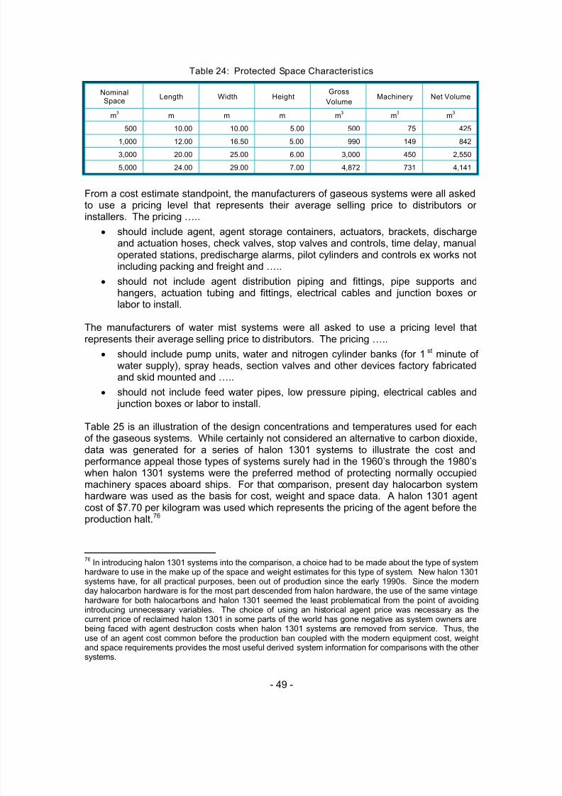
5/9/2018 co2report2 - slidepdf.com
http://slidepdf.com/reader/full/co2report2 57/97
- 49 -
Table 24: Protected Space Characteristics
NominalSpace
Length Width HeightGross
VolumeMachinery Net Volume
m3
m m m m3
m3
m3
500 10.00 10.00 5.00 500 75 425
1,000 12.00 16.50 5.00 990 149 842
3,000 20.00 25.00 6.00 3,000 450 2,550
5,000 24.00 29.00 7.00 4,872 731 4,141
From a cost estimate standpoint, the manufacturers of gaseous systems were all askedto use a pricing level that represents their average selling price to distributors orinstallers. The pricing …..
• should include agent, agent storage containers, actuators, brackets, dischargeand actuation hoses, check valves, stop valves and controls, time delay, manualoperated stations, predischarge alarms, pilot cylinders and controls ex works notincluding packing and freight and …..
• should not include agent distribution piping and fittings, pipe supports andhangers, actuation tubing and fittings, electrical cables and junction boxes orlabor to install.
The manufacturers of water mist systems were all asked to use a pricing level thatrepresents their average selling price to distributors. The pricing …..
• should include pump units, water and nitrogen cylinder banks (for 1st minute ofwater supply), spray heads, section valves and other devices factory fabricatedand skid mounted and …..
• should not include feed water pipes, low pressure piping, electrical cables and junction boxes or labor to install.
Table 25 is an illustration of the design concentrations and temperatures used for eachof the gaseous systems. While certainly not considered an alternative to carbon dioxide,data was generated for a series of halon 1301 systems to illustrate the cost andperformance appeal those types of systems surely had in the 1960’s through the 1980’swhen halon 1301 systems were the preferred method of protecting normally occupiedmachinery spaces aboard ships. For that comparison, present day halocarbon systemhardware was used as the basis for cost, weight and space data. A halon 1301 agentcost of $7.70 per kilogram was used which represents the pricing of the agent before theproduction halt.76
76In introducing halon 1301 systems into the comparison, a choice had to be made about the type of system
hardware to use in the make up of the space and weight estimates for this type of system. New halon 1301systems have, for all practical purposes, been out of production since the early 1990s. Since the modernday halocarbon hardware is for the most part descended from halon hardware, the use of the same vintagehardware for both halocarbons and halon 1301 seemed the least problematical from the point of avoidingintroducing unnecessary variables. The choice of using an historical agent price was necessary as thecurrent price of reclaimed halon 1301 in some parts of the world has gone negative as system owners arebeing faced with agent destruction costs when halon 1301 systems are removed from service. Thus, theuse of an agent cost common before the production ban coupled with the modern equipment cost, weightand space requirements provides the most useful derived system information for comparisons with the othersystems.

5/9/2018 co2report2 - slidepdf.com
http://slidepdf.com/reader/full/co2report2 58/97
- 50 -
Table 25: Design Parameters for the Gaseous Agent Systems77
Generic Name Trade Name Concentration Temperature
HFC-23 FE-13 19.5% 0°C
HFC-227ea FM-200 8.7% 0°C
FK-5-1-12 Novec 1230 5.5% 0°
CIG-541 Inergen 40.0% 0°C
Carbon dioxide - ~34%78 NA
Halon 1301 - 6.0% 0 ° C
11.3.1 System Design Results
Tables 26 through 29 illustrate the space and weight requirements for the agent storagecylinders for the gaseous systems and the pump units, water and nitrogen cylinderbanks (for 1st minute of water supply), section valves and other devices factoryfabricated and skid mounted.
In that regard, the following notes apply to the tables:a. For the gaseous agents, agent weight is the net weight of the agent and is
included in the total weight of the system. For water mist, the agent weight is forthe dedicated potable water supply to provide 30 minutes discharge and is notincluded in the system total weight.
b. Footprint is the area of a square or rectangle circumscribing the agent cylinderbank for the gas systems and the pump skid, water and nitrogen cylinders andother equipment for the water mist system.
c. Cube is the footprint multiplied by the height of the cylinders measured to the topof the valves for gaseous systems and to the top of the uppermost component onthe pump or cylinder skids for the water mist systems.
d. Total weight in the case of the gas systems is the weight of the agent storagecontainers and contents. For the water mist system total weight includes thepump skid, water and nitrogen cylinders and other equipment but does notinclude the potable water supply. Neither include the weight of piping, hangers,etc.
77The concentrations for the halocarbons and inert gases are based on the net volume of the protected
space per IMO requirements. The agent quantities for carbon dioxide and for halon 1301 are based on thegross volume of the protected space, also per IMO requirements.
78The SOLAS regulations for carbon dioxide systems do not use the term “concentration” but instead
require a volume of free carbon dioxide gas equal to either 35% (if including the casing) or 40% (if excludingthe casing) of the gross volume of the protected space. The regulation requires the agent quantitycalculation be performed assuming the free specific volume of carbon dioxide is 0.56 m
3 /kg. For the
purposes of the study estimates, the 40% value was used which provides a residual agent concentration inthe vicinity of 34% when taking into consideration the normal loss of agent from the space during discharge.
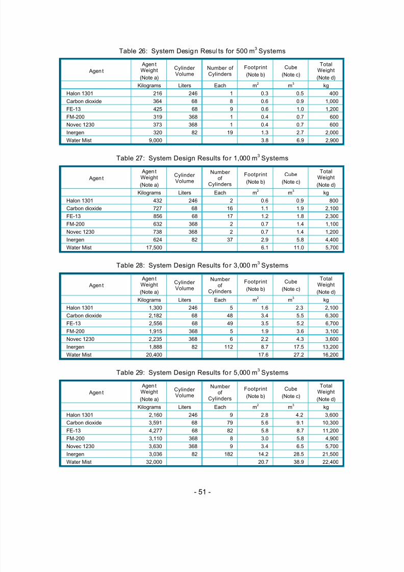
5/9/2018 co2report2 - slidepdf.com
http://slidepdf.com/reader/full/co2report2 59/97
- 51 -
Table 26: System Design Results for 500 m3
Systems
Agent
AgentWeight
(Note a)
CylinderVolume
Number ofCylinders
Footprint
(Note b)
Cube
(Note c)
TotalWeight
(Note d)
Kilograms Liters Each m2
m3
kg
Halon 1301 216 246 1 0.3 0.5 400
Carbon dioxide 364 68 8 0.6 0.9 1,000
FE-13 425 68 9 0.6 1.0 1,200
FM-200 319 368 1 0.4 0.7 600
Novec 1230 373 368 1 0.4 0.7 600
Inergen 320 82 19 1.3 2.7 2,000
Water Mist 9,000 3.8 6.9 2,900
Table 27: System Design Results for 1,000 m3
Systems
Agent
AgentWeight
(Note a)
CylinderVolume
Numberof
Cylinders
Footprint
(Note b)
Cube
(Note c)
TotalWeight
(Note d)
Kilograms Liters Each m2
m3
kg
Halon 1301 432 246 2 0.6 0.9 800
Carbon dioxide 727 68 16 1.1 1.9 2,100
FE-13 856 68 17 1.2 1.8 2,300
FM-200 632 368 2 0.7 1.4 1,100
Novec 1230 738 368 2 0.7 1.4 1,200
Inergen 624 82 37 2.9 5.8 4,400
Water Mist 17,500 6.1 11.0 5,700
Table 28: System Design Results for 3,000 m3
Systems
Agent
AgentWeight
(Note a)
CylinderVolume
Numberof
Cylinders
Footprint
(Note b)
Cube
(Note c)
TotalWeight
(Note d)
Kilograms Liters Each m2 m3 kgHalon 1301 1,300 246 5 1.6 2.3 2,100
Carbon dioxide 2,182 68 48 3.4 5.5 6,300
FE-13 2,556 68 49 3.5 5.2 6,700
FM-200 1,915 368 5 1.9 3.6 3,100
Novec 1230 2,235 368 6 2.2 4.3 3,600
Inergen 1,888 82 112 8.7 17.5 13,200
Water Mist 20,400 17.6 27.2 16,200
Table 29: System Design Results for 5,000 m3
Systems
Agent
AgentWeight
(Note a)
CylinderVolume
Numberof
Cylinders
Footprint
(Note b)
Cube
(Note c)
TotalWeight
(Note d) Kilograms Liters Each m
2m
3kg
Halon 1301 2,160 246 9 2.8 4.2 3,600
Carbon dioxide 3,591 68 79 5.6 9.1 10,300
FE-13 4,277 68 82 5.8 8.7 11,200
FM-200 3,110 368 8 3.0 5.8 4,900
Novec 1230 3,630 368 9 3.4 6.5 5,700
Inergen 3,036 82 182 14.2 28.5 21,500
Water Mist 32,000 20.7 38.9 22,400

5/9/2018 co2report2 - slidepdf.com
http://slidepdf.com/reader/full/co2report2 60/97
- 52 -
11.3.2 System Weight Comparisons
Table 30 is a tabular comparison of the weights of the systems over the range ofvolumes from 500 m3 through 5,000 m3 in terms of percentage additional weight over ahalon 1301 system. Figure 1 is graphical presentation of total system weights for the 4volumes from Tables 26 through 29. Ignoring the halon 1301, it is clear that the FM-200
system is the most weight efficient while the water mist and Inergen systems are 3 timesthe weight of the FM-200 systems. Carbon dioxide and FE-13 equipment weights arenearly identical and Novec 1230 systems are between the FM-200 and carbon dioxideweights.
Table 30: % Weight Comparisons of Systems in 500 – 5,000 m3 Range of Volumes(percentage additional weight when compared to a halon 1301 system)
Agent 500 m3
1,000 m3 3,000 m
3 5,000 m3
Halon 1301 0% 0% 0% 0%
Carbon dioxide 150% 163% 200% 186%
FE-13 200% 188% 219% 211%
FM-200 50% 38% 48% 36%Novec 1230 50% 50% 71% 58%
Inergen 400% 450% 529% 497%
Water Mist 625% 613% 671% 522%
Figure 1: System Weight Comparisons
0
5,000
10,000
15,000
20,000
25,000
0 1,000 2,000 3,000 4,000 5,000 6,000
Protected Volume (m3)
W e i g h t ( k g )
Carbon Dioxide
FE-13
FM-200
Inergen
Novec 1230
Water Mist
Halon 1301
11.3.3 System Footprint Comparisons
Table 31 is a tabular comparison of the footprint or floor / deck space occupied by theagent storage containers for the gaseous systems and the pumping machinery and

5/9/2018 co2report2 - slidepdf.com
http://slidepdf.com/reader/full/co2report2 61/97
- 53 -
accessories for the water mist systems in terms of percentage additional floor area overthat required by a halon 1301 system. Figure 2 is a graphical presentation of the actualfootprint or floor / deck area occupied over the 4 volumes. In this case, both the FM-200and Novec 1230 agent storage cylinder arrangements are less than that required forcarbon dioxide with FE-13 requirements fairly similar to carbon dioxide.
The Inergen and water mist system floor area requirements are significantly more thanthe requirements for the halocarbon or carbon dioxide systems.
Table 31: % Footprint Comparisons of Systems in 500 – 5,000 m3 Range of Volumes(percentage additional floor space when compared to a halon 1301 system)
Agent 500 m3
1,000 m3 3,000 m
3 5,000 m
3
Halon 1301 0% 0% 0% 0%
Carbon dioxide 84% 82% 118% 99%
FE-13 105% 94% 122% 107%
FM-200 20% 20% 19% 6%
Novec 1230 20% 20% 43% 19%
Inergen 327% 365% 459% 404%
Water Mist 1,119% 889% 1,030% 636%
Figure 2: System Footprint Comparisons
0.0
5.0
10.0
15.0
20.0
25.0
0 1,000 2,000 3,000 4,000 5,000 6,000Protected Volume (m3)
E q u i p m e n t F o o t p r i n t ( m 2 )
Carbon Dioxide
FE-13
FM-200
Inergen
Novec 1230
Water Mist
Halon 1301
11.3.4 System Cube Comparisons
Table 32 is a tabular comparison of the volume or cubic space occupied by the agentstorage containers for the gaseous systems and the pumping machinery andaccessories for the water mist systems in terms of percentage additional cubic spaceover that required by a halon 1301 system. Figure 3 is graphical presentation of the

5/9/2018 co2report2 - slidepdf.com
http://slidepdf.com/reader/full/co2report2 62/97
- 54 -
actual volume or cubic space occupied by the systems over the 4 volumes. In this case,the cubic space requirements track quite close the footprint requirements of the varioussystems.
Table 32: % Cube Comparisons of Systems in 500 – 5,000 m3 Range of Volumes(percentage additional cubic space when compared to a halon 1301 system)
Agent 500 m3
1,000 m3 3,000 m
3 5,000 m
3
Halon 1301 0% 0% 0% 0%
Carbon dioxide 100% 101% 140% 119%
FE-13 108% 96% 125% 109%
FM-200 57% 57% 56% 39%
Novec 1230 57% 57% 87% 56%
Inergen 478% 529% 659% 585%
Water Mist 1,398% 1,098% 1,079% 834%
Figure 3: System Cube Comparisons
0.0
5.0
10.0
15.0
20.0
25.0
30.0
35.0
40.0
45.0
0 1,000 2,000 3,000 4,000 5,000 6,000
Protected Volume (m3)
E q u
i p m e n t C u b e ( m 3 )
Carbon Dioxide
FE-13
FM-200
Inergen
Novec 1230
Water MistHalon 1301
11.3.5 Cost Comparisons
Table 33 is an illustration of the comparative costs of the carbon dioxide, halocarbon,inert gas and water mist systems over the range of volumes from 500 m3 through 5,000m3. Figure 4 is a graphical presentation of the same information. The halon 1301costs79 are hypothetical and for reference only.
79The halon 1301 system costs were derived using present day halocarbon system hardware and an agent
cost of $7.70 per kilogram which represents the pricing of the agent from the system manufacturer atsometime before the halon production halt.

5/9/2018 co2report2 - slidepdf.com
http://slidepdf.com/reader/full/co2report2 63/97
- 55 -
Table 33: $ Cost Comparisons of Systems in 500 – 5,000 m3 Range of Volumes
Agent 500 m3
1,000 m3 3,000 m
3 5,000 m3
$ $ $ $
Halon 1301 5,300 7,900 17,300 27,300
Carbon dioxide 11,000 19,000 52,000 83,000
FE-13 22,000 40,000 113,000 187,000
FM-200 16,000 29,000 78,000 126,000
Novec 1230 19,000 37,000 106,000 168,000
Inergen 20,000 34,000 95,000 153,000
Water Mist 60,000 65,000 100,000 130,000
Figure 4: $ Cost Comparisons of Systems in the 500 - 5,000 m3
Range of Volumes
0
20
40
60
80
100
120
140
160
180
200
0 1,000 2,000 3,000 4,000 5,000 6,000
Protected Volume (m3)
C o s t ( $ 0 0 0 )
Carbon Dioxide
FE-13
FM-200
Inergen
Novec 1230
Water Mist
Halon 1301
Another way of looking at the cost comparisons is from a percentage standpoint, usinghalon 1301 systems in the 4 spaces as the base. Table 34 is an illustration of the “costpenalties” the alternative systems carry in terms of percentage over the cost of a halon1301 system.
Table 34 illustrates the scaling effect on costs where, at 500 m3, FM-200 appears to be
the most cost effective alternative to carbon dioxide and water mist the least. Then, at5,000 m3, water mist appears to be the most cost effective alternative to carbon dioxidehaving moved up the ranks from last to first place over the range of volumes.

5/9/2018 co2report2 - slidepdf.com
http://slidepdf.com/reader/full/co2report2 64/97
- 56 -
Table 34: % Cost Comparisons of Systems in 500 – 5,000 m3 Range of Volumes(percentage additional cost when compared to a halon 1301 system)
Agent 500 m3
1,000 m3 3,000 m
3 5,000 m3
Halon 1301 0% 0% 0% 0%
Carbon dioxide 108% 140% 200% 204%
FE-13 315% 406% 553% 585%
FM-200 202% 267% 351% 361%
Novec 1230 259% 368% 513% 515%
Inergen 277% 330% 449% 460%
Water Mist 1,032% 723% 478% 376%
To put this whole cost matter into perspective, those who had historically used halon1301 total flooding systems, who now use carbon dioxide systems for those sameapplications and who are now faced with the prospect of changing to newer alternatives,have experienced ….
• a system cost increase ranging from 100%+ to 180%+ to move from the safety of
halon 1301 systems to carbon dioxide systems and …..
• a further increase in the range of 55% to 65% over the carbon dioxide systemcosts to move from the use of carbon dioxide systems to the safety of the mostcost effective of the alternatives.
The cost comparisons in Tables 33 and 34 show …..
• why the marine industry – in the 1970s - was so supportive of accepting halon1301 systems instead of the then current standard carbon dioxide systems and…..
• why, with the production halt on halon 1301, the preference shifted right back to
carbon dioxide and not to one of the new alternatives.
Clearly, relative cost has to be the largest single objection to the selection of any of theavailable alternatives over carbon dioxide systems, especially in the marine sector.
11.3.6 Cost Comparison Exceptions
In dealing with the system costs, one cannot always directly compare a system againstanother without taking some other relevant matters into consideration. There are threeinstances where some fairly significant changes in costs can take place: The first iswhen selector valves are employed to deal with multiple hazards with the same agentsupply, the second when the system approaches a size where bulk storage of the agentsupply is appropriate and the third when many of the system components are used for
both local application and total flooding purposes.
a. Selector Valve Systems
Carbon dioxide, water and inert gas systems are often configured with selector valvearrangements to use the same agent supply (or pumping capacity in the case of watermist) to protect multiple hazards. In those cases, economics truly favor these multiplehazard capable systems as the cost of the agent supply (or pumping capacity) can beamortized over several applications. The halocarbon agent systems have some selectorvalve capability but with the maximum 10 seconds system discharge time it is often

5/9/2018 co2report2 - slidepdf.com
http://slidepdf.com/reader/full/co2report2 65/97
- 57 -
impossible to use the same agent supply for serve multiple hazards unless they are veryclose together.
In the case of carbon dioxide systems:
• In land based systems a shared agent supply is often the case in aluminum or
steel rolling mills where the carbon dioxide supply serves two purposes:providing agent for the local application system for the rolling machines andagent for the total flooding of normally unoccupied cellars or vaults that containmachinery to support the mill. The agent supply is sized for the largestrequirement and delivered to one or the other application through a selectorvalve arrangement. The assumption here is that only one of the applicationswould require agent at any given time.
• In marine applications, dry cargo and vehicle carrying ships are required to havea total flooding carbon dioxide system to protect the cargo compartment orvehicle spaces. That agent requirement tends to exceed the amount of agentrequired for the engine room. So, once again, it is permitted to use the sameagent supply to serve both the cargo and machinery spaces.
b. Bulk Storage Systems
In both land based and marine systems, at some point in agent weight it becomes moreeconomical to move from high pressure cylinder storage to low pressure bulk storagesystems. All of the comparisons made here have been limited to high pressure carbondioxide systems.
c. Combined Use Systems
In the case of marine systems, in addition to the total flooding system in the machineryspaces, SOLAS regulations now require a local application water system protecting theindividual pieces of hazardous machinery. Much of the same equipment used for a total
flooding water mist system may be shared with the local application water system.Table 35 is an illustration of this matter, where the economic benefits of multi-usesystems are apparent. (Note: in this example the 500 m3 total flooding system has thecapacity to supply the local application system without the addition of any more pumpingcapacity).
Table 35: Equipment Costs of Incorporating IMO MSC/Circ. 913 System
Nominal SpaceWater Mist TotalFlooding System
(only)
Local ApplicationSystem (only)
Water Mist TotalFlooding and WaterLocal ApplicationSystem Combined
IncrementalCost for Local
ApplicationSystem
m3 $ $ $ $500 60,000 8,000 60,000 0
1,000 65,000 30,000 75,000 10,000
3,000 100,000 32,000 110,000 10,000
5,000 130,000 32,000 140,000 10,000

5/9/2018 co2report2 - slidepdf.com
http://slidepdf.com/reader/full/co2report2 66/97
- 58 -
11.3.7 Overall Comparisons and Ranking
Table 36 is a compilation of the simple averages of each of the values from Tables 30,31, 32 and 33 for the percentage weight, footprint, cube and cost comparisonsrespectively. These values serve to approximate the average for each type of system ineach measured category over the 4 volumes of 500, 1,000, 3,000 and 5,000 m3.
Table 36: % Comparisons of Average Values over the 500 to 5,000 m3 Range(Percentage when compared to averages for halon 1301 systems)
Agent Weight Footprint Cube Cost
Halon 1301 0% 0% 0% 0%
Carbon dioxide 175% 96% 115% 163%
FE-13 204% 107% 110% 465%
FM-200 43% 16% 52% 295%
Novec 1230 57% 26% 64% 414%
Inergen 469% 389% 563% 379%
Water Mist 608% 919% 1,102% 652%
Table 37 is merely a ranking of each type of system against the others in eachmeasured category (weight, footprint, cube and cost) from 1 through 7. If one were toassume that …..
• weight, footprint, cube and cost are the only measurable characteristics thatmatter and …..
• each of those characteristics was of equal importance, …..
….. then the ranking of the systems in Table 37 would illustrate the order ofpreference with the hypothetical halon 1301 being the most preferred and water mist theleast preferred.
Table 37: Ranking of Average Values over the 500 to 5,000 m3 Range of Volumes(Relative ranking in each category)
Agent Weight Footprint Cube Cost
ranking ranking ranking ranking
Halon 1301 1 1 1 1
Carbon dioxide 4 4 5 2
FE-13 5 5 4 4
FM-200 2 2 2 3
Novec 1230 3 3 3 6
Inergen 6 6 6 5
Water Mist 7 7 7 7
However, as described in paragraph 11.2.2, there are other characteristics that do noteasily lend themselves to quantification and may well individually or collectively serve asthe basis for system selection. Some of these other characteristics include …..
• water mist systems can be brought into action faster than a gaseous system,thus reducing fire damage, since it is not necessary with the water mist systemsto close openings and shut down ventilation before the start of discharge, …..

5/9/2018 co2report2 - slidepdf.com
http://slidepdf.com/reader/full/co2report2 67/97
- 59 -
• water mist and inert gas agents have more attractive environmental propertiesthan the halocarbons and some of the halocarbons have more attractiveenvironmental properties than other halocarbons, …..
• the gaseous systems usually are limited to a single discharge of agent whereasmost water mist systems have an unlimited water supply in land based
operations and at least 30 minutes of potable water discharge plus after that anunlimited amount of sea water for marine applications, …..
• some halocarbons are considered safer than others depending on how close theuse concentrations come to the point where adverse health effects may beexperienced, …..
• halocarbon agents tend to extinguish fires more rapidly than the longerdischarging carbon dioxide, inert gas or water mist systems and …..
• in high energy fire situations, the halocarbons can experience decomposition,thus creating hydrofluoric acid (HF) whereas decomposition of the agent is not anissue with carbon dioxide, the inert gases nor water mist.
In reviewing the rankings in Table 36, the only advantage carbon dioxide appears tohave over any of the alternatives is cost with several other agents offering significantsavings in weight and space when compared to carbon dioxide.
**********
5/9/2018 co2report2 - slidepdf.com
http://slidepdf.com/reader/full/co2report2 68/97
- 60 -
12 Perceived Issues
In the process of interviewing people knowledgeable on the subject of the use of carbondioxide total flooding systems in normally occupied spaces, it is obvious that viewpointsspanned the full range of positions available on the issue from,
• carbon dioxide total flooding systems are an essential tool for the fire protectioncommunity and nothing should be done to limit their use, to
• use controls are long past due and we must stop this practice of using carbondioxide systems in normally occupied spaces.
In this section we will try to identify the main issues and present, where possible, bothsupporting and opposing views to action on carbon dioxide total flooding systems.
There are 6 topics that continued to be touched on during the interviews with divergentopinions on each …..
• Personnel Safety
• Performance
• Training
• Cost and Availability
• Alternatives
• Technology
12.1 Personnel Safety
The issue with safety is not a question of whether or not carbon dioxide can cause injuryor death at the concentrations used in total flooding systems. Everyone agrees theagent is nearly instantly lethal at those concentrations. The issue is whether or not the
safeguards built into the systems - coupled with the requirements of standards andregulations – are adequate to assure safety to those who work around, visit or transitareas fitted with carbon dioxide systems. In this regard, there are two views ….
12.1.1 Safe enough
There is a strong belief among many that a properly designed, properly serviced totalflooding carbon dioxide system can be safely employed in a normally occupied space ifthe system is equipped with a suitable predischarge alarm and time delay, if there is anadequate evacuation plan and if all who can be exposed to the discharge of the systemare adequately trained to act and respond properly.
The view here is that there have “not been that many” accidents, injuries and deaths that
would warrant considering changing the rules to unnecessarily further limit personnelexposure. Also, before even thinking about use controls, one must weigh the good thatprotection with a carbon dioxide system provides society against the few injuries anddeaths attributable to those systems.
This group points to the new provision of the “lock out” device in the 2000 version ofNFPA 12 as an example of the proactive measures being taken by industry and theconsensus standards process to further enhance the safety of these systems. Further,the view is that there is little more that can or should be done to make these already safesystems safer.

5/9/2018 co2report2 - slidepdf.com
http://slidepdf.com/reader/full/co2report2 69/97
- 61 -
12.1.2 Unsafe under any conditions
The opposing view is that carbon dioxide total flooding systems are unsafe under anyconditions. The record of accidents and deaths is a testament to this and an indictmentof all who promote, design, install, regulate or buy these systems for use in normallyoccupied spaces.
This group takes issue with and considers flippant approach presented by promotersthat simply more changes to existing “safeguards” can make these systems significantlysafer. Further, this group feels the industry and its trade associations have done a poor job of adequately advising the public about the safety risks related to carbon dioxidesystems. They pointed out an industry association publication which extols the merits ofcarbon dioxide systems without one word about the safety risks inherent in thesesystems.80
Both the US Navy and the US Army have stopped the practice of installing new carbondioxide systems out of concern for the safety of some of the finest trained people in theworld. So why is it that we - in the civilian sector - think it is appropriate to use thesesystems around people who are often unaware about the risks presented? This is
especially true in the marine sector where the issue of inadequate crew training is thesubject of continuous debate.
Finally, how is it that two NFPA standards, 12 and 2001, have such diverging views onwhat is and what isn’t safe? The inconsistency between these two standards, withrespect to the requirements for personnel safety, is both illogical and impossible todefend.
12.2 Performance
The issue of performance centers on whether one perceives or does not perceivecarbon dioxide to be a unique, irreplaceable system. …..
12.2.1 Carbon dioxide is unique
One view holds that the attributes and performance of carbon dioxide systems areunique when compared to other systems employing alternatives. This view asserts thatthere are no other agents that can protect such a wide range of applications, and anyaction to limit the use of carbon dioxide would put numerous lives and unmeasurableproperty value at risk in the event of a fire. The design flexibility with selector valves andcentral storage are not available with the halocarbons; neither inert gas nor thehalocarbons are very effective on deep seated class A fires and none of the alternativescan be used in local application modes.
12.2.2 Other agents can do the same
The other view is that, while carbon dioxide may well be unique and no single other
agent replace it in all (its) applications, there is an entire portfolio of other agent systemsthat collectively can perform as well as and often times better than carbon dioxide inmost plausible total flooding applications. Inert gas and water mist systems can employselector valves as readily as carbon dioxide and water is the most effective agent ondeep seated class A fires. From a technical standpoint, it is difficult to envision anycarbon dioxide total flooding system application that could not be readily handled byother agent systems. Water mist is displacing carbon dioxide in the protection of turbine
80 “Why Carbon Dioxide (CO2) in Fire Suppression Systems?” at http://www.fssa.net/library-r.shtml and
http://www.nafed.org/library/whyCO2.cfm

5/9/2018 co2report2 - slidepdf.com
http://slidepdf.com/reader/full/co2report2 70/97
- 62 -
enclosures and diesel generators. The only area of weakness for alternatives is in localapplication, which really is not the subject as the issue is the safe use of total floodingsystems.
12.3 Training
In looking at this question of the safety of carbon dioxide systems, the thought waspresented by several that increased training might reduce the accident rate. Onceagain, there are different views on this …..
12.3.1 Training is the answer
One view is that many of the accidents described in the earlier EPA report on carbondioxide systems could have easily been avoided by more training on installation,maintenance and service practices. Some suggested a certification program forinstallers and servicing companies to make sure those who work around these systemsare properly qualified. Over time, the core group of people who were proficient withcarbon dioxide systems have retired or gone on to different things at all levels in theindustry from the manufacturers to the distributors to the installing and servicing
companies to the end user. So today we have new players without a lot of experience.If we train them, the accident rate will drop.
12.3.2 Training is a good idea, but not the answer
The other view is that training is always a good idea, but the repeated mentions oftraining highlights a disturbing reality. If the lack of training is considered a significantcause of our carbon dioxide related accidents, what do we think our accident experienceis going to be like going forward as we retire additional experienced people and end upwith fewer trained people? Is the industry willing to make the investments necessary toconsistently support and conduct the proper training at all levels on these systems?
12.4 Cost and Availability
Virtually everyone agrees that the major attractions of carbon dioxide systems are lowcost and high availability. While there is agreement here, there are different views onthe value of low cost, high availability.
12.4.1 Low cost is great
One view is that carbon dioxide systems are the best deal around as the halocarbon andinert gas systems can cost twice as much for a new system. Further, the recharge costsof a carbon dioxide system are inconsequential when compared to the halocarbons.What is equally important though are some of the hidden costs in dealing with thealternatives. Carbon dioxide is a known entity and everyone understands the rules forthe design and installation and acceptance of these systems. That’s not the case with
the alternatives because they are new and some of the requirements may still be opento conflicting interpretations. This is especially true in the shipbuilding industry wherethere are numerous influences on a project ranging from the owner, the architect, theshipyard, the classification society, the USCG, etc. Questions on the alternatives at anyof these levels very easily translate into delays in ship construction.
12.4.2 You get what you pay for
The other view is that the costs of the carbon dioxide systems are so low that some ofthe essential support that should be bundled with the system are deliberately eliminatedfrom the scope so one can bid a competitive price. When a product settles to a

5/9/2018 co2report2 - slidepdf.com
http://slidepdf.com/reader/full/co2report2 71/97
- 63 -
commodity level – as carbon dioxide systems have in many instances – then it is in noone’s short term economic interests to incur additional costs supporting that line. It hasbeen a learning experience with the systems using alternatives, but it was that way withhalon 1301 in the late 1960’s and many made it through that era quite successfully.
Speaking of hidden costs, those system manufacturers, distributors, installers or owners
who have been found responsible, even partially, in an accidental death or injury with acarbon dioxide system will never forget either the experience or the cost. Many feel thatthe profit earned or money saved by selling or buying carbon dioxide systems – whensafer alternatives are available – is inconsequential when compared to the potentialliability costs associated with even partial responsibility for a single injury or death.
12.5 Alternatives
In considering alternatives to carbon dioxide, those who really do not want to considerthem have a long list of reasons, some right on target and the others quite unlikely.Those on the other side of the issue acknowledge many of these reasons and addressthem ……
12.5.1 Alternatives have problemsOne side of this issue feels that the alternatives are really troublesome. First of all, thereare too many of them and most people do not have the time or inclination to sort themout. This is compounded by the competitive spirit of self promoting product informationwhich often include less than subtle negative connotations of competitors’ products. Asa result, after talking to all the promoters, the end user is completely conversant in all thenegative attributes of all alternatives.
In addition, there are several specific concerns, such as inert gas and halocarbonsystems can kill too if not designed right. There is a concern about the halocarbons andthe environment and concerns about halocarbons and decomposition. Also, manymentioned that the alternatives are not as proven as carbon dioxide.
12.5.2 Sure, but don’t rule them out
The other side feels this type of criticism of the alternatives is just a replay of what wenton in the late 1960’s and early 1970’s when the forces of carbon dioxide met those ofhalon 1301 in the battle of the market place. In that instance, however, there was onlyone alternative, and the collective halon 1301 forces prevailed. This side wishes therewere fewer alternatives too. As time marches on, that will be the case as somealternatives have already emerged as leaders and others have failed or are headed inthat direction.
The focus on possible, but implausible, safety issues with the inert gases andhalocarbons is not credible. The comment about the alternatives not being as proven asan agent that has been in commercial use since 1929 was acknowledged as probably
true, but irrelevant.
12.6 Technology
Some feel the reason we find ourselves insisting that carbon dioxide continues to beessential is because we have had only limited success on the technology front. As thereis no obvious way to reach the goal of a cost effective replacement for carbon dioxidesystems, why even start down that path? Further, who needs it – we have carbondioxide!

5/9/2018 co2report2 - slidepdf.com
http://slidepdf.com/reader/full/co2report2 72/97
- 64 -
While manufacturers and government organizations have done much work to developchemical alternatives to halons, everything brought to market to date is so expensivethat some have lost hope of finding a cost effective replacement for either halon 1301 orcarbon dioxide (with the carbon dioxide presumably being an easier economic target).On the equipment manufacturers side, with a few exceptions, the approach has beenlimited to putting the new (very expensive) agents into existing hardware, re-labeling it
and going to market.
Some have mentioned goals like ……
• continue the work on chemical agent development and find one able to (safely)compete on an installed cost basis with carbon dioxide total flooding systems, ..
• focus development efforts on more cost effective agent storage and deliverysystems for really inexpensive agents like water and inert gases or …...
• do both.
This is an area that needs a renewed effort on the part of all stakeholders.
**********
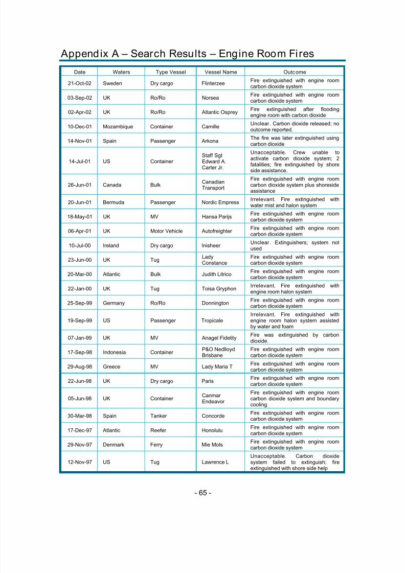
5/9/2018 co2report2 - slidepdf.com
http://slidepdf.com/reader/full/co2report2 73/97
- 65 -
Appendix A – Search Results – Engine Room Fires
Date Waters Type Vessel Vessel Name Outcome
21-Oct-02 Sweden Dry cargo FlinterzeeFire extinguished with engine roomcarbon dioxide system
03-Sep-02 UK Ro/Ro Norsea
Fire extinguished with engine room
carbon dioxide system
02-Apr-02 UK Ro/Ro Atlantic OspreyFire extinguished after floodingengine room with carbon dioxide
10-Dec-01 Mozambique Container CamilleUnclear. Carbon dioxide released; nooutcome reported.
14-Nov-01 Spain Passenger ArkonaThe fire was later extinguished usingcarbon dioxide
14-Jul-01 US ContainerStaff SgtEdward A.Carter Jr.
Unacceptable. Crew unable toactivate carbon dioxide system; 2fatalities; fire extinguished by shoreside assistance.
26-Jun-01 Canada BulkCanadianTransport
Fire extinguished with engine roomcarbon dioxide system plus shoresideassistance
20-Jun-01 Bermuda Passenger Nordic Empress Irrelevant. Fire extinguished withwater mist and halon system
18-May-01 UK MV Hansa ParijsFire extinguished with engine roomcarbon dioxide system
06-Apr-01 UK Motor Vehicle AutofreighterFire extinguished with engine roomcarbon dioxide system
10-Jul-00 Ireland Dry cargo InisheerUnclear. Extinguishers; system notused
23-Jun-00 UK TugLadyConstance
Fire extinguished with engine roomcarbon dioxide system
20-Mar-00 Atlantic Bulk Judith LitricoFire extinguished with engine roomcarbon dioxide system
22-Jan-00 UK Tug Toisa GryphonIrrelevant. Fire extinguished withengine room halon system
25-Sep-99 Germany Ro/Ro Donnington Fire extinguished with engine roomcarbon dioxide system
19-Sep-99 US Passenger TropicaleIrrelevant. Fire extinguished withengine room halon system assistedby water and foam
07-Jan-99 UK MV Anagel FidelityFire was extinguished by carbondioxide.
17-Sep-98 Indonesia ContainerP&O NedlloydBrisbane
Fire extinguished with engine roomcarbon dioxide system
29-Aug-98 Greece MV Lady Maria TFire extinguished with engine roomcarbon dioxide system
22-Jun-98 UK Dry cargo ParisFire extinguished with engine roomcarbon dioxide system
05-Jun-98 UK Container
Canmar
Endeavor
Fire extinguished with engine room
carbon dioxide system and boundarycooling
30-Mar-98 Spain Tanker ConcordeFire extinguished with engine roomcarbon dioxide system
17-Dec-97 Atlantic Reefer HonoluluFire extinguished with engine roomcarbon dioxide system
29-Nov-97 Denmark Ferry Mie MolsFire extinguished with engine roomcarbon dioxide system
12-Nov-97 US Tug Lawrence LUnacceptable. Carbon dioxidesystem failed to extinguish; fireextinguished with shore side help

5/9/2018 co2report2 - slidepdf.com
http://slidepdf.com/reader/full/co2report2 74/97
- 66 -
Date Waters Type Vessel Vessel Name Outcome
20-Oct-97 UK Reefer BolivarUnacceptable. Carbon dioxidesystem depleted and fighting fire withwater. Outcome not reported.
10-May-97 UK MV Danica SunriseFire extinguished with engine roomcarbon dioxide system
21-Apr-97 Angola Container MaditerraneaFire extinguished with engine roomcarbon dioxide system
06-Jan-97 Canada Tanker Le SauleFire extinguished with engine roomcarbon dioxide system
06-Jan-97 UK Ferry AchieveFire extinguished with engine roomcarbon dioxide system
03-Jan-97 UK Ferry AchieveFire on board Achieve smotheredusing vessel's carbon dioxide system
06-Aug-96 Puerto Rico Ro/Ro Kent AtlanticFire extinguished with engine roomcarbon dioxide system
11-May-96 Bahamas Passenger Discovery
Unclear. Fire extinguishing effortsunclear but fire could not be put outby ship crew but had to be put outwith shore side assistance.
08-Feb-96 Canada Fishing Judith Suzanne
Unacceptable. Carbon dioxidesystem diminished when crew opendoor prematurely. Crew not trained infirefighting.
24-Jan-96 Bangladesh MV Banglar RobiFire extinguished with engine roomcarbon dioxide system
30-Oct-95 US Ferry BillikinUnacceptable. Carbon dioxideunable to extinguish fire. Salvorbrought in to extinguish the blaze.
07-Sep-95 UK MV Jan-WillemUnclear. Fire out but report did notsay how.
18-May-95 Singapore Container Planeta
Unclear. Sent message "cannotreach CO2 equipment" then 3 hourslater reported fire was under control;outcome unclear.
23-Jan-95 US Container POL AmericaFire extinguished with engine roomcarbon dioxide system
04-Dec-94 Italy BulkKhudozhnikToidze
Fire extinguished with engine roomcarbon dioxide system and shorebrigades
17-Oct-94 UK Bulk RisnesIrrelevant. Fire extinguished withengine room halon system
26-Jul-94 US Bulk Forum ChemistFire extinguished with engine roomcarbon dioxide system
07-Jun-94 Saudi Arabia TankerNejmat el PetrolXXII
Fire extinguished with pump roomcarbon dioxide system
02-Jun-94 Libya Tanker Esso DemetiaFire extinguished with engine roomcarbon dioxide system
13-Dec-93 UK Ro/RoNormanCommodore
Unacceptable. Fire still burning 8hours after release of engine roomcarbon dioxide system; no outcomereported.
01-Dec-93 Mombosa MVMaritaLeonhardt
Fire extinguished with engine roomcarbon dioxide system
27-May-93 UK Fishing Calvados
Unacceptable. Crew initially triedfighting fire with carbon dioxidesystem but was forced to abandonvessel due to smoke
14-Apr-93 New Zealand MVCapitaineTasman
Fire extinguished with engine roomcarbon dioxide system

5/9/2018 co2report2 - slidepdf.com
http://slidepdf.com/reader/full/co2report2 75/97
- 67 -
Date Waters Type Vessel Vessel Name Outcome
05-Aug-92 Greece Container Norasia AtticaFire extinguished with engine roomcarbon dioxide system
02-Jul-92 China Bulk Berge CharlotteUnacceptable. Carbon dioxidedischarged without success. Firecontrolled by cooling with seawater.
16-Jan-92 Atlantic Reefer GeestbayFire extinguished with engine roomcarbon dioxide system
27-Nov-91 UK Ferry Morning SunFire extinguished with engine roomcarbon dioxide system
19-Sep-91 Canada Bulk DocevirgoFire extinguished with engine roomcarbon dioxide system
05-Aug-91 St. Lucia Reefer GeestcapeFire extinguished with engine roomcarbon dioxide system
01-Aug-91 Thailand MV Jutha MaleeFire extinguished with engine roomcarbon dioxide system
08-Jun-91 Nigeria Container BoringiaFire extinguished with engine roomcarbon dioxide system

5/9/2018 co2report2 - slidepdf.com
http://slidepdf.com/reader/full/co2report2 76/97
- 68 -
Appendix B – OSHA Technical Bulletin
Technical Information Bulletin
U.S. Department of LaborOccupational Safety and Health Administration
Total Flooding Carbon Dioxide (CO2)
Fire Extinguishing SystemTIB 01-
Purpose
This Technical Information Bulletin informs users of total flooding carbon dioxide (CO2) fire-extin-
guishing systems of a condition that poses a serious hazard to employees.
Background
The New York Regional Office brought to the attention of the Directorate of Technical Support thepotential hazards of carbon dioxide intoxication for employees inside a vault protected by a total flooding
CO2
fire-extinguishing system. The Manhattan Area Office investigated an accident in which an employee
of a securities firm died from CO intoxication. The employee was inside the vault with the vault door
closed and locked. When the employee pulled a manual fire alarm actuation device that was located inside
the vault space, it activated the warning alarm and the total flooding CO2
system.
Description of the Accident
An account administrator at a securities firm was working overtime in a section of a vault. At 7:10
p.m., security personnel closed and locked the vault. The employee was working in a section of the vault
accessible only with a swipe card. The security guard did not have a swipe card and did not access that
area of the vault, but instead looked through a small window and apparently did not see the employee.
The employee discovered that the vault was locked shortly thereafter. There was a phone in the vault, and
the employee apparently tried unsuccessfully to call for help. At about 7:35 p.m., the employee pulled a
manual fire alarm system actuation device. In addition to sounding an alarm, the device instantly acti-
vated a total flooding CO2
fire-extinguishing system. Activation of the CO2
system created an atmosphere
immediately dangerous to life and health inside the locked vault. Using self-contained breathing apparatus
(SCBA), firefighters recovered the employee’s body. The cause of death, as ruled by the medical exam-
iner, was accidental CO2
intoxication.
Accident Investigation
OSHA’s accident investigation revealed violations of OSHA’s means of egress and fire protect
standards, including 29 CFR 1910.36 (b)(1), 1910.160(b)(5), 1910.160(c)(1), and 1910.160(c)(3). The
The Occupational Safety and Health Administration’s (OSHA’s) Directorate of Technical Support issTechnical Information Bulletins (TIBs) to provide information about occupational hazards and/or to pro-
vide information about noteworthy, innovative, or specialized procedures, practices, and research that
relate to occupational safety and health. These bulletins are not standards or regulations and they create
independent legal obligations. They are advisory in nature, informational in content, and are intended to
assist employers in providing a safe and healthful workplace.
Further information about this bulletin may be obtained by contacting OSHA’s Directorate of
Technical Support at 202-693-2095.

5/9/2018 co2report2 - slidepdf.com
http://slidepdf.com/reader/full/co2report2 77/97
- 69 -
National Fire Protection Association (NFPA) standard on carbon dioxide extinguishing systems (NFPA-
12, 2000) also addresses these conditions.
The investigation found that the extinguishing system was interlocked with the vault door. The syste
would only discharge if the door was shut. The manual pull station was located inside the vault. Pulling
the device with the door open sounds the alarm; however, no CO2
is discharged until the vault door is close
There were no warning signs at the entrance to the vault indicating the hazard of the total flooding CO2
system. There also was no label on the pull station to indicate that once activated, there would be
a discharge of total flooding CO2
into the vault and to describe the resultant hazard to personnel.
The employer explained that the system’s configuration was intended to permit employees to pull the
manual actuation device, exit the vault, and close the door behind them. The employer further explained
that the pull station was installed inside the space to prevent employees from activating the system while
others were in the vault. However, if the manual station is pulled when the door is already shut, as was the
case in this accident, there is an immediate discharge of the CO2.
The NFPA-12, 2000 standard requires that the normal manual controls for the CO2
system actuation b
located for easy accessibility at all times, including the time of fire. It does not specify whether the location
should be inside or outside of the protected space. The 18th
edition of the NFPA Fire Protection Handbook
requires that the manual controls be located to avoid confusion, and they must be clearly
labeled with safe operating procedures. However, it also contains schematics for a total flooding CO2 systethat depict the manual actuation device outside of the protected space and next to the entrance.
During the rescue operation, a problem arose when the fire department needed quick access to the
vault space. Firefighters were unable to execute a rescue until a securities firm employee was able to open
vault door.
Conclusions
The employer did not meet the requirements of 29 CFR 1910.160 and NFPA-12 standards that
require: a warning be posted at the entrance to the vault space, as well as inside the vault, regarding the
function of the total flooding CO2
system and its hazards to personnel; warning signs be posted at the
manual actuation station to warn employees about the hazards associated with the total flooding CO2
system; employees who work inside vault spaces be trained with respect to the potential hazard in the
protected spaces and the proper safety precautions to be observed before manually actuating the system.Further, the employer did not provide an emergency action plan in accordance with 29 CFR 1910.38, and
did not provide a pre-discharge employee alarm in accordance with 29 CFR 1910.160 that complies with
29 CFR 1910.165. Finally, NFPA-12, 2000 requires, in part, that means be provided for the “ prompt
rescue of any trapped personnel.” The employer failed to meet this requirement.
Recommendations
• Fixed CO2
extinguishing systems should be installed and maintained in accordance with NFPA-12,
2000 standards.
• Equip the pull station device, installed inside a vault, with a control circuit to ensure that actuating the
pull station will initiate activation of the CO2
fire-extinguishing system only if the vault door is open at
the time of actuation and that no discharge of CO2
will occur until the vault door is subsequently closed
In addition, the control circuit should disable the manual pull station from activating the extinguishing
system if the vault door is already closed.
• Ensure that employees have safe and readily available means of evacuation. In unique situations, such
as those associated with vaults, alternative protective means such as an emergency intercom system,
sign-in log, video or manual-surveillance, and a procedure to ensure that all other employees have
cleared all vault spaces before actuating the alarm and fire-extinguishing system and before closing the
vault doors, should be communicated, implemented, and followed.

5/9/2018 co2report2 - slidepdf.com
http://slidepdf.com/reader/full/co2report2 78/97
- 70 -
• Post emergency numbers near vault and enclosed space telephones.
• Install signs at the entrance to and inside the protected space indicating the presence of extinguishing
systems which can present CO2
intoxication and suffocation hazards to employees.
• Properly mark/label pull stations and other actuation devices to indicate their function and the potential
hazard to personnel.
• Insure that total flooding systems have a pre-discharge alarm which provides employees with sufficient
time to safely exit the space.
• Train all employees with respect to: the type of systems installed in the workplace, the hazards involved
proper activation in case of emergency, and the correct response to audible and visual pre-discharge
alarms. Provide training for non-English speaking employees in languages understood by the affected
employees and other individuals that may be exposed to the hazard.
• Provide a system or device that can be secured in the closed position to prevent accidental or deliberate
discharge when persons not familiar with the system (outside vendors and contractors) and its operation
are present in a protected space.
• 29 CFR 1910.160(b)(6) requires annual inspection to check that the system is maintained in good
operating condition. We also recommend inspection of the system for compliance with NFPA and
OSHA requirements.
If the total flooding CO2
extinguishing systems are installed by employers to meet a particular OSHA
standard, employers must:
• comply with provisions of 29 CFR 1910.162, Fixed extinguishing systems, gaseous agent;
• comply with provisions of 29 CFR 1910.160, Fixed extinguishing systems, general. Among the
requirements in this standard is the obligation in Paragraph 29 CFR 1910.160 (b)(17) that requires
employers to, “ provide and assure the use of PPE needed for immediate rescue.” Employers will need
to designate and train individuals how to properly wear an SCBA and perform rescue.
Additional Information
• NFPA-12, Section 1-6, Personnel Safety, contains requirements to protect personnel.
• NFPA-12, Appendix A-1-6, “The steps and safeguards necessary to prevent injury or death to personne
areas whose atmospheres will be made hazardous by the discharge of carbon dioxide ....” is not a part ofthe requirements of NFPA-12. It is presented for informational purposes only. However, the appen-
dix includes provisions which can be used to safeguard personnel and prevent injury or death.
• U.S. Environmental Protection Agency report, “Carbon Dioxide as a Fire Suppressant: Examining the
Risks,” contains valuable information for raising awareness and promoting the responsible use of CO2
fire suppression systems. See http://www.epa.gov.
*

5/9/2018 co2report2 - slidepdf.com
http://slidepdf.com/reader/full/co2report2 79/97
- 71 -
Appendix C - Excerpt from NFPA Standard 12
Standard Related Appendix Material
1-6* Personnel Safety. A-1-6 The steps and safeguards necessary toprevent injury or death to personnel in areas
whose atmospheres will be made hazardous bythe discharge of carbon dioxide can include thefollowing provisions:(1) Adequate aisleways and routes of exit andkeeping them clear at all times(2) Necessary additional or emergency lighting,or both, and directional signs to ensure quick,safe evacuation(3) Alarms within such areas that will operateimmediately upon activation of the system ondetection of the fire, with the discharge of thecarbon dioxide and the activation of automaticdoor closures delayed for sufficient time toevacuate the area before discharge begins(4) Only outward swinging, self-closing doors at
exits from hazardous areas, and, where suchdoors are latched, provision of panic hardware(5) Continuous alarms at entrances to suchareas until atmosphere has been restored tonormal(6) Odor, which is added to the carbon dioxideso that hazardous atmospheres in such areascan be recognized(7) Warning and instruction signs at entrancesto and inside such areas(8) Prompt discovery and rescue of personsrendered unconscious in such areas (This canbe accomplished by having such areassearched by trained personnel equipped with
proper breathing equipment immediately aftercarbon dioxide discharge stops. Thosepersons rendered unconscious by carbondioxide can be restored without permanentinjury by artificial respiration, if removed quicklyfrom the hazardous atmosphere. Self-containedbreathing equipment and personnel trained inits use, and in rescue practices includingartificial respiration, should be readilyavailable.)(9) Instruction and drills of all personnel withinor in the vicinity of such areas, includingmaintenance or construction people who canbe brought into the area, to ensure their correctaction when carbon dioxide protective
equipment operates(10) Means for prompt ventilation of such areas(Forced ventilation will often be necessary.Care should be taken to really dissipatehazardous atmospheres and not merely movethem to another location. Carbon dioxide isheavier than air.)(11) Other steps and safeguards that arenecessary to prevent injury or death asindicated by a careful study of each particularsituation

5/9/2018 co2report2 - slidepdf.com
http://slidepdf.com/reader/full/co2report2 80/97
- 72 -
Standard Related Appendix Material
1-6.1 Hazards to Personnel. The discharge ofcarbon dioxide in fire-extinguishingconcentration creates serious hazards topersonnel, such as suffocation and reduced
visibility during and after the discharge period.Consideration shall be given to the possibility ofcarbon dioxide drifting and settling into adjacentplaces outside of the protected space (see 1- 6.1.1). Consideration shall also be given towhere the carbon dioxide can migrate or collectin the event of a discharge from a safety reliefdevice of a storage container.
1-6.1.1* In any use of carbon dioxide,consideration shall be given to the possibilitythat personnel could be trapped in or enter intoan atmosphere made hazardous by a carbondioxide discharge. Suitable safeguards shall beprovided to ensure prompt evacuation, to
prevent entry into such atmospheres, and toprovide means for prompt rescue of anytrapped personnel. Personnel training shall beprovided. Predischarge alarms shall beprovided except as noted in 1-8.1(c) and 1-8.3.5.
A-1-6.1.1 It is recommended that self-containedbreathing apparatus be provided for rescuepurposes.
1-6.1.2 The following represent typical signs.
1-6.1.2.1 Appropriate warning signs shall beaffixed in a conspicuous location.
(1) Typical sign in every protected spaceWARNING
CARBON DIOXIDE GASWHEN ALARM OPERATES VACATE
IMMEDIATELY
(2) Typical sign at every entrance to protectedspace
WARNING
CARBON DIOXIDE GASWHEN ALARM OPERATES DO NOT ENTER
UNTILVENTILATED
(3) Typical sign in every nearby space where
carbon dioxide can accumulate to hazardouslevelsCAUTION
CARBON DIOXIDE DISCHARGE INTO ANEARBY
SPACE CAN COLLECT HERE. WHEN ALARMOPERATES VACATE IMMEDIATELY

5/9/2018 co2report2 - slidepdf.com
http://slidepdf.com/reader/full/co2report2 81/97
- 73 -
Standard Related Appendix Material
(4) Typical sign outside each entrance tocarbon dioxide storage rooms
CAUTIONCARBON DIOXIDE GAS
VENTILATE THE AREA BEFORE ENTERING.AHIGH CARBON DIOXIDE GAS
CONCENTRATIONCAN OCCUR IN THIS AREA AND CAN
CAUSESUFFOCATION
1-6.1.2.2 Appropriate warning signs shall beplaced at every location where manualoperation of the system can occur. A typicalsign at each manual actuation station is asfollows:
WARNINGACTUATION OF THIS DEVICE WILL CAUSE
CARBON DIOXIDE TO DISCHARGE.BEFORE
ACTUATING, BE SURE PERSONNEL ARECLEAR
OF THE AREA
1-6.1.3 All persons that can at any time enter aspace protected by carbon dioxide shall bewarned of the hazards involved, given an alarmsignal, and provided with safe evacuationprocedures. (See 1-8.5.)
1-6.1.4 The predischarge warning signal shallprovide a time delay of sufficient duration to
allow for evacuation under worst-caseconditions, except as noted in 1-8.1(c) and 1-8.3.5. Dry runs shall be made to determine theminimum time needed for persons to evacuatethe hazard area, allowing time to identify thewarning signal.
1-6.1.5 Audible and visual predischarge signalsshall be provided, except as noted in 1-8.1(c)and 1-8.3.5.
1-6.1.6 All personnel shall be informed thatdischarge of carbon dioxide gas from eitherhigh- or low-pressure systems directly at aperson will endanger the person’s safety bycausing eye injury, ear injury, or even falls dueto loss of balance upon the impingement of thehigh velocity discharging gas. Contact withcarbon dioxide in the form of dry ice can causefrostbite.
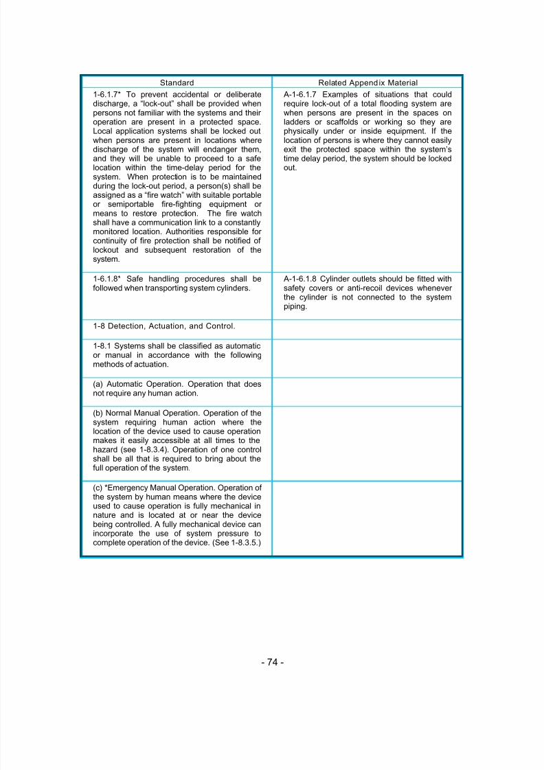
5/9/2018 co2report2 - slidepdf.com
http://slidepdf.com/reader/full/co2report2 82/97
- 74 -
Standard Related Appendix Material
1-6.1.7* To prevent accidental or deliberatedischarge, a “lock-out” shall be provided whenpersons not familiar with the systems and theiroperation are present in a protected space.
Local application systems shall be locked outwhen persons are present in locations wheredischarge of the system will endanger them,and they will be unable to proceed to a safelocation within the time-delay period for thesystem. When protection is to be maintainedduring the lock-out period, a person(s) shall beassigned as a “fire watch” with suitable portableor semiportable fire-fighting equipment ormeans to restore protection. The fire watchshall have a communication link to a constantlymonitored location. Authorities responsible forcontinuity of fire protection shall be notified oflockout and subsequent restoration of thesystem.
A-1-6.1.7 Examples of situations that couldrequire lock-out of a total flooding system arewhen persons are present in the spaces onladders or scaffolds or working so they are
physically under or inside equipment. If thelocation of persons is where they cannot easilyexit the protected space within the system’stime delay period, the system should be lockedout.
1-6.1.8* Safe handling procedures shall befollowed when transporting system cylinders.
A-1-6.1.8 Cylinder outlets should be fitted withsafety covers or anti-recoil devices wheneverthe cylinder is not connected to the systempiping.
1-8 Detection, Actuation, and Control.
1-8.1 Systems shall be classified as automaticor manual in accordance with the followingmethods of actuation.
(a) Automatic Operation. Operation that doesnot require any human action.
(b) Normal Manual Operation. Operation of thesystem requiring human action where thelocation of the device used to cause operationmakes it easily accessible at all times to thehazard (see 1-8.3.4). Operation of one controlshall be all that is required to bring about thefull operation of the system.
(c) *Emergency Manual Operation. Operation ofthe system by human means where the deviceused to cause operation is fully mechanical innature and is located at or near the devicebeing controlled. A fully mechanical device canincorporate the use of system pressure tocomplete operation of the device. (See 1-8.3.5.)

5/9/2018 co2report2 - slidepdf.com
http://slidepdf.com/reader/full/co2report2 83/97
- 75 -
Standard Related Appendix Material
1-8.3.5* All valves controlling the release anddistribution of carbon dioxide shall be providedwith an emergency manual control. This shallnot apply to slave high-pressure cylinders. The
emergency means shall be easily accessibleand located close to the valves controlled.Determination shall be made as to whether atime delay and predischarge alarm foremergency manual control are required basedon the nature of the hazard and safetyrequirements. Where there is no time delay orpredischarge alarm with emergency manualmethod of actuation, it shall be ascertained thatthe hazard area and adjoining areas wherecarbon dioxide can accumulate are clear of allpersonnel prior to operation of this device.These devices shall be clearly marked toindicate this concept with a warning placard.

5/9/2018 co2report2 - slidepdf.com
http://slidepdf.com/reader/full/co2report2 84/97
- 76 -
Appendix D - Excerpt from NFPA Standard 2001
Standard Related Appendix Material
1-6 Safety.
1-6.1* Hazards to Personnel
1-6.1.1 * Any agent that is to be recognized by
this standard or proposed for inclusion in thisstandard shall first be evaluated in a mannerequivalent to the process used by the U.S.Envi-ronmental Protection Agency's (EPA)SNAP Program.
A-1-6.1 Potential hazards to be considered forindividual systems are the following:
(a) Noise. Discharge of a system can cause
noise loud enough to be startling but ordinarilyinsufficient to cause traumatic injury.
(b) Turbulence. High-velocity discharge fromnozzles could be sufficient to dislodgesubstantial objects directly in the path. Systemdischarge can cause enough generalturbulence in the enclosures to moveunsecured paper and light objects.
(c) Cold Temperature. Direct contact with thevaporizing liquid being discharged from asystem will have a strong chilling effect onobjects and can cause frostbite burns to theskin. The liquid phase vaporizes rapidly whenmixed with air and thus limits the hazard to the
immediate vicinity of the discharge point. Inhumid atmospheres, minor reduction in visibilitycan occur for a brief period due to thecondensation of water vapor.
A-1-6.1.1 The discharge of clean agentsystems to extinguish a fire could create ahazard to personnel from the natural form of theclean agent or from the products ofdecomposition that result from exposure of theagent to the fire or hot surfaces. Unnecessaryexposure of personnel either to the naturalagent or to the decomposition products shouldbe avoided.
The SNAP Program was originally outlined in59FR 13044.
1-6.1.2* Halocarbon Agents.
1-6.1.2.1 Any unnecessary exposure tohalocarbon clean agents, even at NOAELconcentrations, and halocarbon decompositionproducts shall be avoided. The requirement forpre-discharge alarms and time delays areintended to pre-vent human exposure toagents. The following additional pro-visionsshall apply in order to account for failure ofthese safeguards:
(a) Halocarbon systems for spaces that arenormally occupied and designed to
concentrations up to the NOAEL (see Table 1- 6.1.2.1(a)) shall be permitted.
(b) Halocarbon systems for spaces that arenormally occupied and designed toconcentrations above the NOAEL and up to theLOAEL (see Table 1-6.1.2.1(a)), shall bepermitted, given that means be provided to limitexposure to no longer than the time specified inTables 1-6.1.2.1 (b) through 1-6.1.2.1 (e) cor-responding to the given design concentration.
A-1-6.1.2 Table A-1-6.1.2(a) providesinformation on the toxicological effects ofhalocarbon agents covered by this standard.The NOAEL is the highest concentration atwhich no adverse physiological ortoxicological effect has been observed. TheLOAEL is the lowest concentration at which anadverse physiological or toxicological effect hasbeen observed.
An appropriate protocol measures the effect ina stepwise manner such that the intervalbetween the LOAEL and NOAEL is sufficientlysmall to be acceptable to the competent
regulatory authority. The EPA includes in itsSNAP evaluation this aspect (of the rigor) of thetest protocol.
………. Continued >>>>>
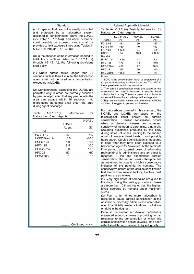
5/9/2018 co2report2 - slidepdf.com
http://slidepdf.com/reader/full/co2report2 85/97
- 77 -
Standard Related Appendix Material
(c) In spaces that are not normally occupiedand protected by a halocarbon systemdesigned to concentrations above the LOAEL(see Table 1-6.1.2.1(a)), and where personnelcould possibly be exposed, means shall beprovided to limit exposure times using Tables 1-6.1.2.1 (b) through 1-6.1.2.1 (e).
(d) In the absence of the information needed tofulfill the conditions listed in 1-6.1.2.1 (a)through 1-6.1.2.1(c), the fol-lowing provisionsshall apply:
(1) Where egress takes longer than 30seconds but less than 1 minute, the halocarbonagent shall not be used in a concentrationexceeding its LOAEL.
(2) Concentrations exceeding the LOAEL arepermitted only in areas not normally occupied
by personnel provided that any personnel in thearea can escape within 30 seconds. Nounprotected personnel shall enter the areaduring agent discharge.
Table 1-6.1.2.1(a) Information forHalocarbon Clean Agents
NOAELLOAEL
Agent (%)(%)
FC-3-1-10 40 >40
HCFC Blend A 10.0 >10.0
HCFC-124 1.0 2.5
HFC-125 7.5 10.0
HFC-227ea 9.0 10.5
HFC-23 50 >50
HFC-236fa 10 15
………. Continued >>>>>
Table A-1-6.1.2 (a) Toxicity Information forHalocarbon Clean Agents
LC50 or ALC NOAEL LOAEL
Agent (%) (%) (%)
FC-2-1-8 >81 30 >30
FC-3-1-10 >80 40 >40FIC-13I1 >12.8 0.2 0.4
HCFC 64 10.0 >10.0
Blend A
HCFC-124 23-29 1.0 2.5
HFC-125 >70 7.5 10.0
HFC-227ea >80 9.0 10.5HFC-23 >65 50 >50
HFC-236fa >18.9 10 15
Notes:
1. LC50 is the concentration lethal to 50 percent of arat population during a 4-hour exposure. The ALC isthe approximate lethal concentration.
2. The cardiac sensitization levels are based on theobservance or non-observance of serious heart
arrhythmias in a dog. The usual protocol is a 5-minuteexposure followed by a challenge with epinephrine.
3. High concentration values are determined with theaddition of oxygen to prevent asphyxiation.
For halocarbons covered in this standard, theNOAEL and LOAEL are based on thetoxicological effect known as cardiacsensitization. Cardiac sensitization occurswhen a chemical causes an increasedsensitivity of the heart to adrenaline, a naturallyoccurring substance produced by the bodyduring times of stress, leading to the suddenonset of irregular heart beats and possiblyheart attack. Cardiac sensitization is measured
in dogs after they have been exposed to ahalocarbon agent for 5 minutes. At the 5-minutetime period, an external dose of adrenaline(epinephrine) is administered and an effect isrecorded, if the dog experiences cardiacsensitization. The cardiac sensitization potentialas measured in dogs is a highly conservativeindicator of the potential in humans. Theconservative nature of the cardiac sensitizationtest stems from several factors, the two mostpertinent are as follows:
(1) Very high doses of adrenaline are given tothe dogs during the testing procedure (dosesare more than 10 times higher than the highestlevels secreted by humans under maximum
stress.(2) Four to ten times more halocarbon isrequired to cause cardiac sensitization in theabsence of externally administered adrenaline,even in artificially created situations of stressor fright in the dog test.
Because the cardiac sensitization potential ismeasured in dogs, a means of providing humanrelevance to the concentration at which thiscardiac sensitization occurs (LOAEL) has beenestablished through the use of physiologically

5/9/2018 co2report2 - slidepdf.com
http://slidepdf.com/reader/full/co2report2 86/97
- 78 -
Standard Related Appendix Material
Table 1-6.1.2.1(b) Time for Safe HumanExposure at Stated
Concentrations for HFC-125
HFC-125
Concentration
Human Exposure Time% v/v ppm (minutes)
7.5 75,000 5.00
8.0 80,000 5.00
8.5 85,000 5.00
9.0 90,000 5.00
9.5 95,000 5.00
10.0 100,000 5.00
10.5 105,000 5.00
11.0 110,000 5.00
11.5 115,000 5.00
12.0 120,000 1.67
12.5 125,000 0.59
13.0 130,000 0.5413.5 135,000 0.49
Notes:
1. Data derived from the EPA-approved and peer-reviewed physiologically based pharmacokinetic(PBPK) model or its equivalent.
2. Based on LOAEL of 10.0 percent in dogs.
Table 1-6.1.2.1 (c) Time for Safe HumanExposure at Stated Concentrations for HFC-227ea
HFC-227ea
Concentration
Human Exposure
% v/v ppm Time (minutes)
9.0 90,000 5.009.5 95,000 5.00
10.0 100,000 5.00
10.5 105,000 5.00
11.0 110,000 1.13
11.5 115,000 0.60
12.0 120,000 0.49
Notes:
1. Data derived from the EPA-approved and peer-reviewed PBPK model or its equivalent.
2. Based on LOAEL of 10.5 percent in dogs.
………. Continued >>>>>
based pharmacokinetic (PBPK) modeling.
A PBPK model is a computerized tool thatdescribes time-related aspects of a chemical'sdistribution in a biological system. The PBPKmodel mathematically describes the uptake ofthe halocarbon into the body and thesubsequent distribution of the halocarbon to theareas of the body where adverse effects canoccur. For example, the model describes thebreathing rate and uptake of the halocarbonfrom the exposure atmosphere into the lungs.From there, the model uses the blood flowbathing the lungs to describe the movement ofthe halocarbon from the lung space into thearterial blood that directly feeds the heart andvital organs of the body.
It is the ability of the model to describe thehalocarbon concentration in human arterialblood that provides it primary utility in relatingthe dog cardiac sensitization test results to a
human who is unintentionally exposed to thehalocarbon. The concentration of halocarbon inthe dog arterial blood at the time the cardiacsensitization event occurs (5-minute exposure)is the critical arterial blood concentration, andthis blood parameter is the link to the humansystem. Once this critical arterial bloodconcentration has been measured in dogs, theEPA-approved PBPK model simulates howlong it will take the human arterial bloodconcentration to reach the critical arterial bloodconcentration (as determined in the dog test)during human inhalation of any particularconcentration of the halocarbon agent. As longas the simulated human arterial concentration
remains below the critical arterial bloodconcentration, the exposure is considered safe.Inhaled halo-carbon concentrations thatproduce human arterial blood concentrationsequal to or greater than the critical arterialblood concentration are considered unsafebecause they represent inhaled concentrationthat potentially yield arterial bloodconcentrations where cardiac sensitizationevents occur in the dog test. Using these criticalarterial blood concentrations of halocarbons asthe ceiling for allowable human arterialconcentrations, any number of halocarbonexposure scenarios can be evaluated using thismodeling approach.
For example, in the dog cardiac sensitizationtest on Halon 1301, a measured dog arterialblood concentration of 25.7 mg/l is measured atthe effect concentration (LOAEL) of 7.5 percentafter a 5-minute exposure to Halon 1301 andan external intravenous adrenaline injection.

5/9/2018 co2report2 - slidepdf.com
http://slidepdf.com/reader/full/co2report2 87/97
- 79 -
Standard Related Appendix Material
1-6.1.3* Inert Gas Clean Agents. Unnecessaryexposure to inert gas agent systems resulting inlow oxygen atmospheres shall be avoided. Therequirement for pre-discharge alarms and timedelays is intended to prevent human exposureto agents. The following additional provisionsshall apply in order to account for failure ofthese safeguards:
(a) Inert gas systems designed toconcentrations below 43 percent(corresponding to an oxygen concentration of12 percent, sea level equivalent of oxygen)shall be permitted, given the following:
(1) The space is normally occupied.
(2) Means are provided to limit exposure to nolonger than 5 minutes.
(b) Inert gas systems designed toconcentrations between 43 and 52 percent
(corresponding to between 12 and 10 percentoxygen, sea level equivalent of oxygen) shallbe permitted, given the following:
(1) The space is normally unoccupied.
(2) Means are provided to limit exposure to nolonger than 3 minutes.
(c) Inert gas systems designed toconcentrations between 52 and 62(corresponding to between 10 and 8 percentoxygen, sea level equivalent of oxygen) shallbe permitted given the following:
(1) The space is normally unoccupied.
(2) Where personnel could possibly beexposed, means are provided to limit the exposure
(d) Inert gas systems designed toconcentrations above 62 percent(corresponding to 8 percent oxygen or below,sea level equivalent of oxygen), shall only beused in unoccupied areas where personnel arenot exposed to such oxygen depletion. (See 3- 5.3.3 for atmospheric correction factors.)
1-6.1.4 Safety Requirements
1-6.1.4.1 * Suitable safeguards shall beprovided to ensure prompt evacuation of and
prevent entry into hazardous atmospheres andalso to provide means for prompt rescue of anytrapped personnel. Safety items such aspersonnel training, warning signs, dischargealarms, self-contained breathing apparatus(SCBA), evacuation plans, and fire drills shallbe considered.
1-6.1.4.2* Consideration shall be given to thepossibility of a clean agent migrating toadjacent areas outside of the protected space.
A-1-6.1.3 Table A-1-6.1.3 provides informationon physiological effects of inert gas agentscovered by this standard. The health concernfor inert gas clean agents is asphyxiation dueto the lowered oxygen levels. With inert gasagents, an oxygen concentration of no lessthan 12 percent (sea level equivalent) isrequired for normally occupied areas. Thiscorresponds to an agent concentration of nomore than 43 percent.
Table A-1-6.1.3 Physiological Effects forInert Gas Agents
No Effect Low Effect
Level* Level*
Agent (%) (%)
IG-01 43 52
IG-100 43 52
IG-55 43 52IG-541 43 52
*Based on physiological effects in humans inhypoxic atmospheres. These values are thefunctional equivalents of NOAEL and LOAELvalues and correspond to 12-percent minimumoxygen for the No Effect Level and 10-percentminimum oxygen for the Low Effect Level.
IG-541 uses carbon dioxide to promotebreathing characteristics intended to sustain lifein the oxygen-deficient environment for
protection of personnel. Care should be usednot to design inert gas-type systems fornormally occupied areas using designconcentrations higher than that specified in thesystem manufacturer's listed design manual forthe hazard being protected.
Inert gas agents do not decompose measurablyin extinguishing a fire. As such, toxic orcorrosive decomposition products are notfound. However, heat and breakdown productsof the fire itself can still be substantial and couldmake the area untenable for human occupancy.

5/9/2018 co2report2 - slidepdf.com
http://slidepdf.com/reader/full/co2report2 88/97
- 80 -
Appendix E - Excerpt from OSHA Regulations
Regulations (Standards - 29 CFR)Fixed extinguishing systems, general. - 1910.160Subpart L - Fire ProtectionStandard 1910.160 - Fixed extinguishing systems, general
1910.160(a) Scope and application.
1910.160(a)(1) This section applies to all fixed extinguishing systems installed to meet a particularOSHA standard except for automatic sprinkler systems which are covered by 1910.159.
1910.160(a)(2) This section also applies to fixed systems not installed to meet a particular OSHAstandard, but which, by means of their operation, may expose employees to possibleinjury, death, or adverse health consequences caused by the extinguishing agent. Such
systems are only subject to the requirements of paragraphs (b)(4) through (b)(7) and (c)of this section.
1910.160(a)(3) Systems otherwise covered in paragraph (a)(2) of this section which are installed inareas with no employee exposure are exempted from the requirements of this section.
1910.160(b) General requirements.
1910.160(b)(1) Fixed extinguishing system components and agents shall be designed and approved foruse on the specific fire hazards they are expected to control or extinguish.
1910.160(b)(2) If for any reason a fixed extinguishing system becomes inoperable, the employer shallnotify employees and take the necessary temporary precautions to assure their safetyuntil the system is restored to operating order. Any defects or impairments shall beproperly corrected by trained personnel.
1910.160(b)(3) The employer shall provide a distinctive alarm or signaling system which complies with1910.165 and is capable of being perceived above ambient noise or light levels, on allextinguishing systems in those portions of the workplace covered by the extinguishingsystem to indicate when the extinguishing system is discharging. Discharge alarms arenot required on systems where discharge is immediately recognizable.
1910.160(b)(4) The employer shall provide effective safeguards to warn employees against entry intodischarge areas where the atmosphere remains hazardous to employee safety or health.
1910.160(b)(5) The employer shall post hazard warning or caution signs at the entrance to, and insideof, areas protected by fixed extinguishing systems which use agents in concentrationsknown to be hazardous to employee safety and health.
1910.160(b)(6)
5/9/2018 co2report2 - slidepdf.com
http://slidepdf.com/reader/full/co2report2 89/97
- 81 -
The employer shall assure that fixed systems are inspected annually by a personknowledgeable in the design and function of the system to assure that the system ismaintained in good operating condition.
1910.160(b)(7) The employer shall assure that the weight and pressure of refillable containers is
checked at least semi-annually. If the container shows a loss in net content or weight ofmore than 5 percent, or a loss in pressure of more than 10 percent, it shall be subjectedto maintenance.
1910.160(b)(8) The employer shall assure that factory charged nonrefillable containers which have nomeans of pressure indication are weighed at least semi-annually. If a container shows aloss in net weight or more than 5 percent it shall be replaced.
1910.160(b)(9) The employer shall assure that inspection and maintenance dates are recorded on thecontainer, on a tag attached to the container, or in a central location. A record of the lastsemi-annual check shall be maintained until the container is checked again or for the life
of the container, whichever is less.1910.160(b)(10) The employer shall train employees designated to inspect, maintain, operate, or repairfixed extinguishing systems and annually review their training to keep them up-to-date inthe functions they are to perform.
1910.160(b)(11) The employer shall not use chlorobromomethane or carbon tetrachloride as anextinguishing agent where employees may be exposed.
1910.160(b)(12) The employer shall assure that systems installed in the presence of corrosiveatmospheres are constructed of non-corrosive material or otherwise protected against
corrosion.1910.160(b)(13) Automatic detection equipment shall be approved, installed and maintained inaccordance with 1910.164.
1910.160(b)(14) The employer shall assure that all systems designed for and installed in areas withclimatic extremes shall operate effectively at the expected extreme temperatures.
1910.160(b)(15) The employer shall assure that at least one manual station is provided for dischargeactivation of each fixed extinguishing system.
1910.160(b)(16) The employer shall assure that manual operating devices are identified as to the hazardagainst which they will provide protection.
1910.160(b)(17) The employer shall provide and assure the use of the personal protective equipmentneeded for immediate rescue of employees trapped in hazardous atmospheres createdby an agent discharge.
1910.160(c) Total flooding systems with potential health and safety hazards to employees.
5/9/2018 co2report2 - slidepdf.com
http://slidepdf.com/reader/full/co2report2 90/97
- 82 -
1910.160(c)(1) The employer shall provide an emergency action plan in accordance with 1910.38 foreach area within a workplace that is protected by a total flooding system which providesagent concentrations exceeding the maximum safe levels set forth in paragraphs (b)(5)and (b)(6) of 1910.162.
1910.160(c)(2) Systems installed in areas where employees cannot enter during or after the system'soperation are exempt from the requirements of paragraph (c) of this section.
1910.160(c)(3) On all total flooding systems the employer shall provide a pre-discharge employee alarmwhich complies with 1910.165, and is capable of being perceived above ambient light ornoise levels before the system discharges, which will give employees time to safely exitfrom the discharge area prior to system discharge.
1910.160(c)(4) The employer shall provide automatic actuation of total flooding systems by means of anapproved fire detection device installed and interconnected with a pre-discharge
employee alarm system to give employees time to safely exit from the discharge areaprior to system discharge.[45 FR 60711, Sept. 12, 1980]<break>(Not included: Fixed extinguishing systems, dry chemical. - 1910.161)
<break>
Regulations (Standards - 29 CFR)Fixed extinguishing systems, gaseous agent. - 1910.162Subpart L - Fire ProtectionStandard 1910.162 - Fixed extinguishing systems, gaseous agent
1910.162(a) Scope and application -
1910.162(a)(1) Scope. This section applies to all fixed extinguishing systems, using a gas as theextinguishing agent, installed to meet a particular OSHA standard. These systems shallalso comply with 1910.160. In some cases, the gas may be in a liquid state duringstorage.
1910.162(a)(2) Application. The requirements of paragraphs (b)(2) and (b)(4) through (b)(6) shall applyonly to total flooding systems.
1910.162(b) Specific requirements.
1910.162(b)(1) Agents used for initial supply and replenishment shall be of the type approved for thesystem's application. Carbon dioxide obtained by dry ice conversion to liquid is notacceptable unless it is processed to remove excess water and oil.
1910.162(b)(2) Except during overhaul, the employer shall assure that the designed concentration ofgaseous agents is maintained until the fire has been extinguished or is under control.

5/9/2018 co2report2 - slidepdf.com
http://slidepdf.com/reader/full/co2report2 91/97
- 83 -
1910.162(b)(3) The employer shall assure that employees are not exposed to toxic levels of gaseousagent or its decomposition products.
1910.162(b)(4) The employer shall assure that the designed extinguishing concentration is reached
within 30 seconds of initial discharge except for Halon systems which must achievedesign concentration within 10 seconds.
1910.162(b)(5) The employer shall provide a distinctive pre-discharge employee alarm capable of beingperceived above ambient light or noise levels when agent design concentrations exceedthe maximum safe level for employee exposure. A pre-discharge employee alarm foralerting employees before system discharge shall be provided on Halon 1211 andcarbon dioxide systems with a design concentration of 4 percent or greater and forHalon 1301 systems with a design concentration of 10 percent or greater. The pre-discharge employee alarm shall provide employees time to safely exit the dischargearea prior to system discharge.
1910.162(b)(6) 1910.162(b)(6)(i) Where egress from an area cannot be accomplished within one minute, the employershall not use Halon 1301 in concentrations greater than 7 percent.
1910.162(b)(6)(ii) Where egress takes greater than 30 seconds but less than one minute, the employershall not use Halon 1301 in a concentration greater than 10 percent.
1910.162(b)(6)(iii) Halon 1301 concentrations greater than 10 percent are only permitted in areas notnormally occupied by employees provided that any employee in the area can escapewithin 30 seconds. The employer shall assure that no unprotected employees enter the
area during agent discharge.[45 FR 60712, Sept. 12, 1980; 46 FR 24557, May 1, 1981]

5/9/2018 co2report2 - slidepdf.com
http://slidepdf.com/reader/full/co2report2 92/97
- 84 -
Appendix F - Excerpt from ISO Standard 6183
5 Safety requirements
In any proposed use of carbon dioxide extinguishing systems where there is a possibilitythat people may be trapped in or enter into the protected area, suitable safeguards shall
be pro vided to ensure prompt evacuation of the area, to restrict entry into the area afterdischarge, except where necessary to provide means for prompt rescue of any trappedpersonnel. Such safety aspects as personnel training, warning signs, discharge alarms,and breaching apparatus shall be considered. The following requirements shall be takeninto account:
a) Provision of exit routes which shall be kept clear at all times and the provision ofadequate direction signs;
b) Provision of alarms within such areas that are distinctive from all other alarm signalsand that will operate immediately upon detection of the fire and release of the carbondioxide (see clause 6);
c) Provision of only outward swinging self-closing doors which shall be openable from
the inside even when locked from the outside;
d) Provision of continuous visual and audible alarms entrances, until the atmospherehas been made safe;
e) Provision for adding an odour to the carbon dioxide so that hazardous atmospheresmay be recognized;
f) Provision of warning and instruction signs at entrances;
g) Provision of self-contained breathing equipment and personnel trained in its use;
h) Provision of a means of ventilating the areas after extinguishing the fire;
6 Warning alarmsAn audible alarm shall be provided on all total flooding systems, and on local floodingsystems where dispersal of the carbon dioxide from the system into the room would givea concentration of more than 5 %. The alarm shall sound during any delay periodbetween fire detection and discharge and throughout the discharge.
The sound intensity of the alarm described in 5 b) shall be such that it will be heardabove the average local noise level; where this is abnormally high, visual indication shallalso be provided.
Alarm devices shall be supplied from an energy source sufficient to allow continuousOperation of the warning alarm for a minimum of 30 min.
NOTE - Alarms may not be necessary for local application systems, unless the quantity of carbon dioxidedischarged relative to the room volume is capable of producing a concentration in excess of 5 %.
<break>
10 Precautions for Iow-lying parts of protected areas
Where it is possible for carbon dioxide gas to collect in pits, wells, shaft bottoms or otherlow-lying areas, consideration shall be given to adding an odoriferous substance to the

5/9/2018 co2report2 - slidepdf.com
http://slidepdf.com/reader/full/co2report2 93/97
- 85 -
carbon dioxide, and/or to providing additional ventilation systems to remove the carbondioxide after discharge.
<break>
11 Safety signs
For all total flooding systems, and those local application systems which may causecritical concentrations, a warning notice shall be displayed on the inside and outside ofevery door to the protected area.
The notice shall warn that, in case of alarm or discharge of carbon dioxide, personnelshould leave the room immediately and not enter again before the room has beenthoroughly ventilated because of the danger of suffocation.
12 Precautions during maintenance work
On automatic total flooding systems, protecting normally unoccupied rooms, provisionshall be made for the prevention of automatic discharge during periods of entry by
personnel where they may not be able to leave the room during any delay period (secclause 6).
NOTE - This precaution is not usually necessary for local application systems but should be provided wherehazardous concentrations may be produced in any area which may be occupied.

5/9/2018 co2report2 - slidepdf.com
http://slidepdf.com/reader/full/co2report2 94/97
- 86 -
Appendix G - Excerpt from IMO FSS Code
CHAPTER 5 - FIXED GAS FIRE-EXTINGUISHING SYSTEMS
1 Application
This chapter details the specifications for fixed gas fire-extinguishing systems asrequired by chapter II-2 of the Convention.
<break>
2 Engineering specifications
<break>
2.1.3 System control requirements
2.1.3.1 The necessary pipes for conveying fire-extinguishing medium into the protectedspaces shall be provided with control valves so marked as to indicate clearly the spacesto which the pipes are led. Suitable provision shall be made to prevent inadvertentrelease of the medium into the space. Where a cargo space fitted with a gas fire-extinguishing system is used as a passenger space, the gas connection shall be blankedduring such use. The pipes may pass through accommodations providing that they areof substantial thickness and that their tightness is verified with a pressure test, after theirinstallation, at a pressure head not less than 5 N/mm2. In addition, pipes passingthrough accommodation areas shall be joined only by welding and shall not be fitted withdrains or other openings within such spaces. The pipes shall not pass throughrefrigerated spaces.
2.1.3.2 Means shall be provided for automatically giving audible warning of the releaseof fire-extinguishing medium into any ro-ro spaces and other spaces in which personnelnormally work or to which they have access. The pre-discharge alarm shall beautomatically activated (e.g., by opening of the release cabinet door). The alarm shalloperate for the length of time needed to evacuate the space, but in no case less than 20s before the medium is released. Conventional cargo spaces and small spaces (such ascompressor rooms, paint lockers, etc.) with only a local release need not be providedwith such an alarm.
2.1.3.3 The means of control of any fixed gas fire-extinguishing system shall be readilyaccessible, simple to operate and shall be grouped together in as few locations aspossible at positions not likely to be cut off by a fire in a protected space. At eachlocation there shall be clear instructions relating to the operation of the system havingregard to the safety of personnel.
2.1.3.4 Automatic release of fire-extinguishing medium shall not be permitted, except aspermitted by the Administration.
2.2 Carbon dioxide systems
<break>
5/9/2018 co2report2 - slidepdf.com
http://slidepdf.com/reader/full/co2report2 95/97
- 87 -
2.2.2 Controls
Carbon dioxide systems shall comply with the following requirements:
.1 two separate controls shall be provided for releasing carbon dioxide into aprotected space and to ensure the activation of the alarm. One control
shall be used for opening the valve of the piping which conveys the gasinto the protected space and a second control shall be used to dischargethe gas from its storage containers; and
.2 the two controls shall be located inside a release box clearly identified forthe particular space. If the box containing the controls is to be locked, akey to the box shall be in a break-glass-type enclosure conspicuouslylocated adjacent to the box.
<break>
2.5 Equivalent fixed gas fire-extinguishing systems for machinery spaces and
cargo pump rooms
Fixed gas fire-extinguishing systems equivalent to those specified in paragraphs 2.2 to2.4 shall be approved by the Administration based on the guidelines developed by theOrganization.81
81Refer to the Revised guidelines for the approval of equivalent fixed gas fire-extinguishing systems, as
referred to in SOLAS 74, for machinery spaces and cargo pump rooms (MSC/Circ.848).

5/9/2018 co2report2 - slidepdf.com
http://slidepdf.com/reader/full/co2report2 96/97
- 88 -
Appendix H – Proposal for NFPA 12
NFPA Technical Committee Document Proposal Form
NOTE: All Proposals Must Be Received By 5:00 P.M. EST/EDST On The Published Proposal Closing Date.
For further information on the standards-making process, please contactCodes and Standards Administration at 617-984-7249
For technical assistance, please call NFPA at 617-770-3000
FOR OFFICE USE ONLY
Log #:
Date Rec'd:
Please indicate in which format you wish to receive your ROP/ROC electronic paper download (Note: In choosing the download option you intend to view the ROP/ROC from our Website; no copy will be sent to you.)
Date June 20, 2003 Name Robert T. Wickham, P.E. Tel. No. 603-772-3229
Company Wickham Associates
Street Address 9 Winding Brook Drive City Stratham State NH Zip 03885
Please Indicate Organization Represented (if any) N/A
1. a) NFPA Document Title Standard on Carbon Dioxide Extinguishing Systems
b) NFPA No. & Edition NFPA 12 - 2000 c) Section/Paragraph 1-6
2. Proposal recommends: (check one) new text revised text deleted text
3. Proposal (include proposed new or revised wording, or identification of wording to be deleted): (Note: Proposedtext should be in legislative format: i.e., use underscore to denote wording to be inserted (inserted wording) and strike-
through to denote wording to be deleted (deleted wording).
Carbon dioxide total flooding systems shall not be used in normally occupied areas.
4. Statement of Problem and Substantiation for Proposal: (Note: State the problem that will be resolved by your
recommendation; give the specific reason for your proposal including copies of tests, research papers, fire experience,etc. If more than 200 words, it may be abstracted for publication.)
The proliferation of carbon dioxide total flooding systems used in normally occupied spaces andthe continuing incidences of deaths and injuries caused by the accidental discharge of thesesystems are very serious concerns. Fire suppression systems should not be the cause of deathsespecially in the event of accidental system discharges. (See reverse for continuation …..).
5. This Proposal is original material. (Note: Original material is considered to be the submitter’s own idea
based on or as a result of his/her own experience, thought, or research and, to the best of his/her knowledge, is not
copied from another source.)
This Proposal is not original material, its source (if known) is as follows:
I hereby grant the NFPA all and full rights in copyright, in this proposal, and I understand that I acquire no rights in
any publication of NFPA in which this proposal in this or another similar or analogous form is used.
Signature (Required)
PLEASE USE SEPARATE FORM FOR EACH PROPOSAL • NFPA Fax: (617) 770-3500
Mail to: Secretary, Standards Council, National Fire Protection Association
1 Batterymarch Park, P.O. Box 9101, Quincy, MA 02269

5/9/2018 co2report2 - slidepdf.com
http://slidepdf.com/reader/full/co2report2 97/97
- 89 -
NFPA Technical Committee Document Proposal Form
Continuation Sheet
Date: June 20, 2003Name: Robert T. Wickham, P.E.
Telephone: 603-772-3229Company: Wickham AssociatesAddress: 9 Winding Brook DriveCity: StrathamState: NHZip: 03885
1 a) NFPA Document Title: Standard on Carbon Dioxide Extinguishing Systems1 b) NFPA No. & Edition: NFPA 12-20001 c) Section / Paragraph: 1-6 / 1-6.1
3. Proposal: Carbon dioxide total flooding systems shall not be used in normallyoccupied areas.
4. Statement of Problem and Substantiation for Proposal: The proliferation ofcarbon dioxide total flooding systems used in normally occupied spaces and thecontinuing incidences of deaths and injuries caused by the accidental discharge of thesesystems are very serious concerns. Fire suppression systems should not be the causeof deaths especially in the event of accidental system discharges. Prohibiting the use ofcarbon dioxide total flooding systems in normally occupied spaces addresses this directthreat to public health and safety.
The US EPA report ("Carbon Dioxide as a Fire Suppressant: Examining the Risks,"Report EPA430-R-00-002, United States Environmental Protection Agency, Washington,DC: February 2000.) clearly documents the accident record of carbon dioxide systems.
Two copies of that report are enclosed and additional copies can be downloaded fromthe US EPA web-site at http://www.epa.gov/ozone/snap/fire/co2/co2report.pdf .