co united states 0 onuclear regulatory commission
TRANSCRIPT

P• , fkI> P R E G ( /J .,4
CO "UNITED STATES 0 oNUCLEAR REGULATORY COMMISSION t WASHINGTON, D.C. 20555-0001
November 19, 1999
LICENSEE: GPU Nuclear, Inc.
FACILITY: Three Mile Island Nuclear Station, Unit 1 (TMI-1)
SUBJECT: SUMMARY OF OCTOBER 27,1999, MEETING WITH GPU NUCLEAR, INC. REGARDING CONTROL ROD PERFORMANCE ISSUES AT TMI-1 (TAC NO. MA2823)
On October 27, 1999, a public meeting was held between the U.S. Nuclear Regulatory Commission (NRC), Framatome Cogema Fuels (FCF), and GPU Nuclear, Inc., (GPUN or the licensee) at NRC Headquarters, Two White Flint North, 11545 Rockville Pike, Rockville, MD. The purpose of the meeting was to discuss control rod performance issues related to the TMI-1 September 11, 1999, event where two control rods failed to fully insert on initial insertion during control rod drop time testing. Attachment 1 is a list of attendees. Attachment 2 is a copy of the licensee's handout used at the meeting. A copy of the licensee's proprietary slide used at the meeting is being withheld from public disclosure in accordance with 10 CFR 2.790.
The licensee presented information regarding the description and design of the system, the safety significance of the event and the root cause analysis efforts. The presentation included other plant experience both foreign and domestic, data collection efforts for both rod insertion times and control rod assembly drag forces, as well as several other parameters, and proposed corrective actions. The licensee concluded that the event was of low safety significance, and that the TMI-1 plant operated within its design basis during cycle 12. While a definitive root cause has not yet been found, the licensee and FCF believe that the cause is related to a combination of complex fuel assembly bowing and excessive guide tube deformation. The licensee made improvements to the cycle 13 core to minimize the same quadrant residence and fuel assembly distortion. The licensee believes continuous operation is justified for cycle 13 but committed to perform rod drop time testing for all shutdowns when testing has not been performed within 4 months. The licensee will submit a supplemental licensee event report within 18 months evaluating new data and will make its determination as to whether additional monitoring is warranted.
The Babcok & Wilcox Owners Group (B&WOG) is closely following this event and plans to meet again with the staff in December 1999 to discuss additional rod drop time data from the Crystal River 3 and Oconee 2 outages. The B&WOG Core Performance Committee is overseeing the progress of the FCF root cause analysis and will make recommendations regarding the generic implications of the event as the analysis is completed.

November 19, 1999
-2
The staff thanked GPUN and FCF for their very detailed presentation. The staff recognized the significant amount of work involved in evaluating and presenting the data for this event.
Original signed by:
Timothy G. Colburn, Sr. Project Manager, Section 1 Project Directorate I Division of Licensing Project Management Office of Nuclear Reactor Regulation
Docket No. 50-289
Attachments: 1. List of attendees 2. GPUN/FCF Handout - Incomplete Rod Insertion Event of
September 11, 1999
cc w/atts: See next page
DISTRIBUTION:
HARD COPY
PUBLIC OGC PDI-1 Rdg. ACRS
E-MAIL PEselgroth, RI (PWE) SPeterson (SRP) EAdensam (EGA1) JZwolinski/SBlack (JAZ/SCB) RCaruso (RXC)
DLaBarge (DEL) MTschiltz (MDT) MChatterton (MSC1) LWiens (LAW) TColburn (TGC) MO'Brien (MOB)
SBailey (SNB)
DOCUMENT NAME: G:\PDI-1\TMI-1\MTS1027.WPD To receive a copy of this document, indicate in the box: "C" = Copy without attachment/enclosure "E" = Copy with attachment/enclosure "N" = No copy
OFFICE PDI-1/PM PDI-1/LA// SRXB/SC I IPDi-i/sI NAME TColburn:lcc MO'BrienlfY, A RCaruso Q SPete rs-" DATE 1'/l' 99 / I99 (ii/11 n/ t/r/799 I\ AI /99
OFF IAL RECORD COPY

November 19, 1999
-2
The staff thanked GPUN and FCF for their very detailed presentation. The staff recognized the significant amount of work involved in evaluating and presenting the data for this event.
Original signed by:
Timothy G. Colburn, Sr. Project Manager, Section 1 Project Directorate I Division of Licensing Project Management Office of Nuclear Reactor Regulation
Docket No. 50-289
Attachments: 1. List of attendees 2. GPUN/FCF Handout - Incomplete Rod Insertion Event of
September 11, 1999
cc w/atts: See next page
DISTRIBUTION:
HARD COPY File Center PUBLIC OGC PDI-1 Rdg. ACRS
E-MAIL PEselgroth, RI (PWE) SPeterson (SRP) EAdensam (EGA1) JZwolinski/SBIack (JAZ/SCB) RCaruso (RXC)
D aBarge (DEL) MTschiltz (MDT) MChatterton (MSC1) LWiens (LAW) TColburn (TGC) MO'Brien (MOB)
SBailey (SNB)
DOCUMENT NAME: G:\PDI-1\TMI-1\MTS1027.WPD To receive a copy of this document, indicate in the box: "C" = Copy without attachment/enclosure "E" = Copy with attachment/enclosure "N" = No copy
TColburn:lcc MO'Brie RCarusol SPeters' Ri
1( /6/ 99 // 99 /1,/ /7/99 I\ RECOR /99 / 'OFFI._ IAL RECORD COPY
I UL4OFFICE
NAME
DATE I1

-2-
The staff thanked GPUN and FCF for their very detailed presentation. The staff recognized the significant amount of work involved in evaluating and presenting the data for this event.
Timothy G. olburn, Sr. Project Manager, Section 1 Project Directorate I Division of Licensing Project Management Office of Nuclear Reactor Regulation
Docket No. 50-289
Attachments: 1. List of attendees 2. GPUN/FCF Handout - Incomplete Rod Insertion Event of
September 11, 1999
cc w/atts: See next page

Three Mile Island Nuclear Station, Unit No. 1
cc: Michael Ross Director, O&M, TMI GPU Nuclear, Inc. P.O. Box 480 Middletown, PA 17057
John C. Fornicola Director, Planning and
Regulatory Affairs GPU Nuclear, Inc. 100 Interpace Parkway Parsippany, NJ 07054
David J. Allard, Director Bureau of Radiation Protection Pennsylvania Department of
Environmental Resources P.O. Box 2063 Harrisburg, PA 17120
Dr. Judith Johnsrud National Energy Committee Sierra Club 433 Orlando Avenue State College, PA 16803
Edwin C. Fuhrer Manager, TMI Regulatory Affairs GPU Nuclear, Inc. P.O. Box 480 Middletown, PA 17057
Ernest L. Blake, Jr., Esquire Shaw, Pittman, Potts & Trowbridge 2300 N Street, NW. Washington, DC 20037
Chairman Board of County Commissioners
of Dauphin County Dauphin County Courthouse Harrisburg, PA 17120
Chairman Board of Supervisors
of Londonderry Township R.D. #1, Geyers Church Road Middletown, PA 17057
Wayne L. Schmidt Senior Resident Inspector (TMI-1) U.S. Nuclear Regulatory Commission P.O. Box 219 Middletown, PA 17057
Regional Administrator Region I U.S. Nuclear Regulatory Commission 475 Allendale Road King of Prussia, PA 19406
Robert B. Borsum B&W Nuclear Technologies Suite 525 1700 Rockville Pike Rockville, MD 20852
Peter W. Eselgroth, Region I U.S. Nuclear Regulatory Commission 475 Allendale Road King of Prussia, PA 19406
Mr. James W. Langenbach, Vice President and Director, TMI
GPU Nuclear, Inc. P.O. Box 480 Middletown, PA 17057
OCTOBER 27, 1999
MEETING WITH GPU NUCLEAR, INC. (GPUN)
CONTROL ROD PERFORMANCE ISSUES
ATTENDEES
Affiliation
T. Colburn R. Caruso M. Chatterton E. Adensam L. Wiens D. LaBarge S. Bailey J. Langenbach P. Walsh G. Bond G. Gurican R. Tropasso G. Skillman E. Fuhrer D. Carl R. Adamiak R. Jaffa E. Morel D. A. Gottuso B. Copsey T. Wampler F. McPhatter G. Williams D. Mitchell R. Ganther K. Hunt W. Sproat 0. Limpias D. Kelly T. Saville R. Gribble P. Bailey F. Verbos F. Burrow L. Goldstein R. Young L. Collins M. Schoppman M. Murphy
NRC/NRR/DLPM/PD1, TMI-1 Project Manager NRC/NRR/SRXB, Section Chief NRC/NRR/SRXB NRC/NRR/DLPM/PDI NRC/NRR/DLPM/Crystal River Project Manager NRC/NRR/DLPM/Oconee Project Manager NRC/NRR/B&W Lead Project Manager GPUN, Vice President and Director, TMI-1 GPUN GPUN GPUN, TMI-1 Licensing GPUN GPUN GPUN, TMI-1 Licensing GPUN GPUN GPUN Framatome Framatome Cogema Fuels (FCF) FCF FCF FCF FCF FCF FCF PECO Nuclear PECO Nuclear AmerGen First Energy Corp. Duke Power Co. Duke Power Co. Duke Power Co. Duke Power Co. TVA Stoller Nuclear Fuel EPRI ABB-CE FTI-Rockville PA DEP/Bureau of Radiation Protection
Attachment 1
Name

GPU NUCLEAR INC.
CONTROL ROD PERFORMANCE ISSUES AT TMI-1
OCTOBER 27, 1999
NON-PROPRIETARY HANDOUT MATERIAL USED AT THE MEETING
Attachment 2

FCF FRAMATOME
Presentation to the NRCOctober 27, 1999
Three Mile Island Nuclear Station
Unit 1 - Incomplete Rod Insertion (IRI)Event of September 11, 1999
NUCLEAR
I

"Agenda
* Introduction
* Event Description
° Fuel Assembly Design
* Safety Significance
• Root Cause Efforts
* Data Collection Presentations
2

1W Agenda
"° The French Experience
"° Short Term Corrective Actions
"* Future Analysis and Method Development for IRI
"° Summary
"* Cycle 13 Actions
"° B&W Owners Group Response3

Introduction The purpose of this meeting is: - Describe the Incomplete Rod Insertion that
occurred at TMI
- Explain the data taken, analysis performed and actions completed to mitigate the problem
- Demonstrate that there was no Safety Significance
- Discuss the GPUN plans for future actions
4

S. Event Description
"* Incomplete Rod Insertion occurred after shutdown for 13R refueling outage
"* Trip Time Testing was performed for Maintenance Rule Monitoring
"* Two Control Rods failed to fully insert - Group 5 Rod 2 at 26% withdrawn (declared
inoperable)
- Group 2 Rod 2 at 7% withdrawn
5

:1 Event Description ° All rods except 5-2 met the Technical
Specification requirement of 1.66 seconds to 3/4 insertion.
* Longest time to 3/4 insertion was 1.46 seconds.
* Nine other CRAs had increased trip insertion times of > 0.1 sec from BOC to EOC tests.
* Both rods 5-2 and 2-2 were latched and driven to the fully inserted position.
6

Fuel Assembly Designs
7

FCF Design ComparisonMark-B8/B9 vs Mark-B 10
Mark-B8/B9 Mark-BIO
Rod Array 15xl5 15xl5
Guide Tubes 16 16
Holddown Spring Single Eight Leaf Type Helical Cruciform Cladding & Zircaloy-4 Zircaloy-4 Structural Material Fuel Rod Position Seated Seated

Fuel Design Notes
• 16 guide tubes per fuel assembly for control components - No dashpot region
- Slowing of control component accomplished through hydraulic snubbing built into drive mechanism
* 8 spacer grids per assembly - 2 Inconel 718 end grids
- 6 Zircaloy-4 (non-mixing) intermediate grids
* Fuel rods seated on lower end fitting
* Gadolinia integral burnable absorber used in some fuel rods -
configuration varies by cycle design

TMI- 1 Control Components
° 61 Control Rod Assemblies (CRAs) - 16 pins containing Ag-In-Cd absorber
- Coupled to roller nut drive mechanism by leadscrew
° 8 Axial Power Shaping Rod Assemblies (APSRAs) - 16 pins containing a short length of gray absorber
- Coupled to non-Scramming roller nut drive mechanisms by leadscrew
* Burnable Poison Rod Assemblies (BPRAs) - 16 pin configuration
10

Safety Significance
11

* Safety Significance
Safety Analysis Bases are assured by Technical Specifications - Control Rod Insertion Time Surveillance
9 75% Insertion in 1.66 Seconds
Maintaining 1% Shutdown Margin
* Most Reactive Rod Stuck Out
No More Than One Inoperable Control Rod
12

Shutdown Margin
0 Cycle 12 End of Cycle- Required Shutdown Margin
0 1.0%
- As Designed with Most Reactive Rod Stuck Out
0 1.9%
- As Found Insertions * 3.8%
13

Safety Significance Conclusion
* IRI Condition at End of Cycle 12 was within Licensing Bases
° Actual Shutdown Reactivity Provides Substantial Margin Compared to Safety Analysis Assumptions
14

Root Cause Investigation Efforts
GPUN - G. Bond
15

Root Cause Investigation "* Two Meetings, 9/23/99 and 10/1/99 "* Multidisciplinary Team "* External Representatives from:
- Framatome
- EPRI
- Duke Power
- PECO-Nuclear
- Wolf Creek
"* Kepner-Tregoe Problem Analysis Approach "* Certified K-T Facilitator
16

.Root Cause Investigation ° Reviewed Results of Surveillance and Diagnostic
Activities
SRe viewed Fuel Inspection Plans and Results
* Reviewed Other TMI Inspection Results
• Discussed Domestic and Foreign Industry Experience
° Discussed Framatome (France) Bow Measurement Program
* Reviewed FCF Design Differences
17

Root Cause Investigation • Most-Probable Cause of IRI
- Excessive guide tube distortion (Guide Tube or Fuel Assembly Bow)
* Potential Causes with Low Probability - Defective Control Rod
- Plenum/Core Plate/CRA Misalignment
- Guide Tube Collapse/Ovalization
- Material Process Defects/Properties
18

V Root Cause Investigation
Potential Causes which were Eliminated - Control Rod Drive Mechanism
- Upper Plenum Interference
- Slipped Grid
- Internal Guide Tube Blockage
- Broken Hold-Down Spring
- Foreign Object
- RCS Chemistry19

V Root Cause Investigation Potential Contributors to Fuel Assembly Distortion (Bow) - Excessive Hold-Down Spring Force
- Core Flow Patterns
- Flux Gradients
- Accelerated Guide Tube Growth
- Differential Guide Tube Growth
- Accelerated Corrosion
- Material Creep 20

Other Root Cause Team Actions
* Root Cause Team - Recommended Additional Data Acquisition
Activities
- Reviewed Proposed Interim Corrective Actions
21

Data CollectionIf
° End of Cycle (EOC) 12
* Post Irradiation Examinations (PIE)
22
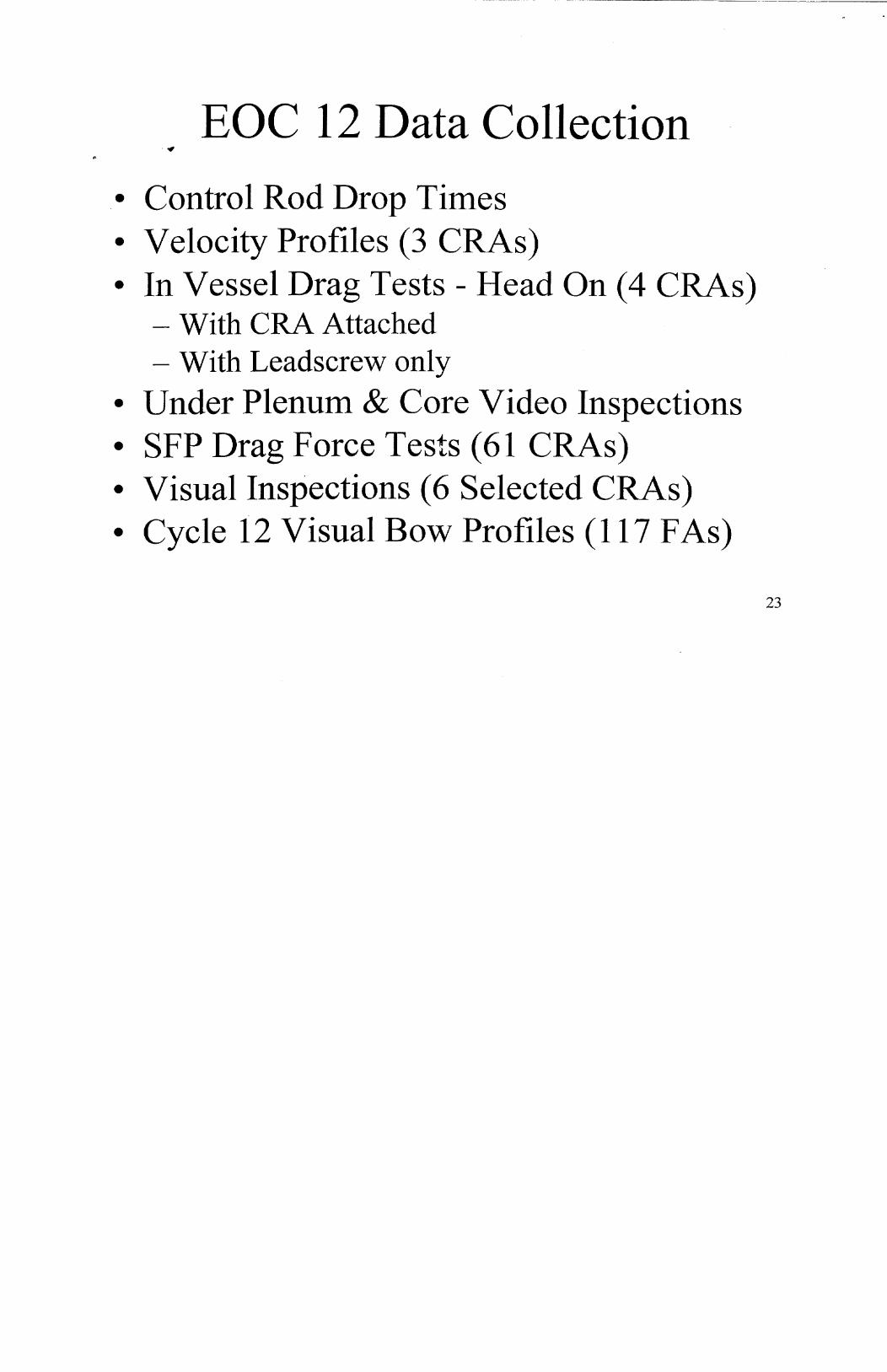
EOC 12 Data Collection
° Control Rod Drop Times * Velocity Profiles (3 CRAs) * In Vessel Drag Tests - Head On (4 CRAs)
- With CRA Attached - With Leadscrew only
* Under Plenum & Core Video Inspections * SFP Drag Force Tests (61 CRAs) * Visual Inspections (6 Selected CRAs) * Cycle 12 Visual Bow Profiles (117 FAs)
23

PIE Data Collection
"* Guide Tube (GT) Plug Gauge
"° GT Oxide Measurements
"° Fuel Assembly (FA) Growth
"° FA Bow (6 Assemblies)
"* F A Spacer Grid Oxide & Growth
"* Fael Rod Corrosion & Growth
"° Fuel Rod Diameter "° Spring Force Verification
24

EOC 12 Data Collection
25

As-Found Velocity Profiles Calculated Velocity for Retest of 9/11199
140.0
120.0
100.0
) 80.0
0 60.0
40.0
"---Rod 5-2, ( E-11
20.0 -- Rod 5-3, ( G-13)
-- Rod 2-2,(G-9)
0.0
0 20 40 60 80 100 120 140
Travel (inches)
26

SFP Drag Force Data CYCLE12DRAGFORCE
2 3 4 5 6 7 8 9 10 11 12 13 14 15
70
60
-. PliSi90 APS-
50
50
APS 50 AP S
* I
>130
A
B
C
D
E
F
G
HY
K
L
M
N
0
R
15
110
F APS 103 90 APSR
G 50 90 118 50
H 70 90
K 70 70 70
L Ps 48 APSR
5.
SLOWER
70 70
10 11 12 13 14
27
A•
Bi
Di
Ei
MI
S Pi
* Ri
IL2 3
i i i i i i i r-----i
1 1 i i i i -- i i - i i .- i i i
i i i i i p i i i i --i
APS 90 JAPS
W
[APS 50 APSI
'd
'T~
- LL -- _--L _
~ 1 -T 1 :; 1 T
IA -1
FI-T
LLFfL
sI 17I LI z 1 01 6 8 L 9 s f
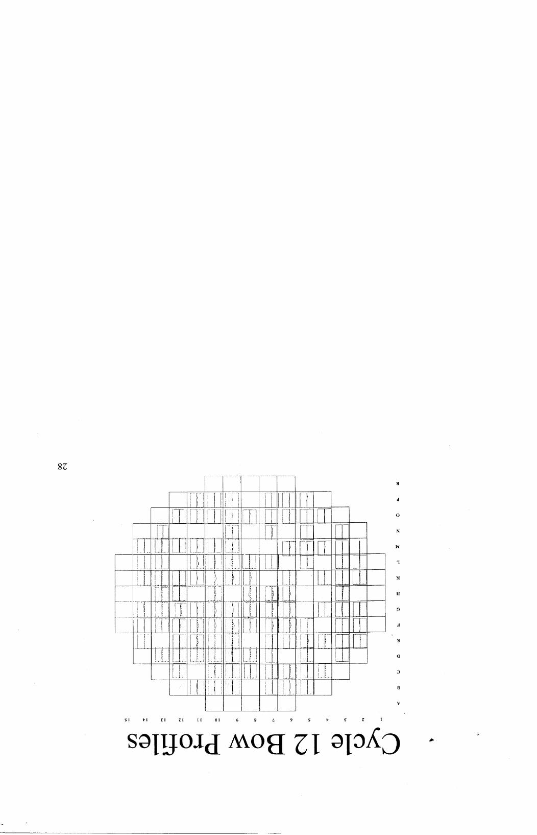
SOIIJO21d MOH Z I ;jOXj

IRI Fuel Assembly Bow Bundle 07UG Bow -. -.-- Cycle 11
Cycle 11 & Cycle 12 .Cycle 12'
IV
-10 -8 -6
0: -4 -2
-20
-40
°
-80
-160
2 4 6 8 10
29
Core Location E-IlI in Cycle 12
i.

Core Location M-05 Bow Cycle 12 M5 Bundle Bow
30
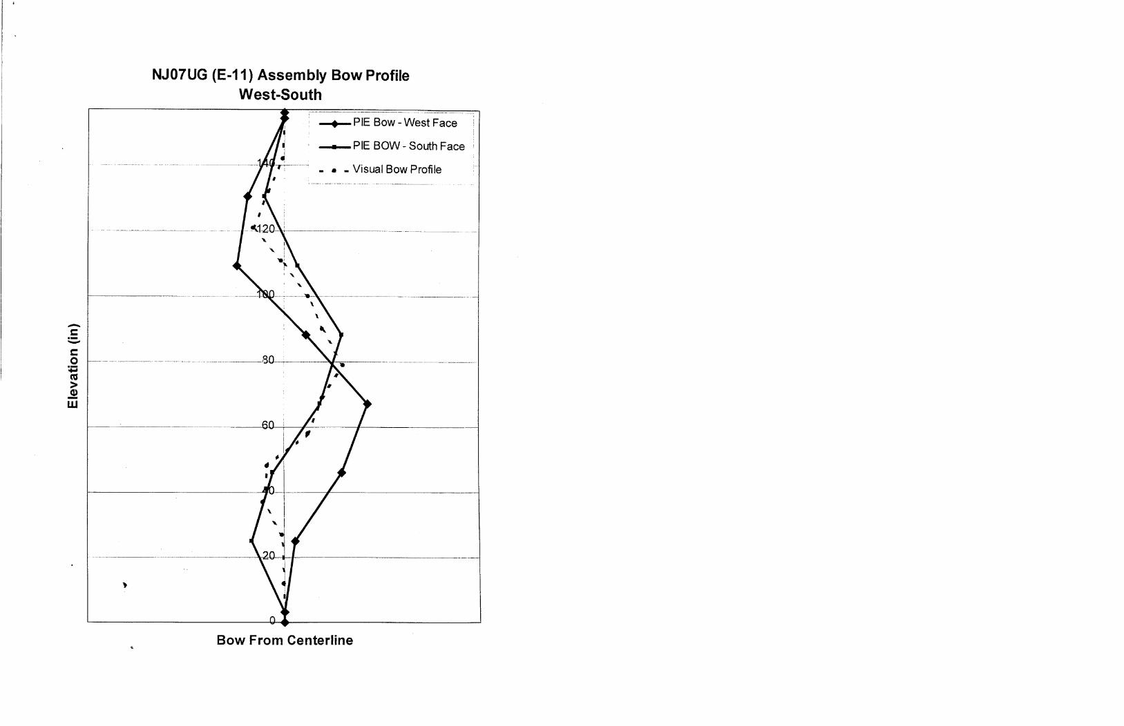
NJ07UG (E-1 1) Assembly Bow Profile West-South
Bow From Centerline
0
(U

PIE Data Collection
FCF -- David Mitchell
31

FCF Fuel Surveillance
* FCF response to NRC Proposed Bulletin 96-01 Supplement - Periodic post irradiation exams (PIEs) to evaluate fuel
performance control rod insertability
• FCF has added new inspections since 1997 to provide data for evaluation of IRI potential:
- CRA Drag Force
- Guide Tube Oxide
- Spacer Grid Width
- Spacer Grid Oxide32

CCD
a CD
r-
4
-t
C)
0 0
0
-- I I i - t ...... .. . . . - •. . .• •
S......... .. ... ..... . . ... ..... ..... ..... ..... .. .. ........ .... ........ .... .. ... .. _> _
, ..... • .............. i ~ ~ ~ ~.................... ........ . ... . .. ..... S. .. . . ... . . . . . .. . . . . . .. .. ... ... :... ...... ..--- ---
S.. . . .. . . . .. .... ... . . .. ... .. .. . . .. .... ... . . .. ----- --
if
S. .. .............. .. ... ... .. ...... ......
© i~ ~iO : ........ . .... ... .. ......9 .
COD
S. . ......................
C C
cn*
(n
(j)
C)
O�.
�i1
0
0
0

Summary of FCF Fuel Exams Conducted Prior to TMI Cycle 12
Fuel Exams prior to TMI Cycle 12 confirmed BWOG's 1997 response
- Linear fuel assembly growth with burnup
- No increase of bow magnitude with burnup
- Coupled fuel rod and fuel assembly growth
- Guide tube/thimble corrosion within design limits
- Limited increase in drag with burnup -- drag work too small to significantly increase drop times

TMI Cycle 12 Fuel Inspections
"* Hi-Res Visual
"* Fuel assembly length
"° Guide tube plug gauging
"* Guide tube oxide
thickness
"* Holddown spring force-
deflection
"• Spacer grid width
"• Spacer grid oxide
thickness
"• Fuel rod length - shoulder
gap
"* Fuel rod oxide thickness
0 Fuel rod diameter

TMI Cycle 12 PIE Data General Observations
* Fuel in Cycle 12 performed within design limits
° Compared to previous TMI cycles, Cycle 12 (IRI affected & non-affected FA's) experienced: - Higher fuel assembly growth - Higher fuel rod corrosion - Within design limits
° Hold down springs performed as designed

TMI Cycle 12 PIE Data IRI Evaluation
° IRI correlates to: - Complex fuel assembly bow
- Guide tube distortion (by plug gauging)
° IRI does not correlate to: - Fuel assembly growth
- Guide tube corrosion
- Spacer grid corrosion
- Fuel rod corrosion
° Highest growth assembly did not experience IRI

Fuel Assembly Bow Fuel Assembly Bow Profiles
Solid line- South Face. Dotted Line West Face. Triangle Plug Gage Depth
Bow by Assembly
FA Bow by Cycle 12 Core Location38
180
xi'
60
140
20
00
80
60
40
20
J 0
Summary of PIE Data Results
° Cause of IRI is excessive guide tube deformation
* While fuel assemblies in Cycle 12 had higher fuel
assembly growth and higher fuel rod oxide
thickness than previously observed at TMI, these
factors did not directly correlate with IRI

Guide Tube Deformation Conclusions
Guide tube deformation is correlated to
- A specific core region for more than one cycle
* Excessive guide tube deformation is not directly
or solely caused by
- Burnup
- Fast fluence
- Residence time
40

Framatome-France Experience with-Incomplete Rod Insertion
Framatome -- Etienne Morel
41

Ringhals "* In 1994 and 1995 Framatome observed slow rod drop
and incomplete rod insertion (IRI) in Ringhals 3 and 4
(12-foot 17x17) "* Similar design as Wolf Creek
"* Fueled with Framatome AFA-2G - Raised fuel rods
- Dashpot GT
- Low coolant flow
- High holddown spring force
"° IRI for assembly burnup between 34 and 42 GWd/t
"* Cycle length was 1 year
42

Framatome-Ringhals Experience With IRI
° The cause was determined to be GT
deformation
° S-shaped deformation was
excessive binding with the
determined to cause
CRA during
insertion
* Excessive FA compression contributed to GT
deformation
43
w.

Framatome Solutions for IRI
* Reduced holddown spring force - on-site yielding in 1995
- since, optimized holddown load
* Reinforcement of the dashpot zone (MONOBLOC TM guide thimble)
"• Increasing the stiffness of the GT by increasing the GT thickness and width
"• Low growth, low corrosion material for the GT (M5TM alloy)
45
Results of Actions V Implemented at Ringhals
"° Level of core-wide GT deformation is
reduced
"* This was verified by a significant number of
measurements
"* Rod drop time evolution has been reduced to
typical values
46

Improvements in FA Deformation at Ringhals
Lm 0 U
0
7F
Incormplete Rod Insertion
1994
Spring Setting, Reduced Number of Spring Leaves
1995 1996
Strengthen Dashpot
1997
New Guide Tube Design
1998
New Upper End Fitting Design
1999
47
I
0
402
0
E x
ft
Framatome Conclusions
• GT deformation measurements correlate with CRA
drop time
* GT deformation strongly depends on core location
* GT global deformation is not a strong effect of
assembly burnup
* Local deformation effects are observed primarily in
the dashpot and depend on burnup
48
Short Term Corrective Actions
"* Redesign Cycle 13 Core
"• Reduce Holddown Spring Force
49

Short Term Corrective Action Redesign Cycle 13 Core
Cycle 12 Cycle 13 RedesignA
B
C
E
F
G
H
15
A7Vr-T77B
C
D
E
F
G
H
8 9 10 11
Arrows illustrate same-quadrant shuffle12 13 14 15
50

Cycle 13 Shutdown Margin Sensitivity Studies
"* As Designed with Most Reactive Rod Stuck Out: 1 1.8%
"* Fzur Highest Drag CRAs, 30% Out with Most Reactive Rod Stuck Out: * 1.7%
", Conservative Case with 9 Rods near the Center of the Core at 30% Out and Most Reactive Rod Stuck Out: * 1.0%
"- Technical Specification requirement: * 1.0% 51
S-hort Term Corrective Actions
Reduce Holddown Spring Force
FCF -- Gary Williams
52

Hoiddown Spring Force Reduction
Objective
- To reduce holddown force on fuel assembly structure while maintaining spring performance
* Sufficient holddown to prevent lift
• Spring structural/material margins maintained
o Spring/control component interfaces maintained
* Reduction in loads are expected to mitigate FA/guide
tube distortion for TMI- 1 Cycles 13 and 14
53
Hoiddown Spring Set
° Spring Set Operation Prior to Cycle 13
- Deflection limited to control magnitude of plastic set
- Discharged and first bum assemblies used for benchmark to existing spring and fuel assembly data prior to operation
"• Load-deflection characteristics shown to be within design
"• Assembly growth verified
* Preload force verification
54

Hoiddown Spring Set
* All First Bum Assemblies with CRAs
- 8.5% Hot BOC 2 Load Reduction
- Deflection limited to EOC 2 cold shutdown deflection
* 46 Fresh Fuel Assemblies with BPRAs
- 21% Hot BOL Load Reduction
- Deflection limited to EOC 1 cold shutdown deflection
55

Hoiddown Spring Force Reduction Normalized Holddown Spring Loads
1.6 No Third Cycle Fuel Under CRA
1.5 MK-B.Spring..LocatedonlPenphery. MK-B Spring
1.4
o 1.3 .
"7 1.2 . . . .. .-
0 o Modified First Burn Fuel
0 " 0.9 NVlodified Fresh Fuel = 0.8
o 0.7 Z "-a .0.6 0 Mark-B Net Hydraulic
0-L------- ift
0.3 Ann00 80 1000 1200 1400 1600
Days
56

'V BOC 13 Baseline Data
* Control Rod Drop Times Acceptable
* Drag Data Acceptable
57

BOC 13 Data Collection
Tech Spec Control Rod Drop Time Testing
o In Vessel Drag Tests - Head'On (33 CRAs)
* Control Rod Velocity Profiles
* Reload Video Examinations:
- Lower Grid Plate
- FA Verifications58
I

Control Rod Drop Times in Fresh.Fuel
3.5
3
2.5
2
1.5
1
0.5
0
59
U, *0 0
0 I
0) .0 E z
Trip Time (seconds)

Control Rod Drop Times in Once Burned Fuel
0 12R As left
N 13R As left
Time (seconds)
4"ý llý -o
wV
25
20
"V 0 40 1n
Z
15
10
5
0
' 7IiIIILCo
'V 'V
Trip
60
I I ...... - -- . ,I I I RI I I i I

As-Left Velocity Profiles Velocity Profile -13 R As left
4 U. ~j
%.~0% 44m 0 4 0NU
"0
140
120
100
80
60
40
m Rod 5-3, (G13) o Rod 2-2, (G-9)
40 60 80 100 120
I
140
Travel (inches )
61
"o -0
O0
00
0 0
o
0)0
0
20
00 20
c
LL-t ,

C-4~ .. ... ... .
(II(2
'4
I
U, 0. 4
1 2:,
CIA
X1tI -
(D
Smi .o) 0 WuS.. ... ... . ..... ... ... ... ...... ............ .... .. ... ................. .. . . .... .. .... . ..... ............. ...
- I i
0.
0. ... !. . .
Co
In 11
0.l'•, 0. •
III
'4 ~IO 0 ~Ii LI. CD I -J �I z� 0 0-
(.4
0. 0.
. r i 4 - 4 P i ,-t-i i- 4
0
! " • i 0 IL
v I F i i I i !--
.. I .- -1 - -fLL ; CD

Future Analysis and Method Development for IRI
FCF -- Bernie Copsey
63
If Future IRI Activities
o Analyze CRA drop and drag data
* Benchmark Framatome-developed
analysis tools
* Product development
64

Analytical Method Development "* Single Fuel Assembly Deformation Model
- evaluate FA deformation as a function of spring loads, material properties, temperature, etc.
"* Core-Wide Fuel Assembly Deformation Model
- evaluate core-wide deformation as a function of FA characteristics
"* Guide Tube Drag Model - cvaluate CRA drag as a function of GT deformation
"* CF-A Drop Model *a-.valuate CRA drop time as a function of CRA drag
65

Product Development Long-term Plans on Mark-B Product Development:
° Refine hydraulic lift calculations to more realistically model in-core conditions
• Reduce spring force for Mark-B 10 design
• Develop fuel shuffle guidelines to minimize IRI
* Low-growth M5TM alloy66

Summary and Cycle 13 Actions
GPUN -- P. Walsh
67

Summary "* A significant amount of data has been collected, analyses
performed and actions taken to provide an understanding of the TMI - IRI event.
"• The plant operated within design basis in Cycle 12. "* Improvements were made to the Cycle 13 core:
- Core redesign to minimize same quadrant residence.
- Spring force reduction to minimize FA distortion. "• Startup data has shown acceptable control rod drop times
and drag forces. • Based on the corrective actions, continuous operation is
justified for Cycle 13.
68

B&WOG Response
* The B&WOG is closely following this event * rf ie Steering Committee has met and assigned a task to the
C PC to oversee the progress of FCF and determine the g,,.neric implications of the TMI event.
* The Core Performance Committee has met by conference call several times to exchange data and discuss with FCF
* The Data from the Crystal River 3 and Oconee 2 outages will be available to be discussed in early December.
* The B&WOG will schedule a meeting in that time frame with the NRC
70