co-cycle in cement and concrete : part 7: models for co
TRANSCRIPT

LUND UNIVERSITY
PO Box 117221 00 Lund+46 46-222 00 00
CO-cycle in cement and concrete : Part 7: Models for CO-absorption. Status, January2009
Nilsson, Lars-Olof; Fridh, Katja
2009
Link to publication
Citation for published version (APA):Nilsson, L-O., & Fridh, K. (2009). CO₂-cycle in cement and concrete : Part 7: Models for CO₂-absorption. Status,January 2009. (Report TVBM (Intern 7000 -rapport); Vol. 7200). Division of Building Materials, LTH, LundUniversity.
Total number of authors:2
General rightsUnless other specific re-use rights are stated the following general rights apply:Copyright and moral rights for the publications made accessible in the public portal are retained by the authorsand/or other copyright owners and it is a condition of accessing publications that users recognise and abide by thelegal requirements associated with these rights. • Users may download and print one copy of any publication from the public portal for the purpose of private studyor research. • You may not further distribute the material or use it for any profit-making activity or commercial gain • You may freely distribute the URL identifying the publication in the public portal
Read more about Creative commons licenses: https://creativecommons.org/licenses/Take down policyIf you believe that this document breaches copyright please contact us providing details, and we will removeaccess to the work immediately and investigate your claim.

CO2-cycle in cement and concrete Part 7: Models for CO2-absorption. Status, January 2009 Lars-‐Olof Nilsson & Katja Fridh Funded by the Swedish Consortium for Financing Basic Research in the Concrete Field
LUND INSTITUTE OF TECHNOLOGY LUND UNIVERSITY
Division of Building Materials
Report TVBM-‐7200 Lund 2009

ISRN LUTVDG/TVBM--09/7200--SE(1-11) ISSN 0348-7911 TVBM Lund Institute of Technology Telephone: 46-46-2227415 Division of Building Materials Telefax: 46-46-2224427 Box 118 www.byggnadsmaterial.lth.se SE-221 00 Lund, Sweden

2
List of contents
Background ................................................................................................................................ 3 Model for CO2-uptake during service ........................................................................................ 4
Assumptions/simplifications .................................................................................................. 4 Model for depth of carbonation.............................................................................................. 5 Model for CO2-uptake............................................................................................................ 7
Model for CO2-uptake of crushed concrete................................................................................ 9 References ................................................................................................................................ 11

3
Background In a previous project, funded by the Nordic Innovation Centre, CO2-uptake during the concrete life-cycle was studied, with project participants from Denmark, Iceland, Norway and Sweden. The objective was to provide documentation of concrete carbonation during the service life and recycling and re-use. The project resulted in a number of reports. Preliminary results indicated significant effects: “In countries with the most favourable recycling practice it is realistic to assume that 86 % of the concrete is carbonated after 100 years, taking up approximately 57 % of the CO2 emitted during the calcining process. Examples of impact of CO2 uptake in life cycle screenings show that 70-80 % of the potential CO2 uptake has been absorbed within 100 years lifetime after demolition and crushing”, Glavind (2006). The project had a limited budget and the analysis was based on a number of assumptions and uncertainties. The need for further work was identified. One weakness in the previous project was the simple square-root of time models used for carbonation and the lack of models for carbonation of crushed concrete. One part of the present project, part 7, concerns the development of new models for CO2-uptake. The project is funded by the Swedish Consortium for Financing Basic Research in the Concrete Field. The consortium members are: Cementa, Färdig Betong, Abetong, Swerock, Betongindustri and Strängbetong.

4
Model for CO2-uptake during service
Assumptions/simplifications In a previous report current models for carbonation were described. For the choice of model(s) for predicting CO2-uptake by carbonation, these assumptions/simplifications seem to be reasonable
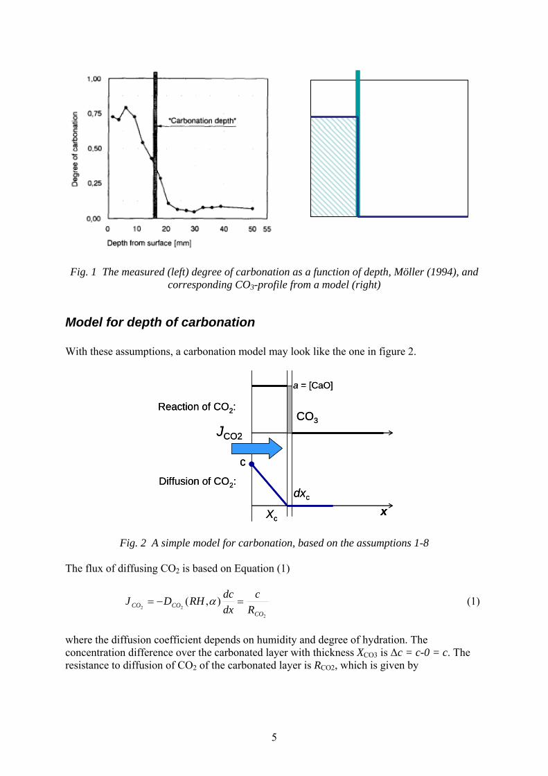
1. Carbonation is modelled as a sharp carbonation front moving inwards, cf. figure 1. 2. The movement of the carbonation front is due to the combined effect of CO2
diffusing through the already carbonated layer and CO2 being bound by the carbonation reaction at the depth of the front.
3. The amount of CO2 bound per volume of concrete must be quantified in the model. 4. The amount of CO2 bound per weight of binder may not be a constant for a
particular binder; possible effects of degree of hydration and moisture level should be part of a model and separately quantified.
5. The concrete is modelled as being homogenous, i.e. the higher binder content close to the exposed surface is neglected. This assumption is on the “safe” side, but could be too much on the “safe” side for crushed concrete where individual particles possibly are significantly heterogeneous, with most of the binder as a “shell” around larger aggregate grains.
6. All CaO is assumed to be fixed in position, i.e. no movement of Ca2+ and OH--ions is considered.
7. The CO2-binding capacity of carbonated concrete is set to be equal to 0, i.e. the diffusion of CO2 could be modelled as a steady-state transport process.
8. The diffusion coefficient for CO2 for a particular concrete should be modelled as a function of degree of hydration and moisture level.
9. The liberation of water from the carbonation reaction is neglected, i.e. does not increase the moisture content and humidity.
10. The effect of a surface treatment, paint, wall paper etc., must be considered, at least as an additional resistance to diffusion of carbon dioxide.
Theses assumptions/simplifications should be agreed upon, within the project. The consequences of these assumptions are several:
a) The CO2-uptake is quantified by models that include assumptions that are well known and frequently used in models for carbonation.
b) The historic moisture profiles of the concrete structure must be estimated, not only the equilibrium conditions; the effect of outdoor humidity variations and rain periods, and the early drying of excess moisture, must be considered to some extent.
c) The profiles of degree of hydration, originating from the time required for the early drying of the surface regions of the concrete structure, must be considered to some extent.
d) The significance of these effects should be smaller and smaller with time, i.e. with larger depths of carbonation.
5
Fig. 1 The measured (left) degree of carbonation as a function of depth, Möller (1994), and corresponding CO3-profile from a model (right)
Model for depth of carbonation With these assumptions, a carbonation model may look like the one in figure 2.
JCO2
CO3
Xc
dxc
a = [CaO]
cDiffusion of CO2:
Reaction of CO2:
x
JCO2
CO3
Xc
dxc
a = [CaO]
cDiffusion of CO2:
Reaction of CO2:
x
Fig. 2 A simple model for carbonation, based on the assumptions 1-8
The flux of diffusing CO2 is based on Equation (1)
2
22),(
COCOCO R
cdxdcRHDJ =−= α (1)
where the diffusion coefficient depends on humidity and degree of hydration. The concentration difference over the carbonated layer with thickness XCO3 is Δc = c-0 = c. The resistance to diffusion of CO2 of the carbonated layer is RCO2, which is given by

6
( )∫=
==
3
2
2 0 )(),(COXx
xCO
CO xxRHDdxR
α (2)
The amount of CO2 required to carbonate a unit volume of concrete is
( )CaO
COCO
MM
xCaO
CaOC
CaOCxa 23 )()( ⋅⋅⋅= [kg CO2/m3] (3)
where C is the cement content, CaO/C is the amount of CaO per weight of cement, (CaO)CO3/CaO is the degree of carbonation and M is the molar weight. a(x) is marked as being dependent on the depth x, since the degree of carbonation may be different at different depths. In the model in figure 2 the mass balance equation of CO2 at the depth of carbonation XCO3 will be
332)( COCOCO dXXadtJ ⋅=⋅ [kg CO2/m2] (4)
where dt is a short time step [s] during which the carbonation front advances dXCO3 [m]. This can also be written
)()(323
23
COCOCO
COCO
XaRc
XaJ
dtdX
⋅== (5)
After integration, the depth of carbonation is
( )∫
∫∫
=
= =
=
=
=⋅
==tt
t Xx
xCO
CO
Xx
x COCOCO
CO
xxRHDdxtXa
cdXX'
0'
0
0 3
2
3
3
33
)(),())((
α
(6)
The “problem” with this model is that the XCO3 appears on both sides of the equality sign! Consequently, the equation must be solved numerically, by dividing the carbonated layer into small slices with a thickness of dx and by taking small time-steps dt. During each time-step, the moisture distribution RH(x) must be known. If further assumptions are made, the model will of course become much more simple. If the humidity RH, the degree of hydration α and the amount a of CO2 required to carbonate a unit volume of concrete are assumed to be constant throughout the carbonated layer, the depth of carbonation will be
n
CO
COCO t
ttRHa
cRHDX ⎟
⎠⎞
⎜⎝⎛⋅⋅
⋅= 0
)()(2
2
2
3 (7)
where the exponent n depends on the humidity conditions and can be quantified from exposure data.

7
Most of the parameters in this model are possible to quantify, theoretically and from field measurements. The a-value has already been shown to include only one uncertain parameter, the degree of carbonation, that has to be measured for a set of typical binders and humidity conditions. The diffusion coefficient could be quantified together with the a-value by equation (7) in cases where the exponent n = 0. Alternatively, the diffusion coefficient could be estimated from an equation, derived for old German cement, Wierig (1964)
( )5105.4 )(12
xRHCBDCO −⋅⋅⋅= ε (8) where C is the cement content, ε is the capillary porosity, B is a constant and the parenthesis gives the humidity dependency.
0.0
0.1
0.2
0.3
0.4
0.5
0.6
0.7
0.8
0 0.01 0.02 0.03 0.04 0.05 0.06 0.07
Djup [m]
alfa
, α
0
2
4
6
8
10
12
14
16
0 0.01 0.02 0.03 0.04 0.05 0.06 0.07
Djup [m]
D c [*
1E-9
m2 /s
]
Model for CO2-uptake The CO2-uptake of a unit area of concrete will be

8
∫=
=⋅⋅=
3
32 0)(COXx
xCOCO dxxaXm [kg CO2/m2] (9)
or, if a is assumed to constant throughout the carbonated layer, simply
aXm COCO ⋅=32
[kg CO2/m2] (10) This model should be possible to set up in an Excel sheet and include all the parameter variations mentioned above.

9
Model for CO2-uptake of crushed concrete With the same assumptions as for carbonation during service, carbonation of crushed concrete could be modelled in a simple way. The difference is mainly the diffusion or convection of CO2 in the hollow space between the grains. Depending on the movement of air and the depth from the surface of the lump of grains, the consumption of CO2 by the grain surfaces may decrease the concentration of CO2 in the air in the hollow space. Consequently, that concentration must be included in the model as a variable.
dhollow
dgrain
Diffusion/convection in hollow space
Diffusion in to the CO3-front in the grains
dhollow
dgrain
Diffusion/convection in hollow space
Diffusion in to the CO3-front in the grains
Fig. 3 The carbonation process, in principle, for crushed concrete This process could be simplified into the simple model in figure 4.
dhollow
dgrains
dx
q qg
g
c1 c2
dhollow
dgrains
dx
q qg
g
c1 c2
Fig. 4 A possible, simple model for the rapid carbonation process for crushed concrete

10
The model consists of these parts 1. A constant air flow Q [m3/(m2 s)] between the grains. 2. Convection of CO2 with that air flow. 3. A concentration c(x) of CO2 as a function of depth from the surface of the lump of
concrete grains. 4. Diffusion of CO2 in that air, from a concentration gradient in the air. 5. A concentration c(xi) of CO2 at the surface of a concrete grain at a depth of xi. 6. Carbonation of the concrete grain i, in the same way as described above. 7. The humidity RH at different depths x from the outer surface must be modelled. If the
carbonation is very rapid, the liberation of water from the carbonation reaction may have to be included.

11
References CEB (1997): New Approach to Durability Design, CEB Bulletin No 238, Lausanne Möller, J. (1994) Measurement of carbonation in cement-based materials. Chalmers University of Technology, Göteborg, Licentiate thesis March 1994 Nilsson, L.-O. & Rodhe, M. (1997a) Micro-level Design, Sections 4.4.1- 4.4.6 of New Approach to Durability Design, CEB Bulletin No 238, Lausanne Nilsson, L.-O. & Rodhe, M. (1997b) The CTH Carbonation Model - A Micro-level Model for Carbonation in a Natural Climate. Appendix 2 of New Approach to Durability Design, CEB Bulletin No 238 Nilsson, L:-O. (2004): Service-life of the New Årsta Bridge. Effect of curing, cover and salt. Internal report In Swedish), Swetec, Markaryd Wierig, H.-J. (1984). Long-time studies on the carbonation under normal outdoor exposure. Proceedings of RILEM Seminar on the Durability of Concrete Structures Under Normal Outdoor Exposure, Hannover March 1984.