co capture technologies and opportunities in canada · co2 capture technologies and opportunities...
TRANSCRIPT

CO2 Capture Technologies and Opportunities in Canada
“Strawman Document for CO2 capture and Storage (CC&S) Technology Roadmap”
Murlidhar Gupta, Irene Coyle and Kelly Thambimuthu CANMET Energy Technology Centre
Natural Resources Canada
1st Canadian CC&S Technology Roadmap Workshop, 18-19 September 2003, Calgary, Alberta, Canada
1

Contents 1. Introduction 2. CO2 emission profile in Canada 3. How to capture CO2 4. Types of CO2 capture technologies
4.1 Chemical/physical absorption 4.1.1 Chemical absorption
4.1.1.1 Organic solvents 4.1.1.1.1 Amines
4.1.1.1.2 Sterically hindered amines 4.1.1.2 Inorganic solvents
4.1.1.2.1 Ammonia 4.1.2 Physical absorption 4.1.3 Hybrid absorption processes
4.2 Adsorption 4.3 Cryogenic 4.4 Membranes
4.4.1 Gas separation membranes 4.4.2 Gas absorption membranes 5. CO2 capture opportunities in Canada 5.1 Electricity generation
5.1.1 Post combustion capture 5.1.2 Pre-combustion capture 5.1.3 Oxy-fuel combustion
5.1.3.1 Novel oxyfuel capture concepts 5.1.3.1.1 MATIANT cycle 5.1.3.1.2 Graz cycle 5.1.3.1.3 Chemical looping combustion
5.2 CO2 capture opportunities in non-power sector 5.2.1 Iron and steel production 5.2.2 Cement production 5.2.3 Hydrogen/Ammonia production 5.2.4 Natural gas processing 5.2.5 Oil refining
5.3 CO2 capture costs: by sector 6. Future trends References
2

1. Introduction Currently 90% of the world’s primary energy requirement is supplied by fossil fuels, causing rising emissions of greenhouse gases (GHGs) and related concerns over global warming and climate change. CO2 is by far the most important of the GHGs, being responsible for about 64% of the enhanced greenhouse effect. As a result of anthropogenic CO2 emissions, atmospheric concentrations have risen by 30% from pre-industrial levels of 280 ppm to 360 ppm today, primarily as a consequence of fossil fuel use. However, at the current state of development, and the levels of risks and cost of non-fossil energy alternatives such as nuclear, biomass, solar energy, etc., these energy sources cannot meet our need for energy fed by fossil fuels. Additionally, any rapid change to non-fossil energy sources, even if it were possible, would result in large disruptions to the existing energy supply infrastructure with substantial consequences to the global economy. Some may argue that hydrogen could be a substitute for fossil energy. But it should be noted that currently most of the hydrogen produced commercially originates from fossil fuels. Per unit of heat generated, more CO2 is generated by producing H2 from fossil fuels than by directly burning those fossil fuels. Emission-free H2 production by water electrolysis, powered by renewable or nuclear sources is as yet not cost-effective (Hoffert et al., 2002). Given their inherent advantages such as availability, competitiveness and ease of transport, fossil fuels, which account for 80% of Canada’s primary energy demand (96% in Alberta and Saskatchewan-see Figure 1), are expected to remain a major component of Canada’s energy supply in the near future (CEO, 1999).
Figure 1: Sources of primary energy in the World and Canada Figure 2 shows the rising gap between Canada’s Kyoto target and Business as usual scenario (BAU). It is estimated that in the Kyoto compliance period (2008-2012), this gap will increase to the tune of 240 Mt of CO2 equivalent (Pearson, 2003). Through ratification of the Kyoto Protocol, the Government of Canada is committed to cap GHG emissions to an average of 6% below the 1990 level. The immediate he challenge for Canada (in particular, Alberta and Saskatchewan) is to reduce CO2 emissions into the atmosphere while minimizing any associated
3
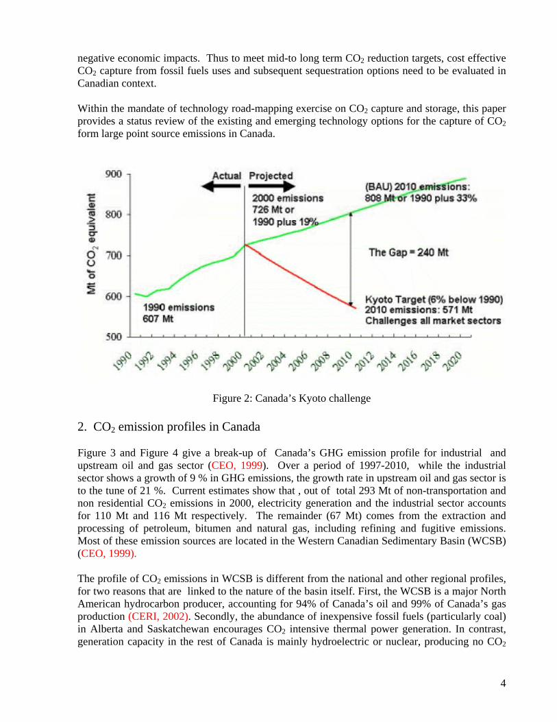
negative economic impacts. Thus to meet mid-to long term CO2 reduction targets, cost effective CO2 capture from fossil fuels uses and subsequent sequestration options need to be evaluated in Canadian context. Within the mandate of technology road-mapping exercise on CO2 capture and storage, this paper provides a status review of the existing and emerging technology options for the capture of CO2 form large point source emissions in Canada.
Figure 2: Canada’s Kyoto challenge 2. CO2 emission profiles in Canada Figure 3 and Figure 4 give a break-up of Canada’s GHG emission profile for industrial and upstream oil and gas sector (CEO, 1999). Over a period of 1997-2010, while the industrial sector shows a growth of 9 % in GHG emissions, the growth rate in upstream oil and gas sector is to the tune of 21 %. Current estimates show that , out of total 293 Mt of non-transportation and non residential CO2 emissions in 2000, electricity generation and the industrial sector accounts for 110 Mt and 116 Mt respectively. The remainder (67 Mt) comes from the extraction and processing of petroleum, bitumen and natural gas, including refining and fugitive emissions. Most of these emission sources are located in the Western Canadian Sedimentary Basin (WCSB) (CEO, 1999). The profile of CO2 emissions in WCSB is different from the national and other regional profiles, for two reasons that are linked to the nature of the basin itself. First, the WCSB is a major North American hydrocarbon producer, accounting for 94% of Canada’s oil and 99% of Canada’s gas production (CERI, 2002). Secondly, the abundance of inexpensive fossil fuels (particularly coal) in Alberta and Saskatchewan encourages CO2 intensive thermal power generation. In contrast, generation capacity in the rest of Canada is mainly hydroelectric or nuclear, producing no CO2
4

directly.
Figure 3: Canada’s emission profile : industrial sector (CEO, 1999)
Figure 4: Canada’s emission profile: upstream oil and gas sector (CEO, 1999)
5

3. How to capture CO2 The objective of CO2 capture is to produce a concentrated stream of CO2 which can be transported and sequestered underground or in deep oceans. The CO2 capture concept is not new to industry. The capture processes have been widely applied in the natural gas processing and chemical processing industries for over 60 years and existing practice is to vent it to atmosphere. The concept of capture for the purpose of sequestration, including the power generation sector is relatively new. Figure 5 gives an idea about CO2 capture pathways in a broad spectrum of fossil energy conversion processes including power generation.
Figure 5: CO2 capture pathways in fossil energy conversion processes In general CO2 capture can be divided into three categories: 3.1 Post-combustion capture: Capture of CO2 in the downstream of a carbonaceous fuel based combustion unit is referred as post-combustion capture process. Conventional process heaters and industrial utility boilers fit into this category. In these processes, the fossil fuels are combusted in excess air, resulting in a flue gas stream which contains lean concentrations of CO2 (12-15 v/v% for modern coal fired power plants and 4-8 v/v% for natural gas fired plants). In some of cases, such as cement kilns and blast furnaces where flue gases contain process related CO2 also, the CO2 concentration in the flue gases may vary from 14-33%. CO2 from the post combustion flue gases can be captured by a variety of techniques such as absorption by amines, membrane separation and cryogenic separation etc. Under the current state of technology, only absorption and to some extent membranes are considered to be economically viable technologies. These issues will be discussed further in Section 4 and section 5. 3.2 Oxy-fuel combustion:
6

CO2 capture method through oxy-fuel combustion is a variant of post combustion capture process. However removal of nitrogen from the air in the oxidant stream produces highly concentrated flue gas stream ( >80 v/v% CO2) which can be easily concentrated further through simple gas purification techniques such as cryogenic separations. Although the oxyfuel processes such as RILEE (Recycle Incineration Low Exhaust Emission) process that involves the oxy-fuel burners for treating non-ferrous scrap, have been widely applied, their application in process heaters, in large industrial utility boilers and gas turbines is relatively a new concept and will require comprehensive breakthroughs in terms of low cost oxygen production techniques and combustion in oxygen rich environment. Section 4 and section 5 will discuss these issues in further details. 3.3 Pre-combustion capture: The pre-combustion capture process is basically a de-carbonization of carbonaceous fuels. In this case, through gasification (controlled oxygen or air) or through steam reforming, the fuel is converted to carbon mono-oxide (CO) and hydrogen (fuel gas). Subsequently, CO is converted to CO2 through shift conversion process resulting a stream rich in CO2 and H2. The concentration of CO2 in this stream is around 25-40% and the total pressure is typically in the range of 2.5-5 MPa. Thus the partial pressure of CO2 in the pre-combustion capture is very high compared to post-combustion method, making it much easier to separate through techniques such as solvent scrubbing etc. 4. Types of CO2 capture technology Most CO2 capture technologies themselves are not new. Specialized chemical solvents were developed more than 60 years ago to remove CO2 from impure natural gas, and natural gas operations continue to use these solvents today. In addition, several power plants and other industrial plants use the same or similar solvents to recover CO2 from flue gases for application in the food processing and chemical industries. Finally, a variety of alternative methods are used to separate CO2 from gas mixtures during the production of hydrogen for petroleum refining, ammonia production and in other industries (Anderson and Newell, 2003). The selection of a technology for a given capture application depends on many factors i.e. partial pressure of CO2 in the gas stream, extent of CO2 recovery required, sensitivity to impurities, such as acid gases, particulates, purity of desired CO2 product, capital and operating costs of the process, the cost of additives necessary to overcome fouling and corrosion where applicable the environmental impacts (White et al., 2003). Based upon the method of CO2 removal, capture technologies can be broadly classified into the following categories (also see Figure 6):
1. Chemical/physical solvent scrubbing 2. Adsorption 3. Cryogenic 4. Membranes
7

Figure 6: Strawman of CO2 capture technologies 4.1 Chemical/physical absorption Chemical and or physical absorption processes are widely used in the petroleum, natural gas and chemical industries for separation of CO2. The solvent capacity of an absorbed gas is a function of its partial pressure in the absorption unit (Thambimuthu,1993; Kohl and Nielsen, 1997). In physical absorption, the solvent capacity or loading, which initially follows Henry’s law (for ideal non interacting gas mixtures), assumes an almost linear dependence on the gas partial pressure. In chemical absorption, the solvent loading assumes, a non-linear dependence on partial pressure and is higher at low partial pressures. At the concentrations approaching the saturation loading of the solvent, chemical absorption decreases sharply. Large increases in the partial pressure of the absorbed gas result in a very small increase in the solvent loading. This behaviour is caused by an effect akin to weak physical absorption and usually arises from gas absorption in the aqueous component of the solvent used in the process. Thus, the retention capacity of a chemical solvent in a chemical absorption process is much higher at low partial pressures, whereas the converse is true for physical absorption(Thambimuthu,1993). The primary method of regeneration in physical absorption occurs by a simple pressure reduction in the system. This method of regeneration reduces the operating costs. In chemical absorption, heating or reboiling is necessary for solvent regeneration and may be cost effective if the process has large supply of low cost and sufficiently high temperature heat or steam available to it. However with much higher chemical solvent loading capacities, the solvent circulation rates are much lower, with high capital cost savings. Table 1 lists the most common industrial CO2 scrubbing solvents and their process conditions. 4.1.1 Chemical Absorption:
8

The majority of chemical solvents are organic amine based. Stoichiometric manipulation of this group has lead to the development of sterically hindered amines, which enhances the absorption capacity of the solvent. Alternative inorganic solvent systems are Na/K carbonates and aqueous ammonia processes. Prior to CO2 removal the CO2 containing stream is cooled and particulates and other impurities are removed as far as possible. It is then passed into an absorption vessel where it comes into contact with the chemical solvent, which absorbs much of the CO2 by chemically reacting with it to form a loosely bound compound. The CO2 rich solvent from the bottom of the absorber is passed into another vessel (stripper column) where it is heated with steam to reverse the CO2 absorption reactions. CO2 released in the stripper is compressed for transport and storage and the CO2 free solvent is recycled to the absorption vessel. CO2 recovery rates of 98% can be achieved, and product purity can be in excess of 99% (Wilson, 1992). 4.1.1.1 Organic solvents 4.1.1.1.1 Amines Three classes of amines, basically primary, secondary and tertiary, are generally used as organic chemical solvents. Monoethanolamines (MEA) are more reactive than secondary amines and hence dominate the CO2 capture market (Thambimuthu, 1993). Amine scrubbing technology has been established for over 60 years in the chemical and oil industries, for removal of hydrogen sulphide and CO2 from gas streams. This experience is largely on natural gas streams and/or with chemically reducing (primarily oxygen deficient) gases but there are several facilities in which amines are used to capture CO2 from flue gas streams today, one example being the Warrior Run coal fired power station in the USA, where 150 t/d of CO2 is captured (Thambimuthu et al., 2002). The main concerns with MEA and other amine solvents are corrosion in the presence of O2 and other impurities, high solvent degradation rates from reaction with SO2 and NO2 and the large amounts of energy required for regeneration. As much as 80% of the total energy consumption in an alkanolamine absorption process occurs during solvent regeneration (White et. al, 2003). These factors generally contribute to large equipment, high solvent consumption and large energy losses. New or improved solvents with higher CO2 absorption capacities, faster CO2 absorption rates, high degradation resistance and low corrosiveness and energy use for regeneration are needed to reduce equipment sizes and capital and operating costs.
9
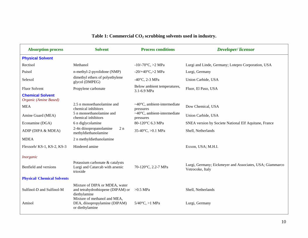
Table 1: Commercial CO2 scrubbing solvents used in industry.
Absorption process Solvent Process conditions Developer/ licensor
Physical Solvent
Rectisol Methanol -10/-70°C, >2 MPa Lurgi and Linde, Germany; Lotepro Corporation, USA
Puisol n-methyl-2-pyrolidone (NMP) -20/+40°C,>2 MPa Lurgi, Germany
Selexol dimethyl ethers of polyethylene glycol (DMPEG) -40°C, 2-3 MPa Union Carbide, USA
Fluor Solvent Propylene carbonate Below ambient temperatures, 3.1-6.9 MPa Fluor, El Paso, USA
Chemical Solvent Organic (Amine Based)
MEA 2.5 n monoethanolamine and chemical inhibitors
~40°C, ambient-intermediate pressures Dow Chemical, USA
Amine Guard (MEA) 5 n monoethanolamine and chemical inhibitors
~40°C, ambient-intermediate pressures Union Carbide, USA
Econamine (DGA) 6 n diglycolamine 80-120°C 6.3 MPa SNEA version by Societe National Elf Aquitane, France
ADIP (DIPA & MDEA) 2-4n diisopropanolamine 2 n methyldiethanolamine 35-40°C, >0.1 MPa Shell, Netherlands
MDEA 2 n methyldiethanolamine
Flexsorb/ KS-1, KS-2, KS-3 Hindered amine Exxon, USA; M.H.I.
Inorganic
Benfield and versions Potassium carbonate & catalysts Lurgi and Catarcab with arsenic trioxide
70-120°C, 2.2-7 MPa Lurgi, Germany; Eickmeyer and Associates, USA; Giammarco Vetrocoke, Italy
Physical/ Chemical Solvents
Sulfinol-D and Sulfinol-M Mixture of DIPA or MDEA, water and tetrahydrothiopene (DIPAM) or diethylamine
>0.5 MPa Shell, Netherlands
Amisol Mixture of methanol and MEA, DEA, diisopropylamine (DIPAM) or diethylamine
5/40°C, >1 MPa Lurgi, Germany
10

4.1.1.1.2 Sterically hindered amines Sterically hindered amines are amines in which a bulky alkyl group is attached on the amino group. As a consequence the reactivity is different from the alkalanolamines. Sterically hindered amines currently used in absorption processes are 2-amino-2-methyl-1-propanol (AMP), 1,8-pmethanediamine (MDA) and 2piperidine ethanol (PE). They were originally developed by Exon. (Veawab et al., 2002). The advantage of sterically hindered amines over alkanolamines is that only 1 mol of the sterically hindered amine, instead of 2 mol of alkanolamine, is required to react with 1 mol of CO2. Thermal degradation occurs at temperatures higher than 478 K. Sterically hindered amine systems can have lower heats of absorption/regeneraton as compared with MEA. This makes these types of amines potential candidates for CO2 removal in power generation systems. (White et. al, 2003) Another set of sterically hindered amines are KS-1. KS-1 has a lower circulation rate compared to MEA, (because of its higher lean to rich CO2 loading differential), lower regenerative temperature (383K), and lower heat of reaction with CO2. KS-1 has been used in a commercial gas scrubbing operation in Malaysia to produce a pure CO2 stream for urea production” (Mimura et al., 2000). 4.1.1.2 Inorganic solvents The non-organic based chemical solvents include potassium, sodium carbonate and aqueous ammonia. Among these, potassium carbonate has the dominant market share. The potassium carbonate process can be used in various configurations. Generally these process configurations are accompanied by minor changes in the solvent and catalytic additives used in the process. Overall the system uses an aqueous solution of about 20-40% wt% of the potassium salt. The absorption of CO2 shows an equilibrium behaviour that is favourable even at temperatures (typically 70-120oC) close to the atmospheric boiling point of the solvent. Consequently, it is possible to operate the process with a relatively low incremental heat input for solvent regeneration or gas desorption. This feature normally eliminates the use of the heat exchangers used to cool the solvent flow between the regenerator and absorption column. The popular Banfield process is a split flow version of the basic potassium carbonate process used at moderate gas pressures of around 2.2 MPa. 4.1.1.2.1 Ammonia Most recently ammonia has been tested as a sorbent for CO2. It has been observed that the maximum CO2 removal efficiency by NH3 absorbent can reach 99% and the CO2 loading capacity can approach 1.2 kg CO2 /kg NH3 (Yeh at al, 2002). On the other hand, the maximum CO2 removal efficiency and loading capacity by MEA absorbent were 94% and 0.40 kg CO2 /kg MEA (White et. al, 2003). At pH=11.0, when the total ammonium carbonate concentration is 0.1 M, ammonia equilibrium vapor pressure is 0.0034 atm, and CO2 removal efficiency is observed to be 100% from an initial 12% CO2 in flue gas (Huang and Chang, 2002).
11

However, the concerns with this technology include the highly volatile nature of ammonia. Also this technology lacks in the regeneration of ammonia from its carbonate salts (Huang and Chang, 2002). Capability of anion-exchange resins to regenerate ammonia from ammonium bicarbonate as well as the feasibility for the regeneration of resin by heated water and collection of CO2 are being tested. Released ammonia will react with the remaining ammonium bicarbonate to form ammonium carbonate, which results in the resin’s inability to completely regenerate ammonia. A new scrubbing system has been proposed where CO2 in flue gas, along with the acid gas pollutants, SO2, NOx, HCl and HF, could be removed in a regenerable scheme (Yeh at al, 2002). The key advantage to the process is that the thermal energy consumption for the CO2 regeneration is expected to be significantly less than the MEA process. (White et. al, 2003) The thermal energy requirement is approximately 50% less in a dual alkali system using ammonia to absorb CO2 and anion-exchange resins to regenerate ammonia for reuse than using amine to absorb CO2 and steam stripping to dissociate the resulting carbamates. (Huang and Chang, 2001). The major drawback of inorganic solvents lies in the fact that they may release Na, K and V in the product gas that could promote deposition, erosion and corrosion in gas turbines and fuel cells. Others such as arsenic trioxide are potent chemicals hazardous to plant and animal life.
4.1.2 Physical absorption The physical solvents are ideally suited for the removal of CO2 from fuel gases with high vapour pressure (mostly in reducing atmospheres). These physical solvents combine less strongly with CO2. The advantage of such solvents is that CO2 can be separated from them in the stripper mainly by reducing the pressure, resulting in much lower energy consumption. Table 1 gives an idea about the main physical solvents that could be used for CO2 capture (Thambimuthu, 1993). These are basically cold methanol (Rectisol process), dimethylether of polyethylene glycol (Selexol process), propylene carbonate (Fluor process) and n-methyl-2pyrollidone (NMP-purisol). Physical solvent scrubbing of CO2 is well established, e.g. in ammonia production plants. Majority of physical absorption solvents are based on organic solvents with high boiling points and low vapour pressures. Other than methanol, most of these solvents can be used at ambient temperatures without appreciable vaporization losses, but may require special water washing stages to mitigate solvent losses. In general, all physical solvents must have an equilibrium capacity for absorbing CO2 several times that of water and a lower capacity for removing other primary constituents of the gas stream. They must have low viscosity, low or moderate hygroscopicity, and low vapor pressure at ambient temperature. They must be non corrosive to common metals as well as non reactive with all components in the gas stream. (White et. al, 2003). The technology development needs for physical solvents are similar in principle to those for chemical solvents. In particular, there is a need for higher efficiency gas-liquid contactors and solvents with lower energy requirements for regeneration (Thambimuthu et al. 2002). 4.1.3 Hybrid absorption processes Hybrid absorption processes use solvents which offer a combination of chemical and physical absorption. Processes currently used with coal syngas for removal of CO2 and sulphur
12

compounds are the Shell Sufinol® process and Amisol® process developed by Lurgi (Collot, 2003). In its original form the shell Sufinol process uses sufolan (tetrahydroehiophene dioxide) as the organic solvent and an amine solvent, DIPA (di-isopropanolamine) with 15% water. Shell has also developed M-Sufinol® in which the amine solvent is MDEA instead of DIPA. The main difference between the sulfinol® unit and an alkanolamine unit is that sufinol® unit tolerates a much higher acid gas loading (twice as much as the standard MEA unit) before becoming corrosive (Collot, 2003). The Amisol® process is based on a mixture of methanol and either MEA or DEA as the chemical component and a small percentage of water. Another version which is particularly suited for the removal of large quantities of CO2 uses MDEA as the chemical solvent component. 4.2 Adsorption The intermolecular forces between gases such as CO2 and the surface of certain solid materials permit separation by adsorption. Selective adsorption of the gases depends on temperature, partial pressures, surface forces and adsorbent pore size. The solid adsorbents, such as activated carbon and molecular sieves are normally arranged as packed beds of spherical particles. The process operates on a repeated cycle with the basic steps being adsorption and regeneration. In the adsorption step, gas is fed to a bed of solids that adsorbs CO2 and allows the other gases to pass through. When a bed becomes fully loaded with CO2, the feed gas is switched to another clean adsorption bed and the fully loaded bed is regenerated to remove the CO2. In pressure swing adsorption (PSA), the adsorbent is regenerated by reducing pressure. In temperature swing adsorption (TSA), the adsorbent is regenerated by raising its temperature and in electric swing adsorption (ESA) regeneration takes place by passing a low-voltage electric current through the adsorbent. Both PSA and TSA are commercially available technologies and are used in commercial H2 production, bulk separation of O2 and in the removal of CO2 from natural gas (McKee, 2002). A combination process of pressure and temperature swing adsorption (PTSA) has been tested at the bench scale and pilot scale levels by Tokyo Electric Power Company (TEPCO) & Mitsubishi Heavy industries respectively (Smith, 1999). Bench scale PTSA tests selected an adsorbent zeolite Ca-X(ß) for having a high capacity and selectivity . Pilot-scale test from a power station burning coal/oil mix and a flue gas with a concentration of 10.8% CO2 generated a recovery of 90% CO2. Using PTSA compared to PSA reduced the power consumption required for separation by 11% (Smith, 1999) ESA which is commercially not ready, holds promise as a possible advanced CO2 separation technology that uses less energy than other processes. The material used in ESA for separation of CO2 is basically carbon fiber composite molecular sieve(CFCMS). The Oak Ridge National Laboratory in USA is developing a novel ESA process which adsorbs amongst the other gases CO2 from syngas from low hydrogen-to-carbon ratio fuels on a carbon fiber molecular sieve with a monolithic structure. After saturation of the carbon fibre adsorbent with CO2, immediate desorption of the adsorbed gas is accomplished by applying low voltage across the adsorbent. The efficacy of the ESA process for gas separation has been studied at pressures up to 2 MPa and temperatures up to 100oC. A CO2 uptake of 45% (wt) has been demonstrated at a pressure of 2 MPa and a temperature of 25oC (Klara and Srivastava, 2002; Collot, 2003).
13
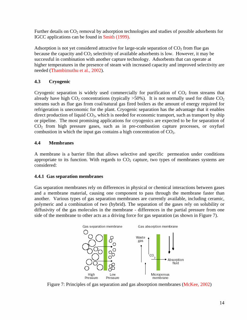
Further details on CO2 removal by adsorption technologies and studies of possible adsorbents for IGCC applications can be found in Smith (1999). Adsorption is not yet considered attractive for large-scale separation of CO2 from flue gas because the capacity and CO2 selectivity of available adsorbents is low. However, it may be successful in combination with another capture technology. Adsorbents that can operate at higher temperatures in the presence of steam with increased capacity and improved selectivity are needed (Thambimuthu et al., 2002). 4.3 Cryogenic Cryogenic separation is widely used commercially for purification of CO2 from streams that already have high CO2 concentrations (typically >50%). It is not normally used for dilute CO2 streams such as flue gas from coal/natural gas fired boilers as the amount of energy required for refrigeration is uneconomic for the plant. Cryogenic separation has the advantage that it enables direct production of liquid CO2, which is needed for economic transport, such as transport by ship or pipeline. The most promising applications for cryogenics are expected to be for separation of CO2 from high pressure gases, such as in pre-combustion capture processes, or oxyfuel combustion in which the input gas contains a high concentration of CO2. 4.4 Membranes A membrane is a barrier film that allows selective and specific permeation under conditions appropriate to its function. With regards to CO2 capture, two types of membranes systems are considered: 4.4.1 Gas separation membranes Gas separation membranes rely on differences in physical or chemical interactions between gases and a membrane material, causing one component to pass through the membrane faster than another. Various types of gas separation membranes are currently available, including ceramic, polymeric and a combination of two (hybrid). The separation of the gases rely on solubility or diffusivity of the gas molecules in the membrane - differences in the partial pressure from one side of the membrane to other acts as a driving force for gas separation (as shown in Figure 7).
Figure 7: Principles of gas separation and gas absorption membranes (McKee, 2002)
14

2.4.1 Gas absorption membranes Gas absorption membranes are micro-porous solid membranes that are used as contacting devices between gas flow and liquid flow. The CO2 diffuses through the membrane and is removed by the absorption liquid, which selectively removes certain components from a gas stream on the other side of the membrane. In contrast to gas separation membranes it is the absorption liquid (not the membrane) that gives the process its selectivity (McKee, 2002). Los Alamos National Laboratory is developing a high temperature polymeric membrane with better separation performance by supporting a polybenzimidazole (PBI) film on a sintered metal support. The PBI possesses excellent chemical resistance, a high glass transition temperature (450oC) and good mechanical strength. This type of membrane is highly selective and is able to operate at flue gas conditions (Klara and Srivastava, 2002).
Several membranes with different characteristics may be required to separate high-purity CO2. Membranes could be used to separate CO2 at various locations in power generation processes, for example from fuel gas in IGCC or during combustion in a gas turbine. However membranes have not been optimized for the large volume of gas separation that is required for CO2 capture. Membranes cannot usually achieve high degrees of separation, so multiple stages and/or recycle of one of the streams is necessary. This leads to increased complexity, energy consumption and costs. Much development is required before membranes could be used on a large scale for capture of CO2 in power stations. 5. CO2 capture opportunities in Canada Although the electricity generation, industrial sector and fossil fuel processing industry contributes to only 54% of total CO2 emissions during 2000, they are potential stationary sources, well suited for large scale CO2 capture and storage applications. Among them power plants are the clearest contenders. But the other energy intensive industries like oil and gas refining, hydrogen and ammonia processing, iron and steel manufacturing and cement production also combust large quantities of fossil fuels and have significant CO2 emissions. In addition to those combustion sources, some of these sectors produce non-combustion CO2 rich by-product process streams for which the incremental cost of capture and storage is very low. 5.1 Electricity Generation CO2 emissions from electric power generation in Canada have been estimated to be approximately 110 Mt CO2 /year which is 20% of Canada’s total CO2 emissions in 2000 (CEO, 1999). In order to meet Canada’s Kyoto commitments, it is anticipated that carbon capture might find an early application in Canadian electric power generation. As discussed in section 3, all three methods i.e. post-combustion capture, pre-combustion capture and oxyfuel combustion can be effectively applied in electricity sector. 4.1.1 Post-combustion capture Although, one can suggest to compress and store the flue gas underground but at the scale of power plants, the energy required for compression would be very large and more over the underground reservoirs would quickly become full. It is therefore necessary to separate the CO2 from the flue gas which contains a lion’s share of nitrogen.
15
As the CO2 partial pressure in flue gas is significantly low, the best proven technique for post combustion capture of CO2 at present is to scrub the flue gas with an amine solution in a chemical absorption process. The amine from the scrubber is heated by steam to release high purity CO2 and the CO2-free amine is then reused in the scrubber. However, some additional measures are needed to minimize contamination of the CO2 capture solvents by impurities in the power station flue gas, such as sulphur and nitrogen oxides. In many respects, post-combustion capture of CO2 in a power station is analogous to wet flue gas desulphurisation (FGD) techniques, which is widely used on coal and oil fired power stations to reduce emissions of SO2. Another advantage of post-combustion capture systems in power station is that they can operate in a plug and play mode with the existing fleet of pulverized coal power plants and natural gas fired plants without significant changes in the upstream systems. Under prevailing uncertainty in the regulatory norms, this gives tremendous flexibility to existing utilities operators. However, the low concentration of CO2 in power station flue gas means that a large volume of gas has to be handled, which results in large equipment sizes and high capital costs. A further disadvantage of the low CO2 concentration is that powerful chemical solvents have to be used to capture CO2 and regeneration of the solvents to release the CO2 requires a large amount of energy. If the CO2 concentration and pressure could be increased, the CO2 capture equipment would be much smaller and different physical solvents could be used, with lower energy penalties for regeneration. 4.1.2 Pre-combustion capture Energy or power generation processes where pre-combustion capture can be applied include IGCC (integrated gasification combined cycle) plants fuelled by coal, residual oil and petroleum coke, but these plants do not yet have long continuous operating times, causing concerns for reliability and availability. With the addition of CO2 capture, one of the novel aspects is that the fuel gas feed to the gas turbine is essentially hydrogen. The hydrogen will be diluted using nitrogen or steam to reduce emissions of nitrogen oxides from the gas turbine combustors. It is expected that it will be possible to burn hydrogen in an existing gas turbine with little modification, however this is not a demonstrated technology. Nevertheless there are a large number of existing IGCC plants such as in refineries where hydrogen rich fuels are used in the gas turbines. (Thambimuthu et al., 2002) 5.1.3 Oxy-fuel combustion If fuel is burnt in pure oxygen in an existing industrial boiler, the flame temperature is excessively high, so some CO2-rich flue gas would be recycled to the combustor to make the flame temperature similar to that in a normal air-blown combustor. The nitrogen-free combustion process can benefit from a highly reduced flue gas volume (around one fifth to one third) leaving as the exhaust stream from the process and is highly rich in CO2 with much lower flue gas treatment costs. For existing boilers, a retrofit technology involving partial flue gas recycle (FGR) may be considered. In this approach, nitrogen is basically replaced by CO2 and the boiler heat transfer profiles remain close to the existing air-fired process. On the other hand for new plants, the oxy-fuel combustion strategy would include advanced, compact boilers with low or zero flue gas recycle, resulting in significant reductions in the boiler dimensions and capital and operating costs.
16

The advantage of oxygen-blown combustion is that the flue gas has a CO2 concentration of above 80%, compared to 4-14% for air blown combustion, so only simple CO2 purification is required. Currently, the major energy and cost penalty in oxyfuel combustion arises from oxygen production in cryogenic air separation units. New technology development for oxygen production targets the commercial development of novel oxygen transport membranes (OTMs) for air separation, that may be available within the Kyoto compliance period of 2008-2012 (Miller, 2003). With the advent of commercial scale air separation modules based on OTMs, oxyfuel combustion is likely to be an attractive option for capturing CO2 in existing and new pulverized coal fired units.
Figure 8: A simple schematic diagram of combustion based power cycles with CO2 capture options
Figure 8 provides a generic picture of carbon capture in electricity generation. 5.1.3.1 Novel oxy-fuel capture concepts Unlike the oxy-fuel capture technique discussed above, few promising variants of oxy-fuel combustion are still in conceptual stages of development. These concepts also rely on the production of pure CO2 streams from fuel combustion, facilitating CO2 removal with minor purification of the gas stream. 5.1.3.1.1 MATIANT Cycles These power cycles are based on variations of the oxygen combustion approach. For example in the MATIANT cycle, CO2 produced from fuel combustion in oxygen and recycled CO2 (oxy-fuel combustion) is used as the working fluid, replacing nitrogen in the air. The excess CO2 generated in the process is extracted through simple valves. This avoids the need for CO2 capture from a
17

nitrogen rich flue gas with the associated high efficiency and cost penalties, even though oxygen production can be energy intensive and costly. Figure 9 presents a typical configuration of the MATIANT cycle which provides sequestration ready CO2 streams. The other versions of MATIENT cycles are E-MATIENT and CC-MATIENT. The main disadvantage of the MATIENT cycle is that it requires a CO2 turbine. These gas turbines use CO2 as the working fluid and would be substantially different to conventional gas turbines that use air and retrofit of existing gas turbines would not be feasible. Substantial investment would be needed for commercial scale development of these turbines and there would need to be the prospect of a large market to persuade manufacturers to make such an investment. The other concerns which are yet to be resolved are; CO2 chemistry, especially in the supercritical state, with respect to corrosion, dissolution in other fluids, reactions with materials and its properties as a solvent (Smith, 1999).
Figure 9 : The MATIANT cycle (Smith, 1999) 5.1.3.1.2. Graz cycle In this variant of oxy-fuel combustion, the working medium is a mixture of H2O and CO2 instead of steam and exhaust. This cycle combines the advantages of high temperature gas turbine
18

(Brayton) cycle and low temperature steam (Rankine) cycle, which results in higher efficiencies. A typical schematic of coal-syngas based Graz cycle is shown in Figure 10.
Figure 10: Graz cycle (Heitmeir, 2003) Assuming state of art machinery efficiency and taking all the accounts of in-plant losses such as ASU, and CO2 compression (10 MPa), the cycle efficiencies are claimed to be around 53% (Heitmeir, 2003). Although compared to MATIANT cycle, Graz cycles offer a more flexible and progressively developed gas-turbine components, still many issues related to working fluid and gas turbine compatibility are yet to be resolved. 5.1.3.1.3 Chemical looping combustion Chemical looping combustion (CLC), a novel concept offers a potential method of increasing the net power efficiency with CO2 separation by avoiding mixing of air with fuel. Instead the fuel is oxidised by a metal oxide in flameless combustion. Me + 1/2O2 ! MeO (exothermic) CH4 + 4MeO ! CO2 + 2H2O + 4Me (endothermic) In the reduction reactor, the fuel is oxidised by reacting with a metal oxide, which it converted to a lower oxidation state. The reduced oxide is then transported to a second reactor, the oxidation reactor, where it is re-oxidised by reacting with O2 in air. The fuel oxidation products are CO2 and water, which may be easily condensed to obtain an almost pure CO2 stream (Smith, 1999). Currently the focus is on metal oxides of some common transition-state metals, such as Iron, Nickel, Copper and Mangnese. Figure 11 depicts the CLC principal applied in a Humid Air
19

Turbine (HAT) concept (Brandvoll and Bolland, 2002). The major development issue associated with chemical looping combustion is development of a metal oxide material that is able to withstand long term chemical cycling and is resistant to physical and chemical degradation from impurities generated from fuel combustion.
Figure 11: The Chemical Looping Combustion (CLC) principle 5.2 CO2 capture opportunities in non power-sectors 5.2.1 Iron and steel production About 60% of global steel production is from primary integrated steel mills but these mills account for over 80% of CO2 emissions from steel production (IEA GHG, 2000a). According to recent estimates, using available capture technologies, this sector alone can help reduce global CO2 emissions by 4% at a cost of US$ 10-19/t CO2 (Gielen, 2003) The Canadian iron and steel sector is composed of four integrated steel plants with coke ovens, blast furnaces, and basic oxygen furnaces, one non-integrated plant operating a basic oxygen furnace, and 11 non-integrated plants operating electric arc furnaces. Canada’s iron and steel sector was the 13th largest steel producer in 2000 with production of 16.5 million tonnes or two percent of world production (Environment Canada and CCME, 2002). Direct GHG emissions from steel plants were 14.5 Mt in 1996 or 2% of Canada’s total GHG emissions. Virtually all emissions were CO2 from the fossil fuels used in ore smelting/reduction and in combustion. The two main sources of GHG emissions are the coal and natural gas used in iron and steel production. Integrated steel producers are estimated to account for 85% of steel industry GHG emissions. The largest sources of CO2 come from coke oven gas and blast furnace gas (Issue Table, 2000) About 70% of the carbon input to an integrated steel mill is present in the blast furnace gas, which is used as fuel gas within the steel mill. Blast furnace gas typically contains 20% by volume CO2 and 21% CO, with the rest being mainly N2; its pressure is typically 2-3 bar. CO2 could be captured before or after combustion of this gas. The CO2 concentration after combustion
20

in air would be about 27% by volume, significantly higher than in the flue gas from power stations. The higher flue gas CO2 concentration can reduce the energy penalty of capture depending on the type of CO2 capture technology deployed. Other process streams within a steel mill may also be suitable candidates for CO2 capture, before or after combustion, for example the off-gas from an oxygen-steel furnace contains typically 70% CO and 16% CO2. Blast furnace gas composition is changing because of increasing injection of coal, natural gas and plastic waste into existing furnaces (Gielen, 2003). As these fuels reduce the temperature in the blast furnace, the effect is balanced by 50-75 kg of oxygen injection per ton of iron. The oxygen enrichment decreases the N2 concentration in the off gas and concentrations of CO, CO2 and H2 increases (see Figure 12).
Figure 12: CO2 capture from a conventional blast furnace
CO2 capture is already widely applied in the iron and steel industry in the production of Directly reduced Iron (DRI) in order to enhance the flue gas quality. CO2 is removed from the reduction gas and the reduction gas is recycled for DRI production. A typical example of DRI process coupled with a gasifier is shown in Figure 13 .
21

Figure 13: DRI process coupled with gasification and CO2 removal (Cheeley, 2000)
5.2.2 Cement production The annual capacity of Canadian cement industry is over 14.5 million tonnes of cement. Total CO2 emissions are 8 million tones/yr. (Canadian Cement Council, 1994; Humphrey and Mahasenan, 2002) Cement is made in two basic types of process: wet, in which the raw materials (limestone and silica) are ground in water and fed to the kiln as a slurry; and dry, in which the raw materials are ground and fed into the kiln as a dry powder where the calcinations process takes place: CaCO3 + heat ! CaO + CO2 (limestone) (quick lime) Preheater and precalciner kilns are modem fuel-efficient refinements of the dry process where considerable heat is recovered from the exhaust gases (Canadian Cement Council, 1994). The wet process is less fuel-efficient and generates more CO2 emissions than the dry process because of the need to remove the added water from the raw mix. The Canadian cement industry is technologically advanced, and more than 80% of its production capacity is of the energy efficient dry process and precalciner/ preheater types. (Canadian Cement Council, 1994). As discussed above, the production of cement and lime requires two main ingredients, each of which contributes to CO2 emissions. The first source of CO2 emissions is the combustion of fossil fuels to heat the kilns. Currently a large section of Canadian cement manufacturers use natural gas in the kilns. However because of fluctuating prices of natural gas, cement plants intend to switch to coal as kiln fuel. The second source of CO2 is chemical reaction (as shown above), calcinations, that occurs in the kiln. Process-related CO2 normally accounts for more than half of the total CO2 emissions and this proportion is expected to increase in future due to energy
22

efficiency improvements. In the conventional coal based cement manufacturing processes, the concentration of CO2 in the flue gas stream may vary from 14 % (in heaters and boilers) to 33 % in the calcinators. The CO2 concentration of flue gases in cement industry is higher than in power generation processes, so cement kilns could be suitable for CO2 capture. CO2 could be captured using amine scrubbing but the large quantities of low grade heat required for amine regeneration are normally unavailable at cement works (Thambimuthu et al. 2002). Combined heat and power plants would have to be built at the site to provide the heat. It may be quite possible to use oxyfuel combustion in cement kilns but the effects of a higher CO2 concentration in the flue gas on the process chemistry would need to be assessed. 5.2.3 Hydrogen/Ammonia production Large quantities of hydrogen is widely used in petroleum refining, ammonia synthesis and in the upgrading of raw bitumen extracted from the oil sands in the Western Canadian Sedimentary Basin (WCSB). Production of refined petroleum products from oil sand bitumen requires 5-10 times the amount of hydrogen compared to conventional crude. With the projected expansion of oil sands operations in WCSB, hydrogen demand for oil sand sector alone is likely to quadruple to 2 billionscf/day by 2010 (Keith, 2002; Thambimuthu, 2003). This will be equivalent to 20% of current world production of H2 for refining applications. This scenario is likely to place Alberta with the world’s largest concentration of hydrogen plants and possibly an attractive opportunity for low cost CO2 capture. Currently all commercial hydrogen production in WCSB comes from steam methane reforming (SMR) of natural gas. According to projected growth rate of hydrogen production, the SMR and water-gas-shift will produce around 13 Mt CO2/year by 2010. In the prevailing regime, Benfield and PSA processes are used for purification of H2 streams. The Benfield process is a conventional process and involves two shift reaction stages followed by CO2 removal through chemical absorption (Section 2.1.1.2), producing a high purity hydrogen stream as shown in Figure 14. The off gas contains basically 47% CO2 and 52% water which can be easily removed through condensation followed by CO2 compression . The Pressure Swing Adsorption (PSA) process which uses a PSA unit instead of a solvent to purify the product hydrogen, is emerging as the process of choice as it involves only a high temperature shift conversion and provides a very high purity of (>99.5%) H2 stream as shown in Figure 7. Although the off gas contains sufficiently high concentration of CO2 (46%), the presence of methane (20%), hydrogen (23%) and CO (10%) makes CO2 capture a little cumbersome and may require selective chemical, physical absorption or oxyfuel combustion of the fuel gas to additionally remove CO2. Under the current practice, in PSA plants, for synergic reasons, the residual off gas stream (after hydrogen removal) is mixed with other fuel gases and then combusted as fuel. 4.2.4 Natural gas processing Raw natural gas varies widely in composition and is rarely suitable for pipeline transportation. Natural gas (NG) may contain 0-30% CO2 by volume. In addition to this, raw natural gas may contain significant amount of other impurities such as H2S and nitrogen In fact MEA solvents were developed 60 years ago specifically for this purpose. The mean CO2 concentration of natural gas produced in Canada is currently about 2.5 %, implying that the total production of well CO2. is around 9 Mt CO2/year, equivalent to about 1.5 % total Canadian CO2 emissions (Keith, 2002). Since NG production in Canada is likely to rise by 50% by the next decade, the
23

Figure 14: Hydrogen production from Natural Gas: Benfield and PSA process NG well CO2 production is likely to rise to 14 Mt CO2/year, which will be equivalent 2.3 % of total CO2 emission in Canada (CEO, 1999). Under existing practice, while treating natural gas to meet piping specifications, this CO2 is captured but is vented to atmosphere. Figure 15 shows a typical process sheet for natural gas processing. This shows the option of onsite acid gas injection (AGI) involving CO2 onsite sequestration with the H2S removed from the gas. 5.2.5 Oil refining The refinery is essentially a carbon/hydrogen manipulator, tailoring and reshaping molecules and boiling ranges to meet the production needs of particular fuels. All emissions from the refinery itself originate from the feedstocks used. These feedstocks are mainly crude oil(s) to be processed plus other imported feedstocks such as natural gas for steam or hydrogen plants. Figure 16 shows CO2 emissions profile for two typical 100 000 bpsd refineries, one hydrocracking (HCK) based, the other fluid catalytic cracking (FCC) based. Both refineries are designed to produce EU specification products (Philips, 2002). Figure 8 above indicates that emissions are dominated by those resulting from burning of fuel in fired heaters, power production and utilities (80-84%). In practice, refineries have a large number of process heaters scattered with in the plant area. These heaters emit flue gases with CO2
24

Figure 15: Natural gas processing plant with CO2 capture and sequestration concentrations of 4-14% depending upon the fuel used. This makes CO2 capture more difficult, extremely expensive or even impractical. However, there is potential for capture of CO2 produced from power generation, hydrogen production and utilities within the refinery complex, which represents approximately half the refinery CO2 emission.
HCKProcess Heaters
44%
Power@34%13%
Hydrogen Plant20%
Utilities23%
FCC Process Heaters
53%
Pow er@34%15%
Hydrogen Plant16%
Utilities16%
Figure 16: Distribution of CO2 emissions in refineries
25

Thus the CO2 capture options in a refinery (IEA, 2000b) include: • Capture from fired heater flue gases using a regenerable amine solvent. • Use of oxygen produced in an air separation unit (ASU) to burn the heater fuel (oxy-fuel
combustion). Flue gas is re-circulated to control the combustion temperature. Another important application of oxyfuel combustion could be the fluid catalytic cracking (FCC) units in the refineries. Under existing practice, the spent catalyst is regenerated using combustion (in air) to get rid of coke that collects on the catalyst during FCC process. The resulting flue gas contains low concentration of CO2 (see Figure 17). The use of pure oxygen in de-coking of the catalysts will result in highly concentrated streams of CO2. However the effect of pure oxygen on the catalyst activity has to be studied.
• Use of a hydrogen-rich fuel gas in the fired heaters. CO2 capture takes place before the fuel is burnt. The H2-rich fuel gas is made from the refinery-produced gases supplemented by natural gas
Figure 17: Fluid catalytic cracking (FCC) process It is interesting to note that following issues influence the above options;
1. Fuel replacement 2. The need for hydrogen
In the past the driving force behind fuel replacement has been SO2 reduction. However, it can be seen from Figure 18 that fuel switching from heavy oil to natural gas has a relatively small impact on CO2 emissions (only 20%). However it puts enormous pressure on dwindling natural gas supplies which can be otherwise used as a raw material for hydrogen production for upgrading the refinery products. According to conservative estimates, approximately 10 tones of CO2 per tonne of hydrogen is produced irrespective of the manufacturing process used. Also as
26


discussed before, use of hydrogen as fuel causes more CO2 emissions than raw fuel directly (Hoffert et al.,, 2002). Hence for process heating, refineries have to look for fuels other than hydrogen or natural gas and have to install the appropriate CO2 capture devices.
Figure 18: CO2 emissions: Impact of fuel switching in a refinery (Philips, 2002) 5.3 CO2 capture costs for various sectors Generally, the cost of CO2 capture and the concentration of CO2 in the capture stream have an inverse relationship. High purity CO2 sources are by far the most attractive candidates for capture. However as shown in Figure 19 the bulk of the potential streams in the WCSB consist of relatively dilute CO2 concentrations, with only 5 % of CO2 available from relatively high purity sources. The significant contribution of coal fired power plants is reflected in the large 10-20 % CO2 concentration category. Virtually all of the CO2 from the leanest (<10% CO2) streams is associated with natural gas-fired operations.
28

CO2 concentration 20%
75%
2%3%
(<10 %)
(10-20 %)
(20-50 %)
(>50 %)
Figure 19: Concentration based distribution of CO2 emissions in WCSB: Total emissions: 141
Mt/year (CERI, 2002)
0
20
40
60
80
100
120
140
0 25 50 75 100% CO2 in Inlet (Dry)
$/N
et to
n C
O2
BenfieldIGCC†
NGCC
PC
Cement
Gas Processing
PSA
Trend
† Conc. in the downstream of shift reactor
Figure 20: Net capture cost vs % CO2 in the inlet stream Figure 20 shows the typical capture cost for various processes and sectors as a function of CO2 concentration in the emission stream (inlet for CO2 capture plant) (SNC-Lavalin, 2002). Higher concentrations of CO2 discharge in the IGCC and Benfield process (hydrogen production) result in a reduced cost of CO2 capture. In general, the overall cost of CO2 avoided decreases with the increase in CO2 conc. at the inlet of capture plant. Table 2 shows the sector wise cost of CO2 capture and the unit process involved therein. The low concentration streams involving chemical solvent scrubbing exhibit higher orders of the cost compared to cost incurred in the Benfield process, oxyfuel combustion and IGCC. As the low concentration streams share a larger fractions
29

of total CO2 emissions, these streams will need to be addressed in the Kyoto compliance regime (2008-2012) and beyond. As CO2 capture matures into an industry, the advances in the development of oxygen transport membranes (OTMs) for oxygen production, or new amine compounds (such as the KS –series as discussed in the earlier sections) and their optimization with the overall plant operations will reduce the cost of CO2 extraction from the low partial pressure streams. 6. Future trends Although the CO2 capture concept is widely practiced in the petroleum and natural gas processing industry, the concept of capture in power generation and process heating (especially in lean and oxidizing environments) and its sequestration is relatively a new concept. Presently, a large chunk of Canadian CO2 emissions belong to this lean CO2 streams from coal/natural gas fired conventional utilities or from industrial heaters. This poses challenges in terms overwhelming capture costs. The current Canadian fossil fuel based energy infrastructure depends heavily upon natural gas which can be easily transported from one region to another. This results in distributed and lean streams of CO2 emission, making it tedious to capture CO2 at each source. However with the dwindling reserves of gas and oil, this situation is likely to change in the future. In the post Kyoto compliance regime, such that in the period 2015 and beyond, a hydrogen based zero emission energy infrastructure is likely to gain momentum. However, in the absence of any major breakthrough in public perception of the potential risks of nuclear energy technology, most of the hydrogen will likely be supplied from fossil fuels. The Western Canadian Sedimentary Basin which is rich in coal and oil sands is likely to feed most of Canada’s fossil energy needs and would become one of the largest hub of hydrogen production in the world. Thus, the fuel decarbonisation processes for hydrogen production would produce relatively concentrated CO2 streams (see Figure 21). This is likely to provide synergetic opportunities for low cost CO2 capture and its in-situ storage in the WCSB. This scenario will get a further boost from any breakthrough in conventional or new membrane separation technologies or advanced solid state CO2 capture technologies such as PSA and ESA.
30

Figure 21: Anticipated trends in CO2 capture technology References: Anderson Soren and Newell Richard, (2003), Prospects for carbon capture and storage technologies, Resources for the Future, Washington, D.C., p. 1-67; available at http://www.rff.org/disc_papers/PDF_files/0268.pdf Brandvoll Oyvind and Bolland Olav, Inherent CO2 capture using chemical looping combustion in a natural gas fired power cycle, Proceedings of ASME TURBO EXPO 2002: Land, Sea and Air, June 3-6, 2002, Amsterdam, The Neetherlands Canada’s Emission Outlook: An update; (Dec 1999); Available at http://www.nrcan.gc.ca/es/ceo/update.htm Canadian Cement Council, (1994), Cement Concrete and Global Warming, A Canadian Cement Industry Postion on Atmospheric Protection and Reduction of CO2 Emissions; available at http://www.vcr-mvr.ca/challenge/registry%5Cout%5CC605-23DEC96-RPT.PDF CERI, (2002), Costs for capture and sequestration of carbon dioxide in Western Canadian Geological Media, Vol. 1: Economics and Suitability of the Basin for Storage, Canadian Energy Research Institute, Alberta Geological Survey, 2002.
31

Cheeley Rob, (2000), Combining gasifier with MIDREXTM direct reduction process, Presented at Gasification 4 Conference, Amsterdam, 11-13 April 2000; Available http://www.midrex.com/uploadedfiles/Amsterdam2000%20Gasification%20Paper_FINAL%20VERSION.pdf Collot Anne-Gaelle Collot, (2003) Draft-Prospects for hydrogen from coal, IEA Coal Research, The Clean Coal Centre, UK, Aug. 2003 Environment Canada and CCME (2002), Multi-pollutant emission reduction analysis foundation (MERAF) for the Iron and Steel Sector, a report prepared by Charles E. Napier Company Ltd. For Environment Canada and The Canadian Council of Ministers of Environment (CCME), Project no. K2219-2-0001, pp. 1-277. Dijkstra J.W. and Jansen D. (2002), Novel Concepts for CO2 Capture With SOFC, ECN EnergyCentre of Netherlands, Also on 6th International Conference on Greenhouse Gas Control Technologies, GHGT-6, 2002; D3-5 Gielen Dolf, (2003), CO2 removal in the iron and steel industry, Energy Conversion and Management 44(2003) 1027-1037. Heitmeir F. and Hericha H., (2003), Graz cycle-An optimized power plant concept for CO2 retention, First International Conference on Industrial Gas Turbine Technologies, Brussels – 10/11 July 2003; Available at http://www.came-gt.com/InternatConf/presentations/Session5-Fri-am/Syst%2003%20Heitmeir.pdf Hoffert Martin I., Caldeira Ken, Benford Gregory, Criswell David R., Green Christopher, Herzog Howard, Jain Atul K., Khesgi Haroon S., Lackner Klaus S., Lewis John S., Lightfood H. Douglas, Manheimer Wallace, Mankins John C., Mauel Michael E., Perkins L. John, Schlesinger Michael E., Volk Tyler and Wigley Tom M.L., (2002), Advanced technology Pats to global climate change stability: Energy for a greenhouse planet, Science 298, 981-987 (2002). Huang houping and Chang Shish-Ger, (2002), Method to regenerate ammonia for the capture of carbon dioxide, Energy & Fuels 16, 904-910 Humphreys Ken and Mahasenan Maha, (Mar. 2002), Climate Change- Towards a sustainable cement industry, World Business Council for Sustainable Development 1-34. IEA GHG, (1999a), The reduction of greenhouse gas emission from the cement industry, Report number PH3/7, IEA Greenhouse Gas R&D Programme, Stoke Orchard, Cheltenham, UK IEA GHG, (1999b), The reduction of green house gas emissions from oil refining and petrochemical industry, Report number PH#/8, IEA Greenhouse Gas R&D Programme, Stoke Orchard, Cheltenham, UK IEA GHG, (2000a), Greenhouse gas emissions from major industrial sources – III iron and steel production, Report number PH3/30, IEA Greenhouse Gas R&D Programme, Stoke Orchard, Cheltenham, UK.
32

IEA GHG, (2000b), CO2 abatement in oil refineries, Report PH3/31, Oct. 2000, IEA Greenhouse Gas Programme, Stoke Orchard, Cheltenham, UK IEA GHG, (2000c), Greenhouse gases from major industrial sources - IV, Report PH3/23, April. 2000, IEA Greenhouse Gas Programme, Stoke Orchard, Cheltenham, UK Issue Table- Iron and Steel Sector; (2000), Minerals & Metals Working Group - Industry Table:; Final Report: Iron & Steel Plant Level- Analysis and Options Paper, prepared by Beddows and Combany, 2000; available at http://www.nccp.ca/html/tables/pdf/options/Iron_and_Steel_Plant_Level_Analysis.pdf Keith David W., (2002), Towards a strategy for implementing CO2 capture and storage in Canada, A report prepared for Environment Canada, Oil, Gas and Energy Branch, Report Number EPS/2/IC/1-Dec. 2002 Klara Scott M. and Srivastava Rameshwar D., (2002) U.S. DOE integrated collaborative technology development program for CO2 separation and capture, Environmental Progress, 21 (2002) 247-253 Kohl Arthur and Nielsen Richard, (1997), Alaknolamines for hydrogen sulfide and carbon dioxide removal, Chapter 2, Gas Purification, 5th Edition, Gulf Publishing Company, pp. 40-186. McKee Barbara, (May 2002), Solutions for the 21st century, Zero emissions technologies for fossil fuels, Technology Status Report, IEA Working Party on Fossil Fuels, 1-47. Miller Lowell, (2003), FutureGen: Technologies for carbon capture and storage and hydrogen and electricity production, U.S. Department of Energy, Washington, DC, June 2, 2003 Mimura, T. et. al., (2000), Development and application of flue gas carbon dioxide recovery technology, 5th International Conference on Greenhouse Gas Control Technologies (GHGT-5), Cairns, Australia, CSIRO publishers, ISBN 0 643 06672 1. Pearson Bill, (2003), Clean coal technology roadmap: Issue paper, Clean Coal Technology Roadmap Workshop, Calgary, Canada, March 20-21, 2003; Available at http://www.nrcan.gc.ca/es/etb/cetc/combustion/cctrm/htmldocs/events_calgary_workshop_e.html Philips Graham, (2002) CO2 Management in Refineries; Available at http://www.icheme.org/literature/conferences/gasi/Gasification%20Conf%20Papers/Session%203%20presentation-%20Phillips%20et%20al.pdf Smith Irene, Dec 1999, CO2 reduction-prospects for coal, IEA-Coal, CCC/26, 1-84 SNC-Lavalin, (2002), Costs for capture and sequestration of carbon dioxide in Western Canadian Geological Media, Vol. 2: CO2 Capture and Transportation Facilies, SNC-Lavalin Inc., 2002. Stromberg Lars, (2003), Options for CO2 free coal based power generation-timing, technology and economics, Euro-CASE Workshop: CO2 Management in Europe, Oslo, 16th May 2003
33

Thambimuthu K., (1993), Gas cleaning for advanced coal based power generation, IEA Coal Research, London, Report no. IEACR/53. Thambimuthu Kelly, Davison John and Gupta Murlidhar, 2002, CO2 Capture and Reuse, IPCC workshop on carbon capture, Regina, Canada, Nov. 2002, 26-44 Thambimuthu K., (2003), Clean Coal Technology Roadmap Strawman, 1st Canadian Clean Coal Technology Roadmap Workshop, Calgary, Mar 20-21, 2003. Veawab A., Tontiwachwuthikul P., Aroonwilas A. and Chakma A., (2002), Performance and cost analysis for CO2 capture from flue gas streams: absorption and regeneration aspects, Sixth International Conference on Greenhouse Gas Control Technologies, Kyoto Japan, C4-5 White Curt M., Strazisar Brian R., Granite Evan J. and Hoffman James S., (2003), Separation and capture of CO2 from large stationary sources and sequestration in geological formations – coalbds and deep saline aquifers, Journal of the Air & Waste Management Association, 53 (2003) 645-715. Wilson, M.A., Wrubleski, R.M. and Yarborough, L., (1992) Recovery of CO2 from power plant flue gases using amines, Energy Convers. Mgmt. Vol.33 (5-8), pp325-331, 1992. Yeh J.T., Pennline H.W. and Resnik K.P., (2002), Ammonia process for simultaneous reduction of CO2, SO2, and NOx. Presented at the 19th Annual International Pittsburgh Coal Conference, Pittsburgh, PA, 2002; paper 45-1.
34


Table 2 : Cost* of CO2 capture-by sector (CNC-Lavalin, 2002) Unit Process Selected
No. Sector Fuel/Raw Material
Coo
ling
FGD
SU
Cau
stic
Was
h
Gas
Shi
ft
CO
2 sep
arat
ion
- MH
I
CO
2-Se
lexo
l
CO
2 MEA
Com
pres
sion
Unit Cost Net basis
$/ton Remark
1 Combined Cycle Natural Gas X X X 1162 PC Coal X X X X 773 IGCC Coal X X X 254 O2-fuel Coal X X X 10† Stromberg (2003) 5 Cement Coal X X X 686 Iron & Steel Coal X X X 53†† Anderson and Newel (2003) 7 Hydrogen Production 8 -Benfield Natural Gas X X 139 -PSA Natural Gas X X 66
10 Refinery - X X X -11 Gas Processing - X X X X 79* Unless mentioned, figures are in Canadian $ † Cost in Euro/ton †† Cost in US$/ton
36