cnc retrofitting
TRANSCRIPT

28
SECTION I
Literature Survey
28
UNIT 1: INTRODUCTION TO LATHELathe
A metal lathe or metalworking lathe is a large class of lathes designed for precisely
machining relatively hard materials. They were originally designed to machine metals;
however, with the advent of plastics and other materials, and with their inherent versatility,
they are used in a wide range of applications, and a broad range of materials. In machining
jargon, where the larger context is already understood, they are usually simply called lathes, or
else referred to by more-specific subtype names (toolroom lathe, turret lathe, etc.). These rigid
machine tools remove material from a rotating workpiece via the (typically linear) movements
of various cutting tools, such as tool bits and drill bits.
28
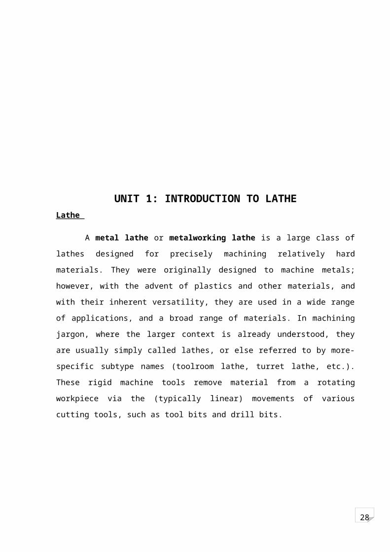
Figure 1 A Conventional Lathe Machine
1.1 COMPONENTS OF A LATHE MACHINE
I) Headstock
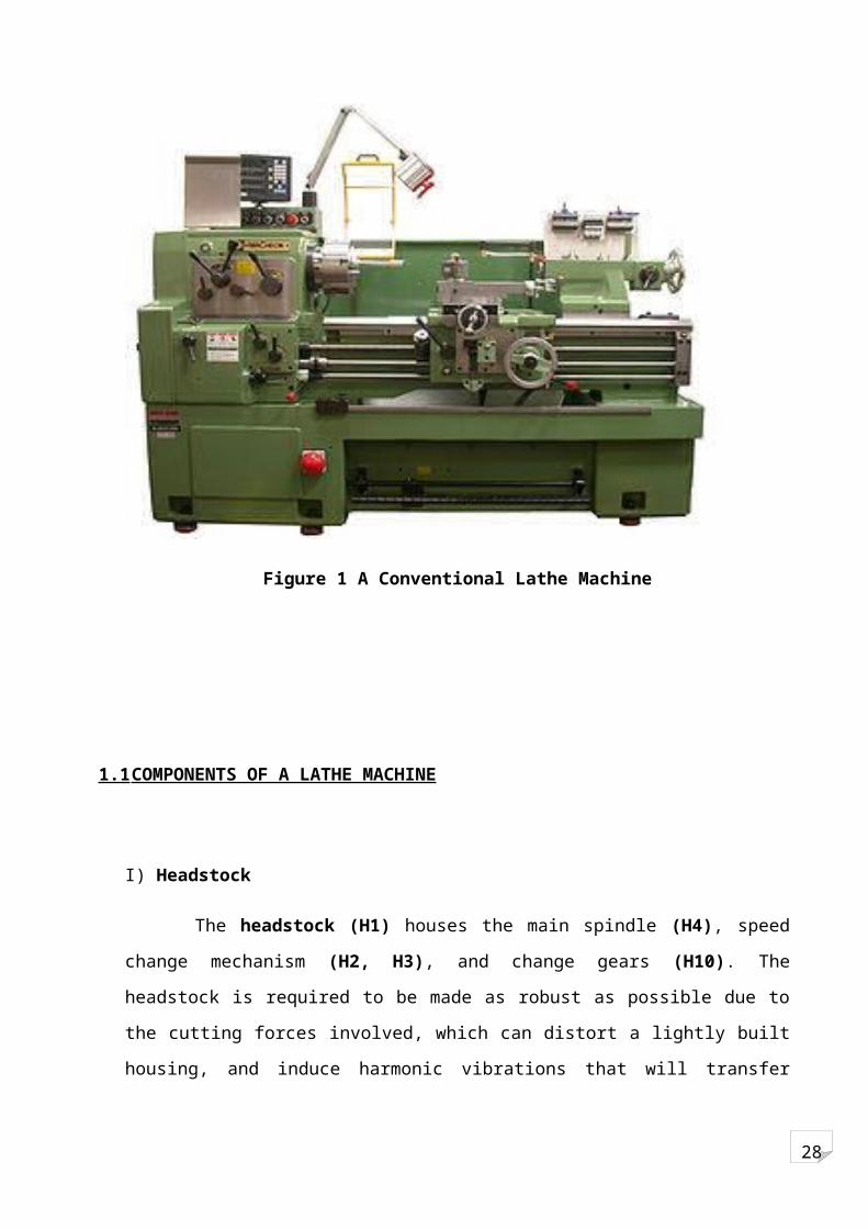
The headstock (H1) houses the main spindle (H4), speed change mechanism (H2, H3),
and change gears (H10). The headstock is required to be made as robust as possible due to the
cutting forces involved, which can distort a lightly built housing, and induce harmonic
vibrations that will transfer through to the workpiece, reducing the quality of the finished
workpiece.

28
Figure 2 HEADSTOCK
The main spindle is generally hollow to allow long bars to extend through to the work area;
this reduces preparation and waste of material. The spindle then runs in precision bearings and
is fitted with some means of attaching work holding devices such as chucks or faceplates. This
end of the spindle will also have an included taper, usually Morse, to allow the insertion of
tapers and centers. On older machines the spindle was directly driven by a flat belt pulley with
the lower speeds available by manipulating the bull gear, later machines use a gear box driven
by a dedicated electric motor. The fully geared head allows the speed selection to be done
entirely through the gearbox.
II) Bed
The bed is a robust base that connects to the headstock and permits the carriage and
tailstock to be aligned parallel with the axis of the spindle. This is facilitated by hardened and
ground ways which restrain the carriage and tailstock in a set track. The carriage travels by
means of a rack and pinion system, leadscrew of accurate pitch, or feedscrew.
28
When a lathe is installed, the first step is to level it, which refers to making sure the bed is
not twisted or bowed. There is no need to make the machine exactly horizontal. However, a
precision level (usually across the cross slide) can be a useful tool for identifying and
removing twist. It is advisable also to use such a level along the bed to detect bending, in the
case of a lathe with more than four mounting points. In both instances the level is used as a
comparator rather than an absolute reference.
Types of beds include inverted "V" beds, flat beds, and combination "V" and flat beds. "V"
and combination beds are used for precision and light duty work, while flat beds are used for
heavy duty work.
III) Feed and lead screws
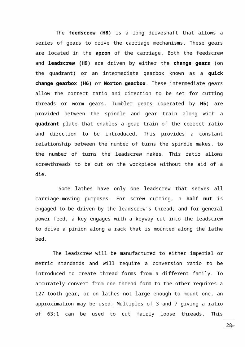
The feedscrew (H8) is a long driveshaft that allows a series of gears to drive the carriage
mechanisms. These gears are located in the apron of the carriage. Both the feedscrew and
leadscrew (H9) are driven by either the change gears (on the quadrant) or an intermediate
gearbox known as a quick change gearbox (H6) or Norton gearbox. These intermediate
gears allow the correct ratio and direction to be set for cutting threads or worm gears. Tumbler
gears (operated by H5) are provided between the spindle and gear train along with a quadrant
plate that enables a gear train of the correct ratio and direction to be introduced. This provides
a constant relationship between the number of turns the spindle makes, to the number of turns
the leadscrew makes. This ratio allows screwthreads to be cut on the workpiece without the
aid of a die.
Some lathes have only one leadscrew that serves all carriage-moving purposes. For screw
cutting, a half nut is engaged to be driven by the leadscrew's thread; and for general power
feed, a key engages with a keyway cut into the leadscrew to drive a pinion along a rack that is
mounted along the lathe bed.
The leadscrew will be manufactured to either imperial or metric standards and will require
a conversion ratio to be introduced to create thread forms from a different family. To
accurately convert from one thread form to the other requires a 127-tooth gear, or on lathes not
large enough to mount one, an approximation may be used. Multiples of 3 and 7 giving a ratio
of 63:1 can be used to cut fairly loose threads. This conversion ratio is often built into the
quick change gearboxes.
IV) Carriage
28
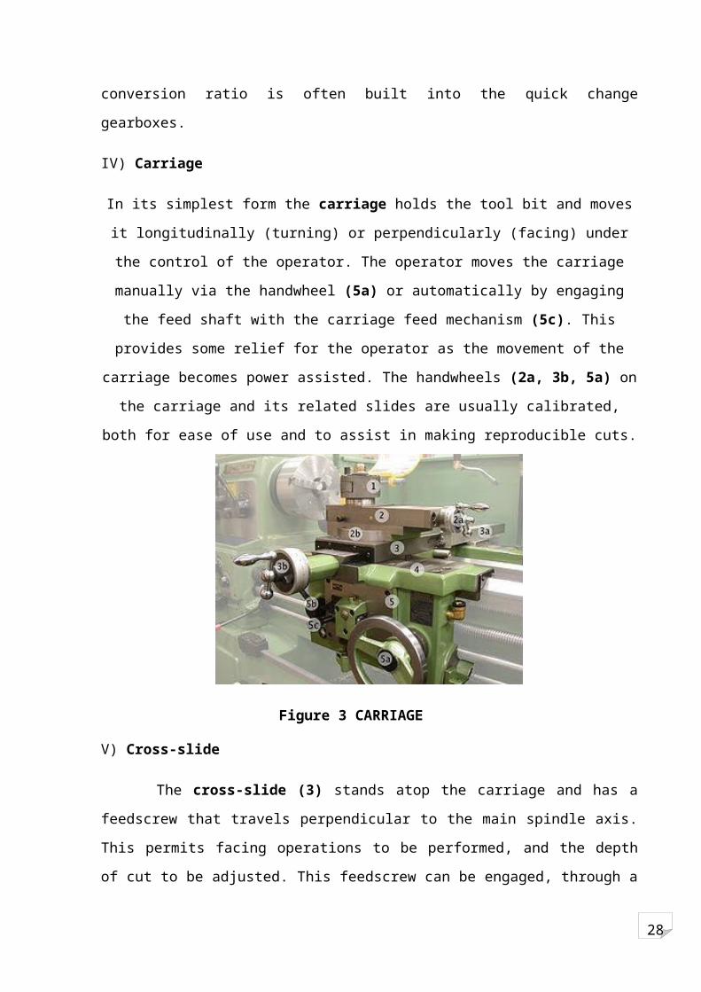
In its simplest form the carriage holds the tool bit and moves it longitudinally (turning) or
perpendicularly (facing) under the control of the operator. The operator moves the carriage
manually via the handwheel (5a) or automatically by engaging the feed shaft with the carriage
feed mechanism (5c). This provides some relief for the operator as the movement of the
carriage becomes power assisted. The handwheels (2a, 3b, 5a) on the carriage and its related
slides are usually calibrated, both for ease of use and to assist in making reproducible cuts.
Figure 3 CARRIAGE
V) Cross-slide
The cross-slide (3) stands atop the carriage and has a feedscrew that travels perpendicular
to the main spindle axis. This permits facing operations to be performed, and the depth of cut
to be adjusted. This feedscrew can be engaged, through a gear train, to the feed shaft
(mentioned previously) to provide automated 'power feed' movement to the cross-slide. On
most lathes, only one direction can be engaged at a time as an interlock mechanism will shut
out the second gear train
VI) Compound rest
The compound rest (2) (or top slide) is the part of the machine where the tool post is
mounted. It provides a smaller amount of movement along its axis via another feedscrew. The
compound rest axis can be adjusted independently of the carriage or cross-slide. It is utilized
when turning tapers, to control depth of cut when screwcutting or precision facing, or to obtain
finer feeds (under manual control) than the feed shaft permits.
28
The slide rest can be traced to the fifteenth century, and in the eighteenth century it was
used on French ornamental turning lathes. The suite of gun boring mills at the Royal Arsenal,
Woolwich, in the 1780s by the Verbruggan family also had slide rests. The story has long
circulated that Henry Maudslay invented it, but he did not (and never claimed so). The legend
that Maudslay invented the slide rest originated with James Nasmyth, who wrote ambiguously
about it in his Remarks on the Introduction of the Slide Principle, 1841; later writers
misunderstood, and propagated the error. Maudslay did help to disseminate the idea widely. It
is highly probable that he saw it when he was working at the Arsenal as a boy. In 1794, whilst
he was working for Joseph Bramah, he made one, and when he had his own workshop used it
extensively in the lathes he made and sold there. Coupled with the network of engineers he
trained, this ensured the slide rest became widely known and copied by other lathe makers,
and so diffused throughout British engineering workshops. A practical and versatile screw-
cutting lathe incorporating the trio of leadscrew, change gears, and slide rest was Maudslay's
most important achievement.
The first fully documented, all-metal slide rest lathe was invented by Jacques de
Vaucanson around 1751. It was described in the Encyclopédie a long time before Maudslay
invented and perfected his version. It is likely that Maudslay was not aware of Vaucanson's
work, since his first versions of the slide rest had many errors which were not present in the
Vaucanson lathe.
VII) Toolpost
The tool bit is mounted in the toolpost (1) which may be of the American lantern style,
traditional four sided square style, or in a quick change style such as the multifix arrangement
pictured. The advantage of a quick change set-up is to allow an unlimited number of tools to
be used (up to the number of holders available) rather than being limited to 1 tool with the
lantern style, or 3 to 4 tools with the 4 sided type. Interchangeable tool holders allow the all
the tools to be preset to a center height that will not change, even if the holder is removed
from the machine.

28
VIII) Tailstock
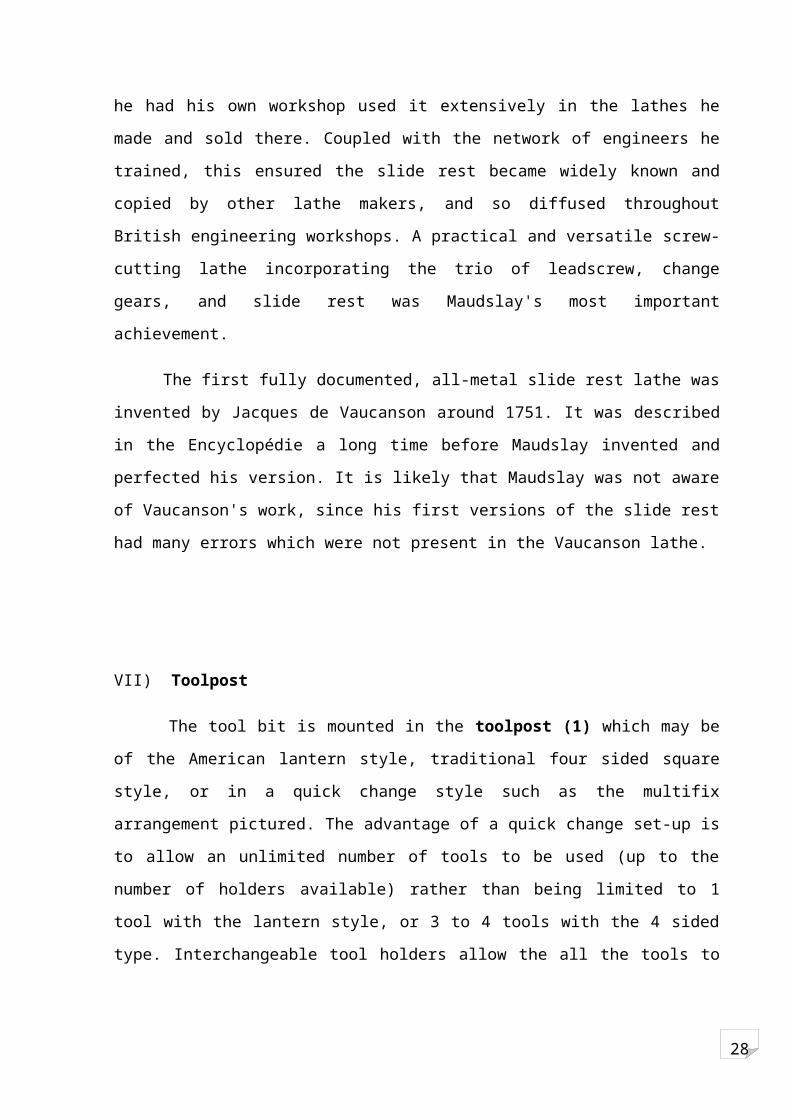
The tailstock is a toolholder directly mounted on the spindle axis, opposite the headstock.
The spindle (T5) does not rotate but does travel longitudinally under the action of a leadscrew
and handwheel (T1). The spindle includes a taper to hold drill bits, centers and other tooling.
The tailstock can be positioned along the bed and clamped (T6) in position as required. There
is also provision to offset the tailstock (T4) from the spindles axis; this is useful for turning
small tapers.
The image shows a reduction gear box (T2) between the handwheel and spindle, this is a
feature found only in the larger center lathes, where large drills may necessitate the extra
leverage.
UNIT 2: INTRODUCTION TO CNC
Computer numerical control (CNC) is the numerical control system in which a dedicated
computer is built into the control to perform basic and advanced NC functions. CNC controls
are also referred to as soft-wired NC systems because most of their control functions are
implemented by the control software programs. CNC is a computer assisted process to control
general purpose machines from instructions generated by a processor and stored in a memory
system. It is a specific form of control system where position is the principal controlled
variable. All numerical control machines manufactured since the seventies are of CNC type.
The computer allows for the following: storage of additional programs, program editing,
running of program from memory, machine and control diagnostics, special routines,
Figure 4: TAILSTOCK
28
inch/metric, incremental/absolute switchability.
CNC machines can be used as stand-alone units or in a network of machines such as flexible
machine centres. The controller uses a permanent resident program called an executive
program to process the codes into the electrical pulses that control the machine. In any CNC
machine, executive program resides in ROM and all the NC codes in RAM. The information
in ROM is written into the electronic chips and cannot be erased and they become active
whenever the machine is on. The contents in RAM are lost when the controller is turned off.
Some use special type of RAM called CMOS memory, which retains its contents even when
the power is turned off.
Figure 5: CNC LATHE MACHINE
2.1) ADVANTAGES OF A CNC MACHINE
1. Reduced Lead Time:
The time difference between the receipt of design drawing and the actual production on the
shop floor is called as the Lead Time. Since special jigs and fixtures are often entirely
eliminated in CNC machines the whole of time needed for their design and manufacturing is
saved.
2. Higher surface finish:
The surface finish of a workpiece varies directly with the cutting speed. In CNC higher
surface finish can be obtained due to constant cutting speed.
3. Elimination of Operator error:
28
The machine is controlled by program stored in the computer memory. The program is
checked for errors before it goes to machine. Fatigue, boredom or inattention by the operator
will not affect the quality or time of duration of machining.
4. Elimination of Special Jigs and Fixtures:
Standard locating fixtures are often not used in CNC machines. The capital cost of jig storage
facility is also eliminated. The storage of part program is a very simple matter, it may be kept
for many years and the manufacture of spare parts, and repeat orders is made much more
convenient.
5. Longer Tool Life:
Tools can be used at optimum speeds and feeds because these functions are controlled by the
part program. Programmed speeds and feeds can be overruled by the operator if difficulty in
machining is encountered.
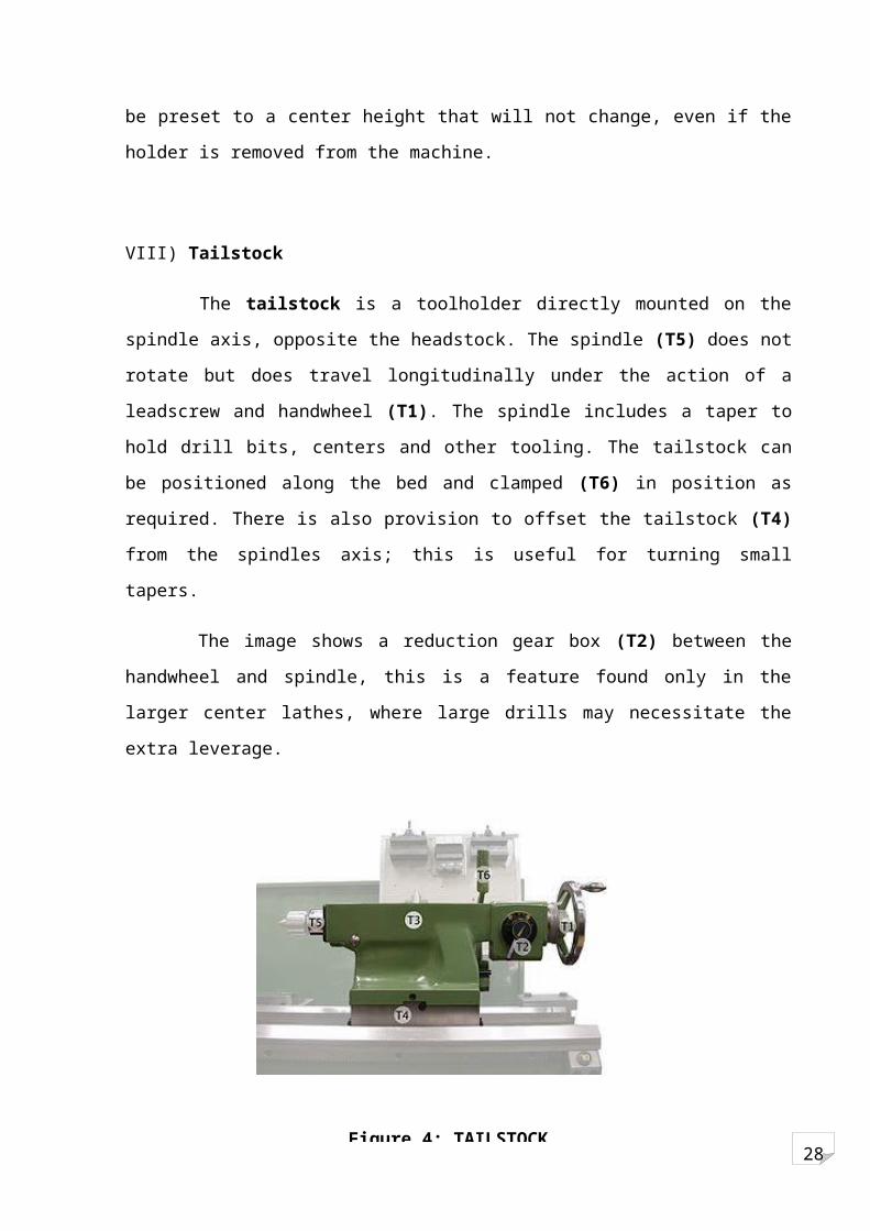
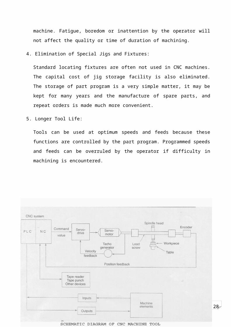
2.2) CONFIGURATION OF THE CNC SYSTEM
Fig. shows a schematic diagram of the working principle of a NC axis of a CNC machine and
the interface of a CNC control.

28
A CNC system basically consists of the following:
Central processing unit (CPU)
Servo-control unit
Operator control panel
Machine control panel
Other peripheral device
Programmable logic controller (PLC)
Basic Blocks of the CNC Machines
I) Central Processing Unit (CPU)
The CPU is the heart and brain of a CNC system. It accepts the information stored in the
memory as part program. This data is decoded and transformed into specific position control
and velocity control signals. It also oversees the movement of the control axis or spindle
whenever this does not match the programmed values, a corrective action is taken. All the
compensations required for machine accuracy (like lead screw pitch error, tool wear out,
backlash, etc.) are calculated by the CPU depending upon the corresponding inputs made
available to the system. The same will be taken care of during the generation of control signals
for the axis movement. Also, some safety checks are built into the system through this unit
and the CPU unit will provide continuous necessary corrective actions. Whenever the situation
goes beyond control of the CPU, it takes the final action of shutting down the system in turn
the machine.
II) Speed Control Unit
This unit acts in unison with the CPU for the movement of the machine axes. The CPU
sends the control signals generated for the movement of the axis to the servo control unit and
the servo control unit converts these signals into the suitable digital or analog signal to be fed
to the machine tool axis movement. This also checks whether machine tool axis movement is
at the same speed as directed by the CPU. In case any safety conditions related to the axis are
overruled during movement or otherwise they are reported to the CPU for corrective action.
Figure 6

28
III) Servo-Control Unit
The decoded position and velocity control signals, generated by the CPU for the axis
movement forms the input to the servo-control unit. This unit in turn generates suitable signals
as command values. The servo-drive unit converts the command values, which are interfaced
with the axis and the spindle motors (Fig.). The servo-control unit receives the position
feedback signals for actual movement of the machine tool axes from the feedback devices
(like linear scales, rotary encoders, resolves, etc.). The velocity feedback is generally obtained
through tacho generators. The feedback signals are passed on to the CPU for further
processing. Thus the servo-control unit performs the data communication between the
machine tool and the CPU. As explained earlier, the actual movements of the slides on the
machine tool is achieved through servo drives. The amount of movement and the rate of
movement are controlled by the CNC system depending upon the type of feedback system
used, i.e. closed-loop or open-loop system.
IV) Closed-loop System
The closed-loop system is characterized by the presence of feedback. In this system, the
CNC system send out commands for movement and the result is continuously monitored by
the system through various feedback devices. There are generally two types of feedback to a
CNC system --position feedback and velocity feedback.
V) Position feedback
A closed-loop system, regardless of the type of feedback device, will constantly try to
achieve and maintain a given position by self-correcting. As the slide of the machine tool
moves, its movement is fed back to the CNC system for determining the position of the slide
to decide how much is yet to be traveled and also to decide whether the movement is as per
the commanded rate. If the actual rate is not as per the required rate, the system tries to correct
it. In case this is not possible, the system declares fault and initiates action for disabling the
drives and if necessary, switches off the machine.
VI) Velocity feedback
In case no time constraint is put on the system to reach the final programmed position, then
the system may not produce the required path or the surface finish accuracy. Hence, velocity
feedback must be present along with the position feedback whenever CNC system are used for
28
contouring, in order to produce correct interpolation and also specified acceleration and
deceleration velocities. The tacho generator used for velocity feedback is normally connected
to the motor and it rotates whenever the motor rotates, thus giving an analog output
proportional to the speed of motor. The analog voltage is taken as speed feedback by the
servo-controller and swift action is taken by the controller to maintain the speed of the motor
within the required limits.
VII) Open loop system
The open loop system lacks feedback. In this system, the CNC system send out signals for
movement but does not check whether actual movement is taking place or not. Stepper motors
are used for actual movement and the electronics of these stepper motors is run on digital
pulses from the CNC system. Since system controllers have no access to any real time
information about the system performance, they cannot counteract disturbances appearing
during the operation. They can be utilized in point to point system, where loading torque on
the axial motor is low and almost constant.
VIII) Servo drives
The servo-drive receives signals from the CNC system and transforms it into actual
movement on the machine. The actual rate of movement and direction depend upon the
command signal from CNC system. There are various types of servo-drives, viz., dc drives, ac
drives and stepper motor drives. A servo-drive consists of two parts, namely, the motor and
the electronics for driving the motor.
IX) Operator control system
The operator control panel provides the user interface to facilitate a two-way
communication between the user, CNC system and the machine tool.
This consists of two parts:
Video Display Unit (VDU)
Keyboard
Visual display unit (VDU)
The VDU displays the status of the various parameters of the CNC system and the machine
tool. It displays all current information such as:

28
Complete information of the block currently being executed
Actual position value, set or actual difference, current feed rate, spindle speed
Active G functions
Main program number, subroutine number
Display of all entered data, user programs, user data, machine data, etc.
Alarm messages in plain text
Soft key designations
In addition to a CRT, a few LEDs are generally provided to indicate important operating
modes and status. Video display units may be of two types:
1. Monochrome or black and white displays
2. Color displays
X) Machine control panel (MCP)
It is the direct interface between operator and the NC system, enabling the operation of the
machine through the CNC system. During program execution, the CNC controls the axis
motion, spindle function or tool function on a machine tool, depending upon the part program
stored in the memory. Prior to the starting of the machine process, machine should first be
prepared with some specific tasks like,
·Establishing a correct reference point
·Loading the system memory with the required part program
·Loading and checking of tool offsets, zero offsets, etc.
For these tasks, the system must be operated in specific operating mode so that these
preparatory functions can be established.
Control elements of the Machine Control Panel
Modes of Operation
Generally, the CNC system can be operated in the following modes:
Manual mode (JOG mode)
Manual data input (MDI) mode
Automatic mode
Reference mode
Other peripherals
These include sensor interface, provision for communication equipment, programming
units, printer, tape reader/puncher interface, etc.
28
Programmable Logic circuit (PLC)
A PLC matches the NC to the machine. PLCs were basically introduced as replacement for
hard wired relay control panels. They were developed to be reprogrammed without hardware
changes when requirements were altered and thus are reusable. PLCs are now available with
increased functions, more memory and large input/output capabilities. In the CPU, all the
decisions are made relative to controlling a machine or a process. The CPU receives input
data, performs logical decisions based upon stored programs and drives the outputs.
Connections to a computer for hierarchical control are done via the CPU. The I/O structure of
the PLCs is one of their major strengths. The inputs can be push buttons, limit switches, relay
contacts, analog sensor, selector switches, proximity switches, float switches, etc. The outputs
can be motor starters, solenoid valves, position valves, relay coils, indicator lights, LED
displays, etc. The field devices are typically selected, supplied and installed by the machine
tool builder or the end user. The voltage level of the field devices thus normally determines
the type of I/O. So, power to actuate these devices must also be supplied external to the PLC.
The PLC power supply is designated and rated only to operate the internal portions of the I/O
structures, and not the field devices. A wide variety of voltages, current capacities and types of
I/O modules are available
Unit 3: Components in CNC Machine(A) Mechanical:
The drive units of the carriages in NC machine tools are generally the screw & the nut mechanism. There are different types of screws and nuts used on NC machine tools which provide low wear, higher efficiency, low friction and better reliability.
3.1 Ball Screw
(i) Recirculating ball screw
The recirculating ball screw assembly shown in figure 25.1 has the flanged nut attached to the moving chamber and the screw to the fixed casting. Thus the moving member will move during rotational movement of the screw. These recirculating ball screw designs can have ball gages of internal or external return, but all of them are based upon the "Ogival" or "Gothic arc".
In these types of screws, balls rotate between the screw and nut and convert the sliding friction (as in conventional nut & screw) to the rolling friction. As a consequence wear will be reduced and reliability of the system will be increased. The traditional ACME thread used in

28
conventional machine tool has efficiency ranging from 20% to 30% whereas the efficiency of ball screws may reach up to 90%.
Fig No.7 Recirculating ball screw assembly
Fig No. 8 Preloaded recirculating ball screw
(ii) Roller screw
Fig No. 9 Roller Screw
These types of screws provide backlash-free movement and their efficiency is same as that of ball screws. These are capable of providing more accurate position control. Cost of the roller
28
screws are more compared to ball screws. The thread form is triangular with an included angle of 90 degrees. There are two types of roller screws: planetary and recirculating screws.
(2) Tool turrets
An advantage of using tool turrets is that the time taken for tool changing will be only the time taken for indexing the turret. Only limited number of tools can be held in the turret. Tool turrets shown in figures a, b & c are generally used in lathes. The entire turret can be removed from the machine for setting up of tools.
(a) Six station tool turret
(b) Eight station tool turret
(c) Twelve station tool turret

28
(B) ELECTRICAL COMPONENTS
3.3) RELAY:-
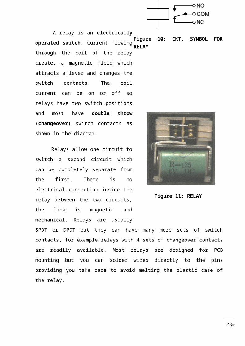
A relay is an electrically operated switch.
Current flowing through the coil of the relay
creates a magnetic field which attracts a lever
and changes the switch contacts. The coil
current can be on or off so relays have two
switch positions and most have double throw
(changeover) switch contacts as shown in the
diagram.
Relays allow one circuit to switch a second
circuit which can be completely separate from
the first. There is no electrical connection inside
the relay between the two circuits; the link is
magnetic and mechanical. Relays are usually
SPDT or DPDT but they can have many more sets of switch contacts, for example relays with
4 sets of changeover contacts are readily available. Most relays are designed for PCB
mounting but you can solder wires directly to the pins providing you take care to avoid
melting the plastic case of the relay.
Figure 10: CKT. SYMBOL FOR RELAY
Figure 11: RELAY

28
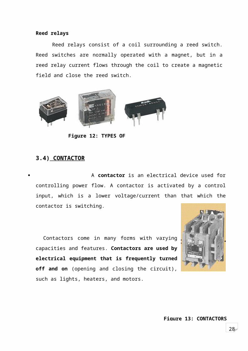
Reed relays
Reed relays consist of a coil surrounding a reed switch. Reed switches are normally
operated with a magnet, but in a reed relay current flows through the coil to create a
magnetic field and close the reed switch.
3.4) CONTACTOR
A contactor is an electrical device used for controlling power flow. A contactor is
activated by a control input, which is a lower voltage/current than that which the contactor is
switching.
Contactors come in many forms with varying capacities and
features. Contactors are used by electrical equipment that is
frequently turned off and on (opening and closing the circuit), such
as lights, heaters, and motors.
Contactor Components
The following components: an Electromagnet (E-frame), an Armature, a coil, a spring, and
two sets of contacts, one movable set and one stationary set.
Figure 12: TYPES OF RELAYS
Figure 13: CONTACTORS

28
Figure 14: LINE DIAGRAM OF CONTACTORS
Contactor Operation
So, how exactly does the contactor open and close?
The E-Frame, when energized by the coil, becomes an electromagnet. The armature, a
companion to the E-frame, is connected to a set of contacts.
The armature is moveable but is held by a spring.
Figure 15: CONSTRUCTION OF CONTACTORS

28
When the coil is energized, the moveable contacts are pulled toward the stationary contacts
because the armature is pulled toward the E-frame. Once the two sets of contacts meet,
power can flow through the contactor to the load.
Figure 16
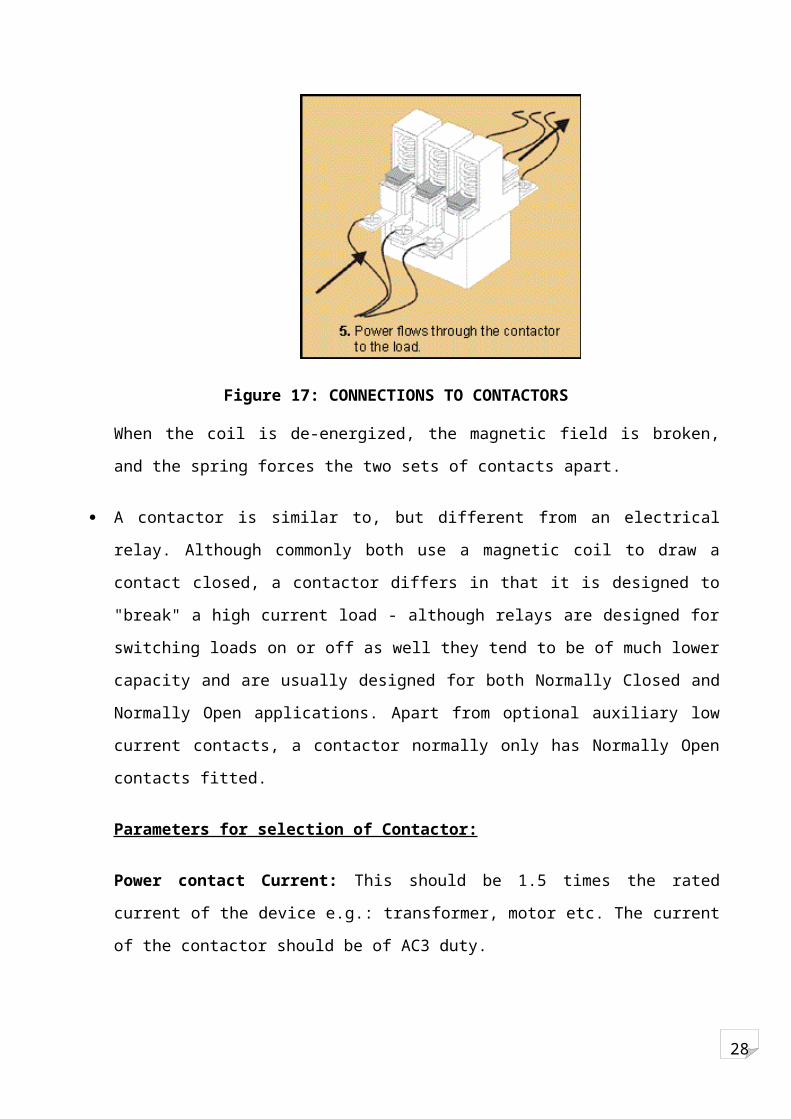
Figure 17: CONNECTIONS TO CONTACTORS
When the coil is de-energized, the magnetic field is broken, and the spring forces the two sets
of contacts apart.
A contactor is similar to, but different from an electrical relay. Although commonly both use a
magnetic coil to draw a contact closed, a contactor differs in that it is designed to "break" a
high current load - although relays are designed for switching loads on or off as well they tend
to be of much lower capacity and are usually designed for both Normally Closed and

28
Normally Open applications. Apart from optional auxiliary low current contacts, a contactor
normally only has Normally Open contacts fitted.
Parameters for selection of Contactor:
Power contact Current: This should be 1.5 times the rated current of the device e.g.:
transformer, motor etc. The current of the contactor should be of AC3 duty.
Coil Voltage selection: This will depend on Control voltage of the panel, usually we use
24VDC
Coil Current: Actual current taken by the electromagnetic coil of the contactor.
This is used for the calculation of the DC power supply sizing for 24VDC (in case control is
DC) or in selection of Control transformer sizing in case of AC control
Auxiliary Contact: Used for control circuit, should be selected only when extra control is needed.
E.g.: Motor–On feedback from the contactor to the PLC input.
3.5) Circuit Breaker:-
Definition
ANSI Definition: A circuit breaker is defined in ANSI standards as a
mechanical switching device capable of making, carrying, and breaking currents under normal
circuit conditions. Also, it is capable of making and carrying current for a specified time, and
breaking currents under specified abnormal circuit conditions such as those of a short circuit.
Circuit breakers provide a manual means of energizing and de-energizing a circuit. In
addition, circuit breakers provide automatic over-current protection of a circuit. A circuit
breaker allows a circuit to be reactivated quickly after a short circuit or overload is cleared.
Unlike fuses, which must be replaced when they open,
a simple flip of the breaker’s handle restores the
circuit

28
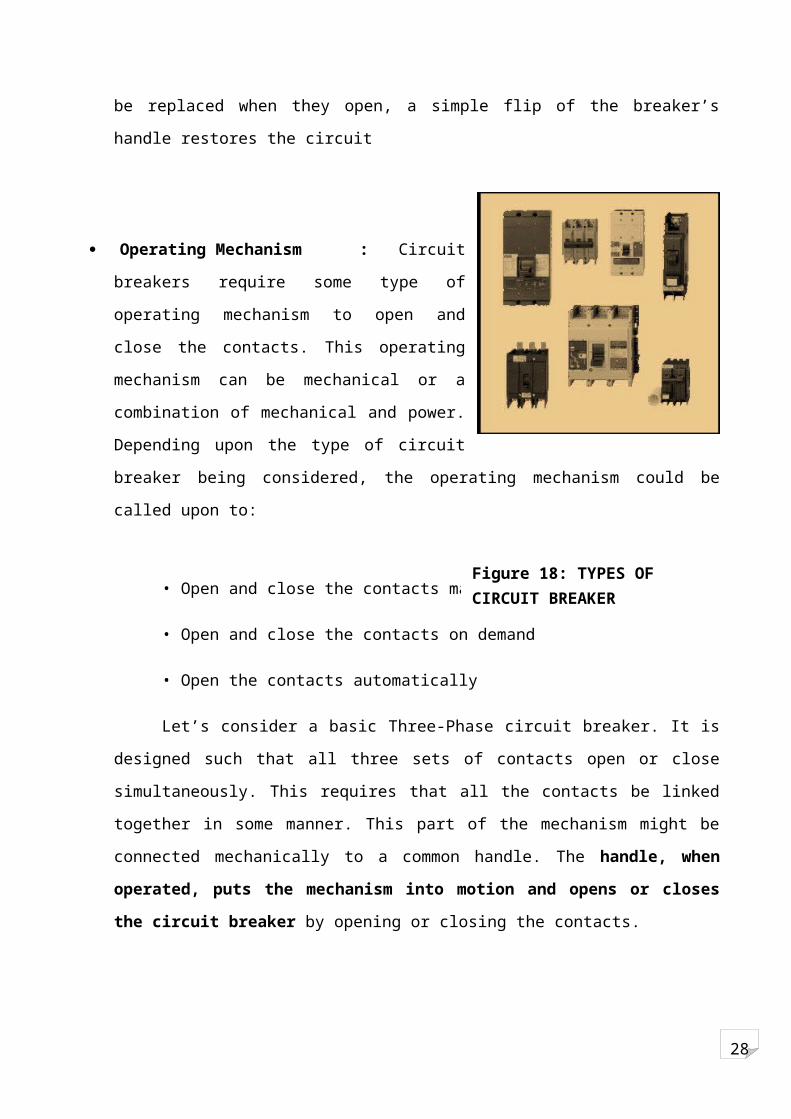
Operating Mechanism : Circuit breakers require some type of operating mechanism to
open and close the contacts. This operating mechanism can be mechanical or a combination of
mechanical and power. Depending upon the type of circuit breaker being considered, the
operating mechanism could be called upon to:
• Open and close the contacts manually
• Open and close the contacts on demand
• Open the contacts automatically
Let’s consider a basic Three-Phase circuit breaker. It is designed such that all three sets
of contacts open or close simultaneously. This requires that all the contacts be linked together
in some manner. This part of the mechanism might be connected mechanically to a common
handle. The handle, when operated, puts the mechanism into motion and opens or closes
the circuit breaker by opening or closing the contacts.
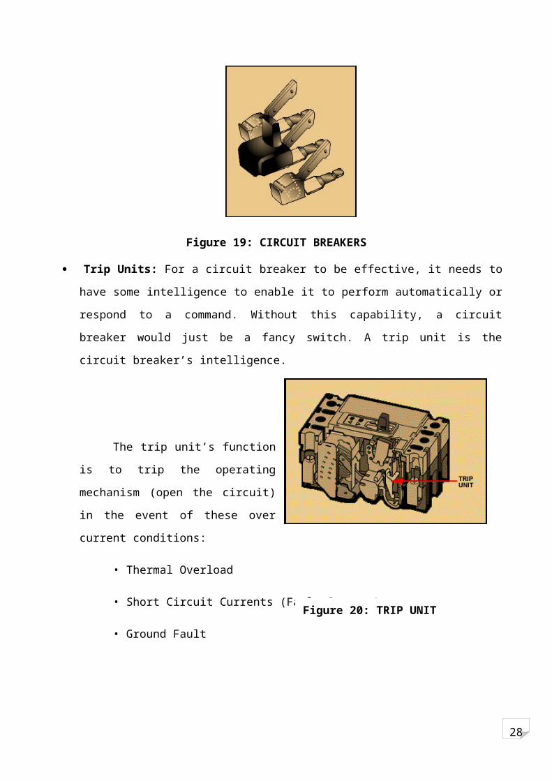
Figure 19: CIRCUIT BREAKERS
Trip Units: For a circuit breaker to be effective, it needs to have some intelligence to enable
it to perform automatically or respond to a command. Without this capability, a circuit breaker
would just be a fancy switch. A trip unit is the circuit breaker’s intelligence.
Figure 18: TYPES OF CIRCUIT BREAKER

28
The trip unit’s function is to trip the operating mechanism (open the circuit) in the
event of these over current conditions:
• Thermal Overload
• Short Circuit Currents (Fault Current)
• Ground Fault
1) Thermal Overload: When this condition exists, a temperature buildup occurs between
the insulation and the conductor. This is called a thermal overload.
2) Short Circuit Currents Short circuit currents (fault currents) usually occur with
abnormally high current flow due to the failure of conductor insulation. When the
insulation between phases breaks down, short circuit currents can be expected to flow into the
fault
3) Ground Fault A ground fault is a particular type of short circuit current fault. It is a short
circuit between one phase and ground.
Example: Circuit Breaker Operation In the following illustration an AC motor is
connected through a circuit breaker to a voltage source. When the circuit breaker is closed, a
complete path for current exists between the voltage source and the motor allowing the motor
to run. Opening the circuit breaker breaks the path of current flow and the motor stops. The
circuit breaker will open automatically during a fault, or can be manually opened. After the
fault has been cleared, the breaker can be closed allowing the motor to operate.
3.6) TRANSFORMER:
Electrical device used to transfer an alternating current or voltage from one electric circuit to
another by means of electromagnetic induction. A transformer does not generate electrical
power.
Figure 20: TRIP UNIT
28
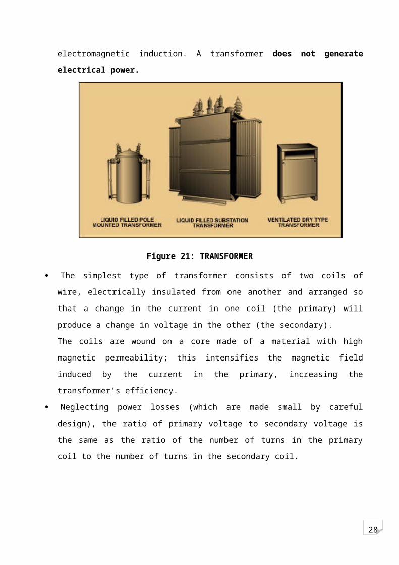
Figure 21: TRANSFORMER
The simplest type of transformer consists of two coils of wire, electrically insulated from one
another and arranged so that a change in the current in one coil (the primary) will produce a
change in voltage in the other (the secondary).
The coils are wound on a core made of a material with high magnetic permeability; this
intensifies the magnetic field induced by the current in the primary, increasing the
transformer's efficiency.
Neglecting power losses (which are made small by careful design), the ratio of primary
voltage to secondary voltage is the same as the ratio of the number of turns in the primary coil
to the number of turns in the secondary coil.
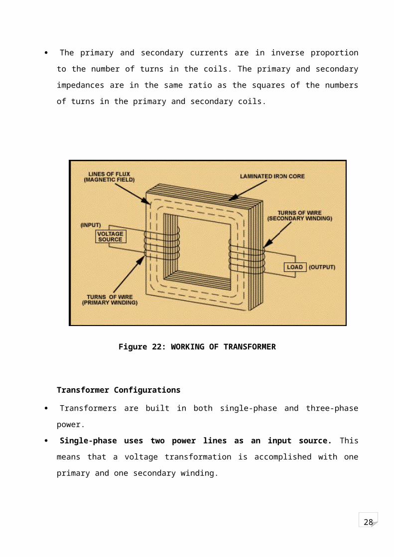
The primary and secondary currents are in inverse proportion to the number of turns in the
coils. The primary and secondary impedances are in the same ratio as the squares of the
numbers of turns in the primary and secondary coils.
28
Figure 22: WORKING OF TRANSFORMER
Transformer Configurations
Transformers are built in both single-phase and three-phase power.
Single-phase uses two power lines as an input source. This means that a voltage
transformation is accomplished with one primary and one secondary winding.
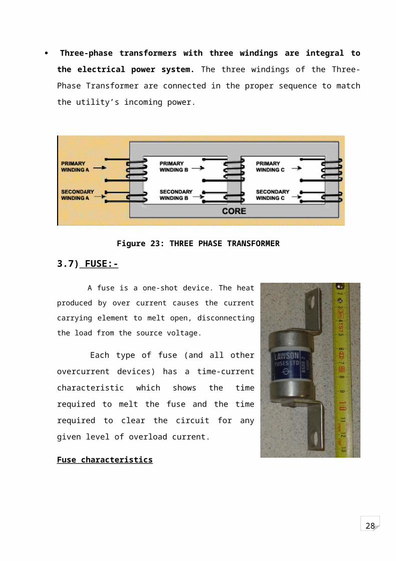
Three-phase transformers with three windings are integral to the electrical power
system. The three windings of the Three-Phase Transformer are connected in the proper
sequence to match the utility’s incoming power.
Figure 23: THREE PHASE TRANSFORMER

28
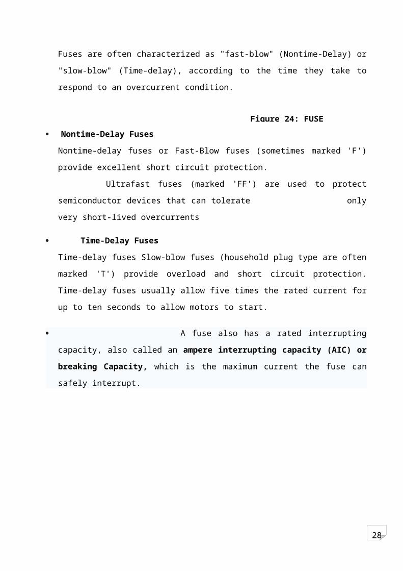
3.7) FUSE:-
A fuse is a one-shot device. The heat produced by over current
causes the current carrying element to melt open, disconnecting the
load from the source voltage.
Each type of fuse (and all other overcurrent devices) has a
time-current characteristic which shows the time required to
melt the fuse and the time required to clear the circuit for any
given level of overload current.
Fuse characteristics
Fuses are often characterized as "fast-blow" (Nontime-Delay)
or "slow-blow" (Time-delay), according to the time they take
to respond to an overcurrent condition.
Nontime-Delay Fuses
Nontime-delay fuses or Fast-Blow fuses (sometimes marked 'F') provide excellent short circuit
protection.
Ultrafast fuses (marked 'FF') are used to protect semiconductor devices that can tolerate
only very short-lived overcurrents
Time-Delay Fuses
Time-delay fuses Slow-blow fuses (household plug type are often marked 'T') provide
overload and short circuit protection. Time-delay fuses usually allow five times the rated
current for up to ten seconds to allow motors to start.
A fuse also has a rated interrupting capacity, also called an ampere interrupting
capacity (AIC) or breaking Capacity, which is the maximum current the fuse can safely
interrupt.
Figure 24: FUSE

28
SECTION II
General Steps to be followed for Retrofitting
UNIT 4: MECHANICAL ACTIVITIES
28
4.1) Dismantling of machine parts:
Removal of all electrical connections:
The main electrical supply is disconnected. All the external wires are stripped off since the
new machine has a complete new set off electrical system. The same case applies to the
internal wiring wherein all the visible wires are removed. Also the electrical junctions and
control panel mounted on the machine are removed. The various motors used in the lathe are
removed to be replaced with new ones.
Mechanical dismantling:
Major dismantling:
Removal of chip conveyor: All the external fittings are removed first since it facilitates the
dismantling of the lathe. Further dismantling of the assembly is carried afterwards.
Removal of external power pack: It consists of hydraulic tank and motor supplying power to
all the hydraulic components. The tank is checked for leakage and if required it is replaced.
Removal of external piping: All the connections between the power pack and the various
components are removed. Similar to the case of electrical connections the pipes are replaced
with new ones.
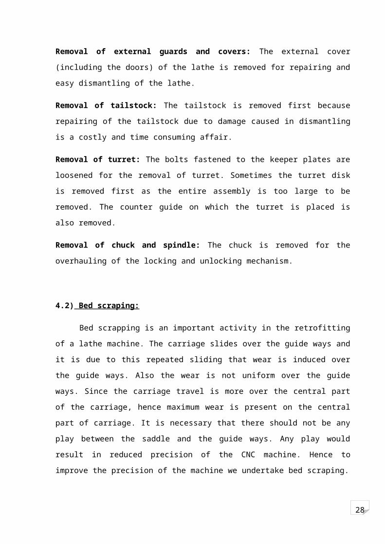
Removal of external guards and covers: The external cover (including the doors) of the
lathe is removed for repairing and easy dismantling of the lathe.
Removal of tailstock: The tailstock is removed first because repairing of the tailstock due to
damage caused in dismantling is a costly and time consuming affair.
Removal of turret: The bolts fastened to the keeper plates are loosened for the removal of
turret. Sometimes the turret disk is removed first as the entire assembly is too large to be
removed. The counter guide on which the turret is placed is also removed.
Removal of chuck and spindle: The chuck is removed for the overhauling of the locking and
unlocking mechanism.
4.2) Bed scraping:

28
Bed scrapping is an important activity in the retrofitting of a lathe machine. The carriage
slides over the guide ways and it is due to this repeated sliding that wear is induced over the
guide ways. Also the wear is not uniform over the guide ways. Since the carriage travel is
more over the central part of the carriage, hence maximum wear is present on the central part
of carriage. It is necessary that there should not be any play between the saddle and the guide
ways. Any play would result in reduced precision of the CNC machine. Hence to improve the
precision of the machine we undertake bed scraping.
Before starting with the actual scraping it is necessary that all the components on the bed
are removed. These components are saddle (along with turret) and tailstock. We know that the
tailstock is removed first to protect it from the damage. The turret is mounted on the saddle
along with the mechanism for the cross travel. These components are removed and the saddle
is made to slide along the guide ways to see for any obstructions to the movement of the
saddle. Now the saddle is ready to be removed from the bed.
The saddle is attached to the guide ways with help of keeper plates. Keeper plates also
prevent the saddle from tumbling down in case of slant bed machines. To remove the saddle
these keeper plates are removed first. Once the plates have been removed we can easily
remove the saddle
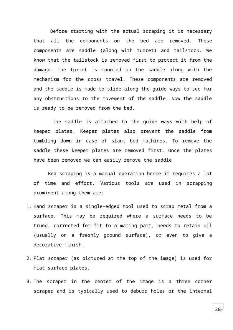
Bed scraping is a manual operation hence it requires a lot of time and effort. Various tools
are used in scrapping prominent among them are:
1. Hand scraper is a single-edged tool used to scrap metal from a surface. This may be required
where a surface needs to be trued, corrected for fit to a mating part, needs to retain oil (usually
on a freshly ground surface), or even to give a decorative finish.
2. Flat scraper (as pictured at the top of the image) is used for flat surface plates.
3. The scraper in the center of the image is a three corner scraper and is typically used to deburr
holes or the internal surface of bush type bearings. Bushes are typically made from bronze or a
white metal.
4. The scraper pictured at the bottom is a curved scraper. It has a slight curve in its profile and is
also suitable for bush bearings, typically the longer ones.
28
Figure 25: SCRAPING TOOL
The scraper materials are generally carbide (for scraping hardened steel) or white bit (for
scraping Mild Steel & Cast Iron).
Also if the quantity of material to be removed is large grinding machine is used although
manual scraping is more accurate (up to 4 microns). The amount of material to be removed
can be decided by using Prussian blue (a type of ink). The ink is applied on a master plate
which is used as a reference for flatness of the surface. The master plate slides over the guide
way and highlights the high spots on the guide ways. These high spots are scraped and once
all high spots have been scraped the master plate is once again used to highlight the high
spots. This procedure of highlighting and scraping is continued till the entire surface is
uniformly highlighted which signifies flatness of the surface. After the surface has been
scraped the surfaces of the carriage are checked for perpendicularity using the ‘L’ plates. To
check whether the guide ways are horizontal or not spirit level indicators (sensitivity of 20
microns/meter) are used.
Since the guideways have been scraped the saddle will not fit properly on the guideways
therefore a thin sheet of antifriction material like Turcite, Micarda, Hylum (used for very high
loads) is used to fill the gap between the saddle and the carriage. The antifriction sheets are
available in standard dimensions. The thickness of the antifriction material could more than
the gap. To compensate for the extra thickness of the sheet, some material from the counter
guide is scraped off. The saddle is attached to the guideways using taper jib which also takes
care of longitudinal play.
28
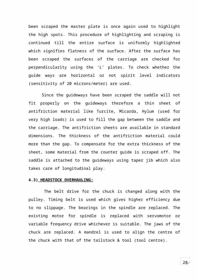
4.3) HEADSTOCK OVERHAULING:
The belt drive for the chuck is changed along with the pulley. Timing belt is used which
gives higher efficiency due to no slippage. The bearings in the spindle are replaced. The
existing motor for spindle is replaced with servomotor or variable frequency drive whichever
is suitable. The jaws of the chuck are replaced. A mandrel is used to align the centre of the
chuck with that of the tailstock & tool (tool centre).
Figure 26: CHUCH OVERHAULING
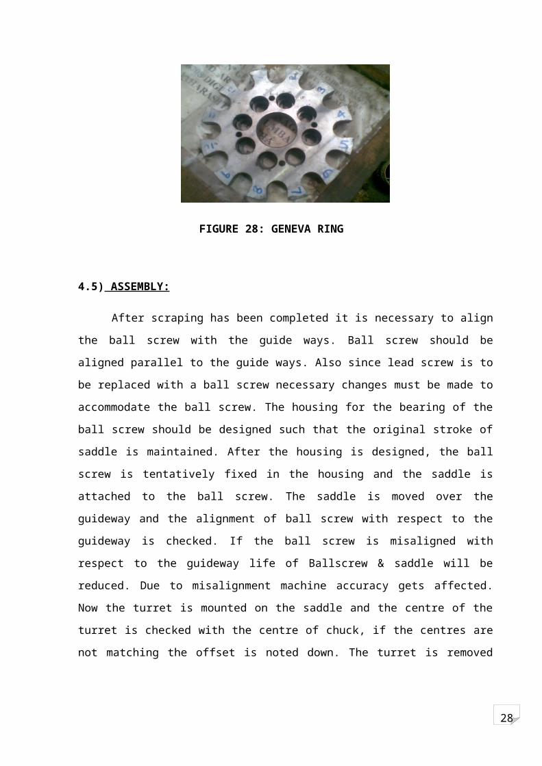
4.4) TURRET OVERHAULING:
The turret is generally a hydraulically operated device. The turret is dismantled further with
removal and replacement of all mechanical seals, piping, solenoids, cables etc. The splined
shaft and the Geneva ring are checked for wear and if necessary they are replaced.
MANDREL
CHUCK

28
Figure 27: TURRET
FIGURE 28: GENEVA RING
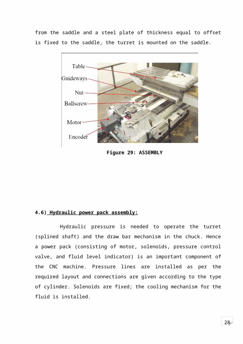
4.5) ASSEMBLY:
After scraping has been completed it is necessary to align the ball screw with the guide
ways. Ball screw should be aligned parallel to the guide ways. Also since lead screw is to be
replaced with a ball screw necessary changes must be made to accommodate the ball screw.
The housing for the bearing of the ball screw should be designed such that the original stroke
of saddle is maintained. After the housing is designed, the ball screw is tentatively fixed in the
housing and the saddle is attached to the ball screw. The saddle is moved over the guideway
and the alignment of ball screw with respect to the guideway is checked. If the ball screw is
misaligned with respect to the guideway life of Ballscrew & saddle will be reduced. Due to
misalignment machine accuracy gets affected. Now the turret is mounted on the saddle and the
centre of the turret is checked with the centre of chuck, if the centres are not matching the
28
offset is noted down. The turret is removed from the saddle and a steel plate of thickness equal
to offset is fixed to the saddle, the turret is mounted on the saddle.
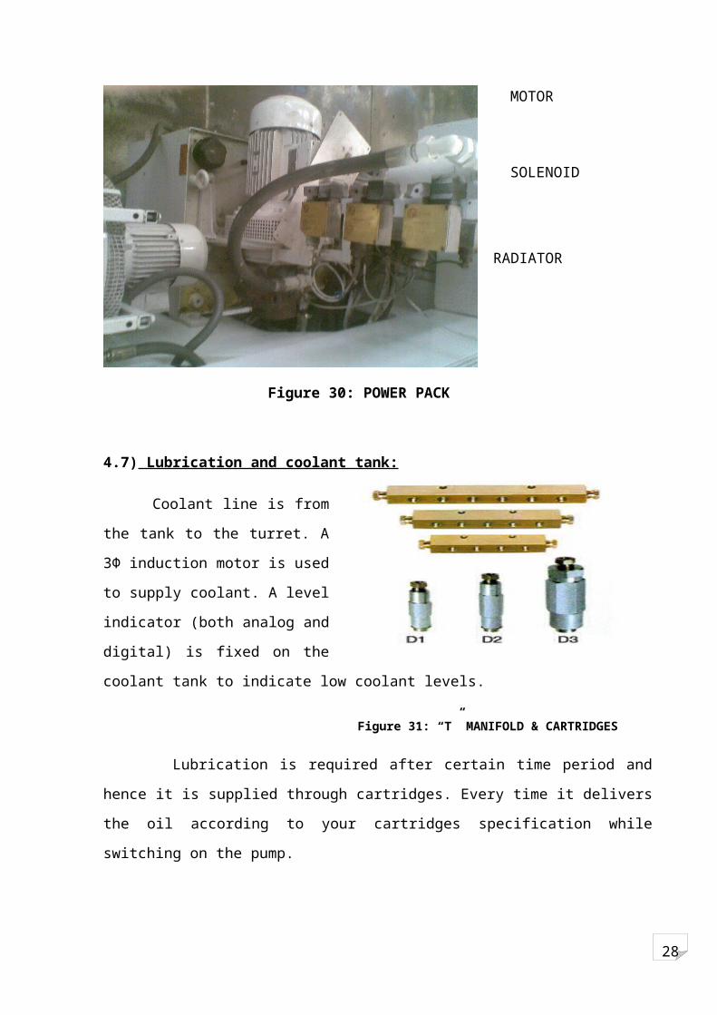
4.6) Hydraulic power pack assembly:
Hydraulic pressure is needed to operate the turret (splined shaft) and the draw bar
mechanism in the chuck. Hence a power pack (consisting of motor, solenoids, pressure control
valve, and fluid level indicator) is an important component of the CNC machine. Pressure
lines are installed as per the required layout and connections are given according to the type of
cylinder. Solenoids are fixed; the cooling mechanism for the fluid is installed.
Figure 29: ASSEMBLY
28
Figure 30: POWER PACK
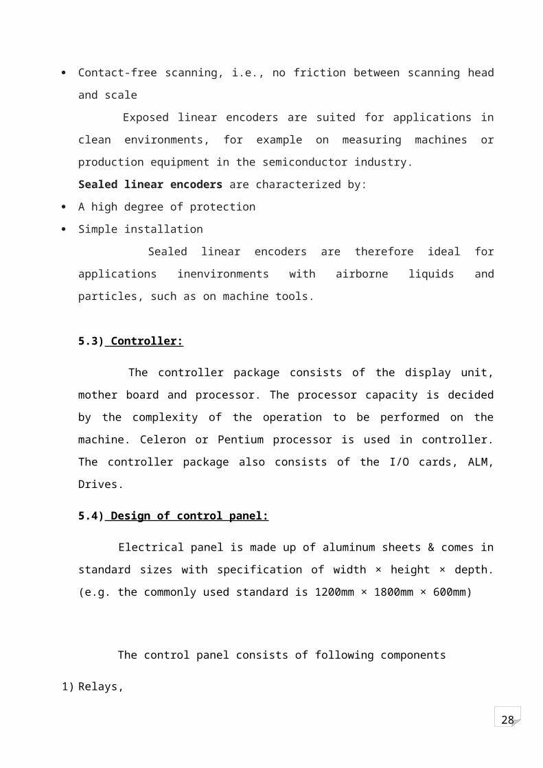
4.7) Lubrication and coolant tank:
Coolant line is from the tank to the
turret. A 3Φ induction motor is used to
supply coolant. A level indicator (both
analog and digital) is fixed on the
coolant tank to indicate low coolant
levels.
Lubrication is required after certain time period and hence it is supplied through
cartridges. Every time it delivers the oil according to your cartridges specification while
switching on the pump.
MOTOR
SOLENOID
RADIATOR
Figure 31: “T” MANIFOLD & CARTRIDGES
28
UNIT 5: ELECTRICAL ACTIVITIES
5.1) Limit Switches Fixing:
Limit switches are used as hard limits for the strokes in both the axes in CNC machine.
The dog of the limit switch is fixed on the stationary part (guideways of X & Z axes) & the
plunger is fixed on the moving part (saddle).
Both the dog & the plunger are screwed as they are small in size & it is not possible to bolt
them due to the thickness of the components on which they are fixed.
Figure 32: LIMIT SWITCHES
5.2) Encoder Installation:
Rotary encoder (2500 PPR) is fixed inside the head stock assembly. The insulating disc in
mounted on the shaft and the metal sheet is attached to the disc. The sheet is engraved into
specific no of sectors. Sliding contacts are fixed on the stationary object and electrical
connection is given to both. Linear encoder is fixed below the guideway & scanning unit is
mounted on the saddle. The feedback is given to the drivers.
DOG OF LIMIT SWITCH
28
Linear encoders for linear motors
Linear encoders on linear motors supply the actual value both for the position controller
and the velocity controller. They therefore form the basis for the servo characteristics of a
linear drive. The linear encoders recommended for this application:
Have low position deviation during acceleration in the measuring direction
Have high tolerance to acceleration and vibration in the lateral direction
Are designed for high velocities
Supply sinusoidal incremental signals of high quality
Exposed linear encoders are characterized by:
Higher accuracy grades
Higher traversing speeds
Contact-free scanning, i.e., no friction between scanning head and scale
Exposed linear encoders are suited for applications in clean environments, for example on
measuring machines or production equipment in the semiconductor industry.
Sealed linear encoders are characterized by:
A high degree of protection
Simple installation
Sealed linear encoders are therefore ideal for applications inenvironments with airborne
liquids and particles, such as on machine tools.
5.3) Controller:
The controller package consists of the display unit, mother board and processor. The
processor capacity is decided by the complexity of the operation to be performed on the
machine. Celeron or Pentium processor is used in controller. The controller package also
consists of the I/O cards, ALM, Drives.
5.4) Design of control panel:
Electrical panel is made up of aluminum sheets & comes in standard sizes with
specification of width × height × depth. (e.g. the commonly used standard is 1200mm ×
1800mm × 600mm)

28
The control panel consists of following components
1) Relays,
2) Contactors,
3) Motor Protection Circuit Breaker (offering safeguard against over load, short circuit, ground
fault) ,
4) Circuit Breakers,
5) Drivers,
6) I/O card,
7) Active Line module (A.L.M.),
8) Transformers,
9) Regulated AC Rectifiers and
10) Fuse.
The number of relays is given by the sum of the nos. of relays used for solenoids, relays
used for limit switches, relays used to activate the servo drives (2 for A.L.M. and 1 for each
axis drive) and relays used to switch on the contactors. Contactors are required to switch on
the induction motors and hence they are equal to the number of induction motors. The number
of MPCB used is decided by the number of induction motors in the machine, one for each
motor. It consists of two drives, one for X and Z axis and one for the Y axis. Also one drive is
used for spindle motor. The panel consists of two I/O cards and one A.L.M. The number of
transformer is decided by the variable voltage required by the motors.
28
COMMISSIONING
Project commissioning is the process of assuring that all systems and components of a machine are designed, installed, tested, operated, and maintained according to the operational requirements of the owner or final client. A commissioning process may be applied not only to new projects but also to existing units and systems subject to expansion, renovation or revamping.
Commissioning of a CNC machine is the process of testing all the retrofitted components & ensuring their appropriate working.
Dry Run:
A dry run is a testing process where the effects of a possible failure are intentionally mitigated.
Machine after completion of mechanical & electrical activities is put to test first by operating it without any job.
Working of various parts of the machine is checked. Chuck is tested for proper rotation at specified RPM in both clockwise & counter-clockwise direction. Ball screw alignment is tested by running the carriage mounted over it. The difference between actual (or physical) distance travelled & the command given via CNC operator panel is measured. The difference would specify the error; this error is incorporated in the CNC system by feeding the error value to the PLC. If the error is more in value then the alignment is rechecked mechanically (generally the error is in microns). Similarly, cross-slide is also checked.
Job Trials:
After the machine runs successfully in the dry run, it is tested by actually doing machining processes of sample jobs.
Jobs of various diameters are machined by all the operations, like turning, facing, etc., for which the machine has been retrofitted.
The accuracy of all the machining operations is checked by manually measuring the dimensions of the machined job with calibrated measuring equipments.
28
Section III
Case Study:
Retrofitting of Panther lathe
28
UNIT 6: MECHANICAL ACTIVITIES
Steps to be followed in retrofitting of lathe machine are:
6.1) Dismantling of machine :
i. First of all the electrical supply is switched off and all the visible electrical connection are
stripped off.
ii. The tailstock is removed to prevent damage of the tailstock. Now the saddle containing the
cross slide is removed.
iii. The coolant tank is also detached from the machine.
iv. The 1.5kW motor is also detached from the machine since it is to be replaced.
6.2) Scraping of the slide:
The guideways are subjected to wear due to the traveling saddle. After removing the saddle,
guideways are scraped. Prussian blue is used to highlight the high spots on the guideways.
Scraper tip made of carbide is used for removal of material for beds made of hardened steel.
Dial gauge is used to check the flatness of the slide.
6.3) Headstock overhauling:
i. The gears are checked for visible damage and also backlash. If the backlash increases beyond
a particular limit they are changed.
ii. Since for the headstock, we are using VFD (Variable Frequency Drive) there is no need for the
gear changing mechanism (Tumbler Mechanism). The gears are set for maximum speed and
locked by inserting a steel piece. The gears for lead screw are removed along with the lead
screw itself.
iii. Even the feed shaft is removed since the new ball screw is going to be engaged with the saddle
through the flange nut forever.
iv. The number of grooves on the pulley is increased from 1 to 2. This leads to uniform
distribution of load and power and thus increasing belt life and increasing efficiency of power
transmission.
v. The spindle is checked for visible surface damages and overhauled. The jaws of the chuck are
replaced by new ones.

28
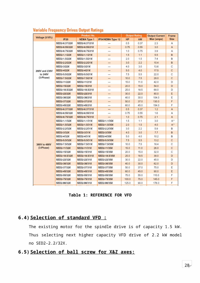
Table 1: REFERENCE FOR VFD
6.4) Selection of standard VFD :
The existing motor for the spindle drive is of capacity 1.5 kW. Thus selecting next higher
capacity VFD drive of 2.2 kW model no SED2-2.2/32X.
6.5) Selection of ball screw for X&Z axes:
Z axis: Φ40 mm 4TPI/ 6 mm pitch.
X axis: Φ30 mm 4TPI/6 mm pitch.
28
6.6) Selection of bearings:
For Z axis
Ball screw 40 4TPI / 6mm pitch
Ball screw support bearing:
BSB 030 062 (based on diameter of ball screw)…………………………… (RHP Manual pg 42)
For which
D = 62 , d1 = 37
B = 15 , D1 = 56
Ca = 26500 N, Co = 42800 N
Preload = 2250 N
Thrust ball bearing:
SKF 811206 TN (based on diameter) ……………………. (SKF Reference manual pg. 870)
For which
D = 52mm, d = 30 mm
C = 50 kN, C0 = 134 kN
H = 16 mm, Nlimiting = 4800 rpm.
For X axis
Ball screw 30 4TPI / 6mm pitch
Ball screw support bearing:
BSB 020 047 (based on diameter)………………………………………… (RHP Manual pg 42)
For which
Figure 33: SUPPORT BEARING
FIGURE 34: THRUST BALL BEARING

28
D = 47mm, B = 15mm
D1 = 42mm, d1 = 26mm
Thrust ball bearing:
SKF 51105 (based on diameter)…………………………(SKF Reference Manual Pg.842)
For which
D = 42mm, d = 25 mm
C = 18.2 KN, C0 = 39 kN
H = 11 mm, Nlimiting = 9000 rpm.
6.7) Forces acting on the support bearing:
For Z axis
Frictional torque due to preload
Tn =
= {no. of starts = 1
Lead = 1 = 6 mm}
= 4.295 kgf-m
= 0.4295 N-m
Radial load = 90% of preload
Preload = 2250 N
Radial load, R = 1012.5 N = 102 kgf
Total axial preload, Pa = +112.5
= 136 kgf
Axial components on each bearing:
28
Fa1 = Ta + Pa
Assuming external axial load = 20% of radial load
Ta = 20.4 kgf
Fa1 = 149.6 kgf
Fa2 = Pa Ta
= 136 (20.4)
Fa2 = 129.2 kgf
Radial component on each bearing:
Fr1 = {(Fa1) (2/3)/ ((Fa1) (2/3) (Fa2) (2/3))} ×R
{(149.6) (2/3) / ((149.6) (2/3) (129.2) (2/3))}
53.49 kgf
Fr2 {(Fa2) (2/3)/ ((Fa1) (2/3) (Fa2) (2/3))} ×R
= {(129.2) (2/3) / ((149.6) (2/3) (129.2) (2/3))}
48.51 kgf
6.8) Motor selection:
Torque acting on the ball screw:i. Frictional torque due to external load:
TP =
Where Tp = frictional torque
28
Fa = axial load
Fa = F +µw
F = cutting force
W =weight of table and work
µ = efficiency = 0.9
ii. Frictional torque due to preload:
Tn =
Where F0 = preload
l = lead
k = internal frictional coefficient of
preload nut (0.1 to 0.3)
iii. Load torque due to acceleration:
Tj = Jm× = Jm = Jm ((f2 f1)/t)
Where Tj = load torque (kgf-cm)
Jm = moment of inertia acting on
motor (kg-cm-sec2)
= Angular speed of motor
shaft (rad/sec2)
t = time for acceleration
= motor rotation/pulse
Fn = pulse rate =
Motor selection based on frictional torque due to external load and preload
Calculation for frictional torque
28
Cutting force, F = 6120 …………………………………………… (from CMTI Pg 637)
= 6120
= 19480.5 N
Fa F w
1948 (0.1) 100
1958 kgf
= 19580 N
( Tp)max
Tp
20.77 N-m
Tn =
=
= 0.429 N-m
Tmax = Tp + Tn
= 20.77 + 0.429
= 21.19 22 N-m
Selecting standard 2 servomotor (one for each axis) of torque 18 N-m and 1:2 reduction

28
6.9) Timing belt selection:
Timing belt is a molded endless belt with uniformly spaced teeth formed on one or both sides which provide positive action of a chain drive combined with most of the advantages of a belt drive.
Timing belt drive offers the following advantages:
1. There is no slippage, creep or speed variation during drive.
2. Timing belt can be used at speeds up to 80m/sec. and for a wide range of power from fractional kilowatt to as high as 400kW.
3. Since the belt does not rely on friction for power transmission, high initial tension is unnecessary & this results in lesser bearing loads.
4. Compact design is possible due to greater flexibility of the belt allowing for short centre distance, smaller pulleys & also due to a high power to weight ratio of the belt.
5. The tension member ensures no belt stretch & hence installation on fixed centre without any provision for belt adjustment is possible.
Timing belt drive is used for the Z axis ball screw.
The specifications are: (for 1:2 speed reduction)
Number of teeth on motor pulley = 18
Number of teeth on ball screw pulley = 36
Number of teeth on belt = 267
Length of belt = 1335mm
Centre to centre distance = 600mm
Diameter of motor pulley = 18× 5 = 90 mm
Diameter of ballscrew pulley = 36× 5 = 180mm
UNIT 7: ELECTRICAL ACTIVITIES
7.1) Limit switches fixing:
The retrofitted Panther lathe will have 5 limit switches. One for each axis and one to be fixed
on the tailstock.
Limit switch to be fixed on the axes:
Single plunger limit switch N1A, design: DIN 43693

28
Limit Switch on tailstock
TEKNIC EUCHNER NG/HB 510
7.2) Encoder installation:
The retrofitted CNC will have 3 encoders; 2 linear and 1 rotary. The linear encoders will be
used for finding the travel of the carriage on the two axes and the rotary encoder will be used
to measure the rotation of the spindle.
Figure 35: LINE DIAGRAM OF LIMIT SWITCH
Figure 36: TEKNIC EUCHNER LIMIT SWITCH
28
The linear spindle is of optical type
HEIDENHAIN LIDA 200 series
(for longitudinal travel)
Accuracy ± 3µm
Measuring length of up to 10000mm
HEIDENHAIN LIF 400 series
(For cross travel)
Accuracy ± 3µm
Measuring length of up to 1020 mm
Rotary encoders:
Figure 38: SERVO MOTOR
Rotary encoders are fixed in the motor itself.
7.3) Control panel for Panther lathe:
I) Installation of standard control panel of dimensions 1200mm×1800mm×600mm.
II) Installation of 3Φ, step down transformer output voltage 110V.
Gland
Figure 37: WORKING OF ENCODERS
FIGURE 39: GRATINGS ON ENCODERS

28
III) Installation of line filter, Active Line Module, drivers of X&Z axis. Selecting 802D solution
line with Celeron processor.
IV) Installation of relays on relay board :
The number of relays is given by the sum of relays
= No. of relays for solenoids + relays for induction motor + relays for the servo drives
+ relays for machine hard limit
= 0 + 1 + 4 + 5
= 10.
Make of relays: OMORON, 5A/24V D.C.
V) Installation of contactors:
The contactors are similar to relays, just that their current carrying capacity is higher. We
require 1 solenoid for switching of each induction motor. Hence in Panther lathe we require 1
contactor.
VI) Installation of motor protection circuit breakers:
MPCB are used to protect induction motor against overload, short circuit & ground fault.

28
UNIT 8: Circuit diagram for 802d SL
8.1) Circuit diagram for ALM:

28
8.2) CNC block diagram

28
8.3) Digital input connection:
28
8.4) Digital output connection:

28
8.5) Servo drives connection:
28
UNIT 9: Estimated Cost
COST OF COMPONENTS REQUIRED:
SR
NO.
COMPONENT COST
(Rs.)
1 CONTACTOR 700
2 RELAY
TEKNIC EUCHNER NG/HB-
510
200
600
3 LIMIT SWITCH 200
4 MPCB 1200
5 VFD 18,000
6 TRANFORMER 2100
7 REGULATOR 4000 for 10A/24V
8 SERVO PACKAGE 5,00,000
Table 2