cnc milling machine
DESCRIPTION
workshop practiseTRANSCRIPT
INTRODUCTION
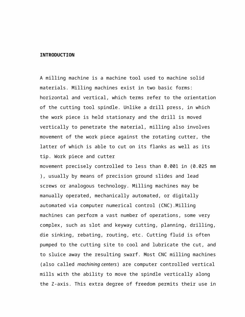
A milling machine is a machine tool used to machine solid materials. Milling machines
exist in two basic forms: horizontal and vertical, which terms refer to the orientation of the
cutting tool spindle. Unlike a drill press, in which the work piece is held stationary and the
drill is moved vertically to penetrate the material, milling also involves movement of the
work piece against the rotating cutter, the latter of which is able to cut on its flanks as well
as its tip. Work piece and cutter
movement precisely controlled to less than 0.001 in (0.025 mm), usually by means of precis
ion ground slides and lead screws or analogous technology. Milling machines may be
manually operated, mechanically automated, or digitally automated via computer numerical
control (CNC).Milling machines can perform a vast number of operations, some very
complex, such as slot and keyway cutting, planning, drilling, die sinking, rebating, routing,
etc. Cutting fluid is often pumped to the cutting site to cool and lubricate the cut, and to
sluice away the resulting swarf. Most CNC milling machines (also called machining
centers) are computer controlled vertical mills with the ability to move the spindle
vertically along the Z-axis. This extra degree of freedom permits their use in die sinking,
engraving applications, and 2.5D surfaces such as relief sculptures. When combined with
the use of conical tools or a ball nose cutter, it also significantly improves milling precision
without impacting speed, providing a cost-efficient alternative to most flat-surface hand-
engraving work.
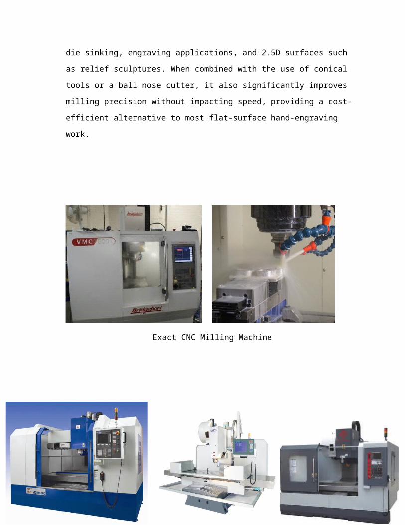
Exact CNC Milling Machine
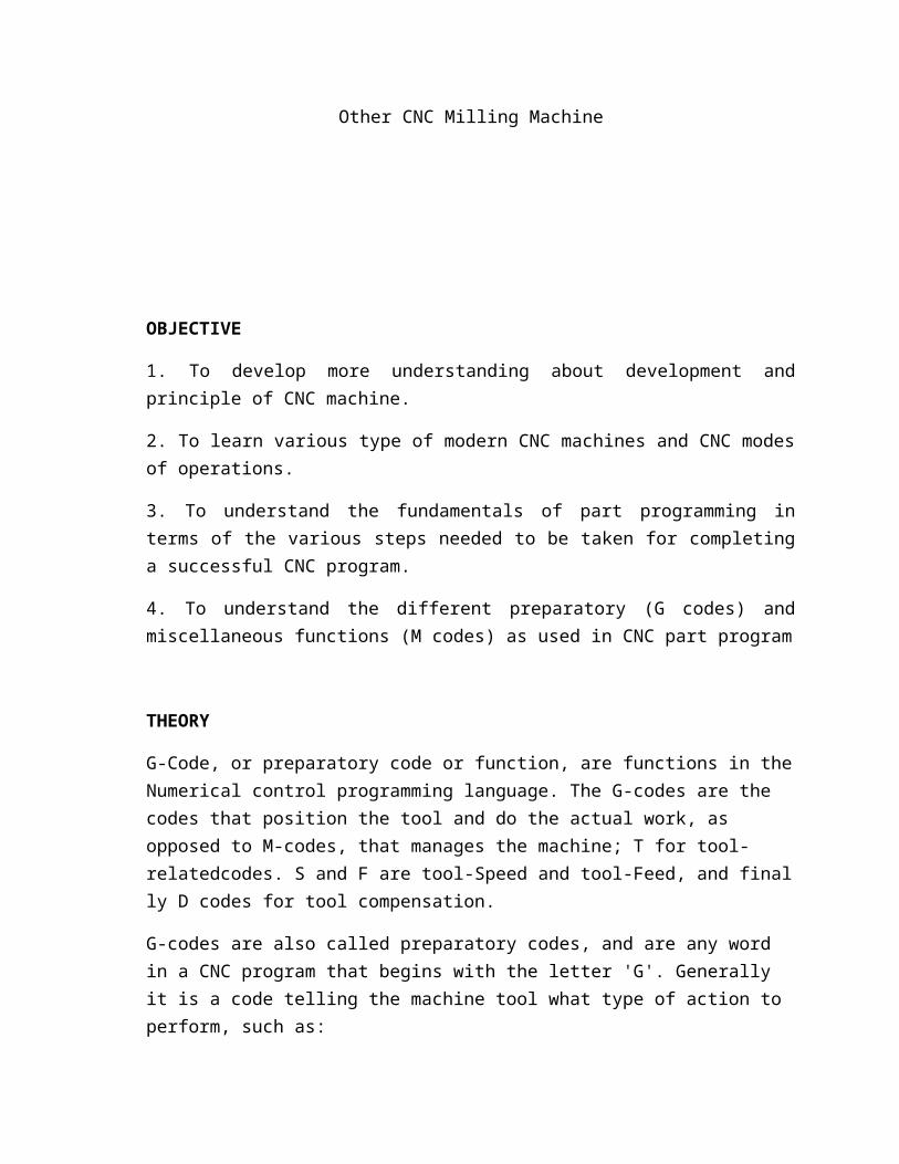
Other CNC Milling Machine
OBJECTIVE
1. To develop more understanding about development and principle of CNC machine.
2. To learn various type of modern CNC machines and CNC modes of operations.
3. To understand the fundamentals of part programming in terms of the various steps needed to be taken for completing a successful CNC program.
4. To understand the different preparatory (G codes) and miscellaneous functions (M codes) as used in CNC part program
THEORY
G-Code, or preparatory code or function, are functions in the Numerical control programming language. The G-codes are the codes that position the tool and do the actual work, as opposed to M-codes, that manages the machine; T for tool-relatedcodes. S and F are tool-Speed and tool-Feed, and finally D codes for tool compensation.
G-codes are also called preparatory codes, and are any word in a CNC program that begins with the letter 'G'. Generally it is a code telling the machine tool what type of action to perform, such as:
Rapid move Controlled feed move in a straight line or arc Series of controlled feed moves that would result in a hole being bored, a workpiece
cut (routed) to a specific dimension. change a pallet Set tool information such as offset.
There are other codes; the type codes can be thought of like registers in a computer
X = Absolute position
Y = Absolute position
Z = Absolute position
M = Referred to as a "Miscellaneous" function
F = Feed rate
S = Spindle speed
N = Line number
R = Arc radius or optional word passed to a subprogram/canned cycle
M codes
Controls the overall machine, causing it to stop, start, turn on coolant, etc., whereas other codes pertain to the path traversed by cutting tools. Different machine tools may use the same code to perform different functions; even machines that use the same CNC control.
Partial list of M-Codes• M00 = Program Stop (non-optional)• M01 = Optional Stop, machine will only stop if operator selects this option• M02 = End of Program• M03 = Spindle on (CW rotation)• M04 = Spindle on (CCW rotation)• M05 = Spindle Stop• M06 = Tool Change• M07 = Coolant on (flood)• M08 = Coolant on (mist)• M09 = Coolant off • M10 = Pallet clamp on• M11 = Pallet clamp off • M30 = End of program/rewind tape (required for older CNC machines)
Common FANUC G Codes for Mill

• G00 = Rapid positioning• G01 = Linear interpolation• G02 = Clockwise circular interpolation• G03 = Counter Clockwise circular interpolation• G90 = Absolute programming (type B and C systems)• G91 = Incremental programming (type B and C systems)
SAFETY
When the student at the workshop, the safety is mainly advised so that any mistakes happen. It’s make the student to be more safe even independent too.
They should wear workshop uniform and safety boots which given by the polytechnic.
Gloves are advised to be wear before holding and after all work done it should be removed.
Place the matrix card on the pocket of workshop uniforms when handling with machines.
Students should not play or joke around the machines which could harm them.
Safety boots

Workshop uniform
PROCEDURE OF PROJECT
Steps Involved in SIMULATION by using (EXCL WIN 7)
1. Program of EXCL WIN 7 is clicked.
2. Then Project is clicked once it’s fully loaded.
3. Management is chosen and then New Project.
4. Choose Project Name : Example (HaRThi)
5. Then Fanuc OTC is clicked from the entire list, click Apply
once done.
6. The common code such as M Code and G Code is typed from the beginning until the end.
7. Once done, its Save As (Using Same Programme Number: O0001;)
8. Once save, chose Edit on the right hand side of the program.
9. Then select Empty Tool Changer.
10. Select Changer 24 and click Load.
11. Select the most suitable tools (Example: End Mill d : 3mm)
12. Click to insert the tool in the correct T
13. Click Corrections, then Measure and Close.
14. Blank is clicked select The Blank Profile : Square Bar
15. Insert the value of work piece from its Length, width and height and click OK.
16. Zero Reference Point is clicked and its Origin is stated.
17. Once all done, Select Simulation and then Full Sequence to view your work piece with its project on it.
Steps Involved in CUTTING process by using BRIDGEPORTVMX 600X
1. All of the instrument such as milling cutter (cutting tool), work piece and needed material with its tools are placed.
2. Main switch of power is switched on.
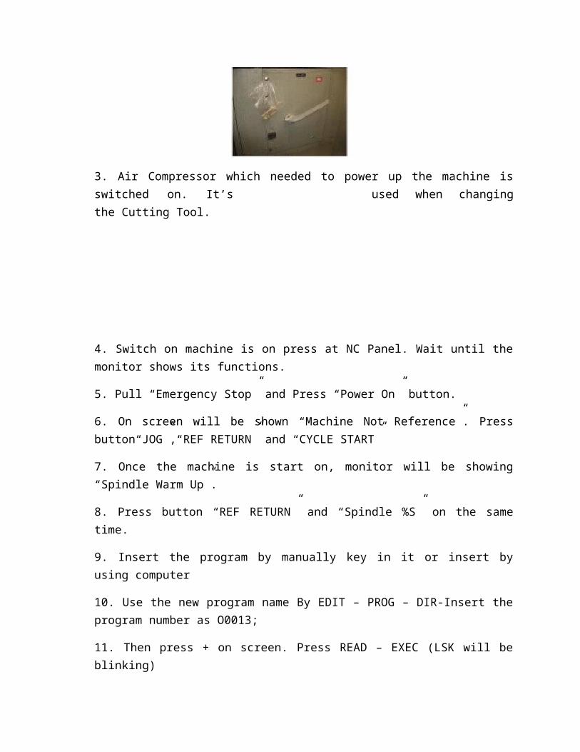
3. Air Compressor which needed to power up the machine is switched on. It’s used when changing the Cutting Tool.
4. Switch on machine is on press at NC Panel. Wait until the monitor shows its functions.
5. Pull “Emergency Stop” and Press “Power On” button.
6. On screen will be shown “Machine Not Reference”. Press button“JOG”,“REF RETURN” and “CYCLE START”
7. Once the machine is start on, monitor will be showing “Spindle Warm Up”.
8. Press button “REF RETURN” and “Spindle %S” on the same time.
9. Insert the program by manually key in it or insert by using computer
10. Use the new program name By EDIT – PROG – DIR-Insert the program number as O0013;
11. Then press + on screen. Press READ – EXEC (LSK will be blinking)
12. On computer, make sure it’s at EDIT – DATA TRANSFER – choose FILE NAME
of the program which insert and press START.
13.For work piece setting, press “ HANDLE” for using “hand wheel” to manually movement.
14. Bring the pointer to the work piece on the coordinate of Z. Press “WORKSHIFT”.
Take the reading, example -467.018 and radius 2.000.
15. Adjust the coordinate of X by bringing the milling cutter towards the work piece. Press
“WORKSHIFT”. Take the reading, example -467.018 and the radius2.000 is been minus. It does enter on the place of G54.
16. Repeat the steps 10 for Y coordinates.
17. To see the coordinate X, Y and Z, bring the milling cutter(cutting tool) to the work piece by using “hand wheel”.
18. Once you are confidence of its coordinate ORIGIN and press “POS”,
and then click X. X will be blinking and press ORIGIN.
19. Repeat the steps of 15 for Y and Z.
20. “PROG”
21. “AUTO” “CYCLE START”.
22. Cutting process will start on.
23. Close the machine once the work piece is taken out and clean up the machine before close it.
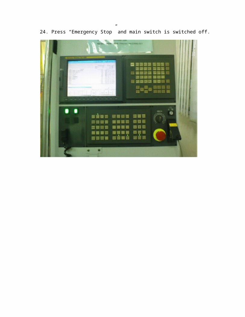
24. Press “Emergency Stop” and main switch is switched off.
ATTACHMENTS
CONCLUSION
In conclusion, the objectives of the workshop practice are achieved. Students are more confidences and comfortable using the CNC milling machines using the G-codes and M-codes.
REFERENCE
1. Web Sites
• http://www.ehow.com/facts_4830778 -cnc-machines.html
• http://www.technologystudent.com/cam/cncman4.htm
•http://en.wikipedia.org/wiki/Milling_machine
•http://en.wikipedia.org/wiki/G-code
•http://en.wikipedia.org/wiki/Milling_cutter#Features_of_a_milling_cutter
2. Books
• Teknologi Worksyop – Abdul Rahman Darman
3. Lecturer
• En.Mohamad Hazizan Bin Atan