cms tracker optical control link specification part 1:...
TRANSCRIPT

CMS Tracker Optical Control Link Specification
Part 1: System
Version 1.2, 7th March, 2003.
CERN EP/CME
Preliminary
Document ID: CMS-TK-ES-0018

Document ID: CMS-TK-ES-0018
1
1. INTRODUCTION ..................................................................................................................................................2
1.1. GENERAL SYSTEM DESCRIPTION..................................................................................................................2 1.2. DOCUMENT STRUCTURE AND CONVENTION...............................................................................................3 1.3. RELATED WWW SITES...................................................................................................................................4 1.4. DOCUMENT HISTORY .....................................................................................................................................4 1.5. CONTACTS.......................................................................................................................................................4
2. TECHNICAL REQUIREMENT, PART 1: SYSTEM........................................................................................5
2.1. DESCRIPTION...................................................................................................................................................5 2.2. BLOCK DIAGRAM............................................................................................................................................5 2.3. TARGET SPECIFICATIONS (@25°C UNLESS OTHERWISE NOTED)..............................................................6 2.4. OPERATING ENVIRONMENT ..........................................................................................................................8 2.5. OTHER CHARACTERISTICS ............................................................................................................................9 2.6. TESTING.........................................................................................................................................................10 2.7. IMPLEMENTATION ........................................................................................................................................11
3. GLOSSARY ..........................................................................................................................................................12
3.1. SKEW..............................................................................................................................................................12 3.2. JITTER ............................................................................................................................................................12
4. REFERENCES .....................................................................................................................................................13
1. Introduction
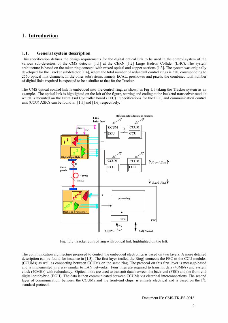
1.1. General system description This specification defines the design requirements for the digital optical link to be used in the control system of the various sub-detectors of the CMS detector [1.1] at the CERN [1.2] Large Hadron Collider (LHC). The system architecture is based on the token ring concept, with mixed optical and copper sections [1.3]. The system was originally developed for the Tracker subdetector [1.4], where the total number of redundant control rings is 320, corresponding to 2560 optical link channels. In the other subsystems, namely ECAL, preshower and pixels, the combined total number of digital links required is expected to be a similar to that for the Tracker. The CMS optical control link is embedded into the control ring, as shown in Fig 1.1 taking the Tracker system as an example. The optical link is highlighted on the left of the figure, starting and ending at the backend transceiver module which is mounted on the Front End Controller board (FEC). Specifications for the FEC, and communication control unit (CCU) ASICs can be found in [1.5] and [1.6] respectively.
Front End
Back End
~ 100m
processing
TIMING
TTC FEC
LinkInterface
I2C channels to front-end modules
I2C
12
DAQ Control
8 x 12
Patch panels
Reset
Back-end Transceiver
CCU4CCUM
Digital Opto HybridDigital Opto Hybrid
CCU
CCUM
CCU CCU
CCUM CCUM
Fig. 1.1. Tracker control ring with optical link highlighted on the left. The communication architecture proposed to control the embedded electronics is based on two layers. A more detailed description can be found for instance in [1.3]. The first layer (called the Ring) connects the FEC to the CCU modules (CCUMs) as well as connecting between CCUMs on the same ring. The protocol on this first layer is message-based and is implemented in a way similar to LAN networks. Four lines are required to transmit data (40Mb/s) and system clock (40MHz) with redundancy. Optical links are used to transmit data between the back-end (FEC) and the front-end digital optohybrid (DOH). The data is then communicated between CCUMs via electrical interconnections. The second layer of communication, between the CCUMs and the front-end chips, is entirely electrical and is based on the I2C standard protocol.
Document ID: CMS-TK-ES-0018
2
Document ID: CMS-TK-ES-0018
3
1.2. Document structure and convention The optical link specification is broken down into eight independent parts, each describing and specifying a different level or function in the system:
Part 1. System Part 2. Digital Opto-Hybrid 2.1 Laser Driver ASIC
2.2 Laser Transmitter 2.2.1 Terminated Pigtail
2.2.1.1 Buffered Fibre 2.3 PIN Photodiode 2.4 Digital Receiver ASIC 2.5 Digital Optohybrid Substrate
Part 3. Terminated Fibre Ribbon
3.1 Ruggedized Ribbon Harness 3.1.1 Ruggedized Ribbon
Part 4. Terminated Multi-Ribbon Cable
4.1 Dense Multi-Ribbon Cable Part 5. Back-End Opto-Transceiver Module Part 6. Distributed Patch Panel 6.1 MU-sMU Adaptor Part 7. In Line Patch Panel
7.1 MFS Adaptor Part 8. Backend Patch Panel
8.1 Connector Shell
Each part has the following structure: 1. Introduction 1.1. System description 1.2. Document structure 1.3. Related WWW sites 1.4. Contact 1.5. Document history
2. Technical requirement 2.1. description 2.2. block diagram 2.3. specification 2.4. operating environment 2.5. other characteristics 2.6. testing 2.7. implementation
3. Glossary 4. References
Due to the preliminary nature of this document, the specification section (section 2.3) of each system part is labelled "target specifications". CERN should be consulted before any hardware or software relying on these characteristics is being designed. Target specifications will eventually evolve into full specifications once the system definition is mature. Parameters still to be determined are labelled TBD.

1.3. Related WWW sites CERN laboratory: http://www.cern.ch/Public/ CMS project: http://cmsinfo.cern.ch/Welcome.html CMS Tracker Technical Design Report: http://cmsdoc.cern.ch/ftp/TDR/TRACKER/tracker.html CMS Tracker Electronic System: http://cmstrackercontrol.web.cern.ch/CMSTrackerControl/docmain.htm CMS Tracker Optical Links: http://cms-tk-opto.web.cern.ch/ FED developments: http://www.te.rl.ac.uk/esdg/cms_fed_pmc/index.html APV and MUX developments: http://www.te.rl.ac.uk/med/
1.4. Document history
Rev. 1.0, 17/12/02 Draft (KG) Rev. 1.1, 24/1/03 Propagated changes from DOH and TRx specs. Power margins added.(KG) Rev. 1.2, 7/3/03 Modified output termination based on TRx specs.(KG)
1.5. Contacts
All questions regarding this document should be addressed to: F. Vasey EP Division CERN CH-1211 Geneva 23 Fax: +41 22 767 2800 Phone +41 22 767 3885 E-mail [email protected]
K. Gill EP Division CERN CH-1211 Geneva 23 Fax: +41 22 767 2800 Phone +41 22 767 8583 E-mail [email protected]
Document ID: CMS-TK-ES-0018

2. Technical requirement, part 1: system
2.1. Description On the front-end DOH, labelled (1) in Fig. 2.1, the lasers are 1310nm InGaAsP/InP edge-emitters, pigtailed with
single-mode 9/125/250/900µm fibre that is terminated with an MU connector. The receivers on the DOH are InGaAs/InP p-i-n photodiodes pigtailed in the same way as the lasers. Also mounted on the DOH are the LLD laser driver ASIC, and the RX40 receiver ASIC.
After the distributed patch panel (5), which houses MU-sMU connections, the fibres attached to components on a given DOH (and its redundant back-up DOH) are then fanned into a 12-way ruggedized ribbon cable (2) using a compact fan-in element. In each ribbon there are 4 fibres transmitting light to the Tracker, 4 dark fibres, and 4 fibres transmitting light from the Tracker. The 12-fibre modularity matches that of the fibre-ribbon components used in the analogue readout link system at the relatively small expense of the additional dark fibre.
The optical cables follow the same routing (in the Tracker) as for the readout links and will share the same in-line patch panels (6), using MFS connectors. Groups of eight ribbons are then fanned into 96-way dense multi-ribbon cables (3), which then pass to the counting room.
At the back-end of the links in the counting room, 4+4 way transceiver modules (4), each having a 12-way MPO optical interface (7), will be mounted on the FEC.
Altogether, 2560 optical readout channels (optical fibres) will be implemented for control of the CMS Tracker and a similar, perhaps greater number is expected to be required for the other CMS sub-systems, including ECAL, Preshower and Pixels.
2.2. Block diagram
Front-end Digital Optohybrid (DOH)
12 96
~1m
~5m ~60mTo/fromCCUMs to/from
FEC
PatchPanels
1
5
2
6
3
7
Ribboncable
Multi-ribbonCable
I2C
Backend TransceiverModule (TRx)
4
Reset
Single-wayfibres
1
1
Fan-in
Fig. 2.1. Optical link block diagram
Document ID: CMS-TK-ES-0018
5

Document ID: CMS-TK-ES-0018
6
2.3. Target Specifications (@25°C unless otherwise noted)
# operational specifications
min typ max unit note
1.1 Total length 60 m 1.2 Bit Rate 2 80 Mb/s Balanced code 1.3 Bit Error Rate 10-12 10-9 1.4 Skew 2 ns Between any 2 fibres coming from
the same hybrid, see glossary 3.1 1.5 Jitter 0.5 ns rms, see glossary 3.2 1.6 Operation rate 4000 hrs/year
specs 1.7 to 1.10 reserved for future use
# Front-end electrical specifications
min typ max unit note
1.11 Differential input voltage ±300 mV Into 120Ω. Note that the LLD
ASIC has an analogue transfer characteristic.
1.12 Input impedance 120 Ω 1.13 Differential output voltage ±250 ±400 mV LVDS.
Should be terminated differentially with 100Ω.
1.14 Reset Output Active low Generated by RX40 upon reception of 10 consecutive ‘0’ levels on Data channel at DOH.
1.15 Reset action at front-end DOH
A reset is generated at LLD at power-up or when RX40 outputs a reset. Sets transmitter quiescent operating point to hard-wired start-up settings (spec 1.19)
1.16 Power supply 2.25 2.7 V 1.17 Power dissipation 350 mW Per DOH worst-case (i.e. half
control ring) 1.18 I2C address 11100 Fixed 1.19 Default LLD laser I2C bias
setting X1X2X30000 Where X1X2X3 = 011 = 48decimal
(TBD). Approximately 22mA. Value is selected during production.
1.20 Default LLD gain setting 12.5 mS Hard-wired in LLD 1.21 Electrical connector 26-way male NAIS See fig. 2.2 and Table 2.1 for
connector pin assignment. Specs 1.22 to 1.30 Reserved for future use
Document ID: CMS-TK-ES-0018
7
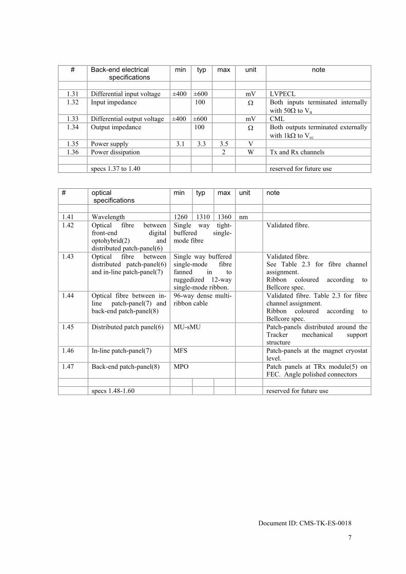
# Back-end electrical
specifications min typ max unit note
1.31 Differential input voltage ±400 ±600 mV LVPECL 1.32 Input impedance 100 Ω Both inputs terminated internally
with 50Ω to Vtt 1.33 Differential output voltage ±400 ±600 mV CML 1.34 Output impedance 100 Ω Both outputs terminated externally
with 1kΩ to Vcc 1.35 Power supply 3.1 3.3 3.5 V 1.36 Power dissipation 2 W Tx and Rx channels
specs 1.37 to 1.40 reserved for future use
# optical
specifications min typ max unit note
1.41 Wavelength 1260 1310 1360 nm 1.42 Optical fibre between
front-end digital optohybrid(2) and distributed patch-panel(6)
Single way tight- buffered single-mode fibre
Validated fibre.
1.43 Optical fibre between distributed patch-panel(6) and in-line patch-panel(7)
Single way buffered single-mode fibre fanned in to ruggedized 12-way single-mode ribbon.
Validated fibre. See Table 2.3 for fibre channel assignment. Ribbon coloured according to Bellcore spec.
1.44 Optical fibre between in-line patch-panel(7) and back-end patch-panel(8)
96-way dense multi-ribbon cable
Validated fibre. Table 2.3 for fibre channel assignment. Ribbon coloured according to Bellcore spec.
1.45 Distributed patch panel(6) MU-sMU Patch-panels distributed around the Tracker mechanical support structure
1.46 In-line patch-panel(7) MFS Patch-panels at the magnet cryostat level.
1.47 Back-end patch-panel(8) MPO Patch panels at TRx module(5) on FEC. Angle polished connectors
specs 1.48-1.60 reserved for future use
Document ID: CMS-TK-ES-0018
8
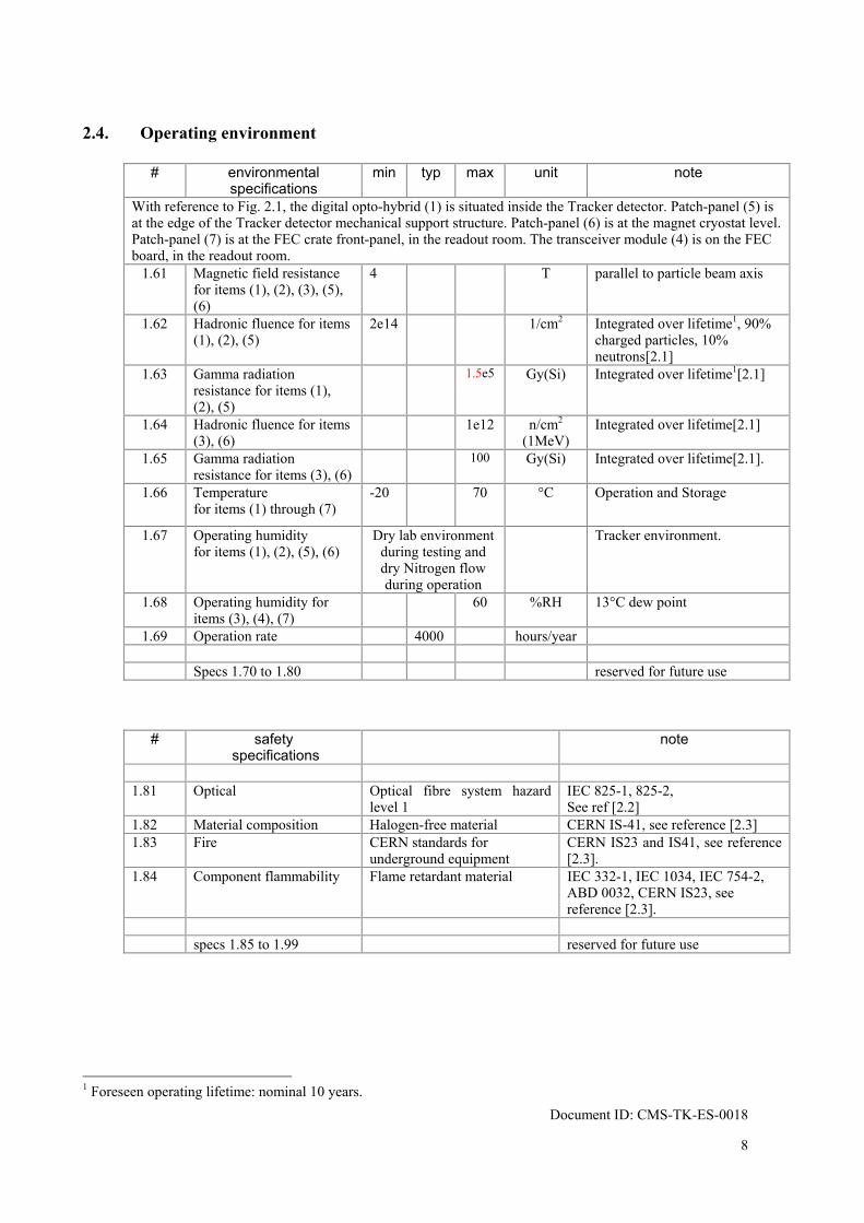
2.4. Operating environment
# environmental specifications
min typ max unit note
With reference to Fig. 2.1, the digital opto-hybrid (1) is situated inside the Tracker detector. Patch-panel (5) is at the edge of the Tracker detector mechanical support structure. Patch-panel (6) is at the magnet cryostat level. Patch-panel (7) is at the FEC crate front-panel, in the readout room. The transceiver module (4) is on the FEC board, in the readout room.
1.61 Magnetic field resistance for items (1), (2), (3), (5), (6)
4 T parallel to particle beam axis
1.62 Hadronic fluence for items (1), (2), (5)
2e14 1/cm2 Integrated over lifetime1, 90% charged particles, 10% neutrons[2.1]
1.63 Gamma radiation resistance for items (1), (2), (5)
1.5e5 Gy(Si) Integrated over lifetime1[2.1]
1.64 Hadronic fluence for items (3), (6)
1e12 n/cm2 (1MeV)
Integrated over lifetime[2.1]
1.65 Gamma radiation resistance for items (3), (6)
100 Gy(Si) Integrated over lifetime[2.1].
1.66 Temperature for items (1) through (7)
-20 70 °C Operation and Storage
1.67 Operating humidity for items (1), (2), (5), (6)
Dry lab environment during testing and dry Nitrogen flow during operation
Tracker environment.
1.68 Operating humidity for items (3), (4), (7)
60 %RH 13°C dew point
1.69 Operation rate 4000 hours/year Specs 1.70 to 1.80 reserved for future use
# safety specifications
note
1.81 Optical Optical fibre system hazard
level 1 IEC 825-1, 825-2, See ref [2.2]
1.82 Material composition Halogen-free material CERN IS-41, see reference [2.3] 1.83 Fire CERN standards for
underground equipment CERN IS23 and IS41, see reference [2.3].
1.84 Component flammability Flame retardant material IEC 332-1, IEC 1034, IEC 754-2, ABD 0032, CERN IS23, see reference [2.3].
specs 1.85 to 1.99 reserved for future use
1 Foreseen operating lifetime: nominal 10 years.
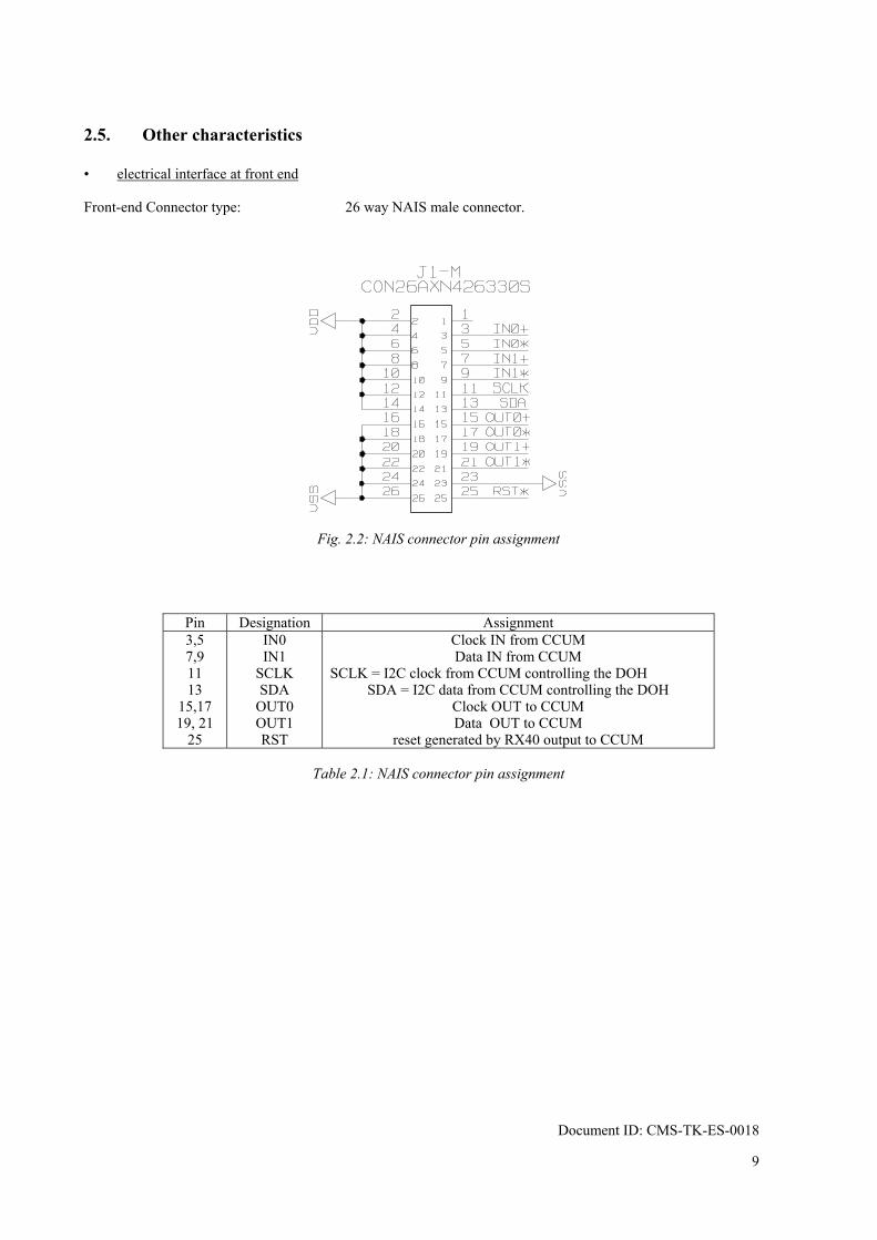
2.5. Other characteristics • electrical interface at front end Front-end Connector type: 26 way NAIS male connector.
Fig. 2.2: NAIS connector pin assignment
Pin Designation Assignment 3,5 7,9 11 13
15,17 19, 21
25
IN0 IN1
SCLK SDA
OUT0 OUT1 RST
Clock IN from CCUM Data IN from CCUM
SCLK = I2C clock from CCUM controlling the DOH SDA = I2C data from CCUM controlling the DOH
Clock OUT to CCUM Data OUT to CCUM
reset generated by RX40 output to CCUM
Table 2.1: NAIS connector pin assignment
Document ID: CMS-TK-ES-0018
9

Document ID: CMS-TK-ES-0018
10
• electrical interface at back-end TRx: Surface mount leadframe, to be soldered on FEC board. External termination resistors on output lines. Module and pin-out TBD (see Table 2.2)
Designation
Pin number
Fibre number in
ribbon (preliminary)
Assignment
CK in A DA in A CK in B DA in B
CK out A DA out A CK out B DA out B
TBD TBD TBD TBD TBD TBD TBD TBD
1 2 3 4
12 11 10 9
CK (from FEC to CCUM ring A) DA (from FEC to CCUM ring A) CK (from FEC to CCUM ring B) DA (from FEC to CCUM ring B) CK (from CCUM ring A to FEC) DA (from CCUM ring A to FEC) CK (from CCUM ring B to FEC) DA (from CCUM ring B to FEC)
Table 2.2: Backend module pin assignment
• Optical fibre-ribbon channel assignment (preliminary)
Channel
Assignment
1 2 3 4 5 6 7 8 9
10 11 12
CK (from FEC to CCUM ring A) DA (from FEC to CCUM ring A) CK (from FEC to CCUM ring B) DA (from FEC to CCUM ring B)
Dark Dark Dark Dark
DA (from CCUM ring B to FEC) CK (from CCUM ring B to FEC) DA (from CCUM ring A to FEC) CK (from CCUM ring A to FEC)
Table 2.3: Fibre ribbon channel assignment.
2.6. Testing Final in-system testing procedure TBD.

2.7. Implementation The system implementation with components as specified provides the following optical power budget figures: (a) For the DOH to TRx links, from front-end to FEC:
-30
-25
-20
-15
-10
-5
0
DOH
Tx s
igna
l am
plitu
de (d
Bm)
-15 -10 -5 0TRx Rx saturation (dBm)
-30
-25
-20
-15
-10
-5
0
TRx Rx sensitivity (dBm)
-15 -10 -5 0
DOH Tx average launched power (dBm)
TRx responsivity
TRx
satu
ratio
n
Tx min OMA
Tx m
ax a
ve la
unch
pow
er
MU-sMU and MFS patch panelsDOH Tx with 0.016uW/mA
DOH to TRx links
(b) For the TRx to DOH links, from FEC to the front-end:
-30
-25
-20
-15
-10
-5
0
TRx
Tx s
igna
l am
plitu
de (d
Bm)
-15 -10 -5 0DOH Rx saturation (dBm)
-30
-25
-20
-15
-10
-5
0
DO
H R
x sensitivity (dBm)
-15 -10 -5 0TRx Tx average launched power (dBm)
Rx40 sensitivity
Rx4
0 sa
tura
tion
TRx
max
ave
laun
ch p
ower
TRx min OMA
TRx with MFS and MU-sMU patch-panels
TRx to DOH links
Document ID: CMS-TK-ES-0018
11

3. Glossary
3.1. Skew
The skew is determined by measuring, for two channels, the average time t50 required for a step response signal to reach 50% of its end value. The skew between channels i and j is defined as:
tskew = t50, j– t50,i
3.2. Jitter
The rms jitter is defined as the rms deviation of the time t50 required for a step response signal to reach 50% of its end value:
25050jitter )t-(tt =
Document ID: CMS-TK-ES-0018
12

Document ID: CMS-TK-ES-0018
13
4. References [1.1] http://cmsinfo.cern.ch/cmsinfo/Welcome.html [1.2] http://www.cern.ch/ [1.3] A. Marchioro, " Specifications for the control electronics of the CMS Inner Tracker", Draft V2, CERN [1.4] The tracker project, technical design report, CERN/LHCC 98-6 [1.5] A. Marchioro, "FEC specification", Draft, CERN [1.6] A. Marchioro, "CCU specification", Draft, CERN
[2.1] M. Huhtinen, “Studies of neutron moderator configurations around the CMS inner tracker and Ecal”, CERN
CMS TN/96-057, 1996. [2.2] K. Gill, “Laser safety in the CMS Tracker optical links”, http://edms.cern.ch/document/338505/1. [2.3] http://www.cern.ch/CERN/Divisions/TIS/safdoc/instr_en.html