cmm justification cmm a short history · cmm justification the ... least was operator error and...
TRANSCRIPT

CMM Justification
The following was researched for assisting those individuals interested in acquiring a Coordinate Measurement Machine (CMM). All data referenced is available for the asking. Extracts from trade journals and sales literature are too numerous to fax or send via PDF. The file is THICK, having been updated over the decades that I have been in this business. - Mike Bingham, Oct 2003.
CMM – a short history
It is a majority of opinion that Ferranti Limited, a division of the largest DOD contractor in the United Kingdom, introduced the CMM at the International Machine Show in Paris, 1959. Sheffield imported this cmm into the U.S.A. until 1963 when they introduced the Cordax CMM. Since then, every major gage manufacturer has manufactured, distributed or provided accessories for CMMs.
Manual CMM
The traditional CMM is a machine that is constructed of precision guide ways mounted in such a way as to permit a measuring probe move in XYZ direction in order to contact the part to be inspected. Digital readout for each axis resolves to .0001” or finer resolution. In the 1960’s, this was revolutionary since technology at the time was a granite surface plate and a height stand. The inspector had to build up a stack of gage blocks to nominal (exact part print dimension) height, zero out the dial indicator attached to the height stand and transfer the stand to the production part to be inspected. This was labor intensive and subject to numerous errors (none the least was operator error and sever build up of tolerance). By the way, the gage makes “Rule of Ten” introduced pre- WW2 was an attempt to eliminate the random measurement errors that plagued these “ open setup” inspection procedures.
Many Benefits of having a CMM…However?
A cmm is flexible, can check much different size parts, eliminates human error, can generate voluminous data, reports and SPC charts. CMMs automates data collection for evaluating a process capability. This saves money and time and eliminates the human error/influence in data gathering and input. Purchasing a CMM allows for the reduction / elimination of special gages and tooling that might need to be purchased / built, maintained and calibrated. Auto alignment features in the cmm software helps eliminate/reduce error in fixture builds, tool wear, operator error when loading a part. CMMs can be bridge type, cantilever or horizontal arm in design. They may have air bearings, precision hard bearing or porous media bearings. Everything I have said is a feature that distinguishes one CMM manufacture from another. Nothing I have said so far will get a second glance from the Finance Department. We need to JUSTIFY the purchase of a CMM based upon COST SAVINGS. Traditional Return on Investment (ROI) accounting methods will not work because a cmm can not be directly linked to part production estimates of payback. CMM manufacturers know this and have conducted application studies and have developed a logical method of ROI that usually gets the approval for purchase. Since I can not be in the room to present this ROI, it will be up to you to SELL the NEED for a CMM, justify the purchase of it and show the benefits of the CMM over the current method of inspection. If you can do this, you get the cmm!

What are the Economic Advantages of a CMM
Why buy a CMM when we been doing just fine for years with the present method. If it ain’t broke, don’t fix it. I could send pages on this one but we must face the fact that unless we can successfully answer this question, we will not get past first base.
You need a CMM to SAVE MONEY!
CMMs save money by reducing Inspection Costs
CMMs save money by reducing Scrap and Rework
CMMs save money by reducing down time waiting for inspection results
From various application studies, manual CMMs inspect parts at least 10 times faster than surface plate methods. This has been documented over 40 years! It is a fact.
Cost Reduction in Inspection (Manual CMM)
Current inspection method vs. Manual CMM
Inspection time per part Savings/part
Current method 50 minutes
Manual CMM 5 minutes 45 minutes
Per year savings parts per year minutes saved per year hours saved per year
45 Minutes x 5,000 = 225,000 60 min per hour = 3,750 hours
Savings/year Cost of inspection per hour Annual Insp. savings
3,750 hours x $ 50.00 = $ 187,500.00
Cost Reduction in Downtime
Improving utilization is directly proportional to decreased inspection time. Down time is machine tool idle time waiting for inspection results. First piece inspection time reduction (typically time is reduced by 25%) increases output though out the manufacturing process.
Annual downtime (hours)
Current method 800 hours
Manual CMM 450 hours
Savings 350 hrs. x $ 50.00 (downtime/hr) = $ 10,500 savings/year
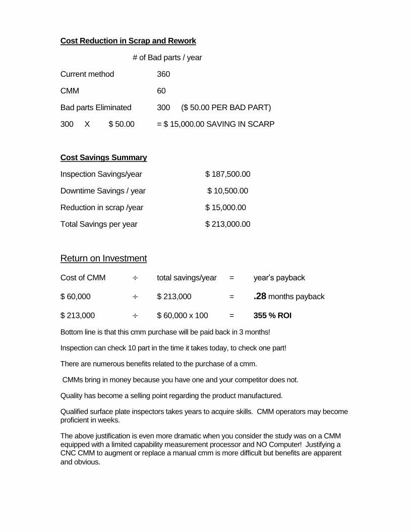
Cost Reduction in Scrap and Rework
# of Bad parts / year
Current method 360
CMM 60
Bad parts Eliminated 300 ($ 50.00 PER BAD PART)
300 X $ 50.00 = $ 15,000.00 SAVING IN SCARP
Cost Savings Summary
Inspection Savings/year $ 187,500.00
Downtime Savings / year $ 10,500.00
Reduction in scrap /year $ 15,000.00
Total Savings per year $ 213,000.00
Return on Investment
Cost of CMM total savings/year = year’s payback
$ 60,000 $ 213,000 = .28 months payback
$ 213,000 $ 60,000 x 100 = 355 % ROI
Bottom line is that this cmm purchase will be paid back in 3 months!
Inspection can check 10 part in the time it takes today, to check one part!
There are numerous benefits related to the purchase of a cmm.
CMMs bring in money because you have one and your competitor does not.
Quality has become a selling point regarding the product manufactured.
Qualified surface plate inspectors takes years to acquire skills. CMM operators may become proficient in weeks.
The above justification is even more dramatic when you consider the study was on a CMM equipped with a limited capability measurement processor and NO Computer! Justifying a CNC CMM to augment or replace a manual cmm is more difficult but benefits are apparent
and obvious.
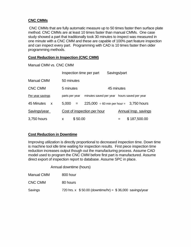
CNC CMMs
CNC CMMs that are fully automatic measure up to 50 times faster then surface plate method. CNC CMMs are at least 10 times faster than manual CMMs. One case study showed a part that traditionally took 30 minutes to inspect was measured in one minute with a CNC CMM and these are capable of 100% part feature inspection and can inspect every part. Programming with CAD is 10 times faster then older programming methods.
Cost Reduction in Inspection (CNC CMM)
Manual CMM vs. CNC CMM
Inspection time per part Savings/part
Manual CMM 50 minutes
CNC CMM 5 minutes 45 minutes
Per year savings parts per year minutes saved per year hours saved per year
45 Minutes x 5,000 = 225,000 60 min per hour = 3,750 hours
Savings/year Cost of inspection per hour Annual Insp. savings
3,750 hours x $ 50.00 = $ 187,500.00
Cost Reduction in Downtime
Improving utilization is directly proportional to decreased inspection time. Down time is machine tool idle time waiting for inspection results. First piece inspection time reduction increases output though out the manufacturing process. Assume CAD model used to program the CNC CMM before first part is manufactured. Assume direct export of inspection report to database. Assume SPC in place.
Annual downtime (hours)
Manual CMM 800 hour
CNC CMM 80 hours
Savings 720 hrs. x $ 50.00 (downtime/hr) = $ 36,000 savings/year

Cost Reduction in Scrap and Rework
# of Bad parts / year
Current method 60
CMM 6
Bad parts Eliminated 54 ($ 50.00 PER BAD PART)
54 X $ 50.00 = $ 2,700.00 SAVING IN SCARP
Cost Savings Summary
Inspection Savings/year $ 187,500.00
Downtime Savings / year $ 36,000.00
Reduction in scrap /year $ 2,700.00
Total Savings per year $ 226,200.00
Return on Investment
Cost of CMM total savings/year = year’s payback
$ 100,000 $ 226,200 = .44 months payback
$ 226,200 $ 100,000 x 100 = 226 % ROI
Bottom line is that this cmm purchase will be paid back in 5 months!
Inspection can check 10 part in the time it takes today, to check one part!
Sizing the CMM Cube
Once you have decided to purchase a cmm, the first thing to consider is size. CMMs were developed around the size of the part that could be machined on a Bridgeport Mill. Today, most CMMs are sized in Millimeters…i.e. 7.10.5 is 700mm by one meter (39.37 inches) and 500 mm maximum part height. Here is the tricky part. Not all CMMs specs read the same. A Brown & Sharpe 765 really has 750mm X-axis measuring range. Sheffield’s 9.9.7 can measure 914mm in X an d Y and only 660mm in Z even though it can accept a part 824 mm tall?
When looking at CMMs make sure the CMM with PROBE and PROBE HEAD can measure the MAXIMUM size part that you must measure. This is not readily apparent when reading manufacturers specifications. Manual CMMs have fixed probe heads and touch probes requiring the operator to stop measuring a part,

reorient the touch probe and recalibrate if the part needs to be probed at a different angle. CNC CMMs have motorized probe heads that eliminate this time consuming operation.
PH-1 Probe head and TP-20 Touch probe (manual CMM)
Reputable makers of CMMs specify their CMM measuring range to INCLUDE the motorized probe head. In other words…with the Z axis extended to the table, with the motorized probe head vertical, there still is 30mm of daylight between the probe and granite…you must subtract the length of the TP-20 touch probe (38mm or 1.5 inch) and the length of the stylus to be used, from the stated Z axis, to determine maximum part height.
TP-20 or TP-2 touch probe is 1.5" long. Assume we add 1 inch for the stylus. Now, when the PH10-T is articulated at right angle to the part; subtract 2.5 inches from each side. That is to say, PH10-T at 90 degrees removes 2.5" travel on one side and 2.5" from opposite side of part. This effectively takes out 5 inch from length and width of part you can inspect. More if you have a longer stylus.
Caution

PH10-M is 117 mm (4.606”) long because of the Autojoint.
The PH10-T is 102 mm (4.015”) long. When the PH10-M probe head is turned 90 degrees, you loose 3" of measuring range. That adds up to loosing 6 inch from length and width of part you must inspect. Unless you are going to use long probe extensions and the auto-change rack, stick with the PH10-T.
It is the shortest length probe and does not have the Autojoint. The probe is the part that makes contact with the work piece and is usually the first thing to break due to wear.
Miscellaneous CMM considerations
Much has been made of CMM structure design. This was a major quibbling point before software became the deciding factor. The other major Marketing battle was the Air Bearing vs. hard bearing debate. For all practical purposes, evolution took care of this controversy. CMM design went the way the automobile did (front engine front wheel drive, front engine rear wheel drive, rear engine rear wheel drive, rear engine front wheel drive circa 1920s). The current design is probably as refined, as hardware will get unless someone finds a new wrinkle not thought of. CMMs are still available in Cantilever, Horizontal Arm and Bridge design. You can still buy them with mechanical hard bearing, air jet or porous media bearings. Today, the bridge /air bearing design is the most popular because of the cost of manufacturing and market demand. With advances in ERROR MAPPING, accuracy has taken a back seat in essential selection criteria.

Cantilever Design
Easy three-side part loading and access, main drawback was Z –Axis corkscrew error when Y-axis is at maximum extension. Droop also a factor. Small (under 750MM) CMMs held accuracy good. These small manual CMMs are much easier to use than same size Bridge CMMs. The bridge gets in the way during part measurement. Not a problem in CNC Models.
Bridge Design
This design is today’s benchmark in the industry. Market demand, ease of manufacture and better-perceived accuracy were factors. Manual CMMs were a little more fatiguing on the operator, especially on CMMs over 1 meter.
Horizontal Arm Design
This design incorporated a rotary table. Had 6
axis of movement, X,Y,Z & W (rotary table) A
and B axis (motorized probe head). This was the only way to measure large, heavy parts,
accurately before the Windows® and Carbon Fiber revolution. Today, only 2-3 percent of
CMMs sold have rotary tables mainly because of Motorized probe head improvements in
ability to access the part.
Small Gantry Design
This design is current way to measure medium size, heavy parts. Does not require expensive foundation. May be relocated to another area or plant.

Large Gantry Design
This design is for very large parts. Part Weight is not a consideration. Some designs require
expensive $100,000 foundations.
Gage Maker’s “ Rule of Ten”
Before the introduction of the Coordinate Measurement Machine, and associated Windows based Software, common methods of measurement were fraught with measurement errors. These may be categorized as the four sources of measurement error; inherent instrument error, observational error, manipulative error and bias. To dramatically reduce these measurement errors, the “ Ten-to-One Rule” was developed. (Circa 1932)
Rule: The instrument must be capable of dividing the tolerance into ten parts.
The Purpose: To eliminate 99% of the instrumentation error of previous steps in measurement.
When Applied: To every step in the measurement sequence until the limit of the available
instrument is reached.
The results: Fewer bad parts accepted and good parts rejected.
This whole concept was to reduce the zone of uncertainty and achieve reliable measurement. Before the Digital Age, this Rule was applied to Vernier Metrology Instruments such as Micrometers, Scales and Calipers. Let us return to the four sources of measurement error discussed above.
Observational Error – This error is all but eliminated with introduction of inexpensive DRO metrology instruments. Errors caused by misreading the lines on a micrometer have been eliminated (within reason) with the DRO device.
Manipulative error – Operator influence during measurement is dramatically reduced when an electrical Touch Probe is used to acquire data. It is still possible to “ crank down” a micrometer barrel when measuring a part, however, this act becomes an intentional event and not an error. When the operator chooses to completely ignore the ratchet screw attached to the micrometer barrel, during the measurement process, error is not random.
Bias – Unconscious influence during measurement used to be a problem. Most precision measurements required several readings, which were averaged. The obvious wrong ones were thrown out. This was an open invitation to bias. Again, the introduction to low cost Digital devices much eliminated these errors.

Instrument error – Common practice says, “the measuring instrument should be ten times as accurate as the part”. What does this really mean? What is the goal? When you finally narrow the requirement, the goal is to limit the amount of instrument error that can creep into the measurement, to one percent. Restated the rule is simply: The instrument should divide the tolerance into ten parts. Note that the rule stated applies only to the precision of the instrument, not the accuracy. This is because the accuracy is derived from the standard. If the standard is not accurate, all is lost. The Fineness of measurement described above relates to Precision of measurement and more directly, the Resolution of the instrument.
Why the Ten to One Ratio – This rule was established in an attempt to ensure that all instrument readings would fall within the zone of uncertainty of the instrument. This simply means that over 99% of all measurement readings would show up on the meter. This was statistically determined based on the 3 Sigma confidence level. All repeat errors or dispersion of readings would appear on the meter or readout device. In the old days, inspectors wanted the dial indicator or gage meter to be able to display the Part Error and the instrument error so that all possible problems were covered. I am sure you can understand the main problem with this as tolerances tighten up. You may be discarding “ bad parts” based upon the error of the instrument.
CMM and the “Rule of Ten”-
If one were to carry the 10 to 1 rule to its extreme, a typical CMM with linear volumetric accuracy of .00025” would only be able to measure parts with 0.0025” tolerance. If the part tolerance is .0005”, then a CMM with accuracy of .000050” would be required along with a $ 250,000 price tag. No one that I know of adheres to the “ Rule of Ten” when discussing CMM’s. Unofficially, and though many conversations with various CMM manufacturers, the “Rule of Four” should be in effect for manual CMMs and the “Rule of Two” should be used for CNC CMMs. Why the discrepancy? Remember that the reason the “Rule of Ten” came about to reduce the operator error introduced during the measurement process. Human error is still possible when using a manual CMM. The Touch Probe has greatly reduced this operator influence and thus, significantly increased Repeatability of measurement. Both factors are multiplied regarding a CNC CMM. About the only human error likely is incorrect programming.
CMM Accuracy
From its introduction until the implementation of ERROR MAPPING, the accuracy of a CMM was measured using a Laser Interferometer. The laser beam was “ bucked” (made parallel) to the X axis and the readings over the entire length were observed. The laser reflector was usually positioned mid axis on the Y and Z-axis. Typical accuracy was stated as Linear accuracy +/- .0002” over X-axis. The procedure was repeated on the Y & Z-axis. With the adoption of the ANSI B89 standard, the Ball Bar was added to measure “ Volumetric accuracy. A ball bar looks like a dumb bell. Two datum balls are attached with a length of bar. One “ ball” is located on a magnetic mount that permits rotation. The other ball is locked at various positions on the CMM and numerous measurements of the ball are made. This method of measurement had several flaws. VDI-VDE 2617 was added in an attempt to qualify measuring uncertainty of the CMM. This standard provides for a 95% confidence interval and evaluates linear accuracy specified as U1 and volumetric accuracy specified as U3. In each case, the specification provides a 95% confidence, which means 5% of the observations can be excluded from the testing data. This means "flyers" are tossed which effectively allowed machine accuracy statements to report better accuracy than could actually be achieved.

Understanding the basics of ISO 10-360-2
The ISO 10-360-2 specification changed all of this recognizing that in practical every day
measurement the cmm use does not have the luxury of excluding "flyers" and generally
users do not even know when flyers are observed. As such the ISO spec requires 100% of
all observations to be included in the evaluation of the cmm.
Under ISO 10-360-2, the machine is evaluated in at least 3 areas. MPEE is
volumetric length measurement utilizing calibrated gage blocks. Ball bars
are not used as their length is arbitrary and only the spheres can be
calibrated. Moreover, the measurement of a sphere employs many points to
resolve the center, which does not represent practical measurement. In
practical measurement, point measurements are taken as required for the
respective part feature with the expectation each point is accurate. There is
no luxury to measure multiple points and resolve (1) one point to be used in
the part feature calculation. Under ISO 10-360-2 discrete single points are measured, bi-
directionally to evaluate length and the MPEE value reports the range of measurements
from seven different positions with five different gage lengths, repeated 3 times. All 105
measurements with their deviation from certified lengths are considered and are provided
as an Uncertainty of measured length.
The next ISO 10-360-2 evaluation is MPEP which is Probing uncertainty.
The machine measures 25 discrete points and is evaluated as 25 individual
radii. The range of radii variation , min to max, is the MPEP value.
The next metric in the new Wenzel LH brochure is MPETHP which is
similar to MPEE however this is achieved by full contact scanning of 4
lines, of which, only one can be a full 360 degree equatorial scan. This evaluation
comes from another ISO evaluation, ISO 10-360-4, and is specific to full contact
scanning. As above the points with in each scan are treated as radii and the range of
radii deviation, min to max, is reported.

What now? Now that manufacturing techniques have reached such a precise level, the main
concern is not that the measurement device be so accurate. The current trend is to make sure
that the manufacturing process can be repeated over time. This is driving the manufacturing
process to reach repeatability of the Six Sigma levels. For high volume production or precision
parts requiring this six Sigma level, dedicated Air gages or the CNC CMM is a must. This is
simply a numbers drill to verify confidence level of the measurement process. For all practical
purposes, Repeatability should be the watchword. I know of one brand of low cost cnc cmm
that will fail miserably during every repeatability check. Specifically, when a datum ball is
measured 10 times by the touch probe located on the – X side of the datum ball, then relocated
to the + X side for another 10 measurements, there is a minor error of 80 MICRONS…that is
how much the center of the datum ball moves! Accuracy statements are nice to spreadsheet
but never forget that there is absolutely no standards anywhere in industry today that define
and specify the correct procedure for error mapping (compensating for mechanical errors of a
CMMs geometry with computer software). You get what you pay for and a CMM that is
intrinsically accurate is the best!
Sources
Practical Metrology K.J. Hume, G.H. Sharpe, London, Macdonald & Co. Ltd.
Quality Control Handbook J.M. Juran, New York, McGraw-Hill Book Co. Inc.
Fundamentals of Dimensional Metrology Ted Busch, Delmar Publishers Inc.
Inspection and Gaging Kennedy-Hoffman-Bond, New York, Industrial Press Inc.
CMM Operating Systems The following is MY OPINION only and based upon 25 years in the cmm business. I am NOT a software engineer and the following is correct as far as I can determine from observation and interviews of various experts in this industry over the years. I have sold many cmms. Zeiss, Brown & Sharpe, Sheffield, Mitutoyo, DEA and Wenzel. I believe the Wenzel cmm is the top of the line as far as quality and craftsmanship. Many times, I have been asked, “ what is the best CMM for my application”. The Answer will vary with the application. Software is one major factor.
Older cmm operating systems – There is absolutely nothing wrong with purchasing a cmm equipped
with a pre-Windows software. These DOS based operating systems are still supported by the OEM, are reliable and adequate. These proven operating systems are perfect foe the job shop requiring cmm measurement and generation of XYZ inspection reports.
The main problem, (in my opinion) is that what you see is what you get.
1. Forget about any economic SPC and any HTML report generation. 1. No CAD Import / Export capability and no Reverse Engineering. Once you start to write part
programs in this older cmm operating language, you are locked into it. No migration path to Windows type systems.
2. These operating systems are NOT DMIS compatible 3. Long term support of repair parts by OEM is a liability. 4. Operator training may not be available locally, requiring out of state travel. 5. About the only customers for these old systems are companies that have hundreds of legacy
programs written in the older DOS language and can not afford to re-write these programs.

Older Windows cmm-operating systems – There are a lot of CMMs equipped with Windows pre
DMIS software running today. These Windows based operating systems are still supported by the OEM, are reliable and adequate.
1. The main problem is that these systems were originally DOS based and the OEM forced the DOS operating system to work in a Windows environment. The OEM never did a complete
re-write of the system in Windows. Because of this, these systems are not true Windows and problems occur regarding CAD Import / Export capability and Reverse Engineering. Again, once you start to write part programs in this older cmm operating language, you are locked into it.
2. These operating systems are NOT Native DMIS and require a DMIS translator to export a
part program to DMSI format. Many times, the part program exported to DMIS may be immediately recalled and WILL NOT RUN properly. This is due to translator problems.
3. Long term support of repair parts by OEM is a liability.
4. Operator training is typically 4 to 9 days. The reason is that these older Windows programs used cascading menus and drop down windows to access the DOS based routines that were
never converted to true Windows. The cmm operator spends half the class time learning where to find the measurement links in the program. Not easy to learn at all.
5. CAD programming is limited. Many of these operating systems require expensive modules to
permit cmm part programming off line. Older Windows operating systems require 4 and 5 mouse clicks to find the proper measurement window (not a big problem until you have to measure 20 features). Many CAD programming modules do not permit the cmm to drive to a point on the CAD model, but drive to a point in proximity to the CAD point. This requires much post programming effort to correct. Finally, most of these non-DMIS operating systems require you to program in metric only if the CAD model was constructed in millimeters. Can not switch to Inch.
6. Program editing nightmare. These older Windows operating systems used editing practices in vogue at the time the operating system was written. In some cases the operation system
was CONVERTED to Windows and not written in Windows from the start. Editing is difficult. When teaching the cmm a program, every move and task is recorded. This causes a time consuming problem of removing the trial and error measurements (automatically input into the program) when attempting to find the best method of probing a difficult part. The only
way to measure a difficult part with this type of older Windows cmm operating system is to use the expensive CNC CMM and $ 20,000 motorized probe head to trial probe the part until the optimum measurement is obtained. True DMIS operating systems permit you to go OFF LINE to find the best probe path and measurement solution and toggle ON LINE with the
option to use this solution in the part program. Older Windows operating systems require you to CLOSE the operating system running the cmm before going OFF LINE.
7. Limited reporting capability. Older Windows operating systems require you to store measurement data in the cmm operating system directory before you can print or export the data. Any bitmap presentation or pictorial; output requires expensive additional reporting modules. No real time dynamic data export is available. Modern cmm operating systems have dynamic data reporting to include CAD model display, picture reports, whisker charts
and toggled output windows seamlessly to the Windows program desired (Windows Word, Excel, and even HTML). Lastly, any current cmm operating system should easily permit replication of your supplier/vendor inspection report (to include logos, bit maps, JPEG’s) as a data management tool.

8. Not true DMIS. Older Windows operating systems are not native DMIS. These older systems must use a DMIS translate to export the program in DMIS compatible format. The big problem is that you can write a part program, export it in DMIS format, immediately Import this same program, load the program and it will not run! DMIS is the communications glue that permits cmms to communicate globally. ISO just adapted it in 2005. Not having this capability is like having Internet access with no email capability.
9. Finally, once in the OEM nest, you are captive to their service department and software
maintenance costs. In some cases, you will be paying $ 7,000.00 per year to keep current with their annual software maintenance and you can not skip a year or two and simply pay
$ 7,000.00 to obtain the latest version software. You must purchase the versions you skipped.
CMM Shopping Tips
CMM Comparison Spreadsheet Work up an Excel Spreadsheet with all the relative information. You must keep this comparison of each feature the same across all brands…i.e. you would not compare a cmm price that includes installation with one that does not!
1. Spreadsheets give you a visual side by side comparison of each cmm. I have made several of these and can email to you.
2. It becomes a checklist during the demonstration phase.
3. It becomes the decision making tool required when you are presenting your recommendation t o management.
4. Finally, it gives you a very useful document when talking with the sale representative from the cmm companies you DID NOT select.
Take the time to identify your exact requirements as well as future needs, (larger size products being developed). The comparison on paper may be so obvious; you may think you do not even need a demonstration. WRONG! DANGER!
The bottom line on this whole process is that you only will have ONE CHANCE to purchase this CMM. Management is not going to let you return it when it does not perform as advertised. You will have to live with you pick for a long time. Typical items you want to compare would be:
Plant Location – Where will the cmm be located? Must you build a room? What is recommended temperature in the room? Are punch presses going to cause extreme vibration? What are electrical requirements? What air pressure is required? What is the height of the cmm? Will it fit in the room your now have? What are the footprints of the cmm and related computer desk?
Manufacturer - location, years in business, number of employees, plant location/ locations, annual sales, number of CMMs in operation, ISO certified, and most important…customer references. Ask for names and telephone numbers.
CMM Hardware - Model, CMM Design, CMM material, Error compensation, Measurement range, useable table area, work table material, max. Work piece weight, installed cmm size, cmm net weight, Vibration Dampers, Power Supply, Power consumption, Volumetric Accuracy, Max velocity, Max Acceleration, Room Temperature requirement, Temp Gradient, CMM Bearings, Air PSI Requirement

CMM Controller – Model, Manufacturer, units in operation, joy stick Probe support - probe support. Identify the exact configuration needed to measure your part and have them quote this. CMM Software - Software Name, Company owned or 3rd party, Software certified, # of software installations, Computer supplied Windows system, Processor, Monitor, Hard Drive/ floppy, Graphics Card Modem, Computer peripherals, Manual temp comp Programming - point input, part alignment, and non-conventional alignment DMIS editor, Off -line programming, Simulation mode, Feature Auto measurement, DMIS compatible, Automatic data backup, Untrained User interface, Manual, Help screen, Automation integration, Process Integration CAD - CAD formats supported, CAD formats supported, Multi CAD views Reverse Engineering, 2-D scan, 3-D scan, Nominal vs. Actual comparison Output - GD&T, Bitmap print, Graphic reporting (balloon), Custom Logo Real time data exchange, Internal database, SPC, Software upgrades Software Maintenance, Annual upgrade release Service – location of nearest service technician, typical time it takes to install cmm, typical time it takes to perform annual calibration, cost of non warranty service call, current service rate per hour and most important- is service sole source from OEM only or can any cmm service calibrate your cmm
Training – nearest training center, number of operators to be trained, duration of class, on site training (if required), Internet and telephone support provided. Ask to see the Operator manual that will ship with the cmm.
Warranty - total time and when warranty begins (installation or shipment)
Sell price of cmm - Add all the options you will need, payment terms, FOB Point (you need to add cost of freight to your dock)
The Demonstration By the time you get to the demonstration phase of selecting the cmm, you have probably narrowed the choice down to two or three suppliers. I suggest no more than two demonstrations in one day and even then, things get clouded and you will have a tough time remembering who had the neat features you liked. The purpose of the demonstration is to determine preference of one CMM over the others. You do not need a demo on the exact Model cmm you intend to buy; (few CMM show rooms have every model the manufacturer offers). You will be able to judge the machine quality and operation of the CMM in the demo show room. Your demo is to see the cmm measure your part, using the CAD model to program the cmm.
1. You need to use the same part and CAD file in each demonstration.
If possible, select one of the smallest parts you need to inspect. It will be easier to carry and there is a good reason for selecting this small part.
2. You need to follow the exact same measuring procedure each time. Let us call it the Demo Sequence. Bring written instructions on setting datum’s and clearly mark a print with features you want measured. If they try to show you neat new features just introduced, insist they do it after the sequence is over. Do not let them skip steps or use different probes during the demo sequence. To do so will not make a fair (apples to apples) comparison. Wait until after the demo sequence is over before they can show all the nice new bells and whistles.

Be wary of requests that you send the part and CAD file in advance of the demonstration. It is a good idea to send a CD with a CAD FILE OF THE SAME TYPE, as you intend to bring. This confirms that they can load the CAD model. DO NOT send the specific CAD file of the PART you intend to bring. You need to have the Application Engineer do a COLD DEMO, (no advanced preparation). Have them load the CAD file, begin from scratch, and see how difficult the software is to program---COLD. An experienced CMM Application Engineer has seen it all and will welcome the challenge. If you observe the Application Engineer struggling, see software crashes and re-boots, screens that freeze up and the like, you get an idea about the usability of the software. If they can not load your CAD model and program the CMM in a show room demonstration…or if they and try to show you the CMM using THEIR CAD MODEL and THEIR PROGRAM…what does this say of their product?
I will almost promise you that the first thing the Application Engineer does is mount your part in the middle of the CMM. This is the “ sweet spot” and yields the most accurate results. You are buying a cmm that is supposed to measure the whole volume accurately. When he has finished the programming and measurement of the part, have him remove the part and locate it on one of the four extreme corners of the measuring range and if possible, have them mount the part on a 6’ or 12” block. You do this to verify repeatability of the cmm. Repeatability should be the watchword. If you get good repeatability, the cmm will probably be ok. If there is a big swing in the numbers, alarm bells should go off. Better, have him put the part back in the original location and see if the cmm can repeat original readings. This is why you picked the smallest part to demo. I know of one brand of low cost cnc cmm that will fail miserably during every repeatability check. Specifically, when a datum ball is measured 10 times by the touch probe located on the – X side of the datum ball, then relocated to the + X side for another 10 measurements, there is a minor error of 80 Microns…(.003”) that is how much the center of the datum ball moves!
All CMMs use Renishaw probes but make sure you see them run the cmm at maximum measurement speed. This checks for probe false triggering. TP200 probes are very touchy when used on CMMs with noisy servo drives. Make them show it to you!
One last thing I recommend is that you ask for a quotation from the CMM manufacturer, for cost to calibrate your proposed cmm, NEXT YEAR. Ask for cost of the Software Maintenance NEXT YEAR, as well. Once you have completed these steps, you are on your way to buying the cmm that will do what you want, as efficiently as possible, at the best price. And no surprises!
Willrich Precision Ph 866-945-5742 Email: [email protected]