cmc3 operators manualcmc3 - monitor controller drawmer electronics ltd., warrants the drawmer cmc3...
TRANSCRIPT
CONTENTSWarrantySafety ConsiderationRadio Frequencies Statement
Chapter 1 - IntroductionIntroductionInstallationPower ConnectionSecurityAudio ConnectionTypical Connection Guide
Chapter 2 - Control DescriptionControl DescriptionMix Checking Tips
Chapter 3 - General InformationIf a fault developsContacting DrawmerSpecificationBlock Diagram
. . . . . . . . . . . . . . . . . . . . . . . . . . . 3. . . . . . . . . . . . . . . . . . 3
. . . . . . . . . . . . . 3
. . . . . . . . . . . . . . . . . . . . . . . . 4. . . . . . . . . . . . . . . . . . . . . . . . . 6
. . . . . . . . . . . . . . . . . . . . . 7. . . . . . . . . . . . . . . . . . . . . . . . . . . . 7
. . . . . . . . . . . . . . . . . . . . . 8. . . . . . . . . . . . . . . . 9
. . . . . . . . . . . . . . . . . . . . . . . . . . . . 10 . . . . . . . . . . . . . . . . . . . . 16
. . . . . . . . . . . . . . . . . . . . 19 . . . . . . . . . . . . . . . . . 19
. . . . . . . . . . . . . . . . . . . . . . . 19. . . . . . . . . . . . . . . . . . . . . . 20
CMC3
DRAWMER
MONITOR CONTROLLER

DRAWMER
COPYRIGHTThis manual is copyrighted © 2018 by Drawmer Electronics Ltd. With all rights reserved. Under copyrightlaws, no part of this publication may be reproduced, transmitted, stored in a retrieval system or translatedinto any language in any form by any means, mechanical, optical, electronic, recording, or otherwise,without the written permission of Drawmer Electronics Ltd.
2
CMC3 - Monitor Controller
Drawmer Electronics Ltd., warrants the Drawmer CMC3 MonitorController to conform substantially to the specifications of thismanual for a period of one year from the original date of purchasewhen used in accordance with the specifications detailed in thismanual. In the case of a valid warranty claim, your sole and exclusiveremedy and Drawmer’s entire liability under any theory of liability willbe to, at Drawmer’s discretion, repair or replace the product withoutcharge, or, if not possible, to refund the purchase price to you. Thiswarranty is not transferable. It applies only to the original purchaserof the product.
For warranty service please call your local Drawmer dealer.Alternatively call Drawmer Electronics Ltd. at +44 (0)1709 527574.Then ship the defective product, with transportation and insurancecharges pre-paid, to Drawmer Electronics Ltd., Coleman Street,Parkgate, Rotherham, S62 6EL UK. Write the RA number in largeletters in a prominent position on the shipping box. Enclose yourname, address, telephone number, copy of the original sales invoiceand a detailed description of the problem. Drawmer will not acceptresponsibility for loss or damage during transit.
This warranty is void if the product has been damaged by misuse,modification, unauthorised repair or installed with other equipmentthat proved to be faulty.
THIS WARRANTY IS IN LIEU OF ALL WARRANTIES, WHETHERORAL OR WRITTEN, EXPRESSED, IMPLIED OR STATUTORY.DRAWMER MAKES NO OTHER WARRANTY EITHEREXPRESS OR IMPLIED, INCLUDING, WITHOUT LIMITATION,ANY IMPLIED WARRANTIES OF MERCHANTABILITY, FITNESSFOR A PARTICULAR PURPOSE, OR NON-INFRINGEMENT.PURCHASER’S SOLE AND EXCLUSIVE REMEDY UNDER THISWARRANTY SHALL BE REPAIR OR REPLACEMENT ASSPECIFIED HEREIN.IN NO EVENT WILL DRAWMER ELECTRONICS LTD. BE LIABLEFOR ANY DIRECT, INDIRECT, SPECIAL, INCIDENTAL ORCONSEQUENTIAL DAMAGES RESULTING FROM ANYDEFECT IN THE PRODUCT, INCLUDING LOST PROFITS,DAMAGE TO PROPERTY, AND, TO THE EXTENT PERMITTEDBY LAW, DAMAGE FOR PERSONAL INJURY, EVEN IFDRAWMER HAS BEEN ADVISED OF THE POSSIBILITY OFSUCH DAMAGES.
Some states and specific countries do not allow the exclusion ofimplied warranties or limitations on how long an implied warranty maylast, so the above limitations may not apply to you. This warranty givesyou specific legal rights. You may have additional rights that vary fromstate to state, and country to country.
For the USA
FEDERAL COMMUNICATIONS COMMISSION RADIOFREQUENCY INTERFERENCE STATEMENT
This equipment has been tested and found to comply with the limitsfor a Class B digital device, pursuant to Part 15 of the FCC Rules.These limits are designed to provide reasonable protection againstharmful interference in a residential installation. This equipmentgenerates, uses and can radiate radio frequency energy and, if notinstalled and used in accordance with the instructions, may causeharmful interference to radio communications. However, there is noguarantee that interference will not occur in a particular installation.If this equipment does cause interference to radio or televisionreception, which can be determined by turning the equipment off anon, then the user is encouraged to try to correct the interference byone or more of the following measures:
Re-orient or relocate the receiving antenna.
Increase the separation between the equipment and the receiver.
Connect the equipment into an outlet on a circuit different from thatto which the receiver is connected.
Consult the dealer or an experienced radio/TV technician for help.
Unauthorised changes or modification to this system can void theusers’ authority to operate this equipment.This equipment requires shielded interface cables in order to meetFCC class B limit.
For Canada
CLASS B NOTICEThis digital apparatus does not exceed the Class B limits for radionoise emissions set out in the Radio Interference Regulations of theCanadian Department of Communications.
CLASSE B AVISCet appareil numérique ne dépasse pas les limites de la classe B auniveau des émissions de bruits radioélectriques fixés dans leRèglement des signaux parasites par le ministère Canadien desCommunications.
In the interests of product development, Drawmer reserve the right to modifyor improve specifications of this product at any time, without prior notice.
SAFETY CONSIDERATIONS
CAUTION - SERVICINGDO NOT OPEN. REFER ALL SERVICING TO QUALIFIED SERVICE PERSONNEL.
WARNINGTO REDUCE RISK OF FIRE/ELECTRIC SHOCK DO NOT EXPOSE THIS EQUIPMENT TO MOISTURE.
WARNINGDO NOT ATTEMPT TO CHANGE OR TAMPER WITH THE SUPPLIED MAINS CABLES.
WARNINGTHERE ARE NO USER REPLACEABLE FUSES WITHIN EITHER THE CMC3 OR IT’S SUPPLIEDPOWER SUPPLY. IF FOR ANY REASON THE CMC3 CEASES TO WORK DO NOT ATTEMPT TO
MEND IT - CONTACT DRAWMER TO ARRANGE FOR A REPAIR/REPLACEMENT.
ONE YEAR LIMITED WARRANTY
CHAPTER 1
3

DRAWMER
FULLY FEATURED MONITOR CONTROLLER FOR STUDIOS OF ALL SIZES.PRECISE, COMPACT & AFFORDABLE.The CMC3 Compact Monitor Controller consolidates the feature sets of Drawmer's3 most popular monitor controllers: Whilst retaining the famed accurate, andtransparent audio quality of the MC2.1, it has the precision and control of the MC3.1and the low profile, compact design of the CMC2. It is equally at home in a serioushome studio as in a professional recording facility.
Accurate & TransparentWith the same Drawmer pedigree as the MC2.1, the CMC3 circuit is just astransparent and accurate. It has been designed to remove the limitations that apassive circuit brings, such as the ability to increase the volume for quiet passagesand improved mix checking, without adding the artifacts that lesser quality activecircuits introduce. You hear exactly what you've recorded!
PrecisionThe CMC3 supports 3 sets of stereo monitors, plus a dedicated mono speaker/sub-woofer output, each can be switched individually and simultaneously and inany order, especially useful for A/B comparisons. You can listen to multiple speakerswith the same sub-woofer, or turn the sub-woofer off altogether.
The volume control utilizes a parallelled custom quad pot for excellent channelmatching and smooth feel, as does the secondary preset volume control on thefront. This provides repeatable calibrated output level for the monitors, so that atthe flick of a switch the engineer can hear the mix at the same predeterminedvolume, time after time, without having to meticulously adjust controls.
CMC3Monitor Controller
4

CMC3 - Monitor Controller 5
Multiple ConnectionsThe CMC3 is very well connected with 4 stereo inputs in total: 1x SPDIF digital input(24 bit/192kHz), using the same DAC chipset as our established MC3.1 monitorcontroller, 2 stereo balanced jack inputs, plus a 3.5mm jack with variable levelcontrol for your Smartphone/MP3 Player.
In addition, it has a 2 professional quality headphone outputs with a separateamplifier and level control, that provide the same audio quality and mix checking asthe CMC3 does through the speakers. Talkback is also included with internal orexternal microphone, level control and audio routing to a dedicated mono outputjack & headphones.
Advanced Mix CheckingThe comprehensive mix checking facilities of the CMC3 include dim, mono, phasereverse, left and right cut as well as an easy access mute switch, allowing you tocheck the quality of your recordings: tune into your mix to hear any unwanted artefacts,test the effectiveness of the stereo mix, check for phase cancellation, listen to thestereo difference. Features that many monitor controllers lack.
Main Features:
Ultra low noise and transparent circuit design.
Source switches can be active in any combination. 4 Inputs in Total - 1xDigital SPDIF (192 kHz / 24 Bit) & 2 on balanced analogue 1/4" jacks & 13.5mm Front Panel Aux jack for your Smartphone/MP3.3x Speakers Plus a Mono Sub can be switched individually & simultaneouslyor give A/B comparisons.Timed relay protection on all speaker outputs to prevent power up/downbangs.Volume can be set via the Variable Front Panel Knob or a Preset Control.Each has parallelled custom quad pots for excellent channel matching andsmooth feel.2x Headphone Amplifiers with Individual Level Controls with easy access tothe jacks on the front.Front Panel 3.5mm AUX Input & Level Control for connecting MP3 player,smartphone or tablet etc.Built In Talkback with Level Control, Internal or External Microphone, andInternal Routing to a Mono Output Jack & Headphones.Comprehensive Mix Checking facilities Include Dim, Phase Reverse andMono, Left and Right Cut as well as an easy access Mute switch.Kensington security slot (also called a K-Slot or Kensington lock).
Very low profile desktop enclosure with a footprint of just 18x16cm.
Stylish and Rugged Enclosure will withstand the knocks of the studio.
Designed and manufactured by Drawmer in the UK.
••
•••
••••••••
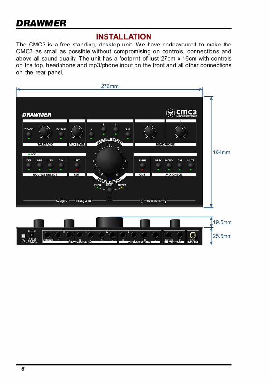
DRAWMERINSTALLATION
The CMC3 is a free standing, desktop unit. We have endeavoured to make theCMC3 as small as possible without compromising on controls, connections andabove all sound quality. The unit has a footprint of just 27cm x 16cm with controlson the top, headphone and mp3/phone input on the front and all other connectionson the rear panel.
6
CMC3 - Monitor Controller
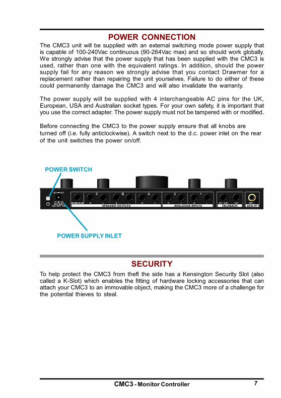
POWER CONNECTION
7
The CMC3 unit will be supplied with an external switching mode power supply thatis capable of 100-240Vac continuous (90-264Vac max) and so should work globally.We strongly advise that the power supply that has been supplied with the CMC3 isused, rather than one with the equivalent ratings. In addition, should the powersupply fail for any reason we strongly advise that you contact Drawmer for areplacement rather than repairing the unit yourselves. Failure to do either of thesecould permanently damage the CMC3 and will also invalidate the warranty.
The power supply will be supplied with 4 interchangeable AC pins for the UK,European, USA and Australian socket types. For your own safety, it is important thatyou use the correct adapter. The power supply must not be tampered with or modified.
Before connecting the CMC3 to the power supply ensure that all knobs areturned off (i.e. fully anticlockwise). A switch next to the d.c. power inlet on the rearof the unit switches the power on/off.
To help protect the CMC3 from theft the side has a Kensington Security Slot (alsocalled a K-Slot) which enables the fitting of hardware locking accessories that canattach your CMC3 to an immovable object, making the CMC3 more of a challenge forthe potential thieves to steal.
SECURITY
POWER SWITCH
POWER SUPPLY INLET

DRAWMERAUDIO CONNECTIONS
• Ground Loops:If ground loop problems areencountered, never disconnect themains earth, but instead, trydisconnecting the signal screen onone end of each of the cablesconnecting the outputs of the CMC3to the patchbay. If such measuresare necessary, balanced operationis recommended.
8
• Interference:If the unit is to be used where itmaybe exposed to high levels ofdisturbance such as found close toa TV or radio transmitter, we advisethat the unit is operated in abalanced configuration. Thescreens of the signal cables shouldbe connected to the chassisconnection on the XLR connector asopposed to connecting to pin1. TheCMC3 conforms to the EMCstandards.
Cable Wiring for TalkBack Output (Mono) to Stereo Distribution

CMC3 - Monitor Controller
TYPICAL CONNECTION GUIDE
9

DRAWMERCONTROL DESCRIPTION
As well as a transparent and precise signal path the CMC3 Compact MonitorController incorporates many impressive features which are invaluable to the soundengineer when listening to and examining the quality of the audio.
CHAPTER 2
1 SOURCE SELECTFour switches select which of the analogue inputs - I/P1, I/P2 (9) and AUX (1b), anddigital input - DIGI (8), are heard at the Speaker Outputs (10) and Headphones (6b).Each can be operated individually or simultaneously and in any combination. Whenoperated simultaneously the individual signals are summed into a single stereosignal. Note that the CMC3 does not provide individual level trims for the I/P1, I/P2and DIGI inputs and so any level matching should be applied before it reaches theCMC3.The digital DAC converts up to 192kHz/24 Bit and is via SPDIF (8) phono socketlocated on the rear. A LOCK led above the switch shows when the signal is strongand the CMC3 is locked in, if not lit the digital signal should be checked.An AUX 3.5mm stereo jack input is located on the front panel (1b) to allow easyaccess to connect a MP3 player, smartphone or similar audio device. A controlknob (1c) allows the adjustment of the AUX volume to match the system level.
10
CMC3 - Monitor Controller
2 MASTER VOLUMEThe Monitor Volume control (2) adjusts the signal level of both stereo channels forall speaker outputs. The Volume knob affects the volume of the monitors A,B,C andSUB only and does not have a bearing on any other output such as the headphonesor talkback jack.
A secondary preset volume control on the front edge (2a) provides a repeatablecalibrated output level for the monitors, so that at the press of the switch just belowthe main volume knob the engineer can hear the mix at the same predeterminedvolume, time after time, without having to meticulously adjust controls. Once thesystem is calibrated the predetermined level could be set via a screwdriver to themaximum listening level, 85dB in the case of TV, film and music, for example, or toa standard listening level for radio, or even a preferred level for quiet passage. Thelevel chosen is at the discretion of the operator.
Both the volume knob and preset control circuit designs incorporate identicalparallelled custom quad potentiometers, for excellent channel matching and asmooth feel, with a range from Off (-infinity) to +6dB of gain.
Because the circuitry is active it allows for the signal level to be increased, ratherthan only attenuated, making subtle problems within the mix (such as noise at lowlevels, or unwanted harmonics, for example) more obvious and easier to iron out,especially during musical passages that would normally be quiet.
Before you can make full effective use of the Volume control it is necessary tocalibrate the entire monitoring system, this allows for accurate level control, aswell as left/right balance throughout the knob’s range. Note that the actual outputlevels, including the maximum output level and the position of unity gain (0dB)around the knob, will alter depending on the calibration of the monitors.
WARNING:It is recommended that you turn the volume control down to a lower level beforeturning the CMC3 off - this is to ensure that a sudden volume increase whenturning on does not damage your speakers or your hearing.In addition, do not use excessive force at either end of the volume knob - it’ssize would mean that damaging the potentiometer is possible.
Note that on the underside of the CMC3 there are 2 rotary controls that allow the leftand right speaker level of all of the Speaker Outputs (10) to be trimmed. If the inputlevels into the CMC3 are very high the operator will find that the optimum location ofthe volume knob (i.e. 85dB output level) would be at around 9 o’clock or worse -leaving them with only a few degrees of rotation in which to lower the volume. Byadjusting the trims underneath this can be improved to give the preferred listeninglevel to somewhere more useful, such as the 12 o’clock position. This is especiallyuseful for those studios who work at high gain levels, allowing them to come intothe CMC3 ‘hot’.
To alter the speaker level trims use a small screwdriver to turn - counter-clockwiseturns the speaker level down, and clockwise up.
11

DRAWMERSPEAKER SELECT
Four switches select which of the four speaker outputs A, B, C or SUB are heard(10).Each switch can be operated individually or simultaneously and in any combinationand is perfect for performing A/B comparisons between various monitor setups. Asthe switches do not toggle between outputs when doing A/B comparisons both ofthose switches should be pressed at the same time i.e. to compare speakers Aand C, with A active press both the A and C switches to swap the output to C active,and then again to return to the previous setting - this method can be used betweenall four outputs if required.
An additional benefit is derived when using a sub-bass. If the sub-bass is attachedto the SUB/MONO output on the rear of the MC3.1, outputs A and B could deliver thehigher frequencies and allow for A/B (or in this case A+Sub/B+Sub) comparisonsbetween the two monitor setups by pressing the A and B switches simultaneouslyand leaving SUB always active. In addition, a full frequency range monitor could beattached to C, so, with the C switch active SUB should be disengaged.
MIX CHECKINGThe Mix Checking section allows the engineer to test various aspects of the mixwithout having to alter the signal earlier in the chain and potentially effect therecording, and is a very thorough and versatile checking tool. The switches areespecially useful when used in conjunction with each other.
Phase Reverse: Inverts the polarity of the signal on the Left Channel and is usedprimarily to outline any phase problems that may be occurring in the mix/recordingsuch as phase cancellation, or an unbalanced stereo signal. As the switch istoggled any phase issues will become more apparent and easier to identify.
Mono: With the switch active both Left and Right stereo signals are combined intoa single mono signal.It is necessary when testing the audio to not only listen to the signal in stereo butalso in mono. It helps to outline problems in the mix, but also when testing for useon non-standard applications such as for broadcast or mobile phone.
Dim: With the switch active the output level is attenuated by 20dB’s. It enables youto lower the volume without adjusting any of the settings.
Mute: Cuts the level of both channels and is especially useful in an emergency. IfLeft Cut and Right Cut are both active it is just the same as Mute being active.Note that Mute does not affect the headphones (6a, 6b) in the same way as it doesthe speakers (10). With the Mute switch active the headphones will still pass audioin just the same way as if it was off, they are not affected. This allows for someoneto edit audio using headphones whilst a conversation is occurring in the controlroom, for example.
CUTLeft Cut (5a): Mutes the Left channel signal allowing only the right signal to beheard,Right Cut (5b): Mutes the Right channel signal allowing only the left signal to beheard,
4
5
3
12
CMC3 - Monitor Controller
6
Note that the left and right Cut do have an influence on both the speaker outputsand the headphones.When activating Left or Right Cut whilst using headphones the signal is not 100%panned one way or the other - i.e. the signal centre moves to the side but is notcompletely removed from the opposite ear of the headphone - this is so that theLeft/Right Cut sounds a little more natural, after all, if listening through speakerswith only the left speaker active some of the signal well reach the right ear a fewmilliseconds later.
HEADPHONEThe CMC3 has two dedicated headphone amplifiers with outputs, via 1/4” TRSjacks, on the front face (6b) and level control (6a) on the front face - Note that thelevel control is not affected by the main large monitor volume knob (2), and have nobearing on volume of the rear panel outputs (10).
Warning:It is advisable to unplug the headphones before switching the CMC3 on or off.It is also recommended that you turn the headphone level down before insertingthe jack, and turn it up to your desired listening level - these measures will notonly prevent your ears from being damaged but also the headphone’s drivers.Also, note that these are high quality circuits and have been designed forprofessional headphones, so care must be taken when using lower standard,consumer quality headphones as damage could occur.
TALKBACKThe MC3.1 has a dedicated talkback function including inbuilt microphone, externalmicrophone port and gain level control.
External Mic Switch: When active disengages the inbuilt front panel microphoneand routes the operator’s voice through an external microphone (not supplied),which is plugged into the rear panel (11).
Talkback Active Switch: When active engages either the inbuilt or externalmicrophone and routes the operator’s voice through the headphones and also tothe talkback output on the rear of the unit (11). The switch is non-latching and somust be held in to be active.
Talkback Level. The knob adjusts the gain level of the talkback microphone. It canbe adjusted to compensate for the distance that the operator is from the microphone,how loud his voice is, or the volume of the underlying music played, as well asseveral other factors.
TalkBack Microphone. An electret condenser microphone as been incorporatedinto the CMC3 and is located below the Volume controls in the bottom centre of thefront panel.
Activating the Talkback automatically engages the Dim switch (i.e. attenuates thevolume by 20dB) for the headphones (6) and also the speaker outputs (10) makingit possible for the artist to clearly hear the instruction.
As well as the headphones the talkback signal is also routed to the direct talkbackoutput jack on the rear of the unit (11) to be routed at the engineers discretion.
7
13
DRAWMER
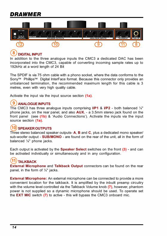
DIGITAL INPUTIn addition to the three analogue inputs the CMC3 a dedicated DAC has beenincorporated into the CMC3, capable of converting incoming sample rates up to192kHz at a word length of 24 Bit
The SPDIF is via 75 ohm cable with a phono socket, where the data conforms to theSony Phillips Digital InterFace format. Because this connector only provides anunbalanced termination, the recommended maximum length for this cable is 3metres, even with very high quality cable.
Activate the input via the input source section (1a).
ANALOGUE INPUTSThe CMC3 has three analogue inputs comprising I/P1 & I/P2 - both balanced ¼"phone jacks, on the rear panel, and also AUX. - a 3.5mm stereo jack found on thefront panel (see (1b) & ‘Audio Connections’). Activate the inputs via the inputsource section (1a).
SPEAKER OUTPUTSThree stereo balanced speaker outputs- A, B and C, plus a dedicated mono speaker/sub-woofer output - SUB/MONO - are found on the rear of the unit, all in the form ofbalanced ¼" phone jacks.
Each output is activated by the Speaker Select switches on the front (3) - and canbe activated individually or simultaneously and in any configuration.
TALKBACKExternal Microphone and Talkback Output connectors can be found on the rearpanel, in the form of ¼" jacks.
External Microphone: An external microphone can be connected to provide a moreconvenient location for the talkback. It is amplified by the inbuilt preamp circuitrywith the volume level controlled via the Talkback Volume knob (7), however, phantompower is not supplied so a dynamic microphone should be used. To operate setthe EXT MIC switch (7) to active - this will bypass the CMC3 onboard mic.
8
9
10
11
14

CMC3 - Monitor Controller
Talkback Output: A dedicated ¼" mono talkback output jack can be found on therear panel, so that, as well as being routed through the headphones, a talkbacksignal can be routed to other devices at the engineers discretion. This could usuallybe patched into the live-room active monitor speakers for convenience whenrecording acoustic ensembles where the performers may not wish or need to wearheadphones. It could also be used as an added channel on a mixing desk to bepatched into a multiple headphone amplifier along with the stereo mix, for example.The jack also allows for routing into a separate channel of a DAW, or other recordingfacility, to allow for information overdubs to be added to a recording.
To connect the mono talkback to a Dual Mono jack use the following cable wiring:
POWERThe CMC3 will be supplied with an external switching mode power supply that iscapable of 100-240Vac continuous (90-264Vac max) and should work globally, butis supplied with a cable suitable for domestic power outlets in your country. Westrongly advise that the power supply that has been supplied with the CMC3 isused, rather than one with the equivalent ratings. The push button switch activatesthe CMC3. Note that a timed relay protection circuit has been incorporated intocircuit to prevent bangs and other potentially harmful artifacts from occurring duringpower up and power down.
12
15

DRAWMER
16
Mix Checking TipsDue to the versatility of the CMC3 some very useful techniques for checking yourmix can easily be achieved, that can help improve the balance within a mix, pinpointstereo width, phase and mono problems, and also aid when monogising.
The following are a few handy tips to help eradicate problems and bring about abalance within the mix:
Not too loud...Give your ears a break. Do not have the volume too loud - frequent monitoring atanything above 90dB will only make your ears tired, meaning that you won’t reallyhear the problems that may be occurring, and give you a false sense that the mixsounds nice and loud. Also, constant listening at anything above 100dB will probablyhave a long term detrimental effect on your hearing.
Shhhh...Get into a habit of listening to your mix at very low levels quite often. Remember thatnot everyone listening to your song has music blasting out. As well as giving yourears a break, it will heighten problems in the mix - Do the key elements have agood balance, or are some instruments more prominent than they should be? Ifsomething is too quiet or loud adjust its volume or use E.Q. to fix it. If the mixsounds good at low levels it’s likely that it will when loud.
Note that on the CMC3 it is better to lower the volume level using the DIM switchand then turn the volume up, rather than only turning the volume down, as youmaintain greater control over the volume as well as better left/right channelmatching.
Increase the Volume of Quiet Passages.Because the CMC3 circuitry is active it allows for the signal level to be increased,rather than only attenuated, making subtle problems within the mix, such as noiseat low levels, or unwanted harmonics, more obvious and easier to iron out, especiallyduring passages that would normally be quiet.
Here, There and Everywhere......Listen to your mix on as many systems as possible. The two monitor outputsallows for the addition of a non standard testing setup i.e. the system could beforced to emulate low-quality domestic reproduction systems as well as car speakersor a portable radio, by incorporating limited-bandwidth speakers to output B. In suchconditions you may find that an instrument drops out of the mix, or another is tooprominent, and adjustment to the mix need to be made. For best results calibratethe speakers to match the output level of the rest of the system.
Phase Reverse...Make use of the phase reverse switch. If the sound doesn't become less focusedwhen the polarity is flipped then there is something wrong somewhere. Not onlywill the switch help confirm that the monitors are wired up in the correct polarity,phase inversion on a particular instrument can at times improve the way theinstrument interacts with the rest of the mix by removing the phase cancellation.

CMC3 - Monitor Controller 17
Cut It Out...Using the left and right cut switches will highlight the stereo balance of eachchannel. In stereo the mix sounds ok, however, it may be that you want an instrumentto be panned so far left that it doesn’t occur at all in the right channel, by cutting theleft and only hearing the right channel you will hear whether the instrument bleedsacross, and panning adjustment can be made.
MonogisingCheck your mix in mono - often! Just because a mix sounds good in stereo doesn'tmean it will sound good when the left and right channels are combined. Why shouldyou care if your mix sounds good in mono? Well, most live music venues and danceclub sound systems are mono - running the PA or sound system in mono is commonpractice to ensure music sounds good everywhere in the room because it removesthe ‘sweet spot’ and the complex phase issues of stereo. In many cases the lowfrequencies will be put through a crossover and summed to mono before beingsent to the sub, such as in a home theatre system, for example. Monogising is alsonecessary when testing the audio for use on non-standard applications such asfor broadcast or mobile phone.
In addition, monogising will highlight phase problems. In some cases, when youactivate the Mono switch you may hear comb-filtering, which will colour the sound ofyour mix and cause peaks and dips in its frequency response. When a stereo mix iscombined into mono any elements that are out of phase will drop in level or mayeven disappear completely. This could be because left and right outputs are wiredout of phase but its more likely to be due to phase cancellation. What causesphase cancellation?
Many stereo widening effects and techniques, such as chorus;
Simultaneous direct box and mic recording - If you've ever recorded a guitarsimultaneously through a direct box and a microphone, you may have noticedthe time alignment problems this causes. This type of situation can often befixed by careful mic placement, or realigning the waveform in a DAW;
Where more that one microphone is used to record a source - on a multi-mikeddrumkit two mics may pick up the same signal and cancel each other out. Onehandy tip is to adjust the panning of your drums whilst in mono - the phasecancellation of the drums will improve, and sound even better when revertedback to stereo.
Listening in mono also highlights problems with the stereo width and balance ofthe mix and is more apparent when you use a lot of stereo-widening or width-enhancing techniques and tools. Switching mono in and out fairly quickly maymake it apparent that the centre of the mix is shifting to the left or right, somethingthat may go unnoticed if only working in stereo.
True MonoAs a mono signal would normally originate from a single source it would be wrongto simply activate the mono switch - as both left and right speakers are still active.When you listen to a mono signal on two speakers, you hear a false or 'phantom'image which is derived midway between the speakers, but because both speakersare contributing to the sound, the level of the bass seems to be over-inflated. Totruly hear a monogised signal via one speaker (the way everyone else will hear it)
DRAWMER
18
the mono switch should be active but also either Left Cut or Right Cut should alsobe activated (depending on preference/location) to derive the signal from a singlelocation.
Listen to the ‘Stereo difference’ or side signalA very useful facility of the CMC3 is the ability to listen to the ‘stereo difference’ orside signal, very quickly and easily. The side signal is the difference between thetwo channels, and describes those elements that contribute to the stereo width.
Hearing the stereo difference is so simple using the CMC3: with the stereo signalplaying, activate the Phase Reverse switch, and then sum the left and right channelsusing the Mono switch (in other words Left-Right). It’s that simple.
Being able to audition the ‘side’ signal is particularly useful for judging the qualityand quantity of any ambience or reverberation in a stereo mix. It is also an invaluablefacility if the stereo recording has timing differences between channels (such ascaused by an azimuth error on a tape machine), or for aligning a pair of deskchannels for use with X-Y stereo mic pairs. In both cases, listening for a deepcancellation null, as the two signals cancel each other out, is a very fast andaccurate way of matching levels in each channel, which is the basis of accuratealignment.
Active vs. Passive CircuitsThere is a great debate as to which is best - a passive or active monitor controlcircuit. The theory is that passive monitor controllers must be best, since they donot add transformers or other components to the signal path, along with thenoise and distortion that they can bring, however they have severe disadvantagesover active circuits. The most significant is that the output impedance of theconnected source equipment and the input impedance of the power amp oractive speaker will affect the workings of the passive controller - each needsbuffering to remain reliable and consistent, otherwise level matching problemswill be inevitable. Since even the best cables have capacitance, it is extremelyimportant to keep cable lengths to an absolute minimum (i.e. less than a coupleof meters) to avoid signal degradation especially in high frequency signals.Long cables will act like a simple low frequency filter.Furthermore, it is incredibly difficult to get a mono signal from a passive circuitwithout affecting the sound so any kind of reliable mix checking becomes nearimpossible.Active designs make it easier and more reliable to guarantee a high performancelevel as the signal attenuation and switching is actively buffered, as well asproviding complete control over distortions, crosstalk, frequency response, andtransient fidelity. Moreover, cable lengths of tens of meters should not be anissue. Furthermore, it makes it possible to introduce mix checking features thatwould otherwise be missing. The disadvantage with active monitor controllers isthat the electronics have the potential to introduce noise and distortion. Designinga clean monitor control system is far from simple, however, using only the verybest components and clever circuit design, with the Drawmer CMC3 we haveovercome all of these problems and managed to combine the best of both -whilst retaining the transparency and responsiveness that a passive circuit wouldbring with the advantages of an active one.
CMC3 - Monitor Controller
CHAPTER 3
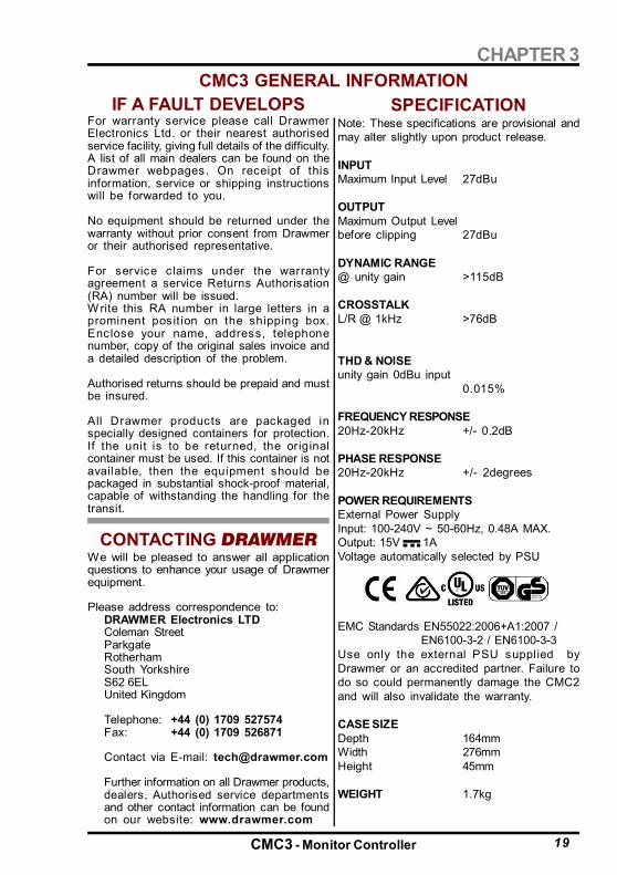
SPECIFICATIONNote: These specifications are provisional andmay alter slightly upon product release.
INPUTMaximum Input Level 27dBu
OUTPUTMaximum Output Levelbefore clipping 27dBu
DYNAMIC RANGE@ unity gain >115dB
CROSSTALKL/R @ 1kHz >76dB
THD & NOISEunity gain 0dBu input
0.015%
FREQUENCY RESPONSE20Hz-20kHz +/- 0.2dB
PHASE RESPONSE20Hz-20kHz +/- 2degrees
POWER REQUIREMENTSExternal Power SupplyInput: 100-240V ~ 50-60Hz, 0.48A MAX.Output: 15V 1AVoltage automatically selected by PSU
EMC Standards EN55022:2006+A1:2007 /EN6100-3-2 / EN6100-3-3
Use only the external PSU supplied byDrawmer or an accredited partner. Failure todo so could permanently damage the CMC2and will also invalidate the warranty.
CASE SIZEDepth 164mmWidth 276mmHeight 45mm
WEIGHT 1.7kg
For warranty service please call DrawmerElectronics Ltd. or their nearest authorisedservice facility, giving full details of the difficulty.A list of all main dealers can be found on theDrawmer webpages. On receipt of thisinformation, service or shipping instructionswill be forwarded to you.
No equipment should be returned under thewarranty without prior consent from Drawmeror their authorised representative.
For service c laims under the warrantyagreement a service Returns Authorisation(RA) number will be issued.W rite this RA number in large letters in aprominent posit ion on the shipping box.Enclose your name, address, telephonenumber, copy of the original sales invoice anda detailed description of the problem.
Authorised returns should be prepaid and mustbe insured.
All Drawmer products are packaged inspecially designed containers for protection.If the unit is to be returned, the originalcontainer must be used. If this container is notavailable, then the equipment should bepackaged in substantial shock-proof material,capable of withstanding the handling for thetransit.
CONTACTING DRAWMERWe will be pleased to answer all applicationquestions to enhance your usage of Drawmerequipment.
Please address correspondence to:DRAWMER Electronics LTDColeman StreetParkgateRotherhamSouth YorkshireS62 6ELUnited Kingdom
Telephone: +44 (0) 1709 527574Fax: +44 (0) 1709 526871
Contact via E-mail: [email protected]
Further information on all Drawmer products,dealers, Authorised service departmentsand other contact information can be foundon our website: www.drawmer.com
CMC3 GENERAL INFORMATIONIF A FAULT DEVELOPS
19

DRAWMER
Ref:1v0B 14-08-18
BLOCK DIAGRAM
20