cm/avs user's guide - massachusetts institute of...
TRANSCRIPT

TheConnection MachineSystem
CM/AVS User's Guide
Version 1.0February 1993
Thinking Machines CorporationCambridge, Massachusetts

First printing, February 1993
The information in this document is subject to change without notice and should not be construed as acommitment by Thinking Machines Corporation. Thinking Machines reserves the right to make changes to anyproduct described herein.
Although the information in this document has been reviewed and is believed to be reliable, Thinking MachinesCorporation assumes no liability for errrs in this document. Thinking Machines does not assume any liabilityarising from the application or use of any information or product described herein.
Connection Machine® is a registered trademark of Thinking Machines Corporation.
CM, CM-2, CM-200, CM-5, CM-5 Scale 3, and DataVault are trademarks of Thinking Machines Corporation.
CMosr, CMAX, and Prism are trademarks of Thinking Machines Corporation.C*® is a registered trademark of Thinking Machines Corporation.Paris, *Lisp, and CM Fortran are trademarks of Thinking Machines Corporation.
CMMD, CMSSL, and CMX11 are trademarks of Thinking Machines Corporation.Scalable Computing (SC) is a trademark of Thinking Machines Corporation.Thinking Machines® is a registered trademark of Thinking Machines Coporation.
AVS is a trademark of Advanced Visual Systems, Inc.
SPARC and SPARCstation are trademarks of SPARC International, Inc.
Sun, Sun-4, and Sun Workstation are trademarks of Sun Microsystems, Inc.
UNIX is a registered trademark of UNIX System Laboratories, Inc.
The X Window System is a trademark of the Massachusetts Institute of Technology.
Copyright C 1993 by Thinking Machines Corporation. All rights reserved.
Thinking Machines Corporation245 First Street
Cambridge, Massachusetts 02142-1264(617) 234-1000
. . . . . . . . . . . . . .. 11 . . . . . . . . .. . .......... . . . . . . . . . . . . . . .

Contents
About This Manual .......................................................... vii
Customer Support ........................................................... xi
Chapter 1 Introduction .................................... .... 1
1.3 Overview of CVMAVS ......................................... 1
1.4 The CM/AVS Package ........................................... 2
Chapter 2 Using CM/AVS Modules .................................. 5
2.1 The CM/AVS Modules ........................................... 5
2.2 Using CM/AVS Modules in a Network ......... ................ 6
2.3 Preparing to Run Remote CM/AVS Modules ......................... 7
2.4 Running a Remote CM/AVS Module - Tutorial ...................... 8
2.5 An Important Note about Performance .............................. 12
2.6 Running CM/AVS Modules Locally ................................ 13
2.7 Cleaning Up ........................................ ..... 14
Chapter 3 Writing CM/AVS Modules .................................. 15
3.1 The Field Type ................................................ 15
3.2 The Parallel Field Type ......................................... 16
3.2.1 Declaring a Parallel Field ................................ 17
3.2.2 Passing a Parallel Field .................................. 17
3.3 Using AVS Field Routines on Parallel Fields ......................... 17
3.4 Allocating Parallel Fields ......................................... 18
3.4.1 Parallel Input Ports ..................................... 18
3.4.2 Explicit Allocation ..................................... 19
3.5 Accessing Field Data and Coordinates .............................. 203.5.1 Access Routines ....................................... 20
3.5.2 Primitive Data Types ................................... 22
3.5.3 Data Array Layout ..................................... 23
Version 1.0, February 1993Copyright © 1993 Thinking Machines Corporation iii

CM/AVSUer'sGuid
3.5.4 Coordinate Array Layout ................................ 23
3.5.5 Declaring the Am
3.6 Luminance Module Example3.6.1 Luminance Modu
3.7 The CM/AVS Header Files
3.8 The CM/AVS Libraries ...
3.9 Compiling a Module .....
3.10 Debugging a Module .....
3.11 Getting Help............
3.12 Multiple-Module Binaries.
Appendix A
A.1
A.2
ays .... ................................ 23
..........................leCode ...............................................
....... ,.................
..........................
............... e.........
...........................
...........................
CMIAVS Routines.
CMAVScorout-init ...
CMAVSdataalloc ....
A.3 CMAVSfieldalloc..
A.4
A.5
A.6
A.7
A.8
A.9
A.10
CMAVSfieldallocdatU
CMAVSfieId_aloc_poii
CMAVSfield_copy..poi
CMAVSfield_dataget
CMAVSfieldpoints_ge
CMAVSfield_reset min
CMAVSis_field_onCM
.......................
.......................
.......................
.......................
a_shape ................
itsshape ...............ts ....... ....... ......its
max ...................I .... ... .... . .....
Appendix B CM/AVS Modules (man pages) ...
antialias cm ........................
clamp cm ..........................
color range cm ......................
colorizer cm ........................
combine scalars cm ..................
compare field cm ....................
compute gradient cm ................
contrast cm ........................
downsize cm ........................
24
24
27
27
28
29
29
30
31
32
32
33
34
35
35
36
37
38
39
41
43
45
48
51
54
57
60
64
674
Version 1.0, February 1993Copyright © 1993 Thinking Machines Corporation
CICA VS User 's Gui-deiv
........................
............
............
............
............
............
............
......
......
......
......
......
......
......
......
......
......
......
............
............
............
............
............
............
............
............
............
............
............
..........................
..........................
..........................
..........................
..........................
..........................
..........................
..........................
..........................
..........................

Cotents _Vor,@$C- k | , ; R ,,,>Ss> '
extract scalar cm ...
fft cm ............
field math cm ....................
field to byte cm ..................
field to double cm ................
field to float cm ..................
field to int cm ...................
luminance cm ....................
orthogonal slicer cm ..............
threshold cm ....................
Appendix C
............................. 74
............................. 78
............................. 80
............................. 82
............................. 84
............................. 86
............................. 89
............................. 93
Unsupported Programs and Modules ..
avstoppm .........................ppmtoavs .........................field to polygons ...................
95
97
98
99
101field to spheres .......................
Index ...... .............................................................. 105
Version 1.0, February 1993Copyright © 1993 Thinking Machines Corporation
70
72
Contents v
..........................................
.........................
.........................
.........................
.........................
.........................
. .

4

About This Manual
Objectives of This Manual
This manual describes CM/AVS. Working in conjunction with the ApplicationVisualization System (AVS), CM/AVS provides a graphic programmingenvironment for building distributed visualization applications. This manual tellshow to build applications that include computation on a CM-5 system, and howto create your own CM/AVS modules.
Intended Audience
This manual is intended for
* Users who are familiar with the AVS product and who want to visualizedata on a CM-5 system. You must also be familiar with using a CM-5.
* Application developers who want to write modules that are compatiblewith CM/AVS. You should be an experienced C or Fortran programmer,knowledgeable about AVS, and familiar with C* or CM Fortran and usinga CM-5.
Revision Information
This is a new manual.
Organization of This Manual
This manual contains the following chapters:
Chapter 1 IntroductionAn overview of CM/AVS concepts and a list of installed compo-nents.
Version 1.0, February 1993Copyright 1993 Thinking Machines Corporation vii
VUi1 nIVAra1 VuSr a rJULu I
Chapter 2 Using CM/AVS ModulesHow to set up the environment to run CM/AVS modules locallyon a CM-5 partition manager or remotely from a workstation.How to to build a simple application "network" to use a CM/AVSmodule remotely.
Chapter 3 Writing CM/AVS ModulesA brief discussion of the properties that differentiate serial andparallel fields. How to allocate and access parallel fields. Exam-ple module. How to compile, debug, and link modules.
Appendix A CM/AVS RoutinesDescriptions of the CM/AVS routines.
Appendix B CM/AVS ModulesDescriptions of the CM/AVS modules.
Appendix C Unsupported Programs and ModulesDescriptions of programs and modules that are included in theCM/AVS package without guarantee or support.
Related Documents
The following document contains information concerning the hardware andsoftware requirements and installation of CM/AVS:
* CM/AVS Release Notes for Version 1.0.
You should have the complete AVS document set. The following manuals arerequired:
* AVS User GuideAn introduction to AVS. To use CM/AVS effectively, you must be familiarwith the concepts introduced in this manual.
* AVS Developer S GuideHow to write AVS modules.
* AVS Module ReferenceDetailed descriptions of all the AVS modules. 4
Version 1.0, February 1993Copyright Q 1993 Thinking Machines Corporation
fl ISIA TIC 7 7 --- J-'..:

About This M
* AVS Tutorial GuideA tutorial introduction to using AVS.
AVS Applications GuideInformation on using the Module Generator.
Notation Conventions
The table below displays the notation conventions observed in this manual.
Convention Meaning
bold typewriter
% bold typewriterregular typewriter
typewriter
italics
UNIX and CM System Software commands, com-mand options, and filenames, when they appearembedded in text. Also, programming languageelements, such as keywords, operators, and func-tion names, when they appear embedded in text.
In interactive examples, user input is shown inbold typewriter and system output is shown inregular typewriter font.
Code examples and code fragments.
Argument names and placeholders in function andcommand formats. -
Version 1.0, February 1993Copyright © 1993 Thinking Machines Corporation
About This Manual ix


Customer Support
Thinking Machines Customer Support encourages customers to report errors in
Connection Machine operation and to suggest improvements in our products.
When reporting an error, please provide as much information as possible to help
Ius identify and correct the problem. A code example that failed to execute, a
session transcript, the record of a backtrace, or other such information cangreatly reduce the time it takes Thinking Machines to respond to the report.
If your site has an applications engineer or a local site coordinator, please contact
that person directly for support. Otherwise, please contact Thinking Machines'home office customer support staff:
InternetElectronic Mail:
uucpElectronic Mail:
U.S. Mail:
Telephone:
Version 1.0, February 1993
Copyright © 1993 Thinking Machines Corporation
ames!think!customer-support
Thinking Machines CorporationCustomer Support245 First Street
Cambridge, Massachusetts 02142-1264
(617) 234-4000
xi


Chapter 1
Introduction
CM/AVS adapts and extends the Application Visualization System (AVS) to therealm of the CM-5. AVS provides a graphic programming environment in whicha user builds a distributed visualization application. An application may involvediverse operations such as filtering, graphing, volume rendering, polygonrendering, image processing, and animation. CM/AVS enables an application tooperate on data that is distributed on CM-5 processing nodes and to interoperatewith data from other sources. CM/AVS also facilitates the incorporation of CM-5code into a CM/AVS application.
CM/AVS is not run separately from AVS. A user runs AVS normally, usingCM/AVS modules and functions to handle data on the CM-5.
1.1 Overview of CM/AVS
The building blocks of an AVS application program are small, packaged units ofcode, called modules. Most modules process typed data input(s) into typed dataoutput(s). Each module performs a given function. The function may be assimple as adding two arrays, or as complicated as extracting isosurfaces of avolume. When a CM/AVS module is used, the function is performed on a CM-5.
Modules are connected to form larger applications, called networks. In anetwork, information is passed between the modules as various data types. Onlythe field data type, which represents an array of data, is relevant to CM/AVS.CM/AVS supports a parallel field that accommodates the distribution of dataacross the CM-5 processing nodes. CM/AVS includes routines to allocate theparallel arrays, and to access the data and coordinates as CM Fortran arrays orC* parallel variables.
Version 1.0, February 1993Copyright © 1993 Thinking Machines Corporation 1

2 C/ -S U- Gud
When CM/AVS modules that operate on parallel data are connected with AVSmodules that operate on serial data, CMIAVS routines convert the data betweenparallel and serial fields as required. The conversion is transparent to the user andto the module writer.
The AVS Network Editor visual interface makes it easy to build applicationnetworks graphically. Alternatively, the Network Editor may be driven by theAVS Command Language Interpreter.
1.2 The CM/AVS Package
The CM/AVS software package includes:
* A set of modules that handle data on a CM-5. The modules are describedin Appendix B.
* A set of routines that provide general operations for parallel fields. Theroutines are used by the CM/AVS modules and users may incorporate themin their own C* or CM Fortran modules. The concepts that differentiateserial and parallel fields are discussed in Chapter 3. The routines aredescribed in Appendix A.
· On-line code examples, help files, and release notes.
CM/AVS is installed on the CM-5 compile server as follows:
CM/AVS libraries /usr/lib
CM/AVS include files
Combined module binary,list-dir file, andlibrary description file
Examples
Module help files
/usr/include
/usr/lib/cmavs_library
/usr/examples/cmavs
/usr/doc/cmavs/modules
Version 1.0, February 1993Copyright 1993 Thinking Machines Corporation
2 CICA VS User $ Guide

.v* a 4. - 8) _
Release notes /usr/doc/cmavs-l.0.releasenotes
Source (by license only) /usr/src/cmavs
The directory /usr/examples/cmavs/unsupported contains items that aresupplied without guarantee or support. The README file in this directorycontains information about its contents. Appendix C contains additionalinformation about unsupported programs and modules.
Version 1.0, February 1993Convriht © 1993 ThinkinR Machines Corporation
Chapter . Introtuction 3


Chapter 2
Using CM/AVS Modules
This chapter tells how to execute the CM/AVS modules from a workstation andfrom a CM-5 partition manager. The following topics are discussed:
* The CM/AVS Modules
· Using CM/AVS Modules in a Network
· Preparing to Run Remote CM/AVS Modules
· Running a Remote CM/AVS Module - Tutorial
· An Important Note about Performance
· Running CM/AVS Modules Locally
· Cleaning Up
For a more thorough discussion of remote module execution, please refer to theAVS Users Guide.
2.1 The CM/AVS Modules
CM/AVS provides the following modules. Most are CM-5 versions of AVSmodules. A detailed description of each module appears in Appendix B.
antialias cmclamp cm
color range cmcolozizer cmcombine scalars cm
Version 1.0, February 1993aL r____ wnf1^ ' nn .,, 3L,.'_A; nrr pnnrnfinn 5

~6~e~BB~s~ -
compare field cm
compute gradient cm
contrast cm
downsize cm
extract scalar cm
fft cm
field math cm
field to byte cm
field to double cm
field to float cm
field to int cm
luminance cm
orthogonal slicer cm
threshold cm
The following modules are unsupported. Detailed descriptions of these modulesappear in Appendix C.
field to polygons
field to spheres
2.2 Using CM/AVS Modules in a Network
AVS supports distributed computation over a heterogeneous network ofcomputers. While you run the AVS kernel on a local graphics workstation, youcan execute modules locally or on other workstations or systems. Using CM/AVS,you can also execute CM/AVS modules on a CM-5.
You use CMIAVS modules in exactly the same manner as AVS modules. Whenyou build a network, you may interconnect AVS modules and CM/AVS modules.
If you run AVS on a CM-5 partition manager, you can run CM/AVS moduleslocally. (We do not recommend this as a good use of partition managerresources.)
Version 1.0, February 1993Copyright ) 1993 Thinking Machines Corporation
6 CWA AVS User 5 Guide

~8i~$B~es~g p~sseasp~ ----
2.3 Preparing to Run Remote CM/AVS Modules
It is likely that you will run AVS on a local workstation and run the CM/AVSmodules on the CM-5. The remote use of any modules, including CM/AVS,requires some preparation.
AVS uses a "hosts file" to find remote modules. The file identifies remote hostsand the directories on those hosts that contain modules. The hosts file format isdescribed under Remote Module Execution in the Advanced Network Editorchapter in the AVS User s Guide.
You may choose to rely on the system administrator to maintain the file/usr/avs/runtime/hosts. Alternatively, you may choose to create andmaintain a private hosts file. In either case, your . avsrc initialization file mustpoint to a legitimate hosts file.
To create and use a . avsrc file, follow these steps:
1. Create a. avser file. AVS looks for this file first in the current directory,and then in your home directory. We recommend putting it in your homedirectory.
A minimal .averc file might look like this:
# Point to a file containing remote hosts
Hosts /home/yourname/.avs-hosts
where the specified hosts file is /home/yourname/. avs -hosts.
2. Check the hosts file:
· It must reside at the pathname specified in the .avsrc file. Thepathname must be valid on the system where AVS is invoked.
* It must contain one line of information for every remotehost/directory combination where you want AVS to look formodules.
Each information line in a hosts file contains four fields, in this order:
(1) A logical name that identifies a particular combination of a remotehost and a module directory. This logical name will appear in theRemote Host Browser. (Just the host name may be used for thispurpose, unless more than one module directory on the host is ofinterest. In that case, each of the directories requires its own line inthe hosts file.)
Version 1.0, February 1993CnnvriPht 1993 Thinking Machines CorDoration
Chapter Z. Using CWA AVS Modules 7

8 CM/ VUer'Gid
(2) Both the name of the remote shell program (the path to rsh) andthe actual host name of the remote machine. (For CW/AVS modules,the host name should be a CM-5 partition manager.) You may addoptions to rsh. The entire field is enclosed in double quotes.
(3) The directory on the remote host that should be searched formodules.
(4) The default data directory on the remote host.
To make the remote CM/AVS modules available, the hosts file mustcontain a line that specifies a CM/AVS modules directory on a partitionmanager. The line might look like this:
pep.think.com "/usr/ucb/rsh pep.think.com -n"
/usr/lib/cmavs library
/usr/avs/data
pep. think. con is the logical name of the CM-5 partition manager(pep. think. cor) and the module directory /usr/lib/cmavs_library. (Field 1)
/usr/ucb/rsh is the command to run a command shell on the remotemachine, whose real name is pep. think. com; -n is an rsh option thatprevents input conflicts with the caller. (Field 2)
/usr/lib/cmavs_library is the directory that contains CM/AVSmodules. (Field 3)
/usr/avs/data is the data directory. (Field 4)
2.4 Running a Remote CM/AVS Module - Tutorial
In this section, we build a simple network to turn an RGB image into a greyscaleimage. We use a CM/AVS module, luminance cm, in the network. The moduleis the CM-5 version of the AVS luminance module.
First, make the preparations described in Section 2.3. Then, follow these steps:
1. Start AVS and bring up the AVS network editor. From the menu in theupper left of the network editor menu, select Module Tools, as shownin Figure 1.
Version 1.0, February 1993Copyright © 1993 Thinking Machines Corporation
8 CWA AVS User k Guide

5 5.. .5 5B'9is2N 5:55 5:5::':i-" .5.:.$:: :.,,.,,. j,.f;- ,.,.5:.:.:.5 ..55.5::.... 5 .. 5:...:..... :. 5 ..5.........:55::55::5:5:::: : 55 5:5 ::::::s:::::55 : :5:: 5: : ::55::5 : S:::: :: : ::~~:: 55~s: 5 ~ 555~::55:::::5::55.5 5 :555:5: 5:5.:5~ : 5:55::555555s,.:
555 5 55:~555 55 5 55 555 55: S .. * . ... * .::..::55:::5, .: .. 5:: :.:::.:5:.55. :...55555...... ~ 555
2. Optional: If you want the CM/AVS module icons to appear under aCM Modules Library header instead of being incorporated in the AVSmodule lists, do the following:
Select Edit Module Library, then select Create Empty Library on the
resulting pop-up window. Enter cM Modules in the pop-up prompt fora name, then select OK. Close the Edit Module Library pop-upwindow. CM Modules appears as the selected AVS Module Libraryheader in the AVS Module Palette.
Figure 1. Module Tools menu.
3. Select Read Remote Module(s) from the Module Tools menu. This
brings up a Remote Host Browser containing a list of available hosts.Select a CM-5 partition manager (one that is named in .avs-hosts)from this list. In this example, we use pep, as shown in Figure 2.
The selection causes the display of the contents of the current directoryon the host. If the binary file cmarvs-modules is not in the contents list,change to the directory that contains it (/usr/lib/cmavs_library). Select cmavs-modules from. the list and close the moduleselection window.
Version 1.0, February 1993
Copyright (O 1993 Thinking Machines Corporation
Chapter 2. Using CWAVAFS Modules 9

!: AS :. -, !if!i * > ': .,·'> .!S *' / ' ..,' " : .>.1 :'0: .CM../A V :': ' ue::
Figure 2. Remote Host Browser.
When the read of the binary file is complete, an icon representing each
of its modules appears under the appropriate Library header. Each iconhas a button on the right side. On a remote module, this button is coloredpink.
4. Drag one instance each of the following modules into the network editorworkspace. Place them as shown in Figure 3. The appearance of colored
badges designating input and output ports indicates that the AVSmodules are active and ready to accept connections. Wait for the ports
to appear on one module before you drag in the next one. (Section 2.5explains the benefit of waiting.)
read image (Data Input list)
luminance cm (Filter list)
colorizer cm (Filter list)
display image (Data Output list)
When display image becomes active, the image display windowcomes up. Reposition it, if you like. (It will expand to about four times
its initial size to accomodate the result.)
5. When all four modules are active, connect the output of read image to
the input of luminance cm: position the cursor over the read image
output port, press the middle mouse button, move the cursor to theluminance cm input port, and release. Similarly, connect the output of
luminance cm to the input to colorizer cm, and the output of
colorizer cm to the input to display image. See Figure 3.
Version 1.0, February 1993Copyright © 1993 Thinking Machines Corporation
CMIA VS User Ss Guide10

Chapter 2. UsingSC WA VS Module 11e
6. Select read image on the Network Control Panel and read the image/usr/avs/data/image/mandrill.x. TOhis image file is includedwith AVS.) The modules in the network change color when they areactive, so you can watch as the image data progresses through thenetwork. During processing, it is actually transferred to the CM-5 forluminance and colorizer calculations, then back to the local workstationto be displayed. See Figure 3 and Figure 4.
Figure 3. The complete network and display.
Version 1.0, February 1993Copyright ) 1993 Thinking iachines Corporation
Chapter 2. Using CWA VS Modules 11
12 CM/A VS User ~ Guidei;ii:,:iiiii i : ::iii:: · ;i::ii !!!!!:i iii i!:i;:;: iii; : :i:i!!:!i l :::::.i !!iii:!!: !::E:ii .!i:5!!;:!~ i::!:!i:! Z.:i::i!ii:iiiiii i:1ii:iii!i!;~iiii1~:!ii iiii 'ii:!1i!!~i: i:!: ii!i ::::;..::.:....:..:.....i:.i:iii!1i
W
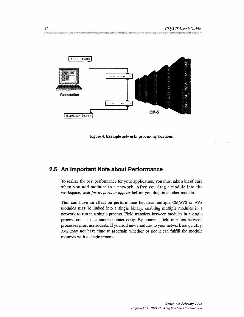
Figure 4. Example network: processing locations.
2.5 An Important Note about Performance
To realize the best performance for your application, you must take a bit of carewhen you add modules to a network. After you drag a module into theworkspace, wait for its ports to appear before you drag in another module.
This can have an effect on performance because multiple CM/AVS or AVSmodules may be linked into a single binary, enabling multiple modules in anetwork to run in a single process. Field transfers between modules in a singleprocess consist of a simple pointer copy. By contrast, field transfers betweenprocesses must use sockets. If you add new modules to your network too quickly,AVS may not have time to ascertain whether or not it can fulfill the modulerequests with a single process.
Version 1.0, February 1993Copyright Cc) 1993 Thinking Machines Corporation

Chapter 2. Using CM/A VS Modules 13
2.6 Running CM/AVS Modules Locally
Running AVS on a CM-5 partition manager does not make the best use of thepartition manager resources. However, it can be done, provided you follow thesesteps to make the CM/AVS modules accessible to the AVS Network Editor:
1. Start AVS and bring up the AVS Network Editor. From the menu in theupper left of the Network Editor menu, select Module Tools, as shownin Figure 5.
2. Optional: If you want the CM/AVS module icons to appear under aCM Modules Library header instead of being incorporated in the AVSmodule lists, do the following:
Select Edit Module Library, then select Create Empty Library on the
resulting pop-up window. Enter CM Modules in the pop-up prompt fora name, then select OK. Close the Edit Module Library pop-upwindow. CM Modules appears as the selected AVS Module Libraryheader in the AVS Module Palette.
Figure 5. Module Tools menu
3. Select Read Module(s) from the Network Editor list. A display showsthe contents of the current directory. If the binary file cmavs-modules
Version 1.0, February 1993Colyright C) 1993 Thinking Machines Corporation

14 CM/A VS User's-Guide
is not in the contents list,. change to the directory that contains it(/usr/lib/cmavslibrary). Select cmavs-modules from the list,then close the module selection window. (From this point, you may pickup with Step 4 in the tutorial, Section 2.4, if you like.)
2.7 Cleaning Up
If AVS terminates abnormally (if the kernel crashes or if there are networkproblems, for example), CM/AVS modules may be left running on the CM-5.Therefore, it is a good idea to use camps and check the partition manager processstatus after AVS terminates. Be sure that no stray modules continue to run andwaste system resources.
Version 1.0, February 1993Copyright 0 1993 Thinking Machines Corporation
14 CWA VS User ~ Guide

Chapter 3
Writing CM/AVS Modules
You can develop new code or adapt existing code to be compatible with theCM/AVS environment. You may combine your modules in a network withmodules from other sources.
This chapter talks about the aspects of code that are unique to handling parallel
arrays, including the topics listed below:
· The Parallel Field Type
· Using AVS Field Routines on Parallel Fields
· Allocating Parallel Fields
· Accessing Field Data and Coordinates
The chapter includes a sample module, and concludes with instructions forcompiling and debugging your modules.
3.1 The Field Type
The data that is passed between AVS modules is categorized by type. Only thefield data type is pertinent to CM/AVS.
An AVS field is an n-dimensional array of byte, short integer, integer, floating-point, or double-precision floating-point numbers. AVS fields contain somedescriptive information, such as the number of dimensions and the type ofcoordinate mapping, but the bulk of a field is in its data and coordinate arrays.
A field is defined in a computation space where the axes are orthogonal and each
data point is unit distance away from its neighbors along any axis.
Version 1.0, February 1993CoDvrieht © 1993 ThinknR Machines Corporation 15

16.`CM/A`VS User's..G:uie::
This computation space is mapped into a coordinate space in one of three ways;
uniform The coordinate space is determined by minimum andmaximum values along each axis and is mapped directlyonto the Cartesian grid defined by these extents.
rectilinear The neighbors along any axis may be different distancesapart; for each axis there is a separate array that givesthe mapping from computation to coordinate space.
irregular Each data point also has an explicit coordinate storedwith it; this can be used to represent curvilinearvolumes. The connectivity is still topologically recti-linear.
Fields are described in further detail in the AVS Developer 's Guide.
3.2 The Parallel Field Type
The defining feature of a parallel field is the distribution of its data across theCM-5 processing nodes. The field's coordinate array may also be stored on theprocessing nodes. If the mapping from computation space to coordinate space isrectilinear or irregular, then the coordinate array is automatically placed on theprocessing nodes. If the mapping is uniform, then the few floating point-numbersthat describe the mapping are left on the partition manager; the coordinate arrayfor a uniform field is never put on the processing nodes.
In this discussion, we use the term parallel field for a field whose data isdistributed over the CM-5 processing nodes. The term serialfield refers to a fieldwhose data lives in the memory of some scalar machine: either your localworkstation or a CM-5 partition manager. When this distinction does not matter,we simply use the term field. CM/AVS provides routines for allocating andaccessing parallel fields.
Version 1.0, February 1993Copyright Q 1993 Thinking Machines Corporation
CW VS User S Guide16
Chap-te 3. W CM/A VS'. Modul: 1
3.2.1 Declaring a Parallel Field
Parallel fields are declared in the same way as standard AVS fields. In C*, aparallel field is declared as a structure or as a pointer to a structure, asappropriate:
AVSfield *field;
In CM Fortran, a parallel field is declared as an opaque integer, which should beoperated on only with AVS or CM/AVS routines:
integer field
3.2.2 Passing a Parallel Field
Parallel fields must be passed as single arguments to CM Fortran functions. Thismeans that any CM Fortran module must include in its module descriptionfunction a call to AVSset_moduleflags with the SINGLE_ARG_DATA flagset:
call AVSsetmodule flags (SINGLE ARG DATA)
For coroutine modules that output parallel fields, the COROUT_UNPACKARGsflag must also be set. In CM Fortran, module flags may be combined by usingthe IOR intrinsic:
call AVSset_module_flags(IOR(SINGLE_ARG_DATA,
$ COROUT UNPACKARGS ))
3.3 Using AVS Field Routines on Parallel Fields
Most of the standard AVS field access routines work correctly on parallel fields;the exceptions are the ones that that touch the field data or coordinates. CM/AVSprovides equivalents for these, as listed in Table 2.
Version 1.0, February 1993
Copyright © 1993 Thinking Machines Corporation
Chapter 3. Wti'ting CA AVS Modules 17

18 C/A S Usrj uid
Table 2. Standard AVS field routine equivalents for parallel fields.
3.4 Allocating Parallel Fields
There are two ways that a parallel field can come into being: it may be explicitlyallocated, or an input port may be declared as parallel, causing the received fieldto reside on the processing nodes.
3.4.1 Parallel Input Ports
To direct a module to distribute data on the CM-5 processing nodes, use thePARALLEL flag with AVScreate inputport. (This flag may be OR'ed withothers, such as RoQURED.) If the PARALLEL flag is not set, the data is placedon the partition manager.
For example, a CM Fortran module that reads an image and processes it on theprocessing nodes might contain this input port definition:
Version 1.0, February 1993Copyright 1993 Thinking Machines Corporation
Standard AVS Field Routine CMAVS Replacement
AVSfield alloc Use CMAVSfield alloc orCAVSdata alloc.
AVSfieldfree Use AVSdata free.
AVSfield dataoffset Convert the field into a CMF array or C*AVSfield_data_ptr pvar with Avsfield data_get.
AVSfieldpoints offset Use these routines only for UNIFORMAVSfield points tr CM/AVS fields. For others, use
CMAVSfieldpoints get.
AVSfieldreset minmax Use CMAVSfield reset minmax.
AVSfield.copypoints Use only for UNIFORM CM/AVS fields.For others, use
CMAVSfield_copy points.
AVSbuild field Obsolete after AVS 2.0.AVSbuild2dfieldAVSbuild 3d field
CWA AVS User $ Guide18

Chapte 3. rItg C A e
$
inport = AVScreate_input_port('input
'field 2D 4-vector byte',
IOR(REQUIRED, PARALLEL))
field',
The AVS Network Editor displays ports for parallel fields and serial fields thesame way, and allows connections between the two.
NOTE
A connection between an AVS module and a CM/AVS modulecan work only if the modules are not linked in the same binary.If this condition is not met, the results may appear to be correctat first; however, errors may appear later.
3.4.2 Explicit Allocation
To allocate a CM/AVS field, one may call CMAVSdata_alloc orCMAVSfield_alloc.
Given a dimension array and a string describing the desired field, CAVsdata_alloc returns a parallel field.
output = CMAVSdataalloc("field 2D scalar byte",dims)
The string describing the field is the same as that used by AVSdata_alloc.
Version 1.0, February 1993Copyright 0 1993 Thinking Machines Corporation
-- - -- - - -- -- - -- - - -- - -- -- -- - - - - - - -- - -- - - - - -
ran�ew�#a4p�Rs�a�aM��
Chapter 3. Wutng CMIA VS Modules 19

20 M S Users Gud e:
NOTE
CAVSdata_alloc may be used only to allocate fields. If thestring describes any other type, an error is raised.
CMAVSfield_alloc takes an AVS field as a template and allocates acorresponding parallel field. The new field may take its dimensions from thetemplate or from an explicit dimensions array. This CM Fortran code fragmentallocates an output field with the same properties as the input field:
iresult = AVSfieldmake_template(input, template)output = CMAVSfield_alloc(template,O)
The resulting output field is a duplicate of the input field, and it is guaranteed tobe on the processing nodes, even if the input field was not.
3.5 Accessing Field Data and Coordinates
CM/AVS provides some special routines to gain access to a parallel field's dataand coordinates.
3.5.1 Access Routines
There are two CM/AVS routines that give access to the data and coordinates ina CNAVS field: CMAVSfield data_get and CMAVSfield point_get:
void:void *CMAVSfield_data_get(AVSfield *field, shape S);
float:void *CMAVSfield_points_get(AVSfield *field shape S);
Version 1.0, February 1993Copyright © 1993 Thinking Machines Corporation
20 CWA VS User Guide

.:. .'.:. ,,:'S:.f ..Cs' :::::.'. :r:tn .:S'.. Mod s 2
The C* interface to these routines takes both a field and a shape, and returns apointer to a parallel variable. The parallel pointer refers to the coordinates in thefirst argument (Avs field). You must pre-allocate the shape usingCMAVSf ieldalloc_points_shape. You may use the same shape toconstruct pointers to any fields that have the same rank and dimensions.
In CM Fortran, the situation is slightly more complicated because both theseroutines construct and return arrays of arbitrary rank There is no way to expresssuch a generic array constructor in CM Fortran itself, so the routines insteadreturn an opaque object that can be passed to a routine expecting a CM Fortranarray.
This approach is similar to that used by the CM Fortran utility functionCMF_ALLOCATE_ARRAY. CVMAVS uses a small array on the partition manager tohold an array descriptor. This one-dimensional array of integers must have lengthCMF_SIZEOF_DESCRIPTOR, which is defined in /usr/include/cm/CMF defs.h.
include '/usr/include/cm/CMF_defs.h'
include '/usr/include/cm/cmavs.inc'
integer field
integer desc(CMFSIZEOFDESCRIPTOR)
CMF$LAYOUT desc(:serial)
call CMAVSfield_data_get(field, desc)
call CMAVSfield_points_get(field, desc)
The CMF$LAYOUT directive is not actually needed, but its use in thedocumentation and example code emphasizes that desc must not be a parallelarray. The descriptor array returned by CMAVSfield data_get or CMAVS-fieldpoints_get may be passed to any routine expecting a CM Fortranarray. Section 3.5.5 shows how to declare the layout of these arrays.
Note that both the C* and CM Fortran access routines are really returningpointers to a memory location on the processing nodes. Be careful not to referto one of these pointers after freeing a field; it will no longer refer to valid data.
Version 1.0, February 1993Covyright © 1993 Thinking Machines Corporation
Chapter 3. Writing CWA VS Modules 21

22~.~~~~~~~~~~~~~~~~~~~~~-: .~ :C:::M:/: .::- : : : ::: : ::: .*:.M..:/A::srs:ud
3.5.2 Primitive Data Types
When you declare a C* parallel variable or a CM Fortran array, the primitive datatype must correspond with the AVS type, as shown in Table 3.
Table 3. Primitive data types.
AVS Type C* Type CM Fortran Type
AVS_TYPE_BYTE unsigned char integer
AVS_TYPESHORT short integer
AVSTYPEINTEGER integer integer
AVSTYPEREAL float real
AVSTYPEDOUBLE double double-precision
CM/AVS byte and short fields are promoted to integers for CM Fortran, since CMFortran does not support parallel arrays of bytes or shorts, and it is simpler tomanipulate integer fields. During this promotion, shorts are sign-extended toform integers, and bytes are not sign extended: shorts are in the range -32768 <=x <= 32767 and bytes are in the range 0 <= x <= 255.
NOTE
Even though the field data is promoted to integers, themin_data and max_data values are still kept as bytes and shorts.With Version 5.0, AVS provides AVSfield_get_minmaxas_int and AVSfield_set_minmax_as_int, whichautomatically coerce shorts and bytes to ints.
.:$�:::�.�
When you convert the coordinates in a CM/AVS field to a C* parallel variable orCM Fortran array, the result is always stored as single-precision floating-pointnumbers.
Version 1.0, February 1993Copyright © 1993 Thinking Machines Corporation
... 1111.*'I"I" ~ ~ ~ ~ ~ ~ ~ ~ ~ ~ ~ ~ ~ ~ ::
22 CWA VS User 5 Guide

Cp3W nCA M.ue
3.5.3 Data Array Layout
An AVS field is essentially an n-dimensional Cartesian grid, where each point in
the grid may contain a single value or a vector of values. The length of this vectoris given by the veclen member of the field structure.
In C*, the field data is stored in an n-dimensional shape. In this shape, we
allocate a 1-dimensional per-processor array of length veclen using theappropriate primitive data type.
In CM Fortran, the field data is stored in an array with n+ 1 dimensions. The first
axis has: SERIAL ordering (elements along this axis reside in the same physical
processor) and length veclen. We call this serial axis the "vector axis." To makeit easier to write modules that are independent of vector-length, this vector axis
is present even for scalar fields; in this case it is of length one. The remainingaxes have :NEWS ordering.
3.5.4 Coordinate Array Layout
There is only one valid type for coordinate arrays: single-precision floatingpoint. This applies to coordinates on the processing nodes or on the partitionmanager.
Uniform fields always have their coordinates stored on the partition manager.
Irregular fields are placed in a floating-point array with ndim+ 1 axes, where ndim
is the dimensionality of the data array. The first ndim are :NEWS axes whoselength is given by the corresponding entry in the dimensions array. Theremaining axis is SERIAL and of length nspace, where nspace is thedimensionality of the space in which the data points exist.
Rectilinear fields are placed in a 1-dimensional floating-point array with a single
: NEWS axis. The length of the array is the sum of the lengths of all axes in thefield.
3.5.5 Declaring the Arrays
Assume that you have a 2-dimensional uniform field, with a 4-vector of bytes at
every point. In CM Fortran, the field data would be loaded into an array declared
Version 1.0, February 1993
Copyright © 1993 Thinking Machines Corporation
Chapter 3. Writing CIA VS Modules 23

24 '~.,... ~ -*":-. CM /A.~ VS User's Guide.'~' ~.' '.'~'~:~'.. *' :'.~ '"'~ !~.-"~.%'.~ ~. ~ ii~i ~ ~ ~ ~-~.:'.~'i~.".':..::~ i:~: :~;.*.::-;.".[.~;~;~'~ ~'..~->~ :~,~'.'i~?'"' "'-~' ~. "~'~ i~?'.~.*~~.:'J~ :~ f~..";f.';i~f<.. ;/.'.'~.~i"~f/"~' ~' ~' ~ ' :~ '~"". ~.' '~.~i~i~
integer array(4, x, y)
CMF$LAYOUT(:serial, :news, :news)
where x and y are the lengths of the field's axes.
If you have a 3-dimensional scalar field, the field data would be loaded into anarray declared
integer array(l, x, y, z)
CMF$LAYOUT(:serial, :news, :news, :news)
3.6 Luminance Module Example
As a simple example, consider a module that takes the luminance of an image.In AVS, an image is represented by a 2-dimensional field with a 4-vector of bytesat every point. The coordinate mapping is usually uniform.
The luminance of an image is a weighted sum of the color components at eachpixel. The first byte in each 4-vector is the alpha component; this component istypically used to store opacity, and it is not used to compute the luminance. Theremaining bytes are the red, green, and blue components; we combine these,using weights appropriate for the NTSC luminance. This choice of weights makesour simple routine compatible with the AVS luminance module.
3.6.1 Luminance Module Code
A copy of the module luminance.fcm is included with other examples in thedirectory
/usr/examples/cmavs
Below is the CM Fortran code for the module. Note that the bytes of the imageare automatically promoted to integers by CM/AVS; this makes it easier to dealwith byte fields in CM Fortran. Note also that we have a separate routine,luminance_compute, which extracts parallel arrays from the CM/AVS fieldsand passes them to the function that actually computes the luminance.
Version 1.0, February 1993Copyright © 1993 Thinking Machines Corporation
24 CMI VS User I Guide

Chapter 3. Writing CM/A AVS Modules 25
C A luminance module
C*******************************************************************
C- - ---------C Describe the module to AVS
subroutine AVSinit modules
implicit none
include 'avs/avs.inc'
include 'cm/cmavs.inc'
integer iport, oport
external luminancecompute
C Set the module name and type
call AVSset module name('luminance CM', 'filter')
C Make sure we pass in the args as integers
call AVSset_module_flags(IOR(SINGLE_ARGDATA,$ IOR(COOPERATIVE,REENTRANT)))
C Create an input port for the required field input
iport - AVScreate input_port(' input field',
$ 'field 2D 4-vector byte',
$ IOR(REQUIRED, PARALLEL))
C Create an output port for the result
oport - AVScreate output_port('output field',
$ 'field 2D scalar byte-')
call AVSset_computeyroc(luminance_compute)
return
end
C--------------------------------------
C Unpack the structure members we need, create CMF arrays that point
C to the field data, and call the routine that does the real work
C---------------------------------------
integer function luminance_compute(in, out)
implicit none
include 'avs/avs.inc'
include '/usr/include/cm/CMFdefs.h'
include 'cm/cmavs.inc'
integer in, out
integer indesc(CMF_SIZEOF_DESCRIPTOR),
$ outdesc(CMF_SIZEOF_DESCRIPTOR)integer iresult, dims(2)
Version 1.0, February 1993r.,nnviht 1993 lhinkinR Machines Corporation

26 CM/A VS User's Guide
C Now get pointers to the arrays containing the AVS field data
call CMAVSfield_data_get(in,indesc)
iresult- AVSfield_get_dimensions(in, dims)
C If there is already output data, deallocate it.
if (out .ne. 0) then
call AVSdatafree("field",out)endif
out - CMAVSdataalloc("field 2D scalar byte",dims)
C Get a pointer to the output data
call CMAVSfield_data_get(out,outdesc)
C Copy the points from input to output
iresult- CMAVSfield_copy_points(in,out)
C Call the real function that does the work
call luminanceinternal(indesc, outdesc, dims(l), dims(2))
C Return 1 to indicate success
luminancecompute - 1return
end
C---------------------------------------
C The real workhorse
C---------------------------------------
subroutine luminance_internal(in, out, x, y)
integer x, y
integer in(4,x,y), out(l,x,y)
CMF$LAYOUT in(:serial,:news, :news), out(:serial,:news, :news)
C
C Set up the weights for NTSC luminance
C
double precision red_weight, greenweight, blue_weight
parameter (red_weight = .299,$ green_weight - .587,$ blue_weight = .114)
out(l,:,:) in(2,:,:) * red_weight +
$ in(3,:,:) * green_weight +$ in(4,:,:) * blue_weight
return
end
Version 1.0, February 1993Copyright O 1993 Thinking Machines Corporation
26 CWA AVS User $ Guide

Chapter ~ ~ ~ ~ iji~~~j~ 3.s Wrtn i. ,Sf.,.f:CMAV odls2:7::.:j:' : � 3:Wi.: g: ::C A VS M 2,
3.7 The CM/AVS Header Files
The routines that you write must include the standard AVS header files. Inaddition, they must include the CM/AVS files that define all the appropriatesymbols and return types for the CM/AVS routines.
The header file for CM Fortran routines is
/usr/include/cm/cmavs. inc
The include file for C* routines is
<cm/cmavs.h>
3.8 The CM/AVS Libraries
The CM/AVS subroutine and coroutine libraries are listed below.
For a sparc processor:
CMF subroutine
CMF coroutine
C* subroutineC* coroutine
libcmavsflow_fcm5 sparc_sp.a
libcmavssim_f_cm5 sparc_sp.a
libcmavsflow_c_cm5_sparcsp.a
libcmavssim_c_cm5_sparc_sp.a
For a vector unit processor:
CMF subroutine
CMF coroutine
C* subroutineC* coroutine
libcmavsflow_fcm5 vu sp.alibcmavssim_f_cm5 vusp.alibcmavsflow_c_cm5 vu sp.a
libcmavssim_c_cm5 vu sp.a
These libraries act in conjunction with the standard AVS libraries:
FORTRAN subroutine
FORTRAN coroutine
C subroutine
C coroutine
libflow f.a
libsim f.a
libflow c.a
libsim c .a
When you link a CM/AVS module, specify the CM/AVS library first, then thecorresponding AVS library. To build a CM Fortran subroutine module, for
Version 1.0, February 1993Copyright © 1993 Thinking Machines Corporation
Chapter 3. Wting CW VS Modules 27

2z: C:.C/ S rGieS
example, link against libcmavsflow_f_cm5 sparc_sp. a first, then againstlibflow f.a.
3.9 Compiling a Module
To compile a CM Fortran subroutine module, start a shell on a CM-5 compileserver and invoke the CM Fortran compiler:
For a sparc processor:
cmf -cm5 -sparc -o module_name module_name. fcm \-lcmavsflow_f_cm5_sparcsp -L/usr/avs/lib -lflow_f \
-1geom -lutil -lm
For a vector unit processor:
cmf -cm5 -vu -o module_name module_name. fcm\-lcmavsflow_f_cm5_vu_sp -L/usr/avs/lib -lflow_f \-lgeom -lutil -lm
To compile a C* subroutine module, start a shell on a CM-5 compile server andinvoke the C* compiler:
For a sparc processor:
cs -cm5 -sparc -o module_name module_name. cs \-lcmavsflow_c_cm5_sparcsp -L/usr/avs/lib -lflow_c \-1geom -lutil -lm
For a vector unit processor:
cs -cm5 -vu -o module name module_name.cs \-lcmavsflow_c_cm5 vusp -L/usr/avs/lib -lflow_c \
-1geom -lutil -lm
To compile coroutine modules, replace flow with sim in the lcmavsf low...and lflowc library names above.
Version 1.0, February 1993Copyright © 1993 Thinking Machines Corporation
28 CWA VFS User Guide

Chapter 3.# Writing CM/A V. Mo.dules2
3.10 Debugging a Module
AVS reports run-time errors in a dialog box. However, the run-time errormessages are not as detailed as those issued by a debugger, and some problemsmay appear to be downstream from the actual error.
To obtain detailed debugging messages, follow these steps:
1. Compile all the files for your module with the -g switch.
2. Select Read Remote Modules (or Read Modules, if you are on the
partition manager) to add your module to the palette.
3. Start a shell on the machine that will run this module (for CM/AVSmodules, this is the partition manager).
4. In this shell, change to the directory containing your module and invokeavs dbx:
avs_dbx -debug prism yourmodule
The -debug switch lets you specify your preferred debugger. You maysubstitute "prism -C" (including the quotes) for prism.
5. Drag your module into a network. It will not fire immediately. Instead,you will see the following message in the window where you invokedavs dbx:
your_module instance waiting, fire when ready...
6. Set the desired breakpoints.
7. Launch the module by telling the debugger to run it.
3.11 Getting Help
Man pages for all the CM/AVS modules are viewable through AVS after you have"read" them following the instructions in Sections 2.3 and 2.4. To view them:
1. In the shell where you will invoke the AVS kernel, set the environmentvariable AVS HELPPATH as follows:
Version 1.0, February 1993Copyright © 1993 Thinking Machines Corporation
Chapter 3. Wting CWA VS Modules 29

3CM/A S User'sGuide
C shell:
setenv AVS _HELP_PATH /usr/doc/cmavs/modules
Bourne or Korn shell:AV_HELP_PATH/usr/doc/cmavs/modulesexport AVS_HELP_PATH
2. Open the AVS network editor.
3. In the module library list, find the CM/AVS module whose man page youwant to view. Using the right mouse button, select the button on the rightof the module icon.
4. On the resulting pop-up menu, select Show Module Documentation.The man page will appear in the AVS viewer.
3.12 Multiple-Module Binaries
CM/AVS modules may be linked together into a single binary in exactly the sameway as AVS modules. With the exception noted below, this is desirable, becauseit enables multiple modules in a network to run in a single process.
NOTE
A connection between an AVS module and a CM/AVS module
can work only if the modules are not linked in the same binary.
Field transfer between modules in a single process can be considerably fasterthan field transfer between modules in separate processes. The former involvesa simple pointer copy, while the latter uses sockets to transfer all the data.
Version 1.0, February 1993
Copyright © 1993 Thinking Machines Corporation
g�B�PeSg51�8g�s�g�
�B�Bj�i�3�889a�s�B88�
CWA AVS User 's Guide30

Appendix A
CM/AVS Routines
This appendix contains descriptions of the supported user-visible routines in theCM/AVS libraries, in alphabetical order.
A module may use the CM/AVS routines to
* allocate parallel arrays
* gain access to the data and coordinates as CM Fortran arrays or C* parallelvariables
* query whether or not a field is parallel
CMAVS provides the following routines:
cKAVScorout init
CuAVSdata_alloc
CMAVSfield_alloc
CaAVSfieldalloc_datashape
CMAVS8field alloc.pointsshape
CMAV f ieldcopypoints
CAVSfielddataget
CNAVSfield points_get
CMAVSfield reset_minm=a
CMAVSis field on CM
These routines should be used in conjunction with the standard AVS routines.Most of the standard AVS routines also work on parallel fields. The exceptionsare listed in Table 1 in Chapter 3.
Version 1.0. February 1993Ciopy.-t;i-. ' 1993 ThiDing.Machines Corporation 31

Grmmon2 -tB n
A.1 CMAVScorout_init
Initializes a CMIAVS coroutine module.
C* Binding
#include <cm/cmavs.h>
void
CMAVScorout_init (int argc, char *argv[],
int (*desc) ());
CMF Binding
include '/usr/include/cm/cmavs.inc'
SUBROUTINE CMAVScorout init(desc)external desc
This subroutine should be used instead of Avscorout_init to initialize aCM/AVS coroutine module. It must precede any other AVS or CM/AVS routines.
The subroutine sets up some internal data structures, then calls the user-supplied
module description function dese.
For the C* interface, argc and argv are the same arguments that are passed tomain.
A.2 CMAVSdata_alloc
Allocates a parallel field based on a descriptive string.
C* Binding
#include <cm/cmavs.h>
void *CMAVSdataalloc(char *string, int *dims);
CMF Binding
include '/usr/include/cm/cmavs.inc'character*n stringinteger dims()integer function CMAVSdata alloc(string,dims)
Version 1.0, February 1993
Copyright © 1993 Thinking Machines Corporation
CWA VS Ulser 's Guide32

Appendx1 A.-CM/--S Routines-33
This routine allocates a parallel field based on a descriptive string. The behavioris similar to AVSdata_alloc, except that it allocates the data and points on theCM-5 processing nodes. The string argument is a descriptive string in the sameform that is used for AVSdata alloc.
NOTE
The string argument must describe a field; trying to allocateany other AVS object such as ucd or geom on the processingnodes will result in a fatal run-time error.
The dims argument is an array of integers that tells us how much space toallocate for this field on the CM-5. In C*, this routine returns a pointer to anAVSfield structure. In CM Fortran, it returns an opaque integer that can be usedanywhere a parallel field is needed.
A.3 CMAVSfield_alloc
Allocates a field structure for a parallel field using the given template field.
C* Binding
#include <cm/cmavs.h>AVSfield *
CMAVSfieldalloc(CMAVSfield *template, int *dims)
CM Fortran Binding
include /usr/include/cm/cmavs.inc'integer templateinteger dims()
integer function CMAVSfield alloc(template, dims)
Version 1.0, February 1993
Copyright 0 1993 Thinking Machines Corporation
Applendix A. CWYAVS Routines 33

3 C V e
This routine allocates a field structure for a parallel field using the given templatefield. The template may be either a parallel or serial AVS field. The newlyallocated field will always be a parallel field.
The dims argument is an array of integers that tells how much space to allocatefor this field on the processing nodes. If you use zero in CM Fortran, or NULL
in C*, instead of a dimensions array, the dimensions are taken from the templatefield.
In C*, this routine returns a pointer to an AVSfield structure. In CM Fortran, itreturns an opaque integer that can be used anywhere a CM/AVS field is needed.
A.4 CMAVSfieldalloc_data_shape
Allocates a C* shape that can contain the data from a field.
C* Binding
#include <cm/cmavs.h>
shape
CMAVSfieldallocdatashape(AVSfield *field)
CM Fortran Binding
Not applicable.
This routine allocates a C* shape that can be used to refer to the data in anyparallel field having the same rank and dimensions as the intput field. Note thatthe field's veclen does not matter; vectors become C* per-processor arrays thatdo not affect the choice of shape.
Each time you call CMAVf ield_allocdata_shape, a new shape isallocated, even if you use the same field as input.
To deallocate the shape that this routine allocates, you must use the C* routinedeallocate_shape. The field data is not affected when you free the shape thatpoints to it.
Version 1.0, February 1993Copyright C 1993 Thinking Machines Corporation
CWA AVS User b Guide34

¢.:..:-1. .. 1. :: :::.::...
A. 5 CMAVSfield_alloc_points_shape
Allocate a C* shape that can contain the points from a field.
C* Binding
#include <cm/cmavs.h>shape
CMAVSfield_alloc_points_shape(AVSfield *field)
CM Fortran Binding
Not applicable.
This routine allocates a C* shape that can be used to refer to the coordinates inany parallel field having the same rank and dimensions as the input field.
Do not call this routine on a uniform field; the coordinates for a uniform field cannever reside on the processing nodes.
For a rectilinear field, this routine returns a one-dimensional shape with anumber of positions equal to the sum of the field dimensions. For an irregularfield', it returns a shape of rank ndim, where the number of positions in each axisis given by the dimensions array.
Each time you call CMAVSfield_alloc_points_shape, a new shape isallocated, even if you use the same field as input.
To deallocate the shape that this routine allocates, you must use the C* routinedeallocate_shape. The field coordinates are not affected when you free theshape that points to them.
A.16 CMAVSfield_copy_points
Copies points array from infield to outfield.
C* Binding
#include <cm/cmavs.h>
int CMAVSfield_copy_points(AVSfield *infield,AVSfield *outfield)
Version 1.0, February 1993
Copyright © 1993 Thinking Machines Corporation
Appenldix A. CWA AVS Routines 35

36 CM/A VS User's.GuideI - - ---- ~S.~
CMF Binding
include '/usr/include/cm/cmavs.inc'
integer infield, outfield
integer function
CMAVSfield copy_points(infield, outfield)
This routine copies a points array from an infield to an outfield. It works onlyif the points arrays are both on the partition manager or both on the processingnodes. The routine returns 1 on success, 0 on failure.
A.7 CMAVSfield_data_get
Gets access to the data portion of a parallel field by returning a pointer to a C*parallel variable or filling in a CM Fortran array descriptor.
C* Binding
#include <cm/cmavs.h>void:void *
CMAVSfield_data_get(AVSfield *field, shape S)
CM Fortran Binding
include '/usr/include/cm/CMF_defs.h'
include '/usr/include/cm/cmavs.inc'
integer field
integer basevec(CMF SIZEOFDESCRIPTOR)
CMF$LAYOUT basevec(:serial)
subroutine CMAVSfield_data_get(field, basevec)
This routine returns a pointer to a C* parallel variable or fills in a CM Fortranarray descriptor, thereby giving access to the data portion of a parallel field. (TheC* parallel variable is allocated in the specified shape.) Once the descriptor isloaded with a CM Fortran array descriptor, it may be passed to any CM Fortranroutine that is expecting a parallel array of the appropriate rank.
Note the following:
The C* interface takes both a field and a shape; it returns a pointer to aparallel variable. The parallel pointer refers to the data in the firstargument (AVS f i l d). You must pre-allocate the shape using
Version 1.0, February 1993Copyright © 1993 Thinking Machines Corporation
36 CIIA VS User ~ Guide

ARoomi AC S
CNAVSfieldallocatepoints_shape. You may use the same shapeto construct pointers to any fields that have the same rank and dimensions.
* If you dispose of the field (as with AVSdata_free) you should no longerrefer to any arrays created from that field.
* A pointer returned by CMAVSfield_data_get can be invalidated ifyou make another call to CMAVSfield_data_get on the same field.
* If you use CMAVSfield_data_get on a field whose data resides on thepartition manager, a fatal error occurs.
A.8 CMAVSfield_points_get
Returns a pointer to the parallel coordinate data from a CM/AVS field.
C* Binding
#include <cm/cmavs.h>float:void *
CMAVSfield_points_get(AVSfield *field, shape S)
CMF Binding
include '/usr/include/cm/CMF_defs.h'
include '/usr/include/cm/cmavs.inc'integer field
integer basevec(CMF_SIZEOFDESCRIPTOR)
CMF$LAYOUT basevec(:serial)
subroutine CMAVSfield_points_get(field, basevec)
This routine returns a pointer to the parallel coordinate data from a CM/AVS field.It works only when the coordinate array resides on the processing nodes, and itdoes not work on uniform fields.
Note the following:
The C* interface takes both a field and a shape; it returns a pointer to aparallel variable. The parallel pointer refers to the data in the firstargument (AV f ield). You must pre-allocate the shape usingCMV8field_allocatepoints_shape. You may use the same shapeto construct pointers to any fields that have the same rank and dimensions.
Version 1.0, February 1993Covrivht 0 1993 Thinking Machines Corvoration
Appendix A. CC VS Routines 37

3'.8..:i..'.,.:.:..;.g...,... .. ', .- K · i .S..' Gu:isd.i.......-........e.....,..-....: s.v..N..,* A pointer returned by CiAvsfield oints_get can be invalidated if
you make another call to CMAVSfieldp oints_get on the same field.
* If you use CMAVSfieldpoints_get on a field whose data resides onthe partition manager, a fatal error occurs.
A.9 CMAVSfieldreset_minmax
Recomputes the minimim and maximum values for the field's computationaldata and stores those values with the field.
C* Binding
#include <cm/cmavs.h>void
CMAVSfieldreset minmax(AVSfield *field)
CM Fortran Binding
include '/usr/include/cm/cmavs.inc'
integer field
SUBROUTINE CMAVSfieldresetminmax(field)
This routine recomputes the min and max values for the field's computationaldata and stores those values with the field. The routine works for both paralleland serial fields.
Version 1.0, February 1993Copyright © 1993 Thinking Machines Corporation
38 CMIA S User Guide

Appendix A. CM/A VS Routines 39
A.110 CMAVSisfieldonCM
Accepts a pointer to an AVS field, and returns true if the field is a parallel field.
C* Binding
#include <cm/cmavs.h>bool
CMAVSis_fieldon CM(AVSfield *field);
CM Fortran Binding
include '/usz/include/cm/cmavs.inc'integer field
logical function CMAVSis field on CM(field)
Version 1.0, February 1993CoPYmriht 0 1993 Thinkinn Machines Corporation


Appendix B
CM/AVS Modules
This appendix contains man pages foralphabetical order:
antialias cm
clamp cm
color range cm
colorizer cm
combine scalars cm
compare field cm
compute gradient cm
contrast cm
downsize cm
extract scalar cm
the following CM/AVS modules, in
fft cm
field math cm
field to byte cm
field to double cm
field to float cm
field to int cm
luminance cm
orthogonal slicer cm
threshold cm
With the exception of fft cm, all the CM/AVS modules are AVS modules thathave been adapted for the CM-5, and they may be interchanged with their AVScounterparts. For example, downsize cm and downsize are interchangeable.
See Appendix C and /usr/examples/cmavs/unsupported/README for
information about unsupported modules.
Version 1.0, February 1993
Copynght © 1993 Thinking Machines Corporation 41


antialias cm (CM/AVS)
NAME
antialias cm - antialias an image
SUMMARY
Name
Type
Inputs
Outputs
Parameters
antialias cm
filter
field 2D uniform 4-vector byte (image)
field 2D uniform 4-vector byte (image)
none
DESCRIPTION
The antialias cm module downsamples an image using a Gaussian 3x3 convolution filter.This produces an antialiasing effect, reducing jagged edges. The output image is half thesize of the input image in each dimension-a 512x512 image becomes a 256x256 imageafter antialiasing.
It: should be noted that the CM implementation uses a different algorithm than the serialversion. This will probably be corrected in a later release.
INPUTS
Image
Image
(required; field 2D uniform 4-vector byte)The image to be antialiased.
(field 2D uniform 4-vector byte)The output antialiased image. This image is half the sizeof the input image in each dimension.
Last change: October 1992
OUTPUTS
antialias cm (CMAVS)
43rl ave I n

antialias cm (CM/AVS)
EXAMPLE 1
'The following network reads an image, antialiases it on the CM-5, and displays it throughithe image viewer.
READ IMAGE
I
ANTIALIAS CM
I
IMAGE VIEWER
RELATED MODULES
Modules that could provide the Image input:
colorizer cmcompositeconvolvefield math cmlocalopsread imagereplace alpha
Modules that can process antialias cm output:
extract scalar cmimage viewerdisplay image
Last change: October 1992
antialias cm (CMAVS)
CM/AVS 1.0 44

clamp c (CMIAVS)
NAME
clamp cm - restrict values in data field to user-specified range
SUMMARY
Name clamp cm
Type filter
Inputs field any-dimension n-vector any-data any-coordinates
Outputs field of same type as input
Parameters Name Type Default Min Maxclamp_min float 0.0 none noneclamp_max float 255.0 none none
DESCRIPTION
The clamp cm module transforms the values of a field as follows:
o Any value less than the value of the clamp_min parameter is set toclamp_min.
o Any value greater than the value of the clampmax parameter is set toclamp_max.
o Values within the clamp_min-to-clamp_ max range are not changed.
,After being clamp'ed, a data set's values are all in this range:
clamp_min <= value <= clampmax
If appropriate, clamp cm also changes the values of the minval and max_val attributesof the output field in accordance with the clamp_min and clamp_max values. clamp cm'works with uniform, rectilinear and irregular fields, whether they are vector or scalar.
The statistics module can be used to determine the min.val and maxval of the inputfield, so you can know what range is reasonable to clamp to.
:Note the difference between the clamp cm and threshold cm modules:
o threshold cm sets values outside the specified range to be zero.
o clamp cm sets values outside the specified range to be the range's minimumand maximum values.
...a.... .. L T L---. . ..n. Talrl 100 45
clamp cm (CMAVS)
HalM C;UUIYV,. Jab asunM 177-'IAIAMuV _: 1 l

clamp cm(CM/AVS)
INPUTS
Data Field (required; field any-dimension n-vector any-data any-coordinates)The input data may be any AVS field. It may be uniform, rectilinearor irregular; and either vector or scalar.
clampmin
clampmax
A floating-point number that specifies the minimum output value.
A floating-point number that specifies the maximum output value.
Data Field (field same-dimension same-vector same-data same-coordinates)The output field has the same dimensionality and type as the inputfield.
The following network reads in an AVS field. The statistics module is used to display thefield contents with and without clamping:
READ FIELD
I I
CLAMP CM STATISTICS
STATISTICS
RELATED MODULES
Modules that could provide the Data Field input:
read volumeany other filter module
Last change: January 1993
PARAMETERS
OUTPUTS
EXAMPLE
clamp cm (CMAVS)
46CM/AVS 1.0

clamp cm (CM/AVS)
MIodules that could be used in place of clamp cm:
threshold cm
Modules that can process clamp cm output:
colorizer cmany otherfilter module
Ilodules that tell you the range of data in the field:
statisticsprint fieldgenerate histogram
SEE ALSO
The AVS example script CLAMP demonstrates the AVS clamp module.
T act I harmn-p lanr- 1 G
clamp c (CNVAAVS)
A'7t"hNAlA I n

color range cm (CM/AVS)
NAME
color range cm - scale AVS colormap to the range of data in a parallel field
SUMMARY
Name color range cm
T3pe data
Inputs field (any-dimension scalar any-data any-coordinates)colormap
Outputs colormap
Parameters none
DESCRIP'nON
color range cm adjusts the minimum and maximum values of a colormap to those of aparallel field, thus nonnalizing the colormap to the range of the data in the field. To dothis, color range cm examines a parallel field to see if the minimum and maximum datavalues are specified in the field's data structure. If they are not, it calculates the minimumand maximum values and stores them in the field's data structure. In both cases, colorrange cm also stores the minimum and maximum data values into its output AVS col-onnap data structure.
Use color range cm whenever you have data that you want represented as colors, but thatdata's range of values is either not evenly distributed between 0 and 255, or much of thedata values lie outside the 0 to 255 range.
For example, your input field contains floating point values between the range 0 and 1. Ifyou were to give this range of data values to one of the modules that produces colorsfrom numbers (e.g., arbitrary slicer or field to mesh) all of the numbers would map tothe same color. Because data coloring is done by using a byte value 0-255 to index intothe: AVS colormap, all of these floating point values would map to the number 1, andhence to the same color. In the default colormap this is the same blue.
Similarly, if you have data that lies in the range -55 to +500, all values outside the range0-255 will be "clamped" to the two boundary values and visual information about thedata's true character will be lost.
Applying color range cm between the output of the generate colormap module and ascalar version of your data field stores the range of your data values into the colormapdata structure. Modules downstream can use these minimum and maximum values toscale their index into the colormap intelligently. A narrow range of data values will bemade to "fan out" across the whole colormap. A wide range of data values will be scaledto fit within the 0-255 range without clipping outlying values. Note, however, that thisdesirable effect does not occur just because color range cm is in the network; it occursbecause the downstream modules that receive the modified colormap data structure have
Last chane Januarv 1 (CA
color range cm(CW/AVS)
CM/AVS 1.0 AR

color range cm ( CM/AVS)
been written to make intelligent use of the new minimum/maximum values color rangegenerates.
INPUTS
(required; field any-dimension scalar any-data any-coordinates)This is the parallel field whose field data structure will be scanned tosee if it already contains minimum and maximum data values. If itdoes, these data values will be stored into the output colormap datastructure. If it does not, color range cm calculates the minimumand maximum values and stores them into both the original AVSfield's data structure and the output colormap. Because color rangecan modify the original parallel field, data passing through this mod-ule is not shared.
(required; colormap)This is the original AVS colormap. Any minimum or maximum val-ues that may have been set in the input colormap are ignored.
(colormap)The output from color range cm is a new colormap containing thecalculated (or transferred from the input field data structure) mini-mum/maximum data values.
EXAMPLE
The following network reads in a 3-vector field, i.e. every field location has 3 valuesassociated with it. The extract scalar cm module selects one of the field's values. colorrange cm stores the field's min and max values so that the colormap can be scaled to therange of data in the field:
T .ct rhnrnnp Tnuamrv 1993
Data Field
Color Map
OUTPUTS
Color Map
color range cm (CWAVS)
r'lXIAIC! A A

color range cm (CM/AVS)
READ FIELD
I
GENERATE COLORMAP I
I I
I EXTRACT SCALAR CM
I II I - - - - - - -..I - -------- I I I
I I I
COLOR RANGE CM ORTHOGONAL SLICER CM
I I
I--------II I
FIELD TO MESH
IGEOMETRY VIEWER
RELATED MODULES
Modules that could provide the Data Field input:
read fieldextract scalar cm (for fields with vectors)
Modules that could provide the Color Map input:
generate colormap
Modules that can process color range cm output:
arbitrary slicerbubblevizcolorizer cmfield legendfield to meshisosurfaceprobe
SEE ALSO
Tile AVS example script COLOR RANGE demonstrates the AVS color range module.
Last change: January 1993
color range cm(CNVAVS)
---- I
CM/AVS 1.0 Is(

colorizer cm ( CM/AVS)
NAME
colorizer cm - convert field of data values to color values
SUMMARY
Name colorizer cm
loype filter
Inlputs field any-dimension scalar any-data any-coordinates colormap
Outputs field any-dimension 4-vector byte any-coordinates
Parameters none
DESCRIPTION
The colorizer cm module converts the data at each point of a scalar field from the inputvalue (which can be any data type) to a color (4-vector of bytes). The conversion isaccomplished by using the input value as an index into a colormap:
COLORMAP
Aux Red Green BlueValue Value Value
Input 1 I I I
Value 21 I I I
___ 31 1_ 3 I I I le.g. 14.7
I 146 1 I I I I
+--> 147 I I I Output
148 1 I I I I Value
colorizer cm accepts field of any type (byte, integer, real, double). However, the field ofcolors output by colorizer cm contains only byte data.
INPUTS
Data Field (required; field any-dimension scalar any-coordinates) The principalinput data for the colorizer cm module is a field, which can be ofany dimensionality. The data at each point of the field may be of anydata type.
Color Map (optional; colormap) The optional colormap may be of any size, butany entries beyond the 256th are unused. Default: If this input is
colorizer cm(CM/IVS)
colorizer cm (CM/AVS)
omitted, a gray-scale colormap is used (lo-value = black; hi-value =white).
OUTPUTS
Field of Colors (field any-dimension 4-vector byte any-coordinates) Each inputvalue is transformed into a color value, which is structured as fourbytes, as illustrated above. The red, green, and blue bytes specify atrue-color pixel value. The auxiliary byte is typically used to specifyan opacity value (1o-value = completely transparent; hi-value =completely opaque).
The dimensionality of the output field is the same as that of theinput field. For byte input, the output field is four times as large asthe input field, since each byte (8 bits) is converted to a color value(32 bits).
The min_val and max_val attributes of the output field are invali-dated. The dimensions of the 4-vector output data are assigned thelabels "Alpha", "Red", "Green", and "Blue".
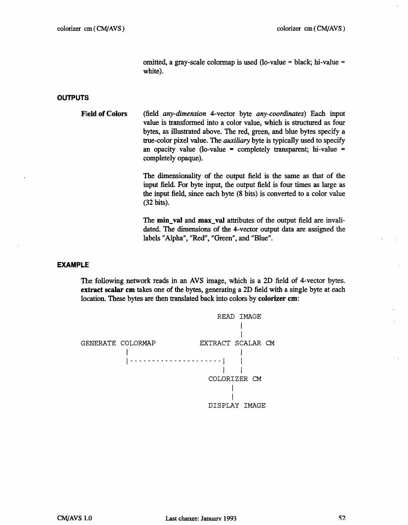
EXAMPLE'
The following network reads in an AVS image, which is a 2D field of 4-vector bytes.extract scalar cm takes one of the bytes, generating a 2D field with a single byte at eachlocation. These bytes are then translated back into colors by colorizer cm:
READ IMAGE
GENERATE COLORMAP EXTRACT SCALAR CM
I
.----- I I
I I
COLORIZER CM
DISPLAY IMAGE
Last change: January 1993
colorizer cm (CNAVS)
I----------------
CM/AVS 1.0 52

colorizer cm (CM/AVS)
RELATED MODULES
Modules that could provide the Data Field input: read volume field to byte Modulesthat could provide the Color Map input: generate colormap Modules that could be usedin place of colorizer cm: arbitrary slicer Modules that can process colorizer cm output:alpha blend gradient shade display image tracer
SEE ALSO
Many of the AVS example scripts demonstrate the AVS colorizer module.
T m.t P'ehno.-- Tanniarv 1 Q.o
colorizer cm (CW/AVS)
IC2"MIAV.R 1 n

combine scalars cm (CM/AVS)
NAME
combine scalars cm - combine scalar fields into a vector field
SUMMARY
combine scalars cm
filter
field any-dimensionoptional)
field any-dimensionoptional)
field any-dimensionoptional)
field any-dimensionoptional)
scalar any-data any-coordinates (channel 0 -
scalar any-data any-coordinates (channel 1 -
scalar any-data any-coordinates (channel 2 -
scalar any-data any-coordinates (channel 3 -
field same-dimension 1D-4D same-data
Parameters NameVector
Type
LenDefaultDial
Min Max4 14
DESCRIPTION
The combine scalars cm module combines up to four fields with scalar data values into afield whose data values are vectors. The input field must be of like dimension and thescalar values must be of the same type.
This module is generally most useful for constructing images or gradient fields from sep-arately computed components.
The input ports on this module's Network Editor icon are processed right-to-left: therightmost port contributes a value to the first element (lowest memory location) of eachoutput vector; the leftmost port contributes a value to the last element (highest memorylocation) of each output vector.
If the selected scalars have labels and/or units associated with them, those labels will becarried over to the newly constructed vector.
INPUTS
None of the input fields is absolutely required, but at least one of them must be provided.If an input field is omitted, zero values may be output in the corresponding element ofeach output vector, depending on the vector dimension set by Vector Length.
Last chanre: O)ctnher 19Q2
Name
Type
Inputs
Outputs
combine scalars cm (CNVAVS)
CM/AVS 1.D 54

combine scalars cm (CM/AVS)
(optional; field any-dimension scalar any-data any-coordinates) Therightmost input port. A set of values to be output in thefirst dimen-sion of the output vectors.
(optional; field any-dimension scalar any-data any-coordinates) Aset of values to be output in the second dimension of the output vec-tors.
(optional; field any-dimension scalar any-data any-coordinates) Aset of values to be output in the third dimension of the output vec-tors.
(optional; field any-dimension scalar any-data any-coordinates) Theleftmost input port. A set of values to be output in the fourth dimen-sion of the output vectors.
Vector Length
Field
Specifies the dimension of the output vectors- 1 - 4.
(field same-dimension 1D-4D same-data) The scalar input streamsare assembled into a single output stream consisting of vectors,whose dimension is specified by Vector Length. The coordinatetype (e.g. uniform, rectilinear, or irregular) of the output field is thesame as the leftmost, non-empty input field. The field's min_val,max_val, veclen, label, and unit are updated.
EXAMPLE 1
The following network performs contrast stretching on only the red band of an image.
READ IMAGE
EXTRACT SCALAR CM[red]
I
CONTRAST CM
I
EXTRACT SCALAR CM[green]
EXTRACT SCALAR CM[blue]
I
I
I I I
COMBINE SCALARS CM (channel 0 not used)
DISPLAY IMAGE
T I,+ 4airo-.k. . m u.l.,- 1 00
Channel 0
Channel 1
Channel 2
Channel 3
PARAMETERS
OUTPUTS
combine scalars cm (CWAVS)
t1-! AX 1 n

combine scalnrs cm(CM/AVS)
EXAMPLE 2
The following network swaps the green and blue bands of an image:
READ IMAGE
I
I
EXTRACT SCALAR [CM][red]
I
EXTRACT SCALAR[green]
I I
I / ---- I
I I ICOMBINE SCALARS
[CM] EXTRACT SCALAR[blue]
I
I
CM
DISPLAY IMAGE
RELATED MODULES
extract scalar cm
SEE ALSO
Tile AVS example script CONTRAST demonstrates the AVS combine scalars module.
Last change: October 1992
[CM]
combine scalmr cm (CM/AVS)
I
CM/AVS 1.0 56

compare field cm (CM/AVS)
NAME
compare field cm - compare two fields, display and write data difference
SUMMARY
Name compare field cm
Type data output
Inputs field any-dimension n-vector any-data any-coordinatesfield same-dimension same-vector same-data same-coordinates
Outputs none
Parameters NameDo CompareMax ElementsOutput File
Type
oneshotintegertypein
Defaultoff100
/tmp/cfield_...
Min Max
1 1000
DESCRIPTION
The compare field cm module compares any two identically-structured AVS fields. Itrill print out differences between the headers if they are different. If the headers are the
same, it will proceed to do a comparison of the data contents of the two fields. If thefields are not identical in their data components, compare field cm will print the mes-sage, "fields are DIFFERENT", to standard output.
The output of the compare is a list of up to Max Elements data differences. The resultsof the compare are both displayed in an Output Browser widget in the control panel andvnritten to a file.
The Output Browser in which compare field cm displays its output can be resized, likeany other widget, using the AVS Layout Editor. For a detailed description of how to dothis, see the section titled "Layout Editor," in the chapter "Advanced Network Editor" ofthe AVS User s Guide.
compare field cm was originally written to make sure that two identical modules, onewritten in C and one written in Fortran, produced the same results. It could also be usefulto compare the contents of a field before and after an operation has been performed on it.
INPUT
Input Field 1 (required; field any-dimension n-vector any-data any-coordinates)The input field can be 1, 2, 3, or 4 dimensional; it can be vector orscalar, can contain byte, int, float or double data, and can have uni-form, rectilinear, or irregular coordinates.
C7
compare field cm (CNVAVS)
._. _ _ . Xr

compare field cm (CM/AVS)
Input Field 2 (required; field any-dimension n-vector any-data any-coordinates)The second input field must match the first in the number of dimen-sions (Ndim), the size of each dimension (Dims), the number ofcoordinate dimensions (Nspace), the vector length (Veclen), the datatype (byte, float, double, etc.), and the type of coordinate system(uniform, rectilinear, curvilinear), if a comparison of the two fields'data is to be done.
Do Compare
Max Elements
Output File
A oneshot "do it now" switch that triggers the actual comparisonafter both input fields exist.
An integer dial that controls how many of the data differences todisplay in the Output Browser and write to the output file. Theallowable range is -1 (none) to 1000. The default is 100. comparefield cm compares the entire fields, until this limit is reached.
An ASCII typein for specifying the output file. By default, com-pare field cm writes to a file in the/tmp directory called cfieldnnnn(where nnn is the process id of the compare field cm module. TheOutput File is rewritten whenever any of the other parameters orinput files change. Since the Output Browser is limited in size, thisoutput file can be useful to examine directly, using a conventionaltext editor.
EXAMPLE 1
The following network reads an image into an AVS field. One version of the image goesdirectly to compare field cm, the other is passed through a threshold cm filter. The"before" and "after" images are compared and the different alpha, red, green, blue valuesat each pixel are listed.
READ IMAGE…I-- - - - - - -
THRESHOLD CM
I
ICOMPARE FIELD CM
Last change: January 1993
PARAMETERS
compare field cm (CM/AVS)
I
I
58CM/AVS 1.0

compare field cm (CM/AVS)
RELATED MODULES
print field
LIMITATIIONS
compare field cm writes to/tmp by default. This can cause problems if: (1) there is no/imp mounted on your system, or (2) the/tmp directory does not have very much room init or has inaccessible protections.
SEE ALSO
The AVS example script COMPARE FIELD demonstrates the AVS compare field mod-ule.
Last chante: January 1993
compare field cm (CM/AVS)
59'fAXJ I n

compute gradient cm ( CM/AVS)
NAME
compute gradient cm - compute gradient vectors for 2D or 3D data set
SUMMARY
compute gradient cm
filter
field 2D/3D scalar byte any-coordinates
field same-dimension 3-vector real same-coordinates
Parameters Name2D HeightFlip
Type
floattoggle
Default0.5on
Min Max0.0 1.0off on
DESCRIPTION
The compute gradient cm module computes the gradient vector at each point in a 2D or3D field of data. The gradient is can be used (e.g. by gradient shade) as a "pseudo sur-face normal" at each point.
A "nearest neighbor" approach is used to compute the gradient: in each direction, thecomponent of the gradient vector is the difference of the next data and the previous data.In two dimensions, this can be pictured as follows:
Y-1 I
I
X,Y-1 I
Y I X-1,Y I
I I
I I
Y+1 I I
X, Y I X+1,Y I
X,Y+1 I
X-1 X X+1
Delta x[X] [Y]Delta_y [X] [Y]
= data[X-l] [Y]= data[X] [Y-l]
- data[X+1] [Y]
- data[X] [Y+1]
Delta z[X] [Y]Delta_z [X] [Y]
= 2D Height Dial[ZI = data[X] [Y] [Z-1] - data[X] [Y] [Z+1]
for 2D datafor 3D data
Last change: January 1993
Name
Type
Inputs
Outputs
compute grasdient cm (CMAVS)
CM/AVS 1.0 60

compute gradient cm ( CM/AVS)
lhis is backwards from the standard definition of a gradient which usually subtracts theprevious value from the next. This was done because the standard definition yields gradi-ents in which the Z componant will typically point in the negative direction. While thestandard definition is better known, the definition of "gradient" as used by this moduleproduces more useful images since the Z componant of the gradient now points towardsdithe eye instead of away from it. However, for the purists, there is a button called Flip (onby default) which lets you disable this "feature" and produce a typical gradient.
This module is slightly different from the vector grad module in a second respect. Sincethe intent of this module is to produce gradients useful to lighting calculations, the vec-tors are automatically normalized.
INPUTS
Data Field (required; field 2D/3D scalar byte any-coordinates) The input fieldmay be either 2D or 3D. The data at each point of the field must bea single byte. The byte values will be interpreted as integers in therange 0..255.
PARAMETERS
2D Height (appears for 2D data only) Supplies the Z-coordinate of the gradient.It can be used to change the apparent height of the surface. A valueof 1.0 is generally a very "rough" or "noisy" surface, whereas valuesapproaching 0.0 will show little effect for shading.
Flip This toggle (on by default) causes the "correct" gradients to beflipped so that the Z axis generally points towards the eye, makinggradients which are more useful for computing lighting calculations.If the "real" gradient is desired, then this button can be turned offand the gradients will not be flipped.
OUTPUTS
Data Field (field same-dimension 3-vector real same-coordinates) The outputfield has the same dimensionality as the input field. For each ele-ment, the output data is a 3D vector of reals, representing the 3Dgradient.
The min_val and max_val attributes of the output field are invali-dated.
TI Iat chnnae.- Tnsmlrv 1993
compute gradient cm (CM/AVS)
61fMIAV. I n

compute gradient cm ( CM/AVS)
EXAMPLE 1
lThe following network shades a 2D image:
READ IMAGE
EXTRACT SCALAR CM I
I I
COMPUTE GRADIENT CM I
I I
I I
GRADIENT SHADE
I
DISPLAY IMAGE
(choose 1 (= red))
EXAMPLE 2
The following network fragment shows how to get the same results as compute gradientusing other modules:
READ FIELD
FIELD TO FLOAT
VECTOR GRAD
FIELD MATH (multiply by -1.0)
VECTOR NORM
EXAMPLE 3
The following network shades a 3D image:
Last change: January 1993
compute gradient cm (CM/AVS)
62CM/AVS 1.0
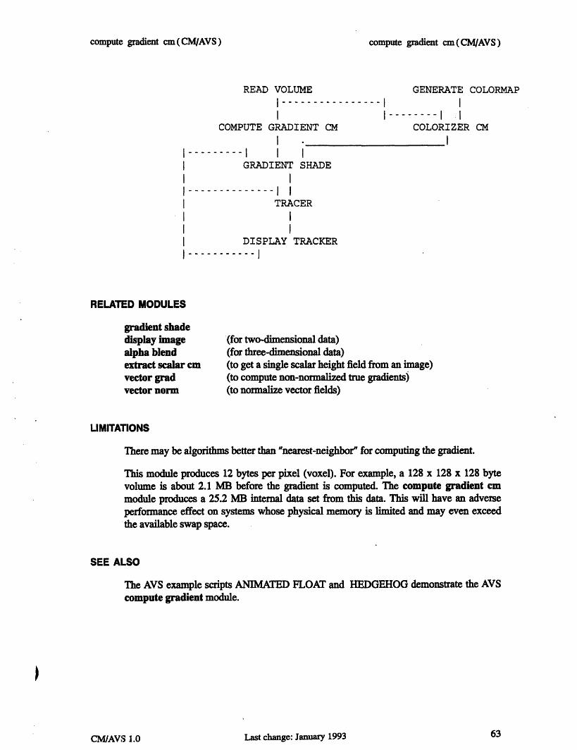
compute gradient cm(CM/AVS)
READ VOLUME
I I
COMPUTE GRADIENT CM
I
....I I I
GRADIENT SHADE
I…"
GENERATE COLORMAP …l ~~~~~I ~~I-- COLORIZER CM
COLORIZER CM
I
…...... I I
TRACER
DISPLAY TRACKERI l- I
RELATED MODULES
gradient shadedisplay imagealpha blendextract scalar cmvector gradvector norm
(for two-dimensional data)(for three-dimensional data)(to get a single scalar height field from an image)(to compute non-normalized true gradients)(to normalize vector fields)
LIMITATIONS
There may be algorithms better than "nearest-neighbor" for computing the gradient.
This module produces 12 bytes per pixel (voxel). For example, a 128 x 128 x 128 bytevolume is about 2.1 MB before the gradient is computed. The compute gradient cmmodule produces a 25.2 MB internal data set from this data. This will have an adverseperformance effect on systems whose physical memory is limited and may even exceedthe available swap space.
SEE AL.SO
The AVS example scripts ANIMATED FLOAT and HEDGEHOG demonstrate the AVScompute gradient module.
63Last change: January 1993
compute gradient cm(Mh~AVS)
I
I
CM/NAV'3 1.0

contrast cm ( CM/AVS)
NAME
contrast cm - perform linear transformation on range of field values
SUMMARY
Name contrast
Tlype filter
Inputs field any-dimension n-vector any-data any-coordinates
Outputs field of same type as input
Parameters Name Type Default Min Maxcontinmin float 0.0 none nonecont in max float 255.0 none nonecontLoutmin float 0.0 none nonecontout_max float 255.0 none none
DESCRIPTION
The contrast cm module transforms all the values in a field. Two different types oftransformation take place:
o Linear transform: All values that fall within the "input range" specified by thecontjin_min and continmax parameters are transformed linearly to the "out-put range" contout_min.. cont_out_max.
(contoutmax - contout min) * (value -continmin)new-value --------------------------------
(cont_in_max- contin_min)
(More precisely, this is an affine transformation.) In essence, this transforma-tion "stretches" or "compresses" one specified range of data to fit another speci-fied range.
o All values that fall outside the specified input range are "clamped" to the limitvalues of the output range.
The contrast cm module typically is used to remove low-level noise from images andvolumes, or to increase the contrast in faded images and volumes.
INPUTS
Data Field (required; field any-dimension n-vector any-data any-coordinates)The input data may be an AVS field of any dimensionality.
Last change: January 1993
contrast cm(CMAVS)
CM/AVS 1.0 64

contrast cm ( CM/AVS)
PARAMETERS
cont_inmin
cont_in_max
cont out min
contoutmax
Specifies the bottom of the range of input values that will betransformed linearly.
Specifies the top of the range of input values that will be trans-formed linearly.
Specifies the bottom of the range of output values. All values contjinmin will be transformed to this value.
Specifies the top of the range of output values. All values cont_in_max will be transformed to this value.
Data Field The output field has the same dimensionality and type as the inputfield.
If the input field has byte values, appropriate new min_val and max_val values are writ-ten to the output field.
EXAMPLE 1
The following diagram shows how field values are transformed given these parameters:
cont in min 100cont in_max - 500contout min - 3000conLouLmax - 6000
Outputs
6000 - - - -
I I
I I
I I
I I3000 xxxxxxxx - -
I I
I I
I I
I I
------ 0I--100
-...............---..--- xxxxx xxxxxxxxxxxx I
xx
xI -
I
500Inputs
65Last change: January 1993
OUTPUTS
contrast cm(CW/AVS)
I I
I
CM/AVS 1.0

contrast cm (CM/AVS)
You can use contrast cm to make a negative out of an image by "flipping" the output val-ues (e.g. cont_outmin - 255; contoutmax = 0).
EXAMPLE 2
The following network reads in an image, extracts the red, green and blue channels, con-trast stretches only the red channel, and then uses combine scalars to pack the seperatechannels back into an image.
READ IMAGE
I
I ............ ............EXTRACT
SCALAR CM
I
EXTRACTSCALAR CM
I II - - - - - - - - - - - - - - - - - - - - - -I - - - - - -
EXTRACTSCALAR CM (red)
I
CONTRAST CM
I................ I
COMBINE SCALARS CM
I
DISPLAY IMAGE
RELATED MODULES
Modules that could provide the Data Field input:
read volume
SEE ALSO
The AVS example script CONTRAST demonstrates the AVS contrast module.
Last change: January 1993
contrast cm (CM/AVS)
I
CM/AVS 1.0 66

downsize cm (CM/AVS)
NAME
downsize cm - reduce size of data set by sampling
SUMMARY
Name downsize cm
Type filter
Inputs field 2D/3D n-vector any-data any-coordinates
Outputs field of same type as input
Parameters Name Type Default Min Maxdownsize integer 8 1 16
DESCRIPTION
The downsize cm module changes the size of the input data set by subsampling the data.It extracts every nth element of the field along each dimension, where n is the value of thedownsize factor parameter. This technique preserves the aspect ratio of the input data.
This module is useful for operating on a reduced amount of data, in order to adjust otherprocessing parameters interactively, or save memory. After the parameter values havebeen set, you can remove the downsize cm module, so that the full data set is used forfinal processing.
Alternatively, retain the downsize cm module in the network, so that you can interac-tively choose between image quality (downsize factor 1 for highest-resolution data)and execution speed (downsize factor > 1 for lower-resolution data).
INPUTS
Data Field (required; field 2D/3D n-vector any-data any-coordinates)The input data may be any AVS field.
PARAMETERS
downsize Determines how data elements from the field are sampled. Increas-ing this parameter causes more elements to be skipped over, thusdecreasing the size of the output.
67Last change: October 1992
downsize cm (CM/Avs)
CM/AVS 1.0

downsize cm (CM/AVS)
OUTPUTS
Data Field The output field has the same dimensionality as the input field, butthe number of elements in each dimension is reduced by the down-size factor.
The min val and max_val attributes of the output field are invali-dated. Note that the extent is unmodified; this module changes theresolution of the data within the physcial space delimited by theextents. It does not alter the physical extents of the data.
EXAMPLE
The following diagram shows how a downsize factor of 4 reduces a 2D field. Each ele-ment of the field is represented by a hyphen or an o. Only the o's are included in the out-put field.
- - -
0
0
0
o - - - - - --- 0
o - - -0 - - -0
o - - - 0 - - - O
o - - --- -0LIMITATIONS
downsize cm works for 2D, and 3D data sets only.
RELATED MODULES
Modules that could provide the Data Field input:
read volumeread fieldfilter modules
Last change: October 1992
downsize cm(CWyAVS)
68CM/AVS 1.0

downsize cm (CM/AVS)
SEE ALSO
The AVS example scripts FIELD MATH, and GRAPH VIEWER demonstrate the AVSdownsize module.
....... T_~ _l ... T- - Ali t 1I lnl 69
downsize cm (CWyAVS)
Iasi cmange: u rkwum 1772CM/AVS 1.0

extract scalar cm (CMAVS)
NAME
extract scalar cm - extract a scalar field from a vector field
SUMMARY
Name extract scalar cm
Type filter
Inputs field any-dimension n-vector any-data any-coordinates(n- 1..25)
Outputs field same-dimension scalar same-data same-coordinates
Parameters NameChannel n
Type Defaultradio buttons Channel 0
DESCRIPTION
The extract scalar cm module inputs a field whose data values are vectors (1D to 25D),and outputs one of the dimensions ("channels") as a scalar-valued field. The output fieldhas the same structure as the input field, except that its data values are scalars (vectorlength of 1).
This module is useful for performing operations on individual channels of vector fields. Itis frequently used with the combine scalars cm module, which composes vector fieldsfrom individual scalar fields.
INPUTS
Data Field
Channel n
(required; field any-dimension n-vector any data any-coordinates)The input data may be any field whose data values are vectors with25 or fewer dimensions. Even scalar fields may be used, since theirdata values are considered to be 1D vectors.
Selects the dimension of the input data values to be output. A set ofradio buttons appears, showing the labels that are attached to thedimensions of the n-vector data.
Last change: October 1992
PARAMETERS
extract scalar cm ( CAVS )
CM/AVS 1.0 70

extract scalar cm (CM/AVS)
OUTPUTS
field (same-dimension scalar same-data same-coordinates)The output field has the same dimensionality as the input field. Thedata for each element is reduced from a vector to a scalar. Theveclen, min_val, max_val, label, and unit values in the field areupdated.
EXAMPLE 1
This examples displays a slice of the Y-component of the gradient field of a volume:
READ VOLUME
ICOMPUTE GRADIENT
EXTRACT SCALAR CM [1] (O=X, =Y, 2=Z)
ORTHOGONAL SLICER CM
I
GENERATE COLORMAP FIELD TO BYTE CM
COLORIZER CM
I
DISPLAY IMAGE
For additional examples, see the combine scalars cm manual page.
RELATED MODULES
combine scalars cm
SEE ALSO
The AVS example scripts CONTOUR GEOMETRY, CONTRAST, as well as othersdemonstrate the AVS extract scalar module. The extract scalar cm module may be sub-stituted in many of these examples.
extract scalar cm(CNVAVS)

fft cm(CM/AVS)
NAME
St cm - do a Fast Fourier Transform on a field
SUMMARY
Name
lpeInputs
Outputs
P;m-rameters
fft cm
filter
field float (each axis must be length power of two)
field
op
DESCRIPTION
The fit cm module takes a floating point 11213 D 2-vector and, depending on the op"parameter, does either a forward or inverse Fast Fourier Transform on it. The moduleuses the simple FFT routine in the Thinking Machines CMSSL library.
INPUTS
field
field
(required; field ID, 2D, or 3D 2-vector float)The field to be transformed.
(required; field ID, 2D, or 3D 2-vector float)The transformed field.
EXAMPLE
The following network reads an image, crops it to dimensions which are a power of two,pulls out a 2-vector, converts it to floating point, does a forward FFT, then an inverseF]er, coverts the data back to bytes, extracts the first channel, and recombines it into agreyscale image, and displays it. The result should be the greyscale equivalent of the firstextracted channel of the image.
Last change: October 1992
OUTPUTS
Mf cm (CM/VS)
CM/AVS 1.0 72

fft cm(CM/AVS)
READ IMAGE
CROP
EXTRACT VECTOR
FIELD TO FLOAT CM
FFT CM (forward)
FFT CM (inverse)
FIELD TO BYTE CM
EXTRACT SCALAR CM
COLORIZER CM
IMAGE VIEWER
RELATED) MODLILES
Modules that could provide the field input:
read field
Modules that can process fft cm output:
write fieldimage viewerdisplay image
Mf cm(CNAVS)

field math cm ( CM/AVS )
NAME
field math cm - perform math operations between fields
SUMMARY
Name field math cm
Type filter
Inputs field any-dimension n-vector any-data any-coordinatesfield same-dimension same-vector any-data same-coordinates(OPTIONAL)
Outputs field same-dimension same-vector any-data same-coordinates
ParametersName Type Default Min Maxchoice choice +Normalize boolean offConstant float typein 0.0 unbounded unbounded
DESCRIPTION
The field math cm module performs unary and binary operations upon parallel fields.
Thle unary operations are Not, Square, and Sqrt. The binary operations are +, -, *, /, And,OI, Xor, Left-Shift, Right-Shift, and RMS (Root Mean Square). Unary operations are per-formed against the right port field only. The field that is connected to the left port isignored. If only one field is provided as an operand for a binary operations, the field mustbe attached to the right port and the binary operations are performed on the right portfield and the Constant input parameter.
When two fields are connected to the module, the Constant parameter is not displayedand the fields are evaluated against each other.
ThTe input fields must be of the same dimensionality, size, and vector length. When thefields contain different data types, the output field will have the more elaborate data type.
When the fields have different coordinate types, the output field will have the same coor-dinate type as the right input port field.
During computation, byte data is converted to integer, while short, integer, and float dataare converted to double. The result is then converted back to the appropriate output datatype. If Normalize is off, the data is "clamped" to the range:
0.. .255] byte[-32767.. .32767] short[-2147483647.. .2147483647] integer
Last chanae: Jamntrv 19934
field math cm (CMIAVS)
CM/AVS 1.0 74

field math cm (CM/AVS)
If Normalize is on, the result is normalized to between:
255]
32767]
2147483647]1]
byteshor tintegerfloat, double
(required; field any-dimension n-vector any-dataany-coordinates)The rightmost input field is used as the input to unary operations, orthe first operand for binary operations.
(optional; field same-dimension same-vector any-datasame-coordinates)The left field is the second operand in binary operations. It musthave the same dimension, size, and vector length as the first inputfield.
Or (bitwise)
Xor (bitwise)
Not (bitwise)
Left-Shift (bitwise)
Right-Shift (bitwise)
Square
Sqrt
RMS (Root Mean Square)A choice of operations. For binary operations, if the left port field (field2) is not pro-vided, the Constant parameter is used as the second operand (i.e. field2 is replaced by
75
o 0...[0...[0...
[0...
INPUTS
Data Field
Data Field
PARAMETERS
.I
*
And (bitwise)
field math cm (CW/AVS)
. ... _ T .. , 1 on

field math cm (CM/AVS)
Constant).
AndOr
XorNotLeft-ShiftRight-ShiftSquareSqrtRMS
fieldi + field2fieldi - field2fieldi * field2fieldi / field2fieldi AND field2fieldl OR field2fieldi XOR field2NOT fieldifieldi << field2fieldl >> field2field * fieldisqrt (fieldl)sqrt (fieldl**2 +
(result is 0 if field2 is 0)
Inot applicable forIfloats and doubles
field2**2)
Normalize
Constant
OUTPUTS
I)ata Field
EXAMPLE I
Selecting Normalize causes the results of the operation to be nor-malized to between 0 and 1 for floats and doubles, 0 and 255 forbytes, 0 and 32767 for shorts, and 0 and 2147483647 for integers.Normalize is off by default.
A floating point typein to specify the constant value to use as thesecond operand in binary operations. If two fields are connected tothe module, Constant is ignored and disappears from the controlpanel. The default is 0.0. There is no upper or lower limit.
(field same-dimension same-vector any-data same-coordinates)The output field has the same form as the input fields.If the input fields were of different data types, the output fieldwill have the more elaborate data type. If the input fields haddifferent coordinate types, the output field will have the samecoordinate type as the right input port field.
The following network inverts (flips the look-up table) an image using the Not function,with Normalize on. The same effect can be achieved by multiplying the image by -1.
READ IMAGE
FIELD MATH CM
IDISPLAY IMAGE
Last change: January 1993
field math cm (CM/yAVS)
76CM/AVS 1.0

field math cm (CM/AVS)
EXAMPLE 2
'Ihis network does a logical AND on a volume against the constant 128 (0x80), whichproduces a volume with only Os and 255s based on whether the source voxel was greateror less than 128.
READ VOLUME
I
FIELD MATH CM
I
ORTHOGONAL SLICER CM
COLORIZER CM
DISPLAY IMAGE
RELATED MODULES
Modules that could provide the Data Field inputs:
Any module that outputs a field
Modules that can process field math cm output:
Any module that inputs a field
SEE ALSO
Two AVS FIELD MATH example scripts demonstrate the AVS field math module.
xAilAV 1 n Last change: January 1993 77
field math cm (CM/AVS)

field to bte cm (CM/AVS)
NAME
field to byte cm - transform any field to a byte-valued field
SUMMARY
Name
Type
hInputs
Outputs
field to byte cm
filter
field any-dimension n-vector any-data any-coordinates
field same-dimension same-vector byte any-coordinates
Namebyte normalize
Type
toggleDefaulton
Choiceson, off
DESCRIPTION
The field to byte cm module takes a field of data (integer, real, double, or byte) and con-verts it to a byte field. It can be used in conjunction with volume visualization modulesthat have a bias towards byte fields (i.e., compute gradient cm).
By default, the input data is normalized to the range 0..255 If the toggle parameterbyte_normalize is turned off, the data is "clamped" to that range instead. (See below fordetails.)
INPUTS
(required; field any-dimension n-vector any-data any-coordinates)The input data may be any AVS field.
byte_normalize This is a toggle parameter:
If on: The data is transformed linearly into the range0..255:
(value - min) * 255newvalue =
max - min
The data is "clamped" so that no value falls outside therange 0..255:
Last change: October 1992
Parameters
Data Field
PARAMETERS
If off:
field to byte cm (CM/AVS)
78CM/AVS 1.0

field to byte cm (CMIAVS)
I f value < 0
If 0 <= value <= 255
If value > 255
new_value O0
new_value - value
new.._value - 255
I)ata Field (field same-dimension same-vector byte same-coordinates)The output field has the same dimensionality as the input field, buteach scalar value is forced to be a byte.
Appropriate new values of the min val and max_val attributes arewritten to the output field.
RELATED MODULES
vIModules that could provide the Data Field input:
read volume
]Modules that could be used in place of field to byte cm:
field to int cmfield to float cmfield to double cm
Modules that can process field to byte cm output:
read volume
SEE ALSO
'The AVS example scripts FIELD TO BYTE and FIELD TO INTEGER demonstrate theAVS field to byte module.
CM/AVS 1.0 Last change: October 1992 79
OUTPUTS
field to byte cm (CM/AVS)

field to double cm(CM/AVS)
NAME
Name
Type
Inputs
Outputs
double cm - transform any field to a field of double-precision floating point val-
field to double cm
filter
field any-dimension n-vector any-data any-coordinates
field same-dimension same-vector double same-coordinates
ParametersNamedouble normalize
Typetoggle
Defaulton
Choiceson, off
DESCRIPTION
The field to double cm module takes a field of data (byte, real, double, or integer) andconverts it to an double field. This may be useful for computing fields at greater data res-olutions.
By default, the input data is simply cast (re-typed) to be double-precision floating point.If the toggle parameter double_normalize is turned on, the data is also normalized to therange 0..1. (See below for details.)
INPUTS
I)ata Field (required; field any-dimension n-vector any-data any-coordinates)The input data may be any AVS field.
double_normalize This is a toggle parameter:
If on: The data is transformed linearly into the range O..1:
new value =(value - min)
max - min
The data is converted to double-precision floatingpoint format.
Last change: October 1992
field toues
SUMMARY
PARAMETERS
If off:
field to double cm (CNVAVS)
CM/AVS 1.0 80

field to double cm(CM/AVS)
OUTPUTS
Data Field (field field same-dimension same-vector double same-coordinatesThe output field has the same dimensionality as the input field, buteach scalar value is forced to be a double-precision number.
Appropriate new values of the min_val and max_val attributes arewritten to the output field.
RELATED MODULES
read volumefield to byte cmfield to int cmfield to float cm
SEE ALSO
The AVS example script FIELD TO INTEGER demonstrates the AVS field to doublemodule.
Last change: October 1992
field to double cm (CM/AVS)
CM/AVS 1.0 81

field to float cm(CM/AVS)
NAME
field to float cm - transform any field to a field of single-precision floating point values
SUMMARY
field to float cm
filter
field field any-dimension n-vector any-data any-coordinates
field same-dimension same-vector float same-coordinates
ParametersNamefloat normalize
Typetoggle
Defaultoff
Choiceson, off
DESCRIPTION
The field to float cm module takes a field of data (byte, short, real, double, or integer)anid converts it to a float field. It can be used in conjunction with modules that have abias towardsfloat fields (particle advector, samplers).
By default, the input data is simply cast (re-typed) to be single-precision floating point. Ifthe toggle parameter float normalize is turned on, the data is also normalized to the rangeO..1. (See below for details.)
INPUTS
(required; any-dimension n-vector any-data any-coordinates)The input data may be any AVS field.
This is a toggle parameter:
If on: the data is transformed linearly into the range 0.. 1:
new value =(value - min)
max - min
the data is converted to single-precision floating pointformat.
Last change: January 1993
Name
Type
Inputs
Outputs
Data Field
PARAMETERS
float normalize
If off:
field to float cm(ChyAVS)
CM/AVS :1.O 82

field to float cm (CM/AVS)
OUTPUTS
Data Field (field same-dimension same-vector float same-coordinatesThe output field has the same dimensionality as the input field, buteach scalar value is forced to be a single-precision number.
Appropriate new values of the min_val and max_val attributes arewritten to the output field.
RELATED MODULES
read volumeparticle advectorsamplersfield to byte cmfield to shortfield to int cmfield to double cm
SEE AL'SO
The AVS example script FIELD TO INTEGER demonstrates the AVS field to float mod-ule.
LIMITATIONS
Overflow or underflow may occur when converting a double field to a float field withfloat normalize turned off.
83
field to float cm(CNVyAVS)
Last change: January x::,M/AV. 1 n

field to int cm(CM/AVS)
NAME
field to int cm - transform any field to an integer-valued field
SUMMARY
field to int cm
filter
field any-dimension n-vector any-data any-coordinates
field same-dimension same-vector integer same-coordinates
Parameters Nameint normalize
DESCRIPTION
The field to int cm module takes a field of data (byte, short, real, double, or int) and con-verts it to an int field. This may be useful for performing integer math with greater preci-sion (-231-1 to 231-1, -2147483647...2147483647) than that offered by byte fields(0..255).
By default, the input data is "clamped" to the range -231-1...231-1. If the toggle parame-ter intnormalize is turned on, the data is normalized to 0...231-1 instead. (See below fordetails.)
INPUTS
Data Field (required; field any-dimension n-vector any-data any-coordinates)The input data may be any AVS field.
int normalize This is a toggle parameter:
If on: the data is transformed linearly into the range0..231-1:
new value =(value - min) * 2147483647
max - min
Last change: January 1993
Name
1ype
Inputs
Outputs
togglpe
toggleDefaulton
Choiceson, off
PARAMETERS
field to int cm (CM/rAVS)
CM/AVS 1.0 84

field to int cm(CM/AVS)
the data is "clamped" so that no value falls outsidethe range -2147483647...2147483647. Valuesgreater than 2147483647 are set to 2147483647.Values less than -2147483647 are set to-2147483647.
(field same-dimension same-vector integer same-coordinates)The output field has the same dimensionality as the input field, buteach scalar value is forced to be an integer.
Appropriate new values of the min.val and max val attributes arewritten to the output field.
RELATED MODULES
field to byte cmfield to shortfield to float cmfield to double cm
SEE AILSO
The AVS example script FIELD TO INTEGER demonstrates the AVS field to int mod-ule.
Last chance: January 1993
If off:
OUTPUTS
Data Field
field to int cm (CNAVS)
tMAV.R n 85

luminance cm ( CM/AVS)
NAME
luminance cm - compute the luminance of an image
SUMMARY
Name
Type
Inputs
Outputs
Parameters
luminance cm
filter
field 2D uniform 4-vector byte (image)
field 2D uniform scalar byte
none
DESCRIPTION
The luminance cm module computes the luminance (brightness) of an image, then out-puts a 2-dimensional field of the same dimensions, but with a scalar byte value for eachpixel in the original image instead of the full four-byte alpha, red, green, blue vector.
The luminance (I) is calculated as follows:I = (0.299 * red) + (0.587 * green) + (0.114 * blue)
This luminance byte value can be used to produce a black and whitenal image (with colorizer cm), or substituted back into the alphaimage (with replace alpha) to produce transparency effects.
version of the origi-byte of the original
(required; field 2D uniform 4-vector byte)The image whose luminance to calculate.
(field 2D uniform scalar byte)The output field has the same dimension as the input image, butwith a scalar byte value representing the image luminance at eachoriginal pixel instead of color value.
EXAMPLE 1
Tihe following network reads an image, computes its luminance, colorizes the resultingfield with the default black and white colormap, producing a black and white version ofthe original image. The result is displayed through the image viewer.
Last change: October 1992
INPUTS
Image
OUTPUTS
Data Field
luminance a (CWAVS)
86CM/AVS 1.0

luminance cm (CMIAVS) luminance cm (CM/AVS)
READ IMAGE
ILUMINANCE CM
ICOLORIZER CM
IIMAGE VIEWER
EXAMPLE 2
This network takes a geometry, displays it on the screen, then converts the screen pixmapto an image, computes its luminance, uses that to create an alpha mask, renders a shadedbackground and composites the rendered image over the shaded background. The con-I:trast modules controls should be set to : minimum and maximum input contrast, both 1;minimum output contrast 0, and maximum output contrast, 255. If the original geometrywere /usr/avs/data/geometry/jet. geom and the background module were set to produce asky-like pattern, this would produce a jet over a sky field.
READ GEOM
IGEOMETRY VIEWER
.i
DISPLAY IMAGEI
BACKGROUND
I
LUMINANCE
ICONTRAST C
I----
CM I
]M
-- I IREPLACE ALPHA
--- I I
COMPOSITE
IMAGE VIEWER
RELATED MODULES
Modules that could provide the Image input:
Any module that produces an image as output
Last change: October 1992r'UAIAVq I n87
-
I-------------------

luminance cm( CM/AVS)
Modules that can process luminance cm output:
colorizer cmcontrast cmAny modules that can process a 2D scalar field
Other related modules:backgroundcompositereplace alphaextract scalar cm
SEE ALSO
The AVS example script LUMINANCE demonstrates the AVS luminance module.
Last change: October 1992CM/AVS .0 88
luminance cm (CM/AVS)
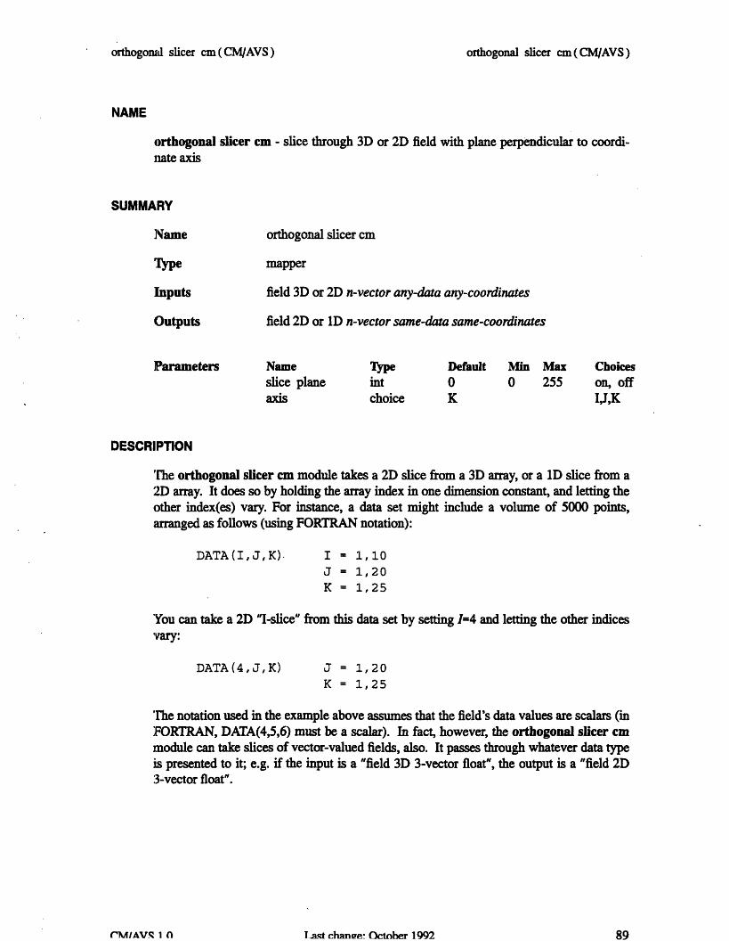
orthogonal slicer cm(CMIAVS)
NAME
orthogonal slicer cm - slice through 3D or 2D field with plane perpendicular to coordi-nrate axis
SUMMARY
Name
Inputs
Outputs
orthogonal slicer cm
mapper
field 3D or 2D n-vector any-data any-coordinates
field 2D or ID n-vector same-data same-coordinates
Parameters Nameslice planeaxis
Type
intchoice
Default0K
Min Max Choices0 255 on, off
I,J,K
DESCRIPTION
'The orthogonal slicer cm module takes a 2D slice from a 3D array, or a D slice from a2D array. It does so by holding the array index in one dimension constant, and letting theother index(es) vary. For instance, a data set might include a volume of 5000 points,arranged as follows (using FORTRAN notation):
DATA(I,J,K)- I = 1,10J = 1,20K = 1,25
'You can take a 2D "I-slice" from this data set by setting 1=4 and letting the other indicesVary:
DATA (4, J, K) J = 1,20K = 1,25
The notation used in the example above assumes that the field's data values are scalars (inFORTRAN, DATA(4,5,6) must be a scalar). In fact, however, the orthogonal slicer cmmodule can take slices of vector-valued fields, also. It passes through whatever data typeis presented to it; e.g. if the input is a "field 3D 3-vector float", the output is a "field 2D3-vector float".
Last chance October 1992
ordiogorud slicer cm (M/AVS)
89rMIV.q n

orthogonal slicer cm ( CM/AVS)
INPUTS
Data Field (field 2D/3D n-vector any-data any-coordinates)The input may be any 3D or 2Dfield.
slice plane
axzis
OUTPUTS
Data Field
Determines the value of the array index to be held constant.value is reset to zero each time a new data field is input.
This
Selects the dimension (1, J, or K) in which the array index is to beheld constant.
(field 1D/2D n-vector any-data any-coordinates)The output field is 2D instead of 3D (or 1D instead of 2D), and hasthe same type of data as the input field.
Appropriate new values for min_ext and max_ext are written to theoutput field.
EXAMPLE 1
The following network takes a slice from a scalar volume and displays it:
READ VOLUME
IORTHOGONAL SLICER CM
GENERATE COLORMAP (optional)
ll----l--------
I ICOLORIZER CM
IDISPLAY IMAGE
The colorizer cm module is necessary because the output of orthogonal slicer cm is a"field 2D scalar byte", which must be cast into an AVS image field for display.
Last change: October 1992
PARAMETERS
orthogonal slicer cm(CNVAVS)
90CM/AVS 11.0

orthogonal slicer cm (CM/AVS)
EXAMPLE 2
For reasonably small volumes, a better way to construct this network is:
READ VOLUME
I GENERATE COLORMAP (optional)I I ….--------------I
I I
COLORIZER CM
ORTHOGONAL SLICER CM
IDISPLAY IMAGE
This network has the effect of colorizing the entire volume once, which make the slicingcperation more efficient. It does this at the expense of allocating more memory up front.
EXAMPLE 3
Irregular Data: orthogonal slicer cm supports the passing of "points" data for rectilin-ear and irregular data. This is an important module for visualizing curved data sets. Forexample:
READ FIELD (irregular data)
I
GENERATEORTHOGONAL SLICER CM
COLORMAP I
VOLUME BOUNDS
I
FIELD TO MESH
GEOMETRY VIEWER
(This is the reason for labeling the axis control with "I, J, and K": frequently, the data istot aligned to the X, Y, and Z axes. orthogonal slicer cm takes slices through the logicaldata set, not the physical one.)
Last change: October 1992
I
orthogonal slicer cm(CM/AVS)
I I
91CM/AVS 1.0

orthogonal slicer cm ( CM/AVS)
EXAMPLE 4
The following network shows how to use orthogonal slicer cm to plot the values of onescan-line of an image:
READ IMAGE
EXTRACT SCALAR CM
ORTHOGONAL SLICER CM (set to middle of image)
GRAPH VIEWER
RELATED MODULES
field to meshcolorizer cm
SEE ALSO
The AVS example scripts ANIMATED INTEGER, COLOR RANGE, and VECTORCURL demonstrate the AVS orthogonal slicer module.
Last change: October 1992
orthogonal. slicer c (CMAVS)
CM/AVS L.0 92

threshold cm (CM/AVS)
NAME
threshold cm - restrict values in data field
SUMMARY
Name
Type
Inputs
Outputs
]Parameters
threshold cm
filter
field any-dimension n-vector any-data any_coordinates
field of same type as input
Name Type Default Minthresh min float 0.0 nonethreshmax float 255.0 none
DESCRIPTION
The threshold cm module transforms the values of a field as follows:
o Any value less than the value of the threshold_min parameter is set to 0.
o Any value greater than the value of the threshold_max parameter is set to 0.
o Values within the threshold_min-to-threshold_max range are not changed.
After being threshold'ed, a data set's values are all either zero, or in this range:
threshmin <= value <= thresh max
Note the difference between the clamp cm and the threshold cm modules:
o threshold cm sets values outside the specified range to be zero.
o clamp cm sets values outside the specified range to be the range's minimumand maximum values.
INPUTS;
Data Field (required; field any-dimension n-vector any-data any_coordinates)The input data may be any AVS field.
Last change: October 1992
Maxnonenone
threshold cm(CM/AVS)
93CM/AVS 1.0

threshold cm ( CM/AVS)
PARAMETERS
threshmin
threshmax
OUTPUTS
Field Data
The minimum threshold value.
The maximum threshold value.
The output field has the same dimensionality as the input field.
Appropriate new values of the minval and max_val attributes arewritten to the output field.
RELATE[) MODULES
lModules that could provide the Data Field input:
read volumeany otherfilter module
Modules that could be used in place of threshold cm:
clamp cm
Modules that can process threshold cm output:
colorizer cmany other filter module
SEE ALSO
The AVS example scripts CONTOUR GEOMETRY, and THRESHOLDED SLICERdemonstrate the AVS threshold module.
Last change: October 1992
threshold c (MPAVS)
94CM/AVS 1.0

Appendix C
Unsupported Programs and Modules
This appendix contains information about programs and modules that areincluded with CWMAVS but are not guaranteed or supported.
These items reside in the directory /usr/ezamples/cmavs/unsuppozted.
C.1 Programs
The following programs are documented in this appendix:
avstoppm
ppmtoavs
C'.2 Modules
The following modules are documented in this appendix:
field to polygons
field to spheres
Version 1.0, February 1993Copyright 0 1993 Thinking Machines Corporation 95

I
avstoppm ( CM/AVS Unsupported)
NAME
avstoppm - convert AVS images (.x format) to PPM format
SYNOPSIS
avstoppm [ infie ] [ ouile ]
DESCRIPTION
avstoppm converts images from AVS format (filenames end in .x) to PPM format. If nofilenames are given, avstoppm reads from stdin and writes to stdout. If one filename isgiven, it is the input filename, and output goes to stdout. If two filenames are given, thefirst is the input file and the second is the output file (which is first trunmcated if it exists).
NOTE: The PPM format is part of the pbmplus package. For more information on thepbmplus package, send mail to [email protected] (Jeff Poskanzer); the pbmplus packagecan be retrieved via FTP from archive.cis.ohio-state.edu:publpbmplus/pbmplus.tar.Z,among many other places.
avstoppm resides in Iusrlexampleslcmavs/unsupported.
OPTIONS
There are no options to avstoppm.
SEE ALSO
libppm(3), ppmto...(l) (converters for ppm to many image formats)
DIAGNOSTICS
The diagnostics are intended to be self-explanatory.
BUGS
None known.
Last change: January 1993
avstoppzn(CWrlAVS Unsupported)
CM/AVS 1.0 97

ppmtoavs (CM/AVS Unsupported)
NAME
ppmtoavs - convert PPM format images to AVS images (.x format)
SYNOPSIS
ppmtoavs [ infile] [ ouile ]
DESCRIPTION
ppmtoavs converts images from PPM format to AVS image format. The alpha bytes ofthe AVS image are all zeros (but they can be set to any value within AVS by using thereplace alpha module).
NOTE: The PPM format is part of the pbmplus package. For more information on thepbmplus package, send mail to [email protected] (Jeff Poskanzer); the pbmplus packagecan be retrieved via FTP from archive.cis.ohio-state.edu:Ipub/pbmplus/pbmplus.tar.Z,among many other places.
If no filenames are given, ppmtoavs reads from stdin and writes to stdout. If one file-name is given, it is the input filename, and output goes to stdout. If two filenames aregiven, the first is the input file and the second is the output file (which is first truncated ifit exists).
ppmtoavs resides in /usr/examples/cmavs/unsupported.
OPTIONS
There are no options to ppmtoavs.
SEE ALSO
libppm(3), ppmto...(l) (converters for ppm to many image formats)
DIAGNOSTICS
Tihe diagnostics are intended to be self-explanatory.
BUGS
None known.
Last change: January 1993
ppmtoavs (CAVS Unsupported)
CM/AVS 1,.0 98

field to polygons (CM/AVS Unsupported)
NAME
field to polygons (unsupported) - translates a coordinate field into a set of polygons
SUMMARY
Name
Type
Inputs
]Parameters
field to polygons
mapper
polygon list 2D 3-space irregular floatcolormap Outputs polygon geom (geom)
NameUse Color
Type
toggleDefaultoff
ieldto..polygons resides in usr/examples/cmavs/unsupported.
DESCRIPTION
field to polygons cm translates a field containing vertex coordinates into a geometrydescribing polygons. The polygon list's points array contains the vertex coordinates andthe data array (optionally) contains the color information.
'he Use Color parameter determines how the polygon will be colored. (See below fordetails.)
INPUTS
polygon list
colormap
(required; field 2D 3-space [1 or 3]-vector irregular float)The first dimension of the input field must be equal to the num-ber of sides of the polygons. All polygons must have the samenumber of sides. The second dimension is the number of poly-gons. The points array describes the coordinates of the poly-gons. The data array optionally describes the polygons color.The vector length restriction has effect only if the Use Colorparameter is on.
(colormap)This colormap is used to color the polygons when the Use Colortoggle is on and a 1D data field is suppied. The default colormapis a linear ramp from black to white with a low value of O.Oand ahigh value of 255.0.
Last change: January 1993
Choiceson, off
field to polygons (CM/lAVS Unsupported)
99CMWAVS Unsupported
field to polygons (CM/AVS Unsupported)
OUTPuIrs
polygon geom (geom)The output geometry containing the polygon objects.
PARAMETERS
Use Color This is a toggle parameter:
If on: The polygon vertices will be colored using thefield's data and, optionally, the given colormap.There are two techniques used to color the datadepending on the vector length of the polygonlist. If the vector length is one, the value of eachelement is used as an index into the colormap. Ifthe vector length is three, they are interpreted asthe red, green and blue color values.
If off: (default) The polygons will be drawn withoutexplicit color information. Generally, thisresults in the polygons being drawn in white. Inthis case, the polygon list's data array is ignored.
EXAMPILE
READ FIELD
I
FIELD TO POLYGONS
I
GEOMETRY VIEWER
RELATED MODULES
field to spheres (unsupported)
Last change: January 1993
field to polygons (CNV"S Unsupported)
CW/AVS Unsupported 100

field to spheres (CM/AVS Unsupported)
NAME
field to spheres (unsupported) - translates a coordinate field into a set of spheres
SUMMARY
Name field to spheres
Type mapper
Inputs sphere list - field 3-space irregular floatcolormap - colormap
Outputs sphere geom - geom
Parameters Name Type Default Choicessize dial 0.0Use Color toggle off on, off
field_to_spheres resides in /usrlexamples/cmavslunsupported.
DESCRIPTION
field to spheres translates an irregular field describing a set of three space coordinatesinto a geometry containing sphere objects. The sphere list's points array describes thespheres' positions. Optionally, the field's data array describes the spheres' colors.
IF the size parameter is equal to 0.0, the spheres will be drawn as single pixels. If the sizeis greater than 0.0, the spheres will be drawn as uniformly sized spheres with radii equalto the size.
The Use Color parameter determines how the spheres will be colored. (See below fordetails.)
INPUTS
sphere list (required; field 3-space [1 or 3]-vector irregular float)This field must be a list of irregular points in 3-space. The pointsarray describes the coordinates of the spheres. The data arrayoptionally describes the spheres color. The vector length restric-tion has effect only if the Use Color parameter is on.
colormap (colormap)This colormap is used to color the spheres when the Use Colortoggle is on and a 1D data field is suppied. The default colormapis a linear ramp from black to white with a low value of 0.0 and ahigh value of 255.0.
Last change: January 1993
field to spheres MyAVS Unsupported)
101M~AVS Unsupported

field to spheres (CM/AVS Unsupported)
PARAMETERS
size (dial)The size of the spheres. If equal to zero, the spheres are ren-dered as single pixels. Otherwise, the value is used as the radiusin world coordinates.
Use Color This is a toggle parameter.
If on: The spheres will be colored using the field's dataand, optionally, the given colormap. There aretwo techniques used to color the data dependingon the vector length of the sphere list. If thevector length is one, the value of each element isused as an interpolated index into the colormap.If the vector length is three, the three values areinterpreted as the red, green and blue color val-ues. They should lie in the range from 0.0 to 1.0.
If off: The spheres will be drawn without explicit colorinformation (no color information is encodedwith the sphere data). Generally, this results inthe spheres being drawn in white. In this case,the sphere list's data array is ignored.
OUTPUTS
sphere geom (geom)The output geometry containing the sphere objects.
EXAMPLE
SAMPLERS
IFIELD TO SPHERES
I
GEOMETRY VIEWER
Last change: January 1993
field to sheres (CNVyAVS Unsupported)
102CR[AVS UInsuppoted

field to spheres (CM/AVS Unsupported)
RELATED MODULES
scatter dots
scatter dots is very similar to field to spheres, differing in the following ways:
o The radius of each sphere may be specified independently in scatter dots.
o scatter dots requires more information to be specified per sphere.
o scatter dots is slower.
o scatter dots requires a ID coordinate field, whereas field to spheres isindependent of the field's dimension.
Last change: January 1993
field to spheres( CM/AVS Unsupported)
CM/AVS Unsupported 103


Index::~`:%:~`~::`::::::::::~ ......................... : ':X. ...................................................,.' .'.S...........................................................
Symbols.avsrc file, 7
Aaccess routines
parallel field coordinates, 20parallel field data, 20
arrays, declaring, 23AVS routines
AVSdata_free, 18AVSbuild_2d field, 18
AVSbuild 3d field, 18
AVSbuild_free, 18
AVSdata_alloc, 19
AVSfieldalloc, 18AVSfield copypoints, 18
AVSfield_data_offset, 18AVSfielddataptr, 18
AVSf eld free, 18AVf ield pointsoffset, 18AVSfield points ptr, 18
AVSfield_reset_minma 18AVSset module_flags, 17
avs_dbx, 29
AVSTYPEBYTE, 22
AVsTYPE DoUBLE, 22
AVS TYPE INTEGE, 22AVS TYPE REA 22
AVS_TYPESHORT, 22
AVSbuild2d field, AVS routine, 18
AVSbuild 3d field, AVS routine, 18
AVSbuild field, AVS routine, 18AVscreateinputport, AVS routine, 18AVSdata_alloc, AVS routine, 19AVSdata free, AVS routine, 18AVSfield alloc, AVS routine, 18AVSfieldcopy points, AVS routine, 18AVSfield dataoffset, AVS routine, 18
Version 1.0, February 1993Copyright 1993 Thinking Machines Corporation
AVSfield dataptr, AVS routine, 18AVSfield_free, AVS routine, 18AVSfield ointsoff set, AVS routine,
18
AVSfield points-ptr, AVS routine, 18AVSfieldreset_minmax, AVS routine, 18AVSset_module_flags, AVS routine, 17
B
binary filemulti-module, 19multi-module, 12, 30
Ccleaning up, 14CM/AVS
overview, 1
routines, 1
CM/AVS modules, running locally, 13CM/AVS header file, 27CM/AVS include file, 27CM/AVS libraries, 27CM/AVS modules
list, 5man pages, 41
running remotely, 7CM/AVS routines, 31
CNAVScoroutinit, 32COAVSdata alloc, 18, 19,32CAVSfieldalloc, 18, 19,33CMAVSfield_alloc_data_shape, 34CMAVSfield_allocpoint_sh ape, 35
CMAVSBfieldcopyPoints, 18, 35CNAVSf ield_data_get, 18,20, 36CMAVSfield points_get, 18, 20, 37CMAVSfieldresetminma 18,38
CMAVSisfield _on_C, 39
105

106 ;'\S'.SoS,, XffSSgffSf .x fffSff C/A V;SU ersG id;.e:. x :, f'ff xse26 f'4Xsf::::::: 'fs'Sf M........... ..... .. .. .. . ...... ...........· :;,~~~u~:~~i~:·ii~~,-~~ ·~~:ui:::::~~~:!S#:~~:~~~: ~ ~ :~; · " j:~~~j:1:::i:::::i:~~~~~i~i:~~::::8i~~~·~·::I... . ..
cmavs-modules, binary file, 9CMAVScorout_init, CM/AVS routine, 32CMAVSdata_alloc, CM/AVS routine, 18, 19,
:32
CMAVSf ield_alloc, CM/AVS routine, 18,
:19,33
CKAVSfield_alloc_data_shape, CM/AVS
routine, 34CMAVSfield_alloc_points_shape,
CM/AVS routine, 35
CMAVSfield_copypoints, CM/AVS
routine, 18, 35
CMAVSf ield data_get, CM/AVS routine,18, 20, 36
CMAVSf ield points_get, CM/AVS routine,18, 20, 37
CMAVSfield reset_minmax, CM/AVS
routine, 18, 38
CMAVSis_field on.CM, CM/AVS routine,39
cmdbx, 29cMF$LAYoUT, 21
CMF _ALLOCATE ARRAY 21
CmF_defs.h,21CMF_SIZEOFDESCRIPTOR, 21
cmps, CM-5 process status, 14
colorizer cm, module, 10
compiling a module, 28coordinate array, layout, 23COROUT UNPACK_ARGS, flag, 17
D
data array, layout, 23data types, primitive, 22debugging a module, 29declaring arrays, 23display image, module, 10
E
examples, directory, 24examples directory, 24
F
field, 1
irregular, 23
rectilinear, 23uniform, 23
field coordinates, accessing parallel, 20field data, accessing parallel, 20field type
parallel, 16
allocating, 18
declaring, 17
passing, 17
using AVS routines on, 17serial, 15
flagsCOROUTUNPACK_ARGS, 17
PARALLEL, 18
REQUIRED, 18
SINGLE_ARG _DATA, 17
H
header fileCM Fortran, 21CM/AVS, 27
hosts file, 7example, 8
field definitions, 7
I
include file, CM/AVS, 27input ports, parallel, 18installed libraries, 2irregular fields, 23
L
libavsflow c.a, 27
libavsflowf.a, 27
libavssim_ c.a,27
libavssim_ff.a,27
libcmavsflow_c_cm5_sparc.a,27
Version 1.0, February 1993Copyright 1993 Thinking Machines Corporation
CWA VSS User Guide106

Indx _0' ,7.~fili ':,..libcmavsf low_c_cm5_vu. a,27
libcmavsflowf cmS_sparc. a, 27
libcmavsflowf_cm_vu. a, 27libcmavssimccm sparc. a,27libcmavasim_c_ ms5vu. a,27
libcmavssimf_icms_sparc. a,27libcmavssim f cmsvu. a, 27libraries, CM/AVS, 27
luminance, module, 8
luminance cm, module, 8, 10
luminance module example, 24
luminance. fcm, example module, 24,25-26
M
man pages, for CM/AVS modules, 41
module, 1
compiling a, 28debugging a, 29
modulesCM/AVS man pages, 41
CM/AVS, list, 5
distributed, 6running remotely, tutorial, 8
multi-module binary, 19
multi-module binary, 30
N
network, 1
PPARALLEL, flag, 18
parallel field, 1parallel field coordinates, accessing, 20
parallel field data, accessing, 20
parallel fields, 16allocating, 18
declaring, 17
explicit allocation, 19passing, 17
using AVS routines on, 17
parallel input ports, 18
performance, 12
primitive data types, 22prism, 29
R
read image, module, 10
rectilinear fields, 23RnQoIRED, flag, 18
routines, CM/AVS, 1
Ssample module, 24SINGLE RGDATA, flag, 17
software, CM/AVS package, 2
U
uniform fields, 23
0overview, product, 1
Version 1.0, February 1993
Copyright © 1993 Thinking Machines Corporation
107Index