cloud-cffr: coordinated fractional frequency …nsfcac.rutgers.edu/sites/all/files/biblio...
TRANSCRIPT
Cloud-CFFR: Coordinated Fractional Frequency
Reuse in Cloud Radio Access Network (C-RAN)
Abolfazl Hajisami and Dario Pompili
Dept. of Electrical and Computer Engineering, Rutgers University–New Brunswick, NJ, USA
E-mails: {hajisamik, pompili}@cac.rutgers.edu
Abstract—Fractional Frequency Reuse (FFR) and CoordinatedMultiPoint (CoMP) processing are two of the conventional meth-ods to mitigate the Inter-Cell Interference (ICI) and to improvethe average Signal-to-Interference-plus-Noise Ratio (SINR). How-ever, FFR is associated with low system spectral efficiency andCoMP does not take any action to mitigate the inter-clusterinterference. In the context of Cloud Radio Access Network(C-RAN) – a new centralized paradigm for broadband wirelessaccess that addresses efficiently the fluctuation in capacity de-mand through real-time Virtual Base Station (VBS) cooperationin the Cloud – in this paper an innovative uplink solution,called Cloud-CFFR, is proposed to address the aforementionedproblems. With respect to both FFR and CoMP, Cloud-CFFRdecreases the complexity, delay, and ICI while increasing thesystem spectral efficiency. Since the system performance in cell-edge regions relies on the cooperation of different VBSs, there isno service interruption in handling handovers; moreover, in orderto address the unanticipated change in capacity demand, Cloud-CFFR dynamically changes the sub-band boundaries based onthe number of active users in the clusters. Simulation resultsconfirm the validity of our analysis and show the benefits of thisnovel uplink solution.
Index Terms—Cloud Radio Access Network, Coordinated Mul-tiPoint Processing, Fractional Frequency Reuse, Virtualization.
I. INTRODUCTION
Motivation: Over the last few years, the proliferation of per-
sonal mobile computing devices like tablets and smartphones
along with a plethora of data-intensive mobile applications has
resulted in a tremendous increase in demand for high data-rate
wireless communications. Current practice to enhance spectral
efficiency and data rate is to increase the number of Base
Stations (BSs) and go for smaller cells so to increase the band
reuse factor. However, with small cells the Mobile Stations
(MSs) experience a higher number of handovers and the Inter-
Cell Interference (ICI) problem becomes more challenging
which calls for interference management techniques.
Conventional Interference-management Techniques:
Fractional Frequency Reuse (FFR) is an Inter-Cell Interference
Coordination (ICIC) technique in OFDMA-based wireless
network, which partitions the frequency band so that the
interference received/created by MSs is reduced. There
are two main types of FFR deployments presented in the
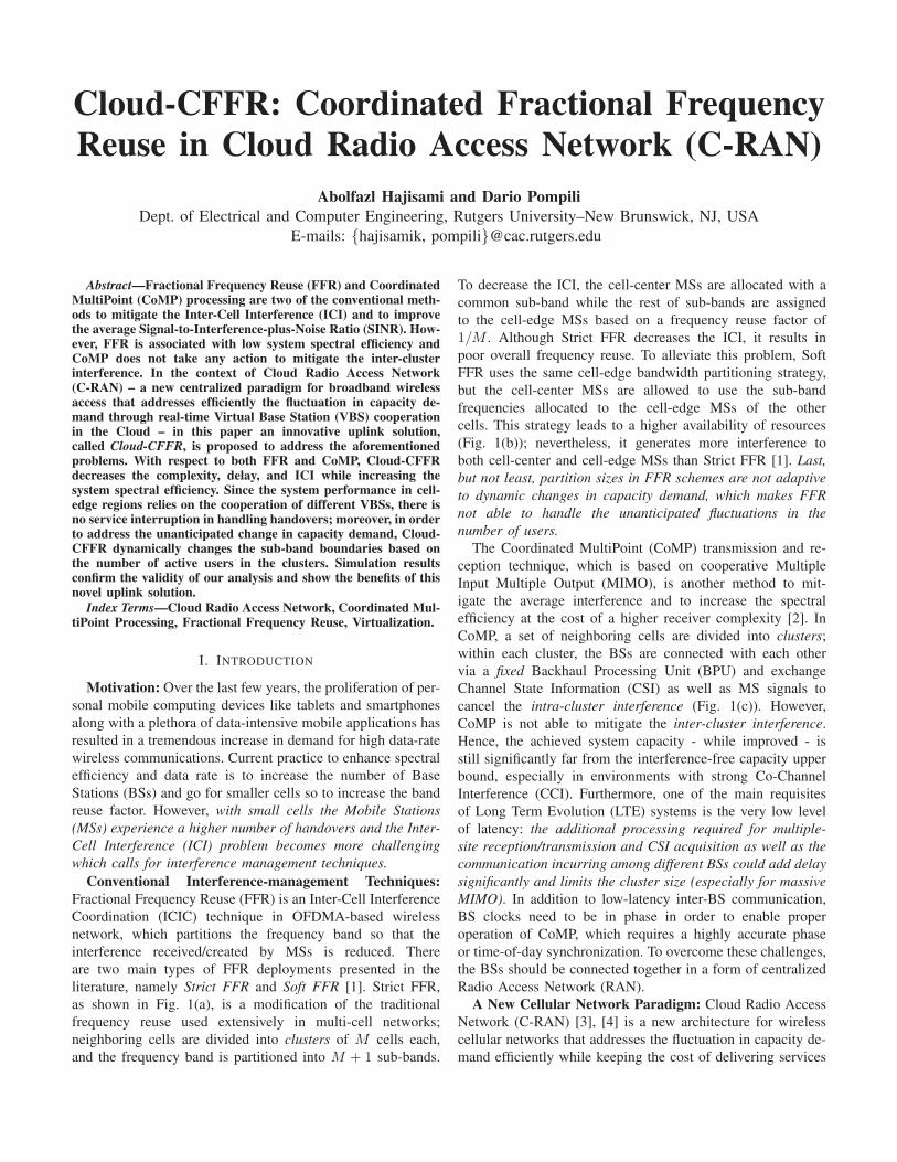
literature, namely Strict FFR and Soft FFR [1]. Strict FFR,
as shown in Fig. 1(a), is a modification of the traditional
frequency reuse used extensively in multi-cell networks;
neighboring cells are divided into clusters of M cells each,
and the frequency band is partitioned into M + 1 sub-bands.
To decrease the ICI, the cell-center MSs are allocated with a
common sub-band while the rest of sub-bands are assigned
to the cell-edge MSs based on a frequency reuse factor of
1/M . Although Strict FFR decreases the ICI, it results in
poor overall frequency reuse. To alleviate this problem, Soft
FFR uses the same cell-edge bandwidth partitioning strategy,
but the cell-center MSs are allowed to use the sub-band
frequencies allocated to the cell-edge MSs of the other
cells. This strategy leads to a higher availability of resources
(Fig. 1(b)); nevertheless, it generates more interference to
both cell-center and cell-edge MSs than Strict FFR [1]. Last,
but not least, partition sizes in FFR schemes are not adaptive
to dynamic changes in capacity demand, which makes FFR
not able to handle the unanticipated fluctuations in the
number of users.
The Coordinated MultiPoint (CoMP) transmission and re-
ception technique, which is based on cooperative Multiple
Input Multiple Output (MIMO), is another method to mit-
igate the average interference and to increase the spectral
efficiency at the cost of a higher receiver complexity [2]. In
CoMP, a set of neighboring cells are divided into clusters;
within each cluster, the BSs are connected with each other
via a fixed Backhaul Processing Unit (BPU) and exchange
Channel State Information (CSI) as well as MS signals to
cancel the intra-cluster interference (Fig. 1(c)). However,
CoMP is not able to mitigate the inter-cluster interference.
Hence, the achieved system capacity - while improved - is
still significantly far from the interference-free capacity upper
bound, especially in environments with strong Co-Channel
Interference (CCI). Furthermore, one of the main requisites
of Long Term Evolution (LTE) systems is the very low level
of latency: the additional processing required for multiple-
site reception/transmission and CSI acquisition as well as the
communication incurring among different BSs could add delay
significantly and limits the cluster size (especially for massive
MIMO). In addition to low-latency inter-BS communication,
BS clocks need to be in phase in order to enable proper
operation of CoMP, which requires a highly accurate phase
or time-of-day synchronization. To overcome these challenges,
the BSs should be connected together in a form of centralized
Radio Access Network (RAN).
A New Cellular Network Paradigm: Cloud Radio Access
Network (C-RAN) [3], [4] is a new architecture for wireless
cellular networks that addresses the fluctuation in capacity de-
mand efficiently while keeping the cost of delivering services

(a) (b) (c)
Fig. 1. (a) Strict-FFR and (b) Soft-FFR deployments with cell-edge reuse factor of 1/3; (c) Intra-cluster and inter-cluster interference in the uplink (wename the MS (BS) inside the cluster as internal MS (BS) and outside the cluster as external MS (BS)). In Coordinated MultiPoint (CoMP) processing BSscooperate with each other and exchange data through Backhaul Processing Unit (BPU) in order to cancel the intra-cluster interference.
to the users low. It also provides a higher degree of cooperation
and communication among BSs. C-RAN represents a clean-
slate design and allows for dynamic reconfiguration of com-
puting and spectrum resources. Characteristics of C-RAN are:
i) centralized management of computing resources, ii) collab-
orative communications, and iii) real-time cloud computing on
generic platforms. As shown in Fig. 2(a), C-RAN is composed
of Remote Radio Heads (RRHs) distributed over a wide
geographic region controlled by remote Virtual Base Stations
(VBSs) housed in a centralized processing pools. VBSs and
their corresponding RRHs are connected by high-bandwidth
low-latency media (e.g., the use of optical fibers allows for
a maximum distance of separation of 40 km between the
RRH and its VBS) [3]. The communication functionalities
of the VBSs are implemented on Virtual Machines (VMs)
hosted over general-purpose computing platforms, which are
housed in one or more racks of a small cloud datacenter. In a
centralized VBS pool, since all the information from the BSs
is resident in a common place, the BSs can exchange control
data at Gbps. This can provide higher degree of freedom in
order to make optimized and real-time decision so to improve
the overall system performance.
Centralized management of computing resources, i.e., BS
pooling, renders BS information global and, hence, enables
cooperative communication techniques at the MAC and PHY
layers that were previously not implementable due to strict
inter-BS coordination requirements (in terms of throughput
and latency). Although some recent works have studied the
cooperative communication techniques that can benefit from
C-RAN [5]–[7], research on enabling technologies for C-RAN
itself is still at a nascent stage and, hence, there are only a
few works in this area. The authors in [8] refer to C-RAN as
Software Defined Radio (SDR) cloud and suggest hierarchical
resource management where computing clusters are defined
and assigned to different radio operators, cells, or services.
In [9], the authors describe the virtual BS-pool structure and
discuss key system challenges in implementing this concept.
They also propose a hybrid processing to match the workload
of BS stack components. In [10], a partitioning and scheduling
framework is proposed that is able to reduce the compute
resources by 19%. In [11], the authors present a solution for
small cells that reconfigures the fronthaul based on network
feedback so to maximize the amount of traffic demand. In [12],
a cooperative PHY/MAC solution is presented to address the
inter-cell interference. In [13], the authors consider the C-
RAN with finite-capacity backhaul links, and propose a hybrid
compression strategy for downlink transmission to optimize
the backhaul capacity utilization.
In summary, prior work on C-RANs focused on the overall
system architecture, on the feasibility of virtual software BS
stacks as well as on the performance gains. In contrast to
existing works, we propose a novel cloud-based uplink solu-
tion supporting coordinated FFR that aims at improving the
Signal-to-Interference-plus-Noise Ratio (SINR) and, hence,
the overall system spectral efficiency, by fully exploiting the
centralized advantages offered by C-RAN.
Our Contribution: In this paper, we leverage the ad-
vantages of FFR, CoMP, and CRAN and propose a novel
uplink interference-cancellation solution to increase the system
spectral efficiency while also decreasing both the intra- and
inter-cluster interference. We first introduce the idea of “VBS-
Cluster,” in which we merge VBSs serving a cluster into a
unit VBS-Cluster while the RRHs’ antennae in each cluster
act as a single coherent antenna array distributed over a cluster
region. In the proposed solution, for each cell we define an
Interference Region (IR); based on the IR of its neighboring
cells, we then determine the Cell-Center Region (CCR). Since
the cell-center MSs experience high level of SINR, we propose
to apply CoMP processing only to cell-edge MSs, which leads
to a decrease in the total complexity and latency. Moreover,
in order to deal with inter-cluster interference, which is not
addressed in traditional CoMP, we propose to exploit the
cooperation of different VBSs for different cell-edge regions.
We define the clusters of size 2 and 3 depending on the IR

(a) (b) (c)
Fig. 2. (a) Cloud Radio Access Network (C-RAN) architecture, where the Base Stations (BSs) are physically unbundled into Virtual Base Stations (VBSs)and Remote Radio Heads (RRHs). VBSs are housed in centralized processing pools and can communicate with each other at Gbps speeds; (b) VirtualBase Station Cluster (VBS-Cluster); (c) The Interference Region (IR) associated with cell #3 (gray region) includes the cell itself as well as the neighboringCell-Edge Regions (CERs).
intersection of neighboring cells; we partition the frequency
band into 13 non-overlapping sub-bands, and allocate the
frequency bands to the MSs based on the their position. In
our solution, we also dynamically change the boundaries of
sub-bands and optimize their widths in order to address the
unanticipated fluctuations in the number of users and per-user
capacity demands. This way, unlike the traditional OFDMA
systems, the performance of the system in all the cell-edge
regions relies on the cooperation of different VBSs, which
avoids handover interruptions.
Paper Outline: In Sect. II, we present the system model
and detail the issues with CoMP and FFR. In Sect. III, we
introduce our solution, discuss its advantages, and explain
how it decreases the average interference while increasing
the system spectral efficiency with respect to (w.r.t.) current
solutions. In Sect. IV, we validate our assumptions through
simulations and show the benefits of our solution. Finally, in
Sect. V, we draw the main conclusions and wrap up the paper
by discussing future work.
II. SYSTEM MODEL
To understand better our proposed solution, we detail the
issues with FFR and CoMP, and explain why these methods
cannot overcome today’s cellular network challenges.
FFR has been proposed as a solution to find a tradeoff
between interference reduction and system spectral efficiency.
In Strict FFR, the overall system frequency band is partitioned
in such a way that, in a cluster of M cells, the MSs in the CCR
are allocated a common sub-band of frequencies while the rest
of the frequencies are equally partitioned into M sub-bands
and assigned separately to Cell-Edge Regions (CERs) of the
cluster. Figure 1(a) shows a cellular network using a Strict-
FFR deployment where the cell-edge reuse factor is equal to
1/3. Since the cell-edge MSs use different frequency sub-
bands than the cell-center MSs, the interference is reduced
in both CCR and CER. With Ktot defining the total number
of available subcarriers, the number of subcarriers allocated
to the cell-center MSs Kcenter and cell-edge MSs Kedge is
given in [1] as,
Kcenter =⌈
Ktot
(rcenter
r
)2⌉
,
Kedge = ⌊(Ktot −Kcenter) /M⌋ ,(1)
where rcenter and r are the CCR and cell radii, respectively.
Although Strict FFR increases the SINR, only two sub-
bands are allocated per cell in a cluster, which still leads
to poor system spectral efficiency. In order to alleviate this
problem, Soft FFR has been proposed. As shown in Fig. 1(b),
in Soft FFR the frequency partitioning is the same as in
its Strict counterpart, but the cell-center MSs are allowed to
share sub-bands of CERs in the other cells. In Soft FFR, the
allocation of subcarriers for cell-center MSs is the same as in
Strict FFR, whereas the number of subcarriers allocated to the
cell-edge MSs are given respectively as [1],
Kedge = min (⌈Ktot/M⌉ ,Ktot −Kcenter) , (2)
And yet, while Soft FFR increases the system spectral effi-
ciency, it results in more interference to both cell-edge and
cell-center MSs, leading to a high service outage probability.
Moreover, in both Strict FFR and Soft FFR, the partition sizes
are fixed and cannot adapt dynamically to the demand changes
per region. This means that, as there is no coordination among
the neighboring cells, changing the partition sizes in one cell
may cause intensive interference in the other cells.
To solve the aforementioned problems and improve the
system performance, we propose to use both CoMP and FFR
under the C-RAN architecture. In CoMP, a set of neighboring
cells is divided into clusters, and in each cluster the BSs
coordinate with each other in order to improve the average
SINR. Since in each cluster the BSs receive a combination of
internal- and external-MS signals (Fig. 1(c)), the goal of CoMP
is to cancel the intra-cluster interference (caused by internal

MSs from neighboring cells). We assume that there are Msingle-antenna BSs and N single-antenna MSs (N ≤ M ) in
the cluster. Under these assumptions, the relationship between
the received signals by internal BSs and the transmitted MS
signals at different time instants can be expressed through
the following linear noisy model (where, for clarity, the time
variable t is omitted),
y(k) =N∑
j=1
sinj (k)hinj (k) + n(k) = Hin(k)sin(k) + n(k),
(3)
where sin(k) = [sin1 (k), . . . , sinN (k)]T is the N × 1 vector
of internal MS signals over the kth subcarrier, y(k) =[y1(k), . . . , yM (k)]T is the M × 1 vector of signals received
by the internal BSs, Hin(k) is the M ×N channel coefficient
matrix between the MSs and BSs (hinj (k) being its jth
column), and n(k) = [n1(k), . . . , nM (k)]T is the M × 1background noise vector with independent components. It
should be mentioned that in (3) we have included the inter-
cluster interference as a part of the background noise, i.e.,
n(k) = Hex(k)sex(k) +w(k), (4)
where sex(k) = [sex1 (k), . . . , sexL (k)]T is the L × 1 vector
of the external-MS signals (causing inter-cluster interference),
Hex(k) is the M×L channel coefficients between the external
MSs and internal BSs (hexi,j(k) being its (i, j)th component),
and w(k) = [w1(k), . . . , wM (k)]T is the M × 1 vector of
Additive White Gaussian Noise (AWGN).
A simple form of coordination is achieved by implementing
a Zero-Forcing (ZF) receiver [6]. In a ZF receiver (for the
uplink), since the CSI from all the BSs in a cluster is available,
we can form the equalizer as GZF =(
H†inHin
)−1
H†in,
where the output of the ZF receiver is given by,
sin(k) = GZF (k)y(k) = sin(k) +GZF (k)n(k), (5)
where sin(k) = [sin1 (k), . . . , sinN (k)]T is the N × 1 vector of
estimated internal-MS signals, each of which is associated with
a combination of the background noises at all the receivers.
From (4) and (5), it is clear that CoMP is able to cancel
the intra-cluster interference, but does not take any action to
decrease the inter-cluster interference (which is incorporated
in the background noise),
sin(k) = sin(k) +GZF (k)Hex(k)sex(k)︸ ︷︷ ︸
Inter−Cluster Interfernce
+GZF (k)w(k)︸ ︷︷ ︸
AWGN
.
(6)
If we assume that the background noise at the lth receiver has
a variance of σ2l , then the noise in the ith estimated MS signal
has a variance of g2i1σ21+· · ·+g2iMσ2
M , where gij is the (i, j)th
component of the equalizer matrix GZF . It is clear from (6)
that the interference generated by the external cluster-edge
MSs dramatically decreases the SINR (due to the high absolute
value of channel coefficient∣∣hexi,j(k)
∣∣ between external cluster-
edge MS and internal BSs) and has a severe destructive impact
on the performance of the serving cluster.
III. PROPOSED SOLUTION
The intensity of inter-cluster interference is determined by
the network topology, which depends on the MS distribution,
the inter-site distance, and the distances between external MSs
and internal BSs. In traditional CoMP, since only a group of
BSs are connected to each other and can exchange data, the
cluster boundaries are set and cannot be changed dynamically
as needed. Consequently, we cannot do any high data rate
exchange among the clusters (as required to enable cooperative
interference cancelation), and messages between clusters need
to travel over expensive backhaul links. Hence, CoMP only
changes the boundaries of interference from cell to cluster.
On the other hand, increasing the cluster size would lead to
an increase in complexity to run the CoMP algorithms and
also to an increase in the delay to exchange the CSI between
MSs and BSs, which conflicts with the low-latency requirement
of LTE systems. In addition, certain MSs (especially in CCR
and close to BS) may only experience small interferers, which
makes the CoMP with reasonable computational complexity
largely ineffective.
Conversely, in C-RAN, all the VBSs of a large region are
centralized in a common virtualized datacenter. This central-
ized characteristic along with real-time virtualization technol-
ogy provides extra degree of freedom that is useful to mitigate
both the intra-cluster interference as well as the inter-cluster
interference. In addition, all the VBSs can communicate and
exchange data with each other at Gbps speeds. Unlike in
traditional cellular systems where each cell is only associated
statically with a certain cluster, in C-RAN we are able to
associate each cell with different clusters. We leverage these
properties to form virtual clusters so to mitigate the intra-
and inter-cluster interferences, to decrease the complexity of
the system, and at the same time to boost the system spectral
efficiency.
Virtual Base Station Cluster: Clustering the neighboring
cells in a C-RAN architecture – together with enabling the
coordination of the VBSs in the cluster – can improve the
system performance by exploiting the extra degrees of freedom
to make optimal decisions. Here, we introduce the idea of VBS-
Cluster, wherein the VBSs associated with a certain cluster
are merged together and the RRHs’ antennae in each cluster
act as a single coherent antenna array distributed over the
cluster region. Figure 2(b) shows two exapmle VBS-Clusters,
#1 (shaded in red, on the left) and #2 (dark shaded, on the
right), where the sizes of the clusters are 2 and 3, respectively.
Coordinated FFR in the Cloud (Cloud-CFFR): In our
Cloud-CFFR solution, we introduce a new clustering approach
by exploiting the advantages of both FFR and CoMP as
well as the capabilities of C-RAN to improve the overall
system performance along different performance dimensions.
Although the idea of Cloud-CFFR can be applied to any
cell deployment, for simplicity we use regular hexagonal grid
deployment (Fig. 2(c)). We define an Interference Region (IR)
for each cell as a region in which if MSs from other cells
moved in, they could produce an “intense” interference at the

BS serving the cell. Figure 2(c) shows three neighboring cells
and the IR associated with cell #3 (in gray), which includes
the cell itself as well as its neighboring Cell-Edge Regions
(CERs). Here, both MS #1 and #2 are cell-edge MSs; in a
system with a frequency reuse factor equal to 1, they may have
destructive effects on the performance of their neighboring
cells. Hence, their interference on the other cells needs to be
canceled or mitigated to improve the overall SINR. Although
MS #2 is a cell-edge MS, its interference at RRH #3 is low.
This is because MS #2 is far from RRH #3 and, due to the path
loss, the power of received signal (from MS #2) in the uplink
at RRH #3 is low; hence, there is no need for VBS #2 and #3
to cooperate with each other in order to cancel the interference
caused by MS #2 at RRH #3. Conversely, since MS #1 is in
the IR of cell #3, there may be an intense interference from
MS #1 to RRH #3; thus, coordination between VBS #1 and
#3 is needed to cancel this interference.
In our solution, like in the traditional FFR, we partition the
frequency band into 2 sub-bands, namely Fc and Fe, for cell-
center and cell-edge regions, respectively. Then, as shown in
Fig. 3(a), we further divide the cell-edge spectrum (Fe) into 12portions, each allocated to a certain cluster of VBSs to serve
a certain region of cell edge. So, in each cell all the frequency
band is used by the MSs and the frequency reuse factor of 1is achieved.
Unlike in the traditional CoMP – in which the positions
of MSs in the cell are not taken into account and all the
BSs within a cluster cooperate with each other by exchanging
CSI and MS signals – in our solution we divide the VBSs
into virtual edge clusters based on the MS positions and
minimize the number of coordinated VBSs so to bound the
overall complexity and the delay associated with multiple-
site reception/transmission as well as with CSI acquisition. In
fact, we distinguish among the MSs based on their positions.
We also leverage the C-RAN architecture and virtualization
technology in such a way as to associate each VBS with
different virtual edge clusters; this means that, for different
areas of CER, each VBS coordinates with different VBSs in
different virtual clusters, which increases the overall system
performance. This way, only VBSs which have intensive
interference from each other cooperate with each other to
cancel the ICI. Figure 3(a) shows the intersections of IRs of
7 hexagonal neighboring cells. We define CCR as the area
where there is no intersection between the IR of the serving
cell and the IRs of its neighboring cells (central and pink in
the figure). If we define the IR of the ith cell as IR(i) then
its CCR is defined as relative complement of union of the IRs
of its neighbouring cells with respect to IR(i),
CCR(i) = IR(i)\ ⋃
j∈N (i)
IR(j), (7)
where N (i) is the set of neighbouring cells in the first tier of
the ith cell.
Since the CCR of each cell is out of the IRs of its neighbor-
ing cells, the interference from this region to the neighboring
RRHs is not intense; hence, applying CoMP in this region
would be highly inefficient due to the complexity, delay, and
bandwidth usage to compute and exchange the CSI. Conse-
quently, in our solution we do not apply computationally-
expensive CoMP in CCR and the system performance in this
region relies on simple single transmitter and receiver. To
allocate the subcarriers to the CCR, we follow the strategy
expressed in (1), as the number of allocated subcarriers is
proportional to the CCR,
KCCR =⌈
Ktot
(ACCR
Acell
)⌉
, (8)
where Ktot is the total number of subcarriers, ACCR is the
area of CCR, and Acell is the area of the cell site.
The system operation in cell-edge regions relies on the
cooperation of different VBSs for different regions. Since we
operate under the C-RAN architecture and all the VBSs are
co-located in a common place (at the server, enclosure, or rack
level in a datacenter), it is possible for each VBS to cooperate
with all its neighboring VBSs and share the CSI as well as MS
signals at Gbps. We define the CER of the ith cell as relative
complement of CCR(i) with respect to IR(i),
CER(i) = IR(i)\CCR(i), (9)
where, as shown in Fig. 3(a), CER(i) consists of different
intersection regions each of which is the intersection of IR(i)with the IR of different neighbouring cells. We propose to
divide the VBSs into clusters based on the intersections of
their corresponding IRs in CER and apply CoMP within each
cluster so to cancel the intra-cluster interference. This means
that, in the cell edge and in each intersection region, the
system performs under the cooperation of associated VBSs.
For example, in the IR intersection of cells #1, #2, and #3,
distinguished by bold lines on the right side of Fig. 3(a), the
system performs under the cooperation of VBSs #1, #2, and
#3. This is because MSs located in this (dark blue) region and
served by each of these three VBSs #1, #2, and #3 induce
an intense interference on the other two VBSs (non-serving
VBSs). For instance, in Fig. 3(a), MS #1 (which is served by
VBS #1) is inside the IR of cells #2 and #3 and may cause
poor system performance to VBSs #2 and #3; however, since
MS #1 is outside the IR of the other neighboring cells and
is far from their corresponding RRHs, due to the path loss, it
does not induce a large interference on their VBSs.
To generalize from this example, we can state that in order
to improve the SINR of received signal by each RRH, we
need to cancel the interference from those MSs located in
its corresponding IR. This requires cooperation of each VBS
with all its neighboring VBSs and in different clusters, which
is only achievable in C-RAN architecture. Similarly, with
reference to the aforementioned example for MS #1, in the
IR intersection of cells #1 and #6, the gray area distinguished
by bold line on the left side of Fig. 3(a), only VBSs #1 and
#6 need to collaborate with each other. In this way, each
VBS is simultaneously associated with 12 different clusters
to serve different regions of cell edge. Similar to (8) where
the allocated subcarriers to CCR is proportional to the area of

(a) (b) (c)
Fig. 3. (a) Intersections of serving cell’s Interference Region (IR) with its neighboring cells’ IRs; the MSs located in Cell-Center Region (CCR) have a lowlevel of interference while the MSs located in Cell-Edge Region (CER) (e.g., MS #1) have an intensive interference on its neighbouring cells that needs to becancelled; (b) The average distance between the MSs using the same subcarrier and located in the different clusters are 3 times of cell radius. The frequency
reuse factor is equal to 1 and all the frequency band is used in each cell; (c) Equally sized hexagonal cell structures where r is the cell radius, D =√
3r is
the inter-site distance, Ri is the IR radius, and A = 3√
3
2r2 is the cell area.
CCR, the number of allocated subcarriers to each edge-cluster
region is given by,
KCER(p) =⌊
Ktot
(ACER(p)M(p)Acell
)⌋
, (10)
where KCER(p) is the number of allocated subcarriers to the
pth cluster (1 < p < 12), ACER(p) is the area of the edge-
cluster region, and M(p) is the cluster size.
As in our solution we only apply CoMP to CERs and
the average cluster size is 2.5, the complexity and delay is
reduced compared to traditional CoMP. Moreover, as depicted
in Fig. 3(b), in our solution the MSs using the same frequency
sub-bands and served by different clusters are so far from
each other that each cluster induces a very low level of
interference on the corresponding neighboring cluster. The
average distance between the MSs using the same subcarrier
and located in the different clusters are 3 times of cell
radius, which is almost equal to the reuse distance of a
cellular system with frequency-reuse factor of 1/3. Since in our
solution CoMP cancels the intense intra-cluster interference
and VBSs experience a small inter-cluster interference (due
to the long average inter-cluster distance), we achieve a low
level of interference on the received uplink signal. The SINR
of received signals at ith RRH can be expressed as,
SINRiCloud−CFFR =
βiPi|hini,i|2
σ2+∑
j∈C,j 6=i
Pj|hini,j|2+∑
l∈I
Pl|hexi,l|2
+(1−βi)Pi|gzf
ihin
i |2σ2+
∑
l∈I
Pl|gzfi
(k)hexl
(k)|2(11)
where Pi is the transmitted power of the MS located in the
ith cell, C is the set of cells in the serving cluster, and Iis the set of interfering external cells. hini,j and hexi,j are the
(i, j)th components of Hin and Hex, respectively. gzfi is the
ith row of the equalizer matrix GZF , hini and hex
i are the ith
column of Hin and Hex, respectively, and σ2 is the power of
the noise. βi is the location indicator and is equal to 1 when
the MS is located in the CCR of ith cell and equal to 0 when
the MS is located in the CER. We will analyse the SINR and
compare it with different methods in Sect. IV.
Dynamic Frequency Sub-band: In Cloud-CFFR, we are
also able to change dynamically the dedicated sub-band to
each region. This leads to higher capacity and multiplexing
gains without deploying additional antennae at the RRHs. In
traditional FFR systems, due to the static spectrum resources,
we are not able to handle unanticipated fluctuations in the
number of users and per-user capacity demands. However, in
some scenarios like natural or man-made disasters or due to
the temporal/geographical fluctuations of MSs (the so-called
tidal effect), the network may have more service demanding
users in some regions. To address this problem, we propose
to optimize the dedicated frequency sub-band to each cluster
based on the number of active MSs in the clusters. Whenever
in a certain cluster we have an overload and need to serve more
MSs, the associated VBSs communicate with each other and
dynamically change the sub-band boundaries so to increase the
frequency sub-band for the overloaded region. If the associated
VBSs have extra room in the other clusters and regions, they
negotiate with each other and decrease the dedicated frequency
sub-band of the other regions and increase the frequency sub-
band of the overloaded region.
In the case of extra demand in the CCR of the jth cell,
we allocate the unused subcarriers of edge-clusters to CCR.
Let Pj (p, k) be the subset of VBSs (including the jth VBS)
serving the pth edge-cluster over the kth subcarrier (1 < k <KCER(p)) in CER of the jth cell and Pj (p, k) = Pj (p, k) \j.To avoid the excessive ICI caused by allocating the kth
subcarrier of CER to CCR, VBSs in Pj (p, k) are not allowed
to use the kth subcarrier. Conversely, in the case of extra

demand in some edge-cluster in the CER of the jth cell, we
allocate the unused subcarriers of CCR and the other edge-
clusters to the overloaded edge-cluster. Let Pj (p) be the subset
of VBSs serving the pth edge-cluster of jth cell. Then, to
avoid the excessive ICI caused by allocating the kth subcarrier
of the qth edge-cluster to the overloaded edge-cluster (say
the ith), the VBSs in Pj (q, k) \Pj (i) are not allowed to
use the kth subcarrier. However, in the case of allocating
unused subcarriers of CCR to overloaded edge-clusters, there
is no excessive ICI to the performance of Pj (q) and all the
associated VBSs with the overloaded edge-cluster can use the
subcarriers from associated CCRs.
Handover Scheme: In the Fourth Generation (4G) wireless
networks, only Hard Hand-Over (HHO) (in which the con-
nection between the serving BS and MS is terminated before
the connection between the new BS and the MS is started)
is defined to support MSs’ mobility. As studied in [14], the
service disruption time caused by HHO can be 250 ms or
more, which is intolerable for some real-time services like
Voice over IP (VoIP). On the other hand, with small cells, MSs
perform handover more frequently leading to a decrease in the
perceived Quality of Service (QoS). The degradation of QoS is
a consequence of short interruption in communication during
HHO due to redundant overhead generated for controlling
and managing handovers. In our solution, cell-edge MSs are
actively connected to 2 or 3 VBSs simultaneously so they do
not have to terminate their connection with a serving VBS
when they are moving from one cell to the neighboring cells.
Hence, even with small cells and in a high-mobility scenario,
MSs do not experience any service disruption as each MS
operates under cooperation of multiple VBSs within a cluster.
IV. PERFORMANCE EVALUATION
In this section, we analyze the behaviour of our proposed
Cloud-CFFR solution in different regions and provide a range
of simulations to evaluate its performance.
Setting: Table I lists the parameters used during our experi-
ments. In the simulations, we use the equally-sized hexagonal
cell structure with an inter-site distance D and cell radius r(Fig. 3(c)). MSs are uniformly distributed over the cell site
and d is the distance between the MS and its serving RRH.
To implement conventional CoMP, we consider a cluster with
size 3. To compare Cloud-CFFR with Strict FFR and Soft
FFR, we consider the structures showed in Figs. 1(a) and (b)
with cell-edge reuse factor of 1/3 and CCR radius equal to
0.7r (which is the optimum CCR radius for M = 3 [15]).
Also, to have the same CCR for Cloud-CFFR, we consider
Ri = 1.3r, as illustrated in Fig. 3(c). In the simulations, we
compare performance metrics among the traditional cellular
network (without Inter-Cell Interference Coordination (ICIC)),
CoMP, Strict FFR, Soft FFR, and Cloud-CFFR.
Propagation Model and Discussion: We concentrate on the
effects of path loss and shadowing, and employ a commonly-
used signal-propagation model as follows,
Prx = K ·(
dd0
)−λ
· ψ · Ptx, (12)
where Prx, Ptx, d, and λ denote received and transmitted
power, propagation distance, and path loss exponent, respec-
tively; the parameter d0 indicates a reference distance where
the received signal strength is known. The random variable ψis used to model the slow fading caused by shadowing and fol-
lows a log-normal distribution such that the variable 10 log10 ψfollows a zero mean Gaussian distribution. Finally, parameter
K is a constant which corresponds to the path loss at distance
d0 and depends on carrier frequency, antenna characteristics,
and propagation environment. With this definition the channel
between a MS and a RRH is h =√Kψ
(dd0
)−λ/2
. Hence,
based on the system model and proposed solution presented in
Sect. III, the SINR of received signals at ith RRH for different
methods can be expressed as,
SINRiStrictFFR =
βiPi|hini,i|2
σ2+∑
j∈C,j 6=i
Pj|hini,j|2+∑
l∈I
Pl|hexi,l|2
+(1−βi)Pi|hin
i,i|2σ2+
∑
l∈I
Pl|hexi,l|2
,
SINRiSoftFFR =
Pi|hini,i|2
σ2+∑
j∈C,j 6=i
Pj|hini,j|2+∑
l∈I
Pl|hexi,l|2
,
SINRiCoMP =
Pi|gzfi
hini |2
σ2+∑
l∈I
Pl|gzfi
(k)hexl
(k)|2 ,
(13)
According to (13) and (11), here, we explain how Cloud-
CFFR increases the overall throughput with respect to the
other methods.
TABLE ISIMULATION PARAMETERS.
Parameters Mode/Value
Cellular Layout Hexagonal grid, 19-cell sites
Channel Model Path Loss and Shadowing
Cell Radius 500 mChannel Bandwidth (∆B) 10 MHz
Number of Occupied Subcarriers 600Subcarrier Spacing 15 kHz
CCR Radius for Soft FFR and Strict FFR 0.7rIR Radius 1.3r
Distance-dependent Path Loss 38.88 + 32log(d) dBPath Loss Exponent 3.2Carrier Frequency 2.1 GHz
Number of Antennae (NTX , NRX) (1, 1)MS Antenna Omni-directional
Channel State Information Ideal
Receiver Processing for CoMP Zero Forcing (ZF)
Modulation Scheme OFDMA
Compared to the Soft FFR, since∣∣hini,j
∣∣ in Cloud-CFFR
is smaller (due to the higher path loss) than the one in
Soft FFR we expect to have a better SINR for cell-center
MS (βi = 1). For cell-edge MS (βi = 0), since there is
no intra-cluster interference in Cloud-CFFR, we also expect
to have a better performance than Soft FFR. Compared to
the Strict FFR, the performance is the same for cell-center
MS, but SINR for cell-edge MSs in Cloud-CFFR is less
than the one in Strict FFR. This is because the number of
interfering external cells in Strict FFR is less than Cloud-
CFFR (|IStrictFFR| < |ICloud−FFR|). However, the number

0.1 0.2 0.3 0.4 0.5 0.6 0.7 0.8 0.9 1−5
0
5
10
15
20
25
30
35
Normalized Distance (d/r)
SIN
R (
dB
)
Without ICIC
Soft FFR
CoMP
Strict FFR
Cloud−CFFR
2 2.5 3 3.5 4 4.55
10
15
20
25
30
35
40
Path Loss Exponent
Avera
ge T
hro
ughput
(Mbps)
Without ICIC
Soft FFR
CoMP
Strict FFR
Cloud CFFR
4 6 8 10 12 14 160
0.1
0.2
0.3
0.4
0.5
0.6
0.7
0.8
0.9
1
Threshold (dB)
Outa
ge P
robabili
ty
Without ICIC
Soft FFR
CoMP
Strict FFR
Cloud−CFFR
(a) (b) (c)
Fig. 4. (a) Signal-to-Interference-plus-Noise Ratio (SINR) for different Normalized Distances d/r; (b) Average Throughput per subcarrier for different PassLoss Exponent λ; (c) Outage probability for different thresholds in dB.
of available subcarriers per cell in Cloud-CFFR is 1.5 times
more than the one in Strict FFR so that we expect to have more
overall throughput with Cloud-CFFR (we will discuss about
it through the simulations). Also, compared to CoMP, since
the distance between the external MSs and internal RRHs is
increased, the corresponding channel matrix in Cloud-CFFR
has a smaller norm (∥∥HCloud−CFFR
ex
∥∥2
2<
∥∥HCoMP
ex
∥∥2
2) which
results to have a better performance in terms of both SINR
and throughput. Moreover, the complexity of Cloud-CFFR is
much lower than CoMP. The complexity of CoMP algorithm
depends on the numbers of cooperative RRHs (M ), associated
MSs (N ), and subcarriers (kc). For instance, ZF receiver has
a computational complexity of O(kcM
3N3)
[16]. Since in
CoMP the interference cancelation is applied to all the sub-
carriers (kc = Ktot), the system has an overall computational
complexity of O(KtotM
3N3). However, in Cloud-CFFR the
average cluster size is 2.5 (M = N = 2.5) and ZF only is ap-
plied to the CER so that kc = 0.5Ktot which leads to have less
computational complexity (OCloud−CFFR = 0.22OCoMP).
Simulation Results: To test and validate the aforemen-
tioned statements, in the first simulation, we compare the
SINR in terms of Normalized Distance. As it is shown in
Fig. 4(a), Cloud-CFFR outperforms both CoMP and Soft FFR
in CER; however, Strict FFR has a greater SINR in CER. This
is because Strict FFR uses a frequency reuse factor of 1/3 in
CER and, according to (1) (for rcenter = 0.7r), only use 66%of the frequency band. However, as we show next, the overall
throughput of Strict FFR is less than that of Cloud-CFFR.
Since the interference highly depends on path loss exponent,
we also explore the variation of the average throughput of each
subcarrier versus path loss exponent for different schemes. The
throughput of each cell is given by,
R =k0Ktot
∆B log2 (1 + SINR) , (14)
where k0 and Ktot are the numbers of available subcarriers
per cell and of total subcarriers, respectively, and ∆B is the
channel bandwidth. As shown in Fig. 4(b), for an urban area
where the average path loss exponent is 3.5, Cloud-CFFR
has an average throughput of 25.83 Mbps, whereas for Strict
FFR, Soft FFR, and CoMP the average throughput is 17.77,
16.98, and 21.84, respectively. As it is clear from Fig. 4(b),
although Strict FFR has a better SINR in CER, its overall
throughput is less than that of Cloud-CFFR. This is because
Cloud-CFFR use all of the spectrum (k0 = Ktot), while Strict
FFR can only use a portion of it (k0 = 0.66Ktot). We also
examine the performance of our solution in terms of outage
probability, which is the probability that a MS’s instantaneous
SINR falls bellow a certain threshold θ, i.e., Pr (outage) =Pr (SINR < θ) = 1− Pr (SINR > θ). Figure 4(c) shows the
variation of the outage probability in terms of different SINR
thresholds.
In the other experiment we explore the performance of our
solution for different SNR values. As it is shown in Fig. 5(a),
Strict FFR does not have a good performance for low SNR
values, while our proposed solution outperforms the other
schemes for all the SNR values. For instance, for SNR=20 dB, Cloud-CFFR has an ASSE of 2.32 bps/Hz/cell, while
for regular CoMP, Soft FFR, and Strict FFR, the ASSE is
equal to 1.97, 1.54, and 1.62, respectively. We also compare
the Cumulative Distribution Function (CDF) concerning the
SINR for different schemes; it is clear from Fig. 5(b) that for
traditional network, Soft FFR, and CoMP, 20% of the MSs
experience a SINR less than 0 dB. This means that the power
of the received interference for 20% of MSs is greater than
the power of received desired signal. However, in our solution
all the MSs experience a SINR greater than 2.33 dB.
As discussed in Sect. III, to address the fluctuation in
capacity demand, we propose to change dynamically the
frequency sub-band boundaries. To examine this characteristic
of Cloud-CFFR, we simulated the following simple scenario;
let us assume that a set of cells have an equal number of MSs
(in our simulation the number of MSs per cell varies from 50to 200), each cell has 50 resource blocks to serve the MSs,
and in each cell an active MSs needs 1 resource block to be
served. We also assume that we have three types of cells: 1)
cells where the probability of cell-center and cell-edge MSs to
be active is 1/2 (i.e., density of active MSs in CER and CCR
is equal), 2) cells where the the probability of cell-center MSs
to be active is 1/4 while the probability of cell-edge MSs to be

0 5 10 15 20 250.4
0.6
0.8
1
1.2
1.4
1.6
1.8
2
2.2
2.4
SNR (dB)
AS
SE
(bps/H
z/c
ell)
Without ICIC
Soft FFR
CoMP
Strict FFR
Cloud−CFFR
−5 0 5 10 15 20 25 30 350.1
0.2
0.3
0.4
0.5
0.6
0.7
0.8
0.9
1
SINR (dB)
CD
F
Without ICIC
Soft FFR
CoMP
Strict FFR
Cloud−CFFR
50 100 150 2000
0.05
0.1
0.15
0.2
0.25
0.3
0.35
Number of MSs
Blo
ckin
g P
robabili
ty
Strict FFR
Soft FFR
Cloud−CFFR
(a) (b) (c)
Fig. 5. (a) Average Spectral Efficiency as a function of Signal-to-Noise Ratio (SNR); (b) Cumulative Distribution Function (CDF) as a function of Signal-to-Interference-plus-Noise Ratio (SINR); (c) Comparison of Blocking Probability for different number of MSs.
active is 3/4 (i.e., the density of active MSs in CER is greater
than CCR), and 3) cells where the the probability of cell-center
MSs to be active is 3/4 while the probability of cell-edge
MSs to be active is 1/4 (i.e., the density of active MSs in
CCR is greater than CER). Each cell can be any one of the
three aforementioned types with equal probability. Figure 5(c)
compares the blocking probability when the number of users
per cell increases; as it is shown, the blocking probability for
Cloud-CFFR is less than the traditional network and we are
able to serve more active MSs.
V. CONCLUSION AND FUTURE WORK
In the context of Cloud Radio Access Network (C-RAN) we
proposed and validated a novel solution, named Coordinated
Fractional Frequency Reuse in the Cloud (Cloud-CFFR). Our
innovative cellular-uplink solution mitigates the inter-cluster
interference, the complexity, and delay while increasing the
system spectral efficiency. We proposed to apply CoMP only
to cell-edge MSs and exploit the cooperation of different
VBSs for different cell-edge regions. Moreover, to address
the unanticipated change in capacity demand, Cloud-CFFR
dynamically changes the sub-band boundaries based on the
number of active users in the clusters. Simulation results
confirmed the validity of our analysis and show the benefits
of this novel uplink solution. For instance, in the urban area
Cloud-CFFR outperforms Strict FFR, Soft FFR, and CoMP in
the average throughput by 45%, 52%, and 20%, respectively.
Future Work: To validate the proposed ideas on a real-
time emulation, we are currently working on testbed imple-
mentation. The computer we use in the testbed is a Dell
workstation with a 6-core Intel Xeon E5-1650 processor with
12 threads and 32GB of RAM. We also use Ettus B210
boards as Universal Software Radio Peripherals (USRPs) to
establish communication between the BSs and the MSs. For
each VBS, we run OpenAirInterface, an open-source LTE
platform, on 64-bit Linux server and provision it with the
required computing resources.
Acknowledgment: This work was supported in part by the
National Science Foundation Grant No. CNS-1319945.
REFERENCES
[1] N. Saquib, E. Hossain, and D. I. Kim, “Fractional frequency reusefor interference management in lte-advanced hetnets,” IEEE Wireless
Communications, vol. 20, no. 2, pp. 113–122, 2013.[2] D. Lee, H. Seo, B. Clerckx, E. Hardouin, D. Mazzarese, S. Nagata,
and K. Sayana, “Coordinated multipoint transmission and reception inlte-advanced: deployment scenarios and operational challenges,” IEEE
Communications Magazine, vol. 50, no. 2, pp. 148–155, 2012.[3] D. Pompili, A. Hajisami, and H. Viswanathan, “Dynamic provisioning
and allocation in Cloud Radio Access Networks (C-RANs),” Ad Hoc
Networks, vol. 30, pp. 128–143, 2015.[4] C. M. R. Institute, “C-RAN: The Road Towards Green RAN,” in C-RAN
International Workshop, Oct. 2011.[5] A. Sang, X. Wang, M. Madihian, and R. D. Gitlin, “Coordinated load
balancing, handoff/cell-site selection, and scheduling in multi-cell packetdata systems,” Wireless Networks, vol. 14, no. 1, pp. 103–120, 2008.
[6] C. Wang, E. K. S. Au, R. D. Murch, W. H. Mow, R. S. Cheng, andV. Lau, “On the performance of the mimo zero-forcing receiver in thepresence of channel estimation error,” IEEE Transactions on Wireless
Communications, vol. 6, no. 3, pp. 805–810, 2007.[7] S. Gollakota, S. Perli, and D. Katabi, “Interference alignment and can-
cellation,” ACM SIGCOMM Computer Communication Review, vol. 39,no. 4, pp. 159–170, 2009.
[8] V. Marojevic, I. Gomez, P. Gilabert, G. Montoro, and A. Gelonch,“Resource management implications and strategies for sdr clouds,”Analog Integrated Circuits and Signal Processing, vol. 73, no. 2, pp.473–482, 2012.
[9] Z. Zhu, P. Gupta, Q. Wang, S. Kalyanaraman, Y. Lin, H. Franke, andS. Sarangi, “Virtual Base Station Pool: Towards a Wireless NetworkCloud for Radio Access Networks,” in ACM International Conference
on Computing Frontiers (CF), May 2011.[10] S. Bhaumik, S. P. Chandrabose, M. K. Jataprolu, G. Kumar, A. Muralid-
har, P. Polakos, V. Srinivasan, and T. Woo, “Cloudiq: a framework forprocessing base stations in a data center,” in International conference
on Mobile computing & networking. ACM, 2012, pp. 125–136.[11] K. Sundaresan, M. Y. Arslan, S. Singh, S. Rangarajan, and S. V.
Krishnamurthy, “Fluidnet: a flexible cloud-based radio access networkfor small cells,” in International conference on Mobile computing &
networking. ACM, 2013, pp. 99–110.[12] A. Hajisami, H. Viswanathan, and D. Pompili, “Cocktail Party
in the Cloud: Blind Source Separation for Co-operative CellularCommunication in Cloud RAN,” Proc. of the IEEE Intl. Conf. on Mobile
Ad hoc and Sensor Systems (MASS), pp. 37–45, 2014.[13] P. Patil and W. Yu, “Hybrid compression and message-sharing strategy
for the downlink cloud radio-access network,” Proc. of the IEEE
Information Theory and Applications Workshop (ITA), pp. 1–6, 2014.[14] W. Jiao, P. Jiang, and Y. Ma, “Fast handover scheme for real-time
applications in mobile wimax,” in IEEE International Conference on
Communications (ICC), 2007, pp. 6038–6042.[15] M. Assaad, “Optimal fractional frequency reuse (ffr) in multicellular
ofdma system,” IEEE Vehicular Technology Conference, pp. 1–5, 2008.[16] F. R. P. Cavalcanti, Resource Allocation and MIMO for 4G and Beyond.
Springer, 2014.