closed loop simulation model development process for
TRANSCRIPT
1 Defence Science and Technology Organisation
Closed Loop Simulation Model Development Process For Helicopter Air Operational Research
Gokhan Ibal1; Ziming Tu1; Hal Harvey2; Igor Siemienowicz3; Mario Selvestrel3; Tim Patterson4
1. Air Operations Division - DSTO [email protected]
2. Dstl UK secondee to Air Operations Division - DSTO
3. KESEM International [email protected]
4. Online Engineering [email protected]
Abstract. Air Operations Division (AOD) uses Operations Research (OR) to enhance the Australian Defence Force’s (ADF) use of aircraft, weapons, sensors and associated equipment through upgrades, new acquisitions and improved tactical deployment. This paper describes the development of a closed loop simulation for use in helicopter OR within AOD. Aircraft, enemy platforms, weapons, sensors, communication devices, environmental effects, terrain and cultural features, and military operator behaviours are all mathematically modelled with varying levels of fidelity. The simulation is performed within the BattleModel simulation infrastructure in conjunction with reused components such as HORACE (Helicopter OR software from the UK), GEMM (Missile engagement software developed in DSTO) and TRACES (Helicopter OR software from the US). The OR plan and methodology development, assessment of existing software for re-use or modification, new software requirement specification preparation, design, development, testing and evaluation, and finally the validation process will be presented. The discussion also includes details of a research approach undertaken to explore optimum helicopter tactics in a high threat environment.
1. INTRODUCTION
Air Operations Division (AOD, DSTO1) has developed a simulation tool to conduct OR studies to support ADF helicopter tactic development activities. OR for war fighting helicopter tactic development requires a good knowledge of (i) the strategic environment (country or region of conflict, etc) pilots are operating in; (ii) systems available (weapons, sensors, countermeasure units, platforms, etc) and how they are integrated; (iii) own capabilities (number, size, fully functional, locations etc), threat capabilities and operational concepts of all participants (Rules of Engagement (RoE), etc); and (iv) a range of OR techniques such as exploratory analysis and simulation based studies. Since helicopters operate in complex and dynamic environments; incorporating factors such as hilly terrain, dense vegetation, all weather conditions, and mobile and intelligent enemy systems; simulation based OR is best suited for the current study.
Simulation based OR could be conducted in two ways: (i) with Human in the Loop (HIL) simulations; or (ii) with Closed Loop (CL) Simulations. CL simulations are generally faster than real time and permit the analyst to conduct Monte-Carlo studies (tens of thousands of simulation runs) to achieve statistically significant outcomes with acceptable confidence levels.
This paper describes the development process of a CL simulation for use in helicopter OR within AOD. In this CL simulation tool aircraft, enemy platforms, weapons, sensors, communication devices, environmental effects, terrain and cultural features, and military operator
behaviours are all mathematically modelled with varying levels of fidelity. In execution, large amounts of physical system and pilot decision state data are stored and used as a parameter space to vary scenarios so as to investigate the effects of different tactics. Explicability, simplicity, validate-ability and repeatability are the best-known features of these types of simulations.
The following section will describe why AOD needs such a CL simulation tool and how it is used in an OR study. Section 3 will discuss the methodology and mathematical models used. Section 4 will describe the entire CL simulation tool development process from software specification writing to software validation. An exemplar OR study using this CL simulation tool is briefly discussed in Section 5. Discussion remarks are presented in the final section.
2. AIM, PROBLEM DEFINITION, STUDY PLAN
The main aim of the software development work discussed in this paper is “to conduct OR to determine optimum defensive and offensive low-level helicopter tactics to maximise platform survivability and lethality”. The first step to achieve this aim is to explore the complexity of the problem and decide on the appropriate methodology or research plan. Figure 1 shows an example research plan for this aim. The research objective of the plan is to get a better understanding of low-level offensive and defensive tactics. Different sets of tactics can be constructed by altering variables such as environment, speed and altitude. These tactics then require testing in a realistic operational situation to determine the resultant effects

on the outcome. A common way to define an operational problem is to construct representative vignettes. Vignettes are small sections of the mission scenarios developed by military personnel and help the analyst to simplify the problem by considering the actions and players of interest only.
Figure 1: An example research plan
A representative vignette is described in Figures 2 and 3. A helicopter troop, Helicopter A and Helicopter B, is tasked to go to a designated Battle Position (BP). Both crews consist of two officers, Battle Captain and Pilot. Heli A is the troop leader and makes all top-level decisions. The leader’s main strategic objective is to get to the BP alive. Heli B follows the leader and executes the call signs (manoeuvre or tactics) of the leader. The chosen threats for this vignette are MAN Portable Air Defence Systems (MANPADS) with generic InfraRed (IR) guided missiles. The generic missile systems considered are assumed to have a short-range flight performance, a single band first-generation IR seeker and impact fusing capability [1]. The helicopter systems facing the missile attack are also modelled generically, with generic platform specifications (signature, aerodynamics etc), Missile Warning Receiver (MWR),
Radar Warning Receiver (RWR), Electronic Warfare Self Protection (EWSP), Air to Ground Missile (AGM), Gun, Rocket, Forward Looking Infra Red (FLIR) and Electro Optic (EO) systems. The MANPADS and helicopter teams are also generic in nature and their behaviours are considered the main variables for use in exploring the tactics.
Figure 2: Simple representation of a vignette
After the tactics are constructed and the vignettes are defined, all entities (pilot, platform, target, MANPADS, etc) considered are represented in the CL simulation model. Figure 3 shows how the entities are located and represented in a simulation environment. Helicopters A and B select a flight route to the BP and follow this route while searching for enemy MANPADS. Each simulation set of at least 100 Monte-Carlo runs involves the use of different tactical procedures (offensive/defensive) in response to enemy detection.
Figure 3: A larger scale digitised representation of the above vignette in a CL simulation environment
Optimum tactics are selected by analysing the values of helicopter survivability, exposure time, attrition figures etc (research observables, Figure 1) for each tactic set considered. 3. METHODOLOGY AND MATHEMATICAL MODEL
To represent the vignette shown in Figure 3 with a mathematical model, quite a large number of physical and cognitive systems have to be considered. The level of fidelity required for each system has to be carefully decided and then the appropriate mathematical model
A-Troop Leader
B
Missile Trajectory
Research Variables • Environment • Speed/Altitude • Movement Techniques • Defensive Drills • Offensive Drills
Observable • Detection ability (who sees first, when, how far) • Exposure time and level • Mission completion time • Survivability • Pilot situational awareness and posture • Resource usage (weapons, fuel etc) • Enemy attrition
Define Vignettes • Fly attack, escort or reconnaissance mission
Closed Loop Model
Deploy Forces
Brief Missions Large number of Simulation Runs
Research Objectives • Measure of offensive/defensive tactics
MANPADS BP
Targets
A B
has to be defined accordingly. Some of the main physical systems involved here include the helicopter platform, missile platform, missile seeker, missile guidance system, missile propulsion system, MWR, terrain, and counter measure systems. The operator models for the helicopter pilots are currently more advanced than those for the threats, as the pilots have to react to the threat and make tactical decisions. Due to space constraints, just one example from each of the system types; the helicopter platform model and the helicopter pilots cognitive model; will be briefly discussed in the following paragraphs.
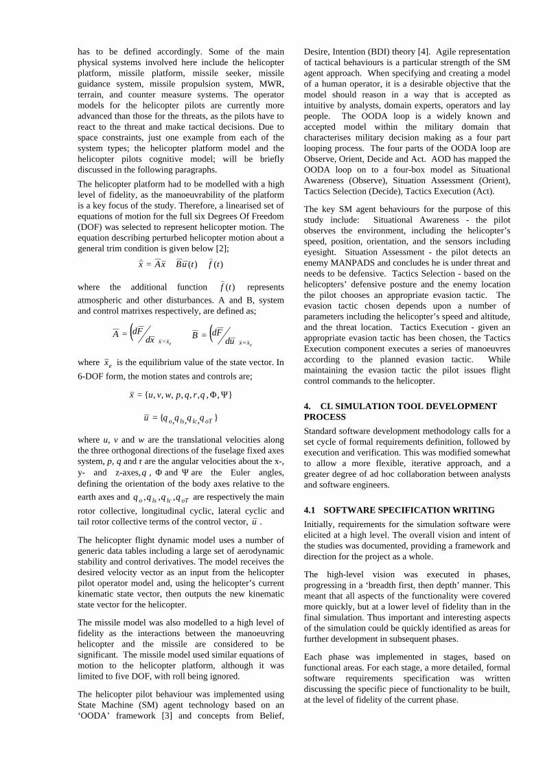
The helicopter platform had to be modelled with a high level of fidelity, as the manoeuvrability of the platform is a key focus of the study. Therefore, a linearised set of equations of motion for the full six Degrees Of Freedom (DOF) was selected to represent helicopter motion. The equation describing perturbed helicopter motion about a general trim condition is given below [2];
)()( tftuBxAx ++=&
where the additional function )(tf represents atmospheric and other disturbances. A and B, system and control matrixes respectively, are defined as;
( )exxxd
FdA=
= ( )exxud
FdB=
=
where ex is the equilibrium value of the state vector. In
6-DOF form, the motion states and controls are;
},,,,,,,,{ ΨΦ= θrqpwvux
},,,{ oTlclsou θθθθ=
where u, v and w are the translational velocities along the three orthogonal directions of the fuselage fixed axes system, p, q and r are the angular velocities about the x-, y- and z-axes,θ , Φ and Ψ are the Euler angles, defining the orientation of the body axes relative to the earth axes and oTlclso θθθθ ,,, are respectively the main
rotor collective, longitudinal cyclic, lateral cyclic and tail rotor collective terms of the control vector, u .
The helicopter flight dynamic model uses a number of generic data tables including a large set of aerodynamic stability and control derivatives. The model receives the desired velocity vector as an input from the helicopter pilot operator model and, using the helicopter’s current kinematic state vector, then outputs the new kinematic state vector for the helicopter.
The missile model was also modelled to a high level of fidelity as the interactions between the manoeuvring helicopter and the missile are considered to be significant. The missile model used similar equations of motion to the helicopter platform, although it was limited to five DOF, with roll being ignored.
The helicopter pilot behaviour was implemented using State Machine (SM) agent technology based on an ‘OODA’ framework [3] and concepts from Belief,
Desire, Intention (BDI) theory [4]. Agile representation of tactical behaviours is a particular strength of the SM agent approach. When specifying and creating a model of a human operator, it is a desirable objective that the model should reason in a way that is accepted as intuitive by analysts, domain experts, operators and lay people. The OODA loop is a widely known and accepted model within the military domain that characterises military decision making as a four part looping process. The four parts of the OODA loop are Observe, Orient, Decide and Act. AOD has mapped the OODA loop on to a four-box model as Situational Awareness (Observe), Situation Assessment (Orient), Tactics Selection (Decide), Tactics Execution (Act).
The key SM agent behaviours for the purpose of this study include: Situational Awareness - the pilot observes the environment, including the helicopter’s speed, position, orientation, and the sensors including eyesight. Situation Assessment - the pilot detects an enemy MANPADS and concludes he is under threat and needs to be defensive. Tactics Selection - based on the helicopters’ defensive posture and the enemy location the pilot chooses an appropriate evasion tactic. The evasion tactic chosen depends upon a number of parameters including the helicopter’s speed and altitude, and the threat location. Tactics Execution - given an appropriate evasion tactic has been chosen, the Tactics Execution component executes a series of manoeuvres according to the planned evasion tactic. While maintaining the evasion tactic the pilot issues flight control commands to the helicopter.
4. CL SIMULATION TOOL DEVELOPMENT PROCESS
Standard software development methodology calls for a set cycle of formal requirements definition, followed by execution and verification. This was modified somewhat to allow a more flexible, iterative approach, and a greater degree of ad hoc collaboration between analysts and software engineers.
4.1 SOFTWARE SPECIFICATION WRITING
Initially, requirements for the simulation software were elicited at a high level. The overall vision and intent of the studies was documented, providing a framework and direction for the project as a whole.
The high-level vision was executed in phases, progressing in a ‘breadth first, then depth’ manner. This meant that all aspects of the functionality were covered more quickly, but at a lower level of fidelity than in the final simulation. Thus important and interesting aspects of the simulation could be quickly identified as areas for further development in subsequent phases.
Each phase was implemented in stages, based on functional areas. For each stage, a more detailed, formal software requirements specification was written discussing the specific piece of functionality to be built, at the level of fidelity of the current phase.

Additional functional tests (not part of the main simulation) were created to exercise specific parts of the functionality in isolation. For example, the pilot terrain-following algorithm was studied in detail by creating a specific test harness that brought together the platform and terrain models. This allowed the effect of varying different parameters to be studied more easily, and proved to be very valuable in eliciting requirements for the main simulation.
This approach had the advantage of being able to deliver initial coarse results more quickly, which could then be used to direct subsequent, more refined development. It also helped to avoid wasting effort in areas that would later prove to be unimportant to the results of the study. Although this was a somewhat less formal method than that used in comparable studies, it retained the essential procedures necessary to produce verifiably correct results.
4.2 CL SIMULATION TOOL DEVELOPMENT
AOD has a number of CL Simulation tools available for studying the use of helicopters in combat. However none of them comprehensively met the requirements to support ARH studies within the Australian context.
The HORACE (UK OR model) model [5] focuses on helicopter encounters with land targets and/or threats. To do this it provides a detailed suite of tools for dynamic path planning. The path planning tools consider threats and terrain features which provide shadows for cover to minimise exposure. The costs of exposure to threats, various terrain types, and distance travelled can be varied to generate different paths. For example, a cautious pilot may prefer a longer path with less exposure to threats; while a pilot under time pressure may accept higher exposure to reach the end goal faster. However, the aerodynamic, sensors, and weapons modelling within HORACE are limited, which makes it unsuitable for detailed analysis of, for example, manoeuvring techniques or evasion tactics. Also the crew tactics modelled within HORACE are tailored to a select range of scenarios and cannot be readily extended.
The TRACES (US OR model) model focuses on considering helicopter tactics in air-to-air combat scenarios. To adequately model these scenarios TRACES contains a detailed helicopter aerodynamic model, which is capable of sophisticated control. However, TRACES has limited modelling of interactions with the ground environment or ground threats. This makes it unsuitable to, for example, model attack profiles which make use of ground cover. The crew tactics modelled within TRACES are also tailored to a select range of scenarios and cannot be readily extended.
DSTO has a number of sensor and weapon models which have been validated within the Australian context, such as the Generic Engagement Missile Model (GEMM) from DSTO WSD (Weapon System
Division); and IR and Flare models from DSTO EWRD (Electronic Warfare Radar Division).
In order to rapidly address helicopter tactics questions within the Australian context, AOD used the BattleModel simulation environment with reused components from HORACE (path planning), TRACES (aerodynamic model), and various DSTO tasks (sensors and weapons).
BattleModel is a flexible simulation environment suitable for performing OR. It was developed to support a wide range of studies from detailed engagement scenarios to mission level scenarios. BattleModel is used to manage the coordinated integration of sensor, weapon, platform, environment, and operator behaviour models, data collection, scenario specification, and display in an OR study.
BattleModel has been designed to provide an infrastructure that allows models to be integrated and pass data between each other in a modular way. By decoupling the models from the infrastructure in this way, models of varying fidelity, even for the same type of component, can be included in a single simulation. Figure 4 presents a conceptual view of the BattleModel infrastructure as the mechanism by which all components in a scenario communicate.
BM CoreInfrastructure
Sensors
Weapons
Platforms Crew
Terrain
AnalystEnvironment
CMComms
Figure 4: BattleModel Infrastructure
This allows a study to start with a basic BattleModel scenario composed of generic low or medium fidelity models and then extend the scenario with specific high fidelity models appropriate to the particular simulation requirements of the study. For example, a basic missile model was initially used to define and test the scenarios of interest for the current study. This model was then replaced with a model of greater fidelity for performing the actual study.
BattleModel also supports varying time fidelity. Models in a simulation may be executed at different simulation time fidelities. For example, initial studies were executed with a 0.5 second simulation frame time, this was found to be inadequate, and so the simulation frame time was then changed to 0.1 seconds.
4.3 CL SIMULATION TOOL VERIFICATION
In formal terms, verification is the process of demonstrating that the implemented software conforms to the specified requirements. The following methods were used:

• Unit tests, which exercise the capabilities of each software component in isolation;
• Integration tests, which exercise the functionality of integrated combinations of software components;
• System tests, which exercise the required functions of the system as a whole. These generally involved one or more runs of the simulation over a test scenario.
The majority of tests were automated using test harnesses and scripts. At each phase and stage, this suite of tests was augmented and updated to account for the functionality being added or modified. The entire set of tests was run prior to each release of the software. This ensured that any unintended side effects of modifications were exposed as soon as possible.
In addition, analysts conducted informal verification by using intermediate releases of the software prior to completion of each phase. This helped highlight issues that fell outside of the formally stated requirements.
4.4 CL SIMULATION TOOL VALIDATION
Once the simulation tool has been built and verified, it must undergo the validation process. Validation essentially determines the extent to which the simulation is an accurate representation of the real world. Clearly, the real world cannot be perfectly modelled in its entirety, and so validation provides a yardstick by which to measure the usefulness of the tool.
The validation of the simulation, as with most simulations, may be divided into two main parts, structural validation and output validation, with differing focuses as expected.
The structural validation starts even before the tool is fully built or verified, and can provide answers to various crucial development questions, for example:
• What impact do the linkages between the various models (flight, sensor, weapon systems etc) have on each other? Are there any unexpected synergies that could invalidate results?
• Is there a sufficient level of representation within the various models that comprise the tool? For example, do the six DOF aerodynamic models adequately represent the in-flight characteristics of the real helicopters?
• Does the tool possess a sufficient level of detail in those areas in which it is necessary; and equally, is there too much detail in unnecessary areas, thus making the simulation less efficient? Overall, is the simulation suitably balanced, without too great a bias in any single area?
Conversely, output validation begins once the tool (or at least the current version thereof) is finished. The aim of the output validation is to ensure that the results obtained compare satisfactorily with the real world, and also to ensure that the analysts understand both the results, and the reasons why the tool generated these particular results given the particular inputs used. It is essential that either the tool generates expected results, or that the reasons behind erroneous results can be fully explained.
Clearly, we are modelling a very complex situation and environment, and thus the requirements for comparing model results to real world results can be incredibly difficult, if not impossible, to satisfy. Two techniques are commonly used. The first, qualitative analysis, involves consultation with Subject Matter Experts (SMEs) to evaluate the accuracy of the simulation. Video-style replay functions are often invaluable in these cases. The second approach is that of quantitative, comparative analysis against other models or experiments, or against historical data where available.
5. AN EXAMPLE STUDY
A simple test study is described below to show how a validated CL simulation tool is used in OR studies. The study plan described in Section 2 was simplified by selecting the investigation of the safest helicopter formation for defensive helicopter tactical turns as the research objective, helicopter speed and separation distances as research variables, a reconnaissance mission as the test vignette and the helicopter survivability as research observable. Note that it is assumed that the helicopters are in combat spread formation (aircraft are side by side) and enemy MANPADS operators are instructed to hold fire for this vignette. The pilots are briefed to do maximum performance turns to evade if enemy are detected (Fig. 5). The helicopter survivability, Ps, is defined as the probability that the pilot does not crash the helicopter (into either the other helicopter or the ground) during this maximum performance turn.
Figure 5: Simple representation of an example study
The pilot who detects the MANPADS calls an immediate action message, “centre turn”, and initiates a maximum performance turn. The other pilot receives the message and starts the maximum performance turn with a small time delay, DT. DT is randomised with a mean representative value and a standard deviation.
V
A-Troop Leader B
MANPAD
D
V
H

The minimum safe helicopter separation distances (D) for all helicopter speed (V) settings have been explored here using the vignette described above. To this end, CL simulation runs have been performed for various initial separation distances, helicopter initial speeds and reaction times. For simplicity, the initial helicopter altitude, H, is selected to be high enough to avoid collision with the ground and DT equals to zero. The pilots perform coordinated centre turn manoeuvres only (no pedal turns) as their defensive tactic.
Figure 6 below illustrates a safe separation distance curve to summarise the results of these simulation runs. If flying in combat spread formations with separation distances shorter than those shown by this safe distance curve, the helicopters are in danger of colliding with each other in defensive centre turn manoeuvres. Note that this curve is valid for combat spread formation only and will change if the helicopters are in combat cruise formation. As expected, when the helicopter speed is increased, the minimum separation distance required to avoid collision increases. The safe separation distance curve values vary from around 50m for low speeds to around 1500m for higher speeds.
0 50 100 150
Figure 6: Minimum safe separation distance curve for helicopter defensive centre-turn manoeuvre
To generalise further, one can define the area above this safe separation distance curve as safe to operate within, and the area below as unsafe. If the current helicopter speed and separation distance values fall in the unsafe area of the curve, the pilot should not consider a centre turn manoeuvre. Note that the results presented in this paper are generic only and do not represent any real system.
6. DISCUSSION
CL simulation tools and HIL simulation tools complement each other well. CL simulations are fast, repeatable, controllable and readily adaptable for use in OR studies. HIL simulations are very strong in cognitive behaviour representation since humans are involved in the decision making process. HIL simulations occur in real time. CL simulations appear to be more appropriate than HIL simulations for use in initial tactic development studies if the available tactic development time is short. HIL simulations can then be used for spot validation of the statistical results generated from CL simulations by narrowing the scope of the experiments. Note that generating a response to the OR question described in section 5 with the CL simulation tool
discussed in this paper took only two days of effort, since the simulations run faster than real time and could run 24 hours a day. If we responded to the same OR question with a HIL simulation tool, it would take a couple of months to get a similar curve to that in figure 6 due to system preparation time, pilots’ familiarisation time to the systems, pilots’ travel time to the simulation facilities, total HIL flight simulation time etc.
Representing tactical behaviours is a challenge in modelling helicopter air operations. The architecture used here gives advantages over other OR models in power of representations, flexibility in chancing tactics, engineering efficiencies in maintenance and most importantly in transparency how the results relate to pilot decision making. We have built a technical base that allows us to move from simple troop manoeuvre to more complicated team interactions (in both blue and red sides).
Building a capability of the kind described here has engendered a good dialog with the military client. The OR work is complemented by a coordinated HIL capability elsewhere in DSTO.
REFERENCES 1. Ibal G.; Selvestrel M.; et. al. (2004) “Air
Operational Research in Support of Helicopter Defensive Tactic Development” Proceedings of the Ninth SIMTEC, May.
2. Gareth D. P., “Helicopter Flight Dynamics: Theory
and Application of Flying Qualities and Simulation Modeling”, AIAA Education Series, J.S. Przemieniecki, Series Editor-in-Chief, Air Force Institude of Technology, Ohio, USA.
3. Heinze C., Cross M, Goss S., Josefsson T., Lloyd I.,
Murray G., Papasimeon M., and Turner M. (2002) “Agents of change: The impact of intelligent agent technology on the analysis of air operations”, In L. Jain, N. Ichalkaranje, and G. Tonfoni, editors, Advances in Intelligent Systems for Defence, volume 2 Series on Innovative Intelligence, chapter 6, pages 229-264. World Scientific, River Edge, New Jersey, USA, 1 edition, December.
4. Selvestrel M., Harris E. and Ibal G. (2004) “SM
Agent Technology For Human Operator Modelling”, Proceedings of the Ninth SIMTEC, May.
5. Arney A., Selvestrel A., Lawrence M., Mockridge
L. (2001) “Modifications made to HORACE package since acquisition from DERA UK” Discussion Paper, DSTO-DP0673 October.
SAFE (Ps>0.99)
UNSAFE
Helicopter cruise speed (kn)