closed circuit current monitoring - internet archive
TRANSCRIPT

Subject Page
Introduction ..........................................................................................2
Purpose of the System........................................................................ 3
Power Supply Circuit........................................................................... 4
Power Module.......................................................................................5Inputs.....................................................................................................8Outputs..................................................................................................9
Shut Down Protocol............................................................................10
Closed-Circuit Current MonitoringNormal Sleep Mode...............................................................................11Storage Mode.......................................................................................14
Check Control Messages...................................................................15
Workshop HintsClosed-Circuit Current Monitoring.........................................................16Preconditions & General Observations..................................................17Closed-Circuit Current Monitoring Procedure........................................18Diagnosing the Power Module with the DISplus/GT1............................23Battery Replacement Registration.........................................................29Diagnostic Test Plans............................................................................32
Review Questions...............................................................................33
Table of Contents
Closed Circuit Current Monitoring

2Closed Circuit Current Monitoring
Closed Circuit Current Monitoring
Model: E65 - 745i / E66 - 745Li
Production Date: 11/2001 - E65, 03/2002 - E66
Objectives of The Module
After Completing this module, you will be able to:
• Explain what the Power Module uses to calculate the optimum charge voltage.
• Identify when the battery switch is left in the “OFF” position.
• Perform the Battery Replacement Registration after replacing a battery.
• Understand a normal Shut Down Protocol and identify a violation.
• Identify 2 “visuals” that indicate the vehicle is entering sleep mode.
• List the final Closed-Circuit Current draw on a “normal” vehicle.
• Explain what Special Tool #90 88 6 612 310 is used for and demonstrate it’s use.

3Closed Circuit Current Monitoring
Purpose of The System
This module describes the technical changes that have been made to the Power Modulerelevant to fault codes and diagnostic service procedures. You should be familiar with thebasic operation covered in the E65 Complete Vehicle course (ST042). Additional informa-tion is now available for:
• Closed circuit current monitoring• Check Control messages• Battery replacement
The Power Module ensures that the battery charge level is maintained when the engine isrunning and when the vehicle is at rest. The Power Module is also responsible for main-taining the power supply (in the event of faults in the electrical system) to important vehiclesystems by disconnecting lower priority circuits.
Power Module Functions
• Optimum charging.• Load-circuit peak reduction.• Shut-down of auxiliary consumer
circuits in the event of low voltage.• Closed circuit current monitoring.• Distribution mode.• Automatic electrical system isolation.• Load cutout.• Electronic fuses.
System Components
• Power Supply circuit
• Fuses
• Power Module- Electronic battery master switch- High-current sockets- Inputs- Outputs connected to electronic battery master switch- Outputs not connected to electronic battery master switch- Electronic control unit
• Central battery voltage notification.• Rear window defogger output.• Interior lighting control.• Trunk lid and fuel filler flap control.• Data memory storage.• Emergency-mode functions.• Check Control messages.• Diagnosis.

4Closed Circuit Current Monitoring
Power Supply Circuit
The power supply for the general electrical system is controlled by the Power Module. Thehigh amperage fuses in the engine compartment, the alternator and the starter motor areconnected directly to the battery and not supplied by the Power Module.
420805
2

5Closed Circuit Current Monitoring
Power Module - Location and Construction
The Power Module on the E65 is located on theright-hand side of the luggage compartment.
1. Cover plate
2. Electronics
3. Electronic Battery Master switch
4. Heat sink
KL 30, KL 30B and KL 30U = High-Current Terminals
Electronic Battery Master Switch
The electronic battery master switch is made up of 4 MOS-FET output stages (S Bat) andconnects the input terminal 30 with the outputs KL 30U and KL 30B on the Power Module.The following functions are controlled by means of the Power Module according to the posi-tion of the battery switch:
• Storage mode • Electronic fuses• Closed circuit current monitoring • Automatic electrical system isolation
High-Current Terminals (RADSOK)
New high-current terminals are used in the E65/E66. The high-current terminals are on theinput terminal 30 and the outputs terminal 30U and terminal 30B. These contacts are capa-ble of carrying current peaks (short term) of 220 A.
KT-8355
KT-7741
U
B

6Closed Circuit Current Monitoring
Inputs/Outputs
KT-8350
Battery Switch
Battery
K-CANPeriphery
Wake-up inputfrom CAS
Interior lightswitch
External trunkrelease button
Battery Temp.Sensor
Terminal 30outputs
HHS=Rear window defogger.
LM=Lamp Module.DME=ECUCAS=Car Access
SystemDWA=Alarm C.U.DWA NS=SireneIR=Not used in U.S.
Terminal 15 outputs
ZIG=Cig. lighter relayUFBD=Universal
remote control.EC=Electrochromatic
mirrors.PDC=Park Distance
Control.
Terminal Routputs
RLS=Rain/Light Sensor
(IB) Interior Lighting
(VA-D)ConsumerIsolationCircuit/Roof
(VA-K)ConsumerIsolationCircuit/Body
SCASoft CloseActuator (Trunk)
ZVCentral lockActuator (trunk)
TKLCentral lockActuator (Fueldoor)

7Closed Circuit Current Monitoring
Detailed view of Power Module
KT-8349
X18
56 3
2 P
in c
onn
ecto
rX
1857
13
Pin
co
nnec
tor
X18
58
3 P
in
Co
nnec
tor
(Tem
p. S
enso
r)
X18
59 2
pin
conn
ecto
r(H
HS
and
LM
)

8Closed Circuit Current Monitoring
Inputs
Terminal 30The battery positive terminal is connected directly to the load input of the Power Module.
Battery SwitchThe battery switch (BS) offers the vehicle owner and the service department the choicebetween the settings ON ("closed circuit current monitoring") and OFF ("storage mode"). Itis located above the PM on the right hand side of the luggage compartment.
Interior Lighting ButtonThis controls the interior lighting and is located on the front interior lighting unit. The possi-ble settings are "Automatic control", "On", "Off" and “Workshop mode” (hold for 3 sec-onds).
Exterior Trunk Lid Release Button (TOEHK)This button is a direct input to the Power Module. The trunk lid is released by means of thebutton on the outside of the trunk lid.
Trunk Lock Actuator SwitchThe switch in the trunk lock actuator is used to inform the Power Module as to the positionof the lock actuator and to synchronize the SCA. it also controls the luggage compartmentlighting, the monitoring of the alarm system and the trunk lid warning light.
SCA ContactThis input is used to signal the PM that the SCA has rotated 1800 (used to switch off theelectric motor).
15_w (wake-up)This is a redundant signal from the Car Access System which wakes up the Power Module.
Battery Temperature SensorMeasures the temperature directly on the battery negative terminal. This information is usedfor the "optimum charging" function. The measuring range is -25OC to +75OC.
K-CAN PeripheryEnables communication with the vehicle network.
KT-8288

9Closed Circuit Current Monitoring
Outputs Connected to Electronic Battery Master Switch
Terminal 30USupplies the fuse box in the luggage compartment.
Terminal 30BSupplies the fuse box in the glove compartment.
Outputs Not Connected to Electronic Battery Master SwitchThe following outputs are supplied by the PM separately from the Electronic Battery MasterSwitch.
• Rear window heater (HHS)• Light Module (LM)• Car Access System (CAS)• DME• Alarm system (DWA)• Emergency power siren (SINE)• Cigarette lighter (ZIG)
The advantages of this arrangement are:
• The exterior lighting can remain on (for safety reasons) even if the Electronic Battery Mas-ter switch is off.
• The alarm system is always armed.• No additional fuses and wiring for actuators in nearby locations.
• Electrochromatic mirrors (EC)• Park Distance Control (PDC)• Rain/light sensor (RLS)• Interior lighting (IB)• Central locking trunk lid drive (ZV)• Central locking, fuel filler flap (ZV)• Trunk lid Soft Close Motor (SCA)
Battery Switch
Terminal 30Terminal 30 U
Terminal 30 B

10Closed Circuit Current Monitoring
FusesThe outputs for the rear window heater, KL R and KL 15, are not protected by convention-al fuses. They are supplied via a power transistor (MOS-FET) in the Power Module.
By measuring the current and comparing it with stored threshold levels, the Power Modulecan detect a short circuit and disconnect the circuit if needed. The outputs for CAS, DWAand DME are protected by internal electronic fuses.
Shut Down Protocol
Shut-Down of Consumer Circuits (Sleep mode)
To prevent battery discharge by consumer items mistakingly left on, the interior lighting cir-cuit (IB) and consumer circuits-roof zone (VA-D) aarree sshhuutt ooffff 1166 mmiinnuutteess aafftteerr KKLL RR iisssswwiittcchheedd ooffff..
The consumer circuit-body (VA-K) remains on longer for the cigarette lighter relay, gloveboxlighting, luggage compartment light and the telephone (recharging if plugged in). The VA-Kiiss sshhuutt ooffff 6600 mmiinnuutteess aafftteerr KKLL RR iiss sswwiittcchheedd ooffff..
Shut-Down of Auxiliary Consumers
In order to ensure that the car is capable of starting, the charge level (SoC-State of Charge)of the battery is monitored when the vehicle is at rest. The minimum battery SoC requiredto ensure that the car can be started again is a calculated value.
The calculation takes into account the:
• Battery temperature measured over last few days• Engine type • Capacity of the battery fitted (110Ah for the 745i).
The SoC calculation is displayed as a percentage of battery capacity (a fully charged bat-tery is considered 80%). If the charge level of the battery gets close to that calculated min-imum level as a result of the operation of an auxiliary consumer unit, the Power Moduleinstructs that circuit to switch off.
Auxiliary consumer circuits are items such as the Control Display, DWA, LM, EGS and IHKA(rest function). There are two modes of operation when shutting down auxiliary consumercircuits: auxiliary consumers with KL R “ON” and auxiliary consumer with ignition off (KL 0).
11Closed Circuit Current Monitoring
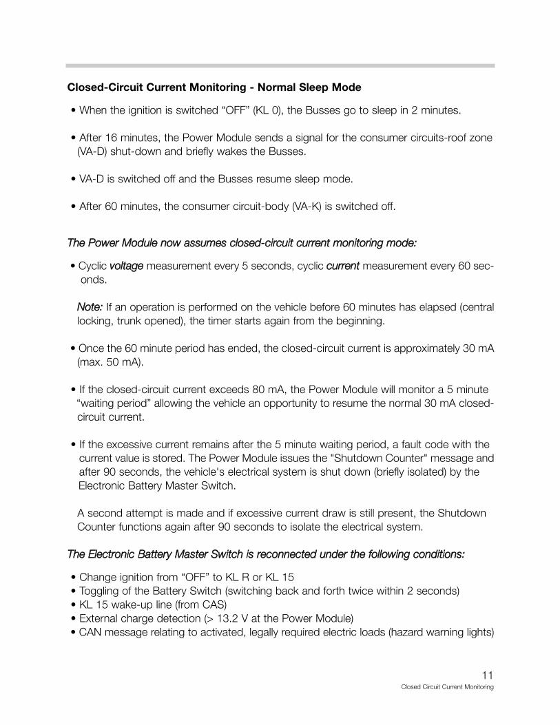
Closed-Circuit Current Monitoring - Normal Sleep Mode
• When the ignition is switched “OFF” (KL 0), the Busses go to sleep in 2 minutes.
• After 16 minutes, the Power Module sends a signal for the consumer circuits-roof zone (VA-D) shut-down and briefly wakes the Busses.
• VA-D is switched off and the Busses resume sleep mode.
• After 60 minutes, the consumer circuit-body (VA-K) is switched off.
TThhee PPoowweerr MMoodduullee nnooww aassssuummeess cclloosseedd--cciirrccuuiitt ccuurrrreenntt mmoonniittoorriinngg mmooddee::
• Cyclic vvoollttaaggee measurement every 5 seconds, cyclic ccuurrrreenntt measurement every 60 sec- onds.
NNoottee:: If an operation is performed on the vehicle before 60 minutes has elapsed (central locking, trunk opened), the timer starts again from the beginning.
• Once the 60 minute period has ended, the closed-circuit current is approximately 30 mA (max. 50 mA).
• If the closed-circuit current exceeds 80 mA, the Power Module will monitor a 5 minute “waiting period” allowing the vehicle an opportunity to resume the normal 30 mA closed-circuit current.
• If the excessive current remains after the 5 minute waiting period, a fault code with the current value is stored. The Power Module issues the "Shutdown Counter" message and after 90 seconds, the vehicle's electrical system is shut down (briefly isolated) by the Electronic Battery Master Switch.
A second attempt is made and if excessive current draw is still present, the Shutdown Counter functions again after 90 seconds to isolate the electrical system.
TThhee EElleeccttrroonniicc BBaatttteerryy MMaasstteerr SSwwiittcchh iiss rreeccoonnnneecctteedd uunnddeerr tthhee ffoolllloowwiinngg ccoonnddiittiioonnss::
• Change ignition from “OFF” to KL R or KL 15• Toggling of the Battery Switch (switching back and forth twice within 2 seconds)• KL 15 wake-up line (from CAS)• External charge detection (> 13.2 V at the Power Module)• CAN message relating to activated, legally required electric loads (hazard warning lights)

12Closed Circuit Current Monitoring
When the signal “15w” from the CAS is detected, the Electronic Battery Master Switch isclosed and the following Check Control message is displayed:
Closed-circuit current monitoring is automatically cancelled by a message from the LampModule that the hazard warning lights are active.
When KL R is switched off, current monitoring is also immediately activated. Normal cur-rent load on the vehicle drops in stages according to the vehicle programming for sleepmode (see chart on the following page).
If the monitored current is > 120 amps (even as a random spike) , the interior lighting, roofarea consumers and body zone consumer circuits are immediately switched off.
Reasons for Electronic Battery Master Switch Disconnection
The reason for battery disconnection is stored together with the fault code in the PowerModule fault memory. Several examples that may be stored are:
• The battery was disconnected because a current > 120 Amps was measured after switching off KL R.
NNoottee:: The current threshold was increased from 35 Amps to 120 Amps because all four power window motors can be operated simultaneously up to the end stop.
• The battery was disconnected because an excessively high vehicle closed-circuit current was measured.
• The battery was disconnected after a 3 week parking period.
• The battery was disconnected by activation of Storage Mode with the Battery Switch.
• The battery was disconnected because the battery capacity (SoC) dropped below the start limit with KL R switched on and KL 15 switched off.
• The battery was disconnected because a short-circuit in KL 30 was detected.
• The battery was disconnected by a DISplus/GT1 diagnostic command.
Check Control Message Message displayed in Causedisplayed in KOMBI Control Display
High standby current! High standby current! Excessive closed-Vehicle electrical accessories circuit current draware drawing excessive passive-statecurrent. Battery has been disconnectedPlease contact your BMW center.

13Closed Circuit Current Monitoring
800
mA
200
mA
25 s
eco
nds
16 m
inut
es60
-70
min
utes
30 m
A
Bus
com
mun
icat
ion
ende
d: V
ehic
le in
sle
ep m
ode!
In
dica
tor:
CA
S li
ght
out,
BZM
ligh
ts o
n
Sle
ep m
ode:
VA
-D (c
onsu
mer
circ
uit-
roof
) sw
itche
d of
fIn
dica
tor:
CA
S, B
ZM li
ghtin
g (s
eat
switc
hes)
out
, tru
nk li
ght
out
and
Nav
i Cha
nger
LE
D o
ut.
Sle
ep m
ode:
VA
-K (c
onsu
mer
circ
uit-
body
)sw
itche
d of
f. A
ppro
x. 3
0 m
A (
norm
al p
eaks
last
for
appr
ox. 2
0 se
cond
s ea
ch)
• C
igar
ette
ligh
ter
rela
y•
Tele
phon
e •
Pow
er M
odul
e
Clo
sed
-Cir
cuit
Cur
rent
Mo
nito
ring
and
Veh
icle
Sle
ep M
od
e16
A
Bus Telegram: “Sleep Counter” approx. 8-9 A for 30 seconds, CAS light on

14Closed Circuit Current Monitoring
Storage Mode
By switching “OFF” the battery switch, the PowerModule goes into Storage Mode 30 minutes afterterminal R switches off.
Before disconnecting, the PM sends out the "Shutdown" signal. After a further 90 secondsthe shut down is completed. If the ignition switch is turned to KL R or KL15, a CheckControl message is issued which informs the driver that the vehicle is in Storage Mode.
The following CC message appears:
When the signal “15w” or change-over of the battery switch to "closed-circuit current mon-itoring" is detected, the Electronic Battery Master Switch is closed.
TThhee vveehhiiccllee ccaann ssttiillll bbee ssttaarrtteedd aanndd ddrriivveenn iinn ssttoorraaggee mmooddee.. All systems remain functional. The CC message remains active.
When KL R “Off" is active, disconnection is carried out after 30 minutes (as explainedabove).
NNoottee:: If the battery switch is detected as defective, closed-circuit current monitoring will beactivated.
IIff nnoo ffuunnccttiioonn ooff aannyy kkiinndd iiss aaccttiivvaatteedd oovveerr aa ppeerriioodd ooff 33 wweeeekkss,, tthhee bbaatttteerryy iiss ddiissccoonnnneecctteeddffrroomm tthhee vveehhiiccllee''ss eelleeccttrriiccaall ssyysstteemm ttoo pprreevveenntt bbaatttteerryy ddiisscchhaarrggee.. TThhiiss ffuunnccttiioonn iiss iinnddeeppeenn--ddeenntt ooff tthhee ppoossiittiioonn ooff tthhee bbaatttteerryy sswwiittcchh..
Electronic Fuse
If a short circuit current of over 250 A is detected, the Electronic Battery Master Switch isopened. When the wake-up signal “15w” from the CAS is detected, then an attempt ismade to close the Electronic Battery Master Switch again.
This procedure is repeated continually until the short circuit has been eliminated.
OFF
KT-8288
Check Control Message Message displayed in Causedisplayed in KOMBI Control Display
Battery switch OFF ! Battery switch OFF! Battery switch left in Re-set battery switch in luggage OFF position.compartment to ON, refer toowners manual.

15Closed Circuit Current Monitoring
Check Control Messages
The following are Power Module relevant messages:
NNootteess::
Check Control Message Message displayed in Causedisplayed in KOMBI Control Display
Battery Switch OFF! Battery switch OFF! Battery switch left in Re-set battery switch in luggage OFF position.compartment to ON, refer toowners manual.
High standby current! High standby current! Excessive closed-Vehicle electrical accessories circuit current draw.are drawing excessive passive-statecurrent. Battery has been disconnectedPlease contact your BMW center.
Recharge Battery! Recharge battery! Battery dischargedBattery heavily discharged.Charge by driving for longer periodor by using external charger. Battery will be disconnected soon.
Power Module! Power module in emergency ! Power module indrive moderately operating mode. Electrical emergency mode
power supply limited. Pleasecontact the nearest BMW center.
Power Module failure! Power module failure! Power module aliveAutomatic monitoring of signal missing over
battery charge level failure. bus line.Please contact the nearest BMW center.

16Closed Circiut Current Monitoring
Workshop Hints
Closed Circuit Current Monitoring For The E65/E66 Electrical System
In the event that an E65/E66 vehicle has a battery draw and/or the Power Module has faultsstored in memory relative to closed circuit current monitoring, the following is provided toassist you in diagnosis.
Increased closed-circuit currents may occur permanently or occur intermittently, and causethe battery to discharge prematurely. The increase in closed circuit current may be causedby a faulty control module, or by the installation of a non-approved accessory.
In a situation where a vehicle has compalints due to a discharged battery, for diagnosticpurposes it is important not to disconnect the battery. This is because a control module willbe reset if the battery is disconnected. Following a reset, the faulty control module may startfunctioning correctly again, making accurate diagnosis impossible.
To correctly measure closed-circuit current, measurement adapter Special Tool PP//NN 9900 888866 661122 330000 should be used. This tool provides a bridge to ground, before the negative bat-tery terminal is disconnected, and this prevents the control modules from being reset.
The additional use of MoDiC adapter Special Tool PP//NN 9900 8888 66 661122 331100 provides a methodfor current measurements over an extended period of time.
This procedure should be followed after you have reviewed the Power Module “Principle ofOperation” in the beginning of this module.
Tools Required:• 50 amp inductive probe for DISplus or MFK1
for the MoDIC/GT1.
• BMW closed circuit current measuring tool # 61 2 300 (4. in diagram).
• Digital Multimeter capable of measuring up to 15 Amps.
• MoDIC adapter # 61 2 310 for recording draws up to 72 hours (3. in diagram).

17Closed Circiut Current Monitoring
Preconditions:• First, rreeaadd aanndd uunnddeerrssttaanndd SSIIBB ## 6611 0088 0000
• Charge the vehicle battery with a BMW recommended (Deutronic) battery charger to obtain a minimum of 12.6 Volts. The battery charger must be disconnected prior to any draw testing.
• Vehicle charging system must be operating correctly.
• Ceck for faults and correct any faults that are present.
• Have a copy of the bus chart ready for reference. Understand the basics in order to “Divide and Conquer” the bus network.
• Review the power supply wiring diagram to understand the three (3) separate routes that the B+ potential can travel. The B+ lead that feeds the IVM/ECM, starter and generator. This lead has a junction in the luggage compartment and supplies the aluminum ribbon cable to the front of the vehicle.
The second is the feed from the Power Module 30 B to the front fuse panel in the glovebox. Moving the current probe to each individual cable will isolate which circuit has the current draw(s).
• Review the Vehicle Sleep Mode shut down protocol chart (page 13) to assist with com- parisons when diagnosing a faulted vehicle.
Please Review the Following General Observations:
1. After swithcing the ignition “OFF”, the CAS light remains “ON” for approximately 2 min-utes. When the CAS LED goes out, this indicates that the Bus network is sleeping. At this time the current measurement should not be > 800 mA (.8 A).
2. After approximately 16 minutes the CAS led illuminates for approximately 30 seconds (Bus network is awake). After the CAS LED goes out (Bus network is sleeping), the BZM seat switch lights (left and right) will turn off. At this time the Power Module circuit VA-D roof consumers shut down (hint - leave a map light on as a visual). The current draw is approximately 200 mA (.2 A) at this time.
3. The remaining time until the vehicle is in “sleep mode” will occur in approximately 44 minutes (vehicle dependent). The total time for sleep mode could take up to 70 min-utes.
18Closed Circiut Current Monitoring
4. The final closed circuit current draw should be approximately 30 mA (.030 A) or less (normal peaks last for approx. 20 seconds each). These normal peaks are a result of the Instrument Cluster performimg a temperature status check (deminishes in frequency as time goes on).
5. Always allow the vehicle to go into the sleep mode naturally. Do not use the DISplus/GT1 test module to expedite shut down on the initial diagnosis. This test module can be used after the conformation of failure has occurred and additional testing is required. This will help in speeding up the subsequent diagnosis.
Closed Circuit Current Monitoring Procedure:
The following instructions can be supplemented with the HI document in DIS under Powersupply Diagnostic Test Plan, entitled ““PPrroocceedduurree iinn eevveenntt ooff cclloosseedd cciirrccuuiitt ccuurrrreenntt ffaauullttss””..There are examples of closed-circuit current violations with additional diagnostic hints.
1. With the DISplus/GT1, interrogate all control modules with a short test. Correct all faults before proceding with closed circuit diagnosis. This includes reviewing diagnostic queries for the Power Module to analyze reasons for battery disconnects, battery SOC, battery history and basic charging operation.
2. Disconnect battery charger from the vehicle (remove clamps).
3. Open the trunk lid and secure the latch mechanism (as if the trunk lid was closed).
4. Open hood and lift up on the hood pin switch (service position).
5. To prepare for fuse access, open the glove box door and disable the glovebox light. This will avoid awakening the Power Module later.
6. Hook up current monitoring tools following this progression:
IIff uussiinngg tthhee DDIISSpplluuss::- 50 amp inductive clamp around the B- cable from the battery to chassis ground.
Access the BMW Test system ““MMuullttiimmeetteerr ssccrreeeenn““, and select the ““CCuurrrreenntt 5500AA”” set- ting and ““MMIINN//MMAAXX””.
PPrreeffeerreedd -- MMooDDIICC//GGTT11 (when function is available on GT1)- 50 amp inductive clamp around the B- cable from the battery to chassis ground.
- MFK1 connected to Special Tools # 61 2 300 and # 61 2 310 (as shown on page 16).Follow MoDIC setup instructions per SIB # 61 08 00 (do not plug into MoDIC yet, just have connections ready), ddoo nnoott ddiissccoonnnneecctt tthhee cchhaassssiiss ggrroouunndd aatt tthhiiss ttiimmee.. This tool can only handle a current of 10 amps or less and will fail until the vehicle current is safely below this value.

19Closed Circiut Current Monitoring
7. Shut off ignition “KL 0”, remove the remote key from vehicle. Open both front doors and secure rotatory latch (as if the doors were closed), UUssee aa ssuuiittaabbllee ttooooll aanndd nnoott yyoouurr ffiinn--ggeerr!! BBee ccaarreeffuull nnoott ttoo ccaattcchh yyoouurr ffiinnggeerrss iinn tthhee llaattcchh,, tthhee vveehhiiccllee mmaayy bbee eeqquuiippppeedd wwiitthh SSoofftt CClloossee AAuuttoommaattiicc ((SSCCAA)).. Activate the remote locking “twice” (to disable the FIS sen-sor) and begin to watch for Bus power down.
8. After the CAS LED goes out (approx. 2 minutes), the current draw should not be > 800 mA. The BZM lights will remain on.
9. After approximately 16 minutes, the CAS LED will illuminate. The current draw will spike to approximately 8 - 9 A for 30 seconds. Then the CAS and BZM lights go out and the current draw will be approximately 200 mA for 60 -70 minutes. UUnnpplluugg tthhee 5500 aammpp ccllaammpp lleeaadd ffrroomm tthhee MMooDDIICC aanndd pplluugg iinn tthhee MMFFKK11 lleeaadd,, iitt iiss nnooww ssaaffee ttoo rreemmoovvee tthhee cchhaassssiiss ggrroouunndd aanndd tthhee ddrraaww ttrraaccee wwiillll bbeeggiinn iiff tthhee MMooDDIICC//GGTT11 iiss uusseedd..
At the 60 -70 minute point (sleep mode), if the closed-circuit current draw is > 30 mA, normal procedures of pulling fuses and disconnecting components will be necessary (as outlined below). Remember to divide and conquer the circuits with the help of the ETM.
IIff tthhee cclloosseedd--cciirrccuuiitt ccuurrrreenntt ddrraaww rreemmaaiinnss hhiigghheerr tthhaann 3300 mmAA aafftteerr 6600 mmiinnuutteess oorr nneevveerrddrrooppss ddoowwnn ttoo lleessss tthhaann 3300 mmAA pprroocceeeedd aass ffoolllloowwss ((tthhee MMooDDIICC//GGTT11-- when function is avail-able on GT1, mmuusstt bbee uusseedd aatt tthhiiss ppooiinntt ttoo eessttaabblliisshh aa ddrraaww ttrraaccee))::
10. Remove Fuse 5 from the front fuse box behind the glove compartment (Fuse 5 also powers the BZM, the seat switch lights will go out). Wait 2 minutes (allows CAS to reset) and recheck draw.
If draw drops down to below 30 ma reinstall Fuse 5 and disconnect 1 MOST bus con-sumer at a time (Control Display last - it is the gateway) and install optic jumper (made from parts, available in EPC) wait 2 minutes between each disconnection (allows CAS to reset).
11. If draw is still present after Fuse 5 removal, remove Fuse 15 to ZGM from front fuse box, this isolates the Byteflight Bus from PT-CAN Bus.
If draw drops down, then disconnect SIM module behind glove box and reinstall Fuse 15. If draw drops after SIM removal then draw is from Byteflight and isolate which Byte- flight module is causing draw. If draw does not drop after SIM removal, the draw is com-ing from PT-CAN bus. Disconnect each PT-CAN Bus module until draw is gone.
12. If removing Fuse 5 and or Fuse 15 do not drop draw below 30 mA, then draw is from K-CAN S and or K-CAN P modules. Disconnect one CAN consumer at a time until draw is gone.
NNoottee:: Please refer to Bus Chart on page 20.
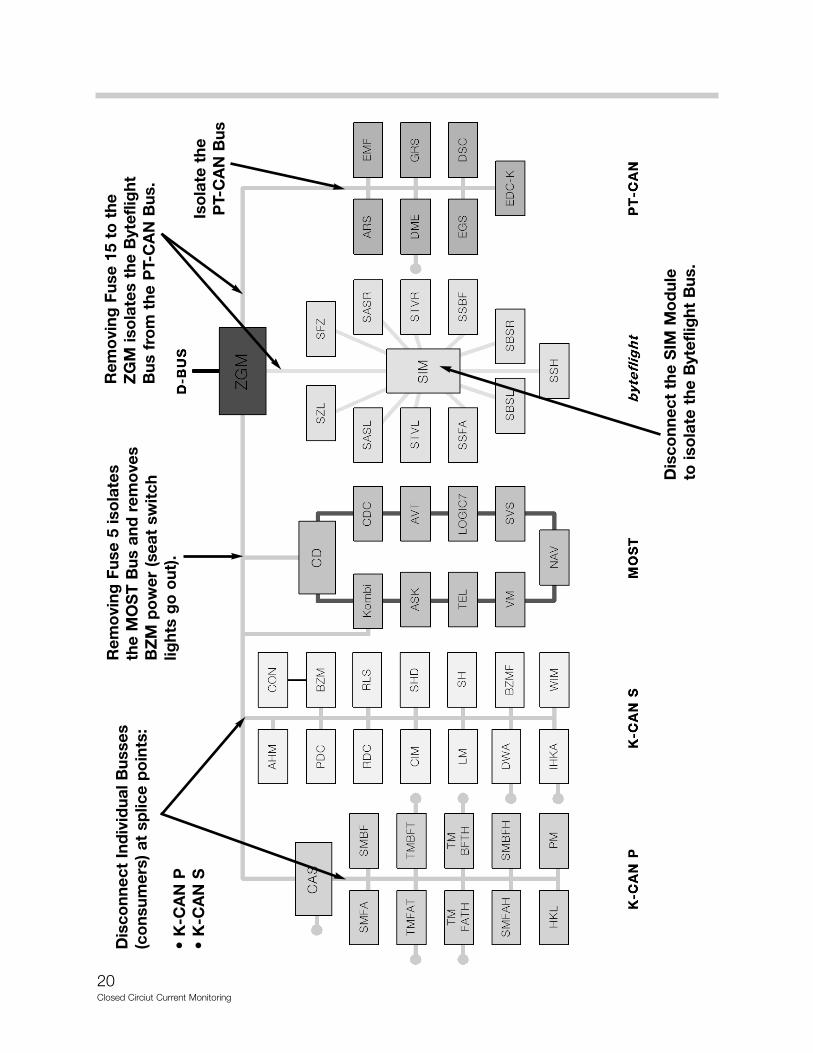
20Closed Circiut Current Monitoring
Dis
conn
ect
Ind
ivid
ual B
usse
s(c
ons
umer
s) a
t sp
lice
po
ints
:
• K
-CA
N P
• K
-CA
N S
Rem
ovi
ng F
use
5 is
ola
tes
the
MO
ST
Bus
and
rem
ove
sB
ZM
po
wer
(se
at s
wit
chlig
hts
go
out
).
Dis
conn
ect
the
SIM
Mo
dul
eto
iso
late
the
Byt
eflig
ht B
us.
Iso
late
the
P
T-C
AN
Bus
Rem
ovi
ng F
use
15 t
o t
heZ
GM
iso
late
s th
e B
ytef
light
Bus
fro
m t
he P
T-C
AN
Bus
.

21Closed Circiut Current Monitoring
Closed Circuit Current Monitoring Flow Chart
Key Off = KL”0”, Wait 2 min. is the CAS LED Out?
YYEESSWait for 16 minutes.Is the BZM light out?
NNOORemove Fuse #15
powering ZGM.
Wait 2 Minutes forCAS light to go out.
Is CAS light out?
YYEESSFault is in ByteFlight or PT-CAN Bus
awakening all Busses.
Reinstall Fuse #15 and unplug SIM,wait 2 minutes.
Is the light out?
NNOOReinstall Fuse #15.
Remove Fuse #5wait 2 min. & watch
current draw.
NNoottee::BZM light will not
function with Fuse #5out, however CASlight will function.
CAS light out?
YYEESSMost Busconcern.
UnplugControl Modules
with 2 min.wait between,until isolated.
NNOOReinstallFuse #5.
RemoveK CAN-SLow/Highwires from
CAS X10318.
Term 13 (green)
Term 14(green/orange)
YYEESSFault is in ISIS
circuit.
Isolate byunplugging
each Satelliteand waiting
2 min. betweeneach unplug.
Recheck drawafter 1 hourto validate.
Use PMService Function
Shut Downto validateinstead of waiting full
60 miniutes
NNOOFault is in the
PT-CAN.
Isolate byunplugging
each moduleuntil isolated.
Wait 2 min.between each
module unplug.
YYEESSPM is shuttingdown wait full60 min. and
monitor currentdraw.
Is current< 30 mA?
NNOOBZM
light not out.PM shut down
is not occurring
(circuit VA-D).
Review PMoperation.
UseComponentActivation to
check possiblePM faults.
YYEESSOOKK
NNOO> 30 MA
Isolate currentdraw.
Remember touse 30U/30Bcable to help
determine draw(front to rear).
Check individualcircuits that areisolated from
30U/30B (LM, DWA, alt,aux. fan, etc).
YYEESSIsolate
K-CAN Pcomponentsas outlinedin previous
steps.
NNOOIsolate
K-CAN Scomponentsas outlinedin previous
steps.
Is lightout in 2 min?

22Closed Circiut Current Monitoring
Sleep Mode with PT-CAN Bus Consumer (example)
When the closed-circuit current draw remains higher than 30 mA after 60 minutes or neverdrops down < 30 mA, the MoDIC/GT1 (when function is available on GT1) used at this pointestablishes a draw trace.
In this example, a consumer stays awake after the 60 -70 minutes. From the peaks you canobserve that the closed-circuit current draw is not normal.
By removing Fuse #15 to ZGM (in front fuse box), the Byteflight and PT-CAN Bus circuitsare isolated and the closed-circuit current draw decreases to a normal value.
After disconnecting SIM module and reinstalling fuse #15, the draw still exists indicatingthat it is from PT-CAN bus.
By disconnecting each PT-CAN Bus module (one at a time), the draw decreased after theElectro-mechanical Parking Brake Control Module (EMF) was unplugged. This componentwas staying awake and in addition, awoke the entire Bus network.

23Closed Circiut Current Monitoring
Diagnosing the Power Module with the DISplus/GT1
After the initial power down protocol in which the vehicle enters “sleep mode” naturally andexcessive closed-circuit current draws are present, the DISplus/GT1 can be used to expe-dite sleep mode for further diagnosis.
This procedure is found under:SSeerrvviiccee FFuunnccttiioonnss -- BBooddyy --VVoollttaaggee aanndd ccuurrrreenntt mmoonniittoorriinngg.
• Select <AAccttiivvaattee sslleeeepp mmooddee>, <PPoowweerr ddoowwnn ccoommmmaanndd> and <TTeesstt PPllaann>.
• Highlight the Test Module and press the green <AArrrrooww> to the right.
The following preconditions mustbe followed for a successfulPower Down:
• DISplus/GT1 connected
• Battery Switch set to “ON”
• KLR “OFF”, but vehicle must not have
gone to sleep yet
• Remove key
• Battery voltage must be at least 12.5 V
and battery charger must be disconnect-
ed from vehicle
• This screen prompts you to select <YYeess> to send the Power Down command.
NNoottee:: AAfftteerr tthhee PPoowweerr DDoowwnn ccoommmmaanndd iiss sseenntt,, ddiissccoonnnneecctt tthhee OOBBDD ddiiaaggnnoossttiicc ccoonnnneeccttoorr..TThhee PPoowweerr DDoowwnn mmooddee iiss tteerrmmiinnaatteedd wwhheenn aa BBuuss iiss wwookkeenn..

24Closed Circiut Current Monitoring
The inputs/outputs that are part of the Power Module can be diagnosed by Test Modulesor status check by the Control Unit Functions of the Diagnosis Program. The outputs canbe activated by Component Activation and the power consumption displayed.
All electronic fuses and the Electronic Battery Master Switch are monitored for short cir-cuits/circuit breaks. In the event of a fault, an entry is made in the Power Module fault mem-ory and if appropriate, a Check Control message is initiated.
The “Status” of the Power Module and monitored circuits/components can prove to be veryhelpful in diagnosing faults and provide an overall state of vehicle “electrical power man-agement”.
• From the DISplus/GT1 main menu (after a short test was completed), select <CCoonnttrrooll uunniitt ffuunnccttiioonnss>.
• Select <PPoowweerr MMoodduullee> and highlight Part Functions of the status to be displayed.
Some Power Module statusexamples to consider are:
• Number of battery disconnections
• Closed-circuit current counter
• Temperature
• Wake terminal 15
• Battery switch, switch contact 2
• Battery switch, switch contact 1
NNootteess::

25Closed Circiut Current Monitoring
• By selecting <PPoowweerr MMoodduullee,, oouuttppuutt>, output loads and consumers with the amperage val- ues are displayed.
This includes the electrical loadfor the roof and body zone previ-ously mentioned. TThheessee ffuunnccttiioonnssccaann bbee aaccttiivvaatteedd//ddeeaaccttiivvaatteeddffoouunndd iinn:: ““AAccttiivvaattee oouuttppuuttss,, eelleecc--ttrriiccaall llooaaddss””..
This provides you with informationabout what circuit of the PowerModule is experiencing currentdraw, normal or excessive.
• By selecting <RReeaassoonn ffoorr ddiiss--ccoonnnneeccttiinngg bbaatttteerryy>, this will display why the Power Module switched of the Electronic Battery Master Switch.
Examples of why the Power Module switched off the Electronic Battery Master Switch todisconnect the battery are:
• Excessive current was measured after switching off KL R.
• Excessively high vehicle closed-circuit current was measured.
• A short-circuit in KL 30 was detected.
• After a 3 week parking period (Stand-time limitation).
• The battery capacity (SoC) dropped below the Start limit (threatened).
• By a DISplus/GT1 diagnostic command.
26Closed Circiut Current Monitoring
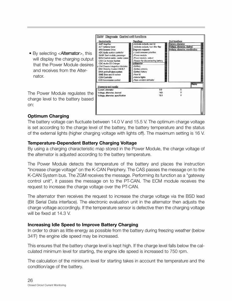
• By selecting <AAlltteerrnnaattoorr>, this will display the charging output that the Power Module desires and receives from the Alter- nator.
The Power Module regulates thecharge level to the battery basedon:
Optimum ChargingThe battery voltage can fluctuate between 14.0 V and 15.5 V. The optimum charge voltageis set according to the charge level of the battery, the battery temperature and the statusof the external lights (higher charging voltage with lights off). The maximum setting is 16 V.
Temperature-Dependent Battery Charging VoltageBy using a charging characteristic map stored in the Power Module, the charge voltage ofthe alternator is adjusted according to the battery temperature.
The Power Module detects the temperature of the battery and places the instruction"Increase charge voltage" on the K-CAN Periphery. The CAS passes the message on to theK-CAN System bus. The ZGM receives the message. Performing its function as a "gatewaycontrol unit", it passes the message on to the PT-CAN. The ECM module receives therequest to increase the charge voltage over the PT-CAN.
The alternator then receives the request to increase the charge voltage via the BSD lead(Bit Serial Data interface). The electronic evaluation unit in the alternator then adjusts thecharge voltage accordingly. If the temperature sensor is defective then the charging voltagewill be fixed at 14.3 V.
Increasing Idle Speed to Improve Battery ChargingIn order to drain as little energy as possible from the battery during freezing weather (below34oF) the engine idle speed may be increased.
This ensures that the battery charge level is kept high. If the charge level falls below the cal-culated minimum level for starting, the engine idle speed is increased to 750 rpm.
The calculation of the minimum level for starting takes in account the temperature and thecondition/age of the battery.

27Closed Circiut Current Monitoring
• By selecting <BBaatttteerryy>, this will display the battery “state of health” according to the Power Module’s calculation.
The relationship of charge vs: dis-charge can be seen here. This ishelpful for determining a sulfatedbattery.
Battery Charge Level DetectionThe Power Module knows what the charge level of the battery is at any time by calculatingthe battery current when the vehicle is being driven and measuring the discharge current.
When the vehicle is not in use, the charge level is re-calculated and updated by measuringthe closed circuit battery voltage. If the vehicle battery is replaced it must be registered withthe Power Module so that the stored values can be deleted and a new calculation started.
Central Battery Voltage NotificationThe Power Module continuously measures the battery voltage. This information is madeavailable to all other control units via the Bus link. This can be used, for example, to enablecontinuous running of the sliding/tilting sunroof regardless of battery voltage.
Central battery voltage notification eliminates the need for individual measurement of bat-tery voltage by each control module.
Data MemoryThe Power Module data memory stores electrical system activity (data) relevant to the vehi-cle. That information provides a status read-out of the battery load and life. The data mem-ory will be used in future to obtain a load profile of the battery in normal operation that willbe analyzed for Condition Based Service.
Battery Temperature SensorIn the event of a defective sensor, a short circuit or an implausible value, the substitute valueof 20 ºC is assumed. This corresponds to a fixed charge voltage of 14.3 V at the battery.
Battery capacity (SoC) is calculated using the substitute value.

28Closed Circiut Current Monitoring
• By selecting <BBaatttteerryy ssttaattiissttiicc>, this will display the time the bat-tery has spent in what “state of charge” according to the Power Module’s calculation.
The Power Module determinesthe battery state of charge (SoC)and the time in the SoC rangewhich is required for:
To ensure that the car is capable of starting, the charge level (SoC) of the battery is moni-tored when the vehicle is at rest.
The minimum battery SoC required to ensure that the car can be started again is a calcu-lated value.
The calculation takes into account the:
• Battery temperature measured over last few days
• Engine type
• Capacity of the battery fitted (110Ah for the 745i).
The SoC calculation is displayed as a percentage of battery capacity (A fully charged bat-tery is considered 80%).
If the charge level of the battery gets close to that calculated minimum level as a result ofthe operation of an auxiliary consumer, the Power Module instructs that circuit to switch off.
NNootteess::
29Closed Circiut Current Monitoring
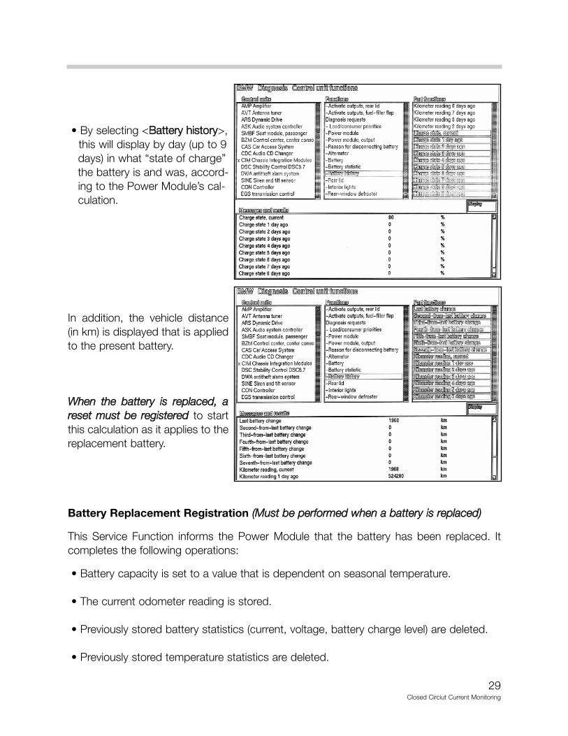
• By selecting <BBaatttteerryy hhiissttoorryy>, this will display by day (up to 9 days) in what “state of charge” the battery is and was, accord-ing to the Power Module’s cal-culation.
In addition, the vehicle distance(in km) is displayed that is appliedto the present battery.
WWhheenn tthhee bbaatttteerryy iiss rreeppllaacceedd,, aarreesseett mmuusstt bbee rreeggiisstteerreedd to startthis calculation as it applies to thereplacement battery.
Battery Replacement Registration ((MMuusstt bbee ppeerrffoorrmmeedd wwhheenn aa bbaatttteerryy iiss rreeppllaacceedd))
This Service Function informs the Power Module that the battery has been replaced. Itcompletes the following operations:
• Battery capacity is set to a value that is dependent on seasonal temperature.
• The current odometer reading is stored.
• Previously stored battery statistics (current, voltage, battery charge level) are deleted.
• Previously stored temperature statistics are deleted.

30Closed Circiut Current Monitoring
When the "RReeggiisstteerr bbaatttteerryy rreeppllaacceemmeenntt" is requested, the state of charge (SoC) of the bat-tery is not set to 80%, but to a value that is dependent on the seasonal temperature.
The seasonal temperature is an averaged time based value (over the last few days) for thebattery SoC that is required for a successful starting procedure.
The battery SoC value is set 28% above the SoC calculated from the seasonal tempera-ture. The following examples for the SoC after battery replacement are:
SSeeaassoonnaall TTeemmppeerraattuurree SSooCC VVaalluuee-25 ºC 98%-10 ºC 68%
0 ºC 66%10 ºC 63%20 ºC 61%30 ºC 58%
The SoC is maintained at these values until the ignition is switched “OFF” for > 2 hours. TheSoC is redetermined during the closed-circuit voltage measurement (conducted after 2hours) and then calculated based on the battery current.
NNoottee:: Central Locking, door changes (open/closed) and interior light status changes mustnot occur during this time because the timer will restart.
Procedure for Battery Replacement Registration
This procedure is found under:SSeerrvviiccee FFuunnccttiioonnss -- BBooddyy --VVoollttaaggee aanndd ccuurrrreenntt mmoonniittoorriinngg.
• Select <BBaatttteerryy>, <RReeggiisstteerr bbaatttteerryy rreeppllaacceemmeenntt> and <TTeesstt PPllaann>.
• Highlight the Test Module and press the green <AArrrrooww> to the right.

31Closed Circiut Current Monitoring
The screen prompts you toselect:
1. Display battery replacement(as described on page 29)
2. Register battery replacement
3. Terminate test module
Select #2. <RReeggiisstteerr bbaatttteerryyrreeppllaacceemmeenntt>, and press thegreen <AArrrrooww> to the right.
This screen prompts you to:
1. Enter battery replacement
2. Cancel
NNoottee:: The battery replacementwill be entered in the PowerModule in the next test step.
WWaarrnniinngg!! The entry cannot bereversed.
Again, this Service Function informs the Power Module that the battery has been replacedand completes the following operations:
• Battery capacity is set to a value that is dependent on seasonal temperature.
• The current odometer reading is stored.
• Previously stored battery statistics (current, voltage, battery charge level) are deleted.
• Previously stored temperature statistics are deleted.

32Closed Circiut Current Monitoring
Diagnostic Test Plans
Based on fault codes, additionaldiagnostic Test Plans can befound under: CCoommpplleettee VVeehhiiccllee --BBooddyy -- PPoowweerr SSuuppppllyy.
Test plans are available for:
1. Voltage/current monitoring
2. Battery
3. Alternator
When you select <VVoollttaaggee//ccuurrrreenntt mmoonniittoorriinngg>, the Test modules (based on the status dis-plays previously covered) available are:
CChhaarrggee ccoonnttrrooll - tests the Power Module’s management of battery charging.
LLooaadd--ssiiddee ppeeaakk ccoonnssuummppttiioonn rreedduuccttiioonn - tests the Power Module’s commands and rea- sons to activate the prioritized shutdown of electrical consumers.
EElleeccttrriiccaall ssyysstteemm ddiissccoonnnneeccttiioonn//EElleeccttrroonniicc bbaatttteerryy mmaasstteerr sswwiittcchh - tests the Power Module’s commands and reasons to reduce power consumption and disconnect exces-sive closed-circiut power consumers based on battery SoC and time.
LLooaadd ddeeaaccttiivvaattiioonn,, eelleeccttrroonniicc ffuussee - tests the Power Module’s commands and reasons to open the electronic master switch if a high short circuit current is detected.
BBaatttteerryy ccoonnddiittiioonn - tests the Power Module’s interpretation of the overall battery life.
CClloosseedd--cciirrccuuiitt ccuurrrreenntt ppeerrffoorrmmaannccee - tests closed-circuit current draws with additional Help Information (HI) documents showing examples of violations that prevent normal power down protocols and procedures to diagnose closed-circuit current faults.
NNootteess::

33Closed Circiut Current Monitoring
Review Questions
1. What information does the Power Module use to calculate the optimum charge voltage?
2. How would the driver of the vehicle know that the battery switch was in the “OFF” position?
3. What must be performed to the Power Module after replacing a battery?
4. What operations are a result of question 3?
5. During a normal Shut Down Protocol, what consumers are shut off after 60 minutes?
6. What 2 “visuals” indicate to you that the vehicle is continuing to enter sleep mode after the 16 minute period?
7. What should the final Closed-Circuit Current draw be on a “normal” vehicle? mA
8. What Bus circuit(s) are isolated when Fuse #15 is removed?
9. What fixed charge voltage would you expexct to measure if the Battery Temperature Sensor was defective? V
10. What is Special Tool #90 88 6 612 310 used for and what does it provide?