clnr heat pump case study - networkrevolution.co.uk
TRANSCRIPT

Copyright Northern Powergrid (Northeast) Limited, Northern Powergrid (Yorkshire) Plc, 2015
Case Study: Heat pump disruptive load
on a low-voltage overhead line
network
DOCUMENT NAME
CLNR-L260
AUTHORS
Chris Thompson, Preston Foster, Liam Wardley, Robert Stubbs, Richard Davis, Dean Naylor
Northern Powergrid
ISSUE DATE
20 January 2015

2
Copyright Northern Powergrid (Northeast) Limited, Northern Powergrid (Yorkshire) Plc, 2015
Contents
1. Executive Summary ................................................................................................................. 3
2. Heat Pump Concept................................................................................................................. 4
3. CLNR Heat Pump Trials ............................................................................................................ 5
4. Case Study of a Disruptive HP Load ......................................................................................... 8
5. Conclusions ............................................................................................................................ 16

3
Copyright Northern Powergrid (Northeast) Limited, Northern Powergrid (Yorkshire) Plc, 2015
1. Executive Summary
As part of the Customer-Led Network Revolution (CLNR) project, approximately 378 air source heat
pump (HP) customers were recruited and monitored across three different customer trials.
Of the 378 heat pumps, 344 were standard domestic capacity HP units and 34 were larger capacity HP
units capable of maintaining heating during either demand side response (DSR) calls or delayed
operation during time of use peak pricing, both via the means of a hot water thermal store.
This report is a case study that has taken information gathered as part of a voltage issue investigation
that Northern Powergrid undertook in response to a customer reporting a voltage complaint under
the Guaranteed Standards of Service – Regulation 15.1
The voltage complaint was received in November 2013 from a single customer who was suffering
voltage fluctuations (flicker), as a result of the operation of one of the 34 larger HP units that had been
installed in their neighbour’s adjacent property.
Both properties were electrically connected to the same part of a low-voltage (LV) rural overhead line
(OHL) network and were situated at the extremity of that network. The customers’ location
exacerbated the effects of the HP motor characteristics, highlighting the voltage issue, which
otherwise would have been difficult to detect. This is the only instance recorded on the CLNR project
where the HP operation caused such a voltage issue.
This report aims to inform both DNOs and HP installers of the potential effects that could be seen by
future installation of HPs on LV networks and in particular on rural LV OHL networks.
This report also considers the current connections application process for HP installations and makes
certain recommendations and lessons learned observations, including improving the communication
of the current HP connections process.
This report did not evaluate any other installations of HPs that are currently connected to the
Northern Powergrid network and has kept the identities of the customers involved anonymous.
Following the detailed investigation, site visits and consideration of the voltage monitoring test
results, the cause of the issue was identified to be from the high starting current of the HP due to a
faulty `soft start’ component.
Ultimately the complaint was resolved to the satisfaction of the complainant, when the defective HP
was replaced with a standard smaller capacity unit, following an instruction to the HP customer from
Northern Powergrid.
1 Guaranteed Standards of Service: www.northernpowergrid.com/asset/0/document/183.pdf

4
Copyright Northern Powergrid (Northeast) Limited, Northern Powergrid (Yorkshire) Plc, 2015
2. Heat Pump Concept
There are three different types of HPs; air sourced, water sourced and ground sourced. The CLNR
project only monitored air sourced heat pumps.
The HP is placed outside the property and takes in the external ambient air which it passes over an
evaporator to make a vapour. This is channelled into an electric compressor, which raises both the
pressure and temperature of the gas vapour. This heated vapour is then released at the heat
exchanger and this transferred heat can be used to either heat the building itself and / or store hot
water within a cylinder. The vapour is then condensed into a liquid and so the cycle starts again. The
concept is that the heat pump should use less electrical energy than conventional heating, as it is used
as means of transferring heat from outside to inside, rather than a device that generates heat. See
figure 1 below for an illustration.
Figure 1 – Heat Pump Cycle
The HP operates in two current consuming modes. It also has the ability to utilise an electric
immersion heater, which periodically switches on to provide more heat when the outside temperature
is too low. The heater considered within this case study uses 2.99kW of electrical power2.
During HP start-up, the compressor motor draws a high current. This high current drawn causes a
voltage drop, which in turn could have undesirable effects on other electrical equipment. One such
effect can be the flickering of lights in the home of neighbouring properties.
By fitting ‘soft start’ devices on the compressor the HP manufacturer expects to mitigate such effects.
The most common soft start device is the addition of a suitably sized capacitor to the compressor
motor. This will improve the power factor of the pump and increase the quality of the electrical
output.
2 Appendix A: HP test specification sheet

5
Copyright Northern Powergrid (Northeast) Limited, Northern Powergrid (Yorkshire) Plc, 2015
The heat pump installation considered within this case study was a large capacity HP unit that was
combined with a thermal store in a 300 litre water cylinder. The photos in figure 2 show an example of
a HP unit during installation. Detailed pre-trial modelling determined that this size of thermal store
should permit approximately 0.5 kW of load reduction during the 4pm to 8pm peak period, for a 3
bedroom semi-detached house in the North East of England. Once fully charged the thermal store
would be available to either receive a DSR signal which interrupts the HP electricity consumption for a
period, or alternatively, when combined with a ToU tariff could charge up off-peak, thus avoiding
electricity consumption during a portion of the peak priced ToU period. The 300 litre cylinder was able
to maintain satisfactory comfort levels for the customer for periods of up to one hour.
Figure 2 – Example Neura Heat Pump and Thermal Store during installation
3. CLNR Heat Pump Trials
The purpose of the CLNR HP trials was to fully understand the pattern of electrical power consumption
of the HP, in real-life customer scenarios through the use of monitoring equipment. This monitoring
data has been collected, analysed by Durham University and written outputs have been published on
the CLNR website.3 The CLNR project undertook three customer trials for HPs, monitored within
customers’ premises:
Enhanced monitoring of domestic HP customers (CLNR Test Cell 3)
Monitoring of domestic HP customers, on a ToU tariff combined with a thermal store (CLNR
Test Cell 12)
Monitoring of domestic HP customers, on a DSR direct control trial combined with a thermal
store (CLNR Test Cell 14)
3 http://www.networkrevolution.co.uk/resources/project-library/

6
Copyright Northern Powergrid (Northeast) Limited, Northern Powergrid (Yorkshire) Plc, 2015
The HP customer and their installation, considered within this case study, had been enrolled into the
last of the above CLNR trials for DSR direct control, Test Cell 14 (italicised above).
This CLNR trial was designed to test the:
Degree to which customers would accept direct control propositions to offer flexibility in their
electricity use
Degree to which customers who have formally accepted a direct control proposition actually
respond to DSR events when they are called
Technical concept of interruptible heating, during the 4pm to 8pm peak time in winter, whilst
maintaining comfort levels for customers (a technical first in the U.K.)
Technical concept of DNOs to enact an end-to-end direct control signal for domestic DSR,
initiated via a smart grid control system (Northern Powergrid’s GUS) to mitigate a network
constraint (a technical first in the U.K.). See figure 3.

7
Copyright Northern Powergrid (Northeast) Limited, Northern Powergrid (Yorkshire) Plc, 2015
Figure 3 Domestic DSR event initiated by the smart grid control system (GUS)
Control room
GUS
! Network monitored by GUS about to breach
acceptable headroom
GUS sends SMS to British Gas control room
GUS determines what the most cost-effective
actions are to remedy the issue
British Gas initiate DSR event on GreenCom
system
GreenCom system sends signal to
consumers’ heat pumps
GreenCom
system
Heat pumps respond to event

8
Copyright Northern Powergrid (Northeast) Limited, Northern Powergrid (Yorkshire) Plc, 2015
4. Case Study of a Disruptive HP Load
4.1 Background
This case study focuses on a HP with thermal store that was installed as part of the CLNR direct control
trials and was designed to monitor customers’ HP electrical power consumption, whole-house
electricity consumption and the customers’ ability to respond to direct control events.
The HP installations were not funded by the CLNR project, but by a Department of Energy and Climate
Change (DECC) grant awarded to British Gas (BG). Installation of the monitoring and communications
interfaces was funded by CLNR.
A summary of the manufacturers’ technical data for the HP under investigation is detailed in Table 1
and also in Appendices A and B of this report.
Title Value Unit
Heating Capacity (heat transferred into property) 10.65 kW
Power Consumption 2.99 kW
Coefficient of performance (capacity/consumption) 3.56 Ratio
Compressor peak starting current 130 A
Soft start max current (1/3 of peak) 43.3 A
Table 1 – Manufacturers’ (Neura Smart Energy Systems) HP Technical Data
Based on the HP unit specification being supplied with a soft start fitted, the HP installers did not
consider that an increase in electricity supply was required at the property. They also did not consider
that they needed to notify the DNO, either pre-or post-installation.
However, in the review process following the investigation, Northern Powergrid considers that for a
HP installation of this size it would have been good practice (although not mandatory) for the HP
installer to have contacted the DNO regarding the connection, in order to establish whether an
increase in electrical supply capacity would be required. The application process for a HP connection
is detailed within Appendix C.
In late November 2013, a verbal complaint was received via the Northern Powergrid customer contact
centre from a customer who was experiencing flickering lights, and who considered that their
neighbour’s new heating system may be the cause of the issue.
This complaint was investigated under the Guaranteed Standards of Service – Regulation 15
(previously known as EGS5), further detailed in Appendix D.

9
Copyright Northern Powergrid (Northeast) Limited, Northern Powergrid (Yorkshire) Plc, 2015
4.2 Investigation
The configuration of the network the complainant is connected to is as follows: A 20kV high-voltage
overhead line from a primary substation to a 100 kVA split phase, pole mounted transformer (installed
in the 1960’s) and then a low-voltage overhead line spanned across wooden poles to supply 11
customers split between agricultural and domestic properties. The LV overhead line had been recently
upgraded from a mixture of 0.05cu and 0.025cu open wire conductor, to 120 aerial bundled conductor
(ABC). The two customers in question were connected to the last pole, via a single phase direct 35mm2
service cable. See LV skeleton network diagram in figure 4.
Figure 4 –LV Skeleton of OHL network
Figure 5 –Photo of LV OHL network
Pole Mounted Substation
HP & complainant customers both
connected to last pole
Note: This drawing is out of date, 0.05 conductor has been
replaced with ABC
RHS building is split two semi-detached properties. HP property: LHS semi, Complainant: RHS semi.

10
Copyright Northern Powergrid (Northeast) Limited, Northern Powergrid (Yorkshire) Plc, 2015
In response to the complaint, a voltage recorder was installed in the complainant’s property for one
week, from 28 November to 5 December 2013. The result of this is shown in figure 6.
Figure 6 – Customer Premises: Flicker Nov/Dec 2013
In addition to the complainant’s property, the network was also monitored at the substation. The
results from the substation monitoring are shown in figure 7 which plots the flicker levels at the local
substation between 28 November and 8 December 2013.
Figure 7 – Pole Mounted substation: Flicker 28 November 8 December 2013
Pst Pst

11
Copyright Northern Powergrid (Northeast) Limited, Northern Powergrid (Yorkshire) Plc, 2015
In the standard IEC 6100-3-3 the observation and limiting values for Pst (short term flicker) and Plt
(long term flicker) are specified and are as follows:
Value Observation Interval Limiting Value
Pst 10 minutes 1.0
Plt 2 hours 0.65
The flicker levels recorded at the property were within limits, based on the monitoring intervals (10
minute average) as specified in the regulations.
The Total Harmonic Distortion (THD) at the affected customer and the substation was recorded at
2.1%, with the THD limit on an LV network being 5%. Short-term flicker (PST) data was also found to
be within the limits of 1.0. Similarly long-term flicker (PLT) was also within 0.65 acceptable limits.
The voltage recorder monitored the supply for 8 days at 10 minute sample rates, with the lowest
recorded voltage being less than 1% below 230V and the highest voltage being less than 8% above
230V (with acceptable limits being 230V -6% to +10%). See figure 8 below for the voltage data on the
peak day of 30 November 2013.
Figure 8 – Voltage data from 30 November 2013 (Peak Day)
Volts
Time
Highest voltage after 11pm

12
Copyright Northern Powergrid (Northeast) Limited, Northern Powergrid (Yorkshire) Plc, 2015
Despite the monitoring at both the substation and the customer’s property not showing the voltage
issues to be outside the Guaranteed Standard limits, the customer continued to experience issues
with flickering lights. Therefore an overhead line team was sent to check the low voltage overhead
line network for any loose service connections and to move the customer onto an alternate phase, in
an attempt to rectify the flickering issue. However, this did not resolve the problem.
The issue was passed onto the Northern Powergrid’s System Design Department in January 2014. The
two main options under consideration by the design team were either to balance the load of the 11
customers across the network, at an estimated cost of £4,000, (but which may not be successful), or
to reinforce the LV network by replacing the pole mounted substation and undergrounding the
overhead line with increased capacity 300 waveform cable. Whilst this would have undoubtedly
resolved the issue the cost was estimated at circa £26,000.
With no discernable reinforcement benefit apart from resolving the complaint and an unlikely
recovery from the HP customer the design team elected to monitor the effects of the HP directly by
installing a monitoring device within the HP property. Accordingly permission was sought from the HP
customer to install the monitoring equipment. All the tests were completed between 22 February and
1 March 2014. The analysed data is displayed in Figure 9 below.
Figure 9 –Flicker data from 22 February and 1 March 2014
13
Copyright Northern Powergrid (Northeast) Limited, Northern Powergrid (Yorkshire) Plc, 2015
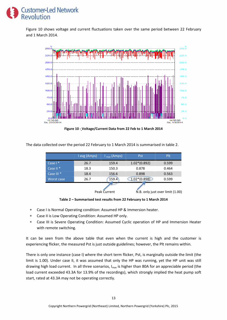
Figure 10 shows voltage and current fluctuations taken over the same period between 22 February
and 1 March 2014.
Figure 10 - Voltage/Current Data from 22 Feb to 1 March 2014
The data collected over the period 22 February to 1 March 2014 is summarised in table 2.
I avg (Amps) I max (Amps) Pst Plt
Case I * 26.7 159.4 1.02*(0.892) 0.599 Case II * 18.3 150.3 0.878 0.464 Case III * 18.4 156.6 0.898 0.563 Worst case 26.7 159.4 1.02*(0.898) 0.599
Peak Current N.B. only just over limit (1.00)
Table 2 – Summarised test results from 22 February to 1 March 2014
Case I is Normal Operating condition: Assumed HP & Immersion heater.
Case II is Low Operating Condition: Assumed HP only.
Case III is Severe Operating Condition: Assumed Cyclic operation of HP and Immersion Heater
with remote switching.
It can be seen from the above table that even when the current is high and the customer is
experiencing flicker, the measured Pst is just outside guidelines; however, the Plt remains within.
There is only one instance (case I) where the short term flicker, Pst, is marginally outside the limit (the
limit is 1.00). Under case II, it was assumed that only the HP was running, yet the HP unit was still
drawing high load current. In all three scenarios, Imax is higher than 80A for an appreciable period (the
load current exceeded 43.3A for 13.9% of the recordings), which strongly implied the heat pump soft
start, rated at 43.3A may not be operating correctly.

14
Copyright Northern Powergrid (Northeast) Limited, Northern Powergrid (Yorkshire) Plc, 2015
Before issuing a formal instruction to the HP customer to remove the disruptive equipment from the
network, a final visit was made to both properties on 7 March 2014. In attendance were the local
Repairs Manager, a Design Engineer, the CLNR Project Delivery Manager and the HP Installation
Technician, along with comprehensive test equipment. During the site visit different HP operating
modes were initiated and the effect within both properties were recorded and observed in order to
categorically prove the HP as the source of the disruption.
Three different HP modes were tested:
1. Standby Mode: Enough Hot Water to run heating system (Heat Pump off)
2. Full Mode: Water not hot enough (Heat Pump on)
3. Defrosting Mode: when outside temperature is below -30C, water is heated up utilising an
immersion heater (6kW) and circulates to defrost the HP outside. The immersion heater was a
separate unit which only operates during defrosting mode (in winter periods)
Forced testing of the HP was carried in the HP property and the current readings (Amps) were
recorded for starting and normal running conditions for both modes 1 and 2. The first two modes
were tested successfully, but the third ‘Defrosting mode’ would not initiate. The data is summarised in
table 3.
Starting Current (Amps) Normal Load Current (Amps)
(Ave.) (Peak) (Ave.) (Peak)
Standby Mode - _ 1.5 2.5
Full Mode 54 169.9 16.5 18.4
Showing excessive peak current
Table 3 – Summarised test results from 7 March 2014 site visit
During the full mode testing, flicker was observed three times at the complainant’s property at the
instant when the heat pump was initiated. The peak current was recorded to be 169.9A, being
approximately four times the rated 43.3A soft start current.
From the testing, it was proved that:
1. The HP was categorically causing the flicker at the complainant’s property
2. The HP was not working as per technical details provided by the manufacturer (i.e. soft start)
Even though the flicker was found to be within the prescribed limits (across a 10 minute average), it
was causing instantaneous flicker at the adjoining property, which was easily observed, even during
daylight hours. The issue had affected the complainant’s electrical quality of supply and the voltage
reductions were outside the limits allowable in the UK, as set by Engineering Recommendation P28.

15
Copyright Northern Powergrid (Northeast) Limited, Northern Powergrid (Yorkshire) Plc, 2015
4.3 Resolution
In the interest of other customers and in line with the Electricity Safety, Quality and Continuity
Regulations (ESQCR, 2002) the HP customer was instructed to remove the faulty HP within seven days
and not reconnect it, until the HP or its replacement could be proved to operate within the limits of
the connection supply that the customer had contracted with Northern Powergrid for.
The HP was electrically disconnected from the network by the HP installation technician, with the
consent of the HP owner, on the 10 March 2014.
The neighbouring property was no longer experiencing any voltage drop or flicker problems and the
complaint was closed.
On the 11 April 2014, permission to connect a smaller Mitsubishi HW-140-VHA HP unit requiring a
2.96kW electrical input and a 3kW immersion heater was given by Northern Powergrid’s Design team.
This unit came fitted with a 23Amp soft start.

16
Copyright Northern Powergrid (Northeast) Limited, Northern Powergrid (Yorkshire) Plc, 2015
5. Conclusions
From the review of this case study, the following conclusions can be drawn:
Customers and HP installers are currently installing heat pumps onto electricity distribution
networks without either advance or post-installation notice being given to the DNO. In this case
study example, there was no HP connection application made, nor any network study made, in
advance of the connection.
Where low-voltage electricity networks are either totally robust or robust at the point of HP
connection then the DNO is unlikely to become aware of individual HP installations regardless of
size. However in reality the HP installations may be utilising network capacity (headroom)
without paying for an appropriate increase in connection capacity.
The current HP connection process is: quite complicated; not well publicised; and is only best
practice, rather than mandatory. This means that many installers are either: unaware of the
current best practice process; or are ignoring it. The exception to this is most likely applications
made as multiple HP connections, via social housing providers or local housing authorities.
As HP installations have not yet taken off in the numbers that were previously anticipated, this
has not created power quality issues. However a sudden increase in the uptake of HP
installations could cause problems on the network.
Improved visibility of HP connections through a well communicated connections applications
process is therefore in the interest of DNOs. It is understood that DNOs are already liaising with
the Electricity Networks Association (ENA) to improve this.
Another consideration could be that the DNO should have the power to disconnect any low
carbon technology (LCT) equipment connected to the network, which haven’t followed the
correct application process.
It should be noted that in this case study example, had an application been made in advance to
Northern Powergrid System Design, based on the HP data specification, the application would
have been accepted and the HP connected.
However there would have been an advantage, when dealing with this particular complaint
(once the soft start had faulted) had the HP been registered at installation stage. The assessed
records of the HP, its specification and the network configuration would have been available to
those investigating the complaint. The level of fresh investigation undertaken during the period
that the complaint was live was costly in terms of time and frustration for the customer.
The voltage monitoring equipment installed at the complainant’s property was set to the
standard recording interval (10 minute average), however it was the use of higher resolution
equipment that identified and proved the source of the complaint. In the future, deployment of
higher resolution equipment may be beneficial in respect of suspected disruptive HP loads.

17
Copyright Northern Powergrid (Northeast) Limited, Northern Powergrid (Yorkshire) Plc, 2015
Appendix A

18
Copyright Northern Powergrid (Northeast) Limited, Northern Powergrid (Yorkshire) Plc, 2015
Appendix B

19
Copyright Northern Powergrid (Northeast) Limited, Northern Powergrid (Yorkshire) Plc, 2015
Appendix C
Application Process: Northern Powergrid process for applying for a connection to the
Network
Did the owner know his heat pump required increased capacity?
The information is available on the Northern Powergrid website:
“What if I already have a connection but need increased capacity, or additional phases?
The process for requesting additional capacity or additional phases is the same as the process for a
new connection. You will need to fill in an application form to provide us with information about the
location of your premises and details of the electrical load to be connected. You will also need to
provide us with a site location plan. Our application form guidance notes will help you if you need more
information. It is important that you fill in your application form in full, in order to ensure we can get
you your quotation in good time.”
Northern Powergrid has a policy guidance for heat pumps which requires every customer with heat
pump to
1. Notify Northern Powergrid.
2. Apply for connection irrespective of any size/phase.
The 2.99kW Heat pump installation was not notified to Northern Powergrid and there wasn’t any
assessment carried out which is mandatory. The HP owner may not have been made aware that the
following process is mandatory when increasing the capacity of your connection or fitting a heat
pump:
There are seven stages:
1. Apply for your connection.
2. We'll send you an offer of connection, valid for 90 days.
3. Return your signed acceptance and payment.
4. We'll contact you to arrange your job.
5. We'll send you a new meter Point Administration Number (MPAN) which you'll need to
give to your chosen supplier.*
6. We'll complete your work.
7. Your supplier will then arrange your meter installation.
* Not all connections will require a new MPAN

20
Copyright Northern Powergrid (Northeast) Limited, Northern Powergrid (Yorkshire) Plc, 2015
ENA Heat Pump Application
The Energy Networks Association (ENA) has made associated forms relevant to DNOs for HPs. These
consist of forms A, B or C. Depending on the equipment rating and whether it complies with standards
EN 61000-3-2 and EN 61000-3-3 will decide which form you are required to fill in. The forms will
provide key information for the DNO about the HP and therefore should be able to specify whether
the HP can be connected to the network or may require reinforcement work (at the cost of the
customer).
EN 61000-3-2 deals with the limitation of harmonic currents injected into the public supply system
whilst EN 61000-3-3 is concerned with the limitation of voltage fluctuations and flicker impressed on
the public low-voltage system.
Form A is used to connect a HP with equipment rated up to 75A per phase that complies with two
specific standards (EN 61000-3-2 and EN 61000-3-3).
Form B is used to connect a HP with equipment rated up to 75A per phase that doesn’t comply with
two specific standards (EN 61000-3-2 and EN 61000-3-3). Most HPs are applied under this form.
Form C is used to connect a HP with equipment rated over 75A per phase that doesn’t comply with
two specific standards (EN 61000-3-2 and EN 61000-3-3).
One of these forms should be submitted with the increased load application for the DNO. However
this is not made very clear on many DNO sites making the application process a difficult one.
G83
The G83 concerns only generation, not heat pumps or increased load. However, a document similar to
this would be useful for increased load and noise.
Associated Legislation
BS 7671 (The Wiring Regulations) states in section 132.16, Additions and alterations to an installation:
“No addition or alteration, temporary or permanent, shall be made to an existing installation, unless it
has been ascertained that the rating and the condition of any existing equipment, including that of the
distributor, will be adequate for the altered circumstances."
The Distribution Code DPC 5.2.1 states:
“Users shall contact the DNO in advance if it is proposed to make any significant change to the
connection, electric lines or electrical equipment, install or operate any generating equipment or do
anything else that could affect the DNO’s Distribution system or require alterations to the connection.”

21
Copyright Northern Powergrid (Northeast) Limited, Northern Powergrid (Yorkshire) Plc, 2015
The National Terms for Connection states:
"You must contact us in advance if you propose to make any significant change to the connection or to
the electric lines or electrical equipment at the premises, or if you propose to do anything else that
could affect our network or if you require alterations to the connection."
The Heat Pump Connection Process
With respect to heat pump installation we need to know:
1. What standards the installer is able to comply with
2. Does the installer comply with the HP standards stated on the Micro-generation Certificate
Scheme (MCS)
Installer Standards
– Micro-generation installation standard MIS 3005.
– Micro-generation Certification Planning Standards (MCS 020).
Product Standards
– ASHP compliant with MCS007 Product Certification Scheme Requirements - Heat Pumps.
– ASHP compliant with MCS010 Factory Production Control Requirements.
– ASHP compliance with MCS010 Testing Acceptance Criteria.
Limitations of heat pump without affecting the network
If the large heat pumps have a soft start mechanism installed, they take a reduced current upon start
up. This reduces the voltage fluctuations. Smaller heat pumps require less start up current so in some
cases, a soft start may not be required.
Trial period
There is currently no trial period or follow up inspection set by the manufacturer. Once the heat pump
is installed to the specifications and tested, it is expected to run normally. There are no tests or
inspections carried out by Northern Powergrid to check that heat pumps are not causing any
abnormalities on the network. This is only done when complaints are made about power quality.

22
Copyright Northern Powergrid (Northeast) Limited, Northern Powergrid (Yorkshire) Plc, 2015
Heat Pump Application/Connection Summary Flow Chart
Apply for an increased connection through DNO website
including the relevant ENA standard form.
Certain product data might be required from the manufacturer.
Seek a heat pump installer and product which is certified.
(Through MCS’s site)
Await offer of connection from DNO. This may include
reinforcement costs depending on the network.
Installer may begin works on heat pump
(After reinforcement works if necessary)
following the MCS’s installer standards.
DNO must be informed when the heat
pump has become online.
23
Copyright Northern Powergrid (Northeast) Limited, Northern Powergrid (Yorkshire) Plc, 2015
Appendix D
Investigation Process
An investigation of a voltage irregularity will be initiated in the event of a customer enquiry relating to
such an issue. If a customer reports a problem with the voltage of the electricity to their premises, a
member of staff will send the customer an explanation within 5 working days or offer to visit the
customer to investigate within 7 working days.
The Repairs & Restorations unit should arrange to conduct a site investigation at the customer’s
premises within the timescales set out in Electricity Guaranteed Standard 5 (EGS5) Voltage
Complaints, unless this is inconvenient to the customer. If the problem cannot be found on the initial
visit, but the site investigation shows that a voltage recorder should be fitted, then one shall be fitted
as soon as is practical. A voltage irregularity will be considered justified if the investigation identifies
that the supply voltage is outside the requirements of the ESQC Regulations 2002 or BSEN 50160 -
Voltage characteristics of electricity supplied by public distribution systems. If a voltage investigation
identifies a potential fault, this shall be investigated and rectified by the Repairs & Restoration unit.
All work undertaken by other business units to rectify a justified voltage irregularity will also be
completed within 6 months of the date justified, a requirement of EOS2. The completion date may
only be extended if all other feasible methods of rectifying the voltage problem have been explored
and discounted on reasonable grounds e.g. cost ineffective, creation of other network problems,
operational difficulties. There are standards and tolerances that the distribution network must
operate to. In line with these standards, Northern Powergrid is given powers to disconnect customers
who cause unwanted electrical noise on the network. This is shown in the ESQC Regulations 2002 in
Regulation 26:
‘Disconnection of supply, refusal to connect and resolution of disagreements 26.’
Where a connection to a distributor's network has been made, or is proposed, and the distributor is
not satisfied that the consumer's installation or other distributor's network or street electrical
fixture which is or would be connected to his network is or would be so constructed, installed,
protected and used or arranged for use so as to prevent, so far as is reasonably practicable, danger
or interference with his or any other distributor's network, or with the supply to any consumer's
installation or street electrical fixture, he may issue a notice in writing to the consumer or other
distributor or owner of the street electrical fixture (as the case may be) requiring remedial works to
be carried out within such reasonable period as may be specified in the notice.
If the remedial works specified in the notice by the distributor are not carried out by the end of the
period specified in the notice the distributor may disconnect or refuse to connect (as the case may
be) the supply to the consumer’s installation or other distributor’s network or street electrical
fixture, and in such an event the distributor shall by further notice in writing addressed to the
consumer or other distributor or owner of the street electrical fixture (as the case may be) set out
the reasons for the disconnection or refusal to connect.‘

24
Copyright Northern Powergrid (Northeast) Limited, Northern Powergrid (Yorkshire) Plc, 2015
Under this regulation, Northern Powergrid had the legal right to disconnect the owner of the heat
pump’s supply. A disconnection letter would be sent out to the owner stating the time period in which
they had to disconnect or fix the issue. If the resolve didn’t occur, Northern Powergrid may disconnect
their service cable past the given deadline.

25
Copyright Northern Powergrid (Northeast) Limited, Northern Powergrid (Yorkshire) Plc, 2015
For enquires about the project contact:
www.networkrevolution.co.uk