climate control system operation, · pdf fileclimate control system operation, diagnosis, and...
TRANSCRIPT

CLIMATE CONTROL SYSTEM OPERATION, DIAGNOSIS, AND REPAIR
Welcome to Climate Control System Operation, Diagnosis, and Repair, which is the
final training course in the Electrical training sequence. When you have completed
this course, you will know how to verify, diagnose, repair, and recheck problems
related to the climate control systems (refrigerant loop, heater, controls, and
automatic temperature control).
This course will teach you the diagnostic and repair skills you need to “fix it right the
first time” so you have satisfied customers instead of unhappy ones. Just like any
other automotive system, many Climate Control concerns are simple to solve, while
others are tricky to diagnose or require repairs to multiple components when one
component’s failure damages others.
Completing this course will also help prepare you for the ASE certification test for Air
Conditioning. Because ASE exams use domestic car terminology, you may want to
check out some ASE test preparation books from your local public library to finish
studying for the exam. Besides the obvious benefit that ASE certification shows your
expertise in auto repair, studying for the exams will improve your skills.

What is Climate Control? Climate Control refers to the systems in a vehicle that allow customers to adjust air
temperature, humidity, and direction. Although we usually think of climate control as
just a comfort feature, the defroster is a safety feature. Air conditioning also
improves the air quality, which may benefit people with certain health problems, by
dehumidifying and cleaning the air as it cools it.
All the components of the Climate Control system work together as a complete
system. Understanding the relationship between these components will help you
accurately verify and diagnose complaints. For example, when a customer selects
Defrost, the system opens the fresh air intake door, activates the heater core and
refrigerant loop, directs air over the evaporator and the heater core, and blows this
warm, dry air through the defroster ducts on the dashboard. If any one of these
components isn’t working properly, the customer will have concerns about poor
defroster performance. Similarly, a customer may have concerns with poor air
conditioner performance if the Sunload sensor has failed and the ATC is no longer
accounting for the heating caused by sunlight on the vehicle.
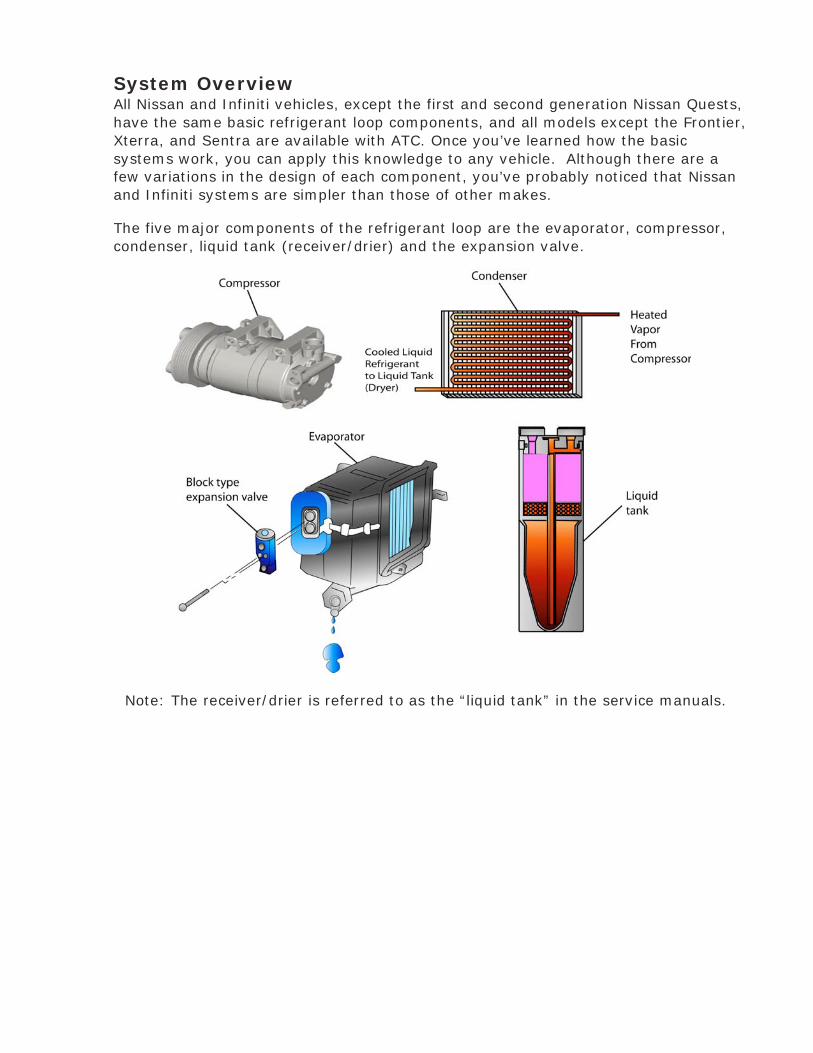
System Overview All Nissan and Infiniti vehicles, except the first and second generation Nissan Quests,
have the same basic refrigerant loop components, and all models except the Frontier,
Xterra, and Sentra are available with ATC. Once you’ve learned how the basic
systems work, you can apply this knowledge to any vehicle. Although there are a
few variations in the design of each component, you’ve probably noticed that Nissan
and Infiniti systems are simpler than those of other makes.
The five major components of the refrigerant loop are the evaporator, compressor,
condenser, liquid tank (receiver/drier) and the expansion valve.
Note: The receiver/drier is referred to as the “liquid tank” in the service manuals.

The basic operation of the refrigerant loop is quite simple: it moves heat from the
interior of the vehicle to the outside air.
• The compressor concentrates the heat in the refrigerant and propels it through
the system.
• The condenser transfers heat to the outside air.
• The receiver/drier filters the refrigerant and stores any excess liquid.
• The thermal expansion valve (TXV) sprays a mist of refrigerant into the
evaporator to start the loop again.
• Finally, the evaporator absorbs heat from inside the passenger compartment.
All these components are connected by rigid metal tubes and flexible hoses, and are
sealed with various seals and O-rings.
A variation of this basic system layout is found in the first and second generation
Nissan Quest, which has a fixed orifice tube (FOT) and an accumulator in the basic
system and a thermal expansion valve (TXV) in the optional rear air conditioner.
The engine compartment is a harsh environment due to vibration and heat, so it’s no
surprise the most common A/C problem is low refrigerant charge due to gradual
leakage.

Safety
Automotive air conditioners operate under high pressures and use refrigerants that
can be dangerous if improperly handled. Service and repairs should be performed
only by properly trained persons who understand refrigeration systems and their
operation. They must have access to specialized service tools and equipment, and
follow approved safety precautions. Additionally, any HVAC system refrigerant
recovery repairs require special licensing.
• Always wear eye protection when working on the refrigerant loop. If
refrigerant contacts your eye it may freeze, possibly causing an injury.
• Refrigerant can quickly cause frostbite. Avoid skin contact with refrigerant.
Always wear gloves when working with refrigerant.
• Work in a well ventilated area. Since refrigerant evaporates quickly, breathing
may become difficult due to lack of oxygen in poorly ventilated areas.
• Keep refrigerant away from open flame. Poisonous gas is produced when R-12
refrigerant burns.
• Never heat liquid refrigerant above 104°F as this may cause the container to
explode. Never apply direct flame to a refrigerant container.
• Keep refrigerant containers stored below 104°F
• Never release refrigerant directly into the atmosphere. It’s a federal law with
fines and imprisonment for anyone releasing refrigerant into the atmosphere.
Always use approved recovery, recycling and charging equipment.
• Never mix R-134a and R-12 or their refrigerant oils. Results will range from
poor A/C system performance to expensive component and equipment
damage.
• There are many different Federal, state, and local ordinances to control the use
of refrigerants and their release into the atmosphere. Make sure you comply
with these ordinances, including training and certification.

Refrigerant
Operation
The refrigerant in an air conditioning system absorbs, transports, and then releases
heat via the condenser. A good refrigerant must have a number of specific
characteristics. It must be:
• Compatible with a wide variety of materials such as brass, aluminum, copper,
steel, rubber and neoprene.
• Oil soluble, which allows it to circulate through the system with the oil.
• Non-poisonous and non-flammable.
Unfortunately, no single substance found in nature has all these characteristics.
Automotive refrigerants are man-made compounds developed especially for
automotive air conditioning systems.
Automotive refrigerant has changed over the years from ammonia gas, to R12
(Freon), to R134a. The characteristics of each gas and the purpose in the refrigerant
system have remained the same. The primary automotive refrigerant in general use
today is R134a. Although the name “Freon” is sometimes used to refer to any
automotive refrigerant, “Freon” is a registered trademark of DuPont.
R134a refrigerant is more environmentally friendly than R-12. Systems using R134a
have slightly higher pressures than an R12 system. In addition, R134a systems use a
different type of refrigerant oil which is specific to the type of compressor.
There is a distinct temperature-pressure relationship for R-134a refrigerant. As the
pressure increases, the boiling point rises. Refer to the chart on the following page
for these relationships.

Malfunctions
All automotive A/C systems eventually require service. A typical A/C system needs
recharging every three or four years, and contamination in the system (water,
incorrect oil, dirt, metal fragments, acids) can cause a wide variety of problems.
Much contamination can be prevented by keeping things clean while working on the
HVAC system. Make sure all valves and fittings are free of grease and dirt, and keep
the protective caps on components, lines, and hoses until you are ready to install
them. Always flush the system after failure of the compressor, receiver/drier, or
accumulator, as these components can introduce debris into the system when they
fail. Always double-check to make sure you are using the right type of oil for the
compressor.

Diagnosis
Cooling performance will be poor if the refrigerant is undercharged. To rule out other
causes of poor cooling performance, perform touch and feel diagnosis. If the
refrigerant charge is low, the thermal expansion valve and receiver/drier (or the fixed
orifice tube) will be warm or slightly cool to the touch. Both high-pressure and low-
pressure readings are low if refrigerant undercharge is the cause. Always check for
leaks and make any required repairs before recharging the system.
The compressor may be noisy if the refrigerant is overcharged. If the A/C alternates
between working well and not working, an excessive refrigerant charge may be
causing icing. If both high-pressure and low-pressure readings are high, and
particularly if splashing water on the condenser lowers the pressure, you will need to
remove enough refrigerant to meet the specification in the service manual.

The better you understand the basic principles of refrigeration, the easier it will be to
diagnose A/C problems. Refrigeration works by taking advantage of a few simple
physical principles:
1. Heat travels from high temperature to low temperature
areas.
2. Compressing a gas or vapor increases both its temperature
and pressure.
3. Removing heat from a gas or vapor makes it condense into a
liquid.
4. Raising the temperature of a liquid makes it evaporate into a
gas or vapor.
When refrigerant enters the evaporator as a mist, it vaporizes and
absorbs heat from the passenger compartment until it
leaves the evaporator as a slightly superheated vapor.
The vaporized refrigerant travels through the low-
pressure vapor lines to the compressor. The pistons in
the compressor pressurize the refrigerant and raise its
temperature.
This hot, high-pressure refrigerant vapor goes through
the high-pressure vapor lines to the condenser at the
front of the car. Because it is much hotter than the
outside air, air passing through the condenser absorbs
heat from the refrigerant. As the refrigerant loses heat,
it condenses to a liquid.
Next, the cool liquid refrigerant passes through the
liquid line to the receiver/drier to absorb any moisture
or impurities which could damage the system.
The refrigerant is still a warm liquid as it continues
through the liquid line to the thermal expansion valve
(TXV). When it reaches the TXV, the liquid refrigerant
is evaporator. During normal system operation, the
TXV allows enough liquid refrigerant into the
evaporator to keep it partially filled with vaporizing liquid refrigerant while the
system operates.
Notes: _____________________________________________
___________________________________________________

Refrigerant Loop Components
The refrigerant loop consists of a group of components which are connected by rigid
lines and flexible hoses and sealed with seals and O-rings. There are also two service
ports, one on the high pressure side and one on the low pressure side, to allow
access to the refrigerant for diagnosis and repair.
THERMAL EXPANSION VALVE (TXV) SYSTEM
In the standard thermal expansion valve TXV system, the major components are the
evaporator, compressor, compressor clutch, condenser, receiver/drier (liquid tank),
and block type thermal expansion valve.
Notes: _________________________________________________
_______________________________________________________
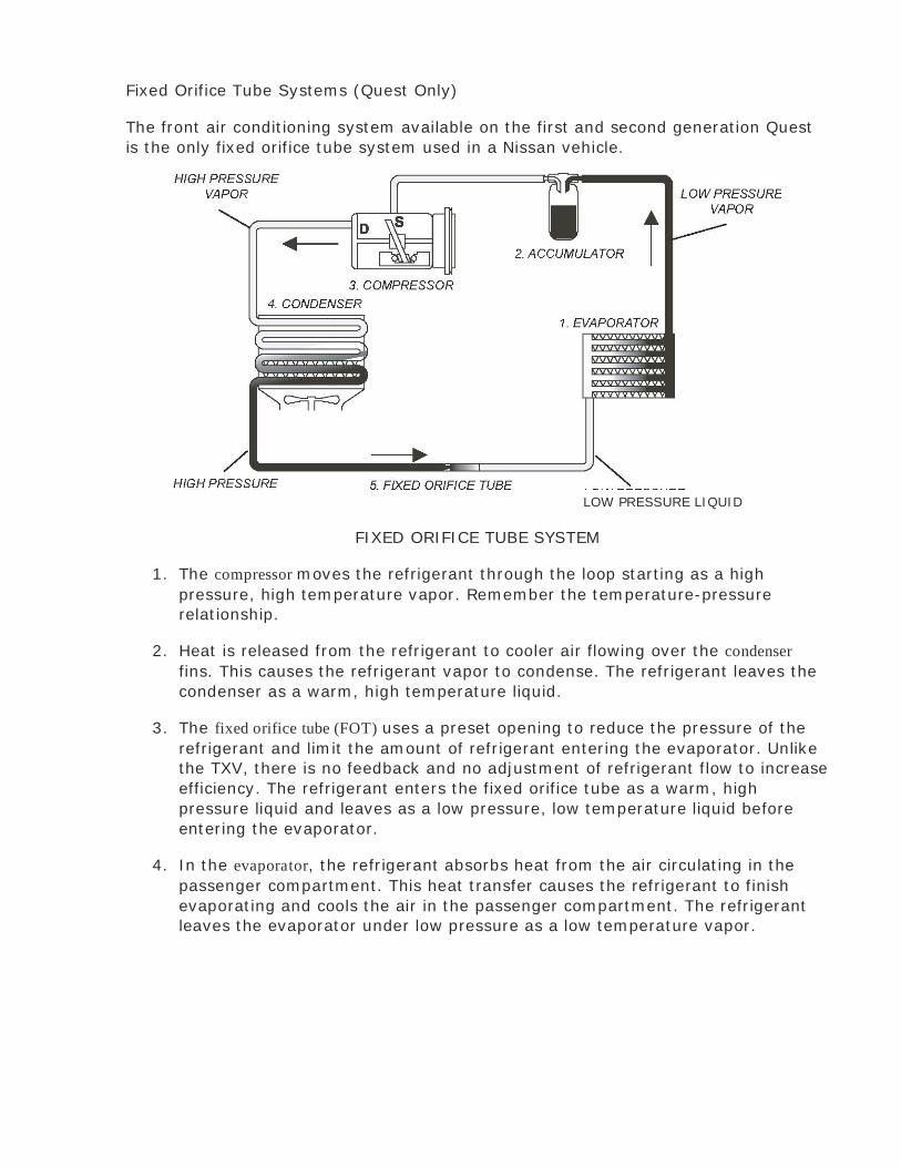
Fixed Orifice Tube Systems (Quest Only)
The front air conditioning system available on the first and second generation Quest
is the only fixed orifice tube system used in a Nissan vehicle.
LOW PRESSURE LIQUID
FIXED ORIFICE TUBE SYSTEM
1. The compressor moves the refrigerant through the loop starting as a high
pressure, high temperature vapor. Remember the temperature-pressure
relationship.
2. Heat is released from the refrigerant to cooler air flowing over the condenser
fins. This causes the refrigerant vapor to condense. The refrigerant leaves the
condenser as a warm, high temperature liquid.
3. The fixed orifice tube (FOT) uses a preset opening to reduce the pressure of the
refrigerant and limit the amount of refrigerant entering the evaporator. Unlike
the TXV, there is no feedback and no adjustment of refrigerant flow to increase
efficiency. The refrigerant enters the fixed orifice tube as a warm, high
pressure liquid and leaves as a low pressure, low temperature liquid before
entering the evaporator.
4. In the evaporator, the refrigerant absorbs heat from the air circulating in the
passenger compartment. This heat transfer causes the refrigerant to finish
evaporating and cools the air in the passenger compartment. The refrigerant
leaves the evaporator under low pressure as a low temperature vapor.

5. The refrigerant enters and leaves the accumulator as a low temperature, low
pressure vapor. The accumulator stores, filters and removes moisture from the
refrigerant. It also stores refrigerant oil and prevents liquid refrigerant from
entering the compressor. Notice that the accumulator is located on the low
pressure side of the refrigerant loop, while the receiver/drier is located on the
high pressure side.
FOT systems use an accumulator to dry, filter, and store refrigerant. It is placed
between the evaporator and the compressor to collect any liquid refrigerant in the
low pressure lines before it reaches the compressor.
Notes: _______________________________________________________
_____________________________________________________________
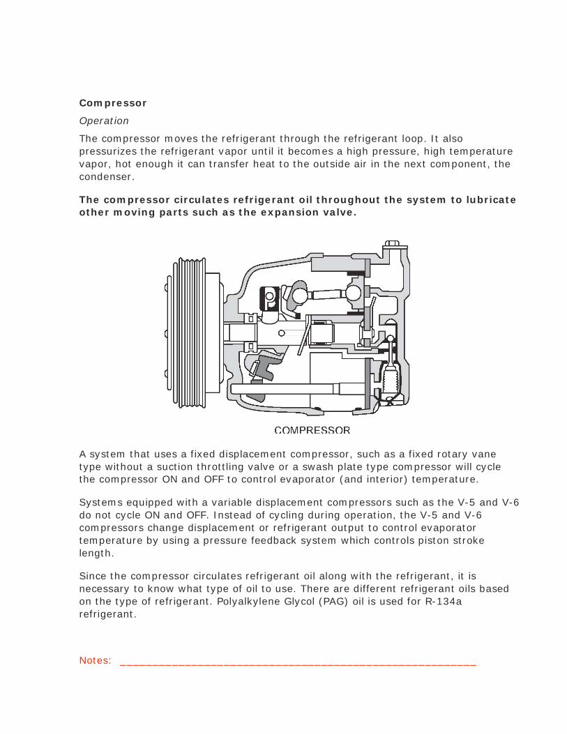
Compressor
Operation
The compressor moves the refrigerant through the refrigerant loop. It also
pressurizes the refrigerant vapor until it becomes a high pressure, high temperature
vapor, hot enough it can transfer heat to the outside air in the next component, the
condenser.
The compressor circulates refrigerant oil throughout the system to lubricate
other moving parts such as the expansion valve.
A system that uses a fixed displacement compressor, such as a fixed rotary vane
type without a suction throttling valve or a swash plate type compressor will cycle
the compressor ON and OFF to control evaporator (and interior) temperature.
Systems equipped with a variable displacement compressors such as the V-5 and V-6
do not cycle ON and OFF. Instead of cycling during operation, the V-5 and V-6
compressors change displacement or refrigerant output to control evaporator
temperature by using a pressure feedback system which controls piston stroke
length.
Since the compressor circulates refrigerant oil along with the refrigerant, it is
necessary to know what type of oil to use. There are different refrigerant oils based
on the type of refrigerant. Polyalkylene Glycol (PAG) oil is used for R-134a
refrigerant.
Notes: _______________________________________________________

Compressor Clutch
Operation
The compressor clutch is an electro-mechanical assembly that transfers mechanical
power from the engine to the compressor via a belt. The clutch engages the
compressor using an electromagnet in response to various sensor input signals. In
older fixed-displacement compressors, the clutch would stop and start the
compressor to control refrigerant flow. For swash-plate and variable-displacement
compressors, the clutch operates continuously.
COMPRESSOR CLUTCH
Malfunctions
Extreme operating conditions can cause the compressor clutch to fail. Compressor
clutch problems are often mistaken for compressor failure, as mentioned in the
discussion of the compressor.
Diagnosis
If the compressor is not operating, is operating poorly, or is operating noisily, check
the compressor clutch and belt for slippage. Remove the belt and turn the
compressor clutch by hand to check for noise and proper contact. (These parts may
be hot, so be careful.) Idler pulley bearings, when worn, also create a grinding noise
that could be misdiagnosed as a compressor clutch or compressor.
The clutch should always remain engaged for variable-displacement compressors,
and should engage and disengage as the system cycles on and off for fixed-
displacement and swash plate compressors. If the clutch does not engage, check the
electrical circuit and also check the clutch to see if it engages when supplied with
current.

On vehicles with an IPDM E/R, A quick test for compressor circuitry inspection is done
using the AUTO ACTIVE TEST. See the appropriate ESM PG section for information on
this test.
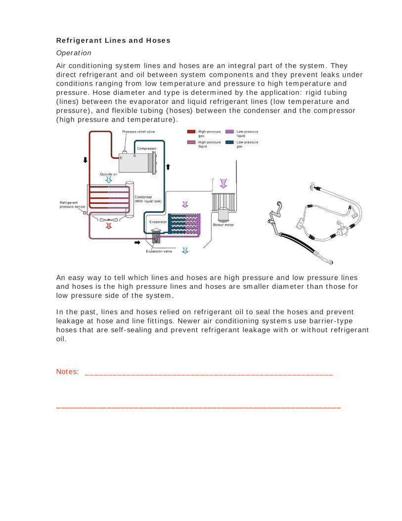
Refrigerant Lines and Hoses
Operation
Air conditioning system lines and hoses are an integral part of the system. They
direct refrigerant and oil between system components and they prevent leaks under
conditions ranging from low temperature and pressure to high temperature and
pressure. Hose diameter and type is determined by the application: rigid tubing
(lines) between the evaporator and liquid refrigerant lines (low temperature and
pressure), and flexible tubing (hoses) between the condenser and the compressor
(high pressure and temperature).
An easy way to tell which lines and hoses are high pressure and low pressure lines
and hoses is the high pressure lines and hoses are smaller diameter than those for
low pressure side of the system.
In the past, lines and hoses relied on refrigerant oil to seal the hoses and prevent
leakage at hose and line fittings. Newer air conditioning systems use barrier-type
hoses that are self-sealing and prevent refrigerant leakage with or without refrigerant
oil.
Notes: ______________________________________________________
______________________________________________________________

Condenser
Operation
The condenser operates very much like the radiator in a car, transferring heat to the
outside air by passing hot coolant through a collection of tubes and fins. Both the
condenser and the radiator are placed at the front of the vehicle and have fans to
ensure air flow even when the vehicle is stopped in traffic.
After refrigerant leaves the compressor, it enters the condenser as a high
temperature, high pressure vapor. As the refrigerant travels through the condenser it
is cooled by outside air flowing over the condenser fins. The refrigerant in the
condenser coils changes from a vapor to a liquid and leaves the condenser as a
warm, high pressure liquid. Because the refrigerant temperature is so high when it
enters the condenser, it is always hotter than the outside air, and can lose heat to
the air even on a hot day. However, just like the radiator, the condenser transfers
heat least effectively when you need it the most—when it’s very hot outside.
Three types of condenser are used in Nissan and Infiniti vehicles: serpentine flow,
parallel flow, and subcooling. You can identify the parallel flow condenser by the
refrigerant end tank and smaller, more closely spaced center section tubes, as
illustrated above.
The subcooling condenser has an extra cooling pass between the receiver/drier and
the lower third of the condenser for extra cooling power.

SUBCOOLING CONDENSER
Malfunctions
Condenser malfunctions are usually caused by internal restrictions, collision damage,
or obstructed air flow through the cooling fins. Noise or a vibration may result from
the condenser fins or lines touching the body due to deteriorating rubber mounts.
Diagnosis
If the condenser has internal restrictions, the air conditioner will be less efficient.
Touch and feel diagnosis will show the high side is hot and the low side is warm. High
side pressures will be high and low side pressures will be low. Collision damage can
crimp tubes without breaking them, causing a restriction rather than a leak.
Another cause of poor cooling performance is obstructed air flow, which can be
diagnosed by inspection. Leaves, plastic bags, dirt, and other trash can stick to the
front of the condenser and block air flow. Also check between the condenser and
radiator. Remember, at low speeds an inoperative condenser fan can cause the same
symptoms as obstructed air flow, so make sure the fan is operating. If there is an air
flow problem, touch and feel diagnosis will show that both inlet and outlet are hot, as
no heat is transferred out of the refrigerant. If you check with gauges, both high and
low side pressures will be higher than normal.
The condenser tubes are often overlooked as a source of refrigerant leakage and
should be checked thoroughly during a leak check procedure.
If the condenser seems to be making noise, check the rubber mounts for
deterioration and replace if needed.
Notes: _______________________________________________________
______________________________________________________________

Liquid Tank (Receiver/Drier)
Operation
The receiver/drier, sometimes referred to as the liquid tank, is a container with an
inlet and outlet at the top, and filters and a layer of desiccant inside. Older models
were cylindrical, but the new pointed base design makes it easier to recover small
amounts of refrigerant at the bottom.
RECEIVER/DRIER
The receiver/drier has three functions in the refrigerant loop:
• Stores refrigerant
• Removes moisture from the refrigerant using a desiccant
• Filters contaminants and debris from the refrigerant
Malfunctions
Receiver/drier malfunctions are often caused by contaminants clogging the filter. The
desiccant can only absorb a certain amount of water before it becomes saturated. In
either case, the receiver/drier will have to be replaced.
Notes: _____________________________________________________
____________________________________________________________

Diagnosis
If the receiver/dryer is restricted, discharge air will be warm. Touch and feel
diagnosis will show the inlet is warm and the outlet is cold. Frost may even appear on
the bottom of the receiver/drier. When a restriction is present, manifold gauge
readings will show the high side to be high and the low side to be low or at a vacuum
depending on the degree of restriction. This is because when refrigerant passes
through the restriction, it expands suddenly and loses heat, as if it were in an
thermal expansion valve.
If the receiver/drier is saturated with moisture, the outlet air will start out cold but
warm up in 5 to 10 minutes. This is caused by excessive moisture freezing in the
thermal expansion valve when the refrigerant temperature drops. If this happens,
touch and feel results will show a warm inlet and a cold (even frosted) thermal
expansion valve. Manifold gauge readings will be the same as those for a restricted
receiver/drier.
NOTE: At one time, it was standard practice to replace the receiver/drier whenever the
system was opened. In recent years, however, tests have shown this is no longer
necessary due to improved desiccant materials. You may have already seen the
service bulletin directing technicians to reuse the receiver/drier in most
circumstances.
The receiver/drier should only be replaced if:
• The compressor is seized
• Refrigerant oil contains metallic flakes
• Diagnosis indicates a major blockage
If you can’t document a specific reason to replace the receiver/drier, it will not
be covered on warranty claims. If you encounter a car with a third-party
extended warranty which requires receiver/drier replacement on all A/C work,
discuss the situation with your Service Manager.
,
NOTE: This is sometimes a difficult problem to understand, when there is a restriction in
the system like at the receiver/drier or at the expansion valve, the high side
pressure is lower than normal. If there is less refrigerant going to the compressor
from the restriction, the compressor has less to pump so the pressure is lower. If
the restriction were close to the compressor then the refrigerant would hydro-
lock and the pressure would be high. As long as there is room in the system to
store the refrigerant between the compressor and the restriction, then the high
side pressure is low.

HVAC Module and Intake Assembly
Operation
Most current HVAC systems consist of an HVAC module/unit assembly. The HVAC
module assembly contains the heater core, the door system, and evaporator core.
The blower housing is a separate unit. The cooling unit in the HVAC assembly
contains the evaporator core, the block type thermal expansion valve, and the door
system. The intake unit contains the intake door, thermo resistor or fan control
amplifier, and a blower.
A control system (controlled manually or electronically) directs air over the heater
core to raise the temperature, over the evaporator to lower the temperature and
humidity, and through the desired vents. In vehicles with manual controls, the
customer determines the airflow with a combination of settings, which directly control
heating, air conditioning, vent position, and fresh air intake. With automatic
temperature control (ATC), a central controller uses sensor input to control these
components and determine which route air takes through the HVAC module. It also
determines the most efficient fan speed.
HVAC UNIT BLOWER UNIT
Malfunctions
Each of the A/C components is discussed separately, and the door system is
discussed under ATC.
Notes: ______________________________________________________
_____________________________________________________________

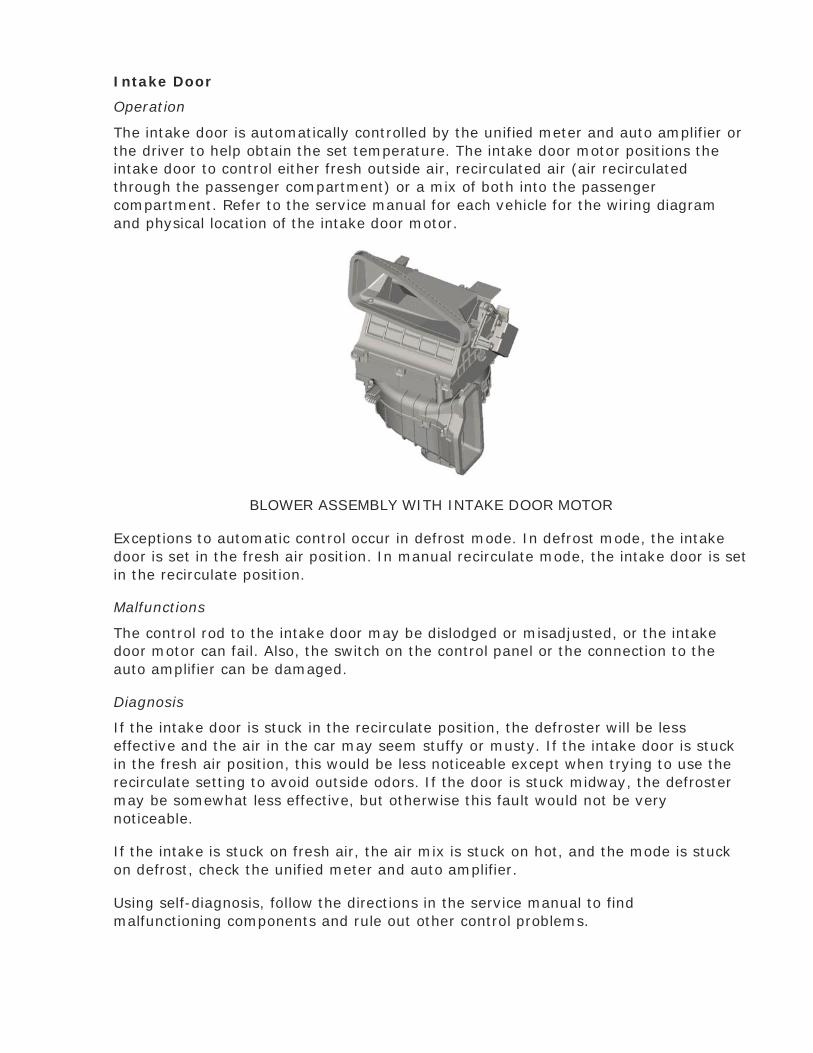
Intake Door
Operation
The intake door is automatically controlled by the unified meter and auto amplifier or
the driver to help obtain the set temperature. The intake door motor positions the
intake door to control either fresh outside air, recirculated air (air recirculated
through the passenger compartment) or a mix of both into the passenger
compartment. Refer to the service manual for each vehicle for the wiring diagram
and physical location of the intake door motor.
BLOWER ASSEMBLY WITH INTAKE DOOR MOTOR
Exceptions to automatic control occur in defrost mode. In defrost mode, the intake
door is set in the fresh air position. In manual recirculate mode, the intake door is set
in the recirculate position.
Malfunctions
The control rod to the intake door may be dislodged or misadjusted, or the intake
door motor can fail. Also, the switch on the control panel or the connection to the
auto amplifier can be damaged.
Diagnosis
If the intake door is stuck in the recirculate position, the defroster will be less
effective and the air in the car may seem stuffy or musty. If the intake door is stuck
in the fresh air position, this would be less noticeable except when trying to use the
recirculate setting to avoid outside odors. If the door is stuck midway, the defroster
may be somewhat less effective, but otherwise this fault would not be very
noticeable.
If the intake is stuck on fresh air, the air mix is stuck on hot, and the mode is stuck
on defrost, check the unified meter and auto amplifier.
Using self-diagnosis, follow the directions in the service manual to find
malfunctioning components and rule out other control problems.

Thermal Expansion Valve
Operation
All Nissan and Infiniti vehicles (except the Quest’s front air conditioner) use a thermal
expansion valve (TXV) to control refrigerant flow into the evaporator. The TXV uses a
controlled restriction to reduce refrigerant pressure and control the amount of
refrigerant flowing into the evaporator. Refrigerant enters the TXV as a warm, high
pressure liquid. When refrigerant leaves the TXV, it is a cold, low pressure liquid just
beginning to vaporize.
Block Type Expansion Valve Standard Expansion Valve
Refrigerant flow through the evaporator is moderated by feedback from a sensing
bulb at the evaporator outlet tube. This sealed sensing bulb contains a gas that
responds to the temperature of the refrigerant at the outlet of the evaporator and
changes the pressure on the diaphragm in the TXV.
As the temperature of the evaporator rises, the valve opens to release more
refrigerant. As the temperature falls, the valve closes to stop refrigerant flow and
prevent evaporator icing.
On standard expansion valves the sensing bulb must have good thermal contact with
the evaporator’s outlet tube, so it is usually wrapped to it with insulating foam.
All current Nissan and Infiniti vehicles use a Block Type Expansion Valve. This valve
functions exactly the same as the standard expansion valve with one exception, the
sensing bulb is contained in the valve housing.
It could be said that TXVs use a variable valve controlled by a feedback mechanism,
which allows them to change the refrigerant flow volume in response to varying
temperature conditions which increase efficiency.
Malfunctions
The TXV can stick open, stick closed or become restricted. The sensing bulb can also
malfunction, causing the TXV to stay closed. The opening of the valve is very small.
If the valve opening becomes restricted with contaminants, the TXV should be

replaced along with the receiver/drier.
Diagnosis
A TXV that is stuck closed or partially restricted will cause the discharge air to be cool
to warm. Not enough refrigerant is entering the evaporator, and it is cooling
inefficiently. The high side of the system will read high and the low side of the
system will read very low.
NOTE: When the TXV is closed all the way, refrigerant will still flow through the valve.
If there is debris in the valve then it could stop the flow of refrigerant
completely.
If the TXV is closed or completely restricted, you will not be able to hear the normal
hissing or spraying sound. The discharge air will be warmer, the high side pressure
will be higher than normal, and the low side may range from very low to a vacuum.
Because no refrigerant is flowing into the evaporator, evaporator temperature
remains high. A closed TXV may cause the compressor to run continually as it tries to
cool the passenger compartment. Variable-displacement compressors will remain at
maximum capacity. Fixed-displacement compressor systems will never cycle off.
Contamination by particles typically restricts or closes the valve. Also, if the sensing
bulb, its capillary tube, or the diaphragm has failed, the TXV will close. If
examination of the failed TXV shows contamination, flush the system and replace the
receiver/drier.
If the TXV is stuck open, outlet air will be slightly cool to warm. Touch and feel
diagnosis will find the tubes leading from the TXV are quite cold, and frost or ice may
be present. High side pressure will be slightly high and the low side will read high. A
stuck open TXV may also cause the evaporator to freeze up. If the evaporator
freezes, air flow from the outlet vents will be reduced. Ice formation can damage the
evaporator, so this is a serious condition. Typically, water or wax contamination or
mechanical failure will lock a TXV in the open position. If examination of the failed
TXV shows contamination, flush the system and replace the TXV, tube, and
receiver/drier (Liquid Tank).
NOTE: The ACR5 AC Service Center has the capabilities of flushing an AC system.
Refer to the owner’s manual for the proper procedure and adapters.
Notes: ________________________________________________________
_______________________________________________________________
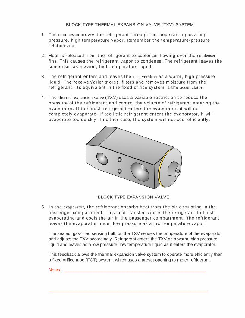
BLOCK TYPE THERMAL EXPANSION VALVE (TXV) SYSTEM
1. The compressor moves the refrigerant through the loop starting as a high
pressure, high temperature vapor. Remember the temperature-pressure
relationship.
2. Heat is released from the refrigerant to cooler air flowing over the condenser
fins. This causes the refrigerant vapor to condense. The refrigerant leaves the
condenser as a warm, high temperature liquid.
3. The refrigerant enters and leaves the receiver/drier as a warm, high pressure
liquid. The receiver/drier stores, filters and removes moisture from the
refrigerant. Its equivalent in the fixed orifice system is the accumulator.
4. The thermal expansion valve (TXV) uses a variable restriction to reduce the
pressure of the refrigerant and control the volume of refrigerant entering the
evaporator. If too much refrigerant enters the evaporator, it will not
completely evaporate. If too little refrigerant enters the evaporator, it will
evaporate too quickly. In either case, the system will not cool efficiently.
BLOCK TYPE EXPANSION VALVE
5. In the evaporator, the refrigerant absorbs heat from the air circulating in the
passenger compartment. This heat transfer causes the refrigerant to finish
evaporating and cools the air in the passenger compartment. The refrigerant
leaves the evaporator under low pressure as a low temperature vapor.
The sealed, gas-filled sensing bulb on the TXV senses the temperature of the evaporator
and adjusts the TXV accordingly. Refrigerant enters the TXV as a warm, high pressure
liquid and leaves as a low pressure, low temperature liquid as it enters the evaporator.
This feedback allows the thermal expansion valve system to operate more efficiently than
a fixed orifice tube (FOT) system, which uses a preset opening to meter refrigerant.
Notes: __________________________________________________________
_________________________________________________________________
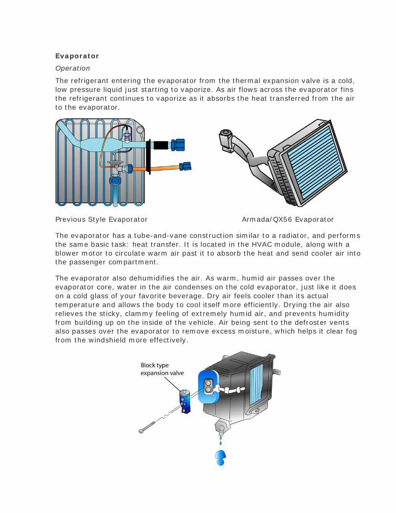
Evaporator
Operation
The refrigerant entering the evaporator from the thermal expansion valve is a cold,
low pressure liquid just starting to vaporize. As air flows across the evaporator fins
the refrigerant continues to vaporize as it absorbs the heat transferred from the air
to the evaporator.
Previous Style Evaporator Armada/QX56 Evaporator
The evaporator has a tube-and-vane construction similar to a radiator, and performs
the same basic task: heat transfer. It is located in the HVAC module, along with a
blower motor to circulate warm air past it to absorb the heat and send cooler air into
the passenger compartment.
The evaporator also dehumidifies the air. As warm, humid air passes over the
evaporator core, water in the air condenses on the cold evaporator, just like it does
on a cold glass of your favorite beverage. Dry air feels cooler than its actual
temperature and allows the body to cool itself more efficiently. Drying the air also
relieves the sticky, clammy feeling of extremely humid air, and prevents humidity
from building up on the inside of the vehicle. Air being sent to the defroster vents
also passes over the evaporator to remove excess moisture, which helps it clear fog
from the windshield more effectively.

Malfunctions
The evaporator is a very reliable component. Evaporator malfunctions are limited to
obstructed air flow or internal restrictions.
Air flow can be blocked by air flow through the In-Cabin Microfilter (if equipped)
leaves, paper, or other debris falling into the HVAC module through the air intake or
interior vents and being held against the evaporator by the air from the blower. Ice
forming on the outside of the evaporator fins (see “Diagnosis” below), may also block
air flow and reduce air conditioning performance.
On vehicles with the In-Cabin Microfilter, the entry of airborne dust and pollen
particles are filtered and restricted before they reach the evaporator coils.
If the Receiver/Drier fails, desiccant particles from the receiver/drier may lodge in
the evaporator core, although they are more likely to clog the TXV. Replacing a
damaged or failed receiver/drier or compressor without flushing the system may
allow debris to reach the evaporator. This is why it’s important to fix everything right
the first time, and think ahead to the consequences of a component failure.
Moisture removed from the air collects in the condenser pan and flows out a drain
tube. Occasionally, debris will clog the drain and water will accumulate in the HVAC
module. Customers typically are concerned about a stagnant odor or even water
dripping on their feet when it sloshes out of the condenser pan on sharp turns.
Except for this situation, musty odors from the evaporator are much less common
now due to water-repelling and mildew-resistant coatings on the condenser core and
pan.
Note: To protect the mildew-resistant coating, never clean an evaporator with anything stronger
than dishwashing detergent or other mild soap.
Diagnosis
• During touch and feel diagnosis (to be discussed later), the incoming line of a
properly operating evaporator is cool, the evaporator is just above freezing,
and the outgoing line is warm.

• Air flow through the discharge vents will decrease if air flow through the
evaporator is obstructed. Check for leaves or other foreign objects inside the
cooling unit.
• Evaporator icing can be a serious problem because the expansion of water as it
freezes can crack the evaporator. When the humidity inside the vehicle is
extremely high, water may condense on the evaporator and freeze if its
surface temperature is cold enough.
• Ice buildup on the evaporator fins blocks air flow and causes symptoms
noticed by the customer, such as poor or intermittent cooling. Except in
conditions of excessive humidity, this is typically caused by a defective thermal
expansion valve (TXV). Since it takes a while for ice to form, and it will often
melt after the evaporator is blocked long enough for the temperature to rise
above freezing, the customer may report that the air conditioner seems to
work intermittently. However, if a variable compressor fails so it is always in
its maximum stroke position, this will also cause the same symptoms.
• Any water in the refrigerant may freeze inside the evaporator. The symptoms
would be similar to the above, and would be cured by recycling the refrigerant
to remove the water and replacing the receiver/drier or accumulator (liquid
tank), as applicable.
• A restriction in the evaporator will cause slightly cool air at the discharge
vents. Touch and feel diagnosis will show the incoming line is cool, the
evaporator is not as cold as it should be, and the outgoing line is also cool, due
to poor heat transfer. High side pressures may be close to normal and low side
pressures will be lower than normal. If the evaporator is completely restricted,
you may get a vacuum reading on the low side manifold pressure gauge.
Notes: ____________________________________________________________
__________________________________________________________________