clifty creek station - us epa
TRANSCRIPT


Clifty Creek Station South Fly Ash Pond Dam 1 Date of Inspection: 6/11/09
FINAL REPORT
EXECUTIVE SUMMARY This Phase I Inspection/Evaluation Report details the results of a visual dam inspection of the Clifty Creek South Fly Ash Pond Dam (SFAP), located in Madison, Jefferson County, Indiana. The entrance to the plant is at Clifty Hollow Road, Route 56. The inspection was performed on June 11, 2009 by GZA GeoEnvironmental, Inc (GZA). For the purposes of this EPA-mandated inspection, the size of the impoundment will be based on U. S. Army Corps of Engineers (COE) criteria. The State of Indiana, Department of Natural Resources (INDNR) Dam Safety Regulations do not explicitly set size criteria for dam and levees under their jurisdiction. Based on an approximate embankment height of 70 feet the SFAP Dam would be classified as an Intermediate sized structure.
Under the EPA classification system the SFAP dam would also be considered as having Significant Hazard, due to possible environmental damage to the Ohio River if the embankment were to fail.
The dam was judged to be in SATISFACTORY condition in GZA’s opinion. The deficiencies at the dam that were noted during the current visual inspection include:
• Dense scrub vegetation covers the outfall to the 72-inch pipe at the toe of the dam. This vegetation should be removed and replaced with short grass cover to increase visual inspection in the future.
• Numerous minor scarps existing on the downstream face of the saddle dike embankment. These should continue to be monitored for movement.
• The floating oil skimmer at the spillway intake is in poor operating condition and should be
repaired or replaced to better prevent debris from penetrating the intakes. GZA recommends that the owner arrange for the following actions to be performed at the dam:
• IKEC/AEP should contact INDNR and formerly establish the magnitude of the spillway design flood for this dam. Previous studies allude to the possibility that the spillway does not have adequate capacity. Modification to the existing spillway and 72-inch outlet, including addition of a separate emergency spillway should, if necessary, be carried out based on the results of this detailed hydrologic and hydraulic analysis.
• A seepage and stability analysis should be conducted for the up and downstream slopes
based on the existing geotechnical information developed during the dam raising feasibility project and supplemented with more recent piezometric water level readings at the dam. This should include a seismic stability and liquefaction analysis of the upstream and downstream embankment slopes and foundation.
• It has been about 25 years since the last visual inspection of the interior of the 72-inch diameter RCP. A follow-up study, executed under confined space entry conditions, should be carried out to evaluate the current condition of pipe section alignment, joints, concrete surfaces, and support struts.

Clifty Creek Station South Fly Ash Pond Dam Date of Inspection: 6/11/09
FINAL REPORT
• Develop a formal, written Emergency Action Plan.
• Enact the proposed inspection program which is to include routine drive by inspections, quarterly checklist completion by IKEC engineering staff.
• Install a staff gage at the spillway decant intake in order to easily and regularly record pond level.
• Repair minor eroded areas on downstream slope near outfall headwall. • There are no major repairs recommended at this time. However, additional repairs and/or
modifications may be necessary and should be revisited based on the general stability and seismic analyses of the embankment, as well as establishment of the regulatory SDF and refined analysis of spillway capacity.
With respect to the Environmental Protection Agency’s (EPA’s) inquiry concerning whether any portion of the embankment was constructed upon coal ash slimes (known to GZA as TDF-5 and containing three specific questions), GZA provides the following response: Question 1 “Concerning the embankment foundation, was the embankment construction built over wet ash, slag or other unsuitable materials? – Although there was no specific record drawings, the embankments were constructed at the time of the plant construction and utilized the native clay soils from the area; i.e., wet ash and slag were not available and therefore we believe the embankment foundations were natural soil. This was confirmed in the south fly ash dam as they performed several borings after dam construction and boring logs indicated that the embankment was founded on natural/native soil. Also, communication (letters) from Arthur and Leo Casagrande, the embankment design consultants, indicated that the dams were to be constructed of native clay soils. Question 2 “Did the dam assessor meet with, or have documentation from, the design Engineer-of-Record concerning the foundation preparation?” – We did not meet with the design Engineer-of-Record. Documentation reviewed indicated that Arthur and Leo Casagrande provided recommendations for embankment construction and also visited the site during construction. Question 3 “From the site visit or from photographic documentation, was there evidence of prior releases, failures, or patchwork on the dikes?” Overall, no… issues that were encountered during construction of the south fly ash dam on the upstream slope were corrected at the time of construction. Routine maintenance has occurred but I don’t believe we would classify that as “prior releases, failures or patchwork…”
J:\170,000-179,999\170142\170142-00.JPG\Inspections\Clifty Creek, IN\Inspections\South Fly Ash runoff Pond\Draft Final Report\Executive Summary Draft Final.doc

Clifty Creek Station South Bottom Ash Pond Dam Date of Inspection: 6/10/09
FINAL REPORT
PREFACE
The assessment of the general condition of the dam is based upon available data and visual inspections. Detailed investigations and analyses involving topographic mapping, subsurface investigations, testing and detailed computational evaluations are beyond the scope of this report. In reviewing this report, it should be realized that the reported condition of the dam is based on observations of field conditions at the time of inspection, along with data available to the inspection team. In cases where an impoundment is lowered or drained prior to inspection, such action, while improving the stability and safety of the dam, removes the normal load on the structure and may obscure certain conditions, which might otherwise be detectable if inspected under the normal operating environment of the structure. It is critical to note that the condition of the dam depends on numerous and constantly changing internal and external conditions, and is evolutionary in nature. It would be incorrect to assume that the present condition of the dam will continue to represent the condition of the dam at some point in the future. Only through continued care and inspection can there be any chance that unsafe conditions be detected.
Prepared by: GZA GeoEnvironmental, Inc.
Walter Kosinski, P.E. Indiana License No.: 10201153 J:\170,000-179,999\170142\170142-00.JPG\Inspections\Clifty Creek, IN\Inspections\South Fly Ash runoff Pond\FinalFinal\Prefacestamp and sign.doc

CLIFTY CREEK STATION SOUTH FLY ASH POND DAM
JEFFERSON COUNTY, INDIANA
TABLE OF CONTENTS
1.0 DESCRIPTION OF PROJECT .......................................................................................... 1 1.1 General ................................................................................................................................... 1 1.1.1 Authority ................................................................................................................... 1 1.1.2 Purpose of Work ........................................................................................................ 1 1.1.3 Definitions ................................................................................................................. 1 1.2 Description of Project ............................................................................................................. 1 1.2.1 Location ..................................................................................................................... 1 1.2.2 Owner/Caretaker ....................................................................................................... 2 1.2.3 Purpose of the Dam ................................................................................................... 2 1.2.4 Description of the Dam and Appurtenances .............................................................. 2 1.2.5 Operations and Maintenance ..................................................................................... 5 1.2.6 Size Classification ..................................................................................................... 5 1.2.7 Hazard Potential Classification ................................................................................. 5 1.3 Pertinent Engineering Data .................................................................................................... 6 1.3.1 Drainage Area ........................................................................................................... 6 1.3.2 Reservoir ................................................................................................................... 6 1.3.3 Discharges at the Dam Site ....................................................................................... 6 1.3.4 General Elevations .................................................................................................... 6 1.3.5 Spillway Data ............................................................................................................ 7 1.3.6 Design and Construction Records and History ......................................................... 7 1.3.7 Operating Records ..................................................................................................... 8 1.3.8 Previous Inspection Reports ...................................................................................... 9 2.0 INSPECTION ....................................................................................................................... 9 2.1 Visual Inspection .................................................................................................................... 9 2.1.1 General Findings ..................................................................................................... 10 2.1.2 Upstream Slope ....................................................................................................... 10 2.1.3 Top of Dam ............................................................................................................. 10 2.1.4 Downstream Slope .................................................................................................. 10 2.1.5 Spillway/Outlet Structure ........................................................................................ 11 2.2 Caretaker Interview .............................................................................................................. 11 2.3 Operation and Maintenance Procedures ............................................................................... 12 2.4 Emergency Warning System ................................................................................................ 12 2.5 Hydrologic/Hydraulic Data .................................................................................................. 12 2.6 Structural and Seepage Stability ........................................................................................... 13 3.0 ASSESSMENTS AND RECOMMENDATIONS ............................................................ 14 3.1 Assessments ......................................................................................................................... 14 3.2 Studies and Analyses ............................................................................................................ 14 3.3 Recurrent Operation & Maintenance Recommendations ..................................................... 15 3.4 Repair Recommendations ..................................................................................................... 15 3.5 Remedial Modifications Recommendations ......................................................................... 15 3.6 Alternatives .......................................................................................................................... 15 4.0 ENGINEER’S CERTIFICATION.................................................................................... 15

CLIFTY CREEK STATION
SOUTH FLY ASH POND DAM JEFFERSON COUNTY, INDIANA
TABLE OF CONTENTS (Cont’d)
FIGURES Figure 1 Site Location Map Figure 2 Orthophoto Location Map Figure 3 Downstream Area Map Figure 4 Drainage Area Map Figure 5 Topographic Plan Figure 6 Photograph Location Plan APPENDICES Appendix A Limitations Appendix B Photographs Appendix C EPA & GZA Inspection Checklists Appendix D Definitions J:\01.0170142.00\Inspections\Clifty Creek, IN\Inspections\South Fly Ash Pond\TOC.doc

Clifty Creek Station South Fly Ash Pond Dam 1 Date of Inspection: 6/11/09
FINAL REPORT
1.0 DESCRIPTION OF PROJECT 1.1 General
1.1.1 Authority
The United States Environmental Protection Agency (EPA), through Lockheed Martin Corporation (LM), has retained GZA GeoEnvironmental, Inc. (GZA) to perform a visual inspection and develop a report of conditions for the Indiana-Kentucky Electric Corporation1 (IKEC, Owner) Clifty Creek Station, South Fly Ash Pond (SFAP) Dam in Jefferson County, Indiana. This inspection and report were performed in accordance with Task 3 of Lockheed Martin Competitive RFP for Assessment of Dam Safety of Coal Combustion Surface Impoundments, EAC-0381, dated March 17, 2009. The inspection generally conformed to the requirements of the Federal Guidelines for Dam Safety2, and this report is subject to the limitations contained in Appendix A and the Terms and Conditions of our Contract Agreement.
1.1.2 Purpose of Work The purpose of this investigation was to visually inspect and evaluate the present condition of the dam and appurtenant structures (the management unit) to identify conditions that may adversely affect their structural stability and functionality, to note the extent of any deterioration that may be observed, review the status of maintenance and needed repairs, and to evaluate the conformity with current design and construction standards of care.
The investigation was divided into four parts: 1) obtain and review available reports, investigations, and data previously submitted to the Owner pertaining to the dikes and appurtenant structures; 2) perform an on site review with the Owner of available design, inspection, and maintenance data and procedures for the management unit; 3) perform a visual inspection of the site; and 4) prepare and submit a final report presenting the evaluation of the structure, including recommendations and proposed remedial actions.
1.1.3 Definitions
To provide the reader with a better understanding of the report, definitions of commonly used terms associated with dams are provided in Appendix D. Many of these terms may be included in this report. The terms are presented under common categories associated with dams which include: 1) orientation; 2) dam components; 3) size classification; 4) hazard classification; 5) general; and 6) condition rating.
1.2 Description of Project
1.2.1 Location
The Clifty Creek Generating Plant is located about two miles northeast of Hanover, Indiana, and is part of Jefferson County. The entrance to the plant is at Clifty Hollow Road, Route 56.
1 Parent Company is American Electric Power (AEP) 2 FEMA/ICODS, April 2004: http://www.ferc.gov/industries/hydropower/safety/guidelines/fema-93.pdf

Clifty Creek Station South Fly Ash Pond Dam 2 Date of Inspection: 6/11/09
FINAL REPORT
The Clifty Creek Station’s SFAP Dam is located at latitude 38°43'48" North and
longitude - 85°26'10" West (WGS 84 datum), as determined from Google Earth. A site locus of the dam is shown in Figure 1. An aerial photograph of the dam is provided as Figure 2.
1.2.2 Owner/Caretaker
The dam is owned by the Indiana-Kentucky Electric Corporation, Piketon, Ohio.
Dam Owner Dam Caretaker Name Ohio Valley Electric Corp.
Indiana-Kentucky Electric Corp. Indiana-Kentucky Electric Corp.
Mailing Address P.O. Box 468, 3932 U.S. Rt. 23 P.O. Box 97 1335 Clifty Hollow Road
Town Piketon, Ohio 45661 Madison, Indiana 47250 Contact Donald T. Fulkerson Paul A de Lamerens Title Environmental Affairs Director Plant Environmental Superintendent E-Mail [email protected] Daytime Phone (740) 289-7254 (812) 265-8715 Emergency Phone 911 911
1.2.3 Purpose of the Dam
The SFAP Dam currently used to store runoff waters from the surrounding watershed as well as runoff from the facility’s existing dry fly ash land fill located about 1.2 miles northeast of the dam. Originally, the fly ash produced by the facility’s six generating units was sluiced to the pond in a slurry form. About 15 years ago, this operation practice was discontinued when a Type III landfill was constructed in the northern most region of the pond. The landfill was constructed over the hydraulically placed fly ash in the pond and they dry ash was placed in the landfill. Currently, as part of the flue gas desulfurization (FGD) project, the landfill is being redesigned to be permitted as a Type I landfill to accept synthetic gypsum along with the dry fly ash. The subgrade for this Type I landfill (located about 1 mile northeast of the dam) has been prepared and is anticipated to become operational in April 2010.
1.2.4 Description of the Dam and Appurtenances The Clifty Creek SFAP dam is located at the southern end of the pond about 700 feet
upgradient from the Ohio River. The dam is located at the far southwestern end of the Clifty Creek Plant. The dam and pond were created on what was Panther Creek near the stream’s outfall between miles 561 and 562 of the Ohio River. The earthen dam has a crest length of approximately 1,600 feet3 and is about 70 feet at its maximum section. The minimum crest elevation of the dam, taken from a 2008 topographic AutoCAD map made available by AEP, is about 502.9 MSL. However, crest elevations vary from 504.7 at the right abutment to about 505.1 MSL and 505.9 along the saddle dike and left abutment, respectively. The main portion of the dam’s downstream face has a constructed slope of about 2.7H:1V above elevation 474
3 As measured by GZA from 2008 topographic survey AutoCAD map provided by AEP.

Clifty Creek Station South Fly Ash Pond Dam 3 Date of Inspection: 6/11/09
FINAL REPORT
and about 3.3H:1V below elevation 474. The left portion of the embankment beyond the natural high ground, knows as the “saddle dike” has a downstream slope face of 2H:1V. The saddle dike is about 250 feet long and has a maximum height of approximately 15 feet. The upstream face of the main dam embankment has a slope of about 4.4H:1V according to the 2008 topographic survey. The original upstream face was designed with a 2.5H:1V slope, however, slope movement was reportedly observed during construction. The design engineers, Arthur and Leo Casagrande, recommended the placement of a 10-foot high, 100-foot long berm along the upstream portion of the dam to stabilize this movement. The berm reportedly corrected the situation and construction was completed in 1957. At the left portion of the upstream face, near the left abutment, fly ash fill was placed on some later date on a very shallow slope. A topographic plan is provide as Figure 5. An approximate 150 to 200 foot green space composed of grasses and large deciduous trees separates the toe of the dam from the right bank of the Ohio River.
Currently the SFAP has a normal operating pool of approximately 485 MSL and a
surface area of approximately 36 acres. The dam has a drainage area of about 693 acres4. Based on area/capacity curves included in the FMSM, 2008 dredge study, the pond has an approximate storage capacity of only 40 acre-feet at the normal operating pool (El 485 ± MSL) and maximum storage volume of about 800 acre-feet at the top of dam elevation 502.9 MSL.
Few original design drawings were made available to GZA as part of this dam
inspection. Most of what is reported on dam foundation and geotechnical characteristics was taken from the wealth of correspondence between the owner, American Gas & Electric Service Corporation (AEP), and the design engineers, Arthur and Leo Casagrande of Cambridge, Massachusetts. Other descriptive and historic information on the condition and functioning of the dam and outlet works was gleaned from various inspection reports and feasibility study summarized in the following sections of this report.
In general, foundation materials are reportedly characteristic of floodplain deposits
having intermixed layers of clay, sand and gravel overlying limestone bedrock. The near surface soils were reportedly primarily silts and/or “hard” clays and were underlain by “soft to medium stiff” clay. As indicated in a November 26, 1952 letter from design engineers Arthur and Leo Casagrande, “… the dikes will be constructed of relatively impervious material, upon a foundation of impervious material…”. Based on GZA’s review of available documentation, including subsurface boring data collected for a 1985 embankment raising feasibility study5, it appears the SFAP Dam was constructed of clay soils upon a foundation of natural silt or clay soils at the time of plant construction. As the embankment predates operation at this power facility, it is not likely that the embankment foundation was built over wet ash, boiler slag, or other unsuitable materials, in GZA’s opinion.
The main portion of the SFAP Dam consists of about 246,000 yd3 of primarily clay fill
that was mined from on-site borrow areas. Some sandy soils were mixed with the clay during borrow excavation. The more clayey, less permeable soils were reportedly placed on the
4 Fly Ash Pond Sediment Evaluation and Dredging Plans, Clifty Creek Coal Ash Landfill, Madison, Jefferson County, Indiana, Prepared by FMSM Engineers, for AEP, February 8, 2008. 5 “Flyash Dam Raising Feasibility Report”, prepared by Soils, Foundation and Hydro Section – Civil Engineering Division of AEP, dated January 31, 1985.

Clifty Creek Station South Fly Ash Pond Dam 4 Date of Inspection: 6/11/09
FINAL REPORT
upstream portion of the embankment. The smaller saddle dike consists of about 4,000 yd3 of compacted clayey fill. The embankments were constructed between 1956 and 1957.
In mid- to late-1956, significant movement in the fill was noticed at a point when the
dam was only about one foot from the design crest elevation. According to the discussion in the 1985 inspection report by Woodward-Clyde6, the movements occurred in the upstream direction (i.e. on the upstream face of the dam). As a consequence and at the recommendation of the design engineers, a 10-foot high, 100-foot long earthen berm was placed along a portion of the upstream toe of the main dam.
The spillway/outlet structure is a decant-type structure located on the side hill natural
ground near the right abutment of the dam. The sloped intake shaft has a rectangular cross section measuring 3 ft. x 6 ft. The inclined decant structure contains grated inlets located at about every 11 feet in elevation. Based on our review of original design drawings7, the decant structure appears to have been originally built with four separate intake openings. Based on the summary in the FMSM 2008 dredging study, the intake geometry is complicated and water can potentially enter at a lower elevation than 485.58 MSL. The intake structure has more recently been modified to accept water from the pond and interim elevation between 485 and 489 through the concrete coring of small diameter bore holes through the top of the incline box. An engineering sketch of the decant structure, developed by FMSM, indicates that the four main water intake elevations are: 485.87, 490.79, 496.74, and 501.61 MSL. Design drawings indicate that the intake can accept water at higher elevation approaching the top of the dam.
The design drawings indicate that the 72-inch outlet pipe is set on a 7.6-foot wide
concrete cradle with the pipe joints sealed with cement mortar and rubber gaskets. Three, 8-inch wide concrete water stops (i.e. anti-seep collar) were apparently constructed along the upstream half of the pipe at 50 foot in reinforced concrete pipe (RCP) with a series of 54 vertical steel struts, spaced on 4-foot centers within the center of the pipe. These struts are intended to add more reinforcing to the pipe due to the weight of embankment fill.
Water flows down the shaft of this sloped reinforced concrete structure and enters the
72-inch diameter RCP. The inlet invert of the 72-inch pipe is at elevation 432 MSL. This pipe is about 390 feet in length and outlet to a reinforced concrete head wall with training walls at the toe of the dam and to the remnants of Panther Creek. The head wall provides some energy dissipation of the outflow. The invert at the pipe outlet is 430 MSL and thus this pipe has an approximate slope of 0.005. From the head wall, Panther Creek extends about 700 feet before meeting the Ohio River.
More information on the construction and performance history of the dam is provided in sections 1.3.6, 1.3.8, and 2.5 of this report.
6“ Report on Dam Safety Inspection of Clify Creek Ash Ponds”, prepared by Woodward-Clyde Consultants, Inc., for AEP, Columbus, Ohio, dated February 1985. 7 IKEC Clifty Creek Plant, “Fly Ash Area – Lower Dam Drain Shaft Reinforcing Details”, Dwg. # 16-3173, dated July 2, 1956.

Clifty Creek Station South Fly Ash Pond Dam 5 Date of Inspection: 6/11/09
FINAL REPORT
1.2.5 Operations and Maintenance
The pond is used exclusively for stormwater management and is regulated by the Indiana Department of Natural Recourses under a NPDES discharge permit number IN0001759 (Outfall 002). The currently normal operating pool is at elevation 485 ± MSL. Based on our discussions with IKEC and AEP engineering staff, this current operating pool is about 10 feet less that the previous operating level. In fact, a 1981 AEP document indicates that, at that time, the pond was being decanted at elevation 499.8 MSL with a nominal water surface at elevation 500.8 MSL. The lower operation pool, which was started some 15 years ago, was necessary to lower the tailwater on the dry ash landfill and to accommodate leachate collection from the landfill. Also, as the SFAP was no longer sluicing ash, so storage volume and related settling does not need to be as high.
The embankments are typically mowed twice per year. Recently, AEP’s Geotechnical Engineering Division developed a revised, written inspection and maintenance program8 detailing routine duties and responsibilities of Plant personnel, Regional Engineering and Services pursuant to AEP’s Dam Inspection and Maintenance Program. The revised program for the SFAP Dam is to include: (a) routine “drive-by” inspections by Plant personnel looking for significant changes in conditions; (b) a formal “check-list type” inspection by Plant or Regional Engineering staff performed on a quarterly basis; (c) inspections performed under the direction of a registered professional engineer (P.E.) at a frequency determined by the dam’s risk classification (i.e., 2 year); and (d) non-routine inspections performed by plant personnel after unusual conditions such as heavy precipitation, seismic events, or other situations that could cause a change in the condition of the facility. According to Mr. Pedro Amaya, AEP Geotechnical Engineer, they are currently preparing an Emergency Action Plan (EAP) for the Clifty Creek Station facility.
1.2.6 Size Classification
For the purposed of this EPA-mandated inspection, the size of the impoundment will be based on U. S. Army Corps of Engineers (COE) criteria. The State of Indiana, Department of Natural Resources (INDNR) Dam Safety Regulations do not explicitly set size criteria for dam and levees under their jurisdiction. Based on an approximate embankment height of 70 feet the SFAP Dam would be classified as an Intermediate sized structure.
1.2.7 Hazard Potential Classification
Based on discussions with AEP engineering staff and IKEC personnel, the INDNR does currently inspect the SFAP Dam. INDNR dam safety staff last inspected the dam on July 9, 2008. The SFAP structure is noted as Panther Creek Dam on the INDNR Inspection Report and has a State Dam ID #39-12. Based on our review of the INDNR Dam Inspection Report, the SFAP Dam is classified as Significant Hazard.
Under the EPA classification system, as presented on page 2 of the EPA check list (Appendix C) and Definitions section (Appendix D), the SFAP dam would also be considered as
8 Circular Letter (#CL-M-CL-010B), “Dam and Dike Inspection and Maintenance Program”, Pedro J. Amaya (Author), revised May 19, 2009.

Clifty Creek Station South Fly Ash Pond Dam 6 Date of Inspection: 6/11/09
FINAL REPORT
having Significant Hazard, due to possible environmental damage to the Ohio River if the embankment were to fail.
1.3 Pertinent Engineering Data
1.3.1 Drainage Area
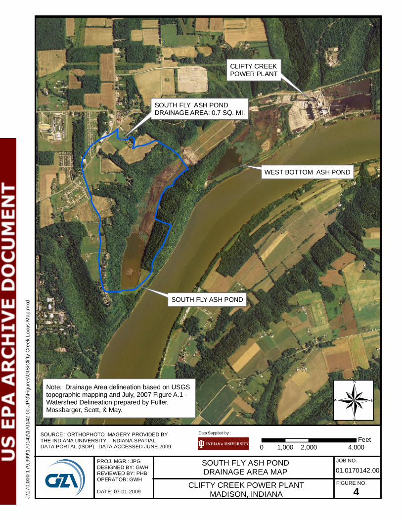
According to the 2008 Pond Sediment Evaluation and Dredging study, conducted by FMSM Engineers, that, prior to recent modifications, the watershed draining to the ash pond was about 693 acres (1.08 mi2). FMSM indicates that: “During the active and final conditions, the total drainage is approximately 443 acres”. The drainage area has gone under some modification recently due to the recent changes in plant operations. This has resulted in a decrease to the surrounding drainage area and runoff into the SFAP. As part of the ongoing flue gas desulfurization (FGD) project, a significant stormwater re-routing program has been recently completed which increases the drainage area to the adjacent West Bottom Ash Pond (WBAP). These modifications were performed due to the fly ash landfill being developed to the west of the site. The watershed is a mix of wooded and industrial areas of the power plant property. The approximate watershed boundaries for the SFAP dam are presented in Figure 4. Thus, it appears that the current contributing drainage to the SFAP is approximate 440 acres (0.7 mi2). The impoundment has a current normal operating surface area of approximately 36 acres at elevation 485 MSL.
1.3.2 Reservoir
The reservoir has undergone changes in size and storage capacity since original construction due to previous flyash deposition, creation of dry ash landfill, and lowering of the normal operational pool. Thus, the pond area is to the southwest, adjacent to the dam embankment. As previously mentioned, the normal pool has been lowered from about 495 to 485 MSL.
1.3.3 Discharges at the Dam Site
No records of flow were made available to GZA during our site visit. It is our understanding that plant environmental staff routinely measure and record pond levels, from which discharge could be inferred as needed.
1.3.4 General Elevations (feet – MSL)
Elevations are taken from design drawings, reports, and recent topographic survey
provided by AEP. Elevations are based upon the USGS topographic map MSL datum. A. Top of Dam (minimum) 502.9.0± B. Normal Pool 485 ±
C. Upstream Water at Time of Inspection 485.3± E. Downstream Tail Water at Time of Inspection 432 ± (at end of pipe)

Clifty Creek Station South Fly Ash Pond Dam 7 Date of Inspection: 6/11/09
FINAL REPORT
1.3.5 Spillway Data
A. Type Slanted concrete drop inlet/decant with multiple openings B. Effective Weir Length Typical opening: 2.5 ft. x 1.9 ft ± C. Opening typically set at 485 ± ft D. Outlet Conduit 72-inch RCP E. Upstream Outlet Invert 432 ft. ± (72-in. RCP) F. Downstream Outlet Invert 430 ft. ± (72-in. RCP) 1.3.6 1.3.6 Design and Construction Records and History The dam was designed by Arthur and Leo Casagrande of Cambridge, Massachusetts in
the early to mid-1950s. The Casagrande’s were also retained during the construction phase and reportedly made a number of visits to the site as the embankment and appurtenances were being built. Only limited design drawings exist for the SFAP Dam; however, numerous technical memoranda and letters between the design engineer and owner (AEP) during the design and construction of the plant and other structures on the site do exist and were made available to GZA during our inspection. It should be noted that Arthur Casagrande was considered one of the leading geotechnical engineers in the world at the time, particularly in the subject of earthen dam structures.
Construction occurred between the late spring of 1956 through 1957. As previously
mentioned, the embankment is primarily composed of on-site borrow materials consistent primarily of clays, intermixed with varying amounts of sand and silty sand. Excessive movement of the embankment fill on the upstream face occurred near the completion of the dam construction, sometime between August and October 1956. As a consequence, several defects were observed at that time, including: (a) cracking of the crest; (b) cracking and opening of many joints in the 72-inch concrete pipe; and (c) some upstream movement of the lower end of the sloping concrete decant chute. In October of 1956, a 100 foot long x 10 foot high earthen berm was placed along a portion of the upstream toe (i.e. heel) of the main dam embankment. In a letter from A. Casagrande to E. Kammer (AEPs Chief of Design), dated October 4, 1956, a summary was presented dealing with the condition of the 72-inch RCP subsequent to the embankment movement. Dr. Casagrande reported that: “The earth movement caused the upstream half of the pipe to be stretched in such a way that many of the joints opened up. In addition, one section of pipe developed a vertical crack along which the pipe parted longitudinally about 6-inches. All joints which have opened up, as well as the large vertical crack, can readily be repaired.” It is assumed that repairs to the interior of the 72-inch RCP were made at about that time.
In the early 1980’s, a feasibility of raising the dam about 30 feet was undertaken by
AEP’s Civil Engineering Division. The study included the execution of a subsurface exploration program during the summer of 1984; field and laboratory testing of soils for their strength and compressibility characteristics; field measurements of water level and hydraulic conductivity at and below the dam; and stability analysis for the proposed raising of the SFAP dam crest from approximately 505 MSL to 535 MSL.

Clifty Creek Station South Fly Ash Pond Dam 8 Date of Inspection: 6/11/09
FINAL REPORT
The results of the feasibility study indicated several technical issues that prohibited the raising of the SFAP dam crest. Of particular concern were the results of the exploration program and stability analysis, which identified a soft, natural clay zone below the main dam having relatively low strength. The slope stability analysis resulted in factors of safety very close to 1.0 (approximately 1.03 to 1.05) for several critical dam cross sections for the increased crest elevation scenario. As a result, and due to the surficial topographical limitations, the downstream slope could not be flattened sufficiently to improve the dam stability and therefore the project was discontinued.
The subsurface exploration program performed during the feasibility study also clearly demonstrated several additional pieces of information. First, although construction records were not available, the subsurface explorations indentified the embankment fill as medium stiff to stiff silty and sandy clay, which was consistent with the proposed fill material. The water level analysis and in-situ permeability testing also demonstrated that the flyash had helped seal the upstream embankment face such that the water levels measured in the field were within natural subgrade soils and/or limestone. As a result, seepage through the dam was not considered an issue.
With respect to whether GZA’s dam assessors met with, or have documentation from, the design Engineer-of-Record concerning the foundation preparation, we offer the following in addition to that described above: GZA did not meet with the design Engineer-of-Record. Documentation reviewed indicated that Arthur and Leo Casagrande provided recommendations for embankment construction and also visited the site during construction
Concerning the embankment foundation, and whether the embankment built over wet ash, slag, or other unsuitable materials, GZA offers the following in addition to that described above: Although there was no specific record drawings, the embankments were constructed at the time of the plant construction and utilized the native clay soils from the area; i.e., wet ash and slag were not available and therefore we believe the embankment foundations were natural soil. This was confirmed in the south fly ash dam as they performed several borings after dam construction and boring logs indicated that the embankment was founded on natural/native soil. Also, communication (letters) from Arthur and Leo Casagrande, the embankment design consultants, indicated that the dams were to be constructed of native clay soils.
1.3.7 Operating Records
No formal operating records dealing with pond open water levels, were made available
to GZA during the dam inspection. However, there is an extensive network of piezomters at the SFAP Dam. These piezometers were installed as part of a raising feasibility study done in 1984-85. Information provided to us indicates that the piezometric water levels at these monitoring locations are typically read and recorded on quarterly basis.

Clifty Creek Station South Fly Ash Pond Dam 9 Date of Inspection: 6/11/09
FINAL REPORT
1.3.8 Previous Inspection Reports Visual inspections of the SFAP Dam are typically done by AEP engineering staff on a
yearly basis. At GZA’s request, AEP provided the latest report9 prepared in October 2008. An independent consultant inspection report from 1985 (Woodward-Clyde) and a more recent independent inspection report10 was prepared in May 2009 by Stantec Consulting Services, Inc. of Cincinnati, OH was also reviewed by GZA. Both inspections concluded that the overall condition of the embankment forming the SFAP Dam was in satisfactory condition. The exterior slope was in stable condition and no significant sloughing or seepage areas were apparent. Key recommendations from Stantec included:
• Begin monitoring the slip on the southeastern exterior slope [saddle dike] as
part of the quarterly inspections; • Investigate animal burrows along the exterior slope of the dam along the right
abutment. In 1985, AEP commissioned Woodward-Clyde to conduct a visual inspection11 of the interior portions of the 72-inch RCP outlet from the decant spillway. Based on this evaluation, Woodward-Clyde made the following key conclusions and recommendations:
• The pipe was found to be in good structural condition; • About 27 of the 48 joints inspected were found to be intact, with 90 to 100
percent of the joint filled with cement mortar. The misalignment and/or separation of some of the joint do not appear serious or of recent origin;
• Where joint filler was missing or misaligned (up to 2-inches), the joints were essentially dry;
• The reduction in effective pipe diameter, either as a result of the buildup of hardened flyash or the presence of construction debris and struts was of a more immediate concern;
• Existing hydraulic calculations should be updated to consider the effect of the obstructions;
• Removal of the obstructions may be required if the analyses indicate that the pipe has insufficient discharge capacity to pass the design storm.
2.0 INSPECTION 2.1 Visual Inspection The South Fly Ash Pond Dam at the Clifty Creek Station was inspected on June 11, 2009 by Walter Kosinski, P.E. and Peter H. Baril of GZA GeoEnvironmental Inc. At the time of the inspection, the weather was partly cloudy with temperatures in the in the high 70°’s Fahrenheit. Photographs to document the current conditions of the dam were taken during the inspection and
9 2008 Dam & Dike Inspection Report, East Bottom Ash Pond, Fly Ash Pond, West Bottom Ash Pond – Clifty Creek Plant, Madison, IN, prepared by Geotechnical Engineering AEP Services Corp., Columbus, Ohio, Inspection Date: Sept. 9, 2008, Approval Date: Nov. 3, 2008; QA/QC Document # GERS-08-014. 10 2009 Dam and Dike Inspection Report – Clifty Creek Power Plant, Madison, IN, prepared by Stantec for AEP, May 14, 2009 (inspection date: April 2, 2009). 11 Inspection of 72-inch Reinforced Concrete Discharge Pipe, Clifty Creek Power Plant, by Woodward-Clyde Consultants, Inc., prepared for AEP, December 17, 1985.

Clifty Creek Station South Fly Ash Pond Dam 10 Date of Inspection: 6/11/09
FINAL REPORT
are included in Appendix B. The water elevation in the impoundment was approximately 484.2 feet MSL, based on the location of the pond level on the sloped decant chute structure. Underwater areas were not inspected, including the inside of the 72-inch diameter outfall culvert, as this level of investigation was beyond of GZA’s scope of services. A copy of the EPA and separate GZA inspection checklists are included in Appendix C. With respect to our visual inspection there was no evidence of prior releases, failures, or patchwork observed by GZA. However, based on discussions/information gathered during our inspection work, we understand that issues which were encountered during construction of the south fly ash dam on the upstream slope were corrected at the time of construction. Routine maintenance has occurred since that time, but said maintenance, in GZA’s opinion, would not be classified as “prior releases, failures or patchwork..”
2.1.1 General Findings
In general, the South Fly Ash Pond Dam was found to be in SATISFACTORY condition. The specific concerns are identified in more detail in the sections below. A topographic rendering of the dam in plan and location and orientation of photographs are contained in Figures 5 and 6, respectively.
2.1.2 Upstream Slope (Photos 1, 2, 3, 4 and 5) The upstream slope was built at slope of about 4.4H:1V. In general, the slope is in good condition and consists of cover of maintained short grass. Intermittently, the slope above the normal pool and top of dam was protected with small riprap. At the base of the slope, at the water line, the area contains 8 to 12-inch tall wetland grasses. No unusual movement or sloughing was observed. The slope at the saddle dike was much shallower sloped and irregular due to past filling. This area too was grassed, well maintained, and recently mowed.
2.1.3 Top of Dam (Photos 6, and 7) The top of the dam runs in a curvilinear shape following the natural high ground. It primarily consists of an asphalt paved surface serving as an access road for facility staff. The road was originally a public way. As reported earlier in this report, the crest’s vertical alignment is fairly level, ranging from a low point elevation of 502.9 MSL about 300 feet east of the right abutment to elevation 504.7 and 505.92 MSL at the right and left abutments, respectively. The condition of the paved surface is fair to poor, with numerous lateral and longitudinal cracking. Encroachment of weeds and grass through many of the cracks, especially at the edges of the pavement is occurring. The guard rail on the majority of the crest is in poor condition.
2.1.4 Downstream Slope (Photos 8 through 17) The downstream slope of the dam is generally in good condition. The face is consistently covered with grass, which was recently mowed. The main dam is set at a slope of about 2.7H:1V above elevation 474 and about 3.3H:1V below elevation 474, and appears to be stable. No unusual movement was observed. Surficial soils were somewhat saturated, but this was attributed to the heavy rainfall experienced in the days leading up to the field inspection. Surface runoff could be seen moving down the slope in several areas of the slope in the vicinity of the maximum section. Some shallow surficial erosion was noted near the base of the slope

Clifty Creek Station South Fly Ash Pond Dam 11 Date of Inspection: 6/11/09
FINAL REPORT
(see Photo 11). The condition of the downstream slope at the saddle dike was found to be in similar condition. However, the surface did exhibit many shallow scarps owning to its 2:1 slope. Most scarps were healed and were fully vegetated. Based on discussions with AEP and IKEC personnel, this shallow movement in the saddle dike slope is a long-time condition. Previous filling at the toe had been done in an attempt to buttress the slope and mitigate the further sloughing of the slope. This was an issue noted in previous inspection reports and should continued to be monitored for further movement. A large stand of deciduous trees exists beyond the toe between the dam and the Ohio River. In general, these trees do not pose an issue with respect to interfering with routine visual inspections. 2.1.5 Spillway/Outlet Structure (Photos 18 through 23)
The water level in the pond is controlled by defined openings in the top of the reinforced concrete chute portion of the decant spillway. Access to the spillway was via the right abutment down a stairway which parallels the chute. The structure was in fair to good condition. Walkway grating, above the second intake, was in good condition. Some woody debris had accumulated on the grated inlets and newly cored opening (see Photo 19). More well established vegetation could be seen growing and partially blocking the third intake (see Photo 21). This debris and vegetation was subsequently removed by IKEC staff while we were on the site. IKEC staff demonstrated how the solid cover hatches over the intakes are removed. The ease to which one could open these hatches during a large storm event is questionable. The floating debris boom, located at the spillway intake, appeared to be in poor condition and partially submerged, allowing floatable objects to reach the intakes.
The end of the 72-inch RCP and associated head wall appeared to be in good conditions.
Access to the structure was made difficult due to the dense overgrowth of the herbaceous vegetation on top of and the sides of the structure (see Photo 22). The tailwater extended about to the springline of the pipe. Flow was adequately dissipated prior to discharge to Panther Creek, with no erosion or other unusual movement observed.
No other auxiliary spillway or low level outlet exists at the SFAP Dam.
2.2 Caretaker Interview Maintenance of the dam is the responsibility of the IKEC operating plant personnel. Regular maintenance activity at the dam consists of visiting the spillway to take water quality samples. Mowing is performed about two times per year by a subcontractor. Based on recently developed O&M program, an IKEC representative is to conduct regular drive-by inspections and complete a check list inspection on a quarterly schedule. AEP Geotechnical Engineering staff performs an annual inspection of the dam and appurtenant structures.

Clifty Creek Station South Fly Ash Pond Dam 12 Date of Inspection: 6/11/09
FINAL REPORT
2.3 Operation and Maintenance Procedures See sections 1.2.5 and 2.2 above.
2.4 Emergency Warning System Currently, there is no written Emergency Action Plan (EAP) developed for the dam. According to AEP Geotechnical Engineering staff, an EAP is under development. 2.5 Hydrologic/Hydraulic Data GZA did not perform an assessment of the hydraulics and hydrology for the dam as this was beyond our scope of services. However, we did review several reports that did comment on spillway capacity of the decant structure. The dredge study conducted by FMSM included a flood routing study using a design flood having a 25-year return period. This is not considered relevant for assessing spillway capacity for dam safety purposes. A 1981 Hydrologic and Hydraulic Evaluation report prepared by AEP as part of an INDNR floodway construction permit provided some information about spillway capacity. AEP indicated that the Emergency Spillway Design Flood is over 100 years but less than the ½ Probable Maximum Flood (PMF). The design storm used by AEP was estimated at 8-inches of rainfall. Discharge capacity at the spillway design flood (SDF) is 68 cfs and has a resultant maximum water surface elevation of 502.25 MSL, with minimum freeboard of 2.75 feet. AEP indicate that there is an additional 300 ac-ft of storage capacity between elevation 502.25 MSL and the top of the dam. They also state that the dam was built to a final settled elevation of 505 MSL. AEP concluded that the total project discharge capability of the spillway exceeds the peak inflow of the performance standard SDF. A more telling comment on spillway capacity was found in the 1985 Woodward-Clyde (W-C) inspection report. In discussing flood routing, they state:
“In an internal AEP memorandum (from M.J. McLatchy to P.H. Anderson )dated 12 March 1984, it was indicated that the existing spillway will not meet the hydraulic demands generated by the probable maximum flood(PMF) at the site. The 72-inch diameter discharge pipe (with an inside area reduced by bracing) would have insufficient capacity to discharge the flow, even if the capacity of the intake structure were to be increased. The implication of the memorandum is that, until the storage capacity of the reservoir is increased by raising the dam, the discharge capacity of the present spillway is inadequate”.
GZA shares the concern related to spillway capacity under SDF conditions at the SFAP Dam. Obviously, increased storage capacity due to raising the dam crest did not occur due to geotechnical stability concerns. The normal pond level has been significantly reduced in the intervening years since the publishing of the 1985 W-C inspection report. This has increased the attenuation capacity of the pond and spillway outlet to pass flood flows. However, whether the pond and dam, in its current operation configuration can safely pass the SDF is not known at this

Clifty Creek Station South Fly Ash Pond Dam 13 Date of Inspection: 6/11/09
FINAL REPORT
time. It is likely that the SDF for this structure, based on INDNR guidelines12, is the ½ PMF. Thus, it is recommended that the dam be reassessed for current operating conditions under the regulatory SDF. Modification to the existing spillway and 72-inch outlet, including addition of a separate emergency spillway should be carried out, if necessary, based on the results of this detailed hydrologic and hydraulic analysis. It should be noted that an AEP boring plan drawing #CE-CCBP-2-85, dated July 1976, shows a sketch of a “proposed emergency spillway”, located just beyond the left abutment (i.e. immediately east of the saddle dike). It is unknown whether the owner had seriously contemplated the addition of an emergency spillway at some time in the past. 2.6 Structural and Seepage Stability GZA did not identify specific structural or seepage design analysis within the documentation reviewed. Reference however was made in the November 27, 1952 letter from Arthur and Leo Casagrande to Mr. E.A. Kammer, Chief Design Engineer for AEP, stating:
“Design of the Dikes. Since the dikes will be constructed of relatively impervious material, upon a foundation of impervious material, and since the length of period that the dikes will be exposed to high river stages is limited, no special control measures against seepage through and beneath the dikes are required. However, in view of the soft clay foundation and the great difference in elevation between the crest of the dikes and the adjacent deepest excavation, special attention will have to be paid to the question of stability of the dikes, including their foundations. It is noted that in some of the storage areas there is a difference in elevation of 40 to 50 ft between the crest of the dikes and the inside excavation level, with an inside slope of only 1 on 1.75. There is no doubt in my mind that such a steep slope would overstress the soft foundation clay and cause foundation failure of such high dikes.”
The comments made my Arthur and Leo Casagrande in 1952 were apparently incorporated into the design of the SFAP Dam as evidenced by the 1984-1985 feasibility study and the flattened upstream and downstream slopes. As previously stated, the feasibility study subsurface exploration program also confirmed the presence of silty and sandy clay compacted fill within the embankment structure and the fact that the SFAP Dam was founded on natural silty clay soils or limestone. Although the stability analysis was performed on a proposed embankment with increased crest elevation, these data could be used to re-evaluate the current stability of the existing dam since data is available. Additionally, the subsurface program also confirmed some consolidation of the underlying natural clays due to the existing embankment height; however, the data also shows that further consolidation (and increased strength) will likely occur with time. Similarly, the piezometric data collected quarterly since 2004 shows similar conditions to those observed during the time of the feasibility study; i.e., flyash has generally sealed the upstream face of the dam and water levels appear to be controlled within the natural underlying clay soils and limestone foundation. As such, it appears seepage analysis may be performed to confirm the interpreted design features using these data.
12 Indiana Dept. of Natural Resources, Division of Water, “General Guidelines for New Dams and Improvements to Existing Dams in Indiana”, 2001 Edition, Section 4 – Hydrology and Hydraulics (p. 4.3).

Clifty Creek Station South Fly Ash Pond Dam 14 Date of Inspection: 6/11/09
FINAL REPORT
3.0 ASSESSMENTS AND RECOMMENDATIONS 3.1 Assessments In general, the overall condition of Clifty Creek Station South Fly Ash Pond Dam is judged to be SATISFACTORY. The dam was found to have the following deficiencies:
1. Dense scrub vegetation covers the outfall to the 72-inch pipe at the toe of the dam. This vegetation should be removed and replaced with short grass cover to increase visual inspection in the future.
2. Numerous minor scarps existing on the downstream face of the saddle dike embankment. These should continue to be monitored for movement.
3. The floating debris boom at the spillway intake is in poor operating condition and
should be repaired or replaced to better prevent debris from penetrating the intakes. The following recommendations and remedial measures generally describe the recommended approach to address current deficiencies at the dam. Prior to undertaking recommended maintenance, repairs, or remedial measures, the applicability of environmental permits needs to be determined for activities that may occur within resource areas under the jurisdiction of the appropriate regulatory agencies.
3.2 Studies and Analyses
1. Based on our review of existing information, it does not appear that a recent hydrologic and hydraulic analysis has been conducted, under current engineering standards, to adequately assess spillway capacity under design flood conditions. IKEC/AEP should contact INDNR and formerly establish the magnitude of the spillway design flood for this dam. Previous studies allude to the possibility that the spillway does not have adequate capacity. Modification to the existing spillway and 72-inch outlet, including addition of a separate emergency spillway should, if necessary, be carried out based on the results of this detailed hydrologic and hydraulic analysis.
2. A seepage and stability analysis should be conducted for the up and downstream slopes
based on the existing geotechnical information developed during the dam raising feasibility project and supplemented with more recent piezometric water level readings at the dam. This should include a seismic stability and liquefaction analysis of the upstream and downstream embankment slopes and foundation.
3. It has been about 25 years since the last visual inspection of the interior of the 72-inch
diameter RCP. A follow-up study, executed under confined space entry conditions, should be carried out to evaluate the current condition of pipe section alignment, joints, concrete surfaces, and support struts.


FIGURES

PROJ. MGR.: JPGDESIGNED BY: GWHREVIEWED BY: PHBOPERATOR: GWH
DATE: 07-01-2009
J:\1
70,0
00-1
79,9
99\1
7014
2\17
0142
-00.
JPG
\Fig
ures
\GIS
\Clif
ty C
reek
Loc
us M
ap.m
xd
SOUTH FLY ASH PONDUSGS QUAD LOCATION MAP
CLIFTY CREEK POWER PLANTMADISON, INDIANA
JOB NO.
FIGURE NO.
SOURCE : SCANNED USGS TOPOGRAPHIC QUADRANGLESSCANNED BY THE INDIANA UNIVERSITY - INDIANA SPACIALDATA PORTAL (ISDP). DATA ACCESSED JUNE 2009.
Data Supplied by :
101.0170142.00
SOUTH FLY ASH POND
0 2,000 4,0001,000Feet
®
CLIFTY CREEK POWER PLANT

PROJ. MGR.: JPGDESIGNED BY: GWHREVIEWED BY: PHBOPERATOR: GWH
DATE: 07-01-2009
J:\1
70,0
00-1
79,9
99\1
7014
2\17
0142
-00.
JPG
\Fig
ures
\GIS
\Clif
ty C
reek
Loc
us M
ap.m
xd
SOUTH FLY ASH PONDORTHOPHOTO LOCATION MAP
CLIFTY CREEK POWER PLANTMADISON, INDIANA
JOB NO.
FIGURE NO.
Data Supplied by :
201.0170142.00
SOUTH FLY ASH POND
0 2,000 4,0001,000Feet
®
CLIFTY CREEK POWER PLANT
SOURCE : ORTHOPHOTO IMAGERY PROVIDED BYTHE INDIANA UNIVERSITY - INDIANA SPATIALDATA PORTAL (ISDP). DATA ACCESSED JUNE 2009.

PROJ. MGR.: JPGDESIGNED BY: GWHREVIEWED BY: PHBOPERATOR: GWH
DATE: 07-01-2009
J:\1
70,0
00-1
79,9
99\1
7014
2\17
0142
-00.
JPG
\Fig
ures
\GIS
\Clif
ty C
reek
Loc
us M
ap.m
xd
SOUTH FLY ASH PONDDOWNSTREAM AREA MAP
CLIFTY CREEK POWER PLANTMADISON, INDIANA
JOB NO.
FIGURE NO.
SOURCE : ORTHOPHOTO IMAGERT PROVIDED BYTHE INDIANA UNIVERSITY - INDIANA SPACIALDATA PORTAL (ISDP). DATA ACCESSED JUNE 2009.
Data Supplied by :
301.0170142.00
SOUTH FLY ASH POND
0 4,000 8,0002,000Feet
®
CLIFTY CREEK POWER PLANT
PROJ. MGR.: JPGDESIGNED BY: GWHREVIEWED BY: PHBOPERATOR: GWH
DATE: 07-01-2009
J:\1
70,0
00-1
79,9
99\1
7014
2\17
0142
-00.
JPG
\Fig
ures
\GIS
\Clif
ty C
reek
Loc
us M
ap.m
xd
SOUTH FLY ASH PONDDRAINAGE AREA MAP
CLIFTY CREEK POWER PLANTMADISON, INDIANA
JOB NO.
FIGURE NO.
SOURCE : ORTHOPHOTO IMAGERY PROVIDED BYTHE INDIANA UNIVERSITY - INDIANA SPATIALDATA PORTAL (ISDP). DATA ACCESSED JUNE 2009.
Data Supplied by :
401.0170142.00
0 2,000 4,0001,000Feet
®
SOUTH FLY ASH PONDDRAINAGE AREA: 0.7 SQ. MI.
Note: Drainage Area delineation based on USGStopographic mapping and July, 2007 Figure A.1 - Watershed Delineation prepared by Fuller,Mossbarger, Scott, & May.
SOUTH FLY ASH POND
WEST BOTTOM ASH POND
CLIFTY CREEKPOWER PLANT


APPENDIX A
LIMITATIONS

DAM ENGINEERING & VISUAL INSPECTION LIMITATIONS 1. The observations described in this report were made under the conditions stated herein. The conclusions
presented in the report were based solely on the services described therein, and not on scientific tasks or procedures beyond the scope of described services or the time and budgetary constraints imposed by Lockheed Martin.
2. In preparing this report, GZA GeoEnvironmental, Inc. (GZA) has relied on certain information provided
by Lockheed Martin, Indiana-Kentucky Electric Corp. (and their affiliates) as well as Federal, state, and local officials and other parties referenced therein. GZA has also relied on certain information contained on the State of Indiana’s Dam Safety Program website as well as Federal, state, and local officials and other parties which were available to GZA at the time of the inspection. Although there may have been some degree of overlap in the information provided by these various sources, GZA did not attempt to independently verify the accuracy or completeness of all information reviewed or received during the course of this work.
3. In reviewing this Report, it should be realized that the reported condition of the dam is based on
observations of field conditions during the course of this study along with data made available to GZA. The observations of conditions at the dam reflect only the situation present at the specific moment in time the observations were made, under the specific conditions present. It may be necessary to reevaluate the recommendations of this report when subsequent phases of evaluation or repair and improvement provide more data.
4. It is important to note that the condition of a dam depends on numerous and constantly changing internal
and external conditions, and is evolutionary in nature. It would be incorrect to assume that the present condition of the dam will continue to represent the condition of the dam at some point in the future. Only through continued care and inspection can there be any chance that unsafe conditions may be detected.
5. Water level readings have been reviewed and interpretations have been made in the text of this report.
Fluctuations in the level of the groundwater and surface water may occur due to variations in rainfall, temperature, and other factors different than at the time measurements were made.
6. GZA did not perform an assessment of the hydraulics and hydrology for the dam as this was outside our
scope of services. 7. This report has been prepared for the exclusive use of Lockheed Martin for specific application to the
existing dam facilities, in accordance with generally accepted dam engineering practices. No other warranty, express or implied, is made.
8. This dam inspection verification report has been prepared for this project by GZA. This report is for broad
evaluation and management purposes only and is not sufficient, in and of itself, to prepare construction documents or an accurate bid.
J:\170,000-179,999\170142\170142-00.JPG\Inspections\Clifty Creek, IN\Inspections\South Fly Ash runoff Pond\Limitations.doc

APPENDIX B
PHOTOGRAPHS

Clifty Creek South Fly Ash Pond
Page 1
#1 – Pond and Upstream Face of Embankment as Viewed from Beyond Right Abutment
#2 – Upstream Face and Roadway at Crest with Wetland Growth at Pond Level

Clifty Creek South Fly Ash Pond
Page 2
#3 – Central Portion of Upstream Face of Embankment Looking Toward Right Abutment
# 4 – Stability Berm on Upstream Face Near Left Abutment

Clifty Creek South Fly Ash Pond
Page 3
#5 – Upstream Slope; Note Riprap Protection
#6 – Paved Crest Looking Toward Right Abutment

Clifty Creek South Fly Ash Pond
Page 4
#7 – Paved Crest and Stability Berm (to left) Looking Toward Left Abutment
#8 – Downstream Slope Near Right Abutment Looking East

Clifty Creek South Fly Ash Pond
Page 5
#9 – Downstream Slope Looking Toward Right Abutment; Outlet Pipe Outfall Just Beyond Left of Frame.
#10 – Downstream Slope Looking Up Toward Crest Near Right Groin. Overgrowth of Vegetation Near Outfall in Foreground of Picture.

Clifty Creek South Fly Ash Pond
Page 6
#11 – Soil Erosion Due to Surface Runoff at Toe Near Outlet Pipe Headwall
#12 – Typical Condition of Downstream Slope

Clifty Creek South Fly Ash Pond
Page 7
#13 – Downstream Face and Tree Growth Just Beyond Toe
#14 – Looking Downgradient at Toe at 72” Pipe Outfall Location; Note Heavy Growth

Clifty Creek South Fly Ash Pond
Page 8
#15 – Mowed Downstream Slope and Tree Line Beyond Toe
#16 – View of “Saddle Dike” Looking Westward Toward Right Abutment

Clifty Creek South Fly Ash Pond
Page 9
#17 – Typical Slope Scarp on Downstream Face on Saddle Dike
#18 – Sloped Decant Spillway Structure and Oil Skimmer

Clifty Creek South Fly Ash Pond
Page 10
#19 – Mid‐level Intake with Minor Woody Debris; Note Concrete Cores Creating Modified Intakes
#20 – Spillway Intake Looking Toward Pond

Clifty Creek South Fly Ash Pond
Page 11
#21 – Minor Vegetative Growth Blocking Portion of Upper Intake (Vegetation Subsequently Removed)
#22 – Outlet Headwall and Training Walls for 72‐inch Discharge Pipe

Clifty Creek South Fly Ash Pond
Page 12
#23 – Receiving Stream From Outlet Pipe Looking Downstream

APPENDIX C
EPA & GZA INSPECTION CHECKLISTS
Site Name: Date:Unit Name: Operator's Name:Unit I.D.: Hazard Potential Classification: High Significant Low
Inspector's Name:Check the appropriate box below. Provide comments when appropriate. If not applicable or not available, record "N/A". Any unusual conditions or construction practices that should be noted in the comments section. For large diked embankments, separate checklists may be used for different embankment areas. If separate forms are used, identify approximate area that the form applies to in comments.
Yes No Yes No
1. Frequency of Company's Dam Inspections? 18. Sloughing or bulging on slopes?
2. Pool elevation (operator records)? 19. Major erosion or slope deterioration?
3. Decant inlet elevation (operator records)? 20. Decant Pipes:
4. Open channel spillway elevation (operator records)? Is water entering inlet, but not exiting outlet?
5. Lowest dam crest elevation (operator records)? Is water exiting outlet, but not entering inlet?
6. If instrumentation is present, are readings recorded (operator records)? Is water exiting outlet flowing clear?
7. Is the embankment currently under construction? 21. Seepage (specify location, if seepage carries fines, and approximate seepage rate below):
8. Foundation preparation (remove vegetation,stumps, topsoil in area where embankment fill will be placed)? From underdrain?
9. Trees growing on embankment? (If so, indicate largest diameter below) At isolated points on embankment slopes?
10. Cracks or scarps on crest? At natural hillside in the embankment area?
11. Is there significant settlement along the crest? Over widespread areas?
12. Are decant trashracks clear and in place? From downstream foundation area?
13. Depressions or sinkholes in tailings surface or whirlpool in the pool area? "Boils" beneath stream or ponded water?
14. Clogged spillways, groin or diversion ditches? Around the outside of the decant pipe?
15. Are spillway or ditch linings deteriorated? 22. Surface movements in valley bottom or on hillside?
16. Are outlets of decant or underdrains blocked? 23. Water against downstream toe?
17. Cracks or scarps on slopes? 24. Were Photos taken during the dam inspection?
Major adverse changes in these items could cause instability and should be reported for further evaluation. Adverse conditions noted in these items should normally be described (extent, location, volume, etc.) in the space below and on the back of this sheet.
Inspection Issue # Comments
Coal Combustion Dam Inspection Checklist FormUS EnvironmentalProtection Agency
EPA FORM -XXXX
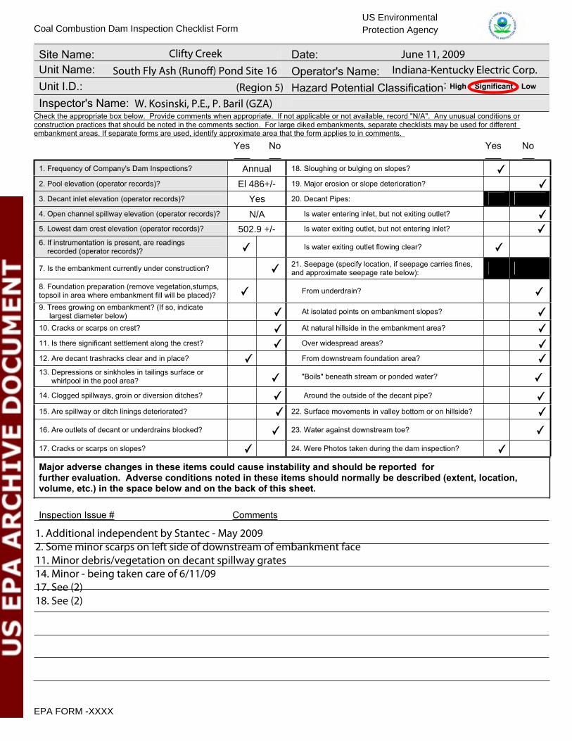
Clifty Creek June 11, 2009South Fly Ash (Runoff) Pond Site 16 Indiana-Kentucky Electric Corp.
(Region 5)W. Kosinski, P.E., P. Baril (GZA)
Annual
El 486+/-
Yes
N/A
502.9 +/-
1. Additional independent by Stantec - May 20092. Someminor scarps on left side of downstream of embankment face11. Minor debris/vegetation on decant spillway grates14. Minor - being taken care of 6/11/0917. See (2)18. See (2)
✔
✔
✔
✔
✔
✔
✔
✔
✔
✔
✔
✔
✔
✔
✔
✔
✔
✔
✔
✔
✔
✔
✔
✔
✔
✔
✔

U. S. Environmental Protection Agency
Coal Combustion Waste (CCW)
Impoundment Inspection
Impoundment NPDES Permit # _____________________ INSPECTOR______________________ Date ____________________________________ Impoundment Name ________________________________________________________ Impoundment Company ____________________________________________________ EPA Region ___________________ State Agency (Field Office) Addresss __________________________________________ __________________________________________Name of Impoundment _____________________________________________________ (Report each impoundment on a separate form under the same Impoundment NPDES Permit number) New ________ Update _________ Yes No Is impoundment currently under construction? ______ ______ Is water or ccw currently being pumped into the impoundment? ______ ______ IMPOUNDMENT FUNCTION: _____________________________________________ Nearest Downstream Town : Name ____________________________________ Distance from the impoundment __________________________ Impoundment Location: Longitude ______ Degrees ______ Minutes ______ Seconds Latitude ______ Degrees ______ Minutes ______ Seconds State _________ County ___________________________ Does a state agency regulate this impoundment? YES ______ NO ______ If So Which State Agency?___________________________________________
EPA Form XXXX-XXX, Jan 09 1

HAZARD POTENTIAL (In the event the impoundment should fail, the following would occur): ______ LESS THAN LOW HAZARD POTENTIAL: Failure or misoperation of the dam results in no probable loss of human life or economic or environmental losses. ______ LOW HAZARD POTENTIAL: Dams assigned the low hazard potential classification are those where failure or misoperation results in no probable loss of human life and low economic and/or environmental losses. Losses are principally limited to the owner’s property. ______ SIGNIFICANT HAZARD POTENTIAL: Dams assigned the significant hazard potential classification are those dams where failure or misoperation results in no probable loss of human life but can cause economic loss, environmental damage, disruption of lifeline facilities, or can impact other concerns. Significant hazard potential classification dams are often located in predominantly rural or agricultural areas but could be located in areas with population and significant infrastructure. ______ HIGH HAZARD POTENTIAL: Dams assigned the high hazard potential classification are those where failure or misoperation will probably cause loss of human life. DESCRIBE REASONING FOR HAZARD RATING CHOSEN: _________________________________________________________________ _________________________________________________________________ _________________________________________________________________ _________________________________________________________________ _________________________________________________________________ _________________________________________________________________ _________________________________________________________________ _________________________________________________________________ _________________________________________________________________ _________________________________________________________________ _________________________________________________________________ _________________________________________________________________ _________________________________________________________________ _________________________________________________________________ _________________________________________________________________
EPA Form XXXX-XXX, Jan 09 2

CONFIGURATION:
Height
original ground
CROSS-VALLEY
Height original ground
SIDE-HILL
Water or ccw
DIKED
original ground Height
Height
original ground
CROSS-VALLEY
Water or ccw
original ground
SIDE-HILL
Height
original
ground
CROSS-VALLEY
original ground
SIDE-HILL
original ground
SIDE-HILL
original ground
SIDE-HILL
original original ground ground
SIDE-HILL SIDE-HILL
original ground
SIDE-HILL SIDE-HILL
original ground Height
SIDE-HILL SIDE-HILL SIDE-HILL
Height Height original ground original ground Height
SIDE-HILL
original ground Height
SIDE-HILL
Water or ccw
original ground Height
SIDE-HILL
INCISED
Water or ccw
original ground
_____ Cross-Valley _____ Side-Hill _____ Diked _____ Incised (form completion optional) _____ Combination Incised/Diked Embankment Height __________ feet Embankment Material_______________Pool Area __________________ acres Liner ____________________________ Current Freeboard ___________ feet Liner Permeability _________________ EPA Form XXXX-XXX, Jan 09 3

TYPE OF OUTLET (Mark all that apply)
TRAPEZOIDAL
Avg Depth
Bottom Width
Depth
TRIANGULAR _____ Open Channel Spillway _____ Trapezoidal Top Width Top Width
_____ Triangular
RECTANGULAR IRREGULAR
Depth _____ Rectangular _____ Irregular _____ depth _____ bottom (or average) width
Width
Depth
Average Width
_____ top width
_____ Outlet _____ inside diameter
Material Inside Diameter
_____ corrugated metal _____ welded steel _____ concrete _____ plastic (hdpe, pvc, etc.) _____ other (specify) ____________________
Is water flowing through the outlet? YES _______ NO _______ _____ No Outlet
_____ Other Type of Outlet (specify) ________________________________ The Impoundment was Designed By ____________________________________ __________________________________________________________________
EPA Form XXXX-XXX, Jan 09 4

Has there ever been a failure at this site? YES __________ NO ___________ If So When? ___________________________ If So Please Describe : _____________________________________________ __________________________________________________________________ __________________________________________________________________ __________________________________________________________________ __________________________________________________________________ __________________________________________________________________ __________________________________________________________________ __________________________________________________________________ __________________________________________________________________ __________________________________________________________________ __________________________________________________________________ __________________________________________________________________ __________________________________________________________________ __________________________________________________________________ __________________________________________________________________ __________________________________________________________________ __________________________________________________________________ __________________________________________________________________ __________________________________________________________________ __________________________________________________________________ __________________________________________________________________ __________________________________________________________________ __________________________________________________________________ __________________________________________________________________ __________________________________________________________________ __________________________________________________________________ __________________________________________________________________ __________________________________________________________________ __________________________________________________________________ __________________________________________________________________ __________________________________________________________________ __________________________________________________________________ __________________________________________________________________
EPA Form XXXX-XXX, Jan 09 5

Has there ever been significant seepages at this site? YES _______ NO _______ If So When? ___________________________ IF So Please Describe: _______________________________________________ __________________________________________________________________ __________________________________________________________________ __________________________________________________________________ __________________________________________________________________ __________________________________________________________________ __________________________________________________________________ __________________________________________________________________ __________________________________________________________________ __________________________________________________________________ __________________________________________________________________ __________________________________________________________________ __________________________________________________________________ __________________________________________________________________ __________________________________________________________________ __________________________________________________________________ __________________________________________________________________ __________________________________________________________________ __________________________________________________________________ __________________________________________________________________ __________________________________________________________________ __________________________________________________________________ __________________________________________________________________ __________________________________________________________________ __________________________________________________________________ __________________________________________________________________ __________________________________________________________________ __________________________________________________________________ __________________________________________________________________ __________________________________________________________________ __________________________________________________________________ __________________________________________________________________ __________________________________________________________________
EPA Form XXXX-XXX, Jan 09 6

Has there ever been any measures undertaken to monitor/lowerPhreatic water table levels based on past seepages or breaches at this site? YES ________NO ________ If so, which method (e.g., piezometers, gw pumping,...)? ____________________ If so Please Describe : ____________________________________________ __________________________________________________________________ __________________________________________________________________ __________________________________________________________________ __________________________________________________________________ __________________________________________________________________ __________________________________________________________________ __________________________________________________________________ __________________________________________________________________ __________________________________________________________________ __________________________________________________________________ __________________________________________________________________ __________________________________________________________________ __________________________________________________________________ __________________________________________________________________ __________________________________________________________________ __________________________________________________________________ __________________________________________________________________ __________________________________________________________________ __________________________________________________________________ __________________________________________________________________ __________________________________________________________________ __________________________________________________________________ __________________________________________________________________ __________________________________________________________________ __________________________________________________________________ __________________________________________________________________ __________________________________________________________________ __________________________________________________________________ __________________________________________________________________ __________________________________________________________________ __________________________________________________________________ __________________________________________________________________
EPA Form XXXX-XXX, Jan 09 7

NAME OF DAM: STATE ID #:
REGISTERED:
STATE SIZE CLASSIFICATION:CHANGE IN HAZARD CLASSIFICATION REQUESTED?: No
CITY/TOWN: COUNTY:
DAM LOCATION: ALTERNATE DAM NAME: Panther Creek Dam(street address if known)
USGS QUAD.: LAT.: LONG.:
DRAINAGE BASIN: Panther Creek RIVER:
DAM SAFETY INSPECTION CHECKLISTSouth Fly Ash Pond 39-12 IN DNR
IN00643NID ID #:
Significant
Madison, Indiana Jefferson
DAM LOCATION INFORMATION
EPA HAZARD CLASSIFICATION:N/A
Tributary to Clifty Creek
Clifty Creek Power Plant
Madison West 38 ̊43' 48" N 85 ̊ 26' 10" W
IMPOUNDMENT NAME(S): Same as above
GENERAL DAM INFORMATION
YES NO
TYPE OF DAM: OVERALL LENGTH (FT):
YEAR BUILT:
STRUCTURAL HEIGHT (FT): EL. NORMAL POOL (FT):
HYDRAULIC HEIGHT (FT): EL. MAXIMUM POOL (FT):
FOR INTERNAL MADCR USE ONLY
FOLLOW-UP INSPECTION REQUIRED: CONDITIONAL LETTER:
NORMAL POOL STORAGE (ACRE-FT): 1750 per NID
Earth embankment 1600
Unknown
PURPOSE OF DAM: Collects surface runoff from Dry Fly Ash landfill
75
1954 MAXIMUM POOL STORAGE (ACRE-FT): 1750 per NID
485
71
YES NO
YES NO YES NO
Dam Safety Inspection Checklist v.3.1 Page 1


NAME OF DAM: STATE ID #:
INSPECTION DATE: NID ID #:
OWNER: CARETAKER:
EMERGENCY PH. # EMERGENCY PH. #FAXEMAILOWNER TYPE
SPILLWAY LENGTH (FT) SPILLWAY CAPACITY (CFS)
AUXILIARY SPILLWAY TYPE AUX. SPILLWAY CAPACITY (CFS)
NUMBER OF OUTLETS OUTLET(S) CAPACITY (CFS)
PRIMARY SPILLWAY TYPE Grated, concrete slopes decant
Private
Unknown
N/A
Varies
None
[email protected] EMAIL
N/A (812) 265-8738(740) 289-7253 FAX (812) 265-8747
N/A1
TOWN, STATE, ZIP Piketon, OH 45661 TOWN, STATE, ZIP Madison, IN 47250PHONE (740) 289-7254 PHONE (812) 265-8715
NAME/TITLE Donald Fulkerson NAME/TITLE Paul de LamerensSTREET P O Box 468, 3932 U.S. Rt. 23 STREET P O Box 97, 1335 Clifty Hollow Road
South Fly Ash Pond 39-12 IN DNR
ORGANIZATION ORGANIZATION IKEC
IN00643
OVEC - IKEC (1)
June 11, 2009
NUMBER OF OUTLETS OUTLET(S) CAPACITY (CFS)
TYPE OF OUTLETS TOTAL DISCHARGE CAPACITY (CFS)
DRAINAGE AREA (SQ MI) SPILLWAY DESIGN FLOOD (PERIOD/CFS)
HAS DAM BEEN BREACHED OR OVERTOPPED IF YES, PROVIDE DATE(S)
FISH LADDER (LIST TYPE IF PRESENT)
DOES CREST SUPPORT PUBLIC ROAD? IF YES, ROAD NAME:
PUBLIC BRIDGE WITHIN 50' OF DAM? IF YES, ROAD/BRIDGE NAME:MHD BRIDGE NO. (IF APPLICABLE)
(1) Ohio Valley Electric Corp./Indiana-Kentucky Electric Corp.
N/A
72-inch RCP
1.1
N/A
Unknown
68 cfs 100 year
1
YES NO
YES NO
YES NO
Dam Safety Inspection Checklist v.3.1 Page 3

NAME OF DAM: STATE ID #:
INSPECTION DATE: NID ID #:
AREAINSPECTED
XX
XCREST X
XX
XGoodShort grass and weeds at edge of pavement
Minor, crest appears fairly levelCurved so embankment matches natural high points5. HORIZONTAL ALIGNMENT
1. SURFACE TYPE2. SURFACE CRACKING3. SINKHOLES, ANIMAL BURROWS4. VERTICAL ALIGNMENT (DEPRESSIONS)
NO
AC
TIO
N
MO
NIT
OR
REP
AIR
Minor, at edge of roadway6. RUTS AND/OR PUDDLES7. VEGETATION (PRESENCE/CONDITION)8. ABUTMENT CONTACT
CONDITION OBSERVATIONS
South Fly Ash Pond
June 11, 2009
39 - 12 IN DNR
IN00643
EMBANKMENT (CREST)
Asphalt - former country roadMultiple longitudinal and lateral cracking due to age (55+ years old)None observed
ADDITIONAL COMMENTS:
Dam Safety Inspection Checklist v.3.1 Page 4

NAME OF DAM: STATE ID #:
INSPECTION DATE: NID ID #:
AREAINSPECTED
XXX
D/S XSLOPE X
XX
X
1. WET AREAS (NO FLOW)2. SEEPAGE3. SLIDE, SLOUGH, SCARP4. EMB.-ABUTMENT CONTACT5. SINKHOLE/ANIMAL BURROWS6. EROSION
Dense, tall vegetation at toe near outlet - remove
7. UNUSUAL MOVEMENT8. VEGETATION (PRESENCE/CONDITION)
Scarps as noted in #2Recently mowed; tall grass about 6-8 inches high
See Note 1 belowMinor scarps on main portion (2)Good, right side wet due to surface runoffNone observed
NO
AC
TIO
N
MO
NIT
OR
REP
AIR
Minor, near toe at 72-inch outlet
South Fly Ash Pond
June 11, 2009
39-12 IN DNR
IN00643
EMBANKMENT (D/S SLOPE)
CONDITION OBSERVATIONS
See Note 1 below
ADDITIONAL COMMENTS:
"dike" is located near the left dam abutment.(2) More numerous and deeper scarps located on "saddle dike" portion of slope to the left of natural high ground. This
(1) Numerous wet areas and seepage/flow along right groin from mid-point to toe at 72" outlet pipe headwall - likely due tosteady rainfall occuring the previous day and overnight.
Dam Safety Inspection Checklist v.3.1 Page 5

NAME OF DAM: STATE ID #:
INSPECTION DATE: NID ID #:
AREAINSPECTED
XXX
U/S XSLOPE X X
X
X7. VEGETATION (PRESENCE/CONDITION)
1. SLIDE, SLOUGH, SCARP2. SLOPE PROTECTION TYPE AND COND.3. SINKHOLE/ANIMAL BURROWS4. EMB.-ABUTMENT CONTACT5. EROSION6. UNUSUAL MOVEMENT
CONDITION OBSERVATIONS NO
AC
TIO
N
MO
NIT
OR
EMBANKMENT (U/S SLOPE)
South Fly Ash Pond
June 11, 2009
39-12 IN DNR
IN00643
REP
AIR
immediately above pond normal pool level
None observed
Some riprap from water line up to 3 to 4 feet below the crestNesting turtles near left abutmentGoodMinor
None observed
Good condition; recently mowed; wetland vegetation (weeds) at end
ADDITIONAL COMMENTS: (2) Below the crest
Dam Safety Inspection Checklist v.3.1 Page 6

NAME OF DAM: STATE ID #:
INSPECTION DATE: NID ID #:
AREAINSPECTED
XX
XINSTR. X
XXXXX
6. SURVEY MONUMENTS7. DRAINS8. FREQUENCY OF READINGS9. LOCATION OF READINGS
South Fly Ash Pond
June 11, 2009
39-12 IN DNR
IN00643
3. STAFF GAGE AND RECORDER4. WEIRS
INSTRUMENTATION
MO
NIT
OR
REP
AIR
1. PIEZOMETERS2. OBSERVATION WELLS
CONDITION OBSERVATIONS
Multiple piezometers installed in 1984 (1)Several at toe for groundwater quality (2)Water levels periodically recordedNone
NO
AC
TIO
N
None
At plant (see Matt Smith)
Yes, at right abutmentNo surface water nor toe drainsMonthly
5. INCLINOMETERS
ADDITIONAL COMMENTS:(2) Monitoring associated with fly ash landfill located to the north end of pond(1) During investigations into potential raising of the embankment
Dam Safety Inspection Checklist v.3.1 Page 7

NAME OF DAM: STATE ID #:
INSPECTION DATE: NID ID #:
AREAINSPECTED
MISC.
WHAT:DATE:DATE:DATE:DATE:
South Fly Ash Pond
June 11, 2009
39-12 IN DNR
IN00643
2. RESERVOIR SHORELINE3. RESERVOIR SLOPES
MISCELLANEOUS
CONDITION OBSERVATIONS
Wooded (west); grassed elsewhere1. RESERVOIR DEPTH (AVG)
4. ACCESS ROADS
1954, 1984
GrassedModerate to steep, especially to the west below "Devil's Backbone"
Paved, on crest with access from left abutmentGuarded gate at Plant entrance5. SECURITY DEVICES
7. AVAILABILITY OF PLANS6. VANDALISM OR TRESPASS
9. AVAILABILITY OF EAP/LAST UPDATE8. AVAILABILITY OF DESIGN CALCS
10. AVAILABILITY OF O&M MANUAL
YES NOYES NOYES NOYES NOYES NOYES NO DATE:
PURPOSE:
ADDITIONAL COMMENTS:(7) Some drawings and designer correspondence; most subsurface information obtained from 1984 dam raising feasibililty study.(6) Students from nearby college do trespass onto slope
CSE required if one desires to inspect 72-inch12. CONFINED SPACE ENTRY REQUIREDJune 11, 2009
pipe
11. CARETAKER/OWNER AVAILABLE
YES NOYES NOYES NOYES NOYES NOYES NOYES NO
Dam Safety Inspection Checklist v.3.1 Page 8
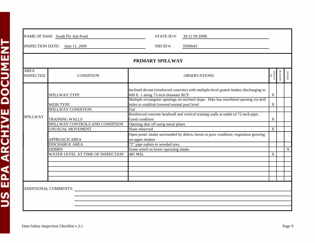
NAME OF DAM: STATE ID #:
INSPECTION DATE: NID ID #:
AREAINSPECTED
X
X
SPILLWAY X
X
South Fly Ash Pond
Inclined decant (reinforced concrete) with multiple-level grated intakes discharging to 660 ft. ± along 72-inch diameter RCPSPILLWAY TYPE
CONDITION
39-12 IN DNR
June 11, 2009
OBSERVATIONS
UNUSUAL MOVEMENT
APPROACH AREA
IN00643
Open pond; intake surrounded by debris; boom in poor condition; vegetation growing on upper intakes
WEIR TYPESPILLWAY CONDITION
TRAINING WALLSSPILLWAY CONTROLS AND CONDITION
PRIMARY SPILLWAY
NO
AC
TIO
N
MO
NIT
OR
REP
AIR
None observed
Multiple rectangular openings on inclined slope. Dike has retrofitted opening via drill holes to establish lowered normal pool levelFairReinforced concrete headwall and vertical training walls at outlet of 72-inch pipe; Good conditionOpening shut off using metal plates
XX
ADDITIONAL COMMENTS:
Some noted on lower operating intake485 MSLWATER LEVEL AT TIME OF INSPECTION
DISCHARGE AREADEBRIS
72" pipe outlets to wooded area
Dam Safety Inspection Checklist v.3.1 Page 9

NAME OF DAM: STATE ID #:
INSPECTION DATE: NID ID #:
AREAINSPECTED
SPILLWAY
DEBRISWATER LEVEL AT TIME OF INSPECTION
SPILLWAY TYPEWEIR TYPE
AUXILIARY SPILLWAY
NO
AC
TIO
N
MO
NIT
OR
REP
AIR
APPROACH AREADISCHARGE AREA
South Fly Ash Pond 39-12 IN DNR
June 11, 2009 IN00643
OBSERVATIONSCONDITION
SPILLWAY CONDITIONTRAINING WALLSSPILLWAY CONTROLS AND CONDITIONUNUSUAL MOVEMENT N/A
ADDITIONAL COMMENTS: No auxiliary spillway
N/A
Dam Safety Inspection Checklist v.3.1 Page 10

NAME OF DAM: STATE ID #:
INSPECTION DATE: NID ID #:
AREAINSPECTED
OUTLETWORKS
OUTLET WORKS (1)
DEBRIS/BLOCKAGEUNUSUAL MOVEMENT
TRASHRACKPRIMARY CLOSURESECONDARY CLOSURECONDUITOUTLET STRUCTURE/HEADWALLEROSION ALONG TOE OF DAM
South Fly Ash Pond
June 11, 2009
39-12 IN DNR
IN00643
TYPEINTAKE STRUCTURE
CONDITION OBSERVATIONS
(See Spillway - Page 9)
NO
AC
TIO
N
MO
NIT
OR
REP
AIR
SEEPAGE/LEAKAGE
Dam Safety Inspection Checklist v.3.1 Page 11
ADDITIONAL COMMENTS:
MISCELLANEOUS
DOWNSTREAM AREA
Note: decant spillway intake and 72" diameter pipe is the only outlet at the dam. There is NO separate outlet works.
Dam Safety Inspection Checklist v.3.1 Page 11
APPENDIX D
DEFINITIONS
COMMON DAM SAFETY DEFINITIONS For a comprehensive list of dam engineering terminology and definitions refer to references published by the U.S. Army Corps of Engineers, the Federal Energy Regulatory Commission, the Department of the Interior Bureau of Reclamation, or the Federal Emergency Management Agency.
Orientation Upstream – Shall mean the side of the dam that borders the impoundment. Downstream – Shall mean the high side of the dam, the side opposite the upstream side.
Right – Shall mean the area to the right when looking in the downstream direction. Left – Shall mean the area to the left when looking in the downstream direction. Dam Components Dam – Shall mean any artificial barrier, including appurtenant works, which impounds or diverts water.
Embankment – Shall mean the fill material, usually earth or rock, placed with sloping sides, such that it forms a permanent barrier that impounds water.
Crest – Shall mean the top of the dam, usually provides a road or path across the dam.
Abutment – Shall mean that part of a valley side against which a dam is constructed. An artificial abutment is sometimes constructed as a concrete gravity section, to take the thrust of an arch dam where there is no suitable natural abutment.
Appurtenant Works – Shall mean structures, either in dams or separate there from, including but not be limited to, spillways; reservoirs and their rims; low level outlet works; and water conduits including tunnels, pipelines, or penstocks, either through the dams or their abutments. Spillway – Shall mean a structure over or through which water flows are discharged. If the flow is controlled by gates or boards, it is a controlled spillway; if the fixed elevation of the spillway crest controls the level of the impoundment, it is an uncontrolled spillway.
General EAP – Emergency Action Plan - Shall mean a predetermined plan of action to be taken to reduce the potential for property damage and/or loss of life in an area affected by an impending dam break. O&M Manual – Operations and Maintenance Manual; Document identifying routine maintenance and operational procedures under normal and storm conditions. Normal Pool – Shall mean the elevation of the impoundment during normal operating conditions. Acre-foot – Shall mean a unit of volumetric measure that would cover one acre to a depth of one foot. It is equal to 43,560 cubic feet. One million U.S. gallons = 3.068 acre feet.

Height of Dam – Shall mean the vertical distance from the lowest portion of the natural ground, including any stream channel, along the downstream toe of the dam to the crest of the dam. Spillway Design Flood (SDF) – Shall mean the flood used in the design of a dam and its appurtenant works particularly for sizing the spillway and outlet works, and for determining maximum temporary storage and height of dam requirements. Condition Rating SATISFACTORY - No existing or potential management unit safety deficiencies are recognized. Acceptable performance is expected under all applicable loading conditions (static, hydrologic, seismic) in accordance with the applicable criteria. Minor maintenance items may be required. FAIR - Acceptable performance is expected under all required loading conditions (static, hydrologic, seismic) in accordance with the applicable safety regulatory criteria. Minor deficiencies may exist that require remedial action and/or secondary studies or investigations. POOR - A management unit safety deficiency is recognized for any required loading condition (static, hydrologic, seismic) in accordance with the applicable dam safety regulatory criteria. Remedial action is necessary. POOR also applies when further critical studies or investigations are needed to identify any potential dam safety deficiencies. UNSATISFACTORY - Considered unsafe. A dam safety deficiency is recognized that requires immediate or emergency remedial action for problem resolution. Reservoir restrictions may be necessary. Hazard Potential (In the event the impoundment should fail, the following would occur): LESS THAN LOW HAZARD POTENTIAL: Failure or misoperation of the dam results in no probable loss of human life or economic or environmental losses. LOW HAZARD POTENTIAL: Dams assigned the low hazard potential classification are those where failure or misoperation results in no probable loss of human life and low economic and/or environmental losses. Losses are principally limited to the owner’s property. SIGNIFICANT HAZARD POTENTIAL: Dams assigned the significant hazard potential classification are those dams where failure or misoperation results in no probable loss of human life but can cause economic loss, environmental damage, disruption of lifeline facilities, or can impact other concerns. Significant hazard potential classification dams are often located in predominantly rural or agricultural areas but could be located in areas with population and significant infrastructure. HIGH HAZARD POTENTIAL: Dams assigned the high hazard potential classification are those where failure or misoperation will probably cause loss of human life. J:\01.0170142.00\Inspections\Clifty Creek, IN\Inspections\West Bottom Ash Pond\definitiions.doc