client side telephony (cst) chipset mode - ti.com · cst host terminal window 8 ... adpcm adaptive...
TRANSCRIPT

Application ReportSPRA859 - January 2003
1
www.spiritDSP.com/CST
Client Side Telephony (CST) Chipset ModeLeonid PurtoMaxim Silchev
SPIRIT CORP
ABSTRACT
The purpose of this document is to provide information required to test the basic functionalityof the C54CST data modem and voice applications in chipset mode. It is recommended thatthis testing be done on the TMS320C54CST evaluation module (EVM) board for quickverification, but other custom platforms may be used.
A list of required equipment (hardware) will be presented, along with the hardware installationsteps. Two software methods of using the client side telephony (CST) chip will be presented:controlling the chipset using a voice and data terminal application (CSTHost), and using awindows Dial-up Networking session to connect to an ISP. Step-by-step instructions will beprovided to guide you through the setup required for each of these methods.
Contents
1 Introduction 2. . . . . . . . . . . . . . . . . . . . . . . . . . . . . . . . . . . . . . . . . . . . . . . . . . . . . . . . . . . . . . . . . . . . . . . . . 1.1 Abbreviations and Acronyms 3. . . . . . . . . . . . . . . . . . . . . . . . . . . . . . . . . . . . . . . . . . . . . . . . . . . . . . .
2 Quick Start 4. . . . . . . . . . . . . . . . . . . . . . . . . . . . . . . . . . . . . . . . . . . . . . . . . . . . . . . . . . . . . . . . . . . . . . . . . . 2.1 Required Equipment 4. . . . . . . . . . . . . . . . . . . . . . . . . . . . . . . . . . . . . . . . . . . . . . . . . . . . . . . . . . . . . . 2.2 Hardware Installation 5. . . . . . . . . . . . . . . . . . . . . . . . . . . . . . . . . . . . . . . . . . . . . . . . . . . . . . . . . . . . . 2.3 LED Indication 5. . . . . . . . . . . . . . . . . . . . . . . . . . . . . . . . . . . . . . . . . . . . . . . . . . . . . . . . . . . . . . . . . . .
3 CST Host 6. . . . . . . . . . . . . . . . . . . . . . . . . . . . . . . . . . . . . . . . . . . . . . . . . . . . . . . . . . . . . . . . . . . . . . . . . . . . 3.1 Application Files 6. . . . . . . . . . . . . . . . . . . . . . . . . . . . . . . . . . . . . . . . . . . . . . . . . . . . . . . . . . . . . . . . . . 3.2 CST Host Settings 7. . . . . . . . . . . . . . . . . . . . . . . . . . . . . . . . . . . . . . . . . . . . . . . . . . . . . . . . . . . . . . . .
3.2.1 Voice Mode Settings 9. . . . . . . . . . . . . . . . . . . . . . . . . . . . . . . . . . . . . . . . . . . . . . . . . . . . . . . . 3.2.2 Modem Settings 10. . . . . . . . . . . . . . . . . . . . . . . . . . . . . . . . . . . . . . . . . . . . . . . . . . . . . . . . . . 3.2.3 Loading Settings 11. . . . . . . . . . . . . . . . . . . . . . . . . . . . . . . . . . . . . . . . . . . . . . . . . . . . . . . . . .
3.3 CST Host COM Port Settings 11. . . . . . . . . . . . . . . . . . . . . . . . . . . . . . . . . . . . . . . . . . . . . . . . . . . . . 3.4 DAA International Settings 12. . . . . . . . . . . . . . . . . . . . . . . . . . . . . . . . . . . . . . . . . . . . . . . . . . . . . . . . 3.5 Loading the Patch Code or Flex Application 14. . . . . . . . . . . . . . . . . . . . . . . . . . . . . . . . . . . . . . . . .
4 Running Voice and Data Modem Demos Using CST Host 15. . . . . . . . . . . . . . . . . . . . . . . . . . . . . . 4.1 Voice Demos 15. . . . . . . . . . . . . . . . . . . . . . . . . . . . . . . . . . . . . . . . . . . . . . . . . . . . . . . . . . . . . . . . . . . .
4.1.1 Detect Caller ID 16. . . . . . . . . . . . . . . . . . . . . . . . . . . . . . . . . . . . . . . . . . . . . . . . . . . . . . . . . . . 4.1.2 Play a Greeting and Record a New Message 16. . . . . . . . . . . . . . . . . . . . . . . . . . . . . . . . . 4.1.3 Record a New Message 16. . . . . . . . . . . . . . . . . . . . . . . . . . . . . . . . . . . . . . . . . . . . . . . . . . . 4.1.4 Play Back a Recorded Message 17. . . . . . . . . . . . . . . . . . . . . . . . . . . . . . . . . . . . . . . . . . . .
4.2 Data Modem Demos 17. . . . . . . . . . . . . . . . . . . . . . . . . . . . . . . . . . . . . . . . . . . . . . . . . . . . . . . . . . . . .
Trademarks are the property of their respective owners.

SPRA859
2 Client Side Telephony (CST) Chipset Mode
5 Using the CST Model via Dial-Up Networking 17. . . . . . . . . . . . . . . . . . . . . . . . . . . . . . . . . . . . . . . . . 5.1 C54CST Windows Device Driver Installation 17. . . . . . . . . . . . . . . . . . . . . . . . . . . . . . . . . . . . . . . . 5.2 Setting Up a Dial-Up Networking Session 23. . . . . . . . . . . . . . . . . . . . . . . . . . . . . . . . . . . . . . . . . . .
6 References 30. . . . . . . . . . . . . . . . . . . . . . . . . . . . . . . . . . . . . . . . . . . . . . . . . . . . . . . . . . . . . . . . . . . . . . . . .
List of Figures
Figure 1. General Hardware Setup of the CST Chip 4. . . . . . . . . . . . . . . . . . . . . . . . . . . . . . . . . . . . . . . . . . . Figure 2. CST Host Terminal Window 8. . . . . . . . . . . . . . . . . . . . . . . . . . . . . . . . . . . . . . . . . . . . . . . . . . . . . . . Figure 3. Settings Window 9. . . . . . . . . . . . . . . . . . . . . . . . . . . . . . . . . . . . . . . . . . . . . . . . . . . . . . . . . . . . . . . . . Figure 4. COM Port Settings 12. . . . . . . . . . . . . . . . . . . . . . . . . . . . . . . . . . . . . . . . . . . . . . . . . . . . . . . . . . . . . . Figure 5. International Settings 14. . . . . . . . . . . . . . . . . . . . . . . . . . . . . . . . . . . . . . . . . . . . . . . . . . . . . . . . . . . . Figure 6. Binary Files Loader 15. . . . . . . . . . . . . . . . . . . . . . . . . . . . . . . . . . . . . . . . . . . . . . . . . . . . . . . . . . . . . . Figure 7. Modem Properties Before CST Installation 18. . . . . . . . . . . . . . . . . . . . . . . . . . . . . . . . . . . . . . . . . Figure 8. Modem Autodetection 19. . . . . . . . . . . . . . . . . . . . . . . . . . . . . . . . . . . . . . . . . . . . . . . . . . . . . . . . . . . Figure 9. Modem Installation 20. . . . . . . . . . . . . . . . . . . . . . . . . . . . . . . . . . . . . . . . . . . . . . . . . . . . . . . . . . . . . . Figure 10. Modem Connection 21. . . . . . . . . . . . . . . . . . . . . . . . . . . . . . . . . . . . . . . . . . . . . . . . . . . . . . . . . . . . Figure 11. Completing Modem Installation 22. . . . . . . . . . . . . . . . . . . . . . . . . . . . . . . . . . . . . . . . . . . . . . . . . . . Figure 12. Modem Properties Window 23. . . . . . . . . . . . . . . . . . . . . . . . . . . . . . . . . . . . . . . . . . . . . . . . . . . . . . Figure 13. Network Connection Wizard 24. . . . . . . . . . . . . . . . . . . . . . . . . . . . . . . . . . . . . . . . . . . . . . . . . . . . . Figure 14. Network Connection Type 25. . . . . . . . . . . . . . . . . . . . . . . . . . . . . . . . . . . . . . . . . . . . . . . . . . . . . . . Figure 15. Device Selection 26. . . . . . . . . . . . . . . . . . . . . . . . . . . . . . . . . . . . . . . . . . . . . . . . . . . . . . . . . . . . . . . Figure 16. Phone Number Selection 27. . . . . . . . . . . . . . . . . . . . . . . . . . . . . . . . . . . . . . . . . . . . . . . . . . . . . . . . Figure 17. Connection Availability 28. . . . . . . . . . . . . . . . . . . . . . . . . . . . . . . . . . . . . . . . . . . . . . . . . . . . . . . . . . Figure 18. Connection Setup Completion 29. . . . . . . . . . . . . . . . . . . . . . . . . . . . . . . . . . . . . . . . . . . . . . . . . . . Figure 19. Dial-Up Connection 30. . . . . . . . . . . . . . . . . . . . . . . . . . . . . . . . . . . . . . . . . . . . . . . . . . . . . . . . . . . .
List of Tables
Table 1. Abbreviations and Acronyms 3. . . . . . . . . . . . . . . . . . . . . . . . . . . . . . . . . . . . . . . . . . . . . . . . . . . . . . . Table 2. Indication of LEDs’ Meaning 6. . . . . . . . . . . . . . . . . . . . . . . . . . . . . . . . . . . . . . . . . . . . . . . . . . . . . . . . Table 3. List of Files for This Application 7. . . . . . . . . . . . . . . . . . . . . . . . . . . . . . . . . . . . . . . . . . . . . . . . . . . . . Table 4. Country-Specific DAA Register Settings 13. . . . . . . . . . . . . . . . . . . . . . . . . . . . . . . . . . . . . . . . . . . . .
1 Introduction
The purpose of this document is to provide information required to test the basic functionality ofthe C54CST data modem and voice applications in chipset mode. It is recommended that thistesting be done on the TMS320C54CST evaluation module (EVM) board for quick verification,but other custom platforms may be used.
A list of required equipment (hardware) will be presented, along with the hardware installationsteps. Two software methods of using the client side telephony (CST) chip will be presented:controlling the chipset using a voice and data terminal application (CSTHost), and using awindows Dial-up Networking session to connect to an ISP. Step-by-step instructions will beprovided to guide you through the setup required for each of these methods.

SPRA859
3 Client Side Telephony (CST) Chipset Mode
1.1 Abbreviations and Acronyms
A list of abbreviations and acronyms in the document are shown in Table 1.
Table 1. Abbreviations and Acronyms
Name Description
ADC Analog-digital converter
ADPCM Adaptive differential pulse code modulation. A type of waveform coding implemented inG.726 codec.
AGC Automatic gain control
CID Caller ID
Chipset Mode Mode of CST chip operation when it is controlled only externally, via assembly test (AT) commandssent over serial link.
CNG Comfort noise generator
CPTD Call progress tone detector
CST Client side telephony, also means the CST chip solution
DAA Data access arrangement, hardware interface with telephone line
DAC Digital-analog converter
DTMF Dual-tone modulated frequency signal
EVM TMS320C54CST evaluation module supplied by Spectrum Digital.
Flex Mode Mode of CST chip operation when it is controlled internally by a user program loaded into internal orexternal memory of the CST chip.
ISP Internet service provider
PCM Pulse code modulation. This term means representation of a waveform by quantized digital signalusing linear or logarithmic laws, rather than a modulation technique.
PSTN Public switched telephone network
UART Universal asynchronous receiver/transmitter, the chip which allows data exchange over serial link
VAD Voice activity detector
XDAIS, XDAS TMS320 DSP algorithm standard (Also known as eXpressDSP).
Notice on DAA part number:
Throughout the document, Silicon Lab’s DAA is referred to as Si3016 or Si3044 chip. Here is theexplanation of part names:
Si3016 – line-side DAA, directly connected to telephone line. External chip.Si3021 – DSP-side DAA, connected to line-side only via capacitors. This part is on-chip in C54CST chip.Si3044 – compound part name, denoting Si3016 and Si3021 together.

SPRA859
4 Client Side Telephony (CST) Chipset Mode
Notice on C54CST part number:
The TMS320VC54CST chip is a current verion of the chip, having CST bundle V2.0 in ROM,and is also referred to as CST2.
TMX320VC54CST chip is a previous verion of the chip, having CST bundle V1.0 in ROM, and is alsoreferred as CST1.
Throughout the document, the C54CST name refers to both of these chips, unless notedotherwise.
2 Quick Start
There are two main modes of the CST chip operation – Chipset mode and Flex mode.
In Chipset mode, only CST software is running inside the CST chip. It is controlled from outsidevia serial link by AT commands. In this mode, the CST chip can be used as standard datamodem with voice features, including duplex voice transfer (all standard functionality of CSTsoftware is accessible via AT commands).
The CST chip does not require any external random-access memory (RAM) or other hardwareto run CST tasks. At the same time, it is possible to load additional code to control the CST chipinto the internal RAM of the TMS320C54CST, and use CST software in read-only memory(ROM) as a library of XDAIS objects, thus eliminating the need for the host controller.
NOTE: Chipset mode is useful mostly for quick start and verification of chip and EVMoperation. The main and most beneficial mode for CST chip is Flex mode.
The most generic hardware setup for the CST chip is shown in Figure 1.
C54CSTChip
AnalogDAA
Si3016PSTN
SeriallinkTelephone
orModem
PCor
MCU
Figure 1. General Hardware Setup of the CST Chip
This document concentrates mostly on usage 54CST chip in chipset mode.
2.1 Required Equipment
The following pieces of equipment are required to correctly setup and test the C54CST chipset:
• Spectrum Digital Incorporated TMS320VC54CST EVM board with 54CST DSP
• Analog Telephone Line
• RJ11 telephone cable with TIP and RING on the inner 2 wires (US version)

SPRA859
5 Client Side Telephony (CST) Chipset Mode
• RS232 DB9 female-to-female STRAIGHT THROUGH modem cable
• Personal computer (PC) with the following minimum specifications:
– Windows 95/98/ME/2000/XP Operation System
– One (1) free DB9 COM (Serial) Port
– CST Host Application (Terminal)
– Microsoft Dial-Up Networking
– Web Browser
• 5-V Power supply
2.2 Hardware Installation
Follow the steps below to correctly install the hardware components.
1. Connect the RS232 cable between the C54CST EVM board and the DB9 COM port onyour PC. Note which COM port you are connecting to on your PC. Typically, this is COM1.
2. Connect the RJ11 telephone cable from your telephone line socket to the RJ11 socket onthe C54CST EVM board.
3. Connect the 5-V power supply to the black socket, J3, on the C54CST EVM board.
4. Be sure that the jumper on the C54CST EVM board is set the following way (ON – pins 1and 2 connected, OFF – pins 2 and 3 connected):
JP1 – OFF JP2 – OFF
JP3 – OFF JP4 – ON
JP5 – OFF JP6 – OFF
5. Power up the board by turning switch SW2 on the C54CST EVM board away from theRS232 connector.
6. Type AT symbols via terminal, connected to EMV’s UART to start TMS320C54CST inChipset mode.
2.3 LED Indication
The C54CST chip uses its input/output (I/O) Port #0 to output indication information about someof the internal events. On Spectrum Digital’s EVM this port is connected to 4 light-emittingdiodes (LEDs), DS3 through DS6.
The meaning of this indication is described in Table 2:

SPRA859
6 Client Side Telephony (CST) Chipset Mode
Table 2. Indication of LEDs’ Meaning
Data Bit No.in Port 0
EVMLED No.
CST’sLED No. Meaning
0 DS3 LED0 Not enough MIPS for real-time operation
This LED is toggled every time a buffer in the DAA driver or UART driveroverflows. Buffer overflow usually happens when some parts of the codeconsume so many MIPS that the CST framework consumes less data fromthese buffers than it is supposed to, according to real-time requirements (forexample, 8000 samples per second from the DAA).
1 DS4 LED1 Voice buffer underrun
Voice controller has a buffer-storing bitstream to be decoded and played out invoice mode. This LED is toggled every time this buffer underruns. Thishappens when the host does not send the bitstream to be played out fastenough, and this leads to interruptions in the output voice signal andsometimes even to incorrect decoding of further bitstream.
2 DS5 LED2 CTS (clear-to-send) circuit state
When the CST’s UART driver receive buffer gets filled to 3/4 of its size(capacity), the driver turns OFF CTS circuit, telling the host to wait and notsend data. When the buffer frees up to 1/2 of its size, the driver turns CTScircuit back ON.
3 DS6 LED3 DSP in IDLE Mode (power saving)
When the power-saving mode is enabled (via ATP command), this LED isturned on when the DSP enters IDLE mode, and is turned off when the DSPleaves IDLE mode. This LED allows you to estimate roughly how loaded theDSP is MIPS-wise: the darker this LED is, the more time the DSP spendsprocessing th eCST’s routines, and the less time it spends in IDLE mode.When power-saving mode is disabled, this LED should be off.
If you need to use I/O Port 0 for some other purposes, it is possible to reload the CST peripheraldriver in Flex mode.
3 CST Host
To better control the CST chip over serial link, SPIRIT has developed a special PC application –CST Host. It can be used as a terminal in data mode, as a play and record utility in voice mode,and it also simplifies setting the CST chip settings.
3.1 Application Files
Table 3 lists files needed to run CST Host application.

SPRA859
7 Client Side Telephony (CST) Chipset Mode
Table 3. List of Files for This Application
File Name Purpose
CST Host.exe Main executable
CSTPatch_ROM1.hex Patch for CST Rom 1.0 (TMX version)
CSTPatch_ROM2.hex Patch for CST Rom 2.0 (TMS version)
CST_Greeting.wav Initial greeting file, mono, 8 kHz sampling rate, 14 bit samples
CST_Greeting_PCM.bin Initial greeting file, G.711 64 kbps/sec
CST_Greeting_A40.bin Initial greeting file, G.726 40 kbps/sec
CST_Greeting_A32.bin Initial greeting file, G.726 32 kbps/sec
CST_Greeting_A24.bin Initial greeting file, G.726 24 kbps/sec
CST_Greeting_A16.bin Initial greeting file, G.726 16 kbps/sec
3.2 CST Host Settings
The steps below are procedures for starting and setting up the CST voice and data terminalapplication, CST Host.
Start CST Host by clicking CSTHost.exe. The CST Host screen, shown in Figure 2, will appear.Power up the C54CST EVM board. If you are using the CST1.0 silicon (TMX version), the CSTgreeting message will only be displayed after downloading the patch code (there is no othersimple way to switch CST1 into chipset mode but via loading a patch).

SPRA859
8 Client Side Telephony (CST) Chipset Mode
Figure 2. CST Host Terminal Window
The number of rings field in the CST host terminal window contains the amount of rings the CSThost should wait before sending an off-hook command to CST chip.
In the CST Host window, click the Settings tab to get the settings window, shown in Figure 3, tochange the CST chip and host settings.

SPRA859
9 Client Side Telephony (CST) Chipset Mode
Figure 3. Settings Window
These settings affect the format of the received Caller-ID information, the type of dialing used,and the length of generated DTMF digits, if used. The available options are listed below:
Caller ID (CID)
• Disabled – No CID information displayed.
• Formatted – Decoded CID data formatted before display
• Unformatted – Raw decoded CID data displayed
Dialing mode
• Tone – Dual-tones used for dialing
• Pulse – Line pulses used for dialing
DTMF digit duration
Set the appropriate length for your application.
3.2.1 Voice Mode Settings
These settings affect the CST voice path (encode, decode, echo cancellation) and the storageand playback of compressed voice. The available options are listed below:
Output Gain, dB
Set gain appropriately for your application.
SPRA859
10 Client Side Telephony (CST) Chipset Mode
Echocanceller mode
• Disabled – EC disabled
• No NLP – EC enabled without non-linear processing
• NLP Enabled – EC enabled with non-linear processing
Enable VAD
Check this box to enable VAD.
Enable AGC
Check this box to enable AGC.
Encoder
• G.711 – 64 kbps 64-kbit/sec G.711 encode/decode
• G.726 – 40 kbps 40-kbit/sec G.726 encode/decode
• G.726 – 32 kbps 32-kbit/sec G.726 encode/decode
• G.726 – 24 kbps 24-kbit/sec G.726 encode/decode
• G.726 – 16 kbps 16-kbit/sec G.726 encode/decode
File Format
• Same as encoder (as is) Data files contain encoded voice data with DLE stuffing.
• Wave file (16bit, 8kHz mono) Data files contain raw PCM voice data.
3.2.2 Modem Settings
These settings affect the data modem speed, protocols, and features. Below are the availableoptions:
Fast connect
Check this box to enable fast connect protocol.
Enable V.42 error correction
Check this box to enable the V.42 error correction protocol.
Compression – V.42bis
• Disabled – V.42bis disabled in both directions
• Transmit Direction – V.42bis enabled only in transmit direction
• Receive Direction – V.42bis enabled only in receive direction
• Both Directions – V.42bis enabled in both directions

SPRA859
11 Client Side Telephony (CST) Chipset Mode
Max Speed
• Auto (14400 bps) – Modem will connect at 14400bps or below
• 1200 bps – Modem will connect at 1200 bps or below.
• 2400 bps – Modem will connect at 2400 bps or below.
• 4800 bps – Modem will connect at 4800 bps or below.
• 9600 bps – Modem will connect at 9600 bps or below.
• 12000 bps – Modem will connect at 12000 bps or below.
Output Gain, dB
Set the appropriate gain for your application.
3.2.3 Loading Settings
The changes made above are not automatically transferred to the CST device. After updatingthe settings, click the “Reload settings” button to download these settings to the CST chip.
3.3 CST Host COM Port Settings
Select the COM port to which you connected the RS232 cable.
Click on “Configure port” to get the COM port properties screen, shown in Figure 4. Set the portfor 115200 bps, 8 bits of data, 1 stop bit, no parity, Hardware flow control, and press OK.Type AT<ENTER> to check if the COM was configured correctly, and the EVM can receive andsend data over it. If everything is correct, you should see an echo of the command that youentered, and then the OK response:
ATOK
The CST chip UART driver has a limited capability of autobaud detection, so if for some reasonthe port speed was selected other than 115200, you must help the CST chip to synchronize tothe new baud rate. To do this, keep typing several continuous AT commands without <Enter>until you see the correct echo.

SPRA859
12 Client Side Telephony (CST) Chipset Mode
Figure 4. COM Port Settings
3.4 DAA International Settings
It is important to properly tune the telephony interface (DAA) for the standards of your country(see Table 4).

SPRA859
13 Client Side Telephony (CST) Chipset Mode
Table 4. Country-Specific DAA Register Settings
S-Register 116 117 118
AT bit reference: S116.6OHS
S116.5ACT
S116.2,3DCT[1:0]
S116.1RZ
S116.0RT
S117.4LIM
S118.4VOL
Country
Australia 1 1 01 0 0 0 0
Bulgaria 0 0 or 1 10 0 0 0 0
China 0 0 01 0 0 0 0
CTR21 0 0 or 1 11 0 0 1 0
Czech Republic 0 1 10 0 0 0 0
FCC 0 0 10 0 0 0 0
Hungary 0 0 10 0 0 0 0
Japan 0 0 01 0 0 0 0
Malaysia 0 0 01 0 0 0 0
New Zealand 0 1 10 0 0 0 0
Philippines 0 0 01 0 0 0 1
Poland 0 0 10 1 1 0 0
Singapore 0 0 10 0 0 0 0
Slovakia 0 0 or 1 10 0 0 0 0
Slovenia 0 1 10 0 0 0 0
South Africa 1 1 10 1 0 0 0
South Korea 0 0 01 1 0 0 0
NOTES: 1. CTR21 includes the following countries: Austria, Belgium, Denmark, Finland, France, Germany, Greece, Iceland, Ireland, Italy,Luxembourg, Netherlands, Norway, Portugal, Spain, Sweden, Switzerland, and the United Kingdom.
2. This table is copied from [7] with some modifications, Silicon Laboratories.
Click the “International settings...” button to get the dialog box shown in Figure 5.

SPRA859
14 Client Side Telephony (CST) Chipset Mode
Figure 5. International Settings
In the first field, select the country or standard region you are in. Select “user-defined” if yourcountry or region is not in the pulldown list.
All preset settings for your country/standard will be grayed out, and you need to set only thosethat are not. For further details, refer to the Client Side Telephony (CST) Chip Software User’sGuide (SPRU029).
NOTE: A wrong setting of the “Current line monitor” mode (Low/High) will result in a Caller IDType I detection failure. Should this occur, simply toggle your initial setting, reload the settings,and retest Caller ID.
3.5 Loading the Patch Code or Flex Application
To upgrade CST silicon (this is mostly needed for data modem functionality on the CST1 chip), itis necessary to download a software patch after power up before running any tests/demos.Below are instructions for loading the patch. If you are only using the voice features of CST,there is no need to upload the patch.
Click on the “Load patch0” button to download the software patch. The dialog box window willappear (see Figure 6). Verify that the correct patch file name is selected and click the “Load”button on this window. The patch will then be loaded to the CST chipset. You should see theLEDs on the C54CST EVM blink for a short while and a CST greeting message displayed on theCST Host terminal window.
NOTE: For the CST2 chip, specifically the CSTPatch_ROM2.HEX file should be loaded. Thepatch code MUST be loaded each time the board/device is powered up.

SPRA859
15 Client Side Telephony (CST) Chipset Mode
Figure 6. Binary Files Loader
This option can also be used to download CST Flex applications into CST chip via serial link.
The binary format of the file being downloaded is described in the TMS320VC5407 TechnicalReference CST Bootloader, (SPRA827).
To create a binary file from a Flex application’s *.out file, you just need to run hexCST.bat (fornon-DSP/BIOS -based applications) or hexCST_BIOS.bat (for DSP/BIOS based applications).
Both patch loading and flex application loading has to be done when the CST chip is in its initialstate after reset.
For the CST2 chip, however, it is also possible to load the patch or flex application when CSThas already entered Chipset mode (via an AT command sent to bootloader, for example). In thiscase, option “use command AT#DATA” should be checked.
4 Running Voice and Data Modem Demos Using CST Host
This section provides instructions for running the voice record/playback demos available in CSTHost, and using CST Host as a terminal for controlling the CST modem.
4.1 Voice Demos
These demos play and record compressed voice data stored in the files listed in section 3.1. Thedemos allow you to execute any of the following four applications:
• Detect Caller ID• Play a greeting and record a new message• Record a new message• Playback a recorded message
Important tips for voice demos
• It is highly recommended that you close Code Composer Studio , and any otherapplications you may be running, on your PC. This frees up central processing unit (CPU)resources to prevent loss of real-time speech playback and record.
• Whenever possible, use even G.726 compression rates (16-kbps and 32-kbps). Thisminimizes the chances of loosing bit synchronization whenever real time on PC problemsarise.
DSP/BIOS is a trademark of Texas Instruments.Code Composer Studio is a trademark of Texas Instruments.

SPRA859
16 Client Side Telephony (CST) Chipset Mode
• Make sure that the path and filename of the “Greeting Message” correctly match theselected compression rate. Please refer to “Package Contents” for list of files andcorresponding compression rates. A mismatch of the selected rate and file will result indemos 1, 2, and 3 not starting.
• Should anything go wrong with the demo, simply turn off the power on the C54CST EVM,turn it back on to reset the system, and redo the settings.
• To test Caller ID, ensure that the phone line connected to the C54CST EVM board hasCaller-ID service enabled. You can verify this with your local telephone service provider.
NOTE: The patch code loading is mostly needed for using the data modem functionality inCST1.0 silicon. Voice applications do not need the patch download.
4.1.1 Detect Caller ID
Call the telephone line connected to the C54CST EVM from another line. After the first ring, youwill see a “RING” message displayed on the main terminal window, and then the Caller-IDinformation of the line you are calling from will be displayed.
4.1.2 Play a Greeting and Record a New Message
Click the “Play greetings and record” button. A “waiting for ring” message will appear in the lowergray portion of the terminal. The application is now ready to start as soon as the next newincoming ring is detected. If the Caller-ID detection demo has not been run before this, then youneed to call the telephone line connected to the C54CST EVM from another line.
The call will be answered after the next new ring (off-hook condition) and a greeting messageplayed out. At the same time, you may record a voice message. You do not need to wait for thegreeting message to end. This demonstrates the use of the line echo canceller.
You have 30 seconds to record a message after which the application will playback yourrecorded message. You will be prompted by a message in the lower gray area of the terminalwindow when playback terminates. The application will then hang up the phone line (on-hookcondition).
4.1.3 Record a New Message
Click the “Record” button. A “waiting for ring” message will appear in the lower gray portion ofthe terminal. The application is now ready to start as soon as the next new incoming ring isdetected. If the Caller-ID detection demo has not been run before this, you need to call thetelephone line connected to the C54CST EVM from another line.
The call will be answered after the next new ring (off-hook condition) and recording of your voicemessage will begin immediately.
You have 30 seconds to record a message. You will be prompted when recording terminates bya message in the lower gray area of the terminal window. The application will then hang up thephone line (on-hook condition).

SPRA859
17 Client Side Telephony (CST) Chipset Mode
4.1.4 Play Back a Recorded Message
Click the “Playback recording” button. A “waiting for ring” message will appear in the lower grayportion of the terminal. The application is now ready to start as soon as the next new incomingring is detected. If the Caller-ID detection demo has not been run before this, you need to callthe telephone line connected to the C54CST EVM from another line.
The EVM board will answer after the first ring and start playing back the recorded message inthe file immediately.
You will be prompted when playback terminates (after 30 seconds) by a message in the lowergray area of the terminal window. The application will then hang up the phone line (on-hookcondition).
4.2 Data Modem Demos
The main CST Host terminal window can be used as a standard terminal application (e.g.,HyperTerminal, ProComm, etc.). To do this, simply click in the terminal window and entercommands. The CST modem will respond appropriately. For details on supported ATcommands, refer to the Client Side Telephony (CST) Chip Software User’s Guide (SPRU029).
5 Using the CST Model via Dial-Up Networking
Dial-up Networking allows a connection to be established with an ISP. Desired networkingapplications can then be run over this connection. This section will present the steps involved ininstalling the windows driver for the CST modem, setting up a connection to an ISP, and showhow a web browser application can be run over this connection.
CAUTIONS:For CST1.0 silicon users, the patch code must be loaded each time the board is reset
(powered off and on) before starting a dial-up networking session.
Ensure that there is no active CST Host session while trying to set up a dial-up networking session.
5.1 C54CST Windows Device Driver Installation
Below are the steps required to install the windows device driver for the C54CST modem. This isrequired to be able to set up a windows Dial-up Networking session.
1. Open the Control Panel window.
2. Click the Modems icon.
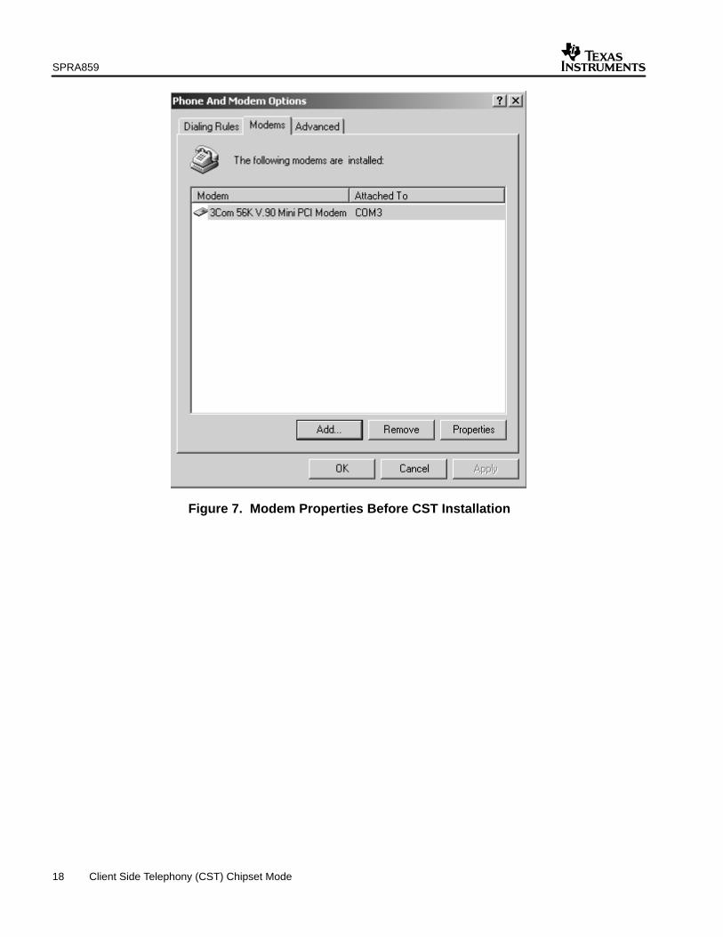
If you already have a modem installed, you will get a screen similar to that shown inFigure 7, showing all modems you have installed. Click the “Add” button to get to the screenshown in Figure 8.
If you don’t have other modems installed, you will get the screen shown in Figure 8 directly.
3. Check the “Don’t detect my modem; I will select from a list” box, and click “Next”.
SPRA859
18 Client Side Telephony (CST) Chipset Mode
Figure 7. Modem Properties Before CST Installation

SPRA859
19 Client Side Telephony (CST) Chipset Mode
Figure 8. Modem Autodetection
The screen in Figure 9 will appear. Select “[Standard Modem Types]” manufacturer, and“Standard 14400 bps modem” model.

SPRA859
20 Client Side Telephony (CST) Chipset Mode
Figure 9. Modem Installation
Click Next to get the screen in Figure 10, and select the port to which the modem is attached.This should be the COM port to which you connected the RS232 cable from the C54CST EVMboard. Typically, this is COM1. After selecting the port, click Next.

SPRA859
21 Client Side Telephony (CST) Chipset Mode
Figure 10. Modem Connection
The screen in Figure 11 will be displayed when the installation is completed. Click Finish tocomplete the installation.

SPRA859
22 Client Side Telephony (CST) Chipset Mode
Figure 11. Completing Modem Installation
The Modem Properties window in Figure 12 will be displayed, showing “Standard 14400 bpsModem” in the list of modems. Your driver installation is now complete. Close this window.

SPRA859
23 Client Side Telephony (CST) Chipset Mode
Figure 12. Modem Properties Window
5.2 Setting Up a Dial-Up Networking Session
This section will present the steps involved in setting up a Dial-up Networking session to connectto an ISP.
To start up a dial-up networking session, do the following:
• Click on the My Computer icon on your desktop.
• In the My Computer window, click the “Network and Dial-up Connection” icon.
• In the Network and Dial-up Connection window, click on the “Make New Connection” icon.
• You will get the “Network Connection Wizard” screen shown in Figure 13. Click “Next”.

SPRA859
24 Client Side Telephony (CST) Chipset Mode
Figure 13. Network Connection Wizard
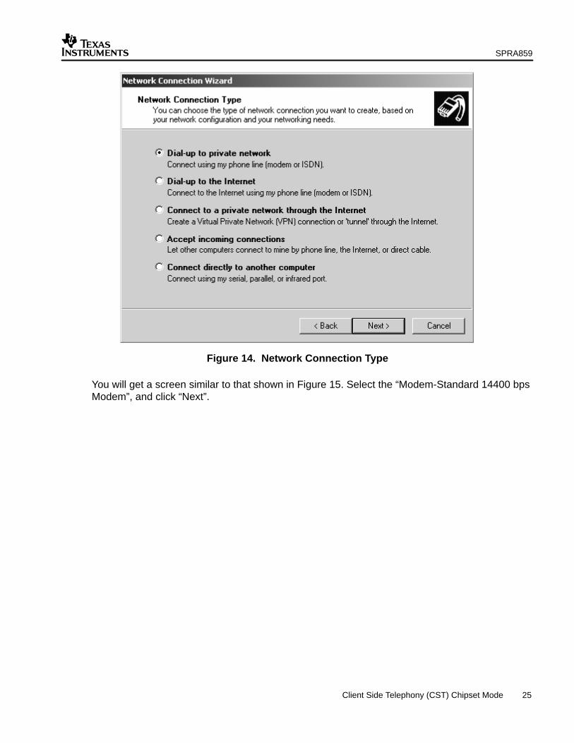
Select the “Dial-up private network” option (Figure 14), and click “Next”.
SPRA859
25 Client Side Telephony (CST) Chipset Mode
Figure 14. Network Connection Type
You will get a screen similar to that shown in Figure 15. Select the “Modem-Standard 14400 bpsModem”, and click “Next”.

SPRA859
26 Client Side Telephony (CST) Chipset Mode
Figure 15. Device Selection
In this screen, select the phone number to dial and the country (Figure 16). Click “Next”.

SPRA859
27 Client Side Telephony (CST) Chipset Mode
Figure 16. Phone Number Selection
You will get a screen similar to that shown in Figure 17. Select “For all users”. Click “Next”.

SPRA859
28 Client Side Telephony (CST) Chipset Mode
Figure 17. Connection Availability
This is the last step of the Network Connection Wizard, shown in Figure 18. Give a name to theconnection, and click “Finish”.

SPRA859
29 Client Side Telephony (CST) Chipset Mode
Figure 18. Connection Setup Completion
In your Dial-up Networking window, there will be a new icon with the name of the connection youjust set up. Click on this icon to get the screen shown in Figure 19.

SPRA859
30 Client Side Telephony (CST) Chipset Mode
Figure 19. Dial-Up Connection
Enter your username and password. If required, click Dial Properties to modify the dialingproperties. Click connect when done to make the connection.
The modem will dial the number and attempt to verify your username and password. If the ISPaccepts this connection, an icon will be displayed in the right corner of the Windows toolbar atthe bottom of your screen.
Start a web browser application to visit some sites.
6 References1. Using the TMS320 DSP Algorithm Standard in a Static DSP System (SPRA577).2. TMS320 DSP Algorithm Standard Rules and Guidelines (SPRU352).3. TMS320 DSP Algorithm Standard API Reference (SPRU360).4. Technical Overview of eXpressDSP-Compliant Algorithms for DSP Software Producers
(SPRA579).5. The TMS320 DSP Algorithm Standard (SPRA581).6. Achieving Zero Overhead with the TMS320 DSP Algorithm Standard IALG Interface
(SPRA716).7. Si3044 User Guide. 3.3 V Enhanced Global Direct Access Arrangement. Silicon Laboratories,
2000. http://www.silabs.com8. TMS320C54CST Client Side Telephony (SPRS187).

SPRA859
31 Client Side Telephony (CST) Chipset Mode
9. TMS320C54CST Bootloader Technical Reference (SPRA853).
10. TMS320C54CST Evaluation Module Technical Reference. Spectrum Digital, Inc.
11. Client Side Telephony (CST) Chip Software User’s Guide (SPRU029).
12. Client Side Telephony (CST) Chip Flex Mode, Flex Examples Description (SPRA862).
13. Go to http://www.ti.com for the latest version of TMS320C54x user’s guides.
14. Go to http://www.spiritDSP.com for the latest version of CST documentation.

IMPORTANT NOTICE
Texas Instruments Incorporated and its subsidiaries (TI) reserve the right to make corrections, modifications,enhancements, improvements, and other changes to its products and services at any time and to discontinueany product or service without notice. Customers should obtain the latest relevant information before placingorders and should verify that such information is current and complete. All products are sold subject to TI’s termsand conditions of sale supplied at the time of order acknowledgment.
TI warrants performance of its hardware products to the specifications applicable at the time of sale inaccordance with TI’s standard warranty. Testing and other quality control techniques are used to the extent TIdeems necessary to support this warranty. Except where mandated by government requirements, testing of allparameters of each product is not necessarily performed.
TI assumes no liability for applications assistance or customer product design. Customers are responsible fortheir products and applications using TI components. To minimize the risks associated with customer productsand applications, customers should provide adequate design and operating safeguards.
TI does not warrant or represent that any license, either express or implied, is granted under any TI patent right,copyright, mask work right, or other TI intellectual property right relating to any combination, machine, or processin which TI products or services are used. Information published by TI regarding third–party products or servicesdoes not constitute a license from TI to use such products or services or a warranty or endorsement thereof.Use of such information may require a license from a third party under the patents or other intellectual propertyof the third party, or a license from TI under the patents or other intellectual property of TI.
Reproduction of information in TI data books or data sheets is permissible only if reproduction is withoutalteration and is accompanied by all associated warranties, conditions, limitations, and notices. Reproductionof this information with alteration is an unfair and deceptive business practice. TI is not responsible or liable forsuch altered documentation.
Resale of TI products or services with statements different from or beyond the parameters stated by TI for thatproduct or service voids all express and any implied warranties for the associated TI product or service andis an unfair and deceptive business practice. TI is not responsible or liable for any such statements.
Mailing Address:
Texas InstrumentsPost Office Box 655303Dallas, Texas 75265
Copyright 2003, Texas Instruments Incorporated