client project - seattle
TRANSCRIPT

GENERAL OBSERVATION REPORTReport Number: M7181304.0627Service Date: 02/07/20 20225 Cedar Valley Rd Ste 110Report Date: 02/13/20 Lynnwood, WA 98036-6365
425-742-9360
Client ProjectPine Street Group LLC WA State Convention Center ExpansionAttn: Webb Miller 1600 9th Ave1500 4th Ave Ste 600 Seattle, WA Seattle, WA 98101-1670 Project No.: M7181304
The tests were performed in general accordance with applicable ASTM, AASHTO, or DOT test methods. This report is exclusively for the use of the client indicated above and shall not be reproduced except in full without the written consent of our company. Test results transmitted herein are only applicable to the actual samples tested at the location(s) referenced and are not necessarily indicative of the properties of other apparently similar or identical materials.
CT0001, 10-16-13, Rev.10 Page 1 of 4
Permit No.: 6501134-PH Weather: OvercastSamples: N/A
Inspector: Dennis Sanborn performed the following inspections.Assisted with daily inspections, reviewed reports.
Inspection for the slab-on-metal-deck at Level 2, grid lines R.2 to T/4 to 8.5 and Level 3 slab-on-metal-deck at grid lines R.2 to U/7 to 10. Reference Mayes Testing Engineers (MTE) report dated 02/03/20. The reinforcement was inspected for size, grade, lap and spacing. The decks have been turned over to the concrete crews and placement was completed on Level 3 slab-on-metal-deck at grid lines R.2 to U/7 to 10.
The edge form construction joint was moved, and the added new section will need to be inspected. The added section was inspected and found to conform to the plans.
Continued the inspection for the slab-on-metal-deck at Level 2, grid lines R.2 to T/3.7 to 8.5 and Level 3 slab-on-metal-deck at grid lines R.2 to U/3.7 to 7 and the ramp at grid lines U.2 to U.8/11 to 11.4 and U.2 to U.8/11 to 6 at Level 2 to 3. The reinforcement is being inspected for size, grade, lap and spacing. The following items need to be completed:
1. Complete the reinforcement placement for the slab-on-metal-deck Type 7 for the ramp. Completed2. Complete the typical slab-on-metal-deck reinforcement placement at Level 2 and 3. Level 3 has been completed,
Level 2 still requires the reinforcement to be completed.3. Install the construction joint forming and reinforcement. Level 3 has been completed, Level 2 still requires the
reinforcement to be completed.4. Complete the trim reinforcement. Completed5. Install edge form reinforcement, CMU, planter and wall dowels for the ramp. The added section was inspected
and found to conform to the plans.6. Install the missing CMU dowels on Level 3 slab-on-metal-deck. Completed7. Verify proper clearances are attained for the reinforcement, especially along the edges. Completed 02/07/20.8. Decking on the ramp at Level 3 needs to be completed. After decking is completed and stud welding performed,
reinforcement needs to be installed and completed. Completed and a new construction joint was installed.9. Notified American Bridge that per RFI 495.1, the added beams for the extended deck edge on the ramp that was
added the added beams will require the installation of shear studs. Completed and studs were tested and found to be acceptable per AWS D1.1.
10. Inspection of support of the rampway also found (2) columns without grouting located at grid lines U.2/4 and U.8/4 on Level 1. American Bridge and Clark Lewis QC were notified. Columns were grouted 02/04/20.
GENERAL OBSERVATION REPORTReport Number: M7181304.0627Service Date: 02/07/20 20225 Cedar Valley Rd Ste 110Report Date: 02/13/20 Lynnwood, WA 98036-6365
425-742-9360
Client ProjectPine Street Group LLC WA State Convention Center ExpansionAttn: Webb Miller 1600 9th Ave1500 4th Ave Ste 600 Seattle, WA Seattle, WA 98101-1670 Project No.: M7181304
The tests were performed in general accordance with applicable ASTM, AASHTO, or DOT test methods. This report is exclusively for the use of the client indicated above and shall not be reproduced except in full without the written consent of our company. Test results transmitted herein are only applicable to the actual samples tested at the location(s) referenced and are not necessarily indicative of the properties of other apparently similar or identical materials.
CT0001, 10-16-13, Rev.10 Page 2 of 4
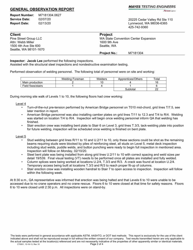
Inspector: Jacob Lee performed the following inspections.Assisted with the structural steel inspections and nondestructive examination testing.
Performed observation of welding personnel. The following total of personnel were on site and working:
Welding Foreman Welders Apprentices/Others TotalMain production 2 10 4 16Field fixes/stairs 1 4 1 6
Subtotal 22
During morning site walk of Levels 1 to 10, the following floors had crew working:
Level 4• Turn-of-the-nut pre-tension performed by American Bridge personnel on T010 mid-chord, grid lines T/7.5, see
later mention in report.• American Bridge personnel was also installing camber plates on grid lines T/11 to 12.3 and T/4 to R/4. Welding
was started on location T/4 to R/4. Inspection will begin once welding personnel inform QA that welding has finished.
• Stair erection crew was installing bent plate to Stair 6 on Level 3, grid lines T.3/3, tack-welding plate into position for future welding, inspection will be scheduled once welding is finished on bent plate.
Level 5• Stud welding between grid lines R/11 to 10 and U.2/11 to 10, only these sections could be shot as the remaining
beams requiring studs were blocked by piles of reinforcing steel, all studs on Level 5, metal deck inspection including stud welds, puddle welds, and button punching were ready to begin full inspection in mentioned area. Inspection will follow on Monday, 02/10/20.
• Steel bent plate was being installed from along grid lines U.2/11 to 10 with correct spacing and weld sizes per detail 19/539. Final visual testing (VT) needs to be performed once all plates are installed and fully welded.
• Column splices were being worked at locations U.2/4, T.3/3 and R/3. A crack was found at location U.2/4. Temporary access being built at locations T.3/3 and R/3 to reach proper fit-up of columns.
• Stair erection crew was installing wooden handrail to Stair 7 to open access to inspection. Inspection will follow within the following week.
At 8:30 a.m., QA representative was informed that erection was being halted and that Levels 6 to 10 were unable to be accessed due to no crane operators and no crane rescue. Floors 6 to 10 were closed at that time for safety reasons. Floors 6 to 10 were closed until 2:30 p.m. All inspections were on stand-by.

GENERAL OBSERVATION REPORTReport Number: M7181304.0627Service Date: 02/07/20 20225 Cedar Valley Rd Ste 110Report Date: 02/13/20 Lynnwood, WA 98036-6365
425-742-9360
Client ProjectPine Street Group LLC WA State Convention Center ExpansionAttn: Webb Miller 1600 9th Ave1500 4th Ave Ste 600 Seattle, WA Seattle, WA 98101-1670 Project No.: M7181304
The tests were performed in general accordance with applicable ASTM, AASHTO, or DOT test methods. This report is exclusively for the use of the client indicated above and shall not be reproduced except in full without the written consent of our company. Test results transmitted herein are only applicable to the actual samples tested at the location(s) referenced and are not necessarily indicative of the properties of other apparently similar or identical materials.
CT0001, 10-16-13, Rev.10 Page 3 of 4
Monitored turn-of-the-nut pre-tension method on Level 3 T010 mid-chord at grid lines T/7.5. Joint was brought to snug-tight and match-marked with a 2/3 mark for bolting by American Bridge personnel. Reference on 1x9-1/2” A409 inspection will continue the following day for turn-of-the-nut. The tensioning process is following the proper turn-of-the-nut procedure submitted by American Bridge and RFI 1920.
During site walk with inspector Dennis Sanborn, QA representatives were alerted of a toe crack on built-up HSS column splice U.2/4 on Level 6. After visual examination of the crack it was found that the crack in question was a 27-1/2” toe crack as well as multiple transverse cracks on both the east and west side. It suspected that the crack on the east side of the column wrapped into the completed welds on both north and south face of the column. Magnetic particle (MT) testing was performed by inspector Everrett Martin (Mistras) on the cracking surfaces to reveal multiple other cracking points in the weld joint, both longitudinal and transverse cracks were found. Under suspicion of the toe crack wrapping into the completed weld and the transverse cracks growing up into the PJP of the built-up HSS, ultrasonic (UT) testing was performed by Everrett Martin on both the finished welds and PJP welds done in factory for informational purposes. UT found that the cracks had wrapped the corners and grown up into the factory welds. At this point, all work was halted by American Bridge welding personnel; waiting engineering response to the proper corrective actions moving ahead. It was determined by American Bridge engineering personnel that gouging the toe crack out of the weld was the correct action; treating the cracks as (2) separate issues, repairing field welds before shop welds. Once gouging began it was determined by QA that the crack went into the parent metal through the entire joint, and above the backing bar. Once again work was halted; awaiting engineering response to the new-found issues. It was decided by engineering that American Bridge welding personnel would then gouge the crack all the way out of the metal and get it ready for MT in the morning before making their next decision. See attached photos for details.
Inspector: Everrett Martin (Mistras) performed the following nondestructive examination inspections.Assisted with the nondestructive examination testing.
Perform UT testing for the Level 6 framing. See the attached report for testing data.

GENERAL OBSERVATION REPORTReport Number: M7181304.0627Service Date: 02/07/20 20225 Cedar Valley Rd Ste 110Report Date: 02/13/20 Lynnwood, WA 98036-6365
425-742-9360
Client ProjectPine Street Group LLC WA State Convention Center ExpansionAttn: Webb Miller 1600 9th Ave1500 4th Ave Ste 600 Seattle, WA Seattle, WA 98101-1670 Project No.: M7181304
Services: Special Inspections / Materials Testing
Mayes/Terracon Rep.: Dennis Sanborn Reported to: Clark Construction Contractor: Clark Construction
Report Distribution:See attached distribution list.
Reviewed By: ____________________________________ Heath Defoor, PE
Department ManagerThe tests were performed in general accordance with applicable ASTM, AASHTO, or DOT test methods. This report is exclusively for the use of the client indicated above and shall not be reproduced except in full without the written consent of our company. Test results transmitted herein are only applicable to the actual samples tested at the location(s) referenced and are not necessarily indicative of the properties of other apparently similar or identical materials.
CT0001, 10-16-13, Rev.10 Page 4 of 4
Inspector: Jesse Daugherty performed the following inspections (night shift).Assisted with the structural steel inspections.
Production Manpower (Welders)Based upon observations, a spot count of the welders on site was conducted between 6:00 p.m. and 7:00 p.m., and revealed the following numbers of personnel by category and location:
Welding Foreman Welders Apprentices/Others TotalMain production 1 4 0 5
Subtotal 5
Structural Welding Observation• Verification of preheat and inter-pass temperature. During walk-through of site it was noted that American Bridge
had (2) qualified welders performing FCAW-S welding on column splice on Level 3 to 4, grid lines R.2/3. Pre-heat was applied per WPS table, flange thickness of the thicker part was noted at 2-1/2”, required preheat of 150°F. Pre-heat measurement was observed to be 150°F using an infrared TMD. It was also noted that American Bridge welders did have an infrared TMD to verify that they were not exceeding the maximum 550°F inter-pass temperature as set forth by AWS D1.8.
• Upon arriving on site, night shift QA representative was informed by day shift inspector Jacob Lee that he had observed a crack on Level 5 to 6, grid lines U./3 to 4 on BU HSS column splice weld. Night shift QA representative observed this location to find the entire weld on the east and west side was being removed and would be MT tested in the following shift to verify the crack has been removed and then proceed as engineer lays out. Reference Jacob Lee’s report above for details.
• Level 4 framing between grid lines T to S/11.4 to 11.6 kicker bracing (Item 51) that was installed had welds that were not in compliance as there was overlap which is prohibited per AWS D1.1 5.23, and excessive heat during welding burned through the kicker brace stiffener plate connection. Base metal will need to have additional weld metal deposited to restore original dimensions (Photos 1 and 2, attached).
• On Level 3, grid lines S.2/2.1 to 3, the bottom chord on Truss T410 north of column S.2/2.1 to 3 (Item 61) the W24x370 connecting to the column, there are loose 1” AC490X Hex bolts that need tensioned with MTE inspector present during tensioning (Photo 3, attached). Directly above this connection at Level 4 grid lines S.2/2.1 to 3 (Item 62) shown on sheet 472 detail marked end connection consisting of (3) rows of (18) 1” AC490x bolts, it was observed that there are missing bolts and un-tensioned bolts (Photo 4, attached).
Steel erection and high-strength bolting. QA representative was informed by American Bridge’s night shift bolting and steel erection foreman that erection and bolting crew would be erecting on Levels 8 to 10, grid lines U.2 to R/3 to 8.
To the best of our knowledge, the items inspected today are in conformance with approved plans and specifications. Additional Inspectors on site: Jacob Lee, Jesse Daugherty, Everrett Martin (Mistras)

Photo Attachment Page
Photo Attachment Page 1 of 1
Project Name: WA State Convention Center Expansion Date: 02/07/20Project No.: M7181304
Toe crack and multiple transverse cracks
Part of 27-1/2” toe crack found on the east side of column U.2/4 on Level 6.
Gouge through the base above backing bar, crack remains, east side of U.2/4 Level 6.
Transverse cracking found in parent metal on the northeast side of the U.2/4 Level 6 column.
Transverse cracking found in parent metal on the north-west side of the U.2/4 Level 6 column.
_________________________________________________________________________________________________
Structural Steel Observations
Photo 1. Kicker bracing, grid lines T to S/11.4 to 11.6.
Photo 2. Kicker bracing, grid lines T to S/11.4 to 11.6 (Item 51).
Photo 3. Photo 4.

Mistras Services -591 REPORT NUMBER: T64249-40767081-13 7820 S 210th St Suite 110 DATE ISSUED: 02-07-2020 Kent, Washington 98032 CUSTOMER P.O.: M7181304 Phone 206-764-8123 Fax 206-764-8124 Page 1 of 1
CERTIFICATE OF CONFORMANCE: We certify that the above material was inspected in accordance with the stated specifications. NOTE: This report is unbiased. It is expressly understood that all descriptions, comments and expressions of opinion reflect the opinion or observation of the engineer(s)/technician(s) and are not intended nor can they be construed as a representation or warranty as to the actual circumstances. Mistras Services is not assuming any responsibility of the owner/operator and the owner/operator retains complete responsibility for the engineering, repair and use decisions as a result of the data or other information provided by Mistras Services. In no event shall Mistras Services liability in respect to the services referred to herein exceed the amount paid for such services. No other warranty, expressed or implied is made or intended by Mistras Services
FORM 021-5
INSPECTION REPORT CUSTOMER WORK SITE LOCATION Mayes Testing 20225 Cedar Valley Road, Ste. 110 Lynnwood, WA 98036
WSCCA 1600 9th Ave Seattle, WA 98101
The content of this document may be defense article/service as described and controlled by International Traffic in Arms Regulations (ITAR)(22 CFR 120-130). Distribute only to entities meeting ITAR requirements. Discard by shredding. PROCEDURE: 100-VT-004 Rev 3 CLASS: Static SPECIFICATION: AISC 341 – 2016 / IBC Ch 17 - 2015 QUANTITY: See Below ACCEPTANCE: AWS D1.1 - 2015 PART NO.: N/A MATERIAL: Steel
DESCRIPTION OF TEST: Visual inspections conducted at level 6 column splices.
INSPECTION RESULTS: Level 6 line P/11 column splice was visually acceptable IAW AWS D1.1, D1.8, and contract documents. This column was rejected via UT after visual acceptance. Level 6 line U.2/4 box column exhibited the following deficiencies. 1) East side horizontal 1” effect throat groove weld for erection aid removal cracked completely from interface from North plate to the South plate. This is believed to have occurred from the repeated heating and cooling of the joint areas from welding the North and South faces in combination with the shallow vertical PJP’s of the East continuity plate expanding. 2) West side weld also exhibits similar indications of cracking along the horizontal axis. The causes are expected to be similar. All results verified with magnetic particle and ultrasonic inspections. Everrett Martin 02-07-2020 PREPARED BY LEVEL DATE OF INSPECTION
02-07-2020
APPROVED BY: LEVEL DATE OF INSPECTION

Ultrasonic Examination Report
195 Clarksville Road | Princeton Junction, NJ 08550 | P: (609) 716-4000; F: (609) 716-4145 www.mistrasgroup.com
1. Client 2. Work Location 4. Mistras Job No. 6. Date 7. Page
9. Code/Specification 10. NDT Procedure 11. Acceptance Criteria
AWS D1.1-2015 100-UT-010 Rev 7 AWS D1.1 Table 6.2 / AWS D1.1 Table S1
220225 Cedar Valley Road, Ste 110 3. Client Contact 5. Purchase Order No. 8. Client Reference No.
Lynnwood, WA 98036 Dennis Sanborn M7181304 N/A
Mayes Testing 1600 9th Ave, Seattle T64249-40767081-13 2/7/2020 1 of
15. M&TE S/N 16. M&TE Last Calibration 17. M&TE Next Calibration Due
IIW Block 788996 5-9-17 N/A
12. UT Instrument Manufacturer & Model 13. UT Instrument S/N 14. UT Instrument Calibration Due Date
Olympus EPOCH 650 190798802 10/13/2020
21. Y₀ Position 22. X₀ Position 23. Joint Type/Description
Tie-In (secondary) Part Interface Left edge while facing perpendicular to tie-in Bevelled butt, Bevelled butt w/ backing
18. Component Configuration 19. Material Type 20. Allowable dB Range
CJP Butt Joint Steel Per Instrument Calibration Paperwork
26. Item/Component 27. ISO/Drawing No. 28. Part No.
Column Splices/Moments N/A N/A
24. Weld Identification 25. Scans Performed
Per Gridlines Perpendicular to the Weld Parallel to the Weld Straight Beam
Discontinuity 42. 43.33. 34. 35. 36. 37. 38. 39.
Decibels40. 41.
Indi
catio
n N
o.
Sear
ch U
nit
Angl
e
From
Fac
e
Leg¹
Indi
catio
n Le
vel
Refe
renc
e Le
vel
Atte
nuat
ion
Fact
or
Indi
catio
n Ra
ting
29. 30. 31. 32.
Disp
ositi
on
1 6-P/11S 44 0.690 1 52.966 54.2 1.966 -3.2
Leng
th
Soun
d Pa
th
Dept
h of
"A"
Surf
ace
Dist
ance
from
X Di
stan
ce fr
om
Y Disc
ontin
uity
Ev
alua
tion
Line
No.
REJ8" 1.983 1.426 - - Slag
2 6-P/11S 44 1.700 1 59.876 54.2 4.876 0.8
3
REJ1" 3.438 2.473 - - Slag
4
6
5
7
8
10
9
11
13
12
14
15
Everrett Martin lvl. II 2-7-20Certificate of Inspection, Ultrasonic (AWS Weld) 100-UTFORM-004 | Rev 1
44. Sketch/Comments
45.Technician, Level & Date 46. Customer Signature (if applicable) 47. Review By (if applicable)
16
General Notes:• In order to attain Rating “d”(1) With instruments with gain control, use the formula a - b - c = d.(2) With instruments with attenuation control, use the formula b - a - c = d.(3) A plus or minus sign shall accompany the “d” figure unless “d” is equal to zero.• Distance from X is used in describing the location of a weld discontinuity in a direction perpendicular to the weld reference line. Unless this figure is zero, a plus or minus sign shall accompany it.• Distance from Y is used in describing the location of a weld discontinuity in a direction parallel to the weld reference line. This figure is attained by measuring the distance from the “Y” end of the weld to the beginning of said discontinuity.• Evaluation of Retested Repaired Weld Areas shall be tabulated on a new line on the report form. If the original report form is used, Rn shall prefix the indication number. If additional forms are used, the R number shall prefix the report number.Note 1: Use Leg I, II, or III.

Certificate of Inspection, Ultrasonic Thickness Survey
1600 9th Ave20225 Cedar Valley Road, Ste 110
27. Reviewed By (if applicable)25. Technician, Level & Date
Everrett Martin Lvl. II 2-7-2020
26. Customer Signature (if applicable)
Ultrasonic Examination Report Traveler
1. Client
Mayes Testing
7820 S. 210th St. Kent, WA 98023 | P: (206) 786-8123, F: (609) 786-8124 www.mistrasgroup.com
M71813048. Client Reference No.
N/A
6. Date
2/7/20207. Page
2 of 22. Work Location
3. Client Contact
4. Mistras Job No.
Building Floor
6
T64249-40767081-135. Purchase Order No.
Type of Connection
Column Splice
Comments
Web accepted. North and South flanges are rejected. See page 1 lines 1 and 2.
Lynnwood, WA 98036 Dennis Sanborn
Gridline
U.2/4
North and South flanges rejected. See T64249-40767081-13 page 1 lines 1 and 2
Outstanding Locations for Repair/Welding
6 U.2/4 Column Splice

Page 1 of 1
Date: 2/7/20
SMAW X FCAWGMAW SAW
Calibration Block
Model 1 MHz Freq.: 2.25 MHz X IIW X DSC
Serial No. 1 Size: 0.625"sq Other:
a b c d X YLevel 6
P/11Column Splice 1 44 53 54 2 -3 2.0 8 1.426 - - X Bottom beam extension CJP moment
accepted.Level 6
P/11Column Splice 2 44 60 54 5 1 3.4 1 2.473 - - X Top flange and North side of bottom flange
accepted.
Remarks:
Inspector: Level: IIEverrett Martin
Indi
catio
n Le
vel
Sound Path Length Depth
Distance
An ultrasonic inspection was performed per MISTRAS procedures 100-UT-010 Rev 7 on the above listed welds. All welds accepted were IAW plans and specifications at the time of inspection.
Discontinuity (Inches)
Acc
ept
Rej
ect
Remarks
Ref
eren
ce L
evel
Atte
nuat
ion
Leve
l
Indi
catio
n R
atin
g
Location Weld Indi
catio
n N
umbe
r
Tran
sduc
er A
ngle
Decibels
EPOCH 650 Freq.:
190798802 Size:
Specification: AWS D1.1 Weld Process:
UT Equipment: Long Transducer: Shear Transducer:
Ultrasonic Examination Report
Project No.: M7181304Project: WA State Convention Center Expansion
20225 Cedar Valley Road, Suite 110 Lynnwood, WA 98036
10029 S. Tacoma Way, Suite E-2 Tacoma, WA 98499
7911 NE 33rd Drive, Suite 190 Portland, OR 97211
P 425.742.9360F 425.745.1737
P 253.584.3720F 253.584.3707
P 503.281.7515F 503.281.7579
MTE 1521-2C, Rev 1, 9/16/09
Report Date:Service Date:Report Number:
Task:
M7181304.062702/07/2002/13/20
20225 Cedar Valley Rd Ste 110Lynnwood, WA 98036-6365425-742-9360
Distribution List
Distribution Page
(1) Pine Street Group LLC, Webb Miller
(1) American Bridge Company, Jim Thornton
(1) American Bridge Company, Josh Ishibashi
(1) American Bridge Company, Madeleine Hughan
(1) American Bridge Company, Patrick Ryan
(1) American Bridge Company, Peter Ferguson
(1) American Bridge Company, Ryan Ferguson
(1) American Bridge Company, Tyler Zak
(1) Clark Construction Group LLC, Chris Donovan
(1) Clark Construction Group LLC, Colin Reed
(1) Clark Construction Group LLC, Fausto Figueroa
(1) Clark Construction Group LLC, Scott Howland
(1) Donald B. Murphy Contractors, Inc., Bryce Niekamp
(1) Donald B. Murphy Contractors, Inc., Mihir Bharmal
(1) Garco Construction Company, Casey Stulc
(1) Garco Construction Company, Dan Fishburn
(1) Garco Construction Company, Greg Everson
(1) Garco Construction Company, Jesse Galaviz
(1) Garco Construction Company, Matthew Recknagel
(1) Garco Construction Company, Melissa Meidinger
(1) Garco Construction Company, Mike Herlihy
(1) Lewis Builds, Daniel Tunacik
(1) Lewis Builds, Joshua Van Kirk
(1) Magnusson Klemencic Assoc, James Stephens
(1) Magnusson Klemencic Assoc, Thomas Meyer
(1) Mayes Testing Engineers, Inc, Dennis Sanborn
(1) Mayes Testing Engineers, Inc, Lisa McDuffy
(1) Mayes Testing Engineers, Inc, Michael Mayes
(1) Pine Street Group LLC, Crystal Ng