cleveland, ohio 44135 nasa john h. glenn research center ...€¦ · (ebcs) development objectives...
TRANSCRIPT

DEVELO
PMEN
T OF N
ASA'S AD
VAN
CED
ENVIR
ON
MEN
TAL BAR
RIER
C
OATIN
GS FO
R SIC
/SIC C
OM
POSITES: PR
IME-R
ELIANT D
ESIGN
AND
D
UR
AB
ILITY PERSPEC
TIVES
Dongm
ing Zhu
Materials and S
tructures Division
NA
SA
John H. G
lenn Research C
enter C
leveland, Ohio 44135
The work w
as supported by NASA
Fundamental Aeronautics Program
(FAP) Transformational Tools
and Technologies (TTT) Project
Advanced Ceram
ic Matrix C
omposites:
Science and Technology of Materials, D
esign, Applications, Performance and Integration
An EC
I Conference, Santa Fe, N
M
Novem
ber 5-9, 2017
1

NASA
’s Advanced Environmental B
arrier Coating System
s for C
eramic M
atrix Com
posites (CM
Cs):
Enabling Technology for N
ext Generation Low
Em
ission, High E
fficiency and Light-W
eight Propulsion, and E
xtreme E
nvironment M
aterial System
s —
NASA
Environmental B
arrier Coatings (EB
Cs) developm
ent objectives •
Help achieve future engine tem
perature and performance goals
• E
nsure system durability – tow
ards prime reliant coatings and m
aterial systems
• E
stablish database, design tools and coating lifing methodologies
Hybrid E
lectric Propulsion A
ircraft and C
oatings (UH
TC
C)
• Im
prove technology readiness
Entry, D
escending and Landing: U
ltra High C
eramics
Fixed Wing S
ubsonic and Supersonics A
ircraft
2

Temperature
Capability
NA
SA Environm
ental Barrier C
oating Developm
ent Goals
• E
mphasize tem
perature capability, performance and durability
• Develop 2700°F environm
ental barrier coating technologies -For 2400°F (1316°C
) and 2700°F (1482°C) C
eramic M
atrix Com
posites (CM
Cs) in
support of next generation turbine engines -Focus on advanced C
MC
combustors and highly loaded turbine airfoils
-Particularly also em
phasize highly loaded turbine blades
Step increase in the m
aterial’s temperature capability
Temperature
3000°F SiC/SiC
CM
CCapability
(T/E(T/EBBC)C) ssuurfarfaccee
airfoil and combustor
3000°F+ (1650°C+)
technologies 2700°F SiC
/SiC thin
2700°F (1482qC)
turbine EBC
systems for
* Recession: <5 m
g/cm2 per 1000 hr (40-50 atm
., Mach 1~2)
** Com
ponent strength and toughness requirements
Gen II –
Currentcomm
ercialG
en IIIG
en. IV
Increase in 'T
G
across T/EBC
Single Crystal Superalloy
Ceramic M
atrix Composite
Gen II – Current com
mercial
en III G
en. IV
Increase in 'T across T/EB
C
Single Crystal Superalloy
Ceramic M
atrix Composite
2800ºFcom
bustor TB
C
2500ºFTurbine TB
C
CM
C airfoils
2700°F (1482°C) G
en III SiC
/SiC
CM
Cs
2400°F (1316°C) G
en I and Gen II SiC
/SiC
CM
Cs
2000°F (1093°C)
GGenen II
YYearear
3

Outline
─ Environm
ental barrier coating systems: tow
ards Prime-R
eliant system
s •
Thermom
echanical, environment and therm
ochemical stability of E
BC
s •
Prim
e-reliant EB
Cs, initial design approach and requirem
ent
─ A
dvanced environmental barrier coating system
s (EBC
s) for C
MC
airfoils and combustors
• N
AS
A advanced turbine EB
C coating system
status •
Developm
ent and testing, durability perspectives
─ D
esign tool and life prediction perspectives of coated CM
C
components
• A
dvanced Testing •
Em
phasizing thermom
echanical, environment and therm
ochemical
interactions
─ Sum
mary and future directions
4

SiC
/SiC
CM
C
Prime-R
elaiant EBC
Systems for Si-B
ased Ceram
ic Matrix
Com
posites−
NASA’s advanced environm
ental barrier and bond coat development: P
rime-reliant
designs •
High toughness and low
conductivity EB
C top coat
• A
lternating Com
position Layered Coatings (A
CLC
s) and composite coatings,
including improving im
pact resistance •
Advanced doped m
ulticomponent E
BC
s •
Prim
e-reliant designed bond coats •
Ultim
ately environmental resistant C
MC
s with high therm
al conductivities H
fO2 -Y
2 O3 -Yb
2 O3 -G
d2 O
3 -(SiO
2 )e.g.,
HfO
2 -Y2 O
3 -Yb2 O
3 -Gd
2 O3 -Ta
2 O2 -TiO
2 -(SiO
2 ) Low
expansion alloyed-HfO
2 , and HfO
2 aluminates
Interlayer R
E doped Hf, H
f RE silicate and/or m
ulti-rare earth silicate EBC
s 2700F bond coats
5

Fundamental R
ecession Issues of CM
Cs and EB
Cs
-R
ecession of Si-based Ceram
ics (a) C
onvective; (b) Convective w
ith film-cooling
-Low S
iO2 activity E
BC
systems
-Advanced rig testing and modeling
Com
plex recession behavior of CM
C and E
BC
s studied in NA
SA H
igh P
ressure Burner R
ig, included film-cooled recession
SiO2 + 2H
2 O(g) = Si(O
H)4 (g)
Recession rate = const. V
1/2 P(H
2O) 2/(P
total ) 1/2
Com
bustion gas
SiO2 + 2H
2 O(g) = Si(O
H)4 (g)
Com
bustion gas
Cooling gas
(a) (b)
6

Continued
ions of environm
ental barrier coatings -EB
C system
s, improved stability in
tability evaluated on S
iC/S
iCC
MC
s in high velocity, high pressure burner
Fundamental R
ecession Issues of CM
Cs and EB
Cs -
―
EB
C s
rig environment
SiC Wt. Loss (mg/cm2)
-15
-10 -5 0
1385 C
1446 C
1252 C
1343 C
Robinson and Sm
ialek, J. Am
. Ceram
Soc. 1999
°
°
°
°
0 20
40 60
80 100
Exposure Tim
e (hrs)
-Early generat
turbine environments
Com
bustor coating Turbine coating
HfO
2 based low k -A
PS H
fO2 based low
k – EB-PV
D
7

Fundamental R
ecession Issues of CM
Cs and EB
Cs -
Continued
―
E
BC
stability evaluated on SiC
/SiC
CM
Cs in high velocity, high pressure burner rig environm
ent
0.001
0.01
0.1 1 100.0005 0.00055 0.0006 0.00065 0.0007 0.00075 0.0008
Specific weight change, mg/cm2-h
1/T, K-1
1300Tem
perature, °C
1400 1500
12001600
SiC/SiC
under high velocity BSA
S Baseline
1100 1000
Tyranohex SA (6 atm
, 200m/s)
Tyranohex SA (16 atm
, 30m/s)
NA
SA EB
C stability devlopm
ent goal: 5 mg/cm
2 -h
Com
bustor coating Turbine coating
HfO
2 based low k -A
PS H
fO2 based low
k – EB-PV
D
High pressure burner rig, 16 atm
, 31 hr -E
arly generations of environmental barrier coatings -E
BC
systems
8

failure
Environmental B
arrier Coating in Sim
ulated Load-Fatigue Testing
Environments (Laser H
igh Heat Flux R
ig) -
EB
C Yb
2 SiO
5 /Yb2 S
i2 O7 /S
i on Melt Infiltrated (M
I) Prepreg S
iC/S
iC C
MC
substrates -
Tested in air, furnace isothermal at 1316°C
; and in heat flux steam, at T
EBC 1316°C
, TC
MC
at ~1200°C
-
Lower C
MC
failure strain observed in the steam-heat flux test environm
ent
failure
failure
failure
Fatigue strains (amplitudes) – Tim
e Plot Therm
al conductivity – Time Plot
In steam-jet, EB
C cracking and
recession
-Ytterbium
mono-silicate recession observed in the test
-Therm
al conductivity for monitoring coating delam
ination
9

Environm
ental Barrier C
oating in Simulated Load-Fatigue
Testing Environments (Laser H
igh Heat Flux R
ig) -Continued
-C
rack and recession failure in air and steam tests
In Air; EB
C cracking
In steam; EB
C cracking and volatility
Com
p onent
Type C
onc., A
t%
Conc.,
Wt%
, O
C
alc 49.07
9.59 Si
Calc
9.79 3.36
Yb C
alc 41.14
87.04 Total
100.00 100.00
EDS 25D
25D
10
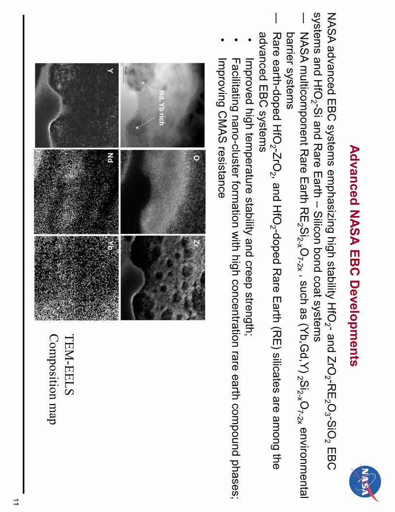
Advanced NASA
EBC
Developm
ents
NA
SA
advanced EB
C system
s emphasizing high stability H
fO2 -and ZrO
2 -RE
2 O3 -S
iO2 E
BC
system
s and HfO
2 -Si and R
are Earth – S
ilicon bond coat systems
― N
AS
A m
ulticomponent R
are Earth R
E2 S
i2-x O7-2x , such as (Yb,G
d,Y) 2 Si2-x O
7-2x environmental
barrier systems
― R
are earth-doped HfO
2 -ZrO2 , and H
fO2 -doped R
are Earth (R
E) silicates are am
ong the advanced E
BC
systems
• Im
proved high temperature stability and creep strength;
• Facilitating nano-cluster form
ation with high concentration rare earth com
pound phases; •
Improving C
MA
S resistance
TEM-EELS
Com
position map
11

NA
SA EB
C B
ond Coat System
s N
AS
A E
BC
System
s •
HfO
2 -RE
2 O3 -S
iO2 /R
E2 S
i2-x O7-2x environm
ental barrier systems
• C
ontrolled silica content and rare earth dopants to improve E
BC
stability, toughness, erosion and C
MA
S resistance
• H
fO2 -S
i based bond coat, controlled oxygen partial pressure •
Advanced rare earth-S
i composition system
s for 2700°F+ long-term applications
• E
arly RE
2 O3 -S
iO2 -A
l2 O3 or YA
G S
ystems
• D
evelop prime-reliant com
posite EB
C-C
MC
s, HfS
iRE
(CN
) systems
Bond coat systems for prime reliant EBCs; capable of self-healing %
1212

Developm
ent of Advanced H
fO2 -Si B
ond Coats
– C
oating architecture and HfO
2 contents can be effectively controlled and optim
ized –
Si:H
f atomic ratio preferably 2:1 – 1:1
– R
eported Spinodal decom
position of hafnium-silicate system
s
100 100
Silicon concentration, at%
80 80
60 60
40 40
20 20
Si
O
Oxygen concentration, at% 0
0 0
1020
3040
50 H
afnium concentration, at%
13

Microstructures of Furnace C
yclic Tested GdYbSi(O
) EBC
System
s —
C
yclic tested cross-sections of PV
D processed YbG
dSi(O
) bond coat —
S
elf-grown rare earth silicate E
BC
s and with som
e RE
-containing SiO
2 rich phase separations —
R
elatively good coating adhesion and cyclic durability
1500°C, in air, 500, 1 h cycles /
B
A
-C
omplex coating architectures
after the testing -
Designed w
ith EB
C like
compositions – Self-grow
n E
BC
s
Com
position (mol%
) spectrum A
rea #1 SiO
2 67.98
Gd2O
3 11.95
Yb2O
3 20.07
Com
position (mol%
) spectrum A
rea #2 SiO
2 66.03
A
B Gd2O
3 10.07
Yb2O
3 23.9
14

Microstructures of C
yclic Tested GdYbSi(O
) EBC
System
s-Continued
—
Cyclic tested cross-sections of P
VD
processed YbGdS
i(O) bond coat
—
Self-grow
n rare earth silicate EB
Cs and w
ith some R
E-containing S
iO2 rich phase separations
—
Interface growth instability
1500°C, in air, 500, 1 hr cycles
Outlined area
SpotC
omposition (m
ol%)
SiO2
66.72 G
d2O3
8.62 Y
b2O3
24.66
Com
position (mol%
) SiO
2 96.15
Gd2O
3 1.2
Yb2O
3 2.64
15

Advanced EBC
developments – Som
e Hybrid Air-Plasm
a Spray/EB
-PVD Turbine C
ombustor EB
C System
s and Qualification
ND
2 N
D6
ND
7
Surface spallation
Tests •
Achieved low
thermal conductivity ranging from
1.0 -1.7 W
/m-K
•
Dem
onstrated high pressure environmental
stability at 2600-2650°F, 12-20 atm. in the high
pressure burner rig •
Surface recession or m
icro-spallation for less tougher coating system
s
2” diameter N
D3
EB
C/S
iC/S
iC
specimen after
testing in the high pressure burner rig A
t 2600°F+, 200 m
/s
High pressure burner rig tested new
ND
series Hybrid
EBC
systems coated on 2” diam
eter Gen II P
repreg S
iC/S
iC C
MC
s 16

Erosion and Impact A
spects: Early Mach 0.3 B
allistic Im
pact Tests of HfO
2 -Si Bond C
oat EBC
Systems
─
Advanced high toughness E
BC
s tested with com
parable performance of best TB
Cs
ND
2 ─
M
ore advanced EB
C com
positions currently also in developments
Spalled area, cm2
Projectile velocity, m/s
150 200 250 300 350
400 450
1.6 7Y
SZ and low k TB
Cs ZrR
ETT A
TES series N
D2
ND
3N
D6
ND
7SU
P-ERA
7.4 EBC
t'-ZrO
2/NA
SA EB
C
Cubic low
k ZrO2 k-N
ASA
EBC
500
NA
SA SU
P-ERA
7.4 EBC
ND
6 NA
SA EB
C
t'/ NA
SA EB
CN
D7 N
ASA
EBC Spalled
ND
3
ND
6 EBC
ND
7 EBC
1.4
1.2
1.0
0.8
0.6
ND
3
ND
6
SUP7.1A
EBC
0.4
0.2 SU
P-ERA
7.4 0.00.0
0.5 1.0
1.5 2.0
2.5 Energy, J
SUP-ER
A 7.4 EB
C N
D7
17

Advanced EB
C C
oating Material Strength Evaluations
– H
igh strength EB
Cs and bond coats are critical for prim
e-reliant designs •
Multicom
ponent EB
Cs and first-generation H
fO2 -S
i bond coat achieved 150-200 MP
a strength at high tem
perature (1400°C+)
• M
ulticomponent silicates show
ed improved high tem
perature strengths compared to
baseline yttrium and ytterbium
silicates •
High strength and high toughness are critical for erosion and fatigue cracking
669-Yb
2 Si 2 O 7
660-Y 2 Si2 O
7
659-Yb
2 SiO5
Strength, MPa
resistance 350
300
250
200
646-Specially toughened t' like HfO
2 648-EB
C B
ond Coat C
onstituent 658-A
E9932 660-Y
2Si2O7
657-Zr-RE silicate (M
ulti-component)
669-Yb2Si2O
7 670-R
are Earth Disilicate (M
ulti-component)
681-HfO
2-Si 696-EB
C B
ond Coat C
onstituent 150
100
500 0 200
400 600
800 1000
1200 1400
1600 Tem
perature, °CFlexure strengths of selected E
BC
materials
18

High H
eat Flux and CM
AS Resistance are Ensured by Advanced
High M
elting Point Coating, and M
ulti-Com
ponent Com
positions –
Non stoichiom
etric characteristics of the CM
AS
– rare earth silicate reacted apatite phases – up to 200 h testing
– D
ifference in partitioning of ytterbium vs. yttrium
in apatite •
Average AE
O/R
E2 O
3 ratio ~ 0.68 for ytterbium silicate – C
MA
S system
•
Average AE
O/R
E2 O
3 ratio ~ 0.22 for yttrium silicate – C
MA
S system
Ahlborg and Zhu, Surface &
Coatings Technology 237 (2013) 79–87.
RE
2 O3
SiO2
AEO
Com
position in apatite (100 hr):
Yttrium
Silicate EBC
Com
position in apatite (100 hr):
Ytterbium
Silicate EBC
19

High H
eat Flux and CM
AS Resistance Tests of Advanced EB
C
Systems
– M
ulticomponent rare earth silicate E
BC
showed im
proved performance
– S
ilicate based coatings still sensitive to CM
AS
concentrations (estimated
variation between average C
MA
S at 25 m
g/cm2 to m
ore concentrated region C
MA
S at 75 m
g/cm2)
– S
ome coating dam
age occurred for EB
Cs in JE
TS tests at higher C
MA
S loading
regions
Initially infiltrated /
Temperature, C
25h / 50h
100h 4450 Cycles
2000 C
MA
S tempertaure
Tsurface, C
Tback, C
1500
1000
500
Turbine vane EB
C, C
MA
S JE
TS
0 0 50
100 150
tests (100 h) Tim
e, hours
Laser rig test of advanced coating systems
20

Thermal G
radient Tensile Creep R
upture Testing of Advanced Turbine Environm
ental Barrier C
oating SiC/SiC
CM
Cs
─
Advanced high stability m
ulti-component hafnia-rare earth silicate based turbine
environmental barrier coatings being successfully tested for 1000 hr creep rupture
─
EB
C-C
MC
creep, fatigue and environmental interaction is being em
phasized
EB
C coated tensile specim
en
Laser beam
delivery optic system
C
ooling show
er head
Total strain, %
1.5 G
en II CMC w
ith advanced EBC Tested at 15 ksi &
heat flux Tsurface = 2700°F
Gen II CM
C-uncoated Tinterface= 2500°F
1.0 2400 F
TCMC back=2320°F
Tested at 20 ksi, 1316°C Typical prem
ature failure
Gen II CM
C with advanced EBC
tested 20 ksi, 1316°C 2400 F
0.5 G
en II CMC w
ith advanced EBC Tested at 20 ksi &
heat fluxjets
Tsurface = 2750ºF G
en II CMC uncoated
Tinterface = 2450ºF H
igh tem
perature 2400 F
Tested at 15 ksi, 1316°CTCM
C back = 2250ºC2250 F
0.0 1
extensometer
0 200
400 600
800 1000
1200Test specim
en Tim
e, hours
21

Thermal G
radient Fatigue-Creep Testing of A
dvanced Turbine Environm
ental Barrier C
oating SiC/SiC
CM
Cs -
Continued
Advanced environm
ental barrier coatings – Prepreg C
MC
systems dem
onstrated long-term
EB
C-C
MC
system creep rupture capability at stress level up to 20 ksi at T
EBC 2700°F, T
CM
C
interface ~2500°F
The HfO
2 -Si based bond coat show
ed excellent durability in the long term creep tests
EBC
s on Gen II C
MC
after 1000 h fatigue H
ybrid EBC
s on Gen II C
MC
after 1000 h testing
low cycle creep fatigue testing
22

High H
eat Flux Thermom
echanical fatigue Tests of A
dvanced NA
SA EB
C-B
ond Coats System
s on CM
Cs
• Laser H
igh Heat Flux them
omechanical fatigue testing of a H
fO2 -S
i and NA
SA
advanced E
BC
baseline with steam
at 3 Hz, 2600-2700°F, and 69 M
Pa m
aximum
stress with stress
ratio 0.05, completed 500 h testing
• Tsurface = 1500-1600°C
•
T= 1320-1350°C
• H
eat Flux = 170 W/cm
2 3 hz fatigue testing at 10 ksi loading C
ompleted 500 hr testing
Testing proving vital failure m
echanisms in a sim
ulated test environm
ents
• S
pecimen had som
e degradations
EBC
s
EBC
s H
igher Si content HfO
2 -Si
2323

EBC
-CM
C Therm
al Gradient C
reep Rupture and
Delam
ination Modeling
A
n equivalent stress model is established for E
BC
multicrack stress intensity m
odeling: em
phasize creep, thermal gradient and stress rupture interactions
D. Zhu and L. G
hosn, “Creep, Fatigue and Fracture B
ehavior of Environmental B
arrier Coating and SiC
-SiC C
eramic M
atrix Com
posite Systems: The R
ole of Environment Effects”, in
The 11th International C
onference on Ceram
ic Materials and C
omponents for E
nergy and Environm
ental Applications, V
ancouver, British C
olumbia, C
anada, June 15-19, 2015.
B
enchmark failure m
odes established in EB
C system
s, strong bond coat beneficial
Finite Elem
ent Analysis (FE
A) M
odeling
24

EBC
-CM
C Therm
al Gradient C
reep Rupture and
Delam
ination Modeling – B
ond Coat Stiffness Effect
─ A
dvanced EB
Cs designed w
ith higher strength and stiffness to improve
creep, fatigue, and cyclic durability
D. Zhu and L. G
hosn, “The Developm
ent of Environmental B
arrier Coating System
s for SiC-SiC
Ceram
ic Matrix C
omposites: Environm
ent Effects on the Creep and Fatigue R
esistance”, in A
erospace Coatings C
onference & E
xposition 2014: Developm
ent and Manufacturing T
rend for the 21st Century, H
artford, CT, U
SA, O
ctober 8, 2014
25

Fatigue Tests of Advanced RESi B
ond Coats and EB
C System
s -
AP
S and P
VD
processed 2700°F bond coats on CM
C: focus on fatigue testing at
temperatures 2400-2700°F
-E
BC
bond coats critical to prime-reliant coating system
designs Fatigue Tested
002_#17A
ir Plasm
a Sprayed A
PS
YSi+H
f-RE
Silicate 1316°C
, 10ksi, 1000 h fatigue (3 Hz, R
=0.05)
1169 h fatigue (3 Hz, R
=0.05) on GE
E
B-P
VD
HfR
E2 S
i2-x O7-x E
BC
/GdYbS
i(O) bond
Prepreg S
iC/S
iCcoat on C
VI-M
I SiC
/SiC
(with C
MA
S)
1537°C, 10ksi, 300 h fatigue (3 H
z, R=0.05)
EB
-PV
D R
E2 S
i2-x O7-x E
BC
/HfO
2 -Si bond coat on 3D
C
VI+PIP
SiC
/SiC
1482°C, 10ksi, S
PLC
F fatigue at 3 H
z, R=0.5 (300 h furnace tested, 500 h in laser
thermal gradient
Creep and Fatigue Test w
ith CM
AS
PV
D G
dYSi(O
) coated on Hyper Them
12C-461-
PV
D G
dYbSi(O
) bond coat,1316°C, 15ksi,
EB
C B
ond Coat series on R
oyce Royce H
TC
CV
I-MI S
iC/S
iC (w
ith CM
AS
) 1400°C
,at 10 ksi, 400 h
26

EBC
-CM
C Turbine Elem
ent Fatigue Testing
• Testing approaches developed for E
BC
-CM
C trailing edge therm
omechanical testing
• H
igh heat flux capability to simulate required high therm
al gradients and more com
plextem
perature distributions in a turbine engine•
Mechanical loading to sim
ulate the high pressure turbine airfoil pressure (ballooning) effects•
EB
C-C
MC
durability being evaluated, planned incorporation of stream jet environm
ents
Maxim
um P
rincipal Strain vs. A
irfoil Internal Pressure
EB
C coated Trailing E
dge (TE)
“wedge” testing in high heat flux and
0.00
0.02
0.04
0.06
0.08
0.10
0.12
0.14
0.16
0.18
0.20
0.22
0.24
0.26
0.28
0.30
0 20
40 60
80 100
120 140
160 180
Maxium Principal Strain (%)
Internal Pressure (psi)
mechanical fatigue loading
Modeled testing /
27

Strains Measurem
ents for Coated A
irfoil Trailing Edge Subelem
ents at High Loads
-The results show
ed complex coating cycling behavior, and out of phase strain cycles
also on the EB
C coated sides
-P
ossibly changed neutral axes of the deflections of the CM
C thin and thick w
alls -
Challenges for m
odeling along with therm
al in-phase and out-phase loading
28

Load, N
SiC/SiC
Turbine Airfoil Trailing Edge Tests
-S
ubelement w
edge testing and high temperature tests, aim
ing at understanding the C
MC
and EB
C degradation
MI S
iC/S
iC C
MC
2000
TEST_HT
DAM
AGE m
odel TEST_H
T
00.00 0.05
0.10 0.15
0.20 0.25
0.30 0.35
Displacements, m
m
4000
5000
6000
7000
8000
9000
TEST DAM
AGE m
odel
Von Mises
Stress Plot
4000 CV
I SiC
/SiC
CM
C
30003000
Load, N
No reduction 2000
1000 Subelem
ent Load-Displacem
ent curve – P
repreg MI C
MC
trailing edge
0-0.1 -0.1 0.0 0.1 0.1 0.2 0.2 0.3 0.3 0.4 0.4 0.4 0.5 0.5 0.6
Displacem
ents, mm
A
dvanced EB
C coated vanes tests
Subelem
ent Load-Displacem
ent curve – CV
I CM
C trailing edge
29
1000

Summ
ary •
Prime-R
eliant and durable EBC
s are critical to emerging SiC
/SiC C
MC
Hot-Section
component technologies
─
The EB
C developm
ent built on a solid foundation from past experience, evolved w
ith the current state of the art com
positions with higher tem
perature capabilities and stabilities •
Multicom
ponent EB
C oxide-doped silicates show
ed promise w
ith improved
stabilities, strength and toughness, and durability in various tests •
HfO
2 -Si and R
E-S
i bond coats, along with R
ES
iHfC
N potentially for realizing prim
e-reliant E
BC
-designs •
Advanced testing help scale-up for com
ponents and EV
C-C
MC
modeling
Current em
phases and future paths: ─
B
etter understanding of the coating failure mechanism
s, and helping develop coating property databases and validate life m
odels, aiming at m
ore robust EB
C-C
MC
designs ─
C
ontinue to focus on coating composition and processing im
provements, sim
ulated engine environm
ent testing and performance m
odeling ─
D
esign high strength, strain tolerant, CM
AS
resistant top coat; and dense, low diffusion
and high toughness EB
C and bond coats
─
Self-repairing and/or self-grow
ing of slow grow
th adherent EB
C coatings, m
inimizing
silica separation
30

A
cknowledgem
ents •
The work w
as supported by NASA
Fundamental Aeronautics Program
(FAP) Transform
ational Tools and Technologies (TTT) Project
In particular, the contributions from the follow
ing:
NA
SA
EBC-C
MC
Team, In particular, Jim
DiC
arlo, Jim Sm
ialek, Dennis Fox, Bryan H
arder, Robert A
. Miller,
Janet Hurst, M
artha Jaskowiak, R
am B
hatt, Mike H
albig, Valerie Wiesner, N
ate Jacobson, Narottam
B
ansal, Francisco Sola-Lopez, and S
erene Farmer, (N
AS
A G
RC
)
Collaborators include:
Sulzer M
etco (US
) -Mitch D
orfman; C
his Dam
bra D
irected Vapor Technologies, International – Derek H
ass and Balvinder G
ogia P
raxair Surface Technologies – John A
nderson and Li Li S
outhwest R
esearch Institute – Ronghua W
ei (PV
D coating processing)
in supporting the coating processing
31