clearview 4:2 h.264 to mpeg-2 hd transcoder
TRANSCRIPT

Stock # Model Name Description
6559 Clearview 4:2 H.264 to MPEG-2 HD Transcoder; 24 Channels
All Rights Reserved. Specifications subject to change without notice. All trademarks are property of their respective owners.
H.264 to MPEG-2 HD Transcoderfor up to 24 SPTS Programs
© Blonder Tongue Labs, Inc. ISO 9001:2015 Certified P/N: 651245300A | Rev: 070921
Clearview 4:2User Manual

2 Clearview 4:2User Manual
Returning Product for Repair (or Credit)A Return Material Authorization (RMA) Number is required on all products returned to Blonder Tongue, regardless if the product is being returned for repair or credit. Before returning product, please contact the Blonder Tongue Service Department at 1-800-523-6049, Ext. 4256 or visit our website: www.blondertongue.com for further information.
Cross-Reference & Hyperlinking UsageThis guide makes use of hyperlinks for the Table of Contents, some cross-reference linking between sections, and external hyperlinking to web addresses. This has been done to assist the reader in finding the information they are seeking in a much quicker way. In addition to hyperlinking, the Table of Contents also makes use of the bookmarking feature present in the Adobe Reader application.
Product and Documentation UpdatesDownload the latest User Manual (PDF) by visiting our website. Navigate to the product page by entering the full Model Name or Stock Number in the search field. Upon reaching the product page, the “User Manual” download link will be located beneath the product image. Firmware Updates are available under “Tech Support” in the “Resources” section of the website. General instructions for the FTP site, as well as updating your firmware, are provided on this page.
We recommend that you write the following information in the spaces provided below.
The information contained herein is subject to change without notice. Revisions may be issued to advise of such changes and/or additions.Correspondence regarding this publication should be addressed directly to:
Blonder Tongue Laboratories, Inc.One Jake Brown RoadOld Bridge, NJ 08857 USA
Document Number: 651245300APrinted in the United States of America.All product names, trade names, or corporate names mentioned in this document are acknowledged to be the proprietary property of the registered owners.
This product incorporates copyright protection technology that is protected by U.S. patents and other intellectual property rights. Reverse engineering or disassembly is prohibited.
Purchase Location Name:
Purchase Location Telephone Number:
Clearview 4:2 Serial Number(s):

3Clearview 4:2User Manual
Table of ContentsSECTION 1 – GENERAL & SAFETY INSTRUCTIONS ....................................................................................................... 4
SECTION 2 – PRODUCT SUMMARY .............................................................................................................................. 52.1 PRODUCT APPLICATION & FEATURES ................................................................................................................... 52.2 HARDWARE DESCRIPTION ..................................................................................................................................... 62.3 PRODUCT SPECIFICATIONS .................................................................................................................................... 7
SECTION 3 – INSTALLATION & POWER-UP .................................................................................................................. 83.1 BEFORE YOU BEGIN ................................................................................................................................................ 83.2 UNPACKING ............................................................................................................................................................. 83.3 INSTALLATION AND POWER-UP ............................................................................................................................ 8
SECTION 4 – CONNECTING TO A PC/LAPTOP .............................................................................................................. 94.1 ETHERNET ACCESS .................................................................................................................................................. 94.2 ACCESSING THE USER INTERFACE VIA THE WEB BROWSER .............................................................................. 9
SECTION 5 – BASIC CONFIGURATION ......................................................................................................................... 115.1 “STATUS” SCREEN ................................................................................................................................................... 115.2 “SYSTEM” SCREEN.................................................................................................................................................. 125.3 “TIME” SCREEN ...................................................................................................................................................... 145.4 “ADMIN” SCREEN ................................................................................................................................................... 16
SECTION 6 – TRANSCODERS ........................................................................................................................................ 176.1 “TRANSCODERS: STATUS” SCREEN ....................................................................................................................... 176.2 “TRANSCODERS: SETTINGS” SCREEN .................................................................................................................. 17
SECTION 7 – SYSTEM UPDATES AND LOG .................................................................................................................. 207.1 “FIRMWARE UPDATE” SCREEN ............................................................................................................................. 207.2 “LOG” SCREEN ........................................................................................................................................................ 21
SECTION 8 – TROUBLESHOOTING ............................................................................................................................... 228.1 VERIFY THE COM3000 IS AUTHORIZED CORRECTLY ........................................................................................... 22
SECTION 9 – TECHNICAL SUPPORT ............................................................................................................................. 25
APPENDIX A – NON-STANDARD NETWORK CONFIGURATION .................................................................................. 26

4 Clearview 4:2User Manual
å Elevated Operating Ambient - If installed in a closed or multi-unit rack assembly, the operating ambient temperature of the rack environment may be greater than room ambient. Therefore, consideration should be given to installing the equipment in an environment compatible with the maximum ambient temperature per Section 2.3.
å Reduced Air Flow - Installation of the equipment in a rack should be such that the amount of air flow required for safe operation of the equipment is not compromised.
å Mechanical Loading - Mounting of the equipment in the rack should be such that a hazardous condition is not achieved due to uneven mechanical loading.
å Circuit Overloading - Consideration should be given to the connection of the equipment to the supply circuit and the effect that overloading of the circuits might have on overcurrent protection and supply wiring. Appropriate consideration of equipment nameplate ratings should be used when addressing this concern.
å Reliable Earthing - Reliable earthing of rack-mounted equipment should be maintained. Particular attention should be given to supply connections other than direct connections to the branch circuit (e.g. use of power strips).
å Read all safety and operating instructions before you operate the unit. å Retain all safety and operating instructions for future reference. å Heed all warnings on the unit and in the safety and operating instructions. å Follow all installation, operating, and use instructions. å Unplug the unit from the AC power outlet before cleaning. Use only a damp
cloth for cleaning the exterior of the unit. å Do not use accessories or attachments not recommended by Blonder Tongue,
as they may cause hazards, and will void the warranty. å Do not operate the unit in high-humidity areas, or expose it to water or
moisture. å Do not place the unit on an unstable cart, stand, tripod, bracket, or table. The
unit may fall, causing serious personal injury and damage to the unit. Install the unit only in a mounting rack designed for 19” rack-mounted equipment.
å Do not block or cover slots and openings in the unit. These are provided for ventilation and protection from overheating. Never place the unit near or over a radiator or heat register. Do not place the unit in an enclosure such as a cabinet without proper ventilation. Do not mount equipment in the rack space directly above or below the unit.
å Operate the unit using only the type of power source indicated on the marking label. Unplug the unit power cord by gripping the plug, not the cord.
å The unit is equipped with a three-wire ground-type plug. This plug will fit only into a ground-type power outlet. If you are unable to insert the plug into the outlet, contact an electrician to replace the outlet. Do not defeat the safety purpose of the ground-type plug.
å Route power supply cords so that they are not likely to be walked on or pinched by items placed upon or against them. Pay particular attention to cords at plugs, convenience receptacles, and the point where they exit from the unit.
WARNING: TO PREVENT FIRE OR SHOCK HAZARD, DO NOT EXPOSE THIS UNIT TO RAIN OR MOISTURE
NOTE TO CATV SYSTEM INSTALLERThis reminder is provided to call the CATV System Installer’s attention to Article 820-40 of the NEC that provides guidelines for proper grounding and, in particular, specifies that the cable ground shall be connected to the grounding system of the building, as close to the point of cable entry as practical.
TO REDUCE THE RISK OF ELECTRICAL SHOCK, DO NOT REMOVE COVER FROM THIS UNIT.
NO USER-SERVICEABLE PARTS INSIDE. REFER SERVICING TO QUALIFIED SERVICE PERSONNEL.
Section 1 – General & Safety Instructions
The STOP sign symbol is intended to alert you to the presence of REQUIRED operating and maintenance (servicing) instructions that if not followed, may result in product failure or destruction.
The YIELD sign symbol is intended to alert you to the presence of RECOMMENDED operating and maintenance (servicing) instructions.
The LIGHTNING flash symbol is intended to alert you to the presence of uninsulated “dangerous voltage” within the product's enclosure that may be of sufficient magnitude to constitute a risk of electrical shock.
You should always follow these Instructions to help ensure Against injury to yourself and damage to your equipment.
å Be sure that the outdoor components of the antenna system are grounded in accordance with local, federal, and National Electrical Code (NEC) requirements. Pay special attention to NEC Sections 810 and 820. See the example shown in the following diagram:
å We strongly recommend using an outlet that contains surge suppression or ground fault protection. For added protection during a lightning storm, or when the unit is left unattended and unused for long periods of time, unplug it from the wall outlet and disconnect the lines between the unit and the antenna. This will prevent damage caused by lightning or power line surges.
å Do not locate the antenna near overhead power lines or other electric light or power circuits, or where it can fall into such power lines or circuits. When installing the antenna, take extreme care to avoid touching such power lines or circuits, as contact with them can be fatal.
å Do not overload wall outlets or extension cords, as this can result in a risk of fire or electrical shock.
å Never insert objects of any kind into the unit through openings, as the objects may touch dangerous voltage points or short out parts. This could cause fire or electrical shock.
å Do not attempt to service the unit yourself, as opening or removing covers may expose you to dangerous voltage and will void the warranty. Refer all servicing to authorized service personnel.
å Unplug the unit from the wall outlet and refer servicing to authorized service personnel whenever the following occurs:
o The power supply cord or plug is damaged; o Liquid has been spilled, or objects have fallen into the unit; o The unit has been exposed to rain or water; o The unit has been dropped or the chassis has been damaged; o The unit exhibits a distinct change in performance.
å When replacement parts are required, ensure that the service technician uses replacement parts specified by Blonder Tongue. Unauthorized substitutions may damage the unit or cause electrical shock or fire, and will void the warranty.
å Upon completion of any service or repair to the unit, ask the service technician to perform safety checks to ensure that the unit is in proper operating condition.
5Clearview 4:2User Manual
Section 2 – Product Summary
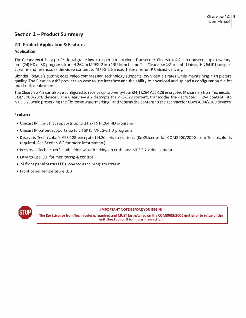
2.1 Product Application & FeaturesApplication:
The Clearview 4:2 is a professional grade low-cost-per-stream video Transcoder. Clearview 4:2 can transcode up to twenty-four (24) HD or SD programs from H.264 to MPEG-2 in a 1RU form factor. The Clearview 4:2 accepts Unicast H.264 IP transport streams and re-encodes the video content to MPEG-2 transport streams for IP Unicast delivery.Blonder Tongue’s cutting edge video compression technology supports low video bit rates while maintaining high picture quality. The Clearview 4:2 provides an easy to use interface and the ability to download and upload a configuration file for multi-unit deployments.The Clearview 4:2 can also be configured to receive up to twenty-four (24) H.264 AES-128 encrypted IP channels from Technicolor COM3000/2000 devices. The Clearview 4:2 decrypts the AES-128 content, transcodes the decrypted H.264 content into MPEG-2, while preserving the “forensic watermarking” and returns the content to the Technicolor COM3000/2000 devices.
Features:
• Unicast IP input that supports up to 24 SPTS H.264 HD programs
• Unicast IP output supports up to 24 SPTS MPEG-2 HD programs
• Decrypts Technicolor’s AES-128 encrypted H.264 video content. (Key2License for COM3000/2000 from Technicolor is required. See Section 6.2 for more information.).
• Preserves Technicolor’s embedded watermarking on outbound MPEG-2 video content
• Easy-to-use GUI for monitoring & control
• 24 front panel Status LEDs, one for each program stream
• Front panel Temperature LED
IMPORTANT NOTE BEFORE YOU BEGIN!The Key2License from Technicolor is required and MUST be installed on the COM3000/2000 unit prior to setup of this
unit. See Section 3 for more information.

6 Clearview 4:2User Manual
2.2 Hardware Description
2 4 5 6
1 3
7 8
Power LED: If the LED is Green, the AC power is detected. If the LED is Off, it will indicate one of the following:(i) AC power is not connected, or(ii) AC power is connected but the power supply is defective. Unit must be sent to factory for repairs.
Temperature LED:• Solid Red = Unit temperature is critically high.• Solid Amber = Unit temperature is high.• Solid Green = Unit temperature is normal.
IP Video: RJ45 for 1000Base-T Ethernet (GigE) interface; used for IP Video Input and Output.
Control: RJ45 connector for 1000Base-T Ethernet (GigE) Ethernet interface for monitoring and configuring the unit via standard web browser. Only a static IP address can be assigned to this interface. (Factory Default: "172.16.70.1")
IP Reset: When pushed and held for 5 seconds, temporarily resets the IP address, Usernames, and Passwords to Factory Default. Activation is indicated by the Power LED blinking twice. Default values are as follows:
IP address = 172.16.70.1Username = Admin (case-sensitive)Password = pass (case-sensitive)
NOTE: Resetting power will revert IP and login credentials back to what has been configured by the user. The effects of activating the IP Reset feature are temporary and only last until the unit is power cycled.
Status LEDs # 1 through 24:• Off = Transcode channel is not enabled.• Solid Green = Transcode channel is configured and currently transcoding without issue.• Solid Red = Transcode channel is experiencing an error or has failed. See log for details.
1
2
3
4
5
6
Input Power Assembly and Fuse: IEC 14 power inlet plug – rated 110-230 VAC; 0.9/0.45 A; 60/50 Hz; equipped with Slo-Blo, 3.0A, 250 V Fuse. The operation of the power assembly can be monitored through the User Interface.
Chassis Fans: Fans used to cool the unit. The operation of these fans can be monitored through the User Interface.
7
8
7Clearview 4:2User Manual
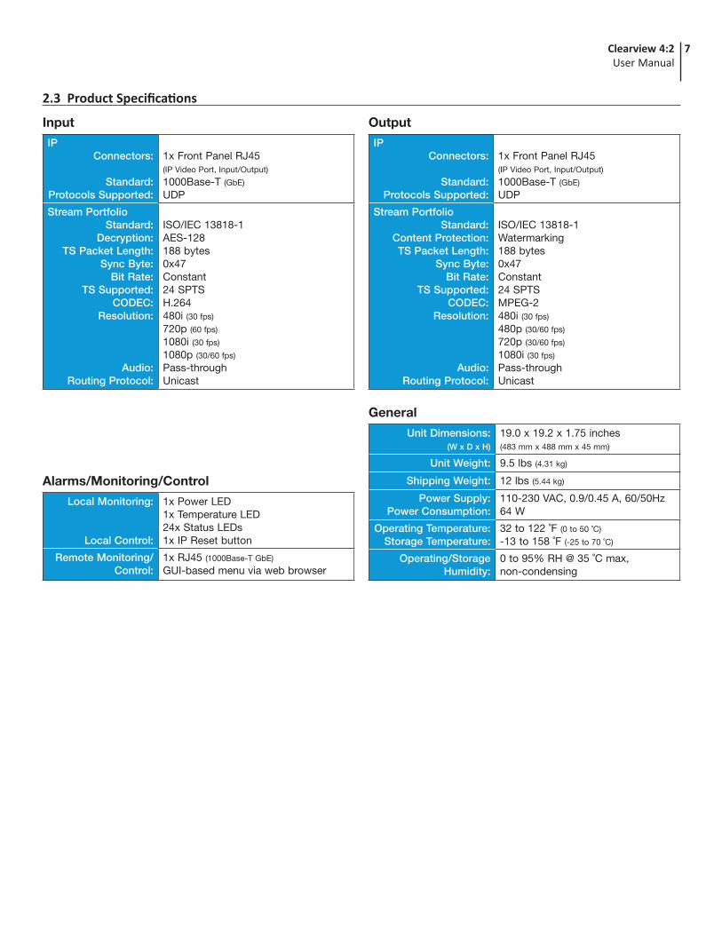
2.3 Product Specifications
Input
IPConnectors:
Standard:Protocols Supported:
1x Front Panel RJ45 (IP Video Port, Input/Output)
1000Base-T (GbE)
UDP
Stream PortfolioStandard:
Decryption:TS Packet Length:
Sync Byte:Bit Rate:
TS Supported:CODEC:
Resolution:
Audio:Routing Protocol:
ISO/IEC 13818-1AES-128188 bytes0x47Constant24 SPTSH.264480i (30 fps)
720p (60 fps)
1080i (30 fps)
1080p (30/60 fps)
Pass-throughUnicast
IPConnectors:
Standard:Protocols Supported:
1x Front Panel RJ45 (IP Video Port, Input/Output)
1000Base-T (GbE)
UDP
Stream PortfolioStandard:
Content Protection:TS Packet Length:
Sync Byte:Bit Rate:
TS Supported:CODEC:
Resolution:
Audio:Routing Protocol:
ISO/IEC 13818-1Watermarking188 bytes0x47Constant24 SPTSMPEG-2480i (30 fps)
480p (30/60 fps)
720p (30/60 fps)
1080i (30 fps)
Pass-throughUnicast
Output
Alarms/Monitoring/Control
Local Monitoring:
Local Control:
1x Power LED1x Temperature LED24x Status LEDs1x IP Reset button
Remote Monitoring/Control:
1x RJ45 (1000Base-T GbE)
GUI-based menu via web browser
General
Unit Dimensions: (W x D x H)
19.0 x 19.2 x 1.75 inches (483 mm x 488 mm x 45 mm)
Unit Weight: 9.5 lbs (4.31 kg)
Shipping Weight: 12 lbs (5.44 kg)
Power Supply:Power Consumption:
110-230 VAC, 0.9/0.45 A, 60/50Hz64 W
Operating Temperature:Storage Temperature:
32 to 122 ˚F (0 to 50 ˚C)
-13 to 158 ˚F (-25 to 70 ˚C)
Operating/Storage Humidity:
0 to 95% RH @ 35 ˚C max, non-condensing

8 Clearview 4:2User Manual
To power the unit up, connect the IEC line cord to the input power receptacle on the rear panel. Then connect the other end to a 120 VAC power outlet. The input power receptacle is equipped with a fuse-holder and fuse (SLO-BLO, 3.0 Amp, 250V).
3.3 Installation and Power-UpThe Clearview 4:2 is designed to be installed in a standard 19-inch (483 mm) rack (EIA 310-D, IEC 60297, and DIN 41494 SC48D).
To install, secure the unit's front panel to the rack by inserting four (4) machine screws, with cup washers, through the four (4) mounting holes in the front panel. A 1RU open space is recommended above the unit for ventilation.
1
2
For safe and reliable operation, the ground pin of the power cord must be grounded properly.
DO NOT BLOCK THE UNIT'S AIR INTAKE OR AIR DISCHARGE OPENINGS.Unit performance will be degraded without proper ventilation.
Excessive heat will shorten the life of the unit.
Section 3 – Installation & Power-up
3.2 UnpackingYou will find the following Items in the box:
• Clearview 4:2 (QTY=1)
• Power Cord with IEC C13 line socket and 3-pin Type B NEMA 5 plug (QTY=1)
The “Key2License” settings (Figures 6.2e) are shown for reference and convenience. See your COM3000/2000 manual for more information.
Browser: The user must first upload the Key2License file to the TFTP server from their local machine.
Software Upgrade: Once the file is on the server, the user can then do the following:
1. Set the “Usage” to “4 = License”
2. Enter the “Server_IP_Address”
3. Set the “Mode” to “0 = TFTP”
Figure 6.2e - COM3000 - Key2License Setup
1
2
1
2
3.1 Before You Begin
The Key2License from Technicolor is required and MUST be installed on the COM3000/2000 prior to installation and setup of this unit. See below for more information.

9Clearview 4:2User Manual
The following steps explain how to do this for a computer with Windows 7, Windows 8.x or Windows 10 operating software: (a) On your computer, navigate to the “Network and Sharing Center”. (Note: It can be found using the search box in the Start Menu or for Windows 8.x, the Start Screen)(b) Once open, click on “Change Adapter Settings” on left hand side of the window.(c) Right-click on the “Local Area Connection”, and then click on the “Properties”.(d) A dialog box entitled “Local Area Connection Properties” will appear. In this box, double-click on the “Internet Protocol Version 4 (TCP/IPv4)”.(e) A dialog box entitled ”Internet Protocol Version 4 (TCP/IPv4) Properties” will appear. Select the “Use the following IP address” option and enter the following addresses:
IP address: 172.16.70.2Subnet mask: 255.255.255.0No need to enter a value for the Default Gateway.
Click OK to close the dialog box. Your computer is now ready to communicate with the unit.
Section 4 – Connecting to a PC/Laptop4.1 Ethernet AccessLocal or remote communication with the unit is only possible through a GUI-based menu via web browser (Chrome or Firefox is recommended). Before you can communicate with the unit, you must configure your computer's IP address to be in the same subnet as the units default IP address. To do so, follow these steps:
Connect one end of the Ethernet cable to the “Control” port on the unit front-panel interface. Connect the other end of the Ethernet cable to your computer.
The factory default IP address of the Control port is 172.16.70.1. In order to communicate with the Control port, you must first change your computer's IP address.
1
2
IMPORTANT NOTE ON PORT CONFIGURATIONThe “Control” port and “IP Video” port should not be configured to be within the same IP subnet. The “Control” port and “IP Video” port should also not be physically connected to the same network without proper network
segmentation.It is possible to access the unit's user interface via the “IP Video” port by using the IP address assigned to XC1.
4.2 Accessing the User Interface via the Web BrowserYou must complete the steps described in Section 4.1 before proceeding as follows:
Open a web browser on your computer (Chrome or Firefox is recommended) and enter the following URL address (http://172.16.70.1). The “Login” screen (Figure 4.2a) will appear.
Enter the following case-sensitive factory-default Username and Password and click [LOG IN].
NOTE: When logged in, the user has administrative read and write permissions. Multiple users can log in simultaneously under the following credentials.
Username = Admin (case-sensitive)Password = pass (case-sensitive)
Figure 4.2a - “Login” Screen
1
2

10 Clearview 4:2User Manual
As shown in Figure 4.2b, under the “Page Header” the following Navigation tabs and links will appear:
• Navigation bar (left side): “Status”, “System”, “Time”, “Transcoders: Status”, and “Transcoders: Settings”
• Navigation bar (right side): “Log” and “Firmware Update”
• In addition, in the upper right corner above the navigation, the user can access the “Admin” screen through a link, alongside the [LOG OUT] button.
Each Primary Navigation bar tab is described in the subsequent Sections.
PAGEHEADER{
Figure 4.2b - Page Header and Navigation
Monitoring and configuration of the unit is achieved via a series of web pages as described in the Sections below. The following read-only information is displayed in a “Page Header” at the top of each web page:
Name: displays a user-defined name to make identification easier. See Section 5.2, to configure this setting.
Location: displays a user-defined location to make identification easier. See Section 5.2, to configure this setting.ESN: displays the unit’s serial number.Uptime: displays the time elapsed since the last time the unit was turned on.Version: displays the software version of the unit.
6
7
4.2 Accessing the User Interface via the Web Browser (continued)

11Clearview 4:2User Manual
Section 5 – Basic Configuration5.1 “Status” Screen“Status” (Figure 5.1) is a “read-only” screen which displays the general health of the unit, such as temperature, fan speed and status reporting. The information is provided as a quick way to monitor the system or assist with troubleshooting issues that may arise.
176 °F80 °C
ErrorErrorWarningWarningNormal TemperatureNormal Temperature
185 °F85 °C
Figure 5.1a - Host Temperature Status Range
The “System Status” page has four (4) columns of data for each system component. The data is detailed as follows:
Device: Indicates the following system components:
• Host is the Clearview 4:2 system.
• XC1 - XC12 display information for each transcode pair. These will populate other data as the pairs are set up and enabled. When a numbered transcode pair is not available the row will display as empty.
• Fans displays data for each of the four system fans on the chassis.
1
Status: Indicates a status for each system component being monitored. The following section gives a breakdown of the information given in this column.
2
Temperature: Indicates the following in real-time:
• Host: Temperature the Host unit is currently running at. Temperatures are displayed in both Fahrenheit and Celsius. (Figure 5.1a)
3
Figure 5.1 - “System Status”
32
7
8
1
5
6
4
1

12 Clearview 4:2User Manual
Other Information:Log Messages: The Log Messages sections will show the 10 most recent entries to the system log. For a full view of all messages, please see the Log tab. The user can click on the "Auto-Refresh" checkbox to enable that function. See Section 7.2 for more information on types of messages.
Reference: The reference link under this section points to the Blonder Tongue website.
7
8
Resets the unit back to the Factory defaults. It is always recommended to save the existing configuration file before resetting to the default values.
Downloads the current module configuration file.
Browse and select a Configuration File.
After choosing file, click this to load and apply the configuration file.
2
5
3
4
Command/Control Ethernet SettingsThis section allows the user to back-up and re-load the configuration using the following settings:
Unit Operations SettingsAllows the user to the unit.1
5.2 “System” Screen“System” (Figure 5.2, next page) is a “read and write” screen. The general Ethernet connection and user-defined identification data for the platform can be configured here.
5.1 “Status” Screen (continued)
ErrorErrorWarningWarningNormal TemperatureNormal Temperature
176 °F80 °C
185 °F85 °C
Figure 5.1b - Transcoder Temperature Status Range
448RPM
ErrorError ErrorErrorWarningWarning WarningWarningNormal RangeNormal Range
1794RPM
8970RPM
11213RPM
Figure 5.1c - Fan RPM Status Range
Status - Messages / Information
Host and XC1 - XC12 (Transcoders): Types of messages under status column.
• Ok: indicates the host is working without errors.
• Transcoding...: indicates the XC is actively transcoding. A column for each of the XC pair is shown per row.
4
• XC (1-12): Temperature each module is currently running at. The temperatures are displayed in both Farenheit and Celsius. (Figure 5.1b)
• Fans: Revolutions Per Minute (RPM), rotational speed, of each fan in the chassis. (Figure 5.1c)
NOTE: Listed are three of the most common status messages. Messages shown will give indication of what is occuring within the unit, alongside Log messages, to help with any required troubleshooting.
Fans: Types of messages under status column for each fan.
• Fan Speed: numerically displayed and measured in Revolutions-per-Minute (RPM).
• PWM Duty Cycle: Pulse-Width Modulation (PWM) indicates if the fan is working at 100% speed or lower, by percentage.
5
• Error: indicates that one or more errors have been detected. See the message log below or navigate to the full Log using the menu at the top.

13Clearview 4:2User Manual
IMPORTANT: A reboot is required after applying a configuration file.
Figure 5.2 - “System” Screen - Full View
1
678
912 13
10 11
2 34 5
14
Command/Control Ethernet SettingsUnit Name: a user-defined field to more easily identify the unit by name. The character limit is 64 alphanumeric, however if other character types are used, the display limit is decreased and may truncate.
Unit Location: a user-defined field to more easily identify the unit's location. The character limit is 64 alphanumeric, however if other characters types are used, the display limit is decreased and may truncate.
MAC Address: the Media Access Control (MAC) Address is a read-only field that serves as a unique identifier assigned to the network.
IP Address: the static IP address that is assigned to the unit, allowing the user to access it via the web interface. Pressing the IP reset button temporarily returns unit to factory default of 172.16.70.1.
Subnet Mask: the subnet mask allows the user to access the unit from another network via the web interface. Factory Default is 255.255.255.0 for local subnet.
Default Gateway: the gateway address of unit, allowing the user to access it from another network via the web interface. The gateway address should be in the same subnet as IP Address.
Primary DNS: the primary Domain Name Server (DNS) hosts the controlling zone file, containing all the authoritative information for a domain.
Secondary DNS: the secondary Domain Name Server (DNS) contains read-only copies of the zone file, and gets its info from a primary server in a communication known as a zone transfer.
11
12
13
6
7
8
9
10
5.2 “System” Screen (continued)

14 Clearview 4:2User Manual
5.3 “Time” ScreenThe “Time” tab (Figures 5.3a to 5.3d) is a “read and write” screen. Time settings for the system and the event log are configured here.
Figure 5.3a - “Current Time at Page Load”
12
Current Time at Page Load
Clearview: read-only display of the unit's current date and time, shown in UTC format. The time is adjusted for states, territories and countries that use time change (ie. Eastern Standard Time and Eastern Daylight Time).
Client: read-only display of the current Client, or local browser, date and time, shown in UTC format with time zone. The time is adjusted for states, territories and countries that use time change (ie. Eastern Standard Time and Eastern Daylight Time).
1
2
5.2 “System” Screen (continued)Transcoder Ethernet Settings
This section allows the user to individually configure the network settings for each numbered transcode pair (XC1 to XC12).When using in conjunction with the Technicolor COM3000/2000, the IP address of the transcode pair (XC1 to XC12) MUST correlate with the IP Port address settings on the "Overview" Tab located on the COM3000/2000. (See Section 6.2 for details)
Technicolor recommends starting the IP address range at: 192.168.6.72
14
Remember to click on the “Apply Settings” button to apply the new values/configurations.
Figure 5.3b - “Time Settings”
34
Time Settings
Time Zone: user is able set the time zone, shown in UTC format.
Time: Clicking the button will synchronize the Clearview time to Client time. This requires that the selected time zone and client system time are correct. After synchronization, the Clearview time shown may lead or lag the Client time by a small margin.
3
4
15Clearview 4:2User Manual
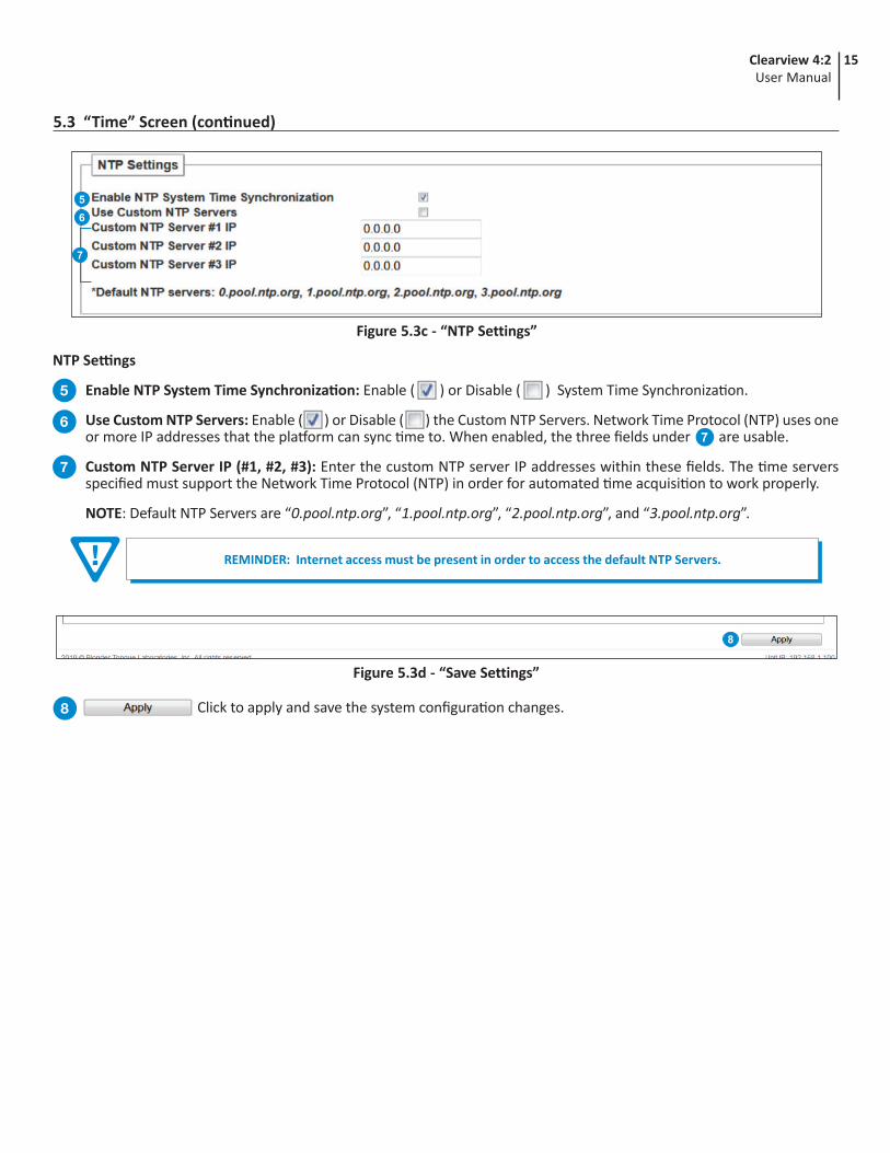
Figure 5.3c - “NTP Settings”
56
7
5.3 “Time” Screen (continued)
Click to apply and save the system configuration changes.8
Figure 5.3d - “Save Settings”
8
NTP Settings
Enable NTP System Time Synchronization: Enable ( ) or Disable ( ) System Time Synchronization.
Use Custom NTP Servers: Enable ( ) or Disable ( ) the Custom NTP Servers. Network Time Protocol (NTP) uses one or more IP addresses that the platform can sync time to. When enabled, the three fields under are usable.
Custom NTP Server IP (#1, #2, #3): Enter the custom NTP server IP addresses within these fields. The time servers specified must support the Network Time Protocol (NTP) in order for automated time acquisition to work properly.
NOTE: Default NTP Servers are “0.pool.ntp.org”, “1.pool.ntp.org”, “2.pool.ntp.org”, and “3.pool.ntp.org”.
5
67
7
REMINDER: Internet access must be present in order to access the default NTP Servers.
16 Clearview 4:2User Manual
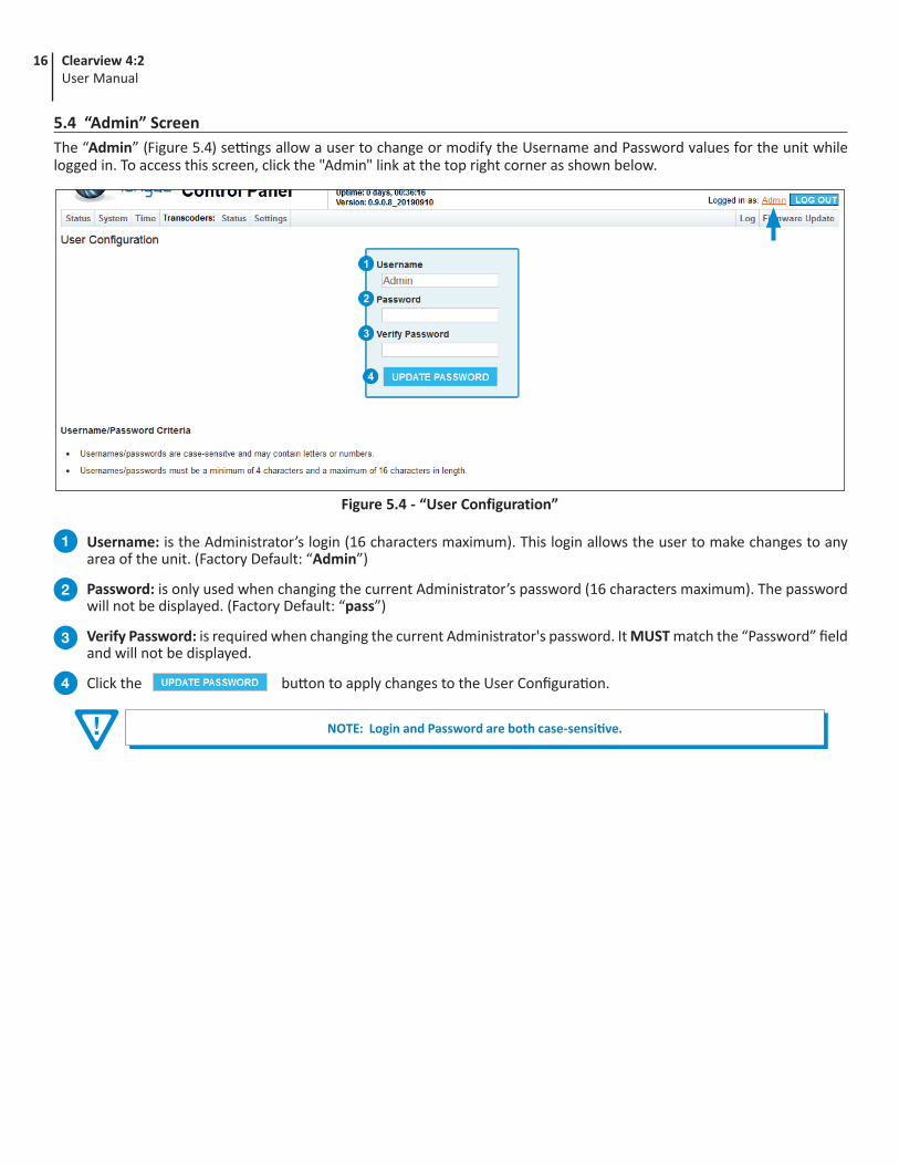
5.4 “Admin” ScreenThe “Admin” (Figure 5.4) settings allow a user to change or modify the Username and Password values for the unit while logged in. To access this screen, click the "Admin" link at the top right corner as shown below.
NOTE: Login and Password are both case-sensitive.
Username: is the Administrator’s login (16 characters maximum). This login allows the user to make changes to any area of the unit. (Factory Default: “Admin”)
Password: is only used when changing the current Administrator’s password (16 characters maximum). The password will not be displayed. (Factory Default: “pass”)
Verify Password: is required when changing the current Administrator's password. It MUST match the “Password” field and will not be displayed.
Click the button to apply changes to the User Configuration.
1
2
3
4
Figure 5.4 - “User Configuration”
1
2
3
4

17Clearview 4:2User Manual
Section 6 – Transcoders6.1 “Transcoders: Status” Screen“Transcoders: Status” (Figure 6.1) is a “read-only” screen which indicates the status of each transcoder. A visual status of the pipeline is also shown on the left side. When hovering over a transcode block, the corresponding status table, to the right, highlights.
Figure 6.1 - “Transcoders: Status” Screen
6.2 “Transcoders: Settings” Screen“Transcoders: Settings” (Figure 6.2a) allows the user to configure each transcoder (XC) pair and displays status information about the input and output streams. A visual status of the pipeline is also shown on the left side. When hovering over a transcode block, the corresponding status table, to the right, highlights.
Figure 6.2a - “Transcoders: Settings” Screen - Full View
IMPORTANT: It is recommended that the user avoid the following incoming port numbers when configuring the Input Stream URI in the transcoder pipeline settings: 50000 - 52000
Pipeline Status States
Light Gray (Red Question Mark): the transcoder has not been detected yet.
Light Gray: the transcoder is disabled.
Dark Gray (Orange Arrow): the transcoder is idle.
Green: the transcoder is active.
Red: the transcode has failed.

18 Clearview 4:2User Manual
Figure 6.2b - “Transcoders: Settings” - Video/Audio Pipeline Settings
1
23456789
5.2 “Transcoders: Settings” Screen (continued)
Pipeline Control: Allows the user to “Enable” or “Disable” the transcode.
Input Stream URI: The user can configure the URI Input stream settings: “Protocol”, “IP”, and “Port”. The user must select the protocol that matches the one used by the receiving equipment. The only available option within this model is: “UDP”. The IP Address and Port MUST correlate with the IP Port address settings on the "Overview" Tab located on the COM3000/2000. (See Figure 6.2c)
Decryption Mode: Sets the Decryption mode for transcoding. The only available mode within this model is: Technicolor COM (AES 128).
Output Resolution: Sets the output video resolution. Options are “480i60”, “480p30”, “480p60”, “720p30”, “720p60”, “1080i60”, “1080p30”.
Output Video Encoding Format: Sets the output video encoding format. The only option available for this model is “MPEG-2”.
Output Video Bitrate: Sets the output video bitrate in Mbps. Options are “2” to “19”, incremented by “0.1” Mbps.
Output Audio Encoding Format: Sets the output audio encoding format. The only option available for this model is “Passthru".
Output Audio Bitrate: Sets the output audio bitrate. The only option available for this model is “Same".
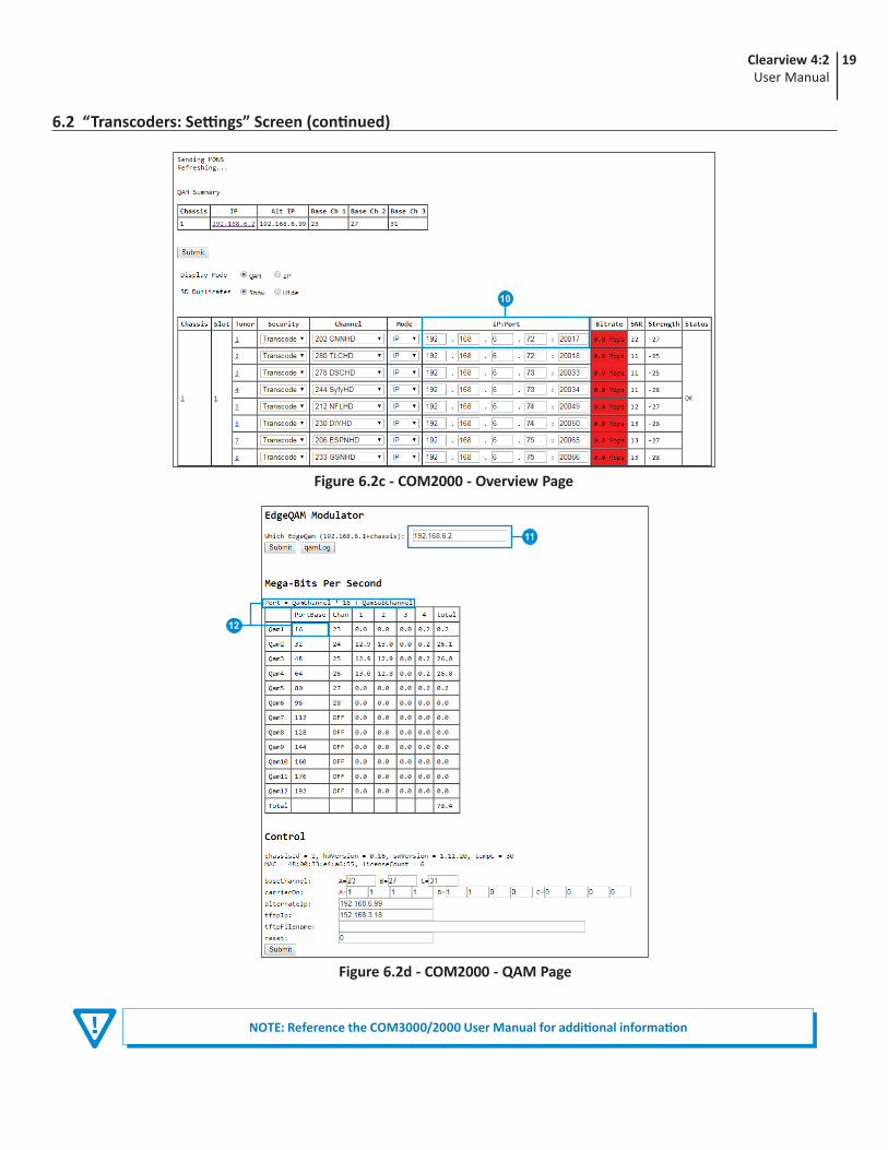
Output Stream URI: The user can configure the URI Output stream settings: “Protocol”, “IP”, and “Port”. The IP can be found on the QAM page of the COM's user interface. The Port number is derived from the “Port” formula on the COM's QAM page. The IP Address MUST match the IP address of the QAM module in the COM3000/2000. (See Figure 6.2d for the QAM)
1
2
3
4
5
6
7
8
9
Channel IP and Port: The Overview page lists the output IP and Port for each channel.
EdgeQAM Modulator: The IP address of the COM unit’s QAM modulator. The Clearview 4:2 transcoder must target this IP in the IP portion of the “Output Stream URI”.
QAM PortBase and Port Formula: This field indicates the base port to use for placing transcoded streams onto a particular RF major/minor channel. Take the PortBase value for the RF channel and add the desired subchannel. For example, to place a transcoded stream onto 23-1, the Output Stream URI port to use would be 16 (PortBase) + 1 (first subchannel on RF 23). Therefore, use port 17.
Port Formula Example: If the COM unit’s first RF channel is configured to be 23 and the CV 4:2’s transcoded output should be placed on 23-1, the CV4:2 transcoder must assigned to port 17 in the Port portion of the “Output Stream URI”. (See Figure 6.2d for the QAM)
“COM2000” settings (Figures 6.2c and 6.2d) are shown for reference. Views or location on the COM3000 unit may or may not differ.
11
12
10
19Clearview 4:2User Manual
6.2 “Transcoders: Settings” Screen (continued)
Figure 6.2c - COM2000 - Overview Page
10
Figure 6.2d - COM2000 - QAM Page
11
12
NOTE: Reference the COM3000/2000 User Manual for additional information

20 Clearview 4:2User Manual
Update the Firmware version by clicking the button. The update status and progress will be displayed under the “Status” columns. Below are the firmware updates as they appear while in-progress (Figure 7.1c) and upon completion (Figure 7.1d).
Note: After clicking the “Update” button, please allow a few seconds for the file to load.
Section 7 – System Updates and Log7.1 “Firmware Update” ScreenThe “Firmware Update” tab (Figures 7.1a to 7.1d) is located on the right side of the main menu. This page allows the user to review the currently installed firmware version and provides a quick and easy way to apply firmware updates.
Once the update progress is complete, the user MUST click the button (as shown on Figure 7.1d) in order to apply and finalize the update.
When firmware updates are complete, the user can remove the loaded file by clicking the button shown on Figure 7.1b next to the “Upload File” button under "Firmware Update Files".
Check “Firmware Version” to ensure you have the latest firmware. To determine if a new firmware update has been released, please go to our website at: (www.blondertongue.com/page/resources/tech-support/firmware-updates/)
Click the “Download Firmware Updates” link and then scroll down to the product folder to access the update file(s).
Note: There is a check of the file name versus the product model ID to eliminate a user inadvertently updating any product models with incorrect files.
1
Under the “Firmware Update Files” section, the user can use and to select and send the update file(s) into the unit. See a view of the file when uploaded to the platform as shown below on Figure 7.1b.
Figure 7.1b - File when uploaded
2
3
4
Figure 7.1c - Update In Progress
3
Figure 7.1d - Completed Update
4
Figure 7.1a - “Firmware Update” Tab
1 3
2
21Clearview 4:2User Manual
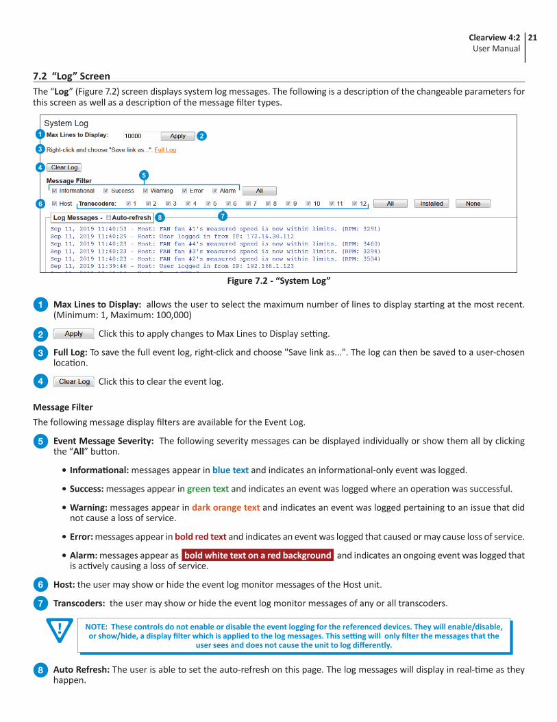
7.2 “Log” ScreenThe “Log” (Figure 7.2) screen displays system log messages. The following is a description of the changeable parameters for this screen as well as a description of the message filter types.
Max Lines to Display: allows the user to select the maximum number of lines to display starting at the most recent. (Minimum: 1, Maximum: 100,000)
Click this to apply changes to Max Lines to Display setting.
Full Log: To save the full event log, right-click and choose "Save link as...". The log can then be saved to a user-chosen location.
Click this to clear the event log.
1
2
3
4
Figure 7.2 - “System Log”
1
3
6
8
4
2
5
7
Auto Refresh: The user is able to set the auto-refresh on this page. The log messages will display in real-time as they happen.
Message FilterThe following message display filters are available for the Event Log.
Event Message Severity: The following severity messages can be displayed individually or show them all by clicking the “All” button.
• Informational: messages appear in blue text and indicates an informational-only event was logged.
• Success: messages appear in green text and indicates an event was logged where an operation was successful.
• Warning: messages appear in dark orange text and indicates an event was logged pertaining to an issue that did not cause a loss of service.
• Error: messages appear in bold red text and indicates an event was logged that caused or may cause loss of service.
• Alarm: messages appear as bold white text on a red background and indicates an ongoing event was logged that is actively causing a loss of service.
Host: the user may show or hide the event log monitor messages of the Host unit.
Transcoders: the user may show or hide the event log monitor messages of any or all transcoders.
5
6
7
8
NOTE: These controls do not enable or disable the event logging for the referenced devices. They will enable/disable, or show/hide, a display filter which is applied to the log messages. This setting will only filter the messages that the
user sees and does not cause the unit to log differently.

22 Clearview 4:2User Manual
Section 8 – Troubleshooting
8.1 Verify the COM3000 is Authorized CorrectlyTo verify the COM3000 is authorized correctly to work in conjunction with the Clearview 4:2, please try the following the steps in this section.
Go to the “PairingInfo” tab.
Under “Authorized” and “Paired”, each card slot displays “1” (Figures 8.1a and 8.1b). This indicates that they are both paired and authorized with your service provider. If “1” is not displayed, contact your service provider for further assistance.
Verifying the Modules are PairedSTEP 1
Figure 8.1b
Figure 8.1c - “SysInfo” Tab
1
2
Figure 8.1a - “PairingInfo” Tab
2
1
Verifying the COM3000 Features are CorrectSTEP 2
Go to the “SysInfo” tab.1
Verify that “HD Transcode StreamOut” is displayed under the “Features” column.
If it is not displayed, verify you have the correct license and try to reload it.
2
NOTE: If you have more than one license key authorized then the information your system displays may be different.
If you are still having issues or are unsure, please contact Technicolor's technical support.
1
2

23Clearview 4:2User Manual
8.1 Verify the COM3000 is Authorized Correctly (continued)
Click on the “Discover” tab.
Select one of the displayed programs under the “Channel” column by clicking on the call letters (Figure 8.1e). This will bring you to a second page (Figure 8.1f).
Verifying the Correct License Key is LoadedSTEP 3
NOTE: If you have more than one license key authorized then the information your system displays may be different.
If you are still having issues or are unsure, please contact Technicolor's technical support.
2
Figure 8.1e
Figure 8.1d - “Discover” Tab
1 2
1
2
3
Figure 8.1f - “Channel Tune” Page
Click on the “Advanced Edit” link (Figure 8.1f) at the bottom, which will open another box.
Scroll down until you get to the section that says “Misc Get/Set”.
Highlight the “Name” field until “keyIndex” is displayed. If “KeyIndex” is not automatically displayed type it into the field provided and then click on the “Submit” button.
3
4
5
Figure 8.1g - "Channel Tune" - Advanced Edit
5
4
The value for keyIndex (Figure 8.1h)which should be displayed is: “value = 2”
If you do not see this, please verify you loaded in the license correctly. If not try and reload it.
6
6
Figure 8.1h - “keyIndex” Value

24 Clearview 4:2User Manual
Verifying Program AuthorizationSTEP 4
If everything looks good verify the programs in question are authorized, to do this follow the same procedure as above.
Click on the “Discover” tab.
8.1 Verify the COM3000 is Authorized Correctly (continued)
If you are still having issues or are unsure, please contact Technicolor's technical support.
Figure 8.1k - “CAM Log” Page
Figure 8.1i - “Discover” Tab
1 2
On the next page, “Channel Tune”, click on the “Advanced Edit” link at the bottom (Figure 8.1j).
Once on the next page, scroll down until you get to the section “Read CAM Log” and click the “Submit” button, which will bring up the CAM log screen.
3
The CAM log (Figure 8.1k) will provide a way to check if program 721 is not authorized.
Verify your COM unit has the correct authorization, by contacting your program provider.
4
3
Figure 8.1j - “Channel Tune” Page
Select one of the displayed programs under the “Channel” column by clicking on the call letters.
2
1

25Clearview 4:2User Manual
Section 9 – Technical SupportFor technical support of this unit, please contact us at (800) 523-6049 between the hours of 8am and 5pm EST.
26 Clearview 4:2User Manual
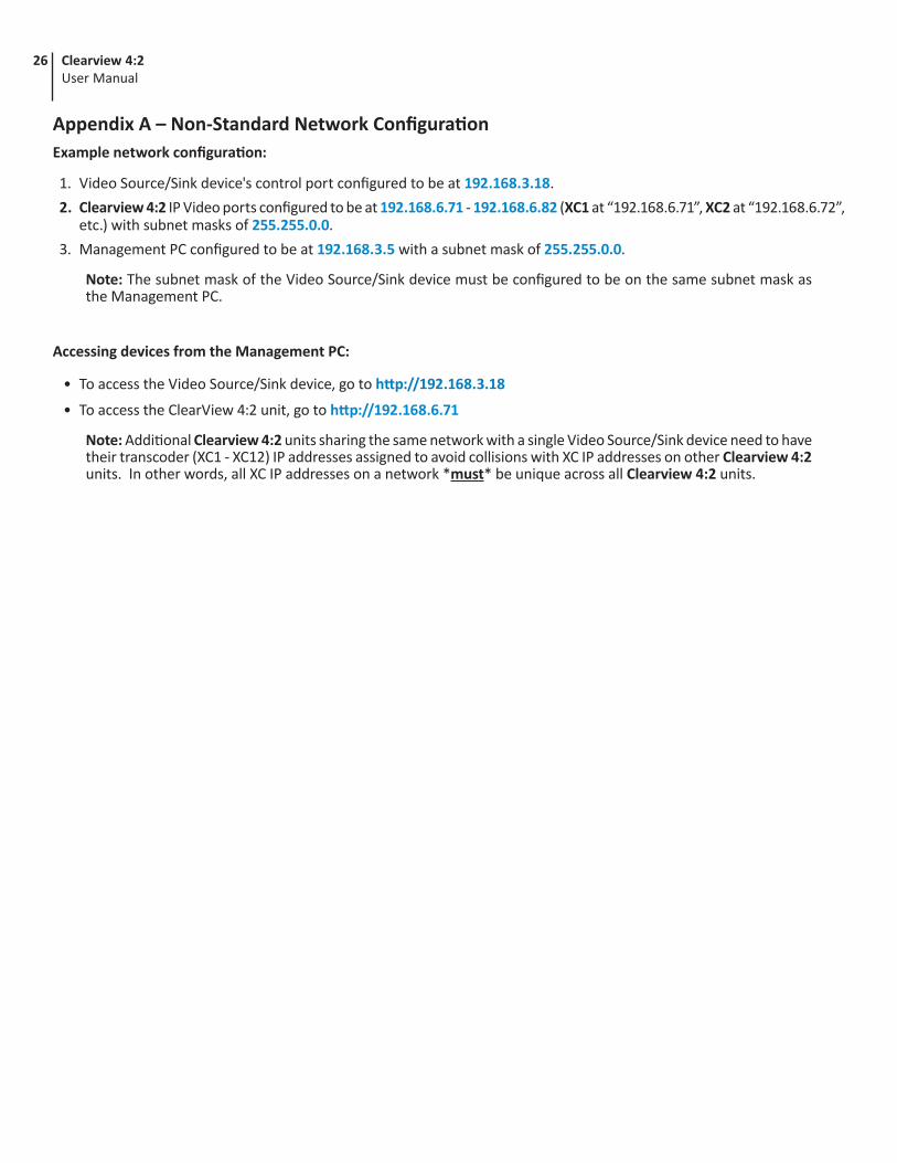
Appendix A – Non-Standard Network ConfigurationExample network configuration:
1. Video Source/Sink device's control port configured to be at 192.168.3.18.2. Clearview 4:2 IP Video ports configured to be at 192.168.6.71 - 192.168.6.82 (XC1 at “192.168.6.71”, XC2 at “192.168.6.72”,
etc.) with subnet masks of 255.255.0.0.3. Management PC configured to be at 192.168.3.5 with a subnet mask of 255.255.0.0.
Note: The subnet mask of the Video Source/Sink device must be configured to be on the same subnet mask as the Management PC.
Accessing devices from the Management PC:
• To access the Video Source/Sink device, go to http://192.168.3.18
• To access the ClearView 4:2 unit, go to http://192.168.6.71
Note: Additional Clearview 4:2 units sharing the same network with a single Video Source/Sink device need to have their transcoder (XC1 - XC12) IP addresses assigned to avoid collisions with XC IP addresses on other Clearview 4:2 units. In other words, all XC IP addresses on a network *must* be unique across all Clearview 4:2 units.
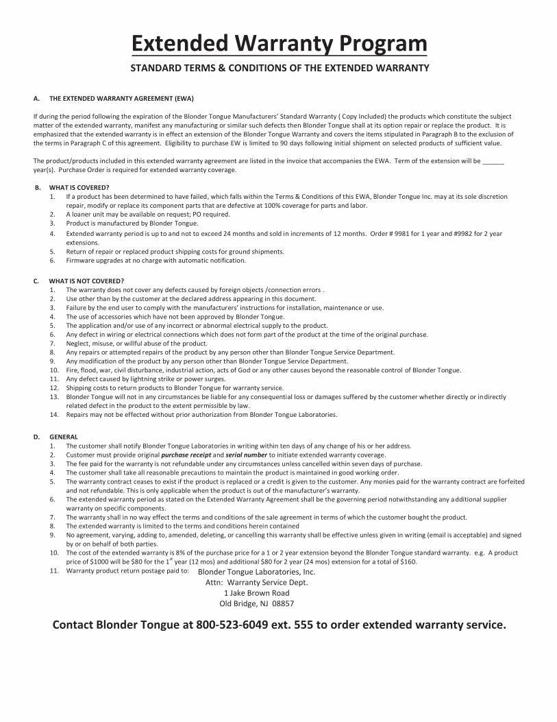
Extended Warranty ProgramSTANDARD TERMS & CONDITIONS OF THE EXTENDED WARRANTY
A. THE EXTENDED WARRANTY AGREEMENT (EWA)
If during the period following the expiration of the Blonder Tongue Manufacturers’ Standard Warranty ( Copy Included) the products which constitute the subject matter of the extended warranty, manifest any manufacturing or similar such defects then Blonder Tongue shall at its option repair or replace the product. It is emphasized that the extended warranty is in effect an extension of the Blonder Tongue Warranty and covers the items stipulated in Paragraph B to the exclusion of the terms in Paragraph C of this agreement. Eligibility to purchase EW is limited to 90 days following initial shipment on selected products of sufficient value.
The product/products included in this extended warranty agreement are listed in the invoice that accompanies the EWA. Term of the extension will be ______ year(s). Purchase Order is required for extended warranty coverage.
B. WHAT IS COVERED?1. If a product has been determined to have failed, which falls within the Terms & Conditions of this EWA, Blonder Tongue Inc. may at its sole discretion
repair, modify or replace its component parts that are defective at 100% coverage for parts and labor.2. A loaner unit may be available on request; PO required.3. Product is manufactured by Blonder Tongue.4. Extended warranty period is up to and not to exceed 24 months and sold in increments of 12 months. Order # 9981 for 1 year and #9982 for 2 year
extensions.5. Return of repair or replaced product shipping costs for ground shipments.6. Firmware upgrades at no charge with automatic notification.
C. WHAT IS NOT COVERED?1. The warranty does not cover any defects caused by foreign objects /connection errors .2. Use other than by the customer at the declared address appearing in this document.3. Failure by the end user to comply with the manufacturers’ instructions for installation, maintenance or use.4. The use of accessories which have not been approved by Blonder Tongue.5. The application and/or use of any incorrect or abnormal electrical supply to the product.6. Any defect in wiring or electrical connections which does not form part of the product at the time of the original purchase.7. Neglect, misuse, or willful abuse of the product.8. Any repairs or attempted repairs of the product by any person other than Blonder Tongue Service Department.9. Any modification of the product by any person other than Blonder Tongue Service Department.10. Fire, flood, war, civil disturbance, industrial action, acts of God or any other causes beyond the reasonable control of Blonder Tongue.11. Any defect caused by lightning strike or power surges.12. Shipping costs to return products to Blonder Tongue for warranty service.13. Blonder Tongue will not in any circumstances be liable for any consequential loss or damages suffered by the customer whether directly or indirectly
related defect in the product to the extent permissible by law.14. Repairs may not be effected without prior authorization from Blonder Tongue Laboratories.
D. GENERAL1. The customer shall notify Blonder Tongue Laboratories in writing within ten days of any change of his or her address.2. Customer must provide original purchase receipt and serial number to initiate extended warranty coverage.3. The fee paid for the warranty is not refundable under any circumstances unless cancelled within seven days of purchase.4. The customer shall take all reasonable precautions to maintain the product is maintained in good working order.5. The warranty contract ceases to exist if the product is replaced or a credit is given to the customer. Any monies paid for the warranty contract are forfeited
and not refundable. This is only applicable when the product is out of the manufacturer’s warranty.6. The extended warranty period as stated on the Extended Warranty Agreement shall be the governing period notwithstanding any additional supplier
warranty on specific components.7. The warranty shall in no way effect the terms and conditions of the sale agreement in terms of which the customer bought the product.8. The extended warranty is limited to the terms and conditions herein contained9. No agreement, varying, adding to, amended, deleting, or cancelling this warranty shall be effective unless given in writing (email is acceptable) and signed
by or on behalf of both parties.10. The cost of the extended warranty is 8% of the purchase price for a 1 or 2 year extension beyond the Blonder Tongue standard warranty. e.g. A product
price of $1000 will be $80 for the 1st year (12 mos) and additional $80 for 2 year (24 mos) extension for a total of $160.11. Warranty product return postage paid to: Blonder Tongue Laboratories, Inc.
Attn: Warranty Service Dept. 1 Jake Brown Road
Old Bridge, NJ 08857
Contact Blonder Tongue at 800-523-6049 ext. 555 to order extended warranty service.

Limited WarrantyBlonder Tongue Laboratories, Inc. (BT) will at its sole option, either repair or replace (with a new or factory reconditioned product, as BT may determine) any product manufactured by BT which proves to be defective in materials or workmanship or fails to meet the specifications which are in effect on the date of shipment or such other specifications as may have been expressly agreed upon in writing (i) for a period of one (1) year from the date of original purchase (or such shorter period of time as may be set forth in the license agreement specific to the particular software being licensed), with respect to iCentral™ (hardware and software) and all other software products (including embedded software) licensed from BT, (ii)) for a period of one (1) year from the date of original purchase, with respect to all MegaPort, IPTV products and fiber optics receivers, transmitters, couplers and integrated receivers/distribution amplifiers (including TRAILBLAZER™, RETRO-LINX™ and TWIN STAR™ products) as well as for VideoCipher® & DigiCipher® satellite receivers, and (iii) for a period of three (3) years from the date of original purchase, with respect to all other BT products. Notwithstanding the foregoing, in some cases, the warranty on certain proprietary sub-assembly modules manufactured by third party vendors and contained in BT products and on certain private-label products manufactured by third parties for resale by BT are of shorter duration or otherwise more limited than the standard BT limited warranty. In such cases, BT’s warranty with respect to such third party proprietary sub-assembly modules and private-label products will be limited to the duration and other terms of such third party vendor’s warranty. In addition, certain products, that are not manufactured but are resold by BT, carry the original OEM warranty for that product. The limited warranty set forth in this paragraph does not apply to any product sold by BT, which at the time of sale constituted a Closeout Product.
BT will at its sole option, either repair or replace (with a new or factory reconditioned product, as BT may determine) any product sold by BT which at the time of sale constituted a refurbished or closeout items (“Refurbished Product” and “Closeout Product”), which proves to be defective in materials or workmanship or fails to meet the specifications which are in effect on the date of shipment or such other specifications as may have been expressly agreed upon in writing, for a period of ninety (90) days from the date of original purchase. Notwithstanding the foregoing, in some cases, the warranty on third party software and on certain proprietary sub-assembly modules manufactured by third party vendors and contained in BT products and on certain private-label products manufactured by third parties for resale by BT are of shorter duration or otherwise more limited than the BT limited warranty for Closeout Products. In such cases, BT’s warranty for Closeout Products constituting such third party software, third party proprietary sub-assembly modules and private-label products will be limited to the duration and other terms of such third party vendor’s warranty. In addition, notwithstanding the foregoing, (i) certain Closeout Products that are not manufactured (but are resold) by BT, carry the original OEM warranty for such products, which may be longer or shorter than the BT limited warranty for Refurbished or Closeout Products. All sales of Refurbished or Closeout Products are final.
To obtain service under this warranty, the defective product, together with a copy of the sales receipt or other satisfactory proof of purchase and a brief description of the defect, must be shipped freight prepaid to: Blonder Tongue Laboratories, Inc., One Jake Brown Road, Old Bridge, New Jersey 08857.
This warranty does not cover damage resulting from (i) use or installation other than in strict accordance with manufacturer’s written instructions, (ii) disassembly or repair by someone other than the manufacturer or a manufacturer-authorized repair center, (iii) misuse, misapplication or abuse, (iv) alteration, (v) lack of reasonable care or (vi) wind, ice, snow, rain, lightning, or any other weather conditions or acts of God.
OTHER THAN THE WARRANTIES SET FORTH ABOVE, BT MAKES NO OTHER WARRANTIES OR REPRESENTA-TIONS OF ANY KIND, EXPRESS OR IMPLIED, AS TO THE CONDITION, DESCRIPTION, FITNESS FOR A PARTIC-ULAR PURPOSE, MERCHANTABILITY OR AS TO ANY OTHER MATTER, AND SUCH WARRANTIES SUPERSEDE ANY ORAL OR WRITTEN WARRANTIES OR REPRESENTATIONS MADE OR IMPLIED BY BT OR BY ANY OF BT’S EMPLOYEES OR REPRESENTATIVES, OR IN ANY OF BT’S BROCHURES, MANUALS, CATALOGS, LITERATURE OR OTHER MATERIALS. IN ALL CASES, BUYER’S SOLE AND EXCLUSIVE REMEDY AND BT’S SOLE OBLIGA-TION FOR ANY BREACH OF THE WARRANTIES CONTAINED HEREIN SHALL BE LIMITED TO THE REPAIR OR REPLACEMENT OF THE DEFECTIVE PRODUCT F.O.B. SHIPPING POINT, AS BT IN ITS SOLE DISCRETION SHALL DETERMINE. BT SHALL IN NO EVENT AND UNDER NO CIRCUMSTANCES BE LIABLE OR RESPONSIBLE FOR ANY CONSEQUENTIAL, INDIRECT, INCIDENTAL, PUNITIVE, DIRECT OR SPECIAL DAMAGES BASED UPON BREACH OF WARRANTY, BREACH OF CONTRACT, NEGLIGENCE, STRICT TORT LIABILITY OR OTHERWISE OR ANY OTHER LEGAL THEORY ARISING DIRECTLY OR INDIRECTLY FROM THE SALE, USE, INSTALLATION OR FAILURE OF ANY PRODUCT ACQUIRED BY BUYER FROM BT.
All claims for shortages, defects and non-conforming goods must be made by Buyer in writing within five (5) days of receipt of merchandise, which writing shall state with particularity all material facts, concerning the claim then known to Buyer. Upon any such complaint, Buyer shall hold the goods complained of intact and duly protected, for a period of up to sixty (60) days. Upon the request of BT, Buyer shall ship such allegedly nonconforming or defective goods, freight prepaid to BT for examination by BT’s inspection department and verification of the defect. BT, at its option, will either repair, replace or issue a credit for products determined to be defective. BT’s liability and responsibility for defective products is specifically limited to the defective item or to credit towards the original billing. All such replacements by BT shall be made free of charge f.o.b. the delivery point called for in the original order. Products for which replacement has been made under the provisions of this clause shall become the property of BT. Under no circumstances are products to be returned to BT without BT’s prior written authorization. BT reserves the right to scrap any unauthorized returns on a no-credit basis. Any actions for breach of this contract must be commenced by Buyer within thirteen (13) months after the cause of action has accrued. A copy of BT’s standard terms and conditions of sale, including the limited warranty, is available from BT upon request. Copies of the limited warranties covering third party proprietary sub-assembly modules and private label products manufactured by third parties are also available from BT on request. VideoCipher® & DigiCipher® are registered trademarks of Motorola Corp.
Rev 5/6/2009
Blonder Tongue Laboratories, Inc.
Limited Warranty
Blonder Tongue Laboratories, Inc. (BT) will at its sole option, either repair or replace (with a new or factory reconditioned product, as BT may determine) any product manufactured by BT which proves to be defective in materials or workmanship or fails to meet the specifications which are in effect on the date of shipment or such other specifications as may have been expressly agreed upon in writing (i) for a period of one (1) year from the date of original purchase (or such shorter period of time as may be set forth in the license agreement specific to the particular software beinglicensed), with respect to iCentral™ (hardware and software) and all other software products (including embedded software) licensed from BT, (ii) )for a period of one (1) year from the date of original purchase, with respect to all MegaPort™, IPTV products, and fiber optics receivers, transmitters,couplers and integrated receiver/distribution amplifiers (including TRAILBLAZER™, RETRO-LINX™ and TWIN STAR™ products) as well as for DigiCipher ® satellite receivers, and (iii) for a period of three (3) years from the date of original purchase, with respect to all other BT products. Notwithstanding the foregoing, in some cases, the warranty on certain proprietary sub-assembly modules manufactured by third-party vendors and contained in BT products and on certain private–label products manufactured by third-parties for resale by BT are of shorter duration or otherwise more limited than the standard BT limited warranty. In such cases, BT's warranty with respect to such third-party proprietary sub-assembly modules and private-label products will be limited to the duration and other terms of such third-party vendor's warranty. In addition, certain products, that are not manufactured but are resold by BT, carry the original OEM warranty for such products. The limited warranty set forth in this paragraph does not apply to any product sold by BT, which at the time of sale constituted a Refurbished/Closeout Product.
(b) BT will at its sole option, either repair or replace (with a new or factory-reconditioned product, as BT may determine) any product sold by BTwhich at the time of sale constituted a refurbished or closeout item (“Refurbished/Closeout Product”), which proves to be defective in materials orworkmanship or fails to meet the specifications which are in effect on the date of shipment or such other specifications as may have been expresslyagreed upon in writing, for a period of ninety (90) days from the date of original purchase. Notwithstanding the foregoing, in some cases thewarranty on third party software and on certain proprietary sub-assembly modules manufactured by third-party vendors and contained in BT products and on certain private–label products manufactured by third-parties for resale by BT are of shorter duration or otherwise more limited than the BTlimited warranty for Refurbished/Closeout Products. In such cases, BT's warranty for Refurbished/Closeout Products constituting such third party software, third-party proprietary sub-assembly modules and private-label products will be limited to the duration and other terms of such third-party vendor's warranty. In addition, notwithstanding the foregoing, (i) certain Refurbished/Closeout Products that are not manufactured (but are resold)by BT, carry the original OEM warranty for such products, which may be longer or shorter than the BT limited warranty for Refurbished/Closeout Products. All sales of Refurbished/Closeout Products are final.
To obtain service under this warranty, the defective product, together with a copy of the sales receipt or other satisfactory proof of purchase and a brief description of the defect, must be shipped freight prepaid to: Blonder Tongue Laboratories, Inc., One Jake Brown Road, Old Bridge, New Jersey 08857.
This warranty does not cover damage resulting from (i) use or installation other than in strict accordance with manufacturer's written instructions, (ii)disassembly or repair by someone other than the manufacturer or a manufacturer-authorized repair center, (iii) misuse, misapplication or abuse, (iv) alteration, (v) lack of reasonable care or (vi) wind, ice, snow, rain, lightning, or any other weather conditions or acts of God.
OTHER THAN THE WARRANTIES SET FORTH ABOVE, BT MAKES NO OTHER WARRANTIES OR REPRESENTATIONS OFANY KIND, EXPRESS OR IMPLIED, AS TO THE CONDITION, DESCRIPTION, FITNESS FOR A PARTICULAR PURPOSE, MERCHANTABILITY, OR AS TO ANY OTHER MATTER, AND SUCH WARRANTIES SUPERSEDE ANY ORAL OR WRITTENWARRANTIES OR REPRESENTATIONS MADE OR IMPLIED BY BT OR BY ANY OF BT’S EMPLOYEES ORREPRESENTATIVES, OR IN ANY OF BT’S BROCHURES MANUALS, CATALOGS, LITERATURE OR OTHER MATERIALS. IN ALL CASES, BUYER’S SOLE AND EXCLUSIVE REMEDY AND BT’S SOLE OBLIGATION FOR ANY BREACH OF THEWARRANTIES CONTAINED HEREIN SHALL BE LIMITED TO THE REPAIR OR REPLACEMENT OF THE DEFECTIVEPRODUCT F.O.B. SHIPPING POINT, AS BT IN ITS SOLE DISCRETION SHALL DETERMINE. BT SHALL IN NO EVENT ANDUNDER NO CIRCUMSTANCES BE LIABLE OR RESPONSIBLE FOR ANY CONSEQUENTIAL, INDIRECT, INCIDENTAL,PUNITIVE, DIRECT OR SPECIAL DAMAGES BASED UPON BREACH OF WARRANTY, BREACH OF CONTRACT, NEGLIGENCE,STRICT TORT LIABILITY OR OTHERWISE OR ANY OTHER LEGAL THEORY, ARISING DIRECTLY OR INDIRECTLY FROM THE SALE, USE, INSTALLATION OR FAILURE OF ANY PRODUCT ACQUIRED BY BUYER FROM BT.
All claims for shortages, defects, and non-conforming goods must be made by the customer in writing within five (5) days of receipt of merchandise,which writing shall state with particularity all material facts concerning the claim then known to the customer. Upon any such claim, the customershall hold the goods complained of intact and duly protected, for a period of up to sixty (60) days. Upon the request of BT, the customer shall ship such allegedly non-conforming or defective goods, freight prepaid to BT for examination by BT's inspection department and verification of the defect. BT, at its option, will either repair, replace or issue a credit for products determined to be defective. BT's liability and responsibility for defective products is specifically limited to the defective item or to credit towards the original billing. All such replacements by BT shall be madefree of charge f.o.b. the delivery point called for in the original order. Products for which replacement has been made under the provisions of this clause shall become the property of BT. Under no circumstances are products to be returned to BT without BT's prior written authorization. BT reserves the right to scrap any unauthorized returns on a no-credit basis. Any actions for breach of a contract of sale between BT and a customer mustbe commenced by the customer within thirteen (13) months after the cause of action has accrued. A copy of BT's standard terms and conditions ofsale, including the limited warranty, is available from BT upon request. Copies of the limited warranties covering third-party proprietary sub-assembly modules and private-label products manufactured by third-parties are also available from BT on request. DigiCipher ® is a registeredtrademark of Motorola Corp. (Rev 0509)
Seller will at its sole option, either repair or replace (with a new or factory reconditioned product, as Seller may determine) any product manufactured or sold (or in the case of software, licensed) by Seller which is defective in materials or workmanship or fails to meet the applicable specifications that are in effect on the date of shipment or such other specifications as may have been expressly agreed upon in writing: (i) for a period of one (1) year from the date of original purchase for all stock hardware products (other than those specifically referenced herein below having a shorter warranty period); (ii) for a period of one (1) year from the date of original purchase, with respect to all MegaPort™, IPTV products, test equipment and fiber optics receivers, transmitters, couplers and integrated receiver/distribution amplifiers; (iii) for a period of one (1) year from the date of original purchase (or such shorter period of time as may be set forth in the license agreement specific to the particular software being licensed from Seller) with respect to all software products licensed from Seller (other than Core Product Software) that is (a) developed for a specific function or application, (b) complimentary to and does not function without the Core Product Software, and (c) listed with a specific model number and stock number in Seller’s Price List (“Non-Core Software”); (iv) for a period of ninety (90) days from the date of original purchase, with respect to non-serialized products and accessories, such as parts, sub-assemblies, splitters and all other products sold by Seller (other than Core Product Software and Refurbished/Closeout Products) not otherwise referred to in clauses (i) through (iii) above. The warranty period for computer programs in machine-readable form included in a hardware product, which are essential for the functionality thereof as specifically stated in the published product specifications (“Core Product Software”) will be coincident with the warranty period of the applicable hardware product within which such Core Product Software is installed.
Software patches, bug fixes, updates or workarounds do not extend the original warranty period of any Core Product Software or Non-Core Software.
Notwithstanding anything herein to the contrary,
(i) Seller’s sole obligation for software that when properly installed and used does not substantially conform to the published specifications in effect when thesoftware is first shipped by Seller, is to use commercially reasonable efforts to correct any reproducible material non-conformity (as determined by Seller in its sole discretion) by providing the customer with: (a) telephone or e-mail access to report non-conformance so that Seller can verify reproducibility, (b) a software patch or bug fix, if available or a workaround to bypass the issue if available, and (c) where applicable, replacement or damaged or defective external media, such as CD-ROM disk, on which the software was originally delivered;
(ii) Seller does not warrant that the use of any software will be uninterrupted, error-free, free of security vulnerabilities or that the software will meet the customer’sparticular requirements; and the customer’s sole and exclusive remedy for breach of this warranty is, at Seller’s option, to receive (a) suitably modified software, or part thereof, or (b) comparable replacement software or part thereof;
(iii) Seller retains all right, title and interest in and to and ownership of all software (including all Core Product Software and Non-Core Software) including any and allenhancements, modifications and updates to the same; and
(iv) in some cases, the warranty on certain proprietary sub-assembly modules manufactured by third-party vendors and contained in Seller’s products, third partysoftware installed in certain of Seller’s products, and on certain private–label products manufactured by third-parties for resale by Seller, will be of shorter duration or otherwise more limited than the standard Seller limited warranty. In such cases, Seller's warranty with respect to such third-party proprietary sub-assembly modules, third-party software and private-label products will be limited to the duration and other terms of such third-party vendor's warranty, if any. In addition, certain products, that are not manufactured by Seller, but are resold by Seller, may carry the original OEM warranty for such products, if any. The limited warranty set forth above does not apply to any product sold by Seller, which at the time of sale constituted a Refurbished/Closeout Product, the limited warranty for which is provided in the following paragraph.
Seller will at its sole option, either repair or replace (with a new or factory-reconditioned product, as Seller may determine) any product sold by Seller which at the time of sale constituted a refurbished or closeout item (“Refurbished/Closeout Product”), which is defective in materials or workmanship or fails to meet the applicable specifications that are in effect on the date of shipment of that product or fails to meet such other specifications as may have been expressly agreed upon in writing between the parties, for a period of ninety (90) days from the date of original purchase. Notwithstanding the foregoing, in some cases the warranty oncertain proprietary sub-assembly modules manufactured by third-party vendors and contained in Seller products, third party software installed in certain of Seller’s products, and on certain private–label products manufactured by third-parties for resale by Seller will be of shorter duration or otherwise more limited than Seller limited warranty for Refurbished/Closeout Products. In such cases, Seller's warranty for Refurbished/Closeout Products constituting such third party proprietary sub-assembly modules, third party software, and private-label products will be limited to the duration and other terms of such third-party vendor's warranty, if any.In addition, notwithstanding the foregoing, (i) certain Refurbished/Closeout Products that are not manufactured (but are resold) by Seller, may carry the original OEM warranty for such products, if any, which may be longer or shorter than Seller’s limited warranty for Refurbished/Closeout Products. All sales of Refurbished/Closeout Products are final.
To obtain service under this warranty, the defective product, together with a copy of the sales receipt, serial number if applicable, or other satisfactory proof of purchase and a brief description of the defect, must be shipped freight prepaid to Seller at the following address: One Jake Brown Road, Old Bridge, New Jersey 08857.
This warranty does not cover failure of performance or damage resulting from (i) use or installation other than in strict accordance with manufacturer's written instructions, (ii) disassembly or repair by someone other than the manufacturer or a manufacturer-authorized repair center, (iii) misuse, misapplication or abuse, (iv) alteration, (v) exposure to unusual physical or electrical stress, abuse or accident or forces or exposure beyond normal use within specified operational or environmental parameters set forth in applicable product specifications, (vi) lack of reasonable care or (vii) wind, ice, snow, rain, lightning, or any other weather conditions or acts of God.
OTHER THAN THE WARRANTIES SET FORTH ABOVE, SELLER MAKES NO OTHER WARRANTIES OR REPRESENTATIONS OF ANY KIND, EXPRESS OR IMPLIED, AS TO THE CONDITION, DESCRIPTION, FITNESS FOR A PARTICULAR PURPOSE, MERCHANTABILITY, OR AS TO ANY OTHER MATTER, AND SUCH WARRANTIES SET FORTH ABOVE SUPERSEDE ANY ORAL OR WRITTEN WARRANTIES OR REPRESENTATIONS MADE OR IMPLIED BY SELLER OR BY ANY OF SELLER’SEMPLOYEES OR REPRESENTATIVES, OR IN ANY OF SELLER’S BROCHURES MANUALS, CATALOGS, LITERATURE OR OTHER MATERIALS. IN ALL CASES, BUYER’S SOLE AND EXCLUSIVE REMEDY AND SELLER’S SOLE OBLIGATION FOR ANY BREACH OF THE WARRANTIES CONTAINED HEREIN SHALL BE LIMITED TO THE REPAIR OR REPLACEMENT OF THE DEFECTIVE PRODUCT F.O.B. SHIPPING POINT, AS SELLER IN ITS SOLE DISCRETION SHALL DETERMINE. SELLER SHALL IN NO EVENT AND UNDER NO CIRCUMSTANCES BE LIABLE OR RESPONSIBLE FOR ANY CONSEQUENTIAL, INDIRECT, INCIDENTAL, PUNITIVE, DIRECT OR SPECIAL DAMAGES BASED UPON BREACH OF WARRANTY, BREACH OF CONTRACT, NEGLIGENCE, STRICT TORT LIABILITY OR OTHERWISE OR ANY OTHER LEGAL THEORY, ARISING DIRECTLY OR INDIRECTLY FROM THE SALE, USE, INSTALLATION OR FAILURE OF ANY PRODUCT ACQUIRED BY BUYER FROM SELLER.
All claims for shortages, defects, and non-conforming goods must be made by the customer in writing within five (5) days of receipt of merchandise, which writing shall state with particularity all material facts concerning the claim then known to the customer. Upon any such claim, the customer shall hold the goods complained of intact and duly protected, for a period of up to sixty (60) days. Upon the request of Seller, the customer shall ship such allegedly non-conforming or defective goods, freight prepaid to Seller for examination by Seller's inspection department and verification of the defect. Seller, at its option, will either repair, replace or issue a credit for products determined to be defective. Seller's liability and responsibility for defective products is specifically limited to the defective item or to credit towards the original billing. All such replacements by Seller shall be made free of charge f.o.b. the delivery point called for in the original order. Products for which replacement has been made under the provisions of this clause shall become the property of Seller. Under no circumstances are products to be returned to Seller without Seller's prior written authorization. Seller reserves the right to scrap any unauthorized returns on a no-credit basis. Any actions for breach of a contract of sale between Seller and a customer must be commenced by the customer within thirteen (13) months after the cause of action has accrued. A copy of Seller's standard terms and conditions of sale, including the limited warranty, is available from Seller upon request. Copies of the l imited warranties covering third-party proprietary sub-assembly modules and private-label products manufactured by third-parties may also be available from Seller on request. (Rev 1021)
One Jake Brown RoadOld Bridge, NJ 08857-1000 USA
732-679-4000 • Fax 732-679-4353www.blondertongue.com