clearinghouse for feueral scientific and technical informatioin … · clearinghouse for feueral...
TRANSCRIPT

CLEARINGHOUSE FOR FEUERAL SCIENTIFIC AND TECHNICAL INFORMATIOIN CFSTIDOCUMENT MANAGEMENT BRANCH 410.11
LIMITATIONS IN REPRODUCTION QUALITY
ACCESSION 0I
Q i. WE REGRET THAT LEGIBILITY OF THIS DOCUMENT IS IN PARTUNSATISFACTORY. REPRODUCTION HAS BEEN MADE FROM BESTAVAILABLE COPY.
"2, A PORTION OF THE ORIGINAL DOCUMENT CONTAINS FINE DETAIL
WHICH MAY MAKE READiNG OF PHVTOCVPY DIFFICULT.
O 3. THE ORIGINAL DOUCUMENT CONTAINS COLOR, BUT DISTRIBUTIONCOPIES ARE AVALABLE IN BLICIN-AtP1D-WHITE REPRODUCTIONONLY.
Q 4. THE INiTIAL DISTRIBUTION POPIES CONTAIN Z'OLCH WHICH WILLBE SHOWN IN BLAC[K.-AND-VIHITE WHEN IT IS h0E•SARY TOREPRINT.
5 5. LIMITED SUPPLY ON HAND: WHEN EXHAUSTED, OCIUMENT WILLBE AVAILABLE IN MICROFICHE ONLY.
6 6. LIMITED SUPPLY ON HAND: WHEN EXHAUSTED DOCUMENT WILLNOT BE AVAILABLE.
Q ". DOCUMENT IS AVAILABLE IN MICF'OFiCHE ONLY.
0 8 . DOCUMENT AVAILABLE ON LOAN FROM CFSTI ( TT DOCUMENTS ONLY),
NBS 9/64 PROCESSOR:

WtbbTECHNICAL LIBRARY
L'opy No. /4" AMP , 42. 2R
Document No. AMG-NYU No. 133
Copy No. 4
THE FORCE OF IMPACT ON A SPHERESTRIKING A WATER SURFACE
N.• SECOND APPROXIMATION"" i • ~ ~COPY ....ZZI•:0F ___L.-_-
K. "-•- •,•HARD COPY $. ?_.c•
MICROFICHE $. .9,vWITH THE APFPOVAL OF TP4E OFFlCF OF THE SCHAIRMAN
OF ItHE rA 1 .C '. ' r[SEARCH
"COMMITTLE. THIS "LP. -I -A .SI IED
(- Bý THE OFFICE (F S ,A i , L ... Al AND
DEVELOPMENT.
Prepared for the
APPLIED MATHEMATICS PANEL
NATIONAL DEFENSE RESEARCH COMMITTEE
By the
Applied Mathematics Group
New York University
Thns document c-ftains informationaF-ct'rg the Nat;omol Defense of the
Ur%.*od States w;tI,;n the r-..on;mg of the 1 4Esonaoe Act. U. S. C. .,; and 32. JulyIti-transm~iio, or the -e.Iat~on of 4%Juy I 4co-tents in any manner to an unauthorized
pr•scn ii prohib~ted by law.
DOWNGRADED AT 3 YEAR INTERVALS,DECLASSIFIED AFTER 12 YEARS.
DOI) DIR 5200.10 V

INC) Prepared under Approved for distribution
)C)tract OE~sr-945 Warren WeaverL : Chief, Applied Mathematics Panel
Distribution ListAMP Report 42.2R
Cozy NO*.
1 - 8 Office of the Executive Secretary, OSRD
9 - 51 Liaison Officeq 0SRD
52 - 53 Ordnance Research Center, Aberdeen Proving Ground1 Att: T. L. Smith
54 - 56 Commanding General, Army Air ForcesAtt: T. von Karman
57 - 60 Chief, Bureau of Ordnance1i R. S. Burington1 Comdr. S. Brunauor1 Lt. Comdr. W. E, Bleick
61 - 62 Office of the Chief of Ordnancen 1 H' Me Morse
1 Capt. D. D. Johnston
63 6 65 Director, David Taylor Model Basin1 W. H. Bowers1 E. H. Kennard
66 - 67 Director, Naval Ordnance LaboratoryI Capt. R. D. Bennett1 Ens. D. Gilbarg
68 Director, Naval Research LaboratoryAtts G. R. Irwin
69 Naval Torpedo Station, NewportAtt*. Lt. Comdr. H. C. Pavian
70 - 71 E. B. Wilson, Chief, Division 21 Woods Role Oceanographic Institute
72 - 73 F. L. Hovde, Chief, Division 31 L. Slichter1 S. Bowen
74 - 82 Jo Te Tate, Chief, Division 61 C. Herring1 M. Gim-rich \gTERVALS1 F. C. Lindvall2 Re To K1napp Vo"RAE AFTE 7 2 Y EARS-
DCCLASSr E AE
I L. G. Straub OOO DIR 5200.102. W. V. Houston

Copy No,
83 Commanding General, AAF Materiel Command, Wright FieldAtt: Capt. Jo F. Healy
84 Commanding General,AAF Proving Ground CommandElgin FieldAtt: Col. R. T. Hiff
85 W. Weaver, Chief, Applied Mathematics Panel
86 To C. Fry, Acting Chief, Applied Mathematics Panel
87 L. M. Graves
88 0. Veblon
89 - 92 R. Courant1 Y. ShiffmanI D. C. Spencer
93 S.3. Wilks
94 I. S. Sokolnikoff
95 Me Rees
96 - 98 Garrett Birkhoff1 Norman Levinson1 Lynn Loomis
99 J. G. Kirkwocd
100 F. D. Murnaghan
101 Committee on Medical ResearchAtt: E. Newton Harvey

Table of Contents
PagePreface
i1. Introduction and Summary 22. Photographs of Entry 83. Virtual Mass 94. Hydrodynamic Formulation of the Problem 125,. First Approximation for a Sphere 156. The Wetting Correction 207. The Free Surface Correction 28
8. The Second Approximiation 31
9. Comparison with Experiment 33
Appendix10, Comparison of Energy and Momentum 38
Bibl lography 44
Graphs I - 12 47Plates I - 7 71
PREFACE
In a previous report (AMP Report 42.1)), the problemof vertical impact of a body with a spherical nose on awater-surface was solved mathematically by Max ShIffman andDonald C. Spencer of the New York University Group of theApplied Mathematics Panel. The solution was based on theassumption that the surface of the water is not appreciablyaltered by the entry of the body, an assumption which canbe accepted only as a first appr'oximation.
Therefore, a further study was undertaken, takinginto account the disturbance of the surface of the water.The present report presents the results of these studies.It is shown that the disturbance of the surface leads to twot pea of corrections of the previous results. In the first
ace, the upward rise of the surface of the water wets alarger portion of the entering body, thereby increasing theresistance of the water to the entering body. Secondly, therising surface relaxes somewhat the :restraint imposed on thebody, causing a decrease in the impact force. These twocorrections, which partly cc.2nterbalance one another, areanalyzed here by using a combination of theo,'y and informationderived from experiment. The final result, which deviatessomewhat from the first approximation, is compared withexperiment and shown to be in satisfactory agreement with it.
With the experience gained and the theory developed forvertical entry, it is hoped that the impact forces duringoblique entry will be amenable to treatment. This questionis now being considered by the same authors.
Attention should be drawn to the work of the HarvardGroup of the Applied Mathematics Panel concerning air-waterentry as a whole, and to the activities of the UnderwaterBallistics Conmittee.
The writers were greatly helped by other members of theNew York University Group, in particular by Mr. M. H. Shamos,who made an important contribution by excellent flash photo-graphs he took of spheres entering water. T-ese photographsfurnished much qualitative and numerical information. Thanksare also due to Dr. Patrick Harley of the Morris Dam Group ofthe California Institute of Technology for permission to usethe photographs exhibited in Plate 5; to Dr. R. M. Davies ofthe Engineering Laboratory, Cambridge, Englani for Plate 6;and to Dr. E. Newton Harvey of Princeton University for Plate 7.
R. Cournnt
Director, Contrnct OEMsr-945
_ 2
TEE FORCE OF IMPACT ON A SPHERE STRIKING A WATER SURP•CE
ScSecond Appoxima tion
Se oh lo Introduction and Summar
The entry of a solid body fro n air into water maytake place in two ways: (i) if the speed is small and ifthe surface of the body is smooth, the entry occurs with-out the formation of a cavity (smooth entry); (ii) if th3speed is great or if the surface of the body is rough orhas an irregular shape, the flow detaches from the bodywhen it has penetrated a short distance below the initialsurface level (rough entry). In either case there is aninitial period following contact with the surface duringwhich the body experiences the greatest deceleration andwhich is of such short duration that cavitation has notyet developed. The determination of the forces actingduring this i act stage of the entry ib important in thecase of pro otiles shot or dropped into water, not onlybecause possible damage to the mechan~ism and nose butalso cause the impulsive forces and torques created-bythe mpact influence the underwater trajectory of the pro-
ctileo
# W-oupoeej that the nose of the projectile is spheri-cal in shape and.that the initial impact with the surface isvertical. 4 ithen the mass 'of the projectilewas concentrated into a sphere o the same radius as the nose.In a prev'ious reporr"t E A- obtained:a first approximation-,to the force of Impact on a sphere entering vertically bydisregarding the rise of the surface; in the present report
eb a second approximation,by estimating the effectsSof the surface motion aqtheoretical estimates
W- ,,wit h experimentlJ- &kL4
* Numbers in bra ts [ ] ref4 o the bibliograph7 at the endof this report.

The resultant upward force P acting on the sphere
in the impact stage can be expressed in terms of a dimen-
sionless impact-drag coefficient C P. Let A be the radius
of the sphere, U0 ite initial velocity upon impact, and
/ the density of water. Then the impact force may be
conveniently expressed as
P = _ o'f A2 . Cp
where Cp is the "impact-drag coefficient." The coefficient
Cp depends on the time; it is zero when the sphere first
strikes the surface, rapidly increases to a maximum value,
and then decreases.
The impact-drag coefficient Cp may be expressed in
terms of the "virtual mass" of the fluid. If U is the
velocity of the sphere at time t, we define the virtual
mass of the fluid to be a quantity M such that MU is the
total vertical impulse corxu=nicated to the fluid during
the time interval t; in other words M is defined by the
equationd
P A (MU).
Let B denote the depth of penetration of the bottom of the
sphere below the initial surface level, and let b = B/A.

4
Introducing the additional dimensionless quantity= M/ffo.we obtain Li Seotion 3 the formula /
dm
(i 3m 3
where c' is thle uspecific gravity" of the incoming projectile
considered as thoug&_, the whol' mass were concentrated into
a sphere having the sane radius as the nose,
mass of projectile
14 3
Our final estimate of C as a function of b is plotted
in Graph 1 for various valuos of T. (All graphs are collected
together at the end of the report. For the sake of convenience,
Graph 1 is also inserted on the next page.) For values of 6
ranging from.. I to 0o, the impact drag coefficient Cp rises very
rapidly to a peak of about 1, the peak occurring when the sphere
has penetrated to a distance of from 0.1 to 0.2 of a radius
below the initial surface level. The coefficient Cp then de-
clines more slowly, until at about 0.7 of a radius of entry
its value is equal to the stationary cavity drag value of 0.3
(for description of cavity drag, see (23 and [213).
For sm.ller values of T , this general behavior of Cp
is retained but is shifted downward and to the left.
The question arises whether, in rough entry, the cavity
farmation which takes place will interfere with the above re-
sults and partly vit-ate them. It is known from both experimen-
tal and theoretical grounds that the cavity begins to form ,ly
after the sphere, has submerged a distance somewhere betweern a
quarter of a radius and a radius. Thxts the behavior of Cp do-
picted in Graph 1 still aprlies --- the rapid rise of Cp to a

1 71
............ ..;} . I. ... '
... ... ............
'Il
0
..... ....

5
maximum of about 1, and the slower decline to the cavity
drag value of 0.3. The brief impact stage in rough entry
is the same as in smooth entry.
The dimensionless virtual mass m defined by m = M/IYpA3
is plotted as a function of b in Graph 3. For purposes of com-parison we have plotted in the same graph our first approxima-
tion for m, taken from th6 previous report [15]. Likewise,
in Graph 2, our corrected estimate of Cp in the case T - 00
is compared with our first approximation obtained in (15). In
the corrected estimate, the maximum of Cp is somewhat larger
and is displaced to the left.
The first approximation of the impact-drag coefficient
was derived in our report [15) under the assumption that the
surface does not rise, the surface remaining plane and at its
initial level. Under these circumstances the flow at each
instant t depends only on the depth of penetration below the
initial level and on the velocity of the sphere at that instantt and is otherwise independent of the past history of the entry;
for this reason the flow might be called "quasi-steady."
In the present report a second approximation i obtained
which takes into account the past history of the phenomenon.
The corrections are of two sorts. On the one hand the waterrises and wets a larger portion of the spberical surface than
it would if the surface did not rise. The fluid therefore
exerts pressure over a larger area and increases the total
impact force. This will be called the "wetting correction.*
On the other hand, the free surface rises and relaxes to a
certain extent the restraint imposed on the sphere. This willbe called the "surface correction." These two corrections
are discussed in Sections 6 and 7 respectively, and both are
combined in Section 8 to give the final estimate of the impact-
drag coefficient CPOIn Section 9 this final estimate of C is compared with
experinIntal measurements of the impact force on a sphere.

Compar.ison is made with measurements taken by S. Watanabe's
[17] in 1930, who used a piezoelectric gauge to determine
the force; with rough experiments of Re We Blundell [3] madein 1937; and with recent measurements of g. Go Richardson [13]
Watanabe's experiments were very carefully performed
with aecurate instruments and verified the fact that the impact
force varies as the square of the initial velocity. The value
of the specific gravity c of the sphere in Watanabe's experi-
zent was as low as 0.116. The theoretical Cp curve correspond-
Ing to this value of a- is compared with Watanabe's experimental
curve in Graph 10. Note that the range of b is small, from 0
to .03. The agreement is remarkably good for very small values
of b, when C is increasing rapidly. In fact, near b = 0 the
theory gives
C 6o62bl/'2 - a b 4 ...
where the constant a 2 is not accurately determined by the theory.
The first term 6.62bi/ 2 of this expansion is verified completely
by Watanabe's data. The deviation in the remaining portion of
the curve is due to the second coefficient a 2 .
In Blundell's experiment, a* ranged from .2 and .3 approxi-
mately. The experimental curves, transcribed to the dimension-
less form of a drag coefficient, are shown in Graph 11(a), and
the corresponding theoretical curves are drawn in Graph 11(b).
An idea of the rather large experimental error may be seen by
comparing curves (B) and (C) which should be identical, and from
the fact that curve (D) should be the highest (since r- is the
largest). The experiments at least give an idea of the order of
magnitude of the impacttfrces and of their' duration, and the
agreement with theory is satisfactory. In fact, curve (D) even
agrees nu mrically with theory.
In Richardson's experiment, T = .16. The corresponding
theoretical curve is compared with Richardson's in Graph 12,

and the agreeeznt is fair. Again, Richardson's experiment
should be considered as yielding only the order of magnitude
of Cp
In each of these experiments, the value of r- is small.
It would be desirable to carry out experiments with larger
values of 6', using accurate instruments (such as piezoelectric
gauges).
In addition to the impact force, it is of interest to
know the average pressure p acting over the portion of the
sphere in contact with the water. This pressure can be writtern
in the form
p fU 270* p
where D is a dimensionless coefficient. The dependence ofp
Son b = B/A is shown in Graph 4 (for the case T = oc). Itis noteworthy that the value of • at the initial a:ntact ofthe sphere with the water is infinite. Actually, because ofthe compressibility of the water and bocause of the fact that
the compression wave is initially a plane wave, the pressure
during this phase is approximately cUo where c is the speed
of sound in water. This would give a value of Dp approximately2c 2o
equal to 0o" The intersection of the straight line =
with Graph 4 gives an indication of the time interval in which
compressibility plays a role.* * Mhs, the effect of compress bility
* Using the asymptotic formulaD=2.2
61/2
for small b, and equating this to 2c ' one obtains
as an estimate of the relative depth of penetration in whichcompressibility plays a role. Even if the initial entryvelocity Uo is as high as 500 ft/sec this yields b = .01, anorder of magnitude which is negligible.
This idea was also suggested by M. Gimprich.

- 8
is to reduce the value of D and therefore of Cp at the
very beginning.
Concerning the actual distribution of pressure overthe wetted portion of the sphere. we remark that the pressure
is not greatest at the lowest point of the sphere (stagnationpoint). This fact arises from the non-stationary character
of the flow, and the usual conceptions based on stationary
flow do not apply. On the contrary, the pressure is a mini-
mum at the lowest point of the sphere and has a very sharpand high maximum near the edge of the wetted portion of thesphere. This fact was derived theoretically by Wagner [161]
in the two-dimensional case of the entry of a very flat wedge.
However, an estimate of the depth at which stationary flowapproximately sets in can be obtained by determining when Cp
is about 0.3. This occurs for b = .7 approximately.
Seotion 2. Photographs of Entry
The interesting sequence of events produced by entryof a sphere from air into water was first photographed anddescribed by Worthington [19]. Plate 1 is a reproduction
of some of his photographs and shows several stages in the
smooth entry of a sphere. A more complete sequence, whichshows the splash in greater detail, is given in Plates 2,3.
As m.y be observed from these two sets of pictures the phenom-ena accompanying smooth entry are closely duplicated in differ-ent experiments. Even the jets produced as the water envelopes
the spheres differ little in appearance.
In order to show more clearly the splash during impact,
an enlarged photograph is reproduced in Plate 4. We observethat the splash is largely concentrated in the immediate
neighborhood of the sphere and is composed of a relatively
thick base from which a thin sheath rises up along the sidesof the sphere. A few drops which have detached themselves maybe seen at the top of the sheath.

Because of the speed with which projectiles are
usually launched into water their entry is rough. In fact,
the entry of a bomb, mine, or torpedo takes place in three
stages: (I) the initial impact stage which begins when the
projectile touches the surface and ends when cavitation
developes; (ii) motion through the water with a trailing
cavity extending to the surface; (iii) motion after the
cavity is closed. The closure of the cavity takes place
either at the surface or below the surface, but in either
case the projectile carries with " a pulsating air bubble
which gradually disappears.
The initial stage of the rough entry of a sphere is
shown in Plate 5. The sheath, which persists alongside the
sphere in the case of smooth entry, detaches in rough entry
and may break up into spray. However, the thick base of the
splash remains in contact with the sphere and is the same as
in smooth entry. So far as estimation of impact force is
concerned, the effect of the sheath is negligible compared to
that of the thick base.
The further stages of rough entry are shown in Plate 6.
Unfortunately only the first photograph shows the sphere in the
impact phase and here the splash cannot be seen very clearly.
However, the sheath can be seen as a light band surrounding the
sphere above the surface.
For the usual projectile entering water the speed does
not exceed five or ten percent of sound speed in water. It is
therefore reasonable to neglect compressibility effects. For
the sake of general. interest, we include Plate 7, which shows
a sphere entering at roughly half the speed of sound in water.
Here the effect of the compressibility is of course important.
Section 3. Virtual Mass
The impact drag coefficient Cp will be obtained in terms
of the Ovirtual mass" M of the flnLid. Let U be the downward

10
velocity of the spbare at any instant t, and let P be the
resultant upward Impact force exerted on the sphere. Then
the sphere exerts a downward force P on the fluid and im-
parts momentum to the fluid. The "virtual mass" M of the
fluid at a given instant t is defined by
(3.1) Prd+(MU) o
Let M0 be the mass of the incoming projectile. Neg-
lecting gravity compared to the impact force P, we have
(32) p = (MoU
Adding (3.1) and (3.2) we obtain d [(M + Mo) U] = o and so
integrating,
(3.3) (M + Mo)U= MoU0 or U= .1 + MI/Mo
where Uo is the velocity of the incoming sphere at the initial
inatant of contact with the fluid#
Let B = B(t) be the distance at time t of the lowest
point of the sphere from the initial surface level; the velocity
U of the sphere is then B = * * By differentiating (3.3) withdt
*Thus MU is the vertical impulse contributed to the fluid bythe moving sphere. It is also possible to introduce a virtualmass based on the kinetic energy of the fluid, but for the caseof impact it differs from the virtual mass defined above. Thisis to be expected from general considerations of inelastic im-pact. We shall use throughout this report the definition(3.1) of the virtual mass, based on momentum; Justificationof this choice is given in the Appendix.

A
respect to t and using (3.2), it follows that
(3.4) = d / d _. , ,a/1 + (l÷+M ) 0•I *o Mo
Let A denote the radius of the incoming sphere, and let p bethe density of water. Introducing the dimensionless quantities
(35)M b-- p A'
22we may write
(3.6) p U2 ir A 2
wheredm(:;.'.7 ) Cp -
(1 M )Mo

12
For incoming projectiles of large mass compared to
the mass of the water displaced by the hemisoherical nose,
- may be neglected compared to 1. Then the impact dragdm
c 8 efficient Cp is merely av. Also, from (3.3), the change
in velocity U in the impact stage is small.
However, if M 0 is not large compared to M, the denom-
inator in (3.2) must be retained. This is the case in the
experiments which will be cited in Section 9, and it is con-
venient to put the denominator in a slightly different form.
Let a* be the specific gravity of the incoming projectile
considered as though the whole mass were concentrated into a
sphere iI'f the incoming projectile is not already a sphere),i.e,,
(3.8) T 0
4 3
Using (3.5), equation (3.7) may be written
dm
(3.9) C o(l -3 3
The determination of the impact-drag coefficient Cp requires
merely the determination of the dimensionless virtual mass m.
Section 4. Hydrodynamic Formulation of the Problem.
We shall neglect the effects of compressibility and of
the viscosity of the fluid. Since the fluid is at rest before
the sphere strikes it, the flow of the 'fluid at each instant
of time t is irrotational and can be described. by a velocity
potential 14. This is a function V/(x, y, z, t) defined over
the region of space occupied by the fluid such that
- grad K
is the velocity of the fluid at the instant t and the position
13
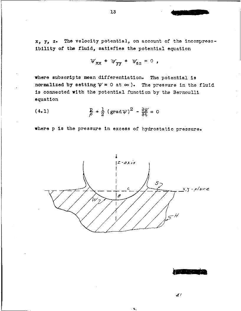
x, y, z. The velocity potential, on account of the inconpress-
ibility of the fluid, satisfies the potential equation
-V/xx + (yy + z z = o0,
where subscripts mean differentiation. The potential is
normalized by setting 141 = 0 at 0o). The pressure in the fluid
is connected with the potential function by the Bernoulli
equation
(4.1) P + (grad )2 t 0
where p is the pressure in excess of hydrostatic pressure.
Z -ax 15
X,~ -;P A/>,e-
!-.//

14
To obtain the impact force exerted on the sphere,
we shall use the principle of conservation of momentum.
The total momentum of the fluid is directed vertically
downward because of the rotational aymmetry and is equal
to
(4.2) ffr dxd~y'dz df~'xdy dnfxd-y
Here V is the wetted portion of the sphere, S is the free
surface, and the last term in (4.2) means the limit of the
integralffVdxdy extended over the submerged portion H of a
large spheri.cal surface the radius of which tends to infinity.
The external forces acting on the fluid contained in
the membrane H are: (i) the downward force of magnitude P
exerted by the sphere and (ii) the upward force exerted on H
by the pressure of the fluid exteial to it. (The resultant
force due to the constant atmospheric. pressure is zero. The
only effect of gravity is the buoyancy which Is negligible
compared to the impact force P.) Th' force (ii) is equal tothe time rate of change of the last ter. in (4.2). For, by
Bernoulli's law (4.1), the force (ii) differs from the timerate of change of the last term by a term of the form
fJ(grad Y) 2 dxdyH
which approaches zero as the radius of R becomes irfinite.
(For, at oo, y behaves at worst like • therefore (grad v)2like 1 and the whole integral like- 1
2 ) . Likewise themomentum flux through the surface H consitits ofi integrals of
squares of velocities, and these approach zero as the radius
of H becomes inifinite. Since the resultant of all the ex-
ternal forces is equal to the time rate of change of the
momentutm (4.2), we therefore have
(4,3) P d ( ,fj- jy)

15
The formula (4.3) can also be inferred directly from
the known physical interpretation of the potential function
y", namely that ,OV is the impulsive pressure required to
produce the flow.It is convenient to exhibit separately the effect of
the velocity B of the sphere by setting
(4.4) YC(x, y, z, t)= ý (x, y, z, t) P
so that * is the instantaneous potential function correspond-
ing to the parameter B and to unity as velocity of the sphere.
Then (4.3) can be written
where
(4.5) M =,ffqdxdy
This formula expresses the virtual mass of the fluid in termsof the potential function 0 .
Section 5. The First Approximation for a Sphere
Consider the flow produced in the fluid as a resultof the entry of the sphere. As the sphere penetrates thesurface, the free surface no longer remains plane but rises
slightly and forms spurts running up the sides of the sphere.
Although the exact shape of the surface is difficult to deter-
mine theoretically, some estimates will be presented in Sec-
tion 6. For the purpose of computing the virtual mass and the
impact force, we shall make a plausible first approximation
in the present section by dioregarding the rise of the surface.More exactly, we shall neglect the rise of the surface and
also the squares of velocities on the surface.

- 16
To determine the potential function y (or •1, it
is necessary to know boundary condition for ,V/ • The exact
boundary condition on the free surfacd S of the fluid is
P= 0
(pressure is atmospheric), which by Bernoulli's equiation
(4.1) can be expressed in terms of the potential function
W by
(5.1)1 (grad )2at 2
Since this exact boundary condition is non-linear and diffi-
cult to apply, we neglect the rise of the surface S andsquares of velocities on S as a first approximation. Thms,
neglecting (gradjr) 2 in (5.1) we have
or, since the free surface S is assumed to remain at its
original level,
(5a2) V = 0 on the initial plane z = 0 (sinceY= 0 at o.
The boundary con,•i4ton (5.2) states that the impulsive
pressure poy is zeto on the surface. This condition would be
correct if the impact took place completely impulsively.
Actually the time interval is very short, and so (5.2) is a
good first approximation.
It is more convenient to use the potential function
Sfor unit velocity, defined by (4.4). The potential
function 0 (depending on B) satisfies the following conditions:

17-
/ AI \
I I
d77' /// /
(a) On the sphere, the negative of the normal- derivative
of & = B is equal to the component of the velocity of
the sphere along the normal, or
" •n -- COS CC
(b) On the initial water level,
=0
There Ls a unique potential function satisfying these con-
ditloný,.
The flow arising from the above boundary conditionshas been constructed explicitly in the preceding report [151.
Because of condition (b), the potential flow can be extended
to the infinite space by reflection on the suz, face and theflow at each instant corresponds to the steady flow about asyinnetrical lens formed by the intersection of two equal

- 18
spheres. A photograph from Worthington (19] is shown below.
This photograph is a view of the entering sphere from slightly
below the surface. The surface reflection creates the upper
side of the lens. (of course, the size and shape of the lens
varies with time.)
The preceding report L15] supplies not only the potential
function $ but also the corresponding virtual mass, which we
sha.ll henceforth denote by ML, the subscript L referrl~ig to a
lens. The results of [15] w~hich we use here may be r urmarized
as follows:(i) The dimension'-ess virtual mas• mL - is a function
rpA5
of b alone (where b = B/A), and will be written as ML(b). Its
dependence on b is drawn in Graph 3. The impact-drag coefficient
cIF depends on b in the manner indicated in Graph 2. The
maxi•umn of dL is .95 and it occurs for b = .24.
When b is small, the spherical segment beneath the initial
level of the fluid is nearly a disc. By a known formula for thevirtual mass M of a disc (see (8], p. 130) we therefore have
M 4 3
for B small, where c is the radius of the circle of inter-
section of the sphere with the original level.
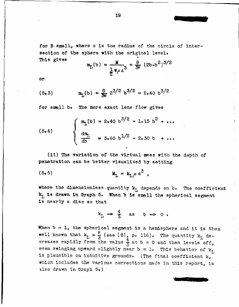
This gives M 8 2b 3/2mL(b) WP 3 = b • -b2)/
or
(5.3) mL(b) 8 23/2 b'3/ 2 = 2.40 b3/ 2
for small b. The more exact lens flow gives
( mL(b) = 2.40 b3/2 - 1.15 b 2 +
(54) dm = 3.60 b/2 2.30 b +...db
(ii) The variation of the virtual mass with the depth of
penetration can be better visualized by setting
(5.5) ML= kL c3 ,
where the dimensionless quantity kL depends on b. The coefficientkL is drawn in Graph 5. When b is small the spherical segmentis nearly a disc so that
4 as b--. 0.
When b = 1, the spherical segment is a hemisphere and it is thenwell known that kL = •- (see [8], p. 116). The quantity kL de--
creases rapidly from the value S at b = 0 and then levels off,even swinging upward slightly near b = 1. This behavior of kLis plausible on intuitive grounds. (The final coefficient k,which includes the various corrections miaJ'd in this report, is
Silso drawn in Graph 5.)

20
It is interesting to note that for the case of a cone
instead of a sphere the quantity k is a constant independent
of the depth of penetration of the cone. This results from
the fact that for a cone the flow patterns at different times
are geometrically similar.
To obtain a second approximation to the virtual mass and
to the impact force, it is necessary to estimate the effects of
the motion of the surface. On intuitive grounds, corrections
due to the motion of the surface can be divided into two parts.
On the one hand the water rises and wets a larger portion of
the sphere, the sphere now exerting pressure on the fluid over
a l/arger area and causing an increase in the total impact force.
This will be called the *wetting" correction. On the other hand,
the free surface of the fluid rises and relaxes somewhat therestraint imposed on the sphere. This will be called the "sur-
face" correction.
These two correotions appear in forimla (4.5) when written
as
(5.6) X = ,Off 0dxdy +Offtdxdy
W 5
The second integral is not zero since the condition (55.1) re-
places * = 0. (In fact, * will turn out to be negative on S.)
Section 6. The Wetting Correction
The greatest disturbance of the surface of the fluid occursalongside the sphere. Here a thin sheath of the fluid rises more
rapidly than the rest, and may detach from the sphere (see Plate 4).
This sheath because of its thinness contributes very little to
the impact force (the pressure of the fluid in the sheath is practi-cally atmospheric). The sphere exerts pressure on the fluid in
the main aver the portion of the sphere obtained by cutting off
the thin s'aeath from the thick *base" of the risen fluid. This
-m-

21
C,
Sf 1 // /
/ /~/,
portion of the sphere is indicated by the points QQ in thediagram, and the separation of thin sheath from the thick
base is indicated by the dotted lines QQ'. The flow of thefluid is due to the portion QQ of the sphere, and is approxi-mately the flow about a lens consisting of the spherical seg-
ment QQ and a horizontal plane free surface QQ'oo . (This
may in fact be taken as the matuematical definition of the
point of demarcation Q between sheath and base.) In otherwords, the "base' below QQI is so thick that its influence on
the sphere is practically the same as if it extended to co .It will be shown later in this section that the above discussion
is exactly verified, and the definition of Q Justified, in theasymptotic case as B -- t 0 *
* For the method used in the practical determination of thispoint of demarcation Q from photographic data, see Plate 4and the accompanying discussion on page :-3.

22
Henceforth it will be the spherical segment QQ which
will be called the "wetted" portion W, or the "effective"
portion, of the sphere. Let B1 be the depth of this effective
portion, and cI the radius of its circular base (see diagram).
The quantity B1 will be called the "effective depth" of penetra-
tion of the sphere. We shall also set
B1
The flow of the fluid is due to the effective portion of the
sphere and is approximately due to a lens with dimensions B1 ,
01 in place of Bc.
The dimensionless virtual mass m = is given by.•7pA3
mL(bl) of the lens flow. Thbs the dimensionless virtual mass
and the drag coefficient dm ared~b
m = mL(bl)
(d. " d-1-M db1 Tb1
dmL(b 1)where mT(bI) and tare determined from the lens flow
db1with the argument bI.
It remains then to determine b1 as a function of b. Set
(6.2) b1 = b . w(b)
(or equivalently, BI = B w(b) ) where w(b) is a function of
b = B/A. The quantity w(b) will be called the "wetting factor."
In this section we shall show theoretically that initially,
for b = 0, the wetting factor w(O) has the value 3/2. The exact
dependence of w(b) on b is extremely difficult to determijne

23
theoretically, but for small values of b the theory shows
that w(b) behaves like 3 - constant .Vf. Consequently,
the variation of w(b) with b was determined from experimental
measurements.
A blackened steel sphere of diameter 2.86 cm was droppedInto a tank of water from a height of 16.2 cm and flash photo-
graphs were taken with the sphere at various stages of immersion.
The photographs in Plates 2 and 3 are a selection showing thesequences of events. Plate 4 shows an enlarged view of the
splash and illustrates how the measurements were made. The
straight line represents the initial surface level, the posi-
tion of which was determined by a pair of inclined needles and
their reflections, as indicated in the photograph. The boundary
of the sphere has been completed by a white line. The exact
line of demarcation between sheath and base is somewhat arbitra-ry but estimates can be made with a fair degree of accuracy and
consistency. The upper pair of short horizontal lines shows ourchoice of demarcation between sheath and base. Below this linethe risen water is thick while above it the water thins out veryrapidly. For this particular photograph, the values of b and
w(b) are:
b = .27
w(b) = 1.30 •
Similar measurements were made on a number of enlargedphotographs showing various depths of penetration. The quantityw(b) was then plotted against f-bwith the results indicated in
Graph 8(a). Also plotted in Graph 8(a) is an experimental pointobtained by Watanabe while measuring impact forces. This lastpoint is discussed in Section 9.
• The experiments were performed at the AMG-NYU Laboratory byM. Shamos•

24
The experimental points shown in Graph 8(a) fall ona reasonably well-defined straight line passing through the
theoretical value w(O) = 3/2. The equation of this line is
(6.3) w(b) = 1.5 - .4 Ib•
In Graph 8(b), w(b) is drawn as a function of be Actually,
in Graph 8(a), the experimental points are all slightly above
the straight line (6.3) near -b = 1. A more accurate curve
fitting the data is the parabola
w(b) = 1.5 - .4fW + @065b
But this will make a noticeable difference only near b = 1, and
we shall rather use the straight line (6.3).
It remains to derive the theoretical value w(O) = 3/2
We shall use a method similar to one applied by Wagner [16)
for the case where the entering body is a nearly flat wedge
(two dimensional). In this case, the wetting factor turns out
to be = 1.57. A corresponding calculation for a very flat4cone gives a wetting factor - = 1.27.Tr
Consider the wetting correction for small b, when the
sphere has entered only a small distance into the fluid. The
flow of the fluid is approximately due to the spherical segment
" /4' 7/

25
QQ. Since B and B1 are supposed small the flow due to this
spherical segment can be approximated by that due to a cir-
cular disc of radius c 1 . These approximations are accurate
in the limiting case as B --> 0, as can be seen by the follow-
ing argumentI Perform a similarity transformation with Mngni-
fication factor I The limiting situation as B -o 0 is Indi-
cated by the diagram below. The effective portion of the sphere
in contact with the water becomes the circular disc QQ, while
the free surface becomes the plane Qoo .
The theory of the flow dUe to a circular disc is classi-
cal ( (8], pp. 130, 135, or [101, pp. 456, 457). The potential
function Vf describing the flow is given in £83, p. 135. In
particular the value of ir on the lower surface of the disc is
(6.4) = r 2 2
where r is the distance from the center and cI is the radius
of the disc. The value of the upward velocity -y on theaz
free surface of the fluid, level with the disc, is ( [83,p. 130):cl/r c
(6.5) B I - sn ]3z W - 2 arc sin r
1 (C/r ,

MWAMB26
The motion of the surface of the fluid can now be
followed. At any point of the free surface at distance
r from the axis of symmetry, let 71 (r) be the height of the
free surface at the time t above its original level (the
dependence of q(r) on the time t is understood. Assume that
the upward velocity of the surface at the instant t is that
induced by the disc of radius cl. From (6.5), we have
(6e6) ()- (1)c
where
(6.7) F0 - are sin
The quantity al is a function of B1 , the relation between
them depending on the shape of the incoming object. For a
sphere of radius A we have
(6.8) 02 = 2A1 21 2A 1 -Bi
For small B, (6.2) can be written as
B 1 = B w(O) ,
and (6.8) then is
(6.9) o = 2AB 1 = 2A w(0) . B
Thns
BAw(0)
and (6.6) becomes
(6.10) ' (r) Aw(0) r dc
~!- N(O f$r

(The upper limit cI of integration should be smaller than
r. The fluid particle initially at a distance r rises until
it hits the sphere, after which it enters into the thin sheath).
In this integration r is kept fixed. Set
(6.11) -r
where l 1. Then (6.10) becomes
r 2 p•'j(r) = r- fIF(Q)kdk
Aw(O)
or, using (6.11) and (6.9),
(6.12) (r) = B • 2
Equation (6.12) represents the equation of the surface
as long as r >- ol* In particular, at the position r = cl, or
=1, the height of the surface is
B1 - B = B * [w(O) - 1]i
Equation (6.12) yields
(6*13) w(o) - 1 = 2fF(, d •.
Substitution of (6.7) into (6.13) gives the value of
the wetting factor w(O) at b = 0:
(6.14) w(0) = 32
Evaluation of (6.12) gives the equation of the surface o•-4he-water
(6-.15) '(r) = B (3 - 2) arc sink - 3 1- _ ].ITr2

CONFIUENTIAL 28
Equation (5.14) is plotted below for the case when b = .01.
(Of course, this method cannot be expected to produce tb
thin sheath.)
1
A
/ / */ / I/ j ///// /
/// /1' /j/ i ' /0/ /
Section 7. The Free Surface Correction
The free surface correction arises from the teria
(7.1) / OJfldxdy
occurring in (4.3) and the faot that we shall no longer neglect
squares of velocities on $- The exact boundary condition is
then
(7.2) at 2
in place of IV= 0 (see (5.1) and the accompanying discussion).
Suppose we follow a particle of fluid on the free surface
and determine the rate at which the value of V changes for
that particle. Thic requires use of the "particle derivative"
whereDt
D_•2•.gradV • grad" -KDt at
CONFIDE•1TIAL

29
In view of (7.2), we have
(7.3) 1V = (grad 2DU= 2
on the free surface S. The value of V, on S thus constantly
decreases and is negative at a~ny instant after the initial
contact of the sphere with the fluid. This shows that the
surface correction (7.1) is negative.
The correction to the impact force P arises from the
time derivative of (7. 1). Let the height of the surface
above the initial level be
77 = ?? (r,t)).
Denote the surface correction to the impact force by Ps. , so
that from (.4.3),
(7.4) = f a Y b dxdy
.5 $
(There is no contribution from the changing domain of integra-
tion since this is cancelled by the corresponding term fromd (/ofj'dxdy) .) Substitution of (7.2) gives
(7.5) PS "ff gradV)2 + dxdy
S
'Now assume as a reasonable approximation that the
velocity on the surface S is that induced by the lens flow,
used as a first approximation in Section 5. The velocity of
the surface is then completely vertical, so that 7= -
and (7.5) becomes
(7,6)P = - fx = - f ) dxdy("(3,,6)a

CONFIDENTIAL 30
The velocity - is infinite at the corner of the lens,8z
but the integral (7.6) nevertheless converges. However,
the integral (7.6) is a bit cumbersome to evaluate for a
lens flow; we shall instead approximate the flow at each
instant by that induced by an oblate spheroid circumacrib-
ing the lens. (In the previous report [5), this oblate
spheroid was shown to be a reasonable approximation to the
lens.)
The flow about an ellopsoid is well known (see [10],
pp. 456-7) and (8), p. 132 ff. ).
The velocity ' on the surface is
• f(•)
2 -f(l)
where
f(Q, .2YL____- arc s in /i--yy2 liY wB-1
and V=- • = . The result of substituting this intor c 1
(7.6) is
(7.7) P 1 2B A2 o
CONFIDENTIAL

31
where c2 lo(.! 1'yKS =2 12| a c C s 2 1
A2 (arec osi y 2 2]
K5 is drawn as a function of b = B/A in Graph 7. This correc-
tion is not to be considered as accurate for very small b, butshould be a reasonable estimate over mosd of the range in whichwe are interested.
Section 8. The Second Approximatioi /
The results of Sections 5,6,7 will now be collected to-gether. Set
MX =Aff4/dxdyW
so that Mw is the contribution to the virtual mass (4.5) daeto the wetted region W alone. Then equation (4.3) can be
written in the form
d (xý) +pdt s
where Ps is given by (7.4), or
dg-B + Ps"
Using MOB = - P and (7.7), we have
P Mw 1 2 A2(- w
Mo 2 /QB ir d
or
(8.1) P= ipU2 • A2 - _- -K2(0 + 1!)(i + M )2
Mo Mo

CONFIDENTIAL 32
M3In this formula, the denominator can be approximated by (1 + )
Comparing for-mla (8.1), the denominator being replaced
by (1 + ]o ).3 with form]las (3.6), (3.7), we see that
(8.2) = -
whore, m is the final estimate of the virtual mass, and
m = mL(b1)
Thna m may be obtained by integration, with the result
fb(8.•)i = mL(bl) - o Ks
L0
This is drawn in Graph 3 and compared with the first approxima-
tion nL(b) arising from the lens flow.
The impact drag coefficient is calculated from formula
(3.7) using the final estimate of m. The numerator dmcandb
be written, by (8.2), in the form
(8*4) ae =dmL(bl) 0 •l_db db db
dmL(b:L)The quantity b may be read from Graph 2, which is a repeti-
dbI
of the result obtained in [15]; =-- is obtained from formulasdb dm(6.2), (6.3); &nd K8 is read from Graph 7. The result for d
is drawn in Graph 1 (the case 6-= oo). This is exactly the
impact drag coefficient Cp in case the mass No of the incoming
projectile is large compared to the mass of the water displaced
by the hemispherical nose.
CONFIDENTIAL

33
The impact drag coefficient C in the general case
of finite c' may be calculated from formula (3.9) and thedmgraphs of m and . The results corrssponding to 6 = oo,db
1, .5, .25 are shown in Graph 1.
We observe that the maximum value of • is about 1
(unlesa r is vry -mall), and that this maximum occurs for
b = .15 approximatokly.
In the nelghborhood of b = 0 the expansion of can
be obtained from (e.4), using (5.3) or (5.4). The result is
(8.5) = 6.62 b)/ 2 - +b +
where a2 is a coefficient which is not accurately given by
(8.4) and its determination is difficult. The coefficiant46.62 is - 33/20
In Graph 2, the final Cp is compared with the Cp ob-
tained from the first approximation of the preceding report[l5].
Section 9. Coz=parison with Eaperiment
Careful experiments on the impact of cones and spheres
have been conducted by S. Watanabe (see [17]. He used a thin
spherical segment, with dimensions as indicated in the diagram,
on top of which were placed a weight and piezoelectric gauges
connected to an oscillograph. The system was dropped from
heights of 20 cm to 50 cm from the water surface, and the
oscillogram record gave directly the impact force as a function
of the time. The Watanabe results ar- exhib.sad In Graph 8(a),
h - ..84 cm.
Mass Mo0 =1.,45 kgm.
=- - - .1164 3,1qu pA
q~z~~7zi~z/4 h

CONFIDENTIAL 34
taken from his paper, the vertical axis R being the impactforce measured in kilograms of force and H being the heightfrom which the spherical segment was dropped.
These graphs are converted into graphs of Cp as follows:
Cp P .,lP R
Ip 2' *1A 2 1 *iiA'A2 WoA2
b =dpth of imersionA
where the radius A of the sphere is 15 cm. T'-) results are
exhibited in Graph 8(b).Theoretically one should expect the formula (3.9) for
S to be valid. Expanding m and in powers of bD
(2.1)/2 a2 2
Sl a a~b +..
wh3re a1, a2 are constants (from (8,3) the theoretical estimteof aI is 6.62. The denominator (1 + I ) 1 + near b = 0
so that 88
a lb/ 2 . a2 b(9.) alb3/2 a 2 b2
1+ -Z - - -4 G 16 T
or
C = aI2 1E - ] T Ib [ 1T IA
CO NFIDETIMAL

35
Setting
y=b 1 / 2 1 b
Cp • ] '
(9.3)
S16 r-
we have
(9.4) aly - a 2 x= 1
The quantities y and x are plotted in Graph 9(a)
using Watanaoe's experimental points. They show an excellent
agreement with the linear relation (9.4), and the best straight
lines are likewise drawn in Graph 9(a), the resulting values
of a1 and a 2 being:
H(cm) 20 30 40 50
a 1 6.96 6.92 7.17 7.13
a 2 23.5 25.9 26.6 27.3
The values of a1 show good agreement with the erpected theoreti-
cal value 6.62.
Selecting in equation (9.2)
(9•5) aI 6962,
and dropping the denominator completely, we have
6.62 b 1/2 _(9.6) 2 b

CONFIDENTIAL 36
The uanity6.62 b 1 /92
e-
6eqatt.62bI--- is plotted against b in Graph 9(b),
the values of b less than .01 being excluded since any experi-
mental error in c will then produce a large error in a 2 .p 2
The result shows that the quantity (9.6) is accurately
constant and its best value from the experimental data is 23.5.
If the denominator in (9.2) is included, a correction to the
value of a 2 is obtained which amounts to - 1.5. Thus, the ex-
perimental value of a 2 is
(9.7] a 2 = 22
Tbuw the theoretical zresult (9.5) is verified completely
by Watanabe's experiment. In particular, the value 3 for the2
wetting correction is verified.
ýLnother more direct check of the wetting correction of3 is provided by Watanabe in his observation of the depth of
immersion at which the resistance curve dropped sharply. The
depth, in Table IV of Watanabe's paper (17:1, is given as .585cm
on the average. This is clearly dae to the water overflowing
the spherical segment. The wetting factor is therefore approxi-
mately
w(b) = .84 1.44.585
which is slightly less than 3/2. The corresponding value of
b in
b ---- = .039•15
This experimental point is plotted in Graph 6(a).
In the experiments by Blundell [3], accelerometers with
low natural frequencies of 100-400 cycles/sec and loTw damping
were used. The responses of the instruments were oscillatory,
CONFIDENTIAL

37-
so that only the general shape of the impact curve could
be established. The dimensions of the dropped sphere are
as indicated.
(A) M = 351b, Uo = 11.4 ft/sec, -= 023
(B) M = 321b, Uo = 11.4 ft/sec' T = "21
(C) M0 = 321b, U0 = 8 ft/sec , =.21
(D) Xe = 501b, U0 = 8 ft/sec ,f .3
The experimental curves, obtained from Figures 1, 2 of £3]are
converted into Cp curves in Graph 11(a), and the corresponding
theoretical curves are drawn in Graph 11(b). An idea of the
experimental error can be obtained by comparing (B) and (C),
which should be the same, and by noting that (D) should give
the highest % since a- is the largest. Dhe agreement with
theory is satisfactory, and curve (D) even agrees numerically
with theory.
Richardson [13] used a hemispherical shell with the
same dimensions as Blundell, bu~t with a mass of 24 lb (r = .159)
dropped from a height of 2 ft. He used an instrument which
worked on the changes in capacity of a 'breathing" condensere
His experimental graph, Figure 2b of [13], is converted into
the dimensionless form of a Cp curve and compared with the
theoretical curve in Graph 12. The agreement is satisfacrory,
especially on the position where the maXin•m C is attained.
In all these experiments, the value of c is rather small.
It is desirable to perform further experiments with a larger T
using accurate instruments (such as piezoeloeotrio gauges).

0ON•FIINTIAL
Appendix
Section 10. Comparison of Energy and Momentum
In 3ections 3 and 4 the force of impact was derived
frao momentum considerations, and we found that the force
on the entering sphere is equal to the time rate of change
of the resultant impulsive pressure force acting on the
boundary of the fluid (formla (4.3) ). We may, however,
derive the force of impaot from e.ergy considerations.
Let i MeU2 be the kinetic energy of the fluid at time
t, where i is the "energy" virtual mass. By the principle
of conservation of energy, we have
(10.1) -(M. + O) U2 00o , or 2 2.2 2 0 +Me
Differentiating with respect to t and using (3.2), we obtain
dM dK
(10e2l P .- i 2=1 I ___U22 Mo e_2 0
1 (+ -).Mo No
by (10.1).
Formulas (10.1), (10.2) should be compared with the
corresponding formnlas (3.3), (3.4) based on momentum con-
siderations. An immediate comparison of (10.1) and (3.3)
shows that
(1.3 e = 2 _1(10.3) 1 + M• I+ j! )2 or Xe = 2 X(I +2 1
Mo eo
CO0NFII•fTIAL

where M is the "momentum" virtual mass which we have been
using throughout. The same relation is obtained by compar-ing (10.2) and (3.4). For incoming projectiles of largemass compared to the mass of the water displaced by thehemispherical nose, 1 X/Mo is small compared to 1, and wehave approximately
(10.4) Me = 2M.
Thus, for impact, Me is different from N.In, order to obtain an expression for MeN we observe
that the total kinetic energy of the fluid is
I-- 2 e3r 2 a fJ aUM = ojjgrad V) d~xdydz -]JdS
le 2 ;Y 7-y~ dS
by Green's theorem, where the differentiation is with respectto the normal pointing into the fluid. * Thus the kineticenergy is equal to the work done by the impulsive forces actingon the boundary of the fluid. Since - 21_= U cosea on W (seep andiagram on page 17), we see that - _ dS U dxdy. Substitu-
anting from (4.4), we therefore obtain for Me the formnla
(10.5) Me=- axfdy + (- )t)dSw 5
Comparing the right hand sides of (10.5 and (4.6),wesee that they differ only in their second terrs, the free surface
terms. If the same first approximation is made as previously,that is 4 0 on the surfac', we would obtain
me = Aff4 dxdy =* It is easily seen (from the considerations of Section 4) that
the integration extended over a large spherical membrane tendsto zero as the membrane tends to infinity.

CONFIDENTIAL 40
whereas we know that Me = 2M approximately. The complete
neglect of the surface terms may thus cause a sizeable
error amounting to the factor 2.
We shall show that the neglect of tha surface term
is justifiable when momentum is used and not justifiable
when energy is used. The reason for this is that the rapid-
ly rising fluid immediately surrounding the sphere carries
considerable energy but not much momentum. This portion of
the fluid includes the thin sheath and the thick base of the
warface rise adjacent to the sphere, all of which will be
grouped together and called the splash. We may thns think
of the splash as carrying the energy which would normally be
dissipated into heat in inelastic impact.
We shall show that the percentage of energy carried
by the splash is much larger than the percentage of momentum
carried by it, at least for the depths of penetration in
which we are interested. This is plaus3ible on intuitive
grounds since the mass of the splash is concentrated near the
sides of the sphere and is moving outvard as well as upward
(see Plate 5 ). The outward or horizointal motion of the splash
contributes to the kinetic energy, but contributes nothing tothe momentum because of the rotational symmetry about the verti-*
cal direction**
At each instant, the additional water entering the splash
is shed off the side of the sphere at the place where the water
level intersects the sphere. Let uh and Uv be the horizontal
and vertical components of the splash as it leaves the sphere,
and let e be the angle indicated in the diagram. The velocity
with which the splash is moving in the direction normal to the
sphere is U cos 0, where U is the vortical velocity of the
* This remark is not valid in the case of oblique entry.,Because of the asymmetry there it' then a sizable horizontalcomponent of the momentum of the splash*
CONFIDENTIAL

41
U C•
sphere. We therefore have (see the diagram)
uh=( UV7 ) + ot 9
and so the magnitude u of the resultant splash velocity is
given by
u = UV l + (1 + -)2 cot2 •
Let X be the virtual mass of the water defined in
Sections 3, 4. By (10.4), Me = 2M and so the total kinetic
energy of the fluid is IMeU2 = MU2. Hence, if mrs is the2 s
mass of water entering the splash, the fraction of the energy
carried by the splash is
1 2( 6- 1 sp (v)2 [l + (1 + )2 cot 2 9 ]MU2 M U
The total momentum of the splash Is directed virtually upward
by rotational symmetry and is equal to mspu.. Dividing by
the effective momentum MU of the fluid we obtain
(10.7):U-I=SMU M U

O0NFIDENTIAL 42
for the fraction of the momentum carried by the splash.
The ratio of (10.6) to (10.7) is
(10.8) ~percentage energy in splashpercentage momentum in splash
(+ (1 + U~ )2cot 9]>UV uvsec 9-1
for any "* The following table exhibits the minijmim values
of the ratio (10.8) for various angles 9:
9 00 150 300 450 600 750 900
mini•mm possible 28.3 6.5 204 1 .5 0value of ratio (10.8)
This table gives the minimam value of the ratio (10.8) as the
fluid is shed off into the splash. The ratio (10.8) for the
total splash is some sort of integral of 1 . Thus, insec 9-1the early stages of the entry of the sphere the energy loss
in the splash is much greater than the momentum loss. For
this reason, an approximation based on momentum is more accurate
than one based on energy.
In Sections 7, 8 of the present report, we have computed
the correction to the virtual mass M due to the motion of the
surface. The surface correction to the dimensionless virtual
mass m is fb Kadb • This correction exhibits the behavior0
indicated above. At the beginning, near b = O, the correction
is relatively small. The relative magnitude of the correction
increases until near b = 1 it amounts to about 20 percent.
CONFIDENTI 'L

From the mathematical side we can see why the surface
correction is smaller on a momentum basis than on an energy
basis. The surface correction, on a momentum basis, is
merely po• dxdy. On an energy basis the surface correction
is by (10.5) 4of (. 8_ )dS wbich has the extra factoran an
The surface of the water immediately adjacent to the sphereis moving up rapidly, so that ý_ is large there and/ofJ$(- n)dS
is larger than /oJ/t dxdy. an i n
Also, since the surface is rising, - is negative (n is
the inward pointing normal) and so ( dS is positive,anremembering that 0 is negative on the free surface Thus
M > ffn dxdy < Me
the inequalities being due to the surface terms.

CONFIDENTIAL 44
BIBLIOGRAPHY
[I] Bell, G. E., "On the impact of a solid sphere witha fluid surface, Phil. Mag., Vol. 48 (1924),pp. 753-764. [Effect of viscosity of the fluidand various surface coatings of the sphere onthe surface disturbance and shape of the cavity.]
(2] Birkhoff, G., Birkhoff, G. Do, Bleick, We., Handler, E.,Murnaghan, F., Smith, To, "Ricochet off water,"AMP Memo 42.4M1, AmD-C No. 157 (1944).
[3] Blundell, R. W., "Force measurements on a hemispherewhen dropped into water," Marine Aircraft Establish-ment Felixstone, M.A.E.E. Report No. F/Res/106(190 ) •
[41 Davies, R. Mo, "The influence of atmospheric pressure onthe phenomena accompanying the fall of sma.ll scaleprojectiles into a liquid " Engineering Laboratory,Cambridge, U.B.R.C. No. 21 (Sept., 1944). [Theeffect of atmosDheric pressure on the cavity andits closure.]
[5] Jones, A. T., "The sounds of splashes," Science, N.S. 52(1920), pp. 295-296. [Discusses sounds made bydrops falling on a fluid surface. Heights of fallcorresponcling to silent drops separated by heightsat which sound is produced. ]
[6] Krebs, R, L., "Experimental investigation of impact inlanding on water," N.A.C.A. Technical MemorandumNo. 1046 (August, 1943).
[71 v. Farman, Th.A "The impact on seaplane floats duringlanding, N.A.C.A. Tech. Note No. 321 (1929).
[81 Lamb, H., Hydrodynamics, Cambridge University Press(Fifth Ed., 1924).
[9] Mallock, A., "Sounds produced by drops falling on water,"Proc. Roy. Soc., A, Vol. 95 (1919) pp. 138-143.(Investigates munsioal notes produced by drops fall-ing on liquid surface. Approximate calculation ofshape of cavity. I
CONFIDENTIAL

45 -r
[10] Milne-.Thompson, "Theoretical Hydrodynammic'," MacMillan
[Ii] Pabst, W., "Theorie des Landestosses von Seeflugzeugen,"Zeitschrift ffir Flugtechnik untu Motorluftschiffahrt(1930), pp. 217-226. [Obtains virtual mass corres-ponding to rectangular plate by comparing periods ofescillation in air and water.]
[12] Raman, C. Y., and Dey, A., "On the sound of splashes,"London, Edinborough and Dublin Phil. Mag.,5.6 Vol.39,No. 229 (Jan., 1920), pp. 145-147. [Discusses recordsof sounds produced by drops falling on liquid surface.]
[13) Richardson, E. G., "Impact on Water: A Sumuary," U.B.R.C.No. 30 (Jan. 4, 1945).
[14] Sedov, Lo, "The impact of a rigiLd body gliding on the sur-face of an incompressible fluid" Works of the CentralAerohydrodynamical Institute, No. 187, Moscow (1934).(General theoretical discussion of impact on a watersurface and detailed treatment of two-dimonsionalproblem of oblique impact of a rotating ellipticcylinder.]
(15] Shiffman, tM., and Spencer, D. C., "The force of impact ona sphere striking a water surface," AMP Report 42*lR,AMG-NYTJ No. 105 (1945).
[16] Wagner, H. "Iber Stoss- und Gleitvor gnge an den Oberfl~chenvon Fl4ssigkeiten," Zeitschrift rur angeaandten Mathemaiikund Mechanik, Vol. XII, No. 4, pp. 193-215.
[17] Watanabe, S., "Resistance of impact on water surface; PartV-Sphere," Scientific Papers, Institute of Physicaland Chemical Research, Tokio, Vol. 23, No. 484 (1933)pp. 202-209.
(18] Watanabe, S., "Resistance of impact on water surface; cir-cular plane, sphere and cylinder," Proc. 4th Int. Congr.App. Mecb., Cambridge (1934), pp. 265-266.
(19] Worthington, A. MI., "A Study of Splashes," Longmans, Greenand Co., London (1 9 08). [Description of phenomena pro-duced by liquid drops and solid spheres falling on aliquid surface. Many excellent photographs.]
C0NFD)NTIAL 46
E20] Worthington, A* Mo* and Cole, Ro So, "Impact with alipuid surfade0, Phil. Trans. Roy. Soc., A, Vol.i8s (1897), pp. 137-148, and A. Vol. 194 (1900),pp. 175-200. (Detailed discussion of experimentsperformed In studying phenomena produced by spheresfalling in water.]
(21] Proceeding@ of the Second Conference on UnderwaterBallistics, AlP, Am-H (1945). [A complete sumsaryof recent work on underwater ballistics.]
CONFIDENTIAL

47
F~~~...... .- ~::..i.. ... ....; .1 .. K......
... .... : .. . ..:.
.... ... ... ....... ...I .
... .LW..
.. .... ...
.... ... .. . .....
... .....
-4 4 WLA

49
7~ JI7.
4. -7 - -7
~ ~* ........... . .. 4
_... ... .K . . ,
7- 7.
-... -. . ... -
* ~~~ --------I - .
... ......
... ... .... {..j.......- ... .. ... .. _
......... .... __ ... ... 1...
74.......... ..
I:::::.7

51 ----
I T~ .... ... .. . .. . .
I-7
..t .... ...,.
~tk
..... ... _..
_ _ _. .........~

53
-~. ..- -. . 2 2 ...-.
... .... ...
-4
- I.. :::4: :1
TT~T TTTCT
:i. 4 - 7

55-
17-7 .. .... .1F :.i...... .... ..
. .. .. ..: .2 .2 :: .2 t
~~~~ý . . .2 1 :...... Y: : 2:
.:r: 44~f7 __
.. ...{. .. ......t lit7
......

5,7
F-i1
_. ........-
-t~ ~ ~ ~~ . ........ :L . ---- t---.----- 4------ ---------

".' .-...... ... .. .....*
.. .. .... ..
.. .....I .. .
.1 - .ft 1 .......... . .. . . . . .. .. ...
... ... .. . .,
.... _.. . . . . . .
. .- . . .... .. .4: .. .. .
.:: ....? ....... : ... ..... .. ... .. .. ..
...w .. ... . .. .. .

61
0 - - -K0Q
:02
122D
Q_ _ _ 10......L ..... J....... ----..............1 _ _ _ _ __ _ _ _ _ --.-- - .
V2f7
-- - _ _-_____
--------

63
.. ..... ..- --- --
3-ý
-.- - -- - - - - - - - ---------- ---- -
---------
--- , -- --. ...
- ---- ---
. .. .... . C.

65-
-. ~ 1a "TI'TTT. . . . . .. . ..
I-I
....~~: .. . . .. .
.... ~\ .. . . .0.. . . .

I 67-
I.L~.M4-
-717
I-io

69~
.7 m...... ... ~~~~~~ ~< ..... ....... ....
... .. . ... . . . .
......
..
.. .... ,.... . .. ... ....... . .....
.... ~ ~ ~ ~ ~ ~ I: .. . .
.4-

71 CONFIDlENTIAL
Polished serpentine sphere falling 14 cm. inttu Natvr.
ion
34
Plate I

73
b
d e f
g ~hi
SMOOTH ENTRY.
Steel sphere of diameter 2.86 cm. droppedfrom a height o.ýL '6. 2 cm.
Plate 2
a b c
d ef
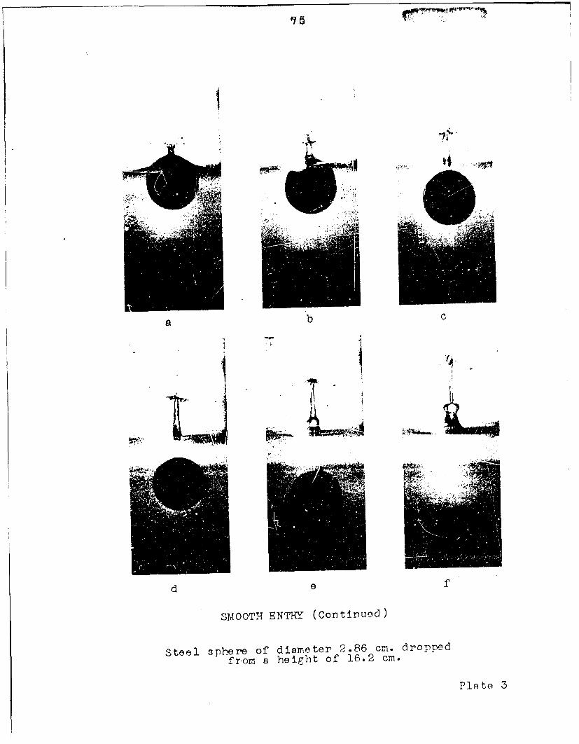
SMOOTHEENTRY (Continued)
Steel spliere of diamneter 2.86 cm. droppedfrom a he igh of 16.2 cm.
Plqto 3

77
0
CD
P44
0004
04

79
b
These pictures were taken b- r. Furle.-of the Morris Dam Group at California inst2tute o Techrnology.
P'•=. 5

81
ROJGH EN TI•Y
a b
c d
Steel ball, 5/8r dimreter, velocity 19.4 ft/sec.Pressure.above liquid = 20 cmi. mercury.
These pictures were taken b-. R. M. Davies
of the Engiineering Laboratory, Cazbrid:7e, Enzisr.
Plate 6

83
HIGH-SPEED ENTRY &HOWING COMPRESSIBILITY EFFECT3
Uo 8.84 x 104 cm/sec. A =0159 um. M 0 0.6 grams.
This photograph was taken by E. Newton Harvey
of Princeton University.
Plate 7