clearing the rf smog: making 802.11n robust to cross...
TRANSCRIPT
Clearing the RF Smog: Making 802.11n Robust toCross-Technology Interference
Shyamnath Gollakota† Fadel Adib† Dina Katabi† Srinivasan Seshan⋆†Massachusetts Institute of Technology
⋆Carnegie Mellon University
{gshyam, fadel, dina}@csail.mit.edu [email protected]
Recent studies show that high-power cross-technology interfer-ence is becoming a major problem in today’s 802.11 networks. De-vices like baby monitors and cordless phones can cause a wirelessLAN to lose connectivity. The existing approach for dealing withsuch high power interferers makes the 802.11 network switch chan-nels. However, the ISM band is becoming increasingly crowdedwith diverse high-power technologies, which makes it difficult tofind an interference-free channel.
This paper presents TIMO, a MIMO design that enables 802.11nto communicate in the presence of high-power cross-technologyinterference. Unlike existing MIMO designs, however, which as-sume that all concurrent transmissions belong to the same tech-nology, TIMO makes a radio exploit MIMO capability to treat ahigh-power signal from a different technology as if it were anotherstream from the same technology, hence enabling diverse technolo-gies to share the same frequency band. We have implemented aprototype of TIMO in GNURadio-USRP2 and showed that it en-ables 802.11n to communicate in the presence of interference frombaby monitors, cordless phones, and microwave ovens, transform-ing scenarios with a complete loss of connectivity to operationalnetworks.
1. INTRODUCTION
Cross-technology interference is emerging as a major problemfor 802.11 networks. Independent studies in 2010 by the FarpointGroup [8], BandSpeed [17], and Miercom [10] all show that high-power interferers like baby monitors and cordless phones can cause802.11n networks to experience a complete loss of connectivity.Other studies from Ofcom [7], Jupiter Research [1], and Cisco [14]report that such interferers are responsible for more than half of theproblems reported in customer networks. Today’s high-power non-WiFi sources in the ISM band include surveillance cameras, babymonitors, microwave ovens, digital and analog cordless phones, andoutdoor microwave links. Some of these technologies transmit in afrequency band as wide as 802.11, and all of them emit power that iscomparable or higher than 802.11 devices [17]. Further, the numberand diversity of such interferers is likely to increase over time dueto the proliferation of new technologies in the ISM band.
Traditional solutions that increase resilience to interference bymaking 802.11 fall down to a lower bit rate are ineffective against
Permission to make digital or hard copies of all or part of this work forpersonal or classroom use is granted without fee provided that copies arenot made or distributed for profit or commercial advantage and that copiesbear this notice and the full citation on the first page. To copy otherwise, torepublish, to post on servers or to redistribute to lists, requires prior specificpermission and/or a fee.SIGCOMM’11, August 15–19, 2011, Toronto, Ontario, Canada.Copyright 2011 ACM 978-1-4503-0797-0/11/08 ...$10.00.
high power cross technology interference. As a result, the mostcommon solution today is to hop away to an 802.11 channel thatdoes not suffer from interference [6, 38, 31, 32]. However, the ISMband is becoming increasingly crowded, making it difficult to findan interference-free channel. The lack of interference-free channelshas led WiFi device manufacturers [6, 11, 3] and researchers [29]todevelop signal classifiers that inform the 802.11 user about the rootcause of the problem (e.g., Bluetooth, microwave, baby monitor).However, these classifiers put the burden of addressing the problemon the user and cannot solve the problem on their own.
In this paper, we ask whether it is possible to use the MIMO capa-bility inherent to 802.11n to address high-power cross-technologyinterference. MIMO achieves most of its throughput gains by en-abling multiple concurrent streams (e.g., packets). Current MIMOdecoding, however, fails if any of these concurrent streams belongsto a different technology. Nonetheless, if MIMO can be made towork across technologies, a 3×3 802.11n transmitter can then treatthe signal from a baby monitor or microwave as one stream and stilldeliver two concurrent streams to its receiver.
The challenge in harnessing MIMO across different technolo-gies stems from the fact that MIMO decoding hinges on estimat-ing the channel between all transmit and receive antennas. Theseestimates rely on understanding the signal structure and assume aknown preamble. Hence, it has been infeasible to use MIMO acrossdifferent and potentially unknown technologies.
We present TIMO,1 an 802.11n receiver design that is robust tohigh-power cross-technology interference. TIMO introduces a newMIMO technique that enables a receiver to decode a signal of inter-est, even when the channel from other concurrent transmissions isunknown. The intuition underlying TIMO is best explained via anexample. Consider a pair of 2-antenna 802.11n nodes that want tocommunicate in the presence of a high power unknown interferer.Let s(t) be the signal of interest andi(t) the interference signal. The802.11n receiver node will receive the following signals on its twoantennas:
y1(t) = hii(t) + hss(t) (1)
y2(t) = h′
i i(t) + h′
ss(t), (2)
wherehi andh′
i are the channels from the interferer to the 802.11nreceiver, andhs andh′
s are the channels from the 802.11n sender tothe 802.11n receiver. The 802.11n receiver has to solve the aboveequations to obtain its signal of interests(t). It knows the receivedsamples,y1(t) andy2(t), and the channels from its transmitter,hs
and h′
s, (which can be computed in the presence of interferenceas described in §6.4). The receiver, however, cannot compute thechannels from the interferer,hi andh′
i , because it does not knowthe interferer’s signal structure or preamble. Hence, it is left with
1Technology Independent Multi-Output (TIMO) receiver design.
two equations in three unknowns (s(t), hii(t), andh′
i i(t))2, which it
cannot solve.Note that the receiver can cancel the interference if it knows the
interferer’s channel ratiohih′i
. In particular, the receiver can rewrite
equations 1 and 2 to express the signal of interest as:
s(t) =y1(t)− βy2(t)
hs − βh′s
for β =hi
h′
i
. (3)
The only unknown in the above equation isβ = hih′i
. Thus, though
the 802.11n receiver cannot compute the exact channels of the in-terferer, it can still cancel its interference using only its channelratio.
Still, how do we obtain this ratio given no support from the inter-ferer? The receiver can obtain the interferer’s channel ratio as fol-lows: Say that for some time instancet = t0, our transmitter sends aknown symbols(t0). Our receiver can then substitute in equations 1and 2 to obtain:
hi
h′
i
=y1(t0)− hss(t0)y2(t0)− h′
ss(t0), (4)
where all terms are known except for the ratiohih′i
. In §6, we de-
velop this idea further and eliminate the need for having the trans-mitter send a known symbol, which makes the scheme applicableto the existing 802.11n frames. We further generalize the solutionto address scenarios in which different frequencies have differentinterferers, or the interferer hops across frequencies.
A MIMO transmitter can also encode its signal using zero-forcing [36] such that it does not interfere with a concurrent trans-mission from a competing technology. However, using a similarcomputation to the above, we show that it is necessary to obtain theratio hs1
hs2, wherehs1 andhs2 are the channels from the MIMO trans-
mitter to the receiver of the competing technology. These channelscan only be estimated if the receiving node transmits data at somepoint, i.e., if the competing technology uses bidirectional commu-nication, e.g., a cordless phone. If this constraint is met, however,TIMO can be used not only to protect 802.11n networks from high-power interference, but also as a cognitive mechanism that enablesMIMO-based nodes to peacefully coexist in the same frequencyband with bidirectional non-MIMO nodes from a different tech-nology. In this case, the simpler non-MIMO nodes simply transmitbidirectionally, and the more complex MIMO nodes take on theburden of preventing interference. This approach can lead to a newform of spectrum sharing in which different technologies do notnecessarily have to find unoccupied bands and, in crowded envi-ronments, could instead occupy the same band thereby increasingspectral efficiency.
We have built a prototype of TIMO using 2-antenna USRP2radios [13]. We have evaluated our design in the presence of in-terference from three technologies: a microwave oven, an analogbaby monitor, and a DSSS cordless phone. We first use commercial802.11n cards and iperf [33] to transmit in the presence of theseinterferers. We find that, in our testbed, the cordless phone and thebaby monitor prevent 802.11 from establishing any connection, re-ducing its throughput to zero. The microwave, on the other hand,results in a throughput reduction of 35–90%. We replace the com-mercial 802.11n cards with our USRP2 nodes and repeat the ex-periment with and without TIMO. We find that in the absence ofTIMO, when the USRP2 nodes are less than 31 feet away fromthe cordless phone or the baby monitors, they cannot deliver anypackets. In contrast, in the presence of TIMO, and for the same
2We can lumpi(t) with the channel variable because we are notinterested in decoding the symbols of the interferer.
A
B
1
2
3
4
5 6 7 8 9
10
97 Feet
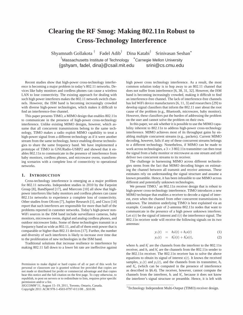
Figure 1—Testbed. A transmitter located at A is communicatingwith a receiver at B. The interferer is placed in one of the locations1 to 10.
locations, their throughput increases to 13-23 Mb/s. We also im-plement cross-technology zero-forcing and show that it enables aMIMO node to significantly reduce the packet loss at the receiverof a competing technology, with the reduction in packet loss beingas high as 14x in some locations.
2. IMPACT OF CROSS-TECHNOLOGY INTER-FERENCE ON 802.11N
We study the interaction between high-power interferers and802.11n and compare against the interaction between a low powerinterferer, Bluetooth, and 802.11n. We focus on three high-powertechnologies that are prevalent in today’s environments [7]: DSSScordless phones, baby monitors, and microwave ovens.
Experimental Setup: We use the Netgear N-300 USB-adapter andthe Netgear N-300 router as the 802.11n client and AP respectively.Both devices support 2× 2 MIMO. We place the AP and the clientat positions A and B in Fig. 1. In each run, we place the interfererat one of the marked locations in Fig. 1. Our experiments includeline-of-sight and non-line-of-sight situations, and show scenarios inwhich the interferer is within one foot of the 802.11n client as wellas 90 feet away from it. We run iperf on the two 802.11n deviceswith the 802.11n client acting as the iperf server. The AP sendsUDP packets for 2 minutes and logs the average throughput ob-served every 500 ms. In each location, we compute the observed802.11n throughput first when the interferer is turned OFF and nextwhen it is ON. Additionally, we use a USRP2 software radio tomonitor a 25 MHz bandwidth. The USRP2 simply logs the timesignal which we process offline to obtain the time and frequencycharacteristics of each interferer.
2.1 Digital Cordless PhoneWe experiment with the Uniden TRU 4465-2 DSSS cordless
handset system. The phone base and handset communicate usingdigital spread spectrum in the 2.4 GHz range. In each experiment,we fix the 802.11n AP and client at locations A and B and placeboth the cordless handset and the phone base at one of the locationsin the testbed, 5 cm away from each other.
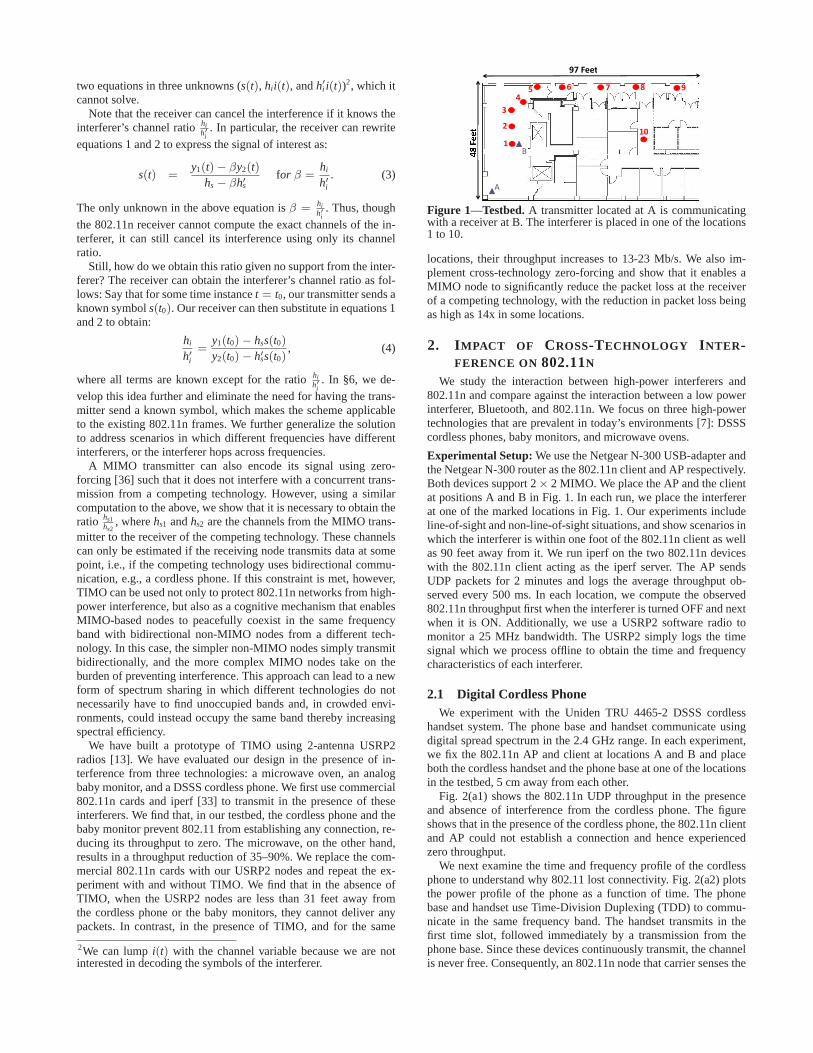
Fig. 2(a1) shows the 802.11n UDP throughput in the presenceand absence of interference from the cordless phone. The figureshows that in the presence of the cordless phone, the 802.11n clientand AP could not establish a connection and hence experiencedzero throughput.
We next examine the time and frequency profile of the cordlessphone to understand why 802.11 lost connectivity. Fig. 2(a2) plotsthe power profile of the phone as a function of time. The phonebase and handset use Time-Division Duplexing (TDD) to commu-nicate in the same frequency band. The handset transmits in thefirst time slot, followed immediately by a transmission from thephone base. Since these devices continuously transmit, the channelis never free. Consequently, an 802.11n node that carrier senses the
0 10 20 30 40 50 60 70 80
1 2 3 4 5 6 7 8 9 10
UD
P T
hrou
ghpu
t [M
bps]
Locations
With Cordless PhoneWithout Cordless Phone
0 2 4 6 8 10 12 14−80
−70
−60
−50
−40
−30
−20
Time (in msecs)
Pow
er P
rofil
e (d
Bm
)
Phone Base Handset
(a1) 802.11n UDP Throughput (a2) Time Profile (a3) Spectrogram(a) DSSS Cordless Phone
0
10
20
30
40
50
60
70
80
1 2 3 4 5 6 7 8 9 10
UD
P T
hrou
ghpu
t [M
bps]
Locations
With Baby MonitorWithout Baby Monitor
0 500 1000 1500 2000 2500 3000 3500 4000−80
−60
−40
−20
0
Time (in msecs)
Pow
er P
rofil
e (in
dB
m) Camera
turned ON
(b1) 802.11n UDP Throughput (b2) Time Profile (b3) Spectrogram(b) Baby Monitor
0
10
20
30
40
50
60
70
80
1 2 3 4 5 6 7 8 9 10
UD
P T
hrou
ghpu
t [M
bps]
Locations
With MicrowaveWithout Microwave
0 10 20 30 40 50 60−80
−60
−40
−20
0
Time (in msecs)
Pow
er P
rofil
e (d
Bm
)
Microwaveturned ON
ON Slot
OFF Slot
(c1) 802.11n UDP Throughput (c2) Time Profile (c3) Spectrogram(c) Microwave Oven
Figure 2—Characteristics of High Power Interferers in the ISM Band.
medium never gets the opportunity to transmit. Furthermore, sincethe phone transmits at about 25 mWatt [12], which is comparableto an 802.11 laptop, its interference continues even at distances asfar as 80 feet.
The phone’s spectrogram depicted in Fig. 2(a3) shows that thephone occupies a 4 MHz band. Typically, the phone picks one chan-nel out of 35 radio channels in the 2.407-2.478 GHz range. It stayson that channel as long as it does not experience persistent interfer-ence.
2.2 Baby Monitor
We experiment with the C-501 wireless monitoring toolkit. Thesystem consists of two units: a 2.4 GHz wireless camera that sup-ports up to 4 different channels (i.e., 2.414 GHz, 2.432 GHz,2.450 GHz and 2.468 GHz), and a wireless video receiver equippedwith a 640× 480 screen. As before, for every interferer locationin the testbed, we measure the 802.11n throughput with the cameraON and OFF, and plot the results in Fig. 2(b1). The figure showsthat the 802.11n client and AP could not establish a connection and,hence, could not exchange any packets for all tested interferer’s lo-cations.
We plot the time profile of the camera in Fig. 2(b2) and its fre-quency profile in Fig. 2(b3). The frequency profile shows that thebaby monitor occupies a relatively wide channel of 16 MHz. Fur-thermore, the time profile shows that the camera transmits contin-uously, thus hogging the medium completely. These observations,compounded with the fact that the camera transmits at a fairly highpower of 200 mW [2], explain the inability of 802.11n to obtain anythroughput.
2.3 Microwave OvensWe use the SHARP R-310CW microwave oven. Fig. 2(c1) shows
the observed 802.11n average throughput for different placement ofthe microwave. The figure shows that when the microwave is onefoot away (in location 1), 802.11n suffers a throughput reduction of90%. The 802.11n throughput improves as the microwave is movedaway from the AP and its client, and the throughput loss decreasesto 35% at the farthest location from the 802.11 client.
To understand this behavior, we plot the microwave’s power pro-file over time in Fig. 2(b2). The figure shows that the microwaveexhibits a periodic ON-OFF pattern, where an ON period lasts forabout 10 ms and an OFF period lasts for 6 ms. In addition to thisON-OFF pattern, the microwave exhibits a continuous low interfer-ence, as evident from the 10 dB increase in the noise level after themicrowave was turned on. The microwave time profile explains itsimpact on 802.11n. Specifically, at distant locations in our testbed,802.11n transmits during the OFF periods but refrains from trans-mitting during the ON periods because it senses the medium as oc-cupied. As a result, the throughput loss in such locations is about35%. In contrast, at close distances, the 10 dB increase in the noiselevel generated by the microwave creates substantial interferencefor 802.11n causing most packets to be dropped even during theOFF periods.
2.4 Frequency Hopping BluetoothFinally, we evaluate the interference generated by Bluetooth de-
vices. Bluetooth uses frequency hopping across a 79 MHz band inthe 2.402-2.480 GHZ range, occupying 1 MHz at any point in time.The most common devices use class 2 Bluetooth which transmits ata relatively low power of 2.5 mW [5].
0
10
20
30
40
50
60
70
80
1 2 3 4 5 6 7 8 9 10
UD
P T
hrou
ghpu
t [M
bps]
Locations
With BluetoothWithout Bluetooth
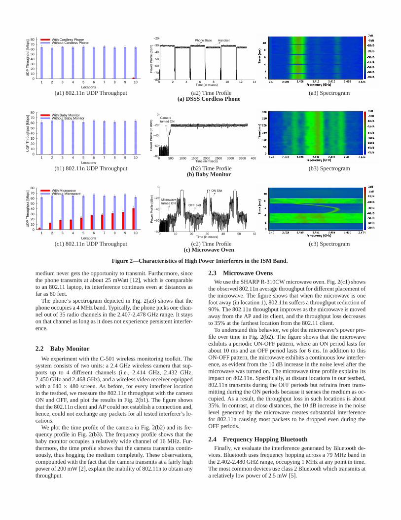
Figure 3—The impact of Bluetooth interference on 802.11n.2211111shshy +=
2221122shshy +=
1s
2s
12h
11h
h21
22h
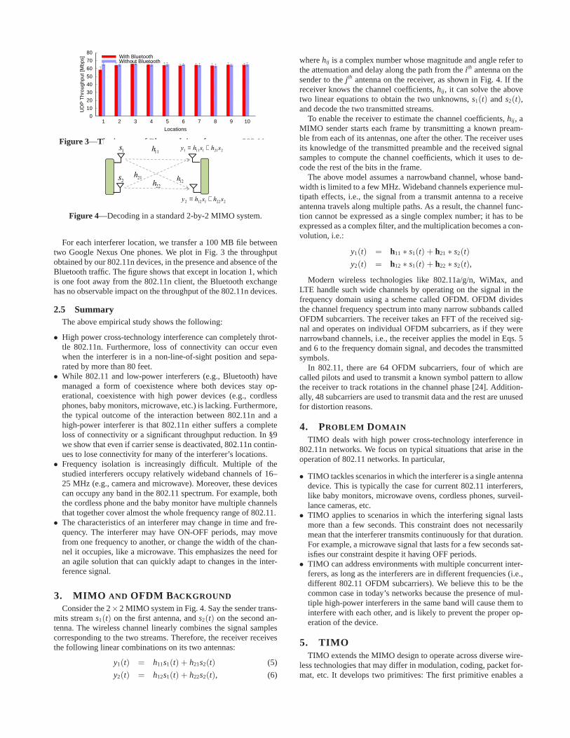
Figure 4—Decoding in a standard 2-by-2 MIMO system.
For each interferer location, we transfer a 100 MB file betweentwo Google Nexus One phones. We plot in Fig. 3 the throughputobtained by our 802.11n devices, in the presence and absence of theBluetooth traffic. The figure shows that except in location 1, whichis one foot away from the 802.11n client, the Bluetooth exchangehas no observable impact on the throughput of the 802.11n devices.
2.5 SummaryThe above empirical study shows the following:
• High power cross-technology interference can completely throt-tle 802.11n. Furthermore, loss of connectivity can occur evenwhen the interferer is in a non-line-of-sight position and sepa-rated by more than 80 feet.
• While 802.11 and low-power interferers (e.g., Bluetooth) havemanaged a form of coexistence where both devices stay op-erational, coexistence with high power devices (e.g., cordlessphones, baby monitors, microwave, etc.) is lacking. Furthermore,the typical outcome of the interaction between 802.11n and ahigh-power interferer is that 802.11n either suffers a completeloss of connectivity or a significant throughput reduction. In §9we show that even if carrier sense is deactivated, 802.11n contin-ues to lose connectivity for many of the interferer’s locations.
• Frequency isolation is increasingly difficult. Multiple of thestudied interferers occupy relatively wideband channels of 16–25 MHz (e.g., camera and microwave). Moreover, these devicescan occupy any band in the 802.11 spectrum. For example, boththe cordless phone and the baby monitor have multiple channelsthat together cover almost the whole frequency range of 802.11.
• The characteristics of an interferer may change in time and fre-quency. The interferer may have ON-OFF periods, may movefrom one frequency to another, or change the width of the chan-nel it occupies, like a microwave. This emphasizes the need foran agile solution that can quickly adapt to changes in the inter-ference signal.
3. MIMO AND OFDM BACKGROUND
Consider the 2×2 MIMO system in Fig. 4. Say the sender trans-mits streams1(t) on the first antenna, ands2(t) on the second an-tenna. The wireless channel linearly combines the signal samplescorresponding to the two streams. Therefore, the receiver receivesthe following linear combinations on its two antennas:
y1(t) = h11s1(t) + h21s2(t) (5)
y2(t) = h12s1(t) + h22s2(t), (6)
wherehij is a complex number whose magnitude and angle refer tothe attenuation and delay along the path from theith antenna on thesender to thejth antenna on the receiver, as shown in Fig. 4. If thereceiver knows the channel coefficients,hij, it can solve the abovetwo linear equations to obtain the two unknowns,s1(t) ands2(t),and decode the two transmitted streams.
To enable the receiver to estimate the channel coefficients,hij, aMIMO sender starts each frame by transmitting a known pream-ble from each of its antennas, one after the other. The receiver usesits knowledge of the transmitted preamble and the received signalsamples to compute the channel coefficients, which it uses to de-code the rest of the bits in the frame.
The above model assumes a narrowband channel, whose band-width is limited to a few MHz. Wideband channels experience mul-tipath effects, i.e., the signal from a transmit antenna to a receiveantenna travels along multiple paths. As a result, the channel func-tion cannot be expressed as a single complex number; it has to beexpressed as a complex filter, and the multiplication becomes a con-volution, i.e.:
y1(t) = h11 ∗ s1(t) + h21 ∗ s2(t)
y2(t) = h12 ∗ s1(t) + h22 ∗ s2(t),
Modern wireless technologies like 802.11a/g/n, WiMax, andLTE handle such wide channels by operating on the signal in thefrequency domain using a scheme called OFDM. OFDM dividesthe channel frequency spectrum into many narrow subbands calledOFDM subcarriers. The receiver takes an FFT of the received sig-nal and operates on individual OFDM subcarriers, as if they werenarrowband channels, i.e., the receiver applies the model in Eqs. 5and 6 to the frequency domain signal, and decodes the transmittedsymbols.
In 802.11, there are 64 OFDM subcarriers, four of which arecalled pilots and used to transmit a known symbol pattern to allowthe receiver to track rotations in the channel phase [24]. Addition-ally, 48 subcarriers are used to transmit data and the rest are unusedfor distortion reasons.
4. PROBLEM DOMAIN
TIMO deals with high power cross-technology interference in802.11n networks. We focus on typical situations that arise in theoperation of 802.11 networks. In particular,
• TIMO tackles scenarios in which the interferer is a single antennadevice. This is typically the case for current 802.11 interferers,like baby monitors, microwave ovens, cordless phones, surveil-lance cameras, etc.
• TIMO applies to scenarios in which the interfering signal lastsmore than a few seconds. This constraint does not necessarilymean that the interferer transmits continuously for that duration.For example, a microwave signal that lasts for a few seconds sat-isfies our constraint despite it having OFF periods.
• TIMO can address environments with multiple concurrent inter-ferers, as long as the interferers are in different frequencies (i.e.,different 802.11 OFDM subcarriers). We believe this to be thecommon case in today’s networks because the presence of mul-tiple high-power interferers in the same band will cause them tointerfere with each other, and is likely to prevent the proper op-eration of the device.
5. TIMOTIMO extends the MIMO design to operate across diverse wire-
less technologies that may differ in modulation, coding, packet for-mat, etc. It develops two primitives: The first primitive enables a
MIMO 802.11n pair to exchange packets in the presence of an un-known interference signal, as if the unknown interference were asingle-antenna 802.11 transmission. For example, an 802.11n AP-Client pair may use this primitive to correctly decode packets inthe presence of the ON periods of a microwave oven. The secondprimitive enables a MIMO node to transmit in the presence of anunknown bi-directional technology without hampering reception atthe receiver of the unknown technology. For example, an 802.11nnode may use this primitive to transmit in the presence of a cord-less phone without hampering the phone’s operation. The next fewsections describe these two primitives in detail and discuss wherethey may be applied.
6. DECODING IN THE PRESENCE OF CROSS-TECHNOLOGY INTERFERENCE
Consider a scenario in which two 802.11n nodes want to commu-nicate in the presence of high power cross-technology interference.How can the 802.11n receiver decode packets? For clarity, we willexplain the design in the context of a two-antenna 802.11n receiverdecoding a single 802.11n transmission, in the presence of an inter-ferer. The results extend to any number of antennas as we explainin the appendix.
In this case, the signal at the 2-antenna 802.11 receiver is the sumof the signal of interests(t) and the interference signali(t) afterconvolving them with their respective channels to the receiver, i.e.:
y1(t) = hi ∗ i(t) + hs ∗ s(t) (7)
y2(t) = h′
i ∗ i(t) + h′
s ∗ s(t), (8)
wherehi andh′
i are the interference channel impulse functions, andhs andh′
s are the signal channel impulse functions. We will explainTIMO’s decoding algorithm assuming the receiver knows the chan-nel of the signal of interest. In §6.4, we explain how the receiverobtains the channel function in the presence of interference.
Since the signal of interest (i.e., that of 802.11n) is an OFDM sig-nal, the receiver processes its input in the frequency domain. Thus,the receiver takes the FFT of the received signal as usual for OFDMsignals. For each OFDM subcarrier,j, the receiver obtains the fol-lowing equation:
Y1j = HijIj + HsjSj (9)
Y2j = H′
ijIj + H′
sjSj, (10)
where the terms in the above equations are the frequency versionof the terms in Eq. 7 and Eq. 8, for a particular OFDM subcarrier.Thus, the receiver can express the signal of interest as:
Sj =Y1j − βjY2j
Hsj − βjH′
sj
for βj =Hij
H′
ij
. (11)
All terms in the above equation are known at the receiver, except forthe interferer’s channel ratioβj =
Hij
H′
ij. The objective of the receiver
is to figure out the interferer’s channel ratio in an OFDM subcarrier,and use it to decode the signal of interest,Sj, in that subcarrier.
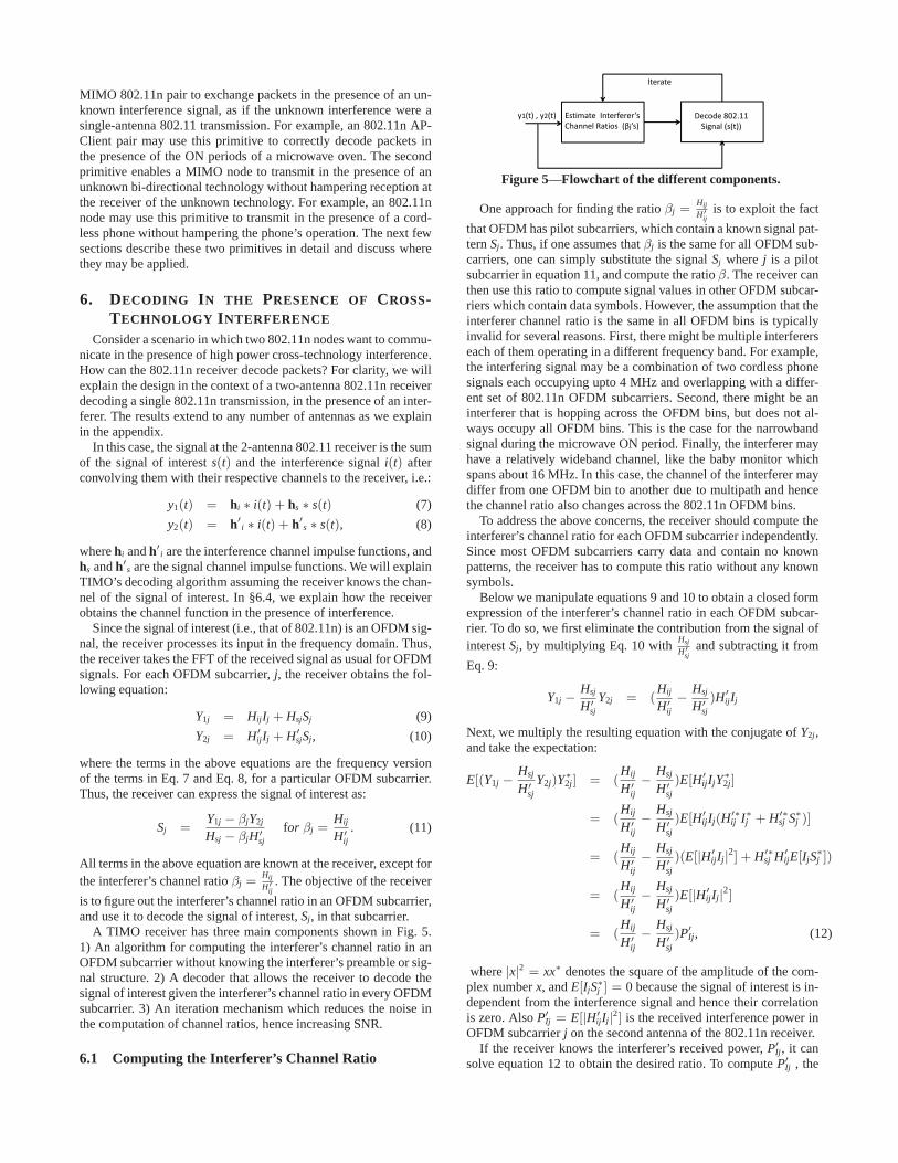
A TIMO receiver has three main components shown in Fig. 5.1) An algorithm for computing the interferer’s channel ratio in anOFDM subcarrier without knowing the interferer’s preamble or sig-nal structure. 2) A decoder that allows the receiver to decode thesignal of interest given the interferer’s channel ratio in every OFDMsubcarrier. 3) An iteration mechanism which reduces the noise inthe computation of channel ratios, hence increasing SNR.
6.1 Computing the Interferer’s Channel Ratio
Estimate Interferer’s
Channel Ratios (βj’s)
Decode 802.11
Signal (s(t))
y1(t) , y2(t)
Iterate
Figure 5—Flowchart of the different components.
One approach for finding the ratioβj =Hij
H′
ijis to exploit the fact
that OFDM has pilot subcarriers, which contain a known signal pat-ternSj. Thus, if one assumes thatβj is the same for all OFDM sub-carriers, one can simply substitute the signalSj wherej is a pilotsubcarrier in equation 11, and compute the ratioβ. The receiver canthen use this ratio to compute signal values in other OFDM subcar-riers which contain data symbols. However, the assumption that theinterferer channel ratio is the same in all OFDM bins is typicallyinvalid for several reasons. First, there might be multiple interfererseach of them operating in a different frequency band. For example,the interfering signal may be a combination of two cordless phonesignals each occupying upto 4 MHz and overlapping with a differ-ent set of 802.11n OFDM subcarriers. Second, there might be aninterferer that is hopping across the OFDM bins, but does not al-ways occupy all OFDM bins. This is the case for the narrowbandsignal during the microwave ON period. Finally, the interferer mayhave a relatively wideband channel, like the baby monitor whichspans about 16 MHz. In this case, the channel of the interferer maydiffer from one OFDM bin to another due to multipath and hencethe channel ratio also changes across the 802.11n OFDM bins.
To address the above concerns, the receiver should compute theinterferer’s channel ratio for each OFDM subcarrier independently.Since most OFDM subcarriers carry data and contain no knownpatterns, the receiver has to compute this ratio without any knownsymbols.
Below we manipulate equations 9 and 10 to obtain a closed formexpression of the interferer’s channel ratio in each OFDM subcar-rier. To do so, we first eliminate the contribution from the signal ofinterestSj, by multiplying Eq. 10 with
Hsj
H′
sjand subtracting it from
Eq. 9:
Y1j −Hsj
H′
sj
Y2j = (Hij
H′
ij
−Hsj
H′
sj
)H′
ijIj
Next, we multiply the resulting equation with the conjugate ofY2j,and take the expectation:
E[(Y1j −Hsj
H′
sjY2j)Y
∗
2j] = (Hij
H′
ij−
Hsj
H′
sj)E[H′
ijIjY∗
2j]
= (Hij
H′
ij−
Hsj
H′
sj)E[H′
ijIj(H′∗
ij I∗j + H′∗
sj S∗
j )]
= (Hij
H′
ij−
Hsj
H′
sj)(E[|H′
ijIj|2] + H′∗
sj H′
ijE[IjS∗
j ])
= (Hij
H′
ij−
Hsj
H′
sj)E[|H′
ijIj|2]
= (Hij
H′
ij−
Hsj
H′
sj)P′
Ij, (12)
where|x|2 = xx∗ denotes the square of the amplitude of the com-plex numberx, andE[IjS∗
j ] = 0 because the signal of interest is in-dependent from the interference signal and hence their correlationis zero. AlsoP′
Ij = E[|H′
ijIj|2] is the received interference power in
OFDM subcarrierj on the second antenna of the 802.11n receiver.If the receiver knows the interferer’s received power,P′
Ij, it cansolve equation 12 to obtain the desired ratio. To computeP′
Ij , the
receiver goes back to equation 10 and multiplies it by its conjugate,and takes the expectation, i.e.:
E[Y2jY∗
2j] = E[(H′
ijIj + H′
sSj)(H′
ijIj + H′
sSj)∗]
= E[|H′
ijIj|2] + E[|H′
sSj|2]
= P′
Ij + P′
Sj, (13)
whereP′
Sj is the power of the signal of interest on the second an-tenna in the jth OFDM subcarrier. Again, to reach Eq. 13 we haveexploited the fact that the interference signal and the signal of in-terest are independent of each other.
We can solve Eq. 12 and Eq. 13 together to obtain the interfererchannel ratio:
βj =Hij
H′
ij
=E[(Y1j −
Hsj
H′
sjY2j)Y∗
2j]
E[|Y2j|2]− P′
Sj
+Hsj
H′
sj
. (14)
This equation enables the 802.11 receiver to compute the inter-ferer’s channel ratio without any known symbols, simply by sub-stituting the power and the channel ratio fors(t).
It is important to note that the above derivation assumes that ex-pectations can be computed by taking averages. The accuracy ofthis estimate increases as one averages over more signal symbols.In §6.3 we will discuss how we can obtain a good accuracy withoutaveraging over many symbols.
6.2 Decoding the Signal of InterestOnce the 802.11n receiver has an estimate of the interferer’s
channel ratio,βj, in the various OFDM subcarriers, it proceeds todecode its own signal of interest. One way to decode the signalwould be to substituteβj in equation 11 to computeSj in the fre-quency domain. This approach works well when the interferer is anarrowband signal, like a cordless phone. However, it has low ac-curacy in scenarios where the interferer has a relatively widebandchannel, like a baby monitor that spans 16 MHz.
The reason for this is that wideband signals suffer from multipatheffects. Specifically, the signal travels from the sender to the re-ceiver along different paths, with different delays. As a result, at anyinstance in time, the receiver receives multiple copies of the samesignal with different relative delays. This leads to inter-symbol in-terference (ISI) which mathematically convolves the time-domainsignal with the channel on each of the paths it traverses.
To deal with ISI, an OFDM transmitter inserts a cyclic prefixbetween consecutive symbols. The receiver discards the cyclic pre-fix and takes the remaining signal, thus eliminating any interfer-ence from adjacent symbols. This, however, does not work whenwe have a wideband interferer like the baby monitor. First, its sig-nal may not have a cyclic prefix. Second, even if it does, as notedby past work on concurrent 802.11n transmissions [35], it is un-likely that the cyclic prefixes of the two devices are synchronized,in which case the receiver cannot take a single FFT that eliminatesISI for both.
The above discussion means that in the frequency domain, theinterferer’s signal,Ij, will experience ISI which would add noise.As a result, equations 9 and 10 have additional noise terms due toISI. While this is not a problem for the channel ratio estimationsince one can average across more samples to obtain an accurateestimate ofβj; this additional noise would reduce the SNR for thesignal of interest and, hence, affect its throughput.
The solution to the ISI problem is, however, simple. The 802.11nreceiver needs to decode the signal of interests(t) by eliminatinginterference in the time domain. Here, ISI is simply a convolutionwith a filter, which can be removed by applying the inverse filter(i.e., an equalizer). Thus, we consider again the initial time domain
Eqs. 7 and 8 which describe the signal at the 2-antenna 802.11nreceiver:
y1(t) = hi ∗ i(t) + hs ∗ s(t) (15)
y2(t) = h′
i ∗ i(t) + h′
s ∗ s(t), (16)
We want to find a filter,h, such that:
h ∗ h′
i = hi
Given such a filter, the receiver can convolveh with Eq. 16 andsubtract the resulting equation from Eq. 15 to eliminatei(t) andobtain an equation ins(t), which it can decode using a standard802.11 decoder.3
The above filter can be represented in the frequency domain as:
HjH′
ij = Hij ⇒ Hj =Hij
H′
ij
= βj
Thus, we can obtain the desired filter by taking the IFFT of theinterferer channel ratios computed in §6.1.
To summarize, the 802.11n receiver first moves the received sig-nal to the frequency domain where it computes the interferer chan-nel ratios using equation 14 while averaging over multiple samplesto reduce the ISI and noise. Then, it transforms the interferer chan-nel ratio into a time domain filter by taking IFFT. Finally, it usesthe filter to eliminate the interference signal in the time domain.The receiver can now take this interference free signal and decodeits signal of interest using a standard 802.11 decoder.
6.3 Iterating to Increase AccuracyThe algorithm in §6.1 computes expectations by taking averages
over multiple OFDM symbols. A packet however may not haveenough OFDM symbols to obtain a highly accurate estimate. Alsoaveraging over multiple packets will reduce TIMO’s ability to dealwith a dynamic interferer. Thus, in this section we are interested inobtaining an accurate estimate of the interferer’s channel ratio,βj,using only a few OFDM symbols.
To increase the accuracy of the estimate without much averaging,the receiver iterates over the following two steps:
Initialization: The receiver obtains a rough estimate ofβj by aver-aging over a limited number of OFDM symbols.
Step 1: The receiver uses its estimate ofβj to obtain the signal,s(t), as in §6.2. The receiver then decodess(t) using the standarddecoder to obtain the transmitted bits.
Step 2: The receiver re-modulates the decoded bits to obtain anestimate ofs(t), which we call s(t). The receiver convolvess(t)with the channel functions and subtracts the results fromy1(t) andy2(t). Thus, we obtain the following:
y1(t) = hi ∗ i(t) + hs ∗ (s(t)− s(t))
y2(t) = h′
i ∗ i(t) + h′
s ∗ (s(t)− s(t)).
The receiver then obtains a new estimate forβj while treating(s(t)− s(t)) as the new signal of interest.
After iterating between Step 1 and 2 for two or three times, thereceiver obtains an accurate estimate of the interferer’s channel ra-tio βj, which it uses to decode signals(t).
The reason why the above algorithm works is that in each iter-ation, the signal of interest used in STEP 2,(s(t) − s(t)), has asmaller magnitude. Since, in STEP 2, the receiver is focused on es-timating the interferer’s ratio, the signal of interest plays the role3As described in §3, such a decoder would apply FFT and decodein the frequency domain.
of noise; reducing this signal’s magnitude increases the accuracy ofthe ratio estimate. This higher accuracy in the ratioβj percolates tothe estimate ofs(t) in STEP 1. Consequently, the decoded bits aremore accurate and lead to even smaller difference betweens(t) ands(t), and hence an even more accurateβj.
6.4 Estimating the 802.11n Channel FunctionsSo far, we have assumed that the 802.11n receiver knows the
channel functions of the signal of interest,Hsj andH′
sj. To computethese functions we distinguish between two cases. First, the signalof interest starts before the interference in which case the receivercan use the 802.11 preamble to compute the channel, as usual. Sec-ond, the interference signal starts before the signal of interest. Inthis case, the receiver can easily compute the interferer’s channelratio βj =
Hij
H′
ijby taking the ratio of the signals it receives on its
two antennasY1j = HijIj andY2j = H′
ijIj. Once the receiver knowsthe interferer’s channel ratio, it computes the equalization filter de-scribed in §6.2 and uses it to eliminate the interference signal. Thereceiver can then use the 802.11n preamble to compute the channelas usual.
Two points are worth noting: First, while it is easy to computethe interferer’s channel ratios when the interferer is alone on themedium, this approach does not eliminate the need to continuetracking the interferer’s channel ratio using the algorithm in §6.1. Inparticular, the channel ratio may change as the interferer moves to adifferent frequency, as in the narrowband phase of a microwave sig-nal, or it might change for a mobile interferer, as with the cordlessphone.
Second, the above scheme will miss in scenarios in which theinterference and the 802.11n signal starts during the same OFDMsymbol. This event has a low probability, and the resulting packetloss is minor in comparison to the packet loss observed withoutTIMO. When such an event occurs the packet will be retransmittedby its sender as usual.
6.5 Finding the Interference BoundariesEstimating the interferer’s channel ratio,βj, using Eq. 14 re-
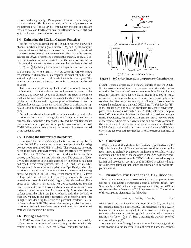
quires the 802.11n receiver to compute the expectations by takingaverages over multiple OFDM symbols. This averaging, however,needs to be done only over symbols that are affected by interfer-ence. Thus, the 802.11n receiver needs to determine where, in apacket, interference starts and where it stops. The question of iden-tifying the sequence of symbols affected by interference has beenaddressed in few recent systems, like PPR [25] and SoftRate [37].Our approach follows the same principles. Specifically, when theinterference signal starts, it causes a dramatic increase in decodingerrors. As shown in Fig. 6(a), these errors appear at the PHY layeras large differences between the received symbol and the nearestconstellation points in the I and Q diagram. We refer to these differ-ences as soft errors. Thus, for each OFDM subcarrier, the 802.11nreceiver computes the soft-error, and normalizes it by the minimumdistance of the constellation. As shown in Fig. 6(b), when the in-terferer starts, the soft errors jumps; when it ends, they go back totheir low values. In our implementation we consider a jump thatis higher than doubling the errors as a potential interferer, i.e., in-terference above 3 dB. This means that we might miss low powerinterferers, but such interferers can be dealt with using traditionalmethods like reducing the bit rate.
6.6 Putting it togetherA TIMO receiver first performs packet detection as usual by
looking for jumps in received power (using standard window de-tection algorithm [24]). Then, the receiver computes the 802.11
Received Symbol
Decoded Symbol
Soft Error
(a) Soft-errors in a 4QAM Constellation.
0 20 40 60 80 100 120 140 1600
0.2
0.4
0.6
0.8
1
1.2
OFDM symbol #
Nor
mal
ized
Sof
t Err
or
Interferencestarts
Interferencestops
(b) Soft-errors with Interference.
Figure 6—Soft errors increase in the presence of interference.
preamble cross-correlation, in a manner similar to current 802.11.If the cross-correlation stays low, the receiver works under the as-sumption that the signal of interest may start later. Hence, it com-putes the channel ratios for the signal though it is not its signalof interest. On the other hand, if the cross-correlation spikes, thereceiver identifies the packet as a signal of interest. It continues de-coding the packet using a standard OFDM and Viterbi decoder [15].If the packet does not pass the checksum test, the receiver com-putes the soft-errors as described in §6.5. If the soft-errors jump byover 3 dB, the receiver initiates the channel ratio estimation algo-rithm. Specifically, for each OFDM bin, the TIMO decoder startsat the symbol where the soft errors jump and proceeds to computethe interference channel ratios in an iterative manner as describedin §6.3. Once the channel ratios are estimated for each OFDM sub-carrier, the receiver uses the decoder in §6.2 to decode its signal ofinterest.
6.7 ComplexityWhile past work that deals with cross-techology interference [6,
34] typically employs different mechanisms for different technolo-gies, TIMO is technology agnostic and hence its complexity staysconstant as the number of technologies in the ISM band increases.Further, the components used in TIMO such as correlation, equal-ization and projection, are also used in MIMO receivers (thoughfor a different purpose), and hence are amenable to hardware im-plementations.
7. ENSURING THE INTERFERER CAN DECODE
A MIMO transmitter can also encode its signal to prevent inter-ference to a competing transmission from a different technology.Specifically, leti(t) be the competing signal ands1(t) ands2(t) thetwo streams that a 2-antenna 802.11n node transmits. The receiverof the competing signal gets the following:
z(t) = hii(t) + hs1s1(t) + hs2s2(t), (17)
wherehi refers to the channel from its transmitter andhs1 andhs2 arethe channels from the 2-antenna 802.11n transmitter. The 802.11ntransmitter can cancel its signal at the receiver of the competingtechnology by ensuring that the signals it transmits on its two anten-nas satisfys2(t) = − hs1
hs2s1(t). Such a technique is typically referred
to as zero-forcing [36].We note that zero forcing does not require the knowledge of the
exact channels to the receiver. It is sufficient to know the channel
ratios to zero out the signal at some receiver. This is crucial since forcross technology scenarios it is hard to estimate the exact channelfunctions.
But how does the 802.11n transmitter compute the channel ra-tio to the interferer’s receiver? If the interfering technology is bi-directional in the frequency of interest, then our 802.11n nodes canuse the interference caused by the receiver’s response to computethe channel ratio from the receiver to itself. This can be done byleveraging the algorithm in §6.1, despite differences in technol-ogy. The required ratio, however, describes the channels in the op-posite direction, i.e., from our 802.11n transmitter to the interfer-ing receiver. Wireless channels, however, exhibit reciprocity, i.e.,the channel function in the forward and backward direction is thesame. Reciprocity is a known physical property that has been val-idated empirically by multiple studies [21, 39, 28].4 Using reci-procity one can compute the required channel ratio. Once the ratiois computed, the transmitter can perform zero-forcing. We note thatsince it is hard to synchronize wideband cross-technology interfer-ers with 802.11, to avoid ISI we perform zero-forcing by using atime-domain equalizer similar to §6.2.
Thus, zero-forcing combined with our algorithm for estimatingthe interferer’s channel ratio provide a new primitive that enablesa MIMO node to transmit in the presence of a different technol-ogy without hampering reception of that technology. This primitive,however, requires the competing technology to be bidirectional, i.e.,the competing receiver acks the signal or transmits its own mes-sages, like a cordless phone.
If the technology is bidirectional, then the MIMO transmitter canlearn the channel to the communicating node pair, using the inter-ference they create. The MIMO transmitter then alternates betweennulling its signal at the two communicating nodes. For example, inthe case of a cordless phone, the 802.11 transmitter has to switchbetween nulling its signal at the handset and nulling its signal atthe base. In the case of the cordless phone, the switching time isconstant, and for the tested phone it is 2.25 ms. Even if the switch-ing time is not constant, as long as the pattern of the interference ispersistent, i.e., (one data packet, followed by one ack), the MIMOnode can monitor the medium and immediately switch every timethe medium goes idle.
On the other hand, if the receiver of the competing technologyis not bidirectional, an 802.11n device has no way to compute itschannel ratio, and hence cannot cancel its signal at the receiver ofthe competing technology. The impact of such interference will de-pend on the competing technology. For example, interference doesnot hamper a microwave oven function. Also, analog devices (e.g.,an analog camera) have some level of resistance to interferencewhich causes smooth degradation in their signal, and while theysuffer from interference, they can still function if the interferer isnot in close proximity (see §9).
In general, our objective is to create a form of coexistence be-tween 802.11n and high-power interferers that approaches the co-existence it enjoys with low-power devices like Bluetooth, wherethe two technologies may interferer if they are in close proximitybut the interference is limited and does not cause either device tobecome completely dysfunctional. Unidirectional devices which donot sense the medium or use any feedback from their receiver tendto show some level of resistance to interference. Hence, even if the802.11n node did not cancel its interference at their receiver, they
4To use it in our system, one needs to calibrate the effect of thehardware before applying reciprocity. This calibration, however, isdone once for the hardware. Furthermore, an 802.11n transmittercan perform this task without the help of any other node becauseit merely involves taking the difference between the two transmitchains attached to its two antennas.
can still support some level of coexistence, as long as the 802.11ncan protect itself from their interference.
8. IMPLEMENTATION
We have built a prototype of TIMO using the USRP2 radio plat-form and the GNURadio software package. A 2× 2 MIMO sys-tem is built using two USRP2 radio-boards connected via an ex-ternal clock [9]. Each USRP2 is configured to span a 10 MHzchannel by setting both the interpolation rate and decimation rateto 10. The resulting MIMO node runs a PHY layer similar to thatof 802.11n, i.e., it has 64 OFDM subcarriers, a modulation choiceof BPSK, 4QAM, 16QAM, or 64QAM, and punctured convolutioncodes with standard 802.11 code rates [15]. Since we operate at halfthe 802.11 bandwidth, the possible bit rates span 3 to 27Mbps.
We modify the receiver MIMO decoding algorithm to incor-porate TIMO (summarized in §6.6). We also implemented zero-forcing at the MIMO transmitters. To work with cross-technologyinterference, the transmitter first computes the channel ratios andthen uses them for zero forcing (as described in §7).
9. PERFORMANCE EVALUATION
We evaluate TIMO with three high-power interferers: a DSSScordless phone, a microwave oven, and a baby monitor.
9.1 Cordless PhoneAgain, we use the Uniden TRU 4465-2 cordless phone as the
interferer. We also use the same testbed in Fig. 1.
Addressing Cross-Technology Interference: We first evaluateTIMO’s ability to help 802.11n nodes operate in the presence ofhigh power cross-technology interference. We place two USRP-based 802.11n nodes in locations A and B in Fig. 1. In each run,we place the cordless phone system in one of the 10 interferer loca-tions in Fig. 1. We transfer a 20 MB file between the 802.11n pairat the best bitrate for the channel in the presence of interferencefrom the cordless phone. This rate is determined by initially tryingall the possible bitrates and choosing the one which yields the high-est throughput for the rest of the run. The 802.11 receiver logs thereceived samples and processes them both with and without TIMO.
Note that in contrast to the experiments done with commercial802.11n nodes, the USRP implementation of 802.11n does not usecarrier sense. Carrier sense is hard to implement in software due toits strict timing requirements. This constraint however can be ben-eficial. In particular, the lack of carrier sense provides insight intowhether the throughput loss of commercial 802.11n is due to thenodes sensing the phone’s signal and abstaining from transmitting,or due to their packets being corrupted by interference.
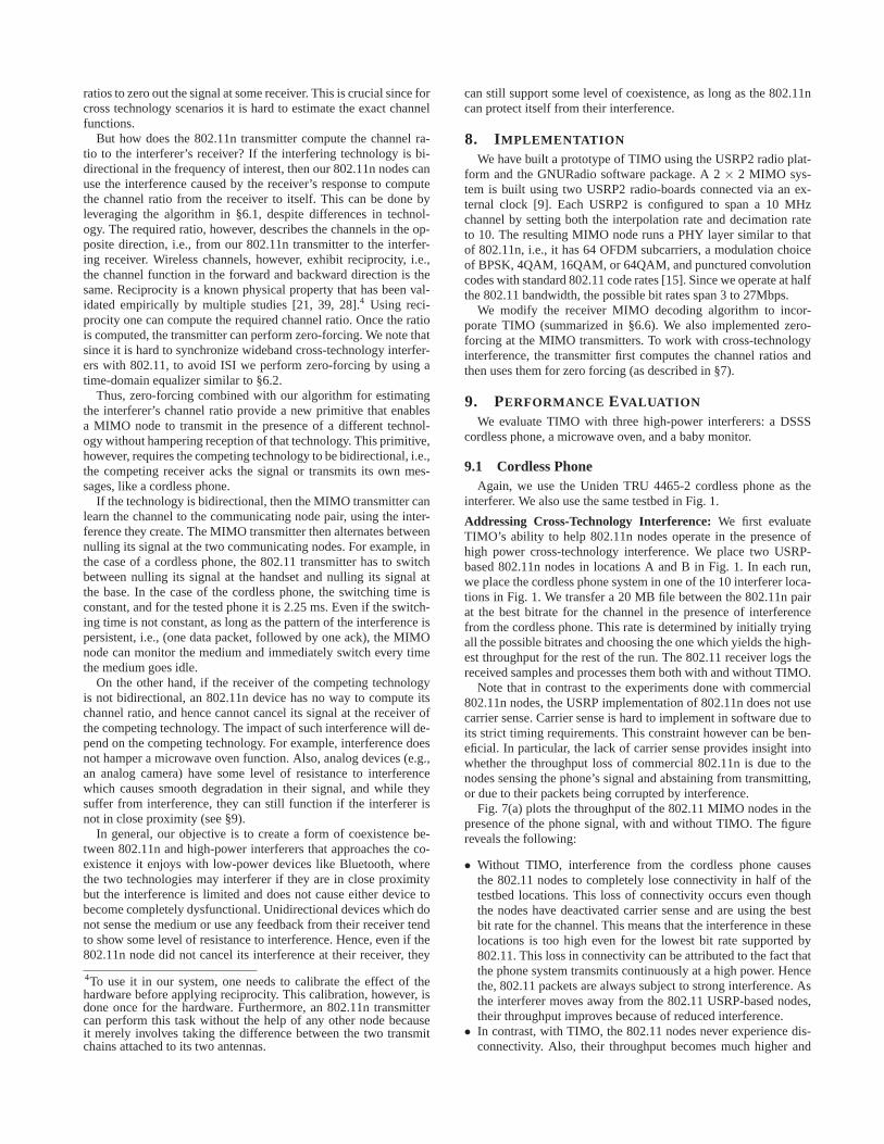
Fig. 7(a) plots the throughput of the 802.11 MIMO nodes in thepresence of the phone signal, with and without TIMO. The figurereveals the following:
• Without TIMO, interference from the cordless phone causesthe 802.11 nodes to completely lose connectivity in half of thetestbed locations. This loss of connectivity occurs even thoughthe nodes have deactivated carrier sense and are using the bestbit rate for the channel. This means that the interference in theselocations is too high even for the lowest bit rate supported by802.11. This loss in connectivity can be attributed to the fact thatthe phone system transmits continuously at a high power. Hencethe, 802.11 packets are always subject to strong interference. Asthe interferer moves away from the 802.11 USRP-based nodes,their throughput improves because of reduced interference.
• In contrast, with TIMO, the 802.11 nodes never experience dis-connectivity. Also, their throughput becomes much higher and
0
5
10
15
20
25
30
1 2 3 4 5 6 7 8 9 10
Thr
ough
put [
Mbp
s]
Locations
Without TIMOWith TIMO
0
0.2
0.4
0.6
0.8
1
1 2 3 4 5 6 7 8 9 10
Pac
ket L
oss
Rat
e
Locations
With 802.11Without 802.11With TIMO-equipped 802.11
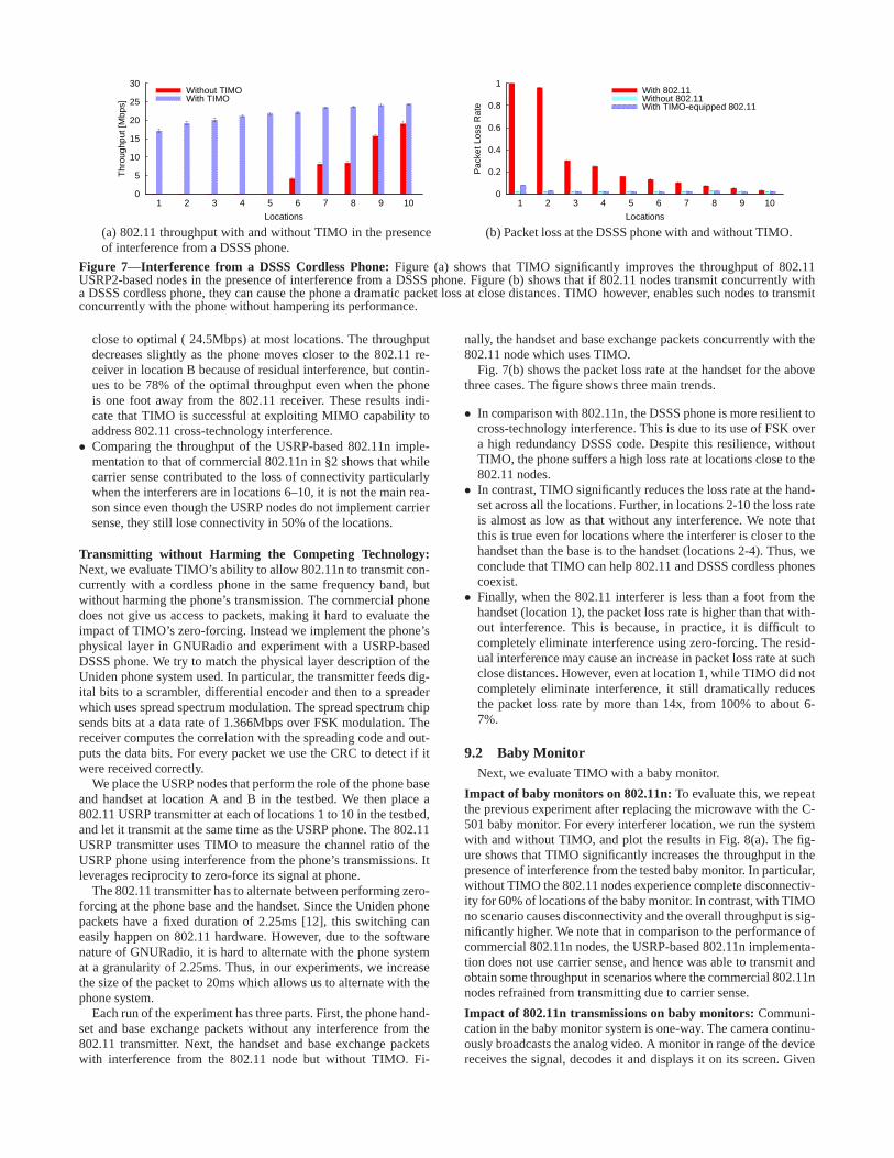
(a) 802.11 throughput with and without TIMO in the presenceof interference from a DSSS phone.
(b) Packet loss at the DSSS phone with and without TIMO.
Figure 7—Interference from a DSSS Cordless Phone: Figure (a) shows that TIMO significantly improves the throughput of 802.11USRP2-based nodes in the presence of interference from a DSSS phone. Figure (b) shows that if 802.11 nodes transmit concurrently witha DSSS cordless phone, they can cause the phone a dramatic packet loss at close distances. TIMO however, enables such nodes to transmitconcurrently with the phone without hampering its performance.
close to optimal ( 24.5Mbps) at most locations. The throughputdecreases slightly as the phone moves closer to the 802.11 re-ceiver in location B because of residual interference, but contin-ues to be 78% of the optimal throughput even when the phoneis one foot away from the 802.11 receiver. These results indi-cate that TIMO is successful at exploiting MIMO capability toaddress 802.11 cross-technology interference.
• Comparing the throughput of the USRP-based 802.11n imple-mentation to that of commercial 802.11n in §2 shows that whilecarrier sense contributed to the loss of connectivity particularlywhen the interferers are in locations 6–10, it is not the main rea-son since even though the USRP nodes do not implement carriersense, they still lose connectivity in 50% of the locations.
Transmitting without Harming the Competing Technology:Next, we evaluate TIMO’s ability to allow 802.11n to transmit con-currently with a cordless phone in the same frequency band, butwithout harming the phone’s transmission. The commercial phonedoes not give us access to packets, making it hard to evaluate theimpact of TIMO’s zero-forcing. Instead we implement the phone’sphysical layer in GNURadio and experiment with a USRP-basedDSSS phone. We try to match the physical layer description of theUniden phone system used. In particular, the transmitter feeds dig-ital bits to a scrambler, differential encoder and then to a spreaderwhich uses spread spectrum modulation. The spread spectrum chipsends bits at a data rate of 1.366Mbps over FSK modulation. Thereceiver computes the correlation with the spreading code and out-puts the data bits. For every packet we use the CRC to detect if itwere received correctly.
We place the USRP nodes that perform the role of the phone baseand handset at location A and B in the testbed. We then place a802.11 USRP transmitter at each of locations 1 to 10 in the testbed,and let it transmit at the same time as the USRP phone. The 802.11USRP transmitter uses TIMO to measure the channel ratio of theUSRP phone using interference from the phone’s transmissions. Itleverages reciprocity to zero-force its signal at phone.
The 802.11 transmitter has to alternate between performing zero-forcing at the phone base and the handset. Since the Uniden phonepackets have a fixed duration of 2.25ms [12], this switching caneasily happen on 802.11 hardware. However, due to the softwarenature of GNURadio, it is hard to alternate with the phone systemat a granularity of 2.25ms. Thus, in our experiments, we increasethe size of the packet to 20ms which allows us to alternate with thephone system.
Each run of the experiment has three parts. First, the phone hand-set and base exchange packets without any interference from the802.11 transmitter. Next, the handset and base exchange packetswith interference from the 802.11 node but without TIMO. Fi-
nally, the handset and base exchange packets concurrently with the802.11 node which uses TIMO.
Fig. 7(b) shows the packet loss rate at the handset for the abovethree cases. The figure shows three main trends.
• In comparison with 802.11n, the DSSS phone is more resilient tocross-technology interference. This is due to its use of FSK overa high redundancy DSSS code. Despite this resilience, withoutTIMO, the phone suffers a high loss rate at locations close to the802.11 nodes.
• In contrast, TIMO significantly reduces the loss rate at the hand-set across all the locations. Further, in locations 2-10 the loss rateis almost as low as that without any interference. We note thatthis is true even for locations where the interferer is closer to thehandset than the base is to the handset (locations 2-4). Thus, weconclude that TIMO can help 802.11 and DSSS cordless phonescoexist.
• Finally, when the 802.11 interferer is less than a foot from thehandset (location 1), the packet loss rate is higher than that with-out interference. This is because, in practice, it is difficult tocompletely eliminate interference using zero-forcing. The resid-ual interference may cause an increase in packet loss rate at suchclose distances. However, even at location 1, while TIMO did notcompletely eliminate interference, it still dramatically reducesthe packet loss rate by more than 14x, from 100% to about 6-7%.
9.2 Baby MonitorNext, we evaluate TIMO with a baby monitor.
Impact of baby monitors on 802.11n: To evaluate this, we repeatthe previous experiment after replacing the microwave with the C-501 baby monitor. For every interferer location, we run the systemwith and without TIMO, and plot the results in Fig. 8(a). The fig-ure shows that TIMO significantly increases the throughput in thepresence of interference from the tested baby monitor. In particular,without TIMO the 802.11 nodes experience complete disconnectiv-ity for 60% of locations of the baby monitor. In contrast, with TIMOno scenario causes disconnectivity and the overall throughput is sig-nificantly higher. We note that in comparison to the performance ofcommercial 802.11n nodes, the USRP-based 802.11n implementa-tion does not use carrier sense, and hence was able to transmit andobtain some throughput in scenarios where the commercial 802.11nnodes refrained from transmitting due to carrier sense.
Impact of 802.11n transmissions on baby monitors: Communi-cation in the baby monitor system is one-way. The camera continu-ously broadcasts the analog video. A monitor in range of the devicereceives the signal, decodes it and displays it on its screen. Given

0
5
10
15
20
25
30
1 2 3 4 5 6 7 8 9 10
Thr
ough
put [
Mbp
s]
Locations
Without TIMOWith TIMO
0
5
10
15
20
25
30
35
40
1 2 3 4 5 6 7 8 9 10
PS
NR
[dB
]
Locations
With 802.11Without 802.11
(a) 802.11 throughput with and without TIMO in the presenceof interference from a baby monitor.
(b) Camera PSNR. (above 20 dB is watchable; above 25is good [40]).
Figure 8—Interference from a Baby Monitor: Figure (a) shows that TIMO significantly improves the throughput of 802.11 nodes in thepresence of interference from a baby monitor. Figure (b) shows thatwhile TIMO cannot cancel its signal at the camera’s receiver because ituse a unidirectional communication, the impact of interference on the camera’s signal is watchable in all locations but the two closest to the802.11 nodes.
no signal from the video receiver, TIMO is limited in its ability toprotect the transmitted video. Thus, we would like to check how thecamera is affected by interference from our 802.11 implementation(which use the same power level as a laptop, i.e., about 30 mW).
To do so, we place the camera and its video receiver in locationsA and B in the testbed. We move the 802.11-USRP node across thevarious interferer locations, and at each location, we ensure it in-terferes with the camera’s transmission. We compare the receivedvideo quality with and without interference from 802.11. We mea-sure video quality using PSNR, which is a standard video metric.A PSNR of less than 20 dB is hard to watch, whereas PSNRs inthe range 25–30 dB are typical. The PSNR can be computed onlywith respect to the original video. However, the camera does notprovide us access to the original video before transmission over thewireless medium. To obtain a video baseline, we focus the cameraon the same static image for all experiments, and make it transmitthe same frame 1000 times. Then, we take the average pixel valuein these 1000 versions of the same frame and consider this to bethe ground truth. All experiments are run with the camera focusedon the same picture so that they can be compared with this groundtruth.
Fig. 8(b) shows the PSNR of the received video both with andwithout interference from our USRP-based 802.11 implementation.The figure shows that at the closest two locations, which are lessthan 6 feet away from the 802.11 interferer, the video is not watch-able. However, for the rest of the locations, the video quality stayswatchable. Further, for seven out of the ten testbed locations, thevideo PSNR hardly changes from its value without interference.This is expected because devices that blast the medium withoutchecking for interference or without any feedback tend to be rel-atively resilient to some level of interference.
We note that since the monitoring system is uni-directional,TIMO cannot cancel its signal at potential video receivers; hence,we observe that interference degrades the monitoring system’s per-formance at nearby locations. However, in contrast to the currentmode of operation, where 802.11 loses connectivity in most loca-tions due to interference, TIMO is an improvement over the statusquo because it reduces the range of interference to close-by loca-tions. This moves the system to a scenario where the two technolo-gies enjoy some level of coexistence, which despite being far fromoptimal, is more acceptable than the current situation.
9.3 Microwave Oven
We evaluate TIMO’s performance in the presence of interferencefrom the microwave oven used in the experiments in §2. We repeatthe experiment we conducted with the cordless phone, where weplace the USRP-based 802.11 devices in locations A and B, and letthem exchange traffic with the microwave on and off. We perform
0
5
10
15
20
25
30
1 2 3 4 5 6 7 8 9 10
Thr
ough
put [
Mbp
s]
Locations
Without TIMOWith TIMO
Figure 9—802.11 throughput with interference from a Mi-crowave Oven: The figure shows that TIMO increases resilienceto microwave interference.
the experiment for each of the ten interferer locations in the testbed.In each run, the 802.11 transmitter uses the best bitrate as in §9.1.
Fig. 9 shows the average throughput and standard deviation, withand without TIMO. Without TIMO, the performance of the USRP2nodes is relatively similar to that of the commercial 802.11n nodes.Specifically, at short distances, the throughput is very low due toincreased interference. As the microwave is moved away, the nodesstart getting packet through during the OFF periods of the mi-crowave. In contrast, TIMO significantly increases resilience to in-terference from the microwave, allowing the 802.11 USRP nodeto deliver packets efficiently even during the ON periods of the mi-crowave. Microwave ovens leak significantly high power during theON periods, which could reach 1 Watt [17]. The results show thatTIMO is effective even with such high power interferers.
TIMO’s approach is based on treating cross technology interfer-ence as if it were a stream from a single-antenna node of the sametechnology. Residential microwave ovens are equipped with a cav-ity magnetron which radiates energy in the 2.4 GHz range. Sincethey have only one magnetron radiating energy, theory concludesthat they act as a single antenna device [34]. Our results confirmtheoretical conclusions and show that TIMO can successfully treata microwave as a single-antenna interferer.
9.4 Multiple InterferersThis experiment includes three node pairs with different trans-
mission technologies: our 2×2 802.11n implementation, our DSSSphone implementation, and a GNURadio ZigBee implementation.The 802.11n devices occupy a 10 MHz channel, the DSSS phoneoccupies a 4 MHz channel, and the ZigBee devices occupy 5 MHz.The center frequencies of these devices are picked such that thephone interferes with the first half of the 802.11 channel, whereasthe ZigBee device interferes with the second half. We place thesesix nodes randomly at the marked locations in Fig. 1. We makethe three pairs transmit concurrently, and we repeat each run withand without TIMO. As before, we increase the packet duration forboth Zigbee and cordless phone to be more than 20ms to allow for a
0
0.2
0.4
0.6
0.8
1
0 5 10 15 20 25
Cum
ulat
ive
Fra
ctio
n
Throughput (in Mbps)
With TIMOWithout TIMO
0
0.2
0.4
0.6
0.8
1
0 0.2 0.4 0.6 0.8 1 1.2
Cum
ulat
ive
Fra
ctio
n
Packet Loss Rate
Without 802.11802.11 with TIMO802.11
0
0.2
0.4
0.6
0.8
1
0 0.2 0.4 0.6 0.8 1 1.2
Cum
ulat
ive
Fra
ctio
n
Packet Loss Rate
Without 802.11802.11 with TIMO 802.11
(a) 802.11 Throughput. (b) Zigbee Throughput. (c) DSSS Phone Throughput.
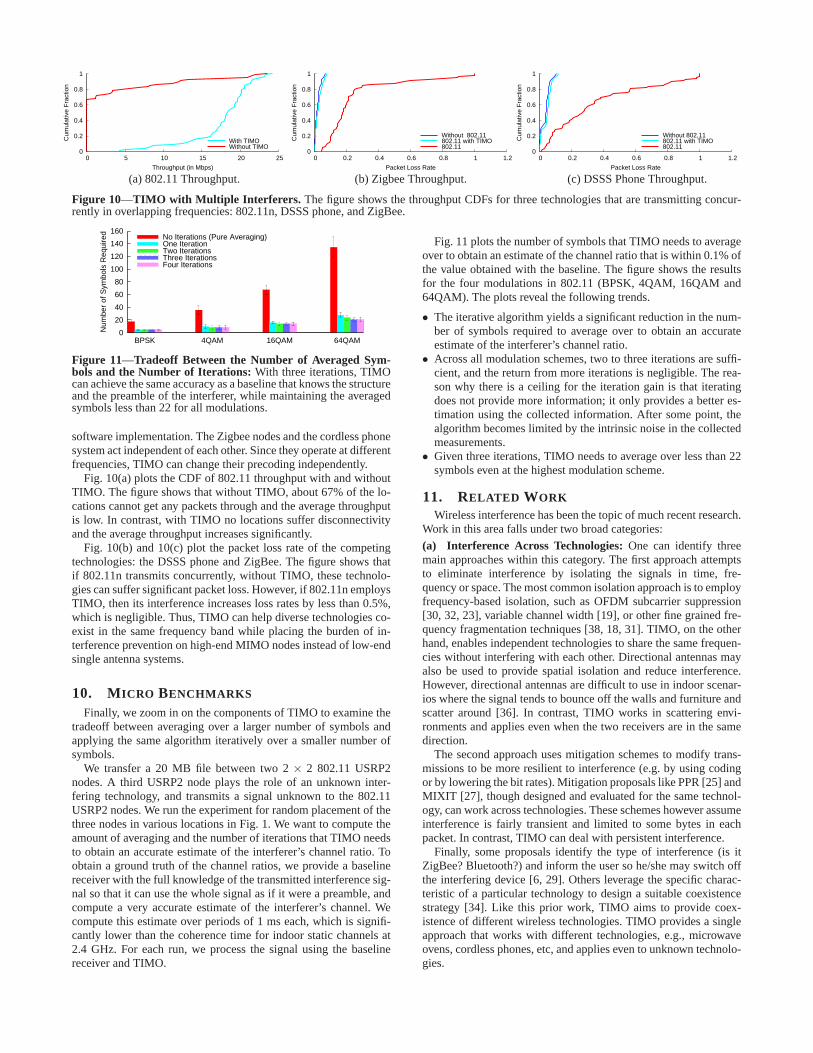
Figure 10—TIMO with Multiple Interferers. The figure shows the throughput CDFs for three technologies that are transmitting concur-rently in overlapping frequencies: 802.11n, DSSS phone, and ZigBee.
0
20
40
60
80
100
120
140
160
BPSK 4QAM 16QAM 64QAM
Num
ber
of S
ymbo
ls R
equi
red No Iterations (Pure Averaging)
One IterationTwo IterationsThree IterationsFour Iterations
Figure 11—Tradeoff Between the Number of Averaged Sym-bols and the Number of Iterations: With three iterations, TIMOcan achieve the same accuracy as a baseline that knows the structureand the preamble of the interferer, while maintaining the averagedsymbols less than 22 for all modulations.
software implementation. The Zigbee nodes and the cordless phonesystem act independent of each other. Since they operate at differentfrequencies, TIMO can change their precoding independently.
Fig. 10(a) plots the CDF of 802.11 throughput with and withoutTIMO. The figure shows that without TIMO, about 67% of the lo-cations cannot get any packets through and the average throughputis low. In contrast, with TIMO no locations suffer disconnectivityand the average throughput increases significantly.
Fig. 10(b) and 10(c) plot the packet loss rate of the competingtechnologies: the DSSS phone and ZigBee. The figure shows thatif 802.11n transmits concurrently, without TIMO, these technolo-gies can suffer significant packet loss. However, if 802.11n employsTIMO, then its interference increases loss rates by less than 0.5%,which is negligible. Thus, TIMO can help diverse technologies co-exist in the same frequency band while placing the burden of in-terference prevention on high-end MIMO nodes instead of low-endsingle antenna systems.
10. MICRO BENCHMARKS
Finally, we zoom in on the components of TIMO to examine thetradeoff between averaging over a larger number of symbols andapplying the same algorithm iteratively over a smaller number ofsymbols.
We transfer a 20 MB file between two 2× 2 802.11 USRP2nodes. A third USRP2 node plays the role of an unknown inter-fering technology, and transmits a signal unknown to the 802.11USRP2 nodes. We run the experiment for random placement of thethree nodes in various locations in Fig. 1. We want to compute theamount of averaging and the number of iterations that TIMO needsto obtain an accurate estimate of the interferer’s channel ratio. Toobtain a ground truth of the channel ratios, we provide a baselinereceiver with the full knowledge of the transmitted interference sig-nal so that it can use the whole signal as if it were a preamble, andcompute a very accurate estimate of the interferer’s channel. Wecompute this estimate over periods of 1 ms each, which is signifi-cantly lower than the coherence time for indoor static channels at2.4 GHz. For each run, we process the signal using the baselinereceiver and TIMO.
Fig. 11 plots the number of symbols that TIMO needs to averageover to obtain an estimate of the channel ratio that is within 0.1% ofthe value obtained with the baseline. The figure shows the resultsfor the four modulations in 802.11 (BPSK, 4QAM, 16QAM and64QAM). The plots reveal the following trends.
• The iterative algorithm yields a significant reduction in the num-ber of symbols required to average over to obtain an accurateestimate of the interferer’s channel ratio.
• Across all modulation schemes, two to three iterations are suffi-cient, and the return from more iterations is negligible. The rea-son why there is a ceiling for the iteration gain is that iteratingdoes not provide more information; it only provides a better es-timation using the collected information. After some point, thealgorithm becomes limited by the intrinsic noise in the collectedmeasurements.
• Given three iterations, TIMO needs to average over less than 22symbols even at the highest modulation scheme.
11. RELATED WORK
Wireless interference has been the topic of much recent research.Work in this area falls under two broad categories:
(a) Interference Across Technologies: One can identify threemain approaches within this category. The first approach attemptsto eliminate interference by isolating the signals in time, fre-quency or space. The most common isolation approach is to employfrequency-based isolation, such as OFDM subcarrier suppression[30, 32, 23], variable channel width [19], or other fine grained fre-quency fragmentation techniques [38, 18, 31]. TIMO, on the otherhand, enables independent technologies to share the same frequen-cies without interfering with each other. Directional antennas mayalso be used to provide spatial isolation and reduce interference.However, directional antennas are difficult to use in indoor scenar-ios where the signal tends to bounce off the walls and furniture andscatter around [36]. In contrast, TIMO works in scattering envi-ronments and applies even when the two receivers are in the samedirection.
The second approach uses mitigation schemes to modify trans-missions to be more resilient to interference (e.g. by using codingor by lowering the bit rates). Mitigation proposals like PPR [25] andMIXIT [27], though designed and evaluated for the same technol-ogy, can work across technologies. These schemes however assumeinterference is fairly transient and limited to some bytes in eachpacket. In contrast, TIMO can deal with persistent interference.
Finally, some proposals identify the type of interference (is itZigBee? Bluetooth?) and inform the user so he/she may switch offthe interfering device [6, 29]. Others leverage the specific charac-teristic of a particular technology to design a suitable coexistencestrategy [34]. Like this prior work, TIMO aims to provide coex-istence of different wireless technologies. TIMO provides a singleapproach that works with different technologies, e.g., microwaveovens, cordless phones, etc, and applies even to unknown technolo-gies.
(b) Interference from the Same Technology: Recent work inthis category include interference cancellation [22], ZigZag [20]and analog network coding [26] which address the problem of in-terference from other 802.11 nodes. The closest to ours is priorwork on MIMO systems which enables multiple transmitters totransmit concurrently without interference. This includes schemeslike SAM [35], Interference Alignment and Cancellation [21], andbeamforming systems [16]. Unlike these schemes, however, TIMOdelivers a MIMO system that enables cooperation with multiple dif-ferent wireless technologies.
Finally, TIMO is related to prior work on interference man-agement in cellular networks that uses multiple antennas to miti-gate interference from cellular nodes operating in adjacent cellu-lar cells [36, 4]. However, in contrast to this work that addressesinter-cell interference from the same technology, TIMO developsalgorithms and techniques to address interference across differenttechnologies.
12. CONCLUSION
This paper presents TIMO, a MIMO design that enables 802.11nto communicate in the presence of high-power cross-technology in-terference. TIMO exploits 802.11n’s MIMO capability to treat ahigh-power signal from a different technology as if it were anotherstream from the same technology, hence enabling diverse technolo-gies to share the same frequency band. We show via a proof-of-concept implementation that TIMO enables 802.11n to communi-cate effectively in the presence of typical 802.11n interferers. Be-yond 802.11n, we believe that TIMO provides the first step for anew form of coexistence, in which different technologies do notnecessarily have to find unoccupied bands and could, in crowdedenvironments, occupy the same band, thus increasing spectral effi-ciency.
Acknowledgments: We thank Nabeel Ahmed, Arthur Berger, NateKushman, Kate Lin, Hariharan Rahul, and Lili Qiu for their insightful com-ments. This research is supported by NSF Grant No. CNS-0721857 andXXX.
13. REFERENCES[1] 20 Myths of Wi-Fi Interference: Dispel Myths to Gain
High-Performing and Reliable Wireless, White paperC11-44927.1-00, Cisco, December 2007.
[2] 2.4GHz 4-Channel Wireless Receiver and 4 Wireless Infrared ColorCameras, Genica. www.genica.com.
[3] AirMaestro Spectrum Analysis Solution, Bandspeed.www.bandspeed.com.
[4] ArrayComm. www.arraycomm.com.[5] Bluetooth Basics, Bluetooth SIG Inc., 2011. www.bluetooth.com.[6] Cisco CleanAir Technology, Cisco.
www.cisco.com/en/US/netsol/ns1070/index.html.[7] Estimating the Utilisation of Key License-Exempt Spectrum Bands,
Final Report REP003, Mass Consultants Ltd., Ofcom, April 2009.[8] Evaluating Interference in Wireless LANs: Recommended Practice,
White paper FPG 2010-135.1, Farpoint Group Technical Note, April2010.
[9] Fury GPS Disciplined Oscillator, Jackson Labs.www.jackson-labs.com.
[10] Miercom: Cisco CleanAir Competitive Testing, Lab Test RerpotDR100409D, Miercom, April 2010.
[11] Motorola Airdefense Solutions, Motorola. www.airdefense.net.[12] Uniden TRU4465: Dual Handset Powermax 2.4GHz Cordless
Systems, Uniden. www.uniden.com.[13] Universal Software Radio Peripheral, Ettus Inc. www.ettus.com.[14] Wireless RF Interference Customer Survey Result, White paper
C11-609300-00, Cisco, 2010.[15] Local and metropolitan area networks–specific requirements part 11:
Wireless LAN medium access control (MAC) and physical layer(PHY) specifications.IEEE Std 802.11, October 2009.
[16] E. Aryafar, N. Anand, T. Salonidis, and E. W. Knightly. Design andExperimental Evaluation of Multi-user Beamforming in WirelessLANs. In Proc. ACM MobiCom 2010, pages 197–208, Chicago, IL,2010.
[17] Bandspeed. Understanding the Effects of Radio Frequency (RF)Interference on WLAN performance and Security, 2010.
[18] L. Cao, L. Yang, and H. Zheng. The Impact of Frequency-Agility onDynamic Spectrum Sharing. InProc. IEEE DySPAN 2010, pages 1–12, Singapore, 2010.
[19] R. Chandra, R. Mahajan, T. Moscibroda, R. Raghavendra,andP. Bahl. A Case for Adapting Channel Width in Wireless Networks.In Proc. ACM SIGCOMM 2008, pages 135–146, Seattle, WA, 2008.
[20] S. Gollakota and D. Katabi. Zigzag Decoding: Combating HiddenTerminals in Wireless Networks. InProc. ACM SIGCOMM 2008,pages 159–170, Seattle, WA, 2008.
[21] S. Gollakota, S. D. Perli, and D. Katabi. Interference Alignment andCancellation. InProc. ACM SIGCOMM 2009, pages 159–170,Barcelona, Spain, 2009.
[22] D. Halperin, J. Ammer, T. Anderson, and D. Wetherall. InterferenceCancellation: Better Receivers for a New Wireless MAC. InProc.ACM HotNets 2007, Atlanta, GA, 2007.
[23] Y. He, J. Fang, J. Zhang, H. Shen, K. Tan, and Y. Zhang. MPAP:Virtualization Architecture for Heterogenous Wireless APs. InProc.ACM SIGCOMM 2010, pages 475–476, New Delhi, India, 2010.
[24] J. Heiskala and J. Terry.OFDM Wireless LANs: A Theoretical andPractical Guide. Sams Publishing, 2001.
[25] K. Jamieson and H. Balakrishnan. PPR: Partial Packet Recovery forWireless Networks. InProc. ACM SIGCOMM 2007, pages 409–420,Kyoto, Japan, 2007.
[26] S. Katti, S. Gollakota, and D. Katabi. Embracing WirelessInterference: Analog Network Coding. InProc. ACM SIGCOMM2007, pages 397–408, Kyoto, Japan, 2007.
[27] S. Katti, D. Katabi, H. Balakrishnan, and M. Medard. Symbol-LevelNetwork Coding for Wireless Mesh Networks. InProc. ACMSIGCOMM 2008, pages 401–412, Seattle, WA, 2008.
[28] J. Ketchum, S. Nanda, R. Walton, S. Howard, M. Wallace, B.Bjerke,I. Medvedev, S. Abraham, A. Meylan, and S. Surineni. SystemDescription and Operating Principles for High ThroughputEnhancements to 802.11, QUALCOMM Inc., April 2005.
[29] K. Lakshminarayanan, S. Sapra, S. Seshan, and P. Steenkiste.RFDump: An Architecture for Monitoring the Wireless Ether. InProc. CoNEXT 2009, pages 253–264, Rome, Italy, 2009.
[30] S. Mishra, R. Brodersen, S. Brink, and R. Mahadevappa. Detect andAvoid: An Ultra-Wideband/WiMAX Coexistence Mechanism.IEEECommunications Magazine, 45(6):68 –75, June 2007.
[31] T. Moscibroda, R. Chandra, Y. Wu, S. Sengupta, P. Bahl, andY. Yuan. Load-Aware Spectrum Distribution in Wireless LANs. InProc. IEEE ICNP 2008, pages 137 –146, Orlando, FL, 2008.
[32] H. Rahul, N. Kushman, D. Katabi, C. Sodini, and F. Edalat.Learningto Share: Narrowband-Friendly Wideband Networks. InProc. ACMSIGCOMM 2008, pages 147–158, Seattle, WA, 2008.
[33] SourceForge. iperf.sourceforge.net.[34] T. Taher, M. Misurac, J. LoCicero, and D. Ucci. Microwave Oven
Signal Modelling. InProc. IEEE WCNC 2008, pages 1235 –1238,Las Vegas, NV, 2008.
[35] K. Tan, H. Liu, J. Fang, W. Wang, J. Zhang, M. Chen, and G. M.Voelker. SAM: Enabling Practical Spatial Multiple Access inWireless LAN. InProc. ACM MobiCom 2009, pages 49–60, Beijing,China, 2009.
[36] D. Tse and P. Vishwanath.Fundamentals of WirelessCommunications. Cambridge University Press, May 2005.
[37] M. Vutukuru, H. Balakrishnan, and K. Jamieson. Cross-LayerWireless Bit Rate Adaptation. InProc. ACM SIGCOMM 2009, pages3–14, Barcelona, Spain, 2009.
[38] L. Yang, W. Hou, L. Cao, B. Y. Zhao, and H. Zheng. SupportingDemanding Wireless Applications with Frequency-Agile Radios. InProc. USENIX NSDI 2010, pages 5–5, San Jose, CA, 2010.
[39] P. Zetterberg. Experimental Investigation of TDD Reciprocity-BasedZero-Forcing Transmit Precoding.EURASIP J. Adv. Signal Process,2011:5:1–5:10, January 2011.
[40] H. Zhao, Y. Q. Shi, and N. Ansari. Hiding Data in MultimediaStreaming over Networks. InProc. CNSR 2010, pages 50 –55,Montreal, QC, 2010.
APPENDIXGeneralization to any number of antennas. Let M be the number of an-tennas at the 802.11 receiver. Say, there areK concurrent 802.11n transmis-sions,s1(t) · · · sK(t) whose channels are known at the receiver. We wouldlike to estimate the interferer’s channel in the presence of theseK transmis-sions. Let,hk
j be the channel coefficient of thekth transmission at thejthantenna on the receiver. Similarly, lethj denote the channel of the interfererto thejth antenna on the receiver.
First, we note that one can always seth1 to one. This can be done byconsidering the interferer to be the scaled value,h1i(t), instead ofi(t). Thus,the received equation on thejth antenna is given by,
y1(t) = i(t) +∑
hk1sk(t)
yj(t) = hji(t) +∑
hkj sk(t),∀j 6= 1
Now, since the channel of the interferer is given by(1,h1, · · · , hM), it issufficient to find thehis. To do this, the receiver correlates all the equationsabove withy1(t)∗ and taking the expectation.
E[y1(t)y1(t)∗] = Pi +
∑hk
1hk∗1 Pk
E[yj(t)y1(t)∗] = hjPi +
∑hk
j hk∗1 Pk,
whereP’s are the corresponding powers. Since the only unknowns in theabove equations arePi andhj’s, they can be easily computed. Thus, even inthe presence ofK concurrent transmissions, a 802.11 receiver can estimatethe channel of the interferer without knowing the preamble.