cleaning and degassing of skim tank at oilsands …
TRANSCRIPT

CASE STUDY
CLEANING AND DEGASSING OF SKIM TANKAT OILSANDS PROCESSING PLANT
ISO 9001:2015

SCOPECleaning and degassing of skim tank at oilsands processing plant using ROC 60 VP and CITRIKLEEN® HD.
The PROBLEMA major western Canadian oil producer had planned a Turnaround for inspection and maintenance of their Skim Tank. The Skim Tank is typically used in SAGD facilities to reduce the dispersed oil content in produced water.After the initial separation of the produced fluids, the produced water still contains finely dispersed solids and oil.Separation in the Skim Tank is based on the difference between the specific gravity of oil and water. When the retention time is sufficient, oil floats to the surface and can be separated by an overflow.
The Skim Tank had dimensions 26 meters (85 ft.) diameter and 8.5 meters (28 ft.) High, with an estimated sludge volume of 950 cubic meters (approximately 1.8 meters or 6 ft. deep).
The operator of the facility desired to optimize the tank cleaning procedure in order to minimize the duration from “oil out`` until the tank could be degassed and made safe for opening, inspection and mechanical work.
.
Figure 1: Skim Tank Typical Arrangement
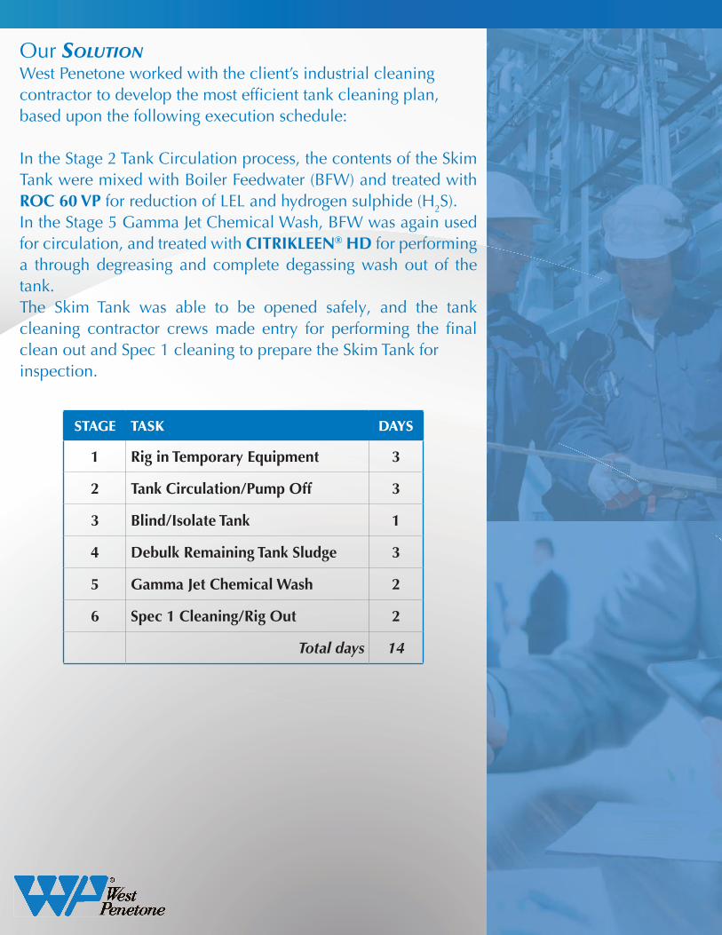
Our SOLUTIONWest Penetone worked with the client’s industrial cleaning contractor to develop the most efficient tank cleaning plan, based upon the following execution schedule:
In the Stage 2 Tank Circulation process, the contents of the Skim Tank were mixed with Boiler Feedwater (BFW) and treated with ROC 60 VP for reduction of LEL and hydrogen sulphide (H2S). In the Stage 5 Gamma Jet Chemical Wash, BFW was again used for circulation, and treated with CITRIKLEEN® HD for performing a through degreasing and complete degassing wash out of the tank.The Skim Tank was able to be opened safely, and the tank cleaning contractor crews made entry for performing the final clean out and Spec 1 cleaning to prepare the Skim Tank forinspection.
STAGE TASK DAYS
1 Rig in Temporary Equipment 3
2 Tank Circulation/Pump Off 3
3 Blind/Isolate Tank 1
4 Debulk Remaining Tank Sludge 3
5 Gamma Jet Chemical Wash 2
6 Spec 1 Cleaning/Rig Out 2
Total days 14

RESULTS ACHIEVED
X ROC 60 VP used in the Stage 2 Tank Circulation process reduced H2S in the produced water from 2,500 ppm to less than 10 ppm, and reduced LEL to 2%, prior to pumping off the contents of the Skim Tank to an adjacent Slop Oil Tank at the facility.
X The Gamma Jet Wash process using CITRIKLEEN® HD decreased the duration required for the overall tank cleaning by reduction of remaining oil and sludge, and providing degassed vapour space with H2S reduced to 0 ppm and LEL to 0%, and minimizing final tank clean out time while using confined space entry crews.
The following images demonstrate the results achieved for the Skim Tank cleaning using West Penetone ROC 60 VP and CITRIKLEEN® HD procedures for this project:.
Figure 2: Skim Tank Internal Arrangement

www.penetone.comwww.westpenetone.com
PENETONE CORPORATION125 Kingsland AvenueClifton, NJ 070141.800.631.1652
PENETONE CORPORATION 8201 4th Street, Unit GDowney, CA 90241 1.800.421.6211
United StatesWEST PENETONE INC.11411-160 Street Edmonton, Alberta T5M 3T71.866.454.3919
WEST PENETONE INC.10,900 Secant StAnjou, Quebec H1J 1S5 1.800.361.8927
Canada
A comprehensive and integrated approachWith over 100 years of product development, manufacturing and application experience, the West Penetonefamily of companies has designed and patented many products to satisfy the needs of our clients world wide.
Our technical group provides customers effective support to ensure that contaminents are paired with the right chemistry for any task.
Establishing and maintaining a collaborative approach with our customers in tackling their operational andmaintenance challenges is key to realizing efficiencies and cost savings.
Questions? [email protected]
Figure 3: Skim Tank Internal Baffle Walls and Floor
Figure 4: Skim Tank Internal Floor
Figure 5: Skim Tank Internal Upper Shell and Roof