class fourth units (second part) - unipamplona · 3 moving boundary work ... specific heat at...
TRANSCRIPT

CLASS
Fourth Units (Second part)

Energy analysis of
closed systems
Copyright © The McGraw-Hill Companies, Inc. Permission required for reproduction or display.
3
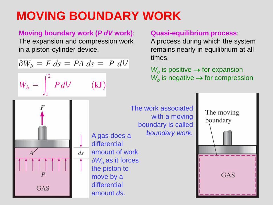
MOVING BOUNDARY WORK
Moving boundary work (P dV work):
The expansion and compression work
in a piston-cylinder device.
The work associated
with a moving
boundary is called
boundary work. A gas does a
differential
amount of work
Wb as it forces
the piston to
move by a
differential
amount ds.
Quasi-equilibrium process:
A process during which the system
remains nearly in equilibrium at all
times.
Wb is positive for expansion
Wb is negative for compression

4
The area under the process
curve on a P-V diagram
represents the boundary work.
The boundary
work done
during a process
depends on the
path followed as
well as the end
states.
The net work done
during a cycle is the
difference between
the work done by
the system and the
work done on the
system.

Boundary work for a constant-volume process
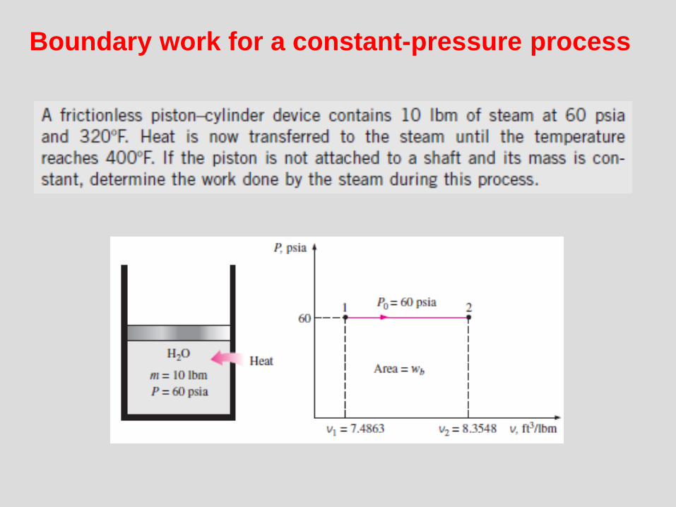
Boundary work for a constant-pressure process

7
Polytropic, Isothermal, and Isobaric processes
Polytropic process: C, n (polytropic exponent) constants
Polytropic
process
Polytropic and for ideal gas
When n = 1
(isothermal process)
Schematic and
P-V diagram for
a polytropic
process.
Constant pressure process
What is the boundary
work for a constant-
volume process?

Boundary work for a constant-pressure process

9
ENERGY BALANCE FOR CLOSED SYSTEMS
Energy balance for any system
undergoing any process
Energy balance
in the rate form
The total quantities are related to the quantities per unit time is
Energy balance per
unit mass basis
Energy balance in
differential form
Energy balance
for a cycle

10
Energy balance when sign convention is used (i.e., heat input and work
output are positive; heat output and work input are negative).
Various forms of the first-law relation
for closed systems when sign
convention is used. For a cycle E = 0, thus Q = W.
The first law cannot be proven mathematically, but no process in nature is known
to have violated the first law, and this should be taken as sufficient proof.

11
Energy balance for a constant-pressure
expansion or compression process
HWU b
For a constant-pressure expansion
or compression process:
An example of constant-pressure process
General analysis for a closed system
undergoing a quasi-equilibrium
constant-pressure process. Q is to the
system and W is from the system.
12
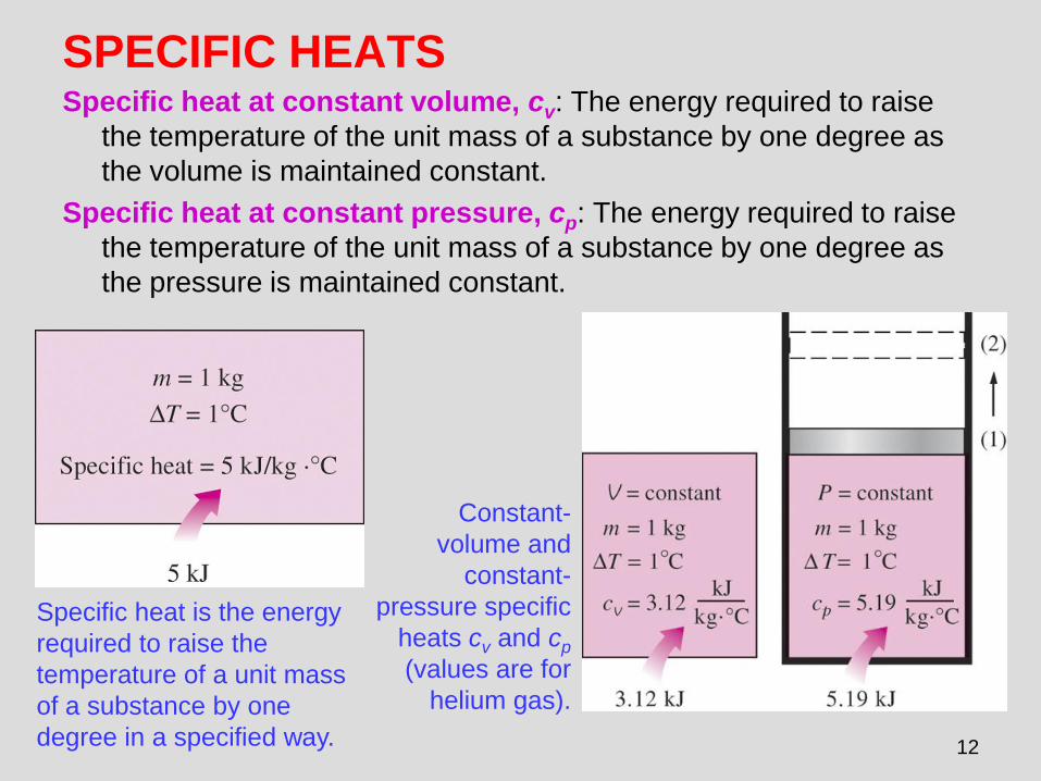
SPECIFIC HEATS Specific heat at constant volume, cv: The energy required to raise
the temperature of the unit mass of a substance by one degree as
the volume is maintained constant.
Specific heat at constant pressure, cp: The energy required to raise
the temperature of the unit mass of a substance by one degree as
the pressure is maintained constant.
Specific heat is the energy
required to raise the
temperature of a unit mass
of a substance by one
degree in a specified way.
Constant-
volume and
constant-
pressure specific
heats cv and cp
(values are for
helium gas).

13
• The equations in the figure are valid for any substance undergoing any process.
• cv and cp are properties.
• cv is related to the changes in internal energy and cp to the changes in enthalpy.
• A common unit for specific heats is kJ/kg · °C or kJ/kg · K. Are these units identical?
The specific heat of a substance
changes with temperature.
True or False?
cp is always greater than cv.
Formal definitions of cv and cp.

14
INTERNAL ENERGY, ENTHALPY,
AND SPECIFIC HEATS OF IDEAL GASES
Joule showed
using this
experimental
apparatus that
u=u(T)
For ideal gases,
u, h, cv, and cp
vary with
temperature only.
Internal energy and
enthalpy change of
an ideal gas

15
Ideal-gas
constant-
pressure
specific heats
for some
gases (see
Table A–2c
for cp
equations).
• At low pressures, all real gases approach
ideal-gas behavior, and therefore their
specific heats depend on temperature only.
• The specific heats of real gases at low
pressures are called ideal-gas specific
heats, or zero-pressure specific heats, and
are often denoted cp0 and cv0.
• u and h data for a number of
gases have been tabulated.
• These tables are obtained by
choosing an arbitrary reference
point and performing the
integrations by treating state 1
as the reference state.
In the preparation of ideal-gas
tables, 0 K is chosen as the
reference temperature.

16
(kJ/kg)
For small temperature intervals, the
specific heats may be assumed to vary
linearly with temperature.
Internal energy and enthalpy change when
specific heat is taken constant at an
average value
The relation u = cv T
is valid for any kind of
process, constant-
volume or not.

17
1. By using the tabulated u and h data. This is the easiest and most accurate way when tables are readily available.
2. By using the cv or cp relations (Table A-2c) as a function of temperature and performing the integrations. This is very inconvenient for hand calculations but quite desirable for computerized calculations. The results obtained are very accurate.
3. By using average specific heats. This is very simple and certainly very convenient when property tables are not available. The results obtained are reasonably accurate if the temperature interval is not very large.
Three ways of calculating u and h
Three ways of calculating u.

18
Specific Heat Relations of Ideal Gases
The cp of an ideal gas can be
determined from a knowledge of
cv and R.
On a molar basis
The relationship between cp, cv and R
Specific
heat ratio
• The specific ratio varies with
temperature, but this variation is
very mild.
• For monatomic gases (helium,
argon, etc.), its value is essentially
constant at 1.667.
• Many diatomic gases, including air,
have a specific heat ratio of about
1.4 at room temperature.
dh = cpdT and du = cvdT

19
INTERNAL ENERGY, ENTHALPY, AND
SPECIFIC HEATS OF SOLIDS AND LIQUIDS
The specific volumes of
incompressible substances
remain constant during a
process.
The cv and cp values of
incompressible substances are
identical and are denoted by c.
Incompressible substance: A substance whose specific volume
(or density) is constant. Solids and liquids are incompressible
substances.

20
Internal Energy Changes
Enthalpy Changes
The enthalpy of a
compressed liquid A more accurate relation than

Energy analysis of
open systems
Copyright © The McGraw-Hill Companies, Inc. Permission required for reproduction or display.

22
FLOW WORK AND THE
ENERGY OF A FLOWING FLUID
Schematic for flow work.
Flow work, or flow energy: The work (or energy)
required to push the mass into or out of the control
volume. This work is necessary for maintaining a
continuous flow through a control volume.
In the absence of acceleration, the force
applied on a fluid by a piston is equal to the
force applied on the piston by the fluid.

23
Total Energy of a Flowing Fluid
The total energy consists of three parts for a nonflowing fluid and four parts for a
flowing fluid.
h = u + Pv
The flow energy is
automatically taken
care of by enthalpy.
In fact, this is the
main reason for
defining the
property enthalpy.

24
Energy Transport by Mass
The product is the energy
transported into control volume by
mass per unit time.
iim
When the kinetic and potential energies
of a fluid stream are negligible
When the properties of the mass at
each inlet or exit change with time
as well as over the cross section

ENERGY ANALYSIS OF STEADY-FLOW
SYSTEMS
• For steady flow, time rate of change of the energy content of the CV is zero.
• This equation states: the net rate of energy transfer to a CV by heat and work transfers during steady flow is equal to the difference between the rates of outgoing and incoming energy flows with mass.
2 2
, , ,2 2
net in shaft net in
out in
V VQ W m h gz m h gz

26
ENERGY ANALYSIS OF STEADY-FLOW
SYSTEMS
Many engineering systems such
as power plants operate under
steady conditions.
Under steady-flow conditions, the mass
and energy contents of a control volume
remain constant.
Under steady-flow conditions,
the fluid properties at an inlet
or exit remain constant (do not
change with time).
27
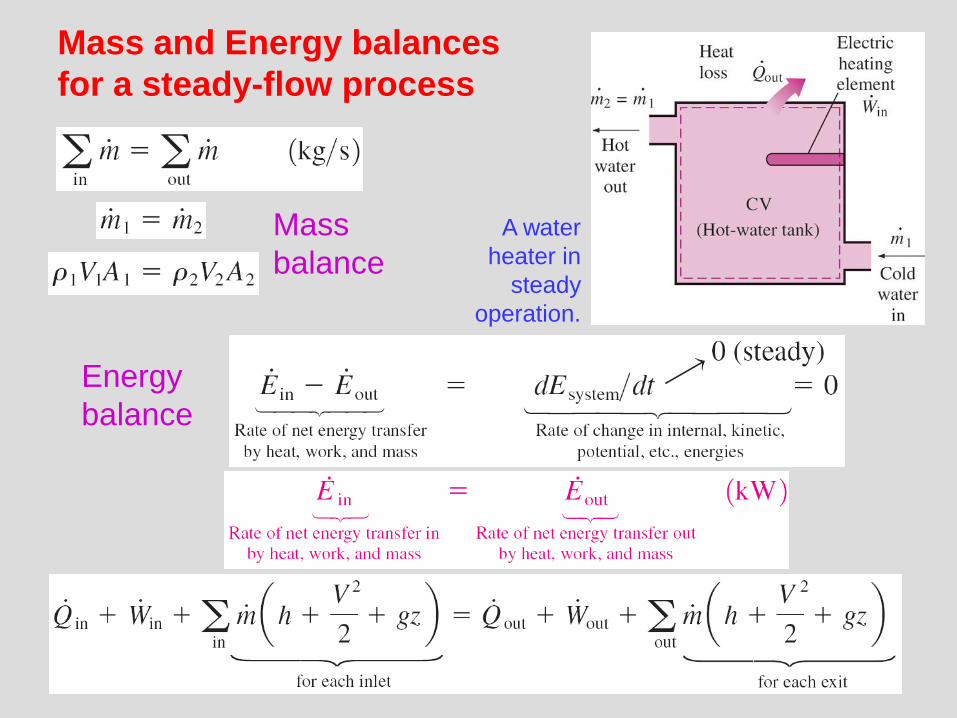
Mass and Energy balances
for a steady-flow process
A water
heater in
steady
operation.
Mass
balance
Energy
balance

28
Under steady operation,
shaft work and electrical
work are the only forms of
work a simple compressible
system may involve.
Energy balance relations with sign conventions
(i.e., heat input and work output are positive)
when kinetic and potential energy
changes are negligible
Some energy unit equivalents

29
SOME STEADY-FLOW ENGINEERING DEVICES
A modern land-based gas turbine used for electric power
production. This is a General Electric LM5000 turbine. It
has a length of 6.2 m, it weighs 12.5 tons, and produces
55.2 MW at 3600 rpm with steam injection.
Many engineering devices operate essentially under the same conditions
for long periods of time. The components of a steam power plant (turbines,
compressors, heat exchangers, and pumps), for example, operate nonstop for
months before the system is shut down for maintenance. Therefore, these
devices can be conveniently analyzed as steady-flow devices.
At very high velocities,
even small changes in
velocities can cause
significant changes in
the kinetic energy of the
fluid.
30
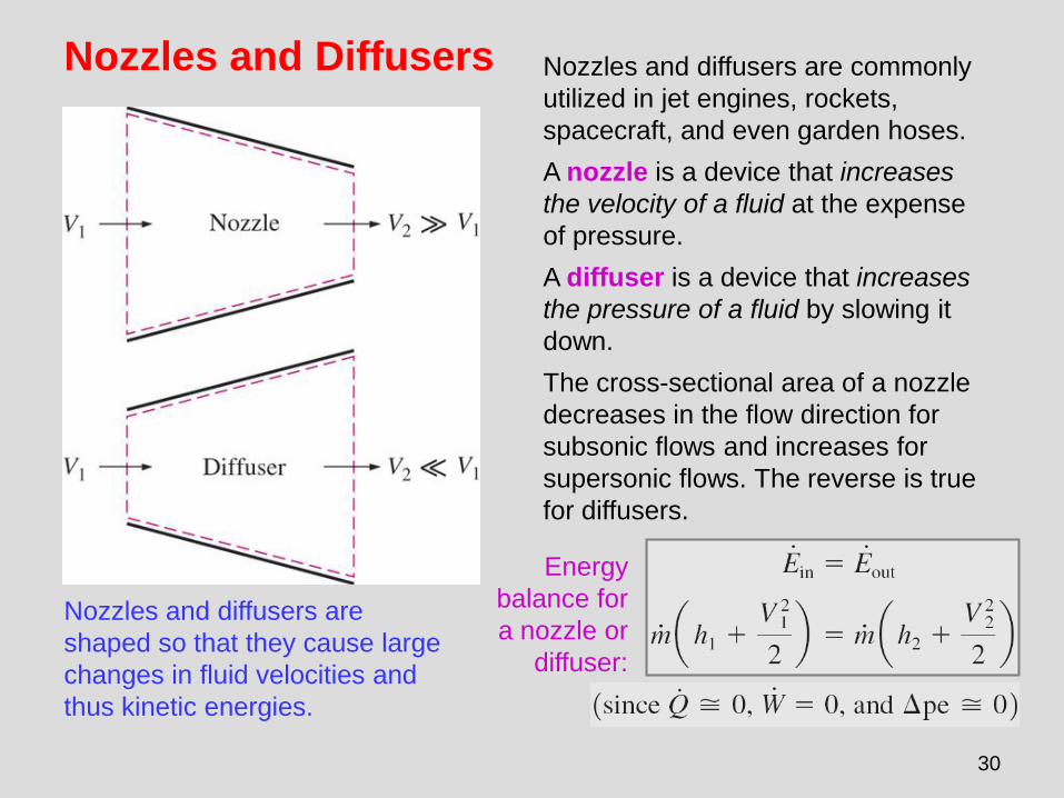
Nozzles and Diffusers
Nozzles and diffusers are
shaped so that they cause large
changes in fluid velocities and
thus kinetic energies.
Nozzles and diffusers are commonly
utilized in jet engines, rockets,
spacecraft, and even garden hoses.
A nozzle is a device that increases
the velocity of a fluid at the expense
of pressure.
A diffuser is a device that increases
the pressure of a fluid by slowing it
down.
The cross-sectional area of a nozzle
decreases in the flow direction for
subsonic flows and increases for
supersonic flows. The reverse is true
for diffusers.
Energy
balance for
a nozzle or
diffuser:

31
Turbines and
Compressors • Turbine drives the electric generator In
steam, gas, or hydroelectric power plants.
• As the fluid passes through the turbine,
work is done against the blades, which
are attached to the shaft. As a result, the
shaft rotates, and the turbine produces
work.
• Compressors, as well as pumps and
fans, are devices used to increase the
pressure of a fluid. Work is supplied to
these devices from an external source
through a rotating shaft.
• A fan increases the pressure of a gas
slightly and is mainly used to mobilize a
gas.
• A compressor is capable of compressing
the gas to very high pressures.
• Pumps work very much like compressors
except that they handle liquids instead of
gases.
Energy balance for the
compressor in this figure:

32
Throttling valves Throttling valves are any kind of flow-restricting devices
that cause a significant pressure drop in the fluid.
What is the difference between a turbine and a
throttling valve?
The pressure drop in the fluid is often accompanied by a
large drop in temperature, and for that reason throttling
devices are commonly used in refrigeration and air-
conditioning applications.
The temperature of an ideal gas does
not change during a throttling
(h = constant) process since h = h(T).
During a throttling process, the enthalpy
of a fluid remains constant. But internal
and flow energies may be converted to
each other.
Energy
balance
33
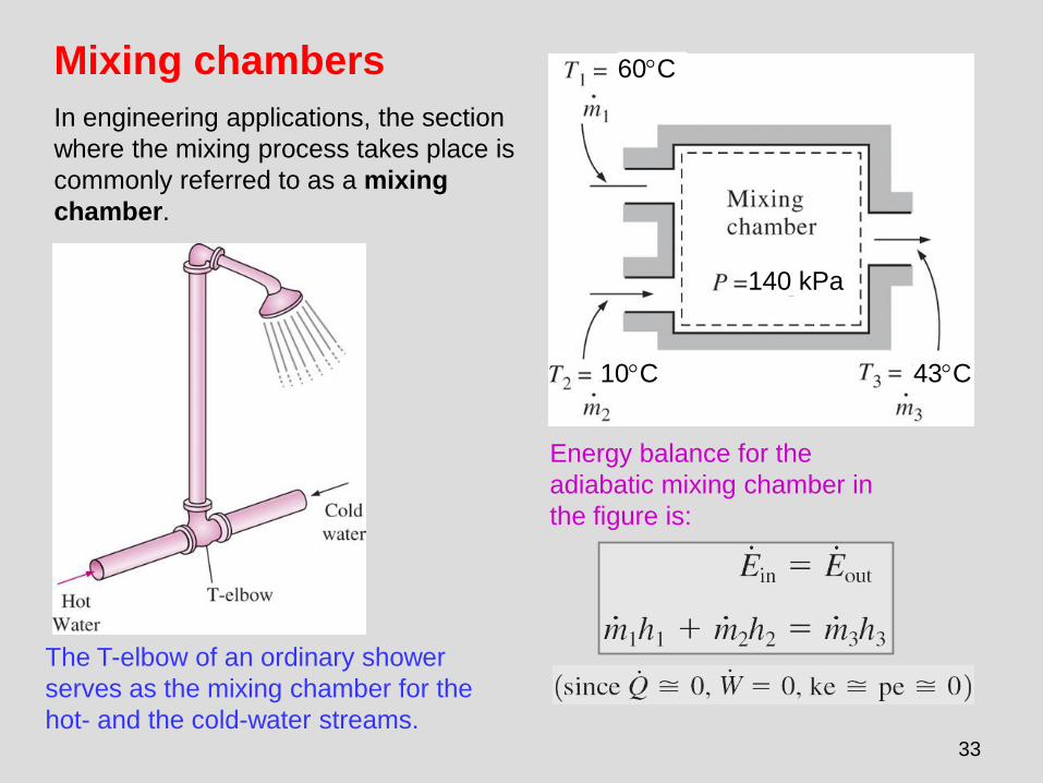
Mixing chambers
In engineering applications, the section
where the mixing process takes place is
commonly referred to as a mixing
chamber.
The T-elbow of an ordinary shower
serves as the mixing chamber for the
hot- and the cold-water streams.
Energy balance for the
adiabatic mixing chamber in
the figure is:
10C
60C
43C
140 kPa

34
Heat exchangers
Heat exchangers are
devices where two moving
fluid streams exchange heat
without mixing. Heat
exchangers are widely used
in various industries, and
they come in various
designs.
A heat exchanger
can be as simple as
two concentric pipes.
Mass and energy
balances for the adiabatic
heat exchanger in the
figure is:
The heat transfer associated with a heat
exchanger may be zero or nonzero depending on
how the control volume is selected.

35
Pipe and duct fow
The transport of liquids or gases in
pipes and ducts is of great importance
in many engineering applications. Flow
through a pipe or a duct usually satisfies
the steady-flow conditions.
Heat losses from
a hot fluid
flowing through
an uninsulated
pipe or duct to
the cooler
environment
may be very
significant.
Pipe or duct flow may involve more than
one form of work at the same time.
Energy balance
for the pipe flow
shown in the
figure is
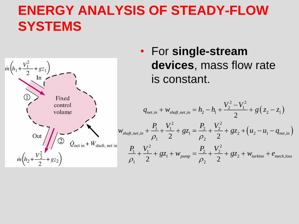
ENERGY ANALYSIS OF STEADY-FLOW
SYSTEMS
• For single-stream
devices, mass flow rate
is constant.
2 2
2 1, , , 2 1 2 1
2 2
1 1 2 2, , 1 2 2 1 ,
1 2
2 2
1 1 2 21 2 ,
1 2
2
2 2
2 2
net in shaft net in
shaft net in net in
pump turbine mech loss
V Vq w h h g z z
P V P Vw gz gz u u q
P V P Vgz w gz w e
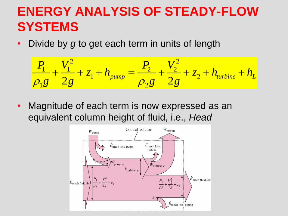
ENERGY ANALYSIS OF STEADY-FLOW
SYSTEMS
• Divide by g to get each term in units of length
• Magnitude of each term is now expressed as an
equivalent column height of fluid, i.e., Head
2 2
1 1 2 21 2
1 22 2pump turbine L
P V P Vz h z h h
g g g g

The Bernoulli Equation
• If we neglect piping losses, and have a system without pumps or turbines
• This is the Bernoulli equation
• It can also be derived using Newton's second law of motion (see text, p. 187).
• 3 terms correspond to: Static, dynamic, and hydrostatic head (or pressure).
2 2
1 1 2 21 2
1 22 2
P V P Vz z
g g g g

HGL and EGL
• It is often convenient
to plot mechanical
energy graphically
using heights.
• Hydraulic Grade Line
• Energy Grade Line
(or total energy)
PHGL z
g
2
2
P VEGL z
g g

The Bernoulli Equation
• The Bernoulli equation
is an approximate relation
between pressure,
velocity, and elevation
and is valid in regions of
steady, incompressible
flow where net frictional
forces are negligible.
• Equation is useful in flow
regions outside of
boundary layers and
wakes.
The Bernoulli Equation
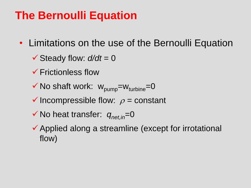
• Limitations on the use of the Bernoulli Equation
Steady flow: d/dt = 0
Frictionless flow
No shaft work: wpump=wturbine=0
Incompressible flow: = constant
No heat transfer: qnet,in=0
Applied along a streamline (except for irrotational
flow)
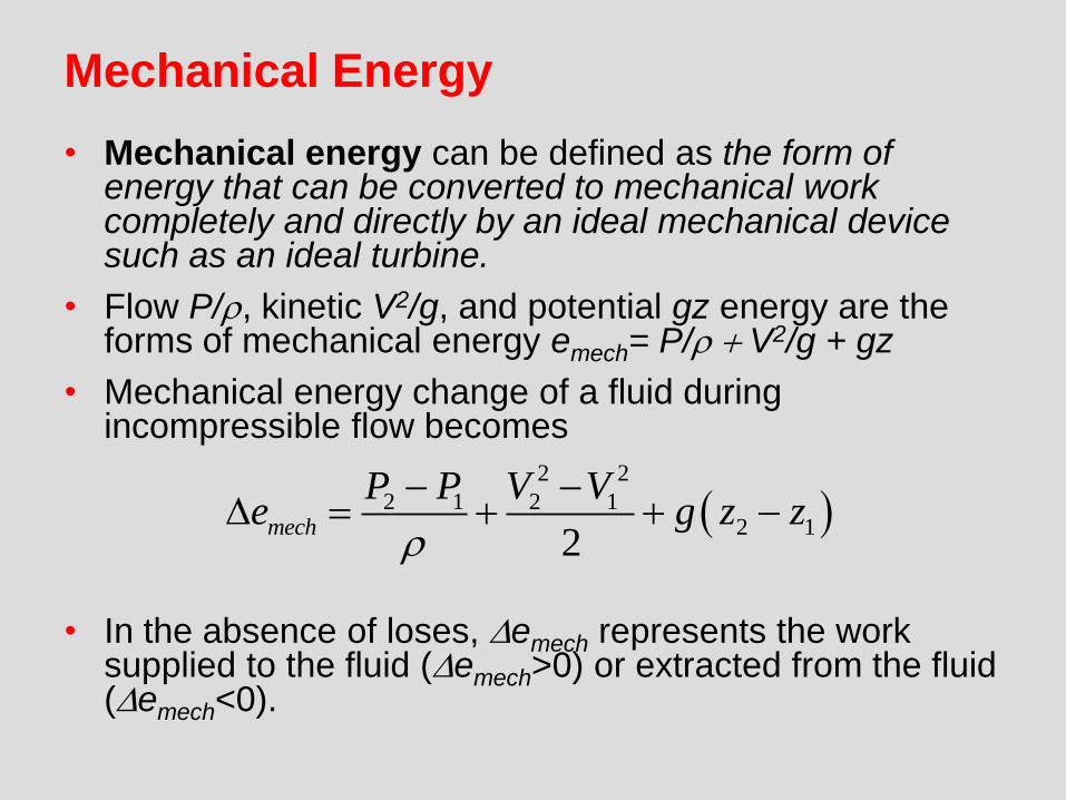
Mechanical Energy
• Mechanical energy can be defined as the form of energy that can be converted to mechanical work completely and directly by an ideal mechanical device such as an ideal turbine.
• Flow P/, kinetic V2/g, and potential gz energy are the forms of mechanical energy emech= P/ V2/g + gz
• Mechanical energy change of a fluid during incompressible flow becomes
• In the absence of loses, emech represents the work supplied to the fluid (emech>0) or extracted from the fluid (emech<0).
2 2
2 1 2 12 1
2mech
P P V Ve g z z
Copyright © The McGraw-Hill Companies, Inc. Permission required for reproduction or display.
3-6
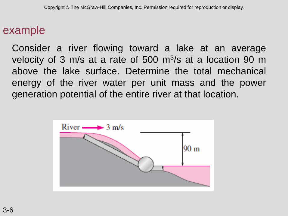
example
Consider a river flowing toward a lake at an average
velocity of 3 m/s at a rate of 500 m3/s at a location 90 m
above the lake surface. Determine the total mechanical
energy of the river water per unit mass and the power
generation potential of the entire river at that location.
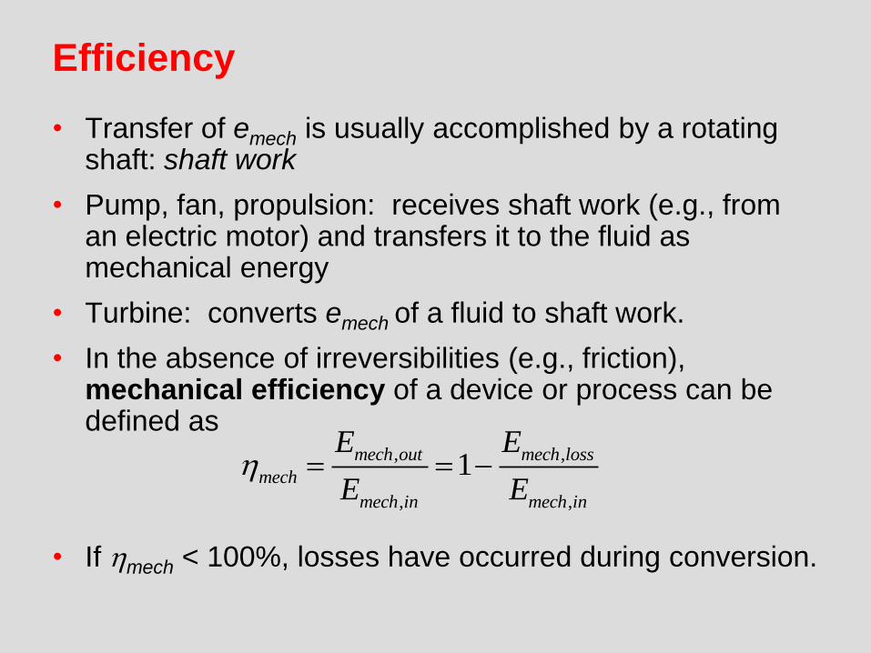
Efficiency
• Transfer of emech is usually accomplished by a rotating shaft: shaft work
• Pump, fan, propulsion: receives shaft work (e.g., from an electric motor) and transfers it to the fluid as mechanical energy
• Turbine: converts emech of a fluid to shaft work.
• In the absence of irreversibilities (e.g., friction), mechanical efficiency of a device or process can be defined as
• If hmech < 100%, losses have occurred during conversion.
, ,
, ,
1mech out mech loss
mech
mech in mech in
E E
E Eh
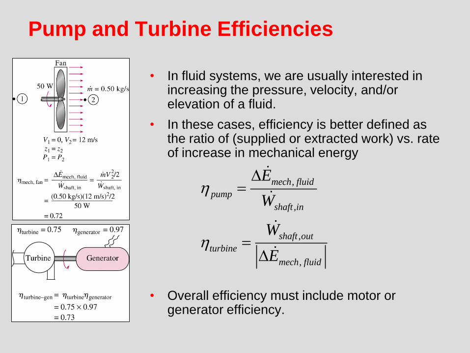
Pump and Turbine Efficiencies
• In fluid systems, we are usually interested in increasing the pressure, velocity, and/or elevation of a fluid.
• In these cases, efficiency is better defined as the ratio of (supplied or extracted work) vs. rate of increase in mechanical energy
• Overall efficiency must include motor or generator efficiency.
,
,
,
,
mech fluid
pump
shaft in
shaft out
turbine
mech fluid
E
W
W
E
h
h
Copyright © The McGraw-Hill Companies, Inc. Permission required for reproduction or display.
3-6
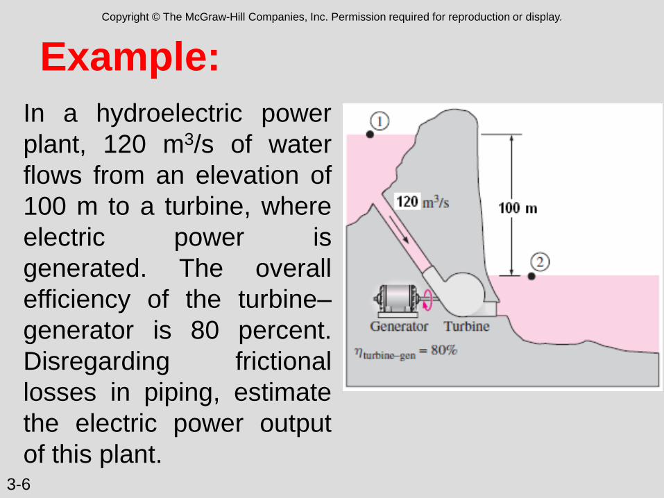
In a hydroelectric power
plant, 120 m3/s of water
flows from an elevation of
100 m to a turbine, where
electric power is
generated. The overall
efficiency of the turbine–
generator is 80 percent.
Disregarding frictional
losses in piping, estimate
the electric power output
of this plant.
Example:
Example:
A garden hose attached with a nozzle is used to fill a 20-gal
bucket. The inner diameter of the hose is 1 in and it reduces
to 0.5 in at the nozzle exit. If the average velocity in the hose
is 8 ft/s, determine:
(a) the volume and mass flow rates of water through the
hose
(b) how long it will take to fill the bucket with water, and
(c) the average velocity of water at the nozzle exit.

Example:

Example: Water flows through a horizontal pipe at a rate of 1 gal/s. The
pipe consist of two sections of diameters 4 in and 2 in with a
smooth reducing section. The pressure difference between the
two pipe sections is measured by a mercury manometer.
Neglecting frictional effects, determine the differential height of
mercury between the two pipe sections.

Example: The liquid in the Figure has a s = 0,85. Estimate the flow rate
from the tank for a) no losses and b) pipe losses
hL = 4.5 V 2/(2g).
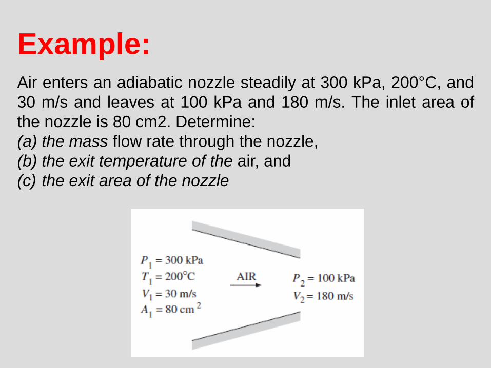
Example: Air enters an adiabatic nozzle steadily at 300 kPa, 200°C, and
30 m/s and leaves at 100 kPa and 180 m/s. The inlet area of
the nozzle is 80 cm2. Determine:
(a) the mass flow rate through the nozzle,
(b) the exit temperature of the air, and
(c) the exit area of the nozzle
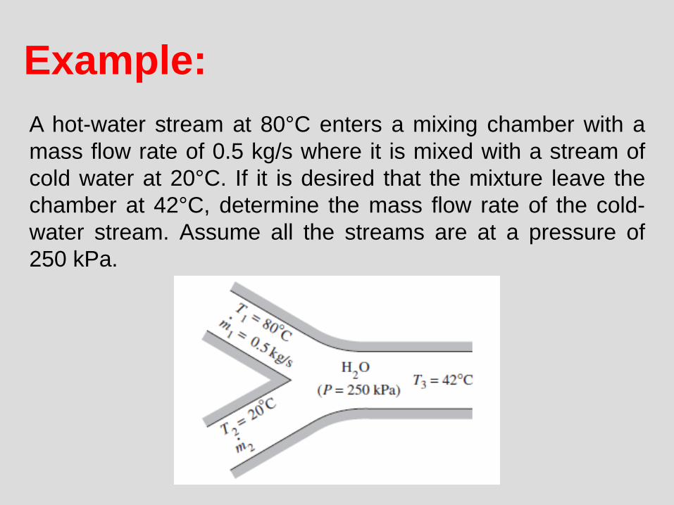
Example:
A hot-water stream at 80°C enters a mixing chamber with a
mass flow rate of 0.5 kg/s where it is mixed with a stream of
cold water at 20°C. If it is desired that the mixture leave the
chamber at 42°C, determine the mass flow rate of the cold-
water stream. Assume all the streams are at a pressure of
250 kPa.

Example:
An oil pump is drawing 35 kW of electric power while
pumping oil with ρ=860 kg/m3 at a rate of 0.15m3/s. The inlet
and outlet diameters of the pipe are 8 cm and 12 cm,
respectively. If the pressure rise of oil in the pump is
measured to be 450kPa and the motor efficiency is 80%,
determine the mechanical efficiency of the pump.

MOMENTUM ANALYSIS

55
NEWTON’S LAWS Newton’s laws: Relations between motions of bodies and the forces
acting on them.
Newton’s first law: A body at rest remains at rest, and a body in
motion remains in motion at the same velocity in a straight path when
the net force acting on it is zero.
Therefore, a body tends to preserve its state of inertia.
Newton’s second law: The acceleration of a body is proportional to
the net force acting on it and is inversely proportional to its mass.
Newton’s third law: When a body exerts a force on a second body,
the second body exerts an equal and opposite force on the first.
Therefore, the direction of an exposed reaction force depends on the
body taken as the system.
56
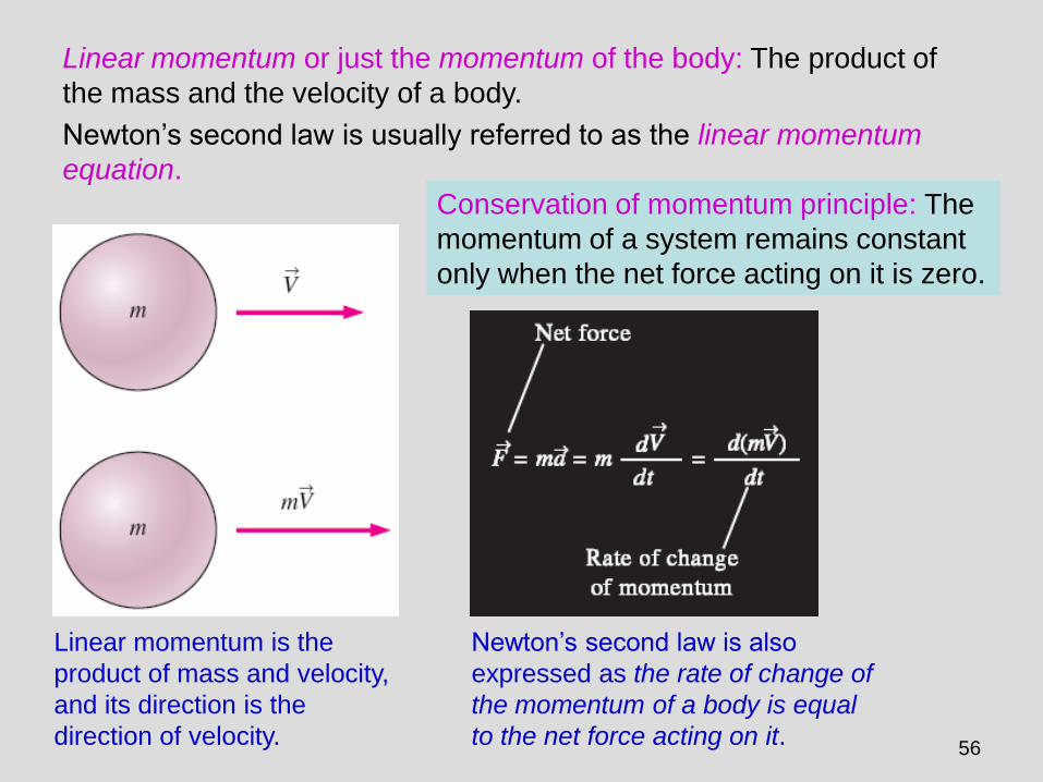
Linear momentum is the
product of mass and velocity,
and its direction is the
direction of velocity.
Newton’s second law is also
expressed as the rate of change of
the momentum of a body is equal
to the net force acting on it.
Linear momentum or just the momentum of the body: The product of
the mass and the velocity of a body.
Newton’s second law is usually referred to as the linear momentum
equation.
Conservation of momentum principle: The
momentum of a system remains constant
only when the net force acting on it is zero.
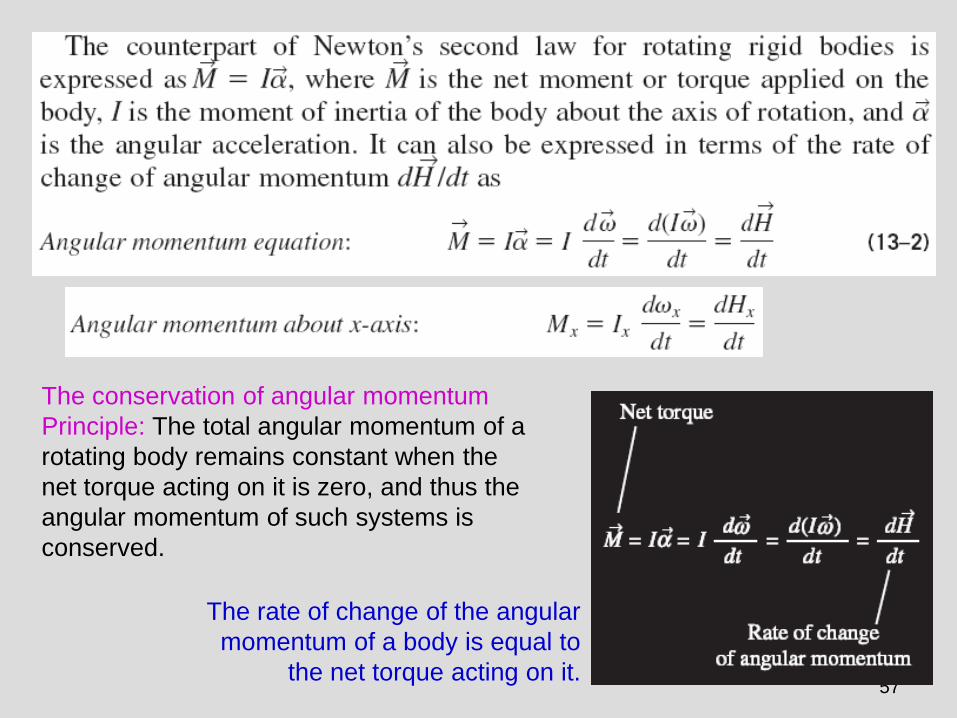
57
The rate of change of the angular
momentum of a body is equal to
the net torque acting on it.
The conservation of angular momentum
Principle: The total angular momentum of a
rotating body remains constant when the
net torque acting on it is zero, and thus the
angular momentum of such systems is
conserved.

58
CHOOSING A CONTROL VOLUME A control volume can be selected as any arbitrary
region in space through which fluid flows, and its
bounding control surface can be fixed, moving, and
even deforming during flow.
Many flow systems involve stationary hardware firmly
fixed to a stationary surface, and such systems are
best analyzed using fixed control volumes.
When analyzing flow systems that are moving or
deforming, it is usually more convenient to allow the
control volume to move or deform.
In deforming control volume, part of the control
surface moves relative to other parts.
59
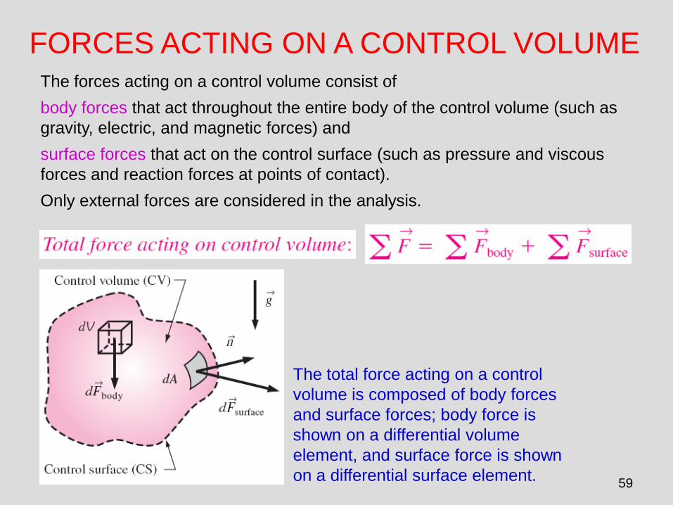
FORCES ACTING ON A CONTROL VOLUME The forces acting on a control volume consist of
body forces that act throughout the entire body of the control volume (such as
gravity, electric, and magnetic forces) and
surface forces that act on the control surface (such as pressure and viscous
forces and reaction forces at points of contact).
Only external forces are considered in the analysis.
The total force acting on a control
volume is composed of body forces
and surface forces; body force is
shown on a differential volume
element, and surface force is shown
on a differential surface element.
60
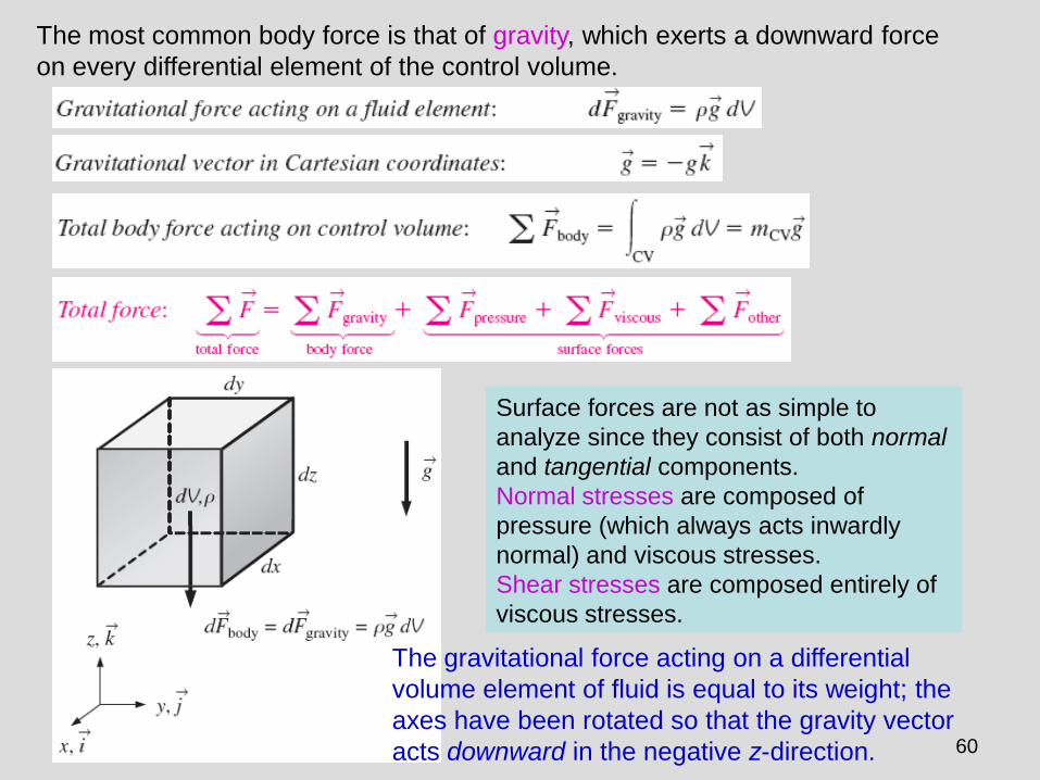
The most common body force is that of gravity, which exerts a downward force
on every differential element of the control volume.
Surface forces are not as simple to
analyze since they consist of both normal
and tangential components.
Normal stresses are composed of
pressure (which always acts inwardly
normal) and viscous stresses.
Shear stresses are composed entirely of
viscous stresses.
The gravitational force acting on a differential
volume element of fluid is equal to its weight; the
axes have been rotated so that the gravity vector
acts downward in the negative z-direction.

61
A common simplification in the application of Newton’s laws of motion is to
subtract the atmospheric pressure and work with gage pressures.
This is because atmospheric pressure acts in all directions, and its effect cancels
out in every direction.
This means we can also ignore the pressure forces at outlet sections where the
fluid is discharged to the atmosphere since the discharge pressure in such cases
is very near atmospheric pressure at subsonic velocities.
Atmospheric pressure acts in all directions, and thus it can be ignored when performing force balances since its effect cancels out in every direction.
Cross section through a faucet assembly, illustrating the importance of choosing a control volume wisely; CV B is much easier to work with than CV A.
62
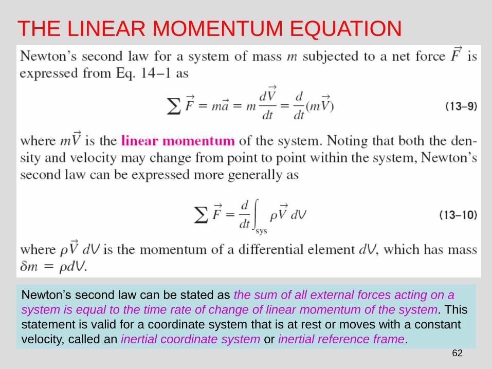
THE LINEAR MOMENTUM EQUATION
Newton’s second law can be stated as the sum of all external forces acting on a
system is equal to the time rate of change of linear momentum of the system. This
statement is valid for a coordinate system that is at rest or moves with a constant
velocity, called an inertial coordinate system or inertial reference frame.
63
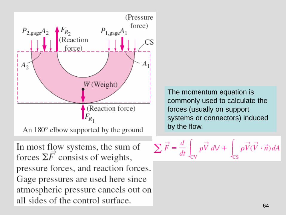
64
The momentum equation is
commonly used to calculate the
forces (usually on support
systems or connectors) induced
by the flow.
65
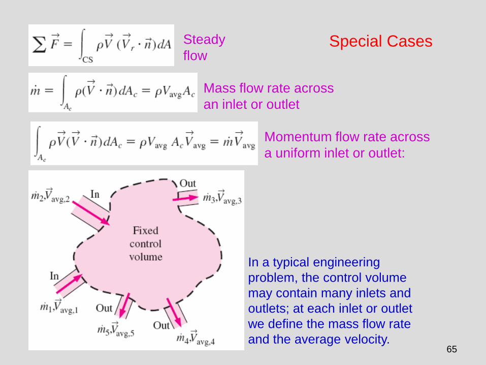
Special Cases Steady
flow
Mass flow rate across
an inlet or outlet
Momentum flow rate across
a uniform inlet or outlet:
In a typical engineering
problem, the control volume
may contain many inlets and
outlets; at each inlet or outlet
we define the mass flow rate
and the average velocity.

66
Examples of inlets or outlets in which the uniform flow
approximation is reasonable:
(a) the well-rounded entrance to a pipe,
(b) the entrance to a wind tunnel test section, and
(c) a slice through a free water jet in air.

67
Momentum-Flux Correction Factor,
The velocity across most inlets and outlets is not uniform.
The control surface integral of Eq. 13–13 may be converted into algebraic form using
a dimensionless correction factor , called the momentum-flux correction factor.
(13-13)
is always greater than or equal to 1.
is close to 1 for turbulent flow and
not very close to 1 for fully developed
laminar flow.

68
Steady Flow
The net force acting on the control volume during steady flow is equal to the
difference between the rates of outgoing and incoming momentum flows.
The net force acting on the control
volume during steady flow is equal to
the difference between the outgoing
and the incoming momentum fluxes.

69
Steady Flow with One Inlet and One Outlet
One inlet and
one outlet
Along x-
coordinate
A control volume with only one
inlet and one outlet.
The determination by vector
addition of the reaction force on
the support caused by a change
of direction of water.

70
Flow with No External Forces
In the absence of external forces, the rate of change of the
momentum of a control volume is equal to the difference between
the rates of incoming and outgoing momentum flow rates.
The thrust needed to lift the space
shuttle is generated by the rocket
engines as a result of momentum
change of the fuel as it is accelerated
from about zero to an exit speed of
about 2000 m/s after combustion.
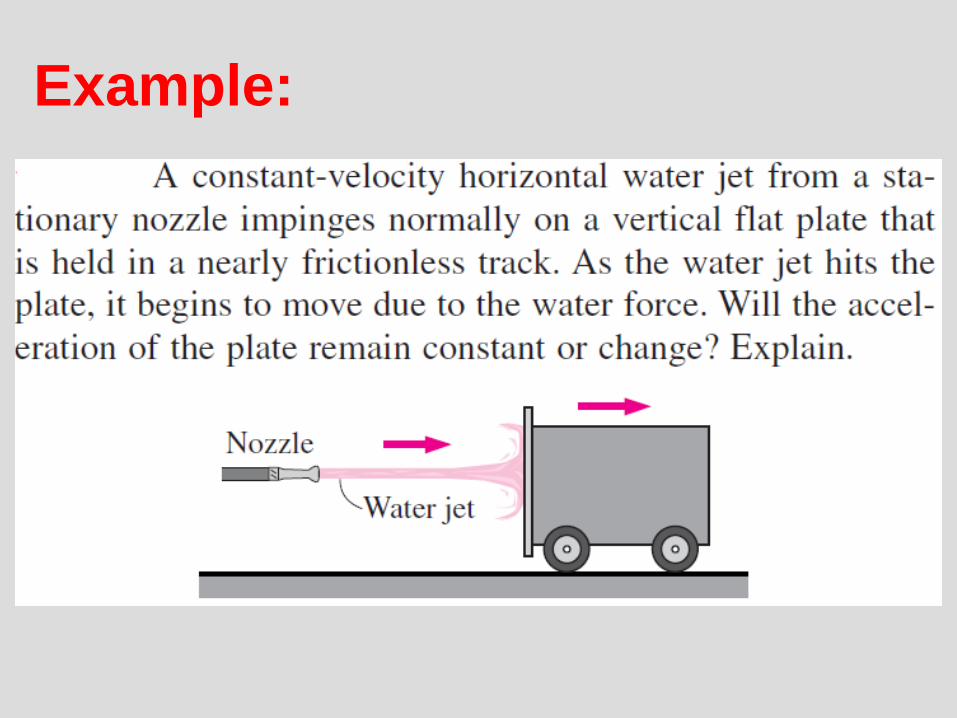
Example:

Example:

Example:

Example:

75
REVIEW OF ROTATIONAL MOTION AND
ANGULAR MOMENTUM Rotational motion: A motion during
which all points in the body move in
circles about the axis of rotation.
Rotational motion is described with
angular quantities such as the
angular distance , angular velocity
, and angular acceleration .
Angular velocity: The angular
distance traveled per unit time.
Angular acceleration: The rate of
change of angular velocity.
The relations between angular
distance , angular velocity ,
and linear velocity V.

76
• Newton’s second law requires that there must be a force acting in the
tangential direction to cause angular acceleration.
• The strength of the rotating effect, called the moment or torque, is proportional
to the magnitude of the force and its distance from the axis of rotation.
• The perpendicular distance from the axis of rotation to the line of action of the
force is called the moment arm, and the torque M acting on a point mass m at
a normal distance r from the axis of rotation is expressed as
I is the moment of inertia of the body
about the axis of rotation, which is a
measure of the inertia of a body
against rotation.
Unlike mass, the rotational inertia of
a body also depends on the
distribution of the mass of the body
with respect to the axis of rotation.
Torque
Analogy between corresponding
linear and angular quantities.

77
Angular momentum
Angular momentum
equation
Angular momentum of point mass m
rotating at angular velocity at
distance r from the axis of rotation.
The relations between angular
velocity, rpm, and the power
transmitted through a shaft.
Angular velocity
versus rpm
78
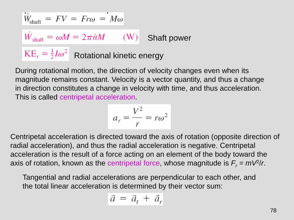
Shaft power
Rotational kinetic energy
During rotational motion, the direction of velocity changes even when its
magnitude remains constant. Velocity is a vector quantity, and thus a change
in direction constitutes a change in velocity with time, and thus acceleration.
This is called centripetal acceleration.
Centripetal acceleration is directed toward the axis of rotation (opposite direction of
radial acceleration), and thus the radial acceleration is negative. Centripetal
acceleration is the result of a force acting on an element of the body toward the
axis of rotation, known as the centripetal force, whose magnitude is Fr = mV2/r.
Tangential and radial accelerations are perpendicular to each other, and
the total linear acceleration is determined by their vector sum:

79
THE ANGULAR MOMENTUM EQUATION Many engineering problems involve the moment of the linear momentum of
flow streams, and the rotational effects caused by them.
Such problems are best analyzed by the angular momentum equation, also
called the moment of momentum equation.
An important class of fluid devices, called turbomachines, which include
centrifugal pumps, turbines, and fans, is analyzed by the angular
momentum equation.
The determination
of the direction of
the moment by the
right-hand rule.
A force whose line of
action passes through
point O produces zero
moment about point O.
80
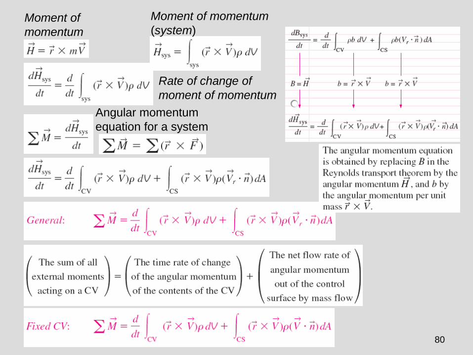
Moment of
momentum
Moment of momentum
(system)
Rate of change of
moment of momentum
Angular momentum
equation for a system
81
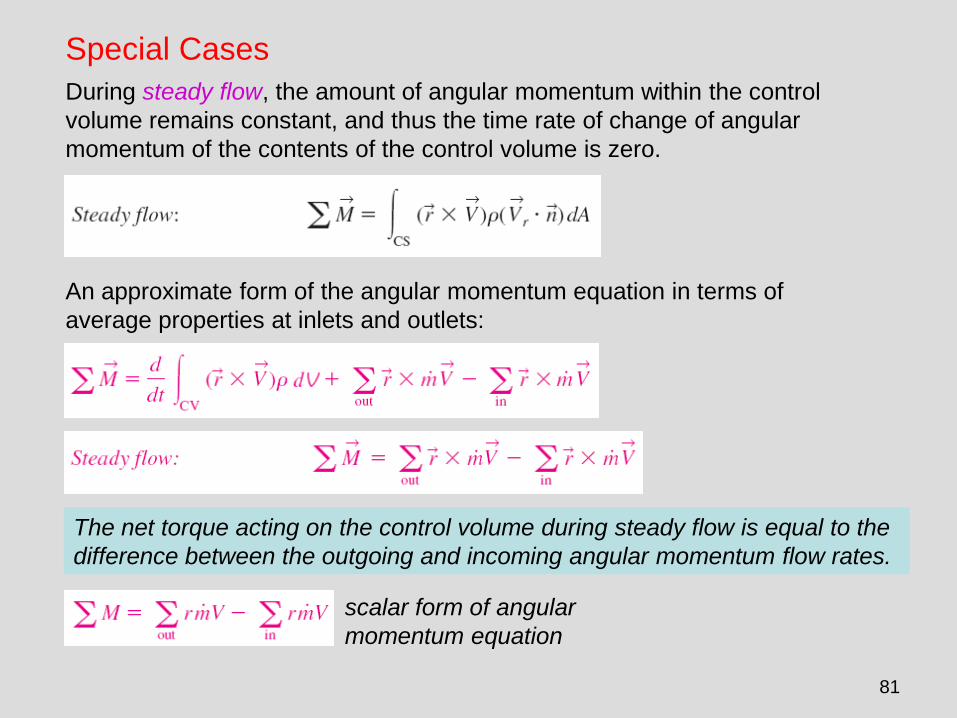
Special Cases
During steady flow, the amount of angular momentum within the control
volume remains constant, and thus the time rate of change of angular
momentum of the contents of the control volume is zero.
An approximate form of the angular momentum equation in terms of
average properties at inlets and outlets:
The net torque acting on the control volume during steady flow is equal to the
difference between the outgoing and incoming angular momentum flow rates.
scalar form of angular
momentum equation

82
Radial-Flow Devices
Radial-flow devices: Many rotary-flow devices such as centrifugal pumps and
fans involve flow in the radial direction normal to the axis of rotation.
Axial-flow devices are easily analyzed using the linear momentum equation.
Radial-flow devices involve large changes in angular momentum of the fluid
and are best analyzed with the help of the angular momentum equation.
Side and frontal views of a typical centrifugal pump.

83
An annular control
volume that encloses
the impeller section of
a centrifugal pump.
Euler’s turbine
formula
The conservation of mass equation for steady incompressible flow
angular momentum
equation
When
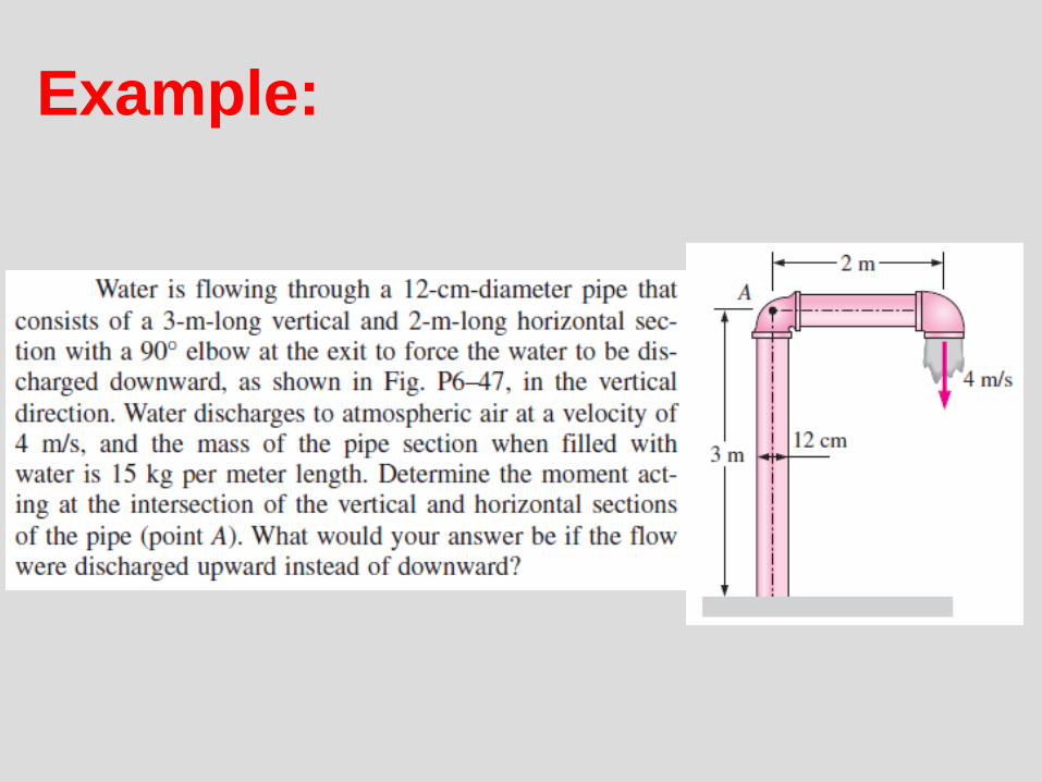
Example:

Example: