clark county fire code cod… · · 2015-10-05clark county fire code code amendments for adoption...
TRANSCRIPT
CLARK COUNTY FIRE CODE
CODE AMENDMENTS FOR ADOPTION OF 2009 INTERNATIONAL FIRE CODE
Effective July 5, 2011
Bertral T. Washington, Fire Chief
Clark County Fire Department 575 E. Flamingo Road
Las Vegas, Nevada 89119
Phone: (702) 455-7316 Web Page: http://www.clarkcountynv.gov/depts/fire
Original copy of ordinance on-file with Clark County Clerk’s office
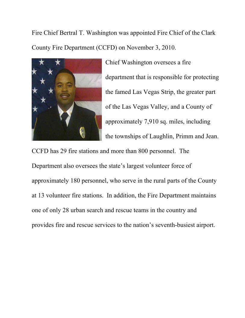
Fire Chief Bertral T. Washington was appointed Fire Chief of the Clark
County Fire Department (CCFD) on November 3, 2010.
Chief Washington oversees a fire
department that is responsible for protecting
the famed Las Vegas Strip, the greater part
of the Las Vegas Valley, and a County of
approximately 7,910 sq. miles, including
the townships of Laughlin, Primm and Jean.
CCFD has 29 fire stations and more than 800 personnel. The
Department also oversees the state’s largest volunteer force of
approximately 180 personnel, who serve in the rural parts of the County
at 13 volunteer fire stations. In addition, the Fire Department maintains
one of only 28 urban search and rescue teams in the country and
provides fire and rescue services to the nation’s seventh-busiest airport.

CCFD AMENDMENTS TO IFC 2009 EDITION IFC CHAPTER 1 “101.1 Title” is amended to read as follows:
101.1 Title. These regulations shall be known as the Fire Code of Clark County, hereinafter referred to as “this code”.
“101.2.1 Appendices” is amended to read as follows:
101.2.1 Appendices. Provisions in the appendices shall not apply unless specifically adopted. The following appendices are hereby adopted and are a part of this code: Appendix B – Fire-flow requirements for buildings, as amended Appendix C – Fire hydrant locations and distribution, as amended Appendix E - Hazard Categories Appendix H – Hazardous materials management plan (HMMP) and hazardous materials
inventory statement (HMIS) instructions Appendix J – Emergency responder radio coverage system, as amended Appendix K – Proprietary (self) monitoring, as amended Appendix L – Fire Protection Systems - Impairment and Systems out of Service, as amended
“101.6 Supplemental Rules and Regulations” is added to read as follows:
101.6 Supplemental rules and regulations. The chief is authorized to render interpretations of this code and to make and enforce rules and supplemental policies, regulations and guidelines in order to carry out the application and intent of its provisions. Such interpretations, rules, policies, regulations, and guidelines shall be in conformance with the intent and purpose of this code and shall be available to the public during normal business hours.
“102.7.1 Local codes” is aded to read as follows:
102.7.1 Local codes. The revised locally adopted codes listed below shall replace the listed referenced documents. References contained herein shall refer to the locally adopted codes.
1
0123456789
IBC-09 2009 International Building Code IMC-09 International Mechanical Code is replaced with 2009 Uniform Mechanical Code IPC-09 International Plumbing Code is replaced with 2009 Uniform Plumbing Code IRC-09 2009 International Residential Code
“104.9 Alternative materials and methods” is amended to read as follows:
104.9 Alternative materials and methods. The provisions of this code are not intended to prevent the installation of any material or to prohibit any method of construction not specifically prescribed by this code, provided that any such alternative has been approved. The fire code official is authorized to approve an alternative material or method of construction where the fire code official finds that the proposed design is satisfactory and complies with the intent of the provisions of this code, and that the material, method or work offered is, for the purposes intended, at least the equivalent of that prescribed in this code in quality, strength, effectiveness, fire resistance, durability and safety. The fire code official is authorized to require design submittals to be prepared by, and bear the stamp of, a Nevada registered design professional.
“105.1.1 Permits required” is amended to read as follows:
105.1.1 Permits required. Permits required by this code shall be obtained from the fire code official. Permit fees in accordance with the adopted Permit and Service Fee Schedule shall be paid prior to issuance of the permit. Issued permits shall be kept on the premises designated therein at all times and shall be readily available for inspection by the fire code official.
“105.1.4 Certificate of Insurance” is added to read as follows:
105.1.4 Certificate of Insurance. A valid Certificate of Insurance shall be submitted to, or be on file with, the fire code official when applying for a permit to conduct specific operations.
Exception: The requirement for an insurance certificate may be waived by the County’s Risk Manager.
105.1.4.1 Certificate Information Required. The certificate shall be issued by an insurance company authorized to conduct business in the State of Nevada, or be named on the list of authorized insurers maintained by the Nevada Department of Business and Industry, Division of Insurance.
The following information shall be provided on the certificate:
2

1. The contractor shall be named as the insured. If the insurance is provided by an individual, company or partnership other than the contractor, the contractor shall be named as an additional insured.
2. “Clark County, it’s agents, employees and volunteers” shall be named as both an additional insured and certificate holder
3. General liability limits, including contractual liability, in the minimum amounts specified below of the specific operation being conducted: a. To erect temporary membrane structures, tents, or canopies. See
Chapter 24: $2,000,000. b. To use explosive materials or to conduct pyrotechnic displays. See
Chapter 33: $2,000,000 Exception: The fire code official is authorized to reduce the liability limits to $1,000,000 for small private party blasting operations such as personal mining claims or agricultural uses. Under no circumstance will this include development related blasting activities, quarry blasting, construction blasting, or other similar large scale blasting operations.
c. To operate a special amusement building. See Chapter 9: $2,000,000. 105.1.4.2 Additional Insurance. Greater liability insurance amounts may be required in certain cases (such as building implosions) as deemed necessary by the fire code official.
“105.3.1 Expiration” is amended to read as follows:
105.3.1 Expiration. An operational permit shall remain in effect until reissued, renewed, or revoked or for such a period of time as specified in the permit, not exceeding one year from date of issuance. Construction permits shall automatically become invalid unless the work authorized by such permit is commenced within 180 days after its issuance, or if the work authorized by such permit is suspended or abandoned for a period of 180 days after the time the work is commenced. Before such work recommences, a new permit shall be first obtained and the fee to recommence work, if any, shall be one-half the amount required for a new permit for such work, provided no changes have been made or will be made in the original construction documents for such work, and provided further that such suspension or abandonment has not exceeded one year. Permits are not transferable and any changes in occupancy, operation, tenancy or ownership shall require a new permit to be issued.
“105.6.2 Amusement buildings” is amended to read as follows:
105.6.2 Amusement buildings. An operational permit is required to operate a special amusement building open to the public for 30 days or less.
“105.6.23 Hot work operations” is amended to read as follows:
3
105.6.23 Hot work operations. An operational permit is required for hot work including, but not limited to:
1. Public exhibitions and demonstrations where hot work is conducted. 2. Use of portable hot work equipment inside, upon, or within 10 feet of a structure.
Exception: Work that is conducted under a construction permit. 3. Fixed-site hot work equipment such as welding booths. 4. Hot work conducted within a hazardous fire area. 5. Application of roof coverings with the use of an open-flame device. 6. When approved, the fire code official shall issue a permit to carry out a Hot Work Program. This program allows approved personnel to regulate their facility’s hot work operations. The approved personnel shall be trained in the fire safety aspects denoted in this chapter and shall be responsible for issuing permits requiring compliance with the requirements found in Chapter 26. These permits shall be issued only to their employees or hot work operations under their supervision.
“105.6.32 Open flames and candles” is amended to read as follows:
105.6.32 Open flames and candles. An operational permit is required to use open flames or candles with assembly areas, dining areas of restaurants or drinking establishments. Annual permits for open flames and candles that are periodically used at facilities are acceptable where the permit application provides all conditions surrounding the use of the particular open flames or candles.
“105.6.40 Heliports, Helistops, and Emergency Landing Pads” is amended to read as follows:
105.6.40 Heliports, Helistops, and Emergency Landing Pads. An operational permit is required for the operation of a heliport, helistop, and/or emergency landing pad. See Chapter 11 and NFPA 418.
“105.6.47 Emergency responder radio coverage system” is added to read as follows:
105.6.47 Emergency responder radio coverage system. An operational permit is required to operate an emergency responder radio coverage system regulated by Chapter 5 and Appendix J.
“105.6.48 Filming” is added to read as follows:
4
105.6.48 Filming. An operational permit is required to film, or broadcast at a public studio, production location, or sound stage. See Section 321.
“105.6.49 Firewood” is added to read as follows:
105.6.49 Firewood. An operational permit is required to store firewood in excess of 50 cords. See Chapter 19.
“105.6.50 Flame Effects” is added to read as follows:
105.6.50 Flame effects. An operational permit is required to produce combustion through the use of flammable solids, liquids, or gases to produce thermal, physical, visual, or audible phenomenon for entertainment, exhibition, demonstration or simulation. See NFPA 160.
“105.6.51 Mobile fueling site” is added to read as follows:
105.6.51 Mobile fueling site. An operational permit is required to operate each site where mobile fueling takes place. See Chapter 34.
“105.6.52 Mobile fueling vehicle” is added to read as follows:
105.6.52 Mobile fueling vehicle. An operational permit is required to operate a mobile fueling vehicle. See Chapter 34.
“105.6.53 Monitoring facilities” is added to read as follows:
105.6.53 Monitoring facilities. An operation permit is required for any facility that remotely monitors electronic signals initiated by fire protection systems such as central or supervising facilities.
“105.6.54 Proprietary (self) monitoring” is added to read as follows:
105.6.54 Proprietary (self) monitoring. An operational permit is required to operate an onsite proprietary (self) monitoring fire alarm system. See Appendix K.
“105.6.55 Radioactive Materials” is added to read as follows:
5
105.6.55 Radioactive Materials. An operational permit is required to store or handle at any installation any amount of radioactive material for which a specific license from the Nuclear Regulatory Commission and/or Nevada State Health Division Radiation Control is required.
“105.6.57 Special Activity” is added to read as follows:
105.6.57 Special Activity. An operational permit is required at locations that operate Christmas tree lots, pumpkin patch lots, and similar activities. See Chapter 3.
“105.6.58 Tire storage” is added to read as follows:
105.6.58 Tire storage. An operational permit is required to store tires in excess of 1,000 cubic feet (28.3 m3). See Chapter 25.
“105.6.59 Wood pallets” is added to read as follows:
105.6.59 Wood pallets. An operational permit is required to store or rehabilitate pallets in an area exceeding 500 sq. ft. (46 m2) See Section 319.
“105.6.60 Asbestos removal” is added to read as follows:
105.6.60 Asbestos removal. To conduct asbestos-removal operations regulated by Chapter 14
“105.7.1 Fire suppression and extinguishing systems” is amended to read as follows:
105.7.1 Fire suppression and extinguishing systems. A construction permit is required for the following:
1. Installation of or modification to fire suppression and extinguishing system. 2. Replacement of recalled fire protection components.
Maintenance performed in accordance with this code is not considered a modification and does not require a permit.
“105.7.3 Compressed gases” is amended to read as follows:
105.7.3 Compressed gases. When the compressed gases in use or storage exceed the amounts listed in Table 105.6.8, a construction permit is required to install, repair
6
damage to, abandon, remove, place temporarily out of service or close or substantially modify a compressed gas system.
Exceptions: 1. Routine maintenance. 2. For emergency repair work performed on an emergency basis, application
for permit shall be made within two working days of commencement of work.
A construction permit is required to install, extend, alter, or modify a medical gas system.
Exception: Level 3 compressed air and/or piped vacuum systems as defined by NFPA 99, Standard for Health Care Facilities.
“105.7.4 Cryogenic fluids” is amended to read as follows:
105.7.4 Cryogenic fluids. A construction permit is required for installation of or alteration to outdoor stationary cryogenic fluid storage systems and for fog effect systems that utilize CO2 or cryogenic fluids where the system capacity exceeds the amounts listed in Table 105.6.8 or Table 105.6.10. Maintenance performed in accordance with this code is not considered a modification and does not require a permit.
“105.7.5 Fire alarm and detection systems, related equipment and dedicated function fire alarm systems (i.e., monitoring)” is amended to read as follows:
105.7.5 Fire alarm and detection systems, related equipment and dedicated function fire alarm systems (i.e., monitoring). A construction permit is required for the following:
1. Installation of or modification (including but not limited to: extending; reprogramming; upgrading field programmable EPROM, or altering) to fire alarm and detection systems, related equipment, and dedicated function fire alarm systems.
2. Replacement of recalled fire protection components. 3. Control equipment replacement due to equipment failure.
Maintenance performed in accordance with this code is not considered a modification and does not require a permit.
“105.7.11 Fire Hydrants and Associated Supply Piping” is amended to read as follows:
105.7.11 Fire Hydrants and Associated Supply Piping. A construction permit is required for the installation or modification of fire hydrants, including temporary hydrants, and the associated supply piping.
7
“105.7.15 Access gates” is added to read as follows:
105.7.15 Access gates. A construction permit is required for the installation of or modification to each access gate (including both manual and automatic gates) obstructing a fire apparatus access road. See Chapter 5
“105.7.16 Emergency responder radio coverage system” is added to read as follows:
105.7.16 Emergency responder radio coverage system. A construction permit is required for installation of or modification to emergency responder radio coverage systems and related equipment regulated by Chapter 5 and Appendix J.
“105.7.17 Fire apparatus access road plan” is added to read as follows:
105.7.17 Fire apparatus access road plan. A construction permit is required for the installation of or modification to a fire apparatus access road required for access to a protected premise. See Chapter 5 and Appendix C.
“105.7.18 Fire Protection Report” is added to read as follows:
105.7.18 Fire Protection Report. A permit is required for the review and approval of a Fire Protection (Life Safety) Report. See Chapter 9.
“105.7.20 Heliports, Helistops, and Emergency Landing pads” is added to read as follows:
105.7.20 Heliports, Helistops, and Emergency Landing pads. A construction permit is required for the installation of or modification to a heliport, helistop, and/or emergency landing pad. See Chapter 11 and NFPA 418.
“105.7.21 Radioactive Materials” is added to read as follows:
105.7.21 Radioactive Materials. A construction permit is required to store or handle at any installation any amount of radioactive material for which a specific license from the Nuclear Regulatory Commission and/or Nevada State Health Division Radiation Control is required.
“105.7.23 Smoke Control System Control Panel” is added to read as follows:
8

105.7.23 Smoke Control System Control Panel. A construction permit is required for the installation of or modification to a smoke control system control panel. See Chapter 9.
“105.7.24 Smoke Removal System Control Panel” is added to read as follows:
105.7.24 Smoke Removal System Control Panel. A construction permit is required for the installation of or modification to a smoke removal system control panel. See Chapter 9.
“105.7.25 Water tanks” is added to read as follows:
105.7.25 Water tanks A construction permit is required for the installation of or modification to a water tank used for supply of a fire protection system. See Chapter 9 and NFPA 22.
Exception: Permits are not required for installation of tanks controlled by a water purveyor governed by the Nevada Public Service Commission, a State of Nevada charter, or other public franchise.
“108 Board of Appeals” is deleted in its entirety. “111.4 Failure to comply” is amended to read as follows:
111.4 Failure to comply. Any person who shall continue any work after being served with a stop work order, except such work as that person is directed to perform to remove a violation or unsafe condition, shall be liable to a fine as determined by the authority having jurisdiction.
“113.6 Permit and Service Fee Schedule” is added to read as follows:
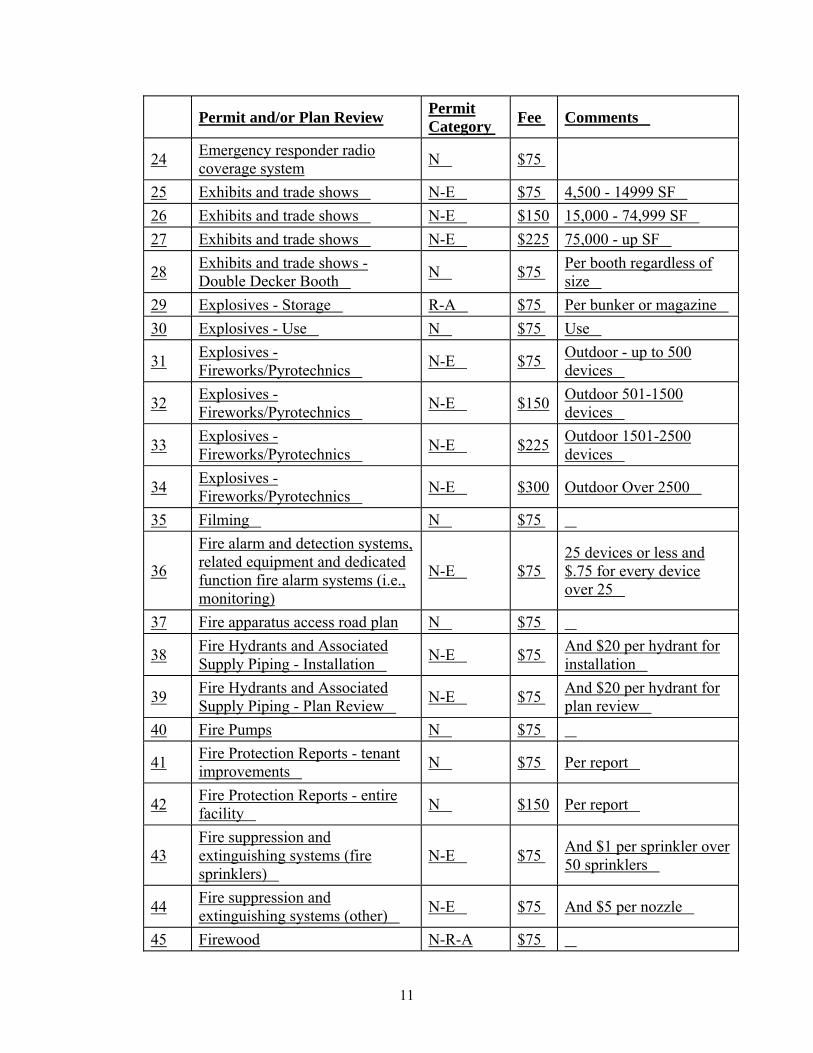
113.6 Permit and Service Fee Schedule. Fees for permits, inspections and other services shall be as set forth in the Permit and Service Fee Schedule, as adopted and amended from time to time by the Commission of Clark County. Permits, plan reviews and other services shall be charged the fees identified in Table 113-A and Table 113-B.
Table 113-A
Permit and/or Plan Review Permit Category Fee Comments
1 Access Gates N $75 Per gate (automatic or manual)
9

Permit and/or Plan Review Permit Category Fee Comments
2 Aerosol Products - excess of 500 lbs. R-A-E $75 Minimum fee $75 See
Permit Calculation Table
3 Aviation Facilities, Aircraft repair hangar R-A-E $150 Group 1 & 2 - See NFPA
#409
4 Aviation Facilities, Aircraft repair hangar R-A-E $75 Group 3 & 4
5 Aviation Facilities, Aircraft refueling vehicles R-A $75
6 Amusement Buildings - Temporary (less than 30 days on any single property)
N $75 ie. Haunted Houses
7 Asbestos removal N $75 8 Battery systems R-A $75 9 Carnivals/Fairs N $75 10 Cellulose nitrate film R-A $75
11 Combustible dust-producing operations R-A-E $75 2,500 - 10,000 SF of use
area
12 Combustible dust-producing operations R-A-E $150 Over 10,000 SF of use
area 13 Combustible fibers R-A $75
14 Compressed gas/Medical gas R-A-E $75 Minimum fee $75 See Permit Calculation Table
15 Covered mall buildings N $75 Placing/constructing Kiosk and other combustibles
16 Covered mall buildings N $75 Temporary use as place of assembly
17 Covered mall buildings N $75 Use open flame
18 Covered mall buildings N $75 Display liquid/gas fueled vehicles
19 Cutting and Welding N-R-A $75 Per location
20 Cryogenic Fluids R-A-E $75 Minimum fee $75 See Permit Calculation Table
21 Dry cleaning plants R-A-E $225 Type I and II
22 Dry cleaning plants R-A-E $150 Type IIIA & IIIB 23 Dry cleaning plants R-A-E $75 Type IV and V
10
Permit and/or Plan Review Permit Category Fee Comments
24 Emergency responder radio coverage system N $75
25 Exhibits and trade shows N-E $75 4,500 - 14999 SF 26 Exhibits and trade shows N-E $150 15,000 - 74,999 SF 27 Exhibits and trade shows N-E $225 75,000 - up SF
28 Exhibits and trade shows - Double Decker Booth N $75 Per booth regardless of
size 29 Explosives - Storage R-A $75 Per bunker or magazine 30 Explosives - Use N $75 Use
31 Explosives - Fireworks/Pyrotechnics N-E $75 Outdoor - up to 500
devices
32 Explosives - Fireworks/Pyrotechnics N-E $150 Outdoor 501-1500
devices
33 Explosives - Fireworks/Pyrotechnics N-E $225 Outdoor 1501-2500
devices
34 Explosives - Fireworks/Pyrotechnics N-E $300 Outdoor Over 2500
35 Filming N $75
36
Fire alarm and detection systems, related equipment and dedicated function fire alarm systems (i.e., monitoring)
N-E $75 25 devices or less and $.75 for every device over 25
37 Fire apparatus access road plan N $75
38 Fire Hydrants and Associated Supply Piping - Installation N-E $75 And $20 per hydrant for
installation
39 Fire Hydrants and Associated Supply Piping - Plan Review N-E $75 And $20 per hydrant for
plan review 40 Fire Pumps N $75
41 Fire Protection Reports - tenant improvements N $75 Per report
42 Fire Protection Reports - entire facility N $150 Per report
43 Fire suppression and extinguishing systems (fire sprinklers)
N-E $75 And $1 per sprinkler over 50 sprinklers
44 Fire suppression and extinguishing systems (other) N-E $75 And $5 per nozzle
45 Firewood N-R-A $75
11

Permit and/or Plan Review Permit Category Fee Comments
46 Flame Effects N-R-A $75
47 Flammable and combustible liquids -Underground Storage/Use
N-E $75 Minimum fee $75 See Permit Calculation Table
48 Flammable and combustible liquids -Aboveground Storage/Use
N-R-A-E $75 Minimum fee $75 See Permit Calculation Table
49 Floor Finishing N $75
50 Fruit and crop ripening R-A $75
51 Fumigation and thermal insecticidal fogging R-A $75 Business location only
52 Hazardous Materials and/or HPM Facilities R-A-E $75 Minimum fee $75 See
Permit Calculation Table
53 Heliports, Helistops, and Emergency Landing Pads R-A $75
54 High-piled storage R-A-E $75 501 - 12,000 SF 55 High-piled storage R-A-E $150 12,001 - 100,000 SF 56 High-piled storage R-A-E $225 Over 100,000 SF
57 Hot-work operations N-R-A $75 Per location, mobile, fixed, combination
58 Industrial Ovens R-A $75
59 Liquid- or gas-fueled vehicles or equipment in assembly buildings
N-R-A $75 Per occurrence, not per vehicle
60 LP gases N $75 Single family residence
61 LP gases N-R-A-E $75 Commercial aggregate, 125 - 2000 gallons
62 LP gases N-R-A-E $150 Over 2,000 gallons
63 Lumber yards and woodworking plants R-A $75
64 Magnesium R-A $75 Magnesium working
65 Miscellaneous Combustible Storage R-A $75
66 Mobile Fueling Vehicle N-R-A $75 67 Mobile Fueling Site N-R-A $75 68 Monitoring Facilities N $75 See Fire Alarm
12

Permit and/or Plan Review Permit Category Fee Comments
69 Open burning N $75 Per location
70 Open Flames and Candles N-R-A $75
Per submittal, i.e. Candles, gelled alcohol flames (sterno), portable stoves, etc.
71 Open Flames and torches N-R-A $75 Per location
72 Organic coatings R-A-E $75 Minimum fee $75 See Permit Calculation Table
73 Places of Assembly N-R-A-E $75 0 - 14,999 SF 74 Places of Assembly N-R-A-E $150 15,000 - 74,999 SF 75 Places of Assembly N-R-A-E $225 75,000 - up SF 76 Proprietary(self) monitoring R-A $75
77 Pyrotechnic special effects materials N $75 Booth
78 Pyrotechnic special effects materials - Fireworks/Pyrotechnics
N-R-A-E $75 Indoor - up to 100 devices
79 Pyrotechnic special effects materials - Fireworks/Pyrotechnics
N-R-A-E $150 Indoor Over 100
80 Pyroxylin (cellulose nitrate) Plastics Storage R-A $75
81 Radioactive materials R-A $75
82 Refrigeration equipment R-A-E $75 Minimum fee $75 See Permit Calculation Table
83 Repair garages and motor vehicle fuel-dispensing station R-A-E $75 12 dispensers or less
84 Repair garages and motor vehicle fuel-dispensing station R-A-E $150 Over 12 dispensers
85 Repair garages and motor vehicle fuel-dispensing station R-A $75 Repair garage facility
86 Smoke control system(s) N $75 Panel 87 Smoke removal system(s) N $75 Panel
88 Special Activity Lot N $75
Per activity, i.e. Christmas Tree Lot, Pumpkin Patch, Hay-Ride Lot, etc.
13
Permit and/or Plan Review Permit Category Fee Comments
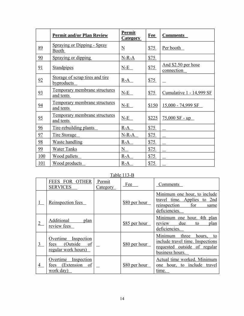
89 Spraying or Dipping - Spray Booth N $75 Per booth
90 Spraying or dipping N-R-A $75
91 Standpipes N-E $75 And $2.50 per hose connection
92 Storage of scrap tires and tire byproducts R-A $75
93 Temporary membrane structures and tents N-E $75 Cumulative 1 - 14,999 SF
94 Temporary membrane structures and tents N-E $150 15,000 - 74,999 SF
95 Temporary membrane structures and tents N-E $225 75,000 SF - up
96 Tire-rebuilding plants R-A $75 97 Tire Storage N-R-A $75 98 Waste handling R-A $75 99 Water Tanks N $75 100 Wood pallets R-A $75 101 Wood products R-A $75
Table 113-B
FEES FOR OTHER SERVICES
Permit Category Fee Comments
1 Reinspection fees $80 per hour
Minimum one hour, to include travel time. Applies to 2nd reinspection for same deficiencies.
2 Additional plan review fees $85 per hour
Minimum one hour. 4th plan review due to plan deficiencies.
3 Overtime Inspection fees (Outside of regular work hours)
$80 per hour
Minimum three hours, to include travel time. Inspections requested outside of regular business hours.
4 Overtime Inspection fees (Extension of work day)
$80 per hour Actual time worked. Minimum one hour, to include travel time.
14

FEES FOR OTHER SERVICES
Permit Category Fee Comments
5 Expedite plan review fees
1x permit fee, or $85 per hour, which ever is greater
*Except Fire Protection Reports
6 Late submittal fee 1x permit fee
Must be paid anytime a permit request is received less than 3 days prior to the event or activity.
7 Engine Company Standby $300 per hour
Per hour, minimum 4 hours. Per apparatus or unit.
8 Sprinkler Design Flow Test N $75 To establish basis for fire
sprinkler system design
9 Requests for Search of Fire Prevention Records
$80 per hour
Minimum $80 per address searched. Includes tasks such as environmental site assessments, outstanding violations, etc.
10 Copies $1 per page
Requests for copies of various Fire Prevention Bureau documents.
11
False/Nuisance Alarm(s) Fee $500
12
Same-Day Inspection Fee 1x permit fee
Also responsible for inspector's overtime.
13
Expedite fee - Fire Protection Reports N
1x permit fee plus $85 an hour plan review fee
Per report
14 Next Day Plan Review N $160
15 Express Plan Review N $160 N - Non renewable (Temporary Use) R – Renewable (Permanent) A - Annual E - Escalating
IFC CHAPTER 2 “201.3 Terms defined in other codes” is amended to read as follows:
15
201.3 Terms defined in other codes. Where terms are not defined in this code and are defined in the other codes adopted by this jurisdiction, such terms shall have the meanings ascribed to them as in those codes.
“202 FALSE ALARM” is amended to read as follows:
FALSE ALARM is the activation or reporting of an alarm for which no such alarm condition, fire or emergency actually exists. Additionally, False Alarm is the willful and knowing initiating or transmission of a signal, message or other notification of an event of fire when no such danger exists.
“202 Group I-4, day care facilities” is amended to read as follows:
Group I-4, day care facilities. This group shall include buildings and structures occupied by persons of any age who receive custodial care for less than 24 hours by individuals other than parents or guardians, relatives by blood, marriage or adoption, and in a place other than the home of the person cared for. A facility such as the above with six or fewer persons shall be classified as a Group R-3 or shall comply with the International Residential Code in accordance with Section 101.2 of the International Building Code. Places of worship during religious functions are not included.
Adult care facility. A facility that provides accommodations for less than 24 hours for more than five unrelated adults and provides supervision and personal care services shall be classified as Group I-4.
Exception: Where the occupants are capable of responding to an emergency situation without physical assistance from the staff, the facility shall be classified as Group R-3.
Child care facility. A facility that provides supervision and personal care on less than a 24-hour basis for more than six children 2½ years of age or less shall be classified as a Group I-4.
Exception: A child day care facility that provides care for more than six but no more than 100 children 2½ years or less of age, where the rooms in which the children are cared for are located on a level of exit discharge serving such rooms and each of these childe care rooms has an exit door directly to the exterior, shall be classified as Group E.
“202 Residential Group R” is amended to read as follows:
Residential Group R. Residential Group R includes, among others, the use of a building or structure, or a portion thereof, for sleeping purposes when not classified as an Institutional Group I or when not regulated by the International Residential Code in
16

accordance with Section 101.2 of the International Building Code. Residential occupancies shall include the following: R-1 Residential occupancies containing sleeping units where the occupants are primarily transient in nature, including: Boarding houses (transient) Hotels (transient) Motels (transient) Congregate living facilities (transient) with 10 or fewer occupants are permitted to comply with the construction requirements for Group R-3. R-2 Residential occupancies containing sleeping units or more than two dwelling units where the occupants are primarily permanent in nature, including: Apartment houses Boarding houses (nontransient) Condominiums (nontransient) Convents Dormitories Fraternities and sororities Hotels (nontransient) Live/work units Monasteries Motels (nontransient) Vacation timeshare properties Congregate living facilities with 16 or fewer occupants are permitted to comply with the construction requirements for Group R-3. R-3 Residential occupancies where the occupants are primarily permanent in nature and not classified as Group R-1, R-2, R-4 or I, including:
Buildings that do not contain more than two dwelling units. Adult care facilities that provide accommodations for five or fewer persons of any age for less than 24 hours. Child care facilities that provide accommodations for six or fewer persons of any age for less than 24 hours.
Congregate living facilities with 16 or fewer persons. Adult care and child care facilities that are within a single-family home are permitted to comply with the International Residential Code. R-4 Residential occupancies shall include buildings arranged for occupancy as residential care/assisted living facilities including more than five but not more than 16 occupants, excluding staff. Group R-4 occupancies shall meet the requirements for construction as defined for Group R-3, except as otherwise provided for in this code or shall comply with the International Residential Code, provided the building is protected by an automatic sprinkler system installed in accordance with Section 903.2.8.
“202 SMOKE CONTROL, DEDICATED SYSTEMS” is added to read as follows:
17
SMOKE CONTROL, DEDICATED SYSTEMS. Dedicated smoke-control systems are intended for the purpose of smoke control only. They are separate systems of air moving and distribution equipment that do not function under normal building operating conditions. Upon activation, these systems operate specifically to perform the smoke-control function.
“202 SMOKE CONTROL, NON-DEDICATED SYSTEMS” is added to read as follows:
SMOKE CONTROL, NON-DEDICATED SYSTEMS. Non-dedicated systems are those that share components with some other system(s) such as the building HVAC system. Activation causes the system to change its mode of operation to achieve the smoke-control objectives.
IFC CHAPTER 3
“307.2 Permits required” is amended to read as follows:
307.2 Permit required. A permit shall be obtained from the fire code official in accordance with Section 105.6 prior to kindling a fire for recognized silvicultural or range or wildlife management practices, or prevention or control of disease or pests. Application for such approval shall only be presented by and permits issued to the owner of the land upon which the fire is to be kindled.
“307.4.1 Bonfires” is amended to read as follows:
307.4.1 Bonfires. Bonfires are prohibited. “307.4.4 Commercial Barbeques” is added to read as follows:
307.4.4 Commercial Barbecue. Barbecue pits used for commercial cooking operations in buildings shall be constructed as commercial food heat-processing equipment in accordance with the Mechanical Code. See also Section 904. Barbecue pits in outdoor locations shall be constructed of concrete or approved noncombustible materials and shall not be located within 10 feet (3048 mm) of combustible walls or roofs or other combustible material.
“308.1.4 Open-flame cooking devices” is amended to read as follows:
308.1.4 Open-flame cooking devices. Charcoal burners and other open-flame cooking devices, including electric barbecues that produce open flames, shall not be operated on combustible balconies or within 10 feet (3048 mm) of combustible construction.
18
Exception: One- and two-family dwellings
“311.2.2 Fire protection” is amended to read as follows:
311.2.2 Fire protection. Sprinkler and standpipe systems, including monitoring, shall be maintained in an operable condition at all times. The following exceptions may be used after obtaining approval from the fire code official. Exceptions:
1. When the premises have been cleared of all combustible materials and debris and in the opinion of the fire code official, the type of construction, fire separation distance and security of the premises do not create a fire hazard.
2. Where the buildings will not be heated and fire protection systems will be exposed to freezing temperatures, fire alarm and sprinkler systems are permitted to be placed out of service and standpipes are permitted to be maintained as dry systems (without an automatic water supply), provided the building has no contents or storage, and windows, doors and other openings are secured to prohibit entry by unauthorized persons.
“314.3 Highly combustible goods” is amended to read as follows:
314.3 Highly combustible goods. The display of highly combustible goods, including but not limited to fireworks, flammable or combustible liquids, liquefied flammable gases, oxidizing materials, pryroxylin, plastics and agricultural goods in main exit access aisles, corridors covered malls, or within 5 feet (1524 mm) of entrances to exits and exterior exit doors is prohibited.
“SECTION 318 EXHIBITIONS AND TRADE SHOWS”, is added to read as follows:
SECTION 318 EXHIBITIONS AND TRADE SHOWS 318.1 General. Indoor Exposition and Trade Show Facilities are addressed in this section. These include, but are not limited to exhibition halls, convention general sessions, association meetings, product convention showrooms; trade shows with or without booths, and political conventions that constitute temporary assembly uses. An operational permit shall be obtained in accordance with Section 105.6. Permits shall be in accordance with this section and the established assembly guidelines. 318.2 Exhibits (Booths). Exhibits (booths) shall comply with 318.2.1 through 318.2.5. 318.2.1 Automatic Sprinklers 318.2.1.1 Single-level exhibit booths exceeding 1,000 sq. ft. (93 sq. m.) and covered with a ceiling shall be protected by automatic fire sprinklers installed within the booth.
19
318.2.1.2 Each level of multi-level exhibit booths shall be protected by an automatic fire sprinkler system installed within the booth where the accessible floor area of any level is greater than 1,000 sq ft. (93 sq. m). 318.2.1.3 The water supply and piping for the fire sprinkler protection for exhibit booths shall be an approved temporary means provided by an existing standpipe system or an existing fire sprinkler system. 318.2.1.4 Hydraulic calculations shall be provided to the fire code official when the sprinklers required by Section 318.2.1.1 and 318.2.1.2 are supplied by the standpipe system or in a hydraulically most remote location as defined by the currently adopted edition of Standard for the Installation of Sprinklers, NFPA 13. 318.2.2 Horizontal Separation between Booths. A covered exhibit booth(s) that does not require fire sprinklers shall be separated by a distance of not less than 8 ft. (2.4 m) from any other covered exhibit booth(s) where the aggregate ceiling exceeds 1,000 sq. ft. (93 sq. m.). 318.2.3 Travel Distance within Booths. The travel distance within the exhibit booth or exhibit enclosure to an exit access aisle shall not exceed 50 ft. (15 m). 318.2.4 Means of Egress from Multi-Level Booths. The upper deck of multi-level exhibit booths exceeding 300 sq. ft. (28 sq. m.) shall have not less than two remote means of egress. 318.2.5 Construction Materials. Exhibit booths shall be constructed using any of the following:
(1) Noncombustible materials (2) Wood exceeding ¼ in. (6.3 mm) nominal thickness (3) Wood that is pressure-treated, fire-retardant wood meeting the requirements of NFPA
703, Standard for Fire Retardant-Treated Wood and Fire-Retardant Coatings for Building Materials.
(4) Flame-retardant materials complying with NFPA 701, Standard Methods of Fire Tests for Flame Propagation of Textiles and Films
(5) Textile wall coverings, such as carpeting and similar products used in wall or ceiling finishes complying with Section 803.5.1 of the IFC.
(6) Plastics limited to a Class A flame spread index. (7) Foamed plastics and materials containing foamed plastics complying with Section
807.4.2.1 of the IFC. (8) Cardboard, honeycombed paper, and other combustible materials having a heat
release rate for any single fuel package that does not exceed 150 kW where tested in accordance with UL 1975, Standard for Fire Tests for Foamed Plastics Used for Decorative Purposes.
(9) Alternate materials as approved by the fire code official.
318.3 Decorative Curtains, and Textiles 318.3.1 Curtains, drapes, and textiles used in temporary exhibitions and trade shows shall comply with Section 318, and shall not be required to comply with Section 807 Curtains, drapes and textiles shall comply with Standard Method of Fire Tests for Flame Propagation of Textiles and Films, NFPA 701, Test Method 2. Compliance shall be indicated by a tag affixed to each curtain, drape, or textile. The tag shall be affixed by the owner of the material after gaining assurance that the material is inherently flame
20
retardant, provided with current flame retardant treatment, or otherwise is compliant with NFPA 701. The tag shall indicate the name of the owner of the material and a statement indicating compliance with the Fire Code. The fire code official is authorized to conduct a field test in accordance with the current edition of NFPA 705, Recommended Practice for a Field Flame Test of Textiles and Films, on any curtain, drape or textile installed. 318.3.2 Curtains, drapes and textiles shall comply with Standard Method of Fire Tests for Flame Propagation of Textiles and Films, NFPA 701, Test Method 2. 318.3.3 Curtains, drapes or textiles shall not be installed to cover exit signs, means of egress components, sprinklers, strobes, horn-strobes, standpipe outlets, hose cabinets, fire extinguishers, or any other fire protection equipment.
Exception: Free-standing partitions situated in a manner to permit the minimum required egress width to one or both sides of the partition shall be permitted. The paths of egress provided around the partition shall be marked by exit signs complying with Chapter 10.
318.3.4 Ceiling suspended curtains drapes and textiles in exhibition spaces are to have a minimum of 18 inches of clear space between the top of the material and the sprinkler deflector.
Exception: Clearance between the ceiling and the top of the curtain, drape or textile is not required when the curtain, drape, or textile is within 6 inches of a full-height wall.
318.3.5 The amount of temporary ceiling hung curtains, drapes or textiles in exhibition spaces equipped throughout with automatic sprinklers shall not be limited and shall comply with 318.3.1 through 318.3.3. 318.4 Demonstration Cooking. Demonstration cooking and food warming in exhibition spaces shall comply with the following: 1. All cooking appliances shall be listed or approved by a nationally recognized testing
agency. 2. All cooking equipment is to be operated according to the manufacturers’
recommendations and operating instructions. Equipment recommended for outdoor use shall not be used indoors.
3. All cooking equipment (deep fat fryers and woks) operations using combustible oils shall meet all of the following criteria: a. Metal lids sized to cover the horizontal cooking surface are to be provided. b. The cooking surface is limited to 288 sq in (two sq ft). c. Cooking equipment exceeding 288 sq in aggregate surface area shall be provided
with an automatic extinguishing system installed according to NFPA 17A. d. Cooking equipment exceeding 288 sq in shall be provided with a mechanical
exhaust system in accordance with the mechanical code. e. The fryer is to be separated from all other equipment by a distance not less than
24 in. f. These cooking displays must be separated from all other combustibles by a
distance not less than 10 ft. g. The volume of cooking oil per appliance is not to exceed 3 gal. h. The volume of cooking oil per booth is not to exceed 8 gal. i. Deep fat fryers shall be electrically powered and have a shut-off switch.
21
4. Class-K fire extinguishers shall be provided within 30-ft of each cooking operation in accordance with 904.11.5.
5. Solid fuel cooking equipment shall be protected in accordance with the mechanical code.
6. LP-gas used for displays and demonstrations shall be in accordance with section 3803.2.1.5.
318.5 Plans. Plans for the exhibition or trade show shall be submitted to the authority having jurisdiction for approval, along with application for an operational permit, prior to setting up any exhibit. The plans shall show all pertinent details of the proposed exposition which shall include the following as applicable: 1. Overall floor plan (either drawn to scale or dimensioned properly) 2. Egress analysis showing conformance with chapter 10 of the IFC 3. Seating arrangements and/or table and chair configurations 4. Locations of all exhibits (booths, aisles and exits) 5. Locations of temporary walls, partitions, or curtains 6. Lobby and registration area usage 7. Location of temporary platforms (along with any intended use beneath the platform) 8. Location of fire protection equipment (e.g. extinguishers, fire alarm devices, hose
cabinets, etc.) 9. Temporary fire sprinkler and fire alarm system/devices to be installed (note: This
requires a separate installation permit) 10. Copy of excerpt from show management information guide serving notice that all
exhibits shall comply with applicable codes and shall have all necessary Fire Code permits.
“SECTION 319 Wood and Plastic Pallet Storage and Rehabilitation”, is added to read as follows:
319.1 General. New and existing facilities with either storage or rehabilitation of pallets shall be in accordance with Sections 319.1 thru 319.6.3 and Section 1903. 319.2 Permits. An operational permit is required for new and existing facilities which store more than fifty (50) idle pallets on site, either inside or outside of a building. For a commercial pallet yard, a site plan demonstrating compliance with Section 319 shall be submitted for review and approval prior to issuance of the operational permit. 319.3 Fire Flow. The minimum required fire flow in pallet storage yards shall not be less than 2,000 gpm (7571 L/m). For storage yards with stable piles greater that 6,200 sq. ft. (576 m2) the required fire flow will follow the requirements of Appendix B, Table B105.1 for Type V-B construction. Pallet storage yards shall not exceed the available fire hydrant flow and spacing. 319.4 Fire Hydrants. Fire hydrants required for fire flow purposes for pallet storage array(s) shall be provided within three hundred (300) feet (152.4m) of hose lay to all pallets. 319.5 Fire Department Access. Fire apparatus access roads in accordance with Section 503 shall be located within one hundred fifty (150) feet (45,720mm) of all portions of
22

the pallet storage array(s). Permanent delineation of on-site fire apparatus access roads shall be provided as required by the fire code official. 319.6 Idle Pallet Storage 319.6.1 Exterior storage and storage arrays at commercial pallet yards. Exterior pallet storage arrays shall comply with all of the following:
1. Stacks shall not exceed a height of fifteen (15) ft. (4.57 m) or any height restriction set by other ordinances of the jurisdiction, whichever is lower.
2. Stacks shall be no closer than eight (8) ft. (2.44 m) to any property line or a distance equal to the stack height, whichever is greater.
3. Stacks shall be no closer than eight (8) ft. (2.44 m) to any other on-site storage.
4. Stacks shall be no closer than fifteen (15) ft. (4.57 m) to any on-site structure.
5. Stacks shall be arranged to form stable piles. 6. Piles shall not contain more than six thousand (6,000) cu. ft. (170 m3) of
pallets. 7. Piles shall be separated by a minimum distance of eight (8) ft. (2.44 m). 8. Piles shall be arranged in a grid system to form pallet storage arrays with a
maximum dimension of fifty (50) ft. by fifty (50) ft. (15.25 m by 15.25 m).
9. Pallet storage arrays shall be separated by a minimum distance of twenty four (24) ft. (7.32 m).
319.6.2 Exterior storage at other occupancies (not a commercial pallet yard). Exterior pallet storage shall comply with all of the following:
1. Stacks shall not exceed a height of fifteen (15) ft. (4.57 m) or any height restriction set by other ordinances of the jurisdiction, whichever is lower.
2. Stacks shall be no closer than eight (8) ft. (2.44 m) to any property line or a distance equal to the stack height, whichever is greater.
3. Stacks shall be no closer than eight (8) ft. (2.44 m) to any other on-site storage.
4. Stacks shall be no closer than fifteen (15) ft. (4.57 m) to any on-site structure. In order for stacks to be closer than fifteen (15) ft. to an on-site structure, they shall maintain minimum clearances based on the quantity of pallets and the level of protection provided by the building construction as follows: a. 50 pallets or less adjacent to a masonry building with no openings
within twenty (20) ft. (6 m) of the pallets, or a masonry building with protected openings and outside automatic sprinklers is zero (0) ft. (0 m).
b. 51 to 200 pallets adjacent to a masonry building with no openings within twenty (20) ft. (6 m) of the pallets, or a masonry building with protected openings and outside automatic sprinklers is eight (8) ft. (2.44 m).
c. 50 pallets or less adjacent to a fully sprinklered wood or metal building is eight (8) ft. (2.44 m).
23
d. 51 to 200 pallets adjacent to a fully sprinklered wood or metal building with outside automatic sprinklers is eight (8) ft. (2.44 m).
5. Stacks located less than fifteen (15) ft. (4.57 m) from an exterior building wall shall not exceed a height equal to thirty (30) inches below the roof line elevation, or fifteen (15) ft. (4.57 m), or any height restriction set by other ordinances of the jurisdiction, whichever is lower.
6. Stacks shall be arranged to form stable piles. 7. Where more than 200 pallets are stored exterior to the building, a custom
fire protection plan shall be submitted to and approved by the fire code official.
319.6.3 Interior storage. Interior storage of more than 12 pallets shall be in accordance with NFPA 13 Section 12.12, Protection of Idle Pallets and IFC Chapter 23, High-Piled Combustible Storage.
“SECTION 320 Special Activity Lots”, is added to read as follows:
SECTION 320 SPECIAL ACTIVITY LOTS 320.1 General. Special activity lots, including Christmas tree lots, pumpkin patches, hay ride lots, and other similar lots, shall comply with this section. 320.2 Permit required. An operational permit shall be obtained prior to commencing special activity lot operations. See Chapter 1. 320.3 Other required permits. Other activities that support the special activity lot, such as a tent, a fuel tank for generators, an amusement building, or any other associated activity, shall have separate permits prior to commencing those other activities. See Chapter 1. 320.4 Arrangement of combustibles. Combustibles, such as Christmas trees, hay bales, and other combustible materials associated with the special activity, shall be arranged on the lot in a manner to mitigate the impact of fire, and shall be arranged in accordance with this section. 320.4.1 Access from fire apparatus access roads. Fire apparatus access roads shall be provided within 150 feet of all portions of the special activity lot, as measured along normal paths of travel. 320.4.2 Clearance from fire apparatus access roads. All materials shall be a minimum of ten (10) feet away from fire apparatus access roads. 320.4.3 Clearance from property lines upon which buildings may be built. All materials shall be a minimum of twenty (20) feet from property lines for property where buildings are or are permitted to be built. 320.4.4 Clearance from fuel dispensers. All materials shall be a minimum of 50 feet away from any fuel dispenser.
24

320.4.5 Clearance from buildings, building exits, and building exit discharges to the public way. All materials shall be a minimum of ten (10) feet from any building, building exit, and the path of discharge between the building exit and the public way. 320.4.6 Aisles between materials. Aisles having a minimum width of five (5) feet shall be provided between areas containing materials. Sufficient aisles shall be provided such that the area of material storage does not exceed 150 feet in length and 50 feet in width. 320.4.7 Clearance from Sources of Ignition. All materials shall be a minimum of 10 feet away from any source of ignition. 320.5 Wiring and lighting. All wiring and lighting shall be listed for outside use, be of proper size and type, and be protected against physical damage. Electrical extension cords with multiple electrical outlets cannot be used unless specifically listed for outdoor use. 320.6 Fire Protection. Fire protection features, such as fire extinguishers and water supply, shall be provided for special activity lots as required by this section. 320.6.1 Fire extinguisher. A minimum two 2 ½ gallon water-type fire extinguisher shall be provided at an approved location for protection against incipient fires. 320.6.2 Water supply. The special activity lot shall be located within 300 feet of a fire hydrant. 320.6.3 Smoking prohibited. Smoking is prohibited on special activity lots. “NO SMOKING” signs with 2-inch high letters on a contrasting background shall be posted at entrances to the special activity lot and to each aisle. 320.6.4 Open burning prohibited. Open burning, such as a campfire, is prohibited on special activity lots. 320.7 Egress. Egress shall be provided as required by this code.
“SECTION 321 Motion Picture and Television Production Studio, Sound Stages, Production Facilities, and Production Locations”, is added to read as follows:
SECTION 321 MOTION PICTURE AND TELEVISION PRODUCTION STUDIO, SOUND STAGES, PRODUCTION FACILITIES, AND PRODUCTION LOCATIONS 321.1 General. The design, construction, operation, and maintenance of permanent and temporary soundstages, production facilities, as well as use of production locations, used in motion picture and television industry productions shall comply with NFPA 140 – Motion Picture and Television Production Studio, Sound Stages, Production Facilities, and Production Locations, and this section. 321.2 Permits. Permits shall be required and shall comply with Section 105 and the following: Exceptions:
1. Minor production location operations when approved by the fire code official. 2. The filming or live broadcasts of news or sporting events.
321.2.1 Construction Permits. A construction permit shall be obtained prior to commencement of construction.
25
321.2.2 Operational Permits. An operational permit is required to operate a motion picture and television production studio, sound stage, production facility, or production location. 321.3 Other Permits. A separate permit(s) in accordance with Section 105 shall be obtained in conjunction with an operational permit. 321.4 Housekeeping. All Studios, Sound Stages, Production Facilities and Locations shall maintain proper housekeeping in accordance with this code. 321.5 Fire Department Standby. At the discretion of the fire code official, due to the use of pyrotechnics or other hazards, fire department personal and apparatus may be required to standby. Fees associated with fire department standby shall be the responsibility of the applicant. The fire code official may require fees to be placed in escrow. 321.6 Temporary Production Locations 321.6.1 General. Production Locations shall meet the requirements of this code except as otherwise specified in this section. 321.6.2 Interior Sets or Stages. Interior sets or stages are only permitted to be constructed in sprinklered buildings. 321.6.3 Sprinkler Obstructions. Where Interior sets and stages cause sprinkler obstructions exceeding 600 ft2 (557m2) in area, such obstructions shall be protected in accordance with NFPA 13.
Exceptions: 1. Where the building is protected with a sprinkler system meeting the design
criteria for Extra Hazard, Group 2, obstructions shall not be required to be protected.
2. Where the building is protected by an automatic sprinkler system failing to meet the minimum sprinkler design requirements of NFPA 140, obstructions shall be protected by heat detectors installed in accordance with requirements of this section.
321.7 Electrical. The existing building’s electrical system shall not be used to supplement lighting and power systems used by the production company unless specifically approved and permitted by the building code official. 321.7.1 Electrical power connections made to the site electrical service shall be made by a licensed electrician under an electrical permit. 321.7.2 Portable power cables shall be positioned to not obstruct egress. 321.7.3 Auxiliary power cables supplied from mobile generators or adjacent buildings shall not be permitted to be routed through fire-rated windows and doors. 321.8 Structural Loading. Sets, scenery, rigging, and other equipment shall not impact the structural integrity of existing buildings. Additional loads applied to the building shall require approval from the building code official. At the request of the building code official, an engineering analysis from a licensed structural engineer shall be provided. 321.9 Fire Department Access. Fire department access shall be maintained at all times in accordance with the fire code. 321.10 Heat Detectors. Where heat detectors are installed to mitigate sprinkler obstructions, the heat detector system shall be installed in accordance with this code except as otherwise specified in this section.
26

321.10.1 Fire Alarm Panels. Fire Alarm panels shall be utilized in accordance with their listing. Panels may be temporarily supported by sets, platforms, or pedestals, for temporary sets which will be erected for less than 180 days. 312.10.2 Notification. The fire alarm panel shall be connected to an approved listed central, proprietary, or remote station service, and a local alarm which will give an audible signal to a constantly attended location such as a security post. 321.10.3 Heat Detectors. Heat detectors required by this section shall be defined as a portable system as it is intended to be reinstalled when platforms or sets are changed, and after filming has been completed for the day. Heat detectors shall be secured to standard outlet boxes, which may by temporarily supported by sets, platforms, or pedestals. 321.10.4 Wiring. Wiring for temporary (less than 180 days) or portable fire alarm systems do not have to meet the requirements of NEC 300-1 as revised locally.
IFC CHAPTER 4 “401.3.2 Alarm activations” is amended to read as follows:
401.3.2 Alarm activations. Upon activation of a water flow signal, employees or staff shall immediately notify the fire department.
Exception: For approved proprietary supervising station systems (self-monitoring systems), the fire department shall be notified as required by the fire code official.
“401.9 Fines for false alarms and nuisance alarms”, is added to read as follows:
401.9 Fines for false alarms and nuisance alarms. In the case of any two false or nuisance alarms, or combination thereof, within a thirty day period, the fire code official may issue warning notices to the owners or occupants of the building and to the alarm business or businesses responsible for the service, maintenance and monitoring of the system. This notice shall indicate that any additional false or nuisance alarms within a thirty day period will be subject to the penalties prescribed in this code. When the owner or occupant fails to correct the fire protection system that initiates the false alarm and/or nuisance alarms within thirty calendar days from the issue date on a Notice of Violation prepared by the Fire Department, additional inspection fees shall apply.
“403.2 Public safety plan”, is amended to read as follows:
403.2 Public safety plan. Where the fire code official determines that an indoor or outdoor gathering of persons has an adverse impact on public safety through diminished access to buildings, structures, fire hydrants and fire apparatus access roads or where such gatherings adversely affect public safety services of any kind, the fire code official
27

shall have the authority to order the development of, or prescribe a plan for, the provision of an approved level of public safety.
IFC CHAPTER 5 “503.1.1 Buildings and facilities” is amended to read as follows:
503.1.1 Buildings and facilities. Approved fire apparatus roads shall be provided for every facility, building or portion of a building hereafter constructed or moved into or within the jurisdiction. The fire apparatus access road shall comply with the requirements of this section and shall extend to within 150 feet (45 720 mm) of all portions of the facility and all portions of the exterior walls of the first story of the building as measured by an approved route around the exterior of the building or facility.
Exception: The fire code official is authorized to increase the dimension of 150 feet (45 720 mm) where: 1. The building, except for a Group H and/or high-pile storage occupancy, is
equipped throughout with an approved automatic sprinkler system installed in accordance with Section 903.3.1.1, 903.3.1.2, or 903.3.1.3. a. Where the building is protected with an approved automatic sprinkler
system in accordance with minimum requirements, the fire apparatus roads shall extend to within 250 feet (76 420 mm) of all portions of the facility and all portions of the exterior walls of the first story of the building.
b. Where the building is protected with an approved upgraded automatic sprinkler system in accordance with the minimum requirements for the upgraded sprinkler system design, the fire apparatus roads shall extend to within 350 feet (106 680 mm) of all portions of the facility and all portions of the exterior walls of the first story of the building. For the purposes of this section, an upgraded sprinkler system shall be in accordance with the following table:
Minimum Code-Required System Upgraded System for 350 feet from fire apparatus lanes
NFPA 13D NFPA 13R NFPA 13R NFPA 13, Light Hazard NFPA 13, Light Hazard NFPA 13, Ordinary Hazard Group
1, with quick-response sprinklers NFPA 13, Ordinary Hazard Group 1
NFPA 13, Ordinary Hazard Group 2
NFPA 13, Ordinary Hazard Group 2
NFPA 13, Extra Hazard Group 1
NFPA 13, Extra Hazard Group 1 NFPA 13, Extra Hazard Group 2 NFPA 13, Extra Hazard Group 2 As approved by the fire code
official
28

2. Fire apparatus access roads cannot be installed because of location on
property, topography, waterways, nonnegotiable grades or other similar conditions, and an approved alternative means of fire protection is provided.
3. There are not more than two Group R-3 or Group U occupancies or single-family dwellings built under the IRC.
4. For buildings constructed in accordance with high-rise provisions, fire access along two adjoining sides of the building shall be permitted.
“503.2.1 Dimensions” is amended to read as follows: 503.2.1 Dimensions. Fire apparatus access roads shall have an unobstructed width of not less than 24 feet (7315 mm), exclusive of shoulders, except for approved access gates in accordance with Section 503.6, and an unobstructed vertical clearance of not less than 13 feet 6 inches (4115 mm). 503.2.1.1 Parallel Parking Permitted on Both Sides. Where parallel parking is permitted on both sides of the fire apparatus access road, the minimum clear width of the fire apparatus road shall be shall be 36 feet (10 972 mm), measuring 37 feet (11 277 mm) from back-of-curb to back-of-curb for L curbs and 39 feet (11 887 mm) from back-of-curb to back-of-curbs for roll curbs. 503.2.1.2 Parallel Parking Permitted on One Side Only, Commercial Only. For commercial developments where parallel parking is permitted only on one side of the apparatus road, the minimum clear width of the fire apparatus road shall be 30 feet (9144 mm), measuring 31 ft (9448 mm) from back-of-curb to back-of-curb for L curbs, or 33 ft (10058 mm) from back-of-curb to back-of-curb for roll curbs. Parallel parking on one side only for the purpose of narrowing the roadway width is not permitted for fire apparatus roads serving one- and two-family dwellings. Fire lane markings, provided in accordance with Section 503.3, shall be provided on the side of the road where parallel parking is prohibited.
503.2.1.3 Parallel Parking Prohibited on Both Sides, Commercial Only. For commercial developments where parallel parking is prohibited on both sides of a fire apparatus road, the minimum clear width of the fire apparatus road shall be 24 feet (7315 mm), measuring 25 ft (7620 mm) from back-of-curb to back-of-curb for L curbs, or 27 ft (8229 mm) from back-of—curb to back-of-curb for roll curbs. The prohibition of parallel parking on both sides for the purpose of narrowing the roadway width is not permitted for fire apparatus roads serving one- and two-family dwellings. Fire lane markings, provided in accordance with Section 503.3, shall be provided on both sides of the road where parallel parking is prohibited. 503.2.1.4 Parking Lot Drive Aisles. Where fire apparatus access roads pass though parking lots consisting of marked perpendicular and angled parking spaces, such fire apparatus access roads shall have a minimum clear width of 24 feet (7315 mm), as measured from the edges of the marked parking spaces.
“503.2.3 Surface” is amended to read as follows:
29
503.2.3 Surface. Fire apparatus access roads shall be designed and maintained to support the imposed loads of fire apparatus, with a minimum vehicle load of 18,000 pounds per axle, and shall be surfaced and paved so as to provide all-weather driving capabilities.
Exception: Temporary access roads serving only buildings under construction shall not be required to be paved, but shall comply with all other requirements of Section 503.2.3.
“503.2.4 Turning radius” is amended to read as follows: 503.2.4 Turning radius. The required turning radius of a fire apparatus access road shall be no less than 28 feet inside turning radius and 52 feet outside turning radius.
“503.2.7 Grade” is amended to read as follows: 503.2.7 Grade. The grade of the fire apparatus access road shall not exceed 12 percent.
“503.2.8 Angles of approach and departure” is amended to read as follows: 503.2.8 Angles of approach and departure. The angles of approach and departure for fire apparatus access roads shall be a maximum of 6 percent grade for 25 feet (7.6 m) of approach/departure.
“503.3 Markings” is amended to read as follows: 503.3 Marking. Fire apparatus access roads shall be marked where required to prohibit parking and other obstructions. Marking shall consist of painting the curb, or the side of the street, where no curb is present, with a suitable coat of industrial red enamel along the entire length of road where parking is prohibited. Each section of curb that is painted red shall also be marked by signage stating “NO PARKING FIRE LANE”. Signs are to be installed no higher than 10 feet or less than 6 feet from the surface of the roadway. Signs shall be located at each end of painted curb, and additionally in between so that the maximum separation between signs is 100 feet, as measured along the centerline of the fire apparatus access road. In lieu of providing multiple signs, where a minimum of one sign is provided at every entrance stating “ON-STREET PARKING IN MARKED FIRE LANES PROHIBITED”, fire lanes may be marked by painting the words “NO PARKING FIRE LANE”, over the face of the red-painted curbs. The words on the curbs shall be painted in white letters not less than 4 inches in height with a brush stroke of not less then ¾ inch. The maximum separation between words shall be 50 feet, as measured along the centerline of the fire apparatus access lane.
30
“503.4.1 Speed bumps and speed humps” is added to read as follows:
503.4.1 Speed bumps and speed humps. Speed bumps and/or speed humps shall not be permitted within the required width of fire apparatus access roads.
Exception: Speed humps are allowed on private fire apparatus access roads serving commercial and industrial buildings when approved by the fire code official. The location(s), the number permitted, and the design of the speed hump(s) shall meet the approval of the fire code official.
The fire code official is authorized to require the removal from any private property of any existing traffic management or calming device, including speed bumps, that do not meet the applicable criteria, and has been determined by the fire code official to unnecessarily hinder emergency apparatus response.
“503.6 Access Gates” is amended to read as follows: 503.6 Access Gates. The installation of access gates across a fire apparatus access road shall be approved by the fire code official. Where access gates are installed, they shall have an approved means of emergency operation. The access gates and the emergency operation shall be maintained operational at all times. The minimum clear opening width shall be 20 feet. 503.6.1 Permit. A Fire Department installation permit is required to install a gate that obstructs a fire apparatus access road. A separate permit is required for each gated entrance. 503.6.2 General. Fire apparatus access roads that are secured by gates shall comply with the specifications of the Fire Department. 503.6.3 Electronically controlled gates. Electronically controlled gates shall be provided with an approved vehicle detector/receiver system in accordance with the rules and regulations specified by the Fire Department. Access gates shall be maintained operational at all times. When electronically controlled gates are out of service, they shall be secured in the open position until repairs are complete. Repairs shall be in accordance with original specifications.
Exception: When approved by the fire code official, electronically controlled gates that are manned on a 24-hour basis.
When required by the fire code official, the installing contractor or the owner of the property shall provide the Fire Department transmitter(s) or approved alternative without cost to the Fire Department. The fire code official may provide transmitter(s), at no cost to the Fire Department, to local law enforcement agencies and/or an ambulance service for use in emergencies.
31
503.6.4 Existing facilities. All existing facilities with gates installed across access roads shall comply with Fire Department guidelines. Non-complying gates shall be secured in the open position in a manner approved by the Fire Department.
Exception: Gates securing sensitive facilities operated by a public utility governed by the Nevada Public Service Commission, a State of Nevada charter, or other public franchise, shall not be required to be secured in the open position.
503.6.5 Plans and Specification. Three sets of plans and specifications for fire apparatus access road gates shall be submitted for review and approval prior to construction. Included in the submittal shall be the following information:
1. Site plan with north arrow, roadway and gate dimensions 2. Location of underground roadway detector loop, and green marker, if
applicable 3. Manufacturers’ specification sheets detailing the voltage, current, radio
frequency, power cable and coding for the proposed system, if applicable 4. Contractor’s statement of compatibility with existing installations 5. Detailed vicinity map.
503.6.6 Operational testing. An operational test shall be requested by the installing contractor and shall be conducted prior to placing the system into operation to establish that the final installation complies with this code, the specified design, and is functioning properly.
“505.1 Address Numbers” is amended to read as follows: 505.1 Address Numbers. New and existing buildings shall have approved address numbers, building numbers or approved building identification placed in a position that is plainly legible and visible from the street or road fronting the property. These numbers shall contrast with their background. Address numbers shall be Arabic numerals or alphabet letters. Address identification shall be in compliance with the requirements of the fire code official and the ordinances of the jurisdiction. Where access is by means of a private road and the building cannot be viewed from the public way, a monument, pole, or other sign or means shall be used to identify the structure.
“505.3 Directory required” is added to read as follows: 505.3 Directory required. When multiple R-2 occupancy buildings are contained in a subdivision and where not all buildings have public street frontage, an approved permanent directory shall be provided at each entrance to the development from surrounding public streets.
“507.1 Required water supply” is amended to read as follows:
507.1 Required water supply. An approved water supply capable of supplying the required fire flow for fire protection shall be provided to premises upon which facilities,
32
buildings or portions of buildings are hereafter constructed or moved into or within the jurisdiction. The design and installation of both public and private fire hydrants shall be in accordance with this section, Appendix B, Appendix C, NFPA 24 (for private systems) and the Uniform Design And Construction Standards for Potable Water Systems (UDACS)(for public systems). Unless otherwise approved by the fire code official, effluent reuse water is not an approved water supply.
Exception: Highly treated effluent reuse water that meets or exceeds the State of Nevada Administrative Code (NAC) "Uncontrolled - Full Body Contact Expected" reuse water criteria is allowed when approved by the Chief. At a minimum, highly treated effluent reuse water shall meet or exceed a 30-day geometric means which is less than or equal to 2.2 c.f.u. or m.p.n./100 ml, and Max Daily Number less than or equal to 23 c.f.u. or m.p.n./100 ml for Total Coliforms. The applicant shall show that access to an adequate potable water supply or source is not possible to the satisfaction of the Chief. A written "fire suppression water quality assurance plan" shall be submitted and approved by the Chief prior to construction and/or use of highly treated effluent reuse water as a source of water supply for fire hydrants and fire sprinkler systems.
“507.5.7 Painting and Markings” is added to read as follows: 507.5.7 Painting and Markings. Hydrants and curbs shall be painted, and hydrant locations shall be marked, in accordance with this section. 507.5.7.1 Hydrant Painting. On-site private fire hydrants shall be painted with a suitable prime coat and not less than 2 coats of exterior industrial grade enamel, safety red in color. 507.5.7.2 Curb and Roadside Painting. The curb, or roadside where no curb is present, adjacent to a fire hydrant shall be painted to restrict parked cars from obstructing access to the fire hydrants. A coat of exterior industrial grade enamel, safety red in color, shall be applied for a minimum of 30 feet, 15 feet to each side of the hydrant, unless the curb or roadside is interrupted by a driveway, at which point the paint shall end at the driveway. 507.5.7.3 Lane Marking. Hydrant locations shall be marked by means of a blue colored reflective marker in the fire access lane. The marker shall be located in the center of a drive lane where parking is not anticipated, nearest to the hydrant.
“508.1.3 Size” is amended to read as follows: 508.1.3 Size. The fire command center shall be a minimum of 0.015 percent of the total building area of the facility served or 200 square feet (19m2) in area, whichever is greater, with a minimum dimension of 0.7 times the square root of the room area, or 10 feet (3048 mm), whichever is greater
33

“508.1.5 Required features” is amended to read as follows: 508.1.5 Required features. The fire command center shall comply with NFPA 72 and shall contain the following features: 1. The emergency voice/alarm communication control unit. 2. The fire department communication system. 3. Fire detection and alarm system annunciator. 4. Annunciator unit visually indicating the location of the elevators and whether they are
operational. 5. Status indicator and controls for air distribution systems, including smoke removal
systems where required by Section 403.4.6. 6. The fire-fighter’s control panel required by Section 909.16 for smoke control systems
installed in the building. 7. Controls for unlocking stairway doors simultaneously. 8. Sprinkler valve and waterflow detector display panels. 9. Emergency and standby power status indicators. 10. A telephone for fire department use with controlled access to the public telephone
system. 11. Fire pump status indicators. 12. Current, approved building plans including the Master Egress Plans, approved fire
protection system shop drawings, approved Smoke Control Diagrams, the approved Fire Protection Report, fire/emergency preplans for the facility and manufacturers’ operation manuals for all fire protection and life safety systems.
13. A new work table with a minimum size of three (3) feet by seven (7) feet capable of holding plans in an open position.
14. Generator supervision devices, manual start and transfer features. 15. Public address system, where specifically required by other sections of this code. 16. Elevator fire recall switch in accordance with ASME A17.1. 17. Elevator emergency or standby power selector switch(es), where emergency or
standby power is provided. 18. An approved white board with a minimum size of three (3) feet by four (4) feet
capable of easy erasure, with a marking device and an eraser attached. 19. Separate shunt trip switches for normal and emergency power.
“SECTION 510 EMERGENCY RESPONDER RADIO COVERAGE SYSTEM”, is amended to read as follows:
SECTION 510 EMERGENCY RESPONDER RADIO COVERAGE SYSTEM 510.1 Emergency responder radio coverage in buildings. All buildings shall have approved radio coverage for emergency responders within the building based upon the existing coverage levels of the public safety communications systems of the jurisdiction at the exterior of the building. System design shall be in accordance with this section and Appendix J. This section shall not require improvement of the existing public safety communication systems outside the building.
34
Exceptions: 1. Where it is determined by the fire code official that the radio coverage system
is not needed. 2. Group R-3 Occupancies and single-family dwellings built under the IRC.
510.1.1 Permits. Permits shall be required as set forth in Section 105.6 and 105.7. 510.1.2 Emergency responder radio coverage system in new buildings. An emergency responder radio coverage system shall be provided throughout buildings when any of the following apply: 1. High-rise buildings. Buildings with a floor used for human occupancy located more
than 55 feet above the lowest level of fire department vehicle access. 2. Underground and below grade buildings. Buildings having a floor level below the
finished floor of the lowest level of exit discharge of any level. The fire code official is authorized to require a technical opinion and report, in accordance with Section 104.7.2, for buildings whose design, due to size, construction type, or other factors, could impede radio coverage as required by Section 510.2. The report shall make a recommendation regarding the need for an emergency responder radio coverage system. 510.2 Radio signal strength. The building shall be considered to have acceptable emergency responder radio coverage when signal strength measurements in 95 percent of all areas on each floor of the building and in 100 percent of critical areas, such as the emergency command center(s), the fire pump room(s), exit stairs, exit passageways, elevator lobbies, standpipe cabinets, sprinkler sectional valve locations, mechanical penthouses, elevator machine rooms, and other areas deemed critical by the fire code official, meet the signal strength requirements of Sections 510.2.1 and 510.2.2. 510.2.1 Minimum signal strength into the building. A minimum signal strength of -95 dBm with a DAQ of 3.5 or better, from the emergency responder site for the radio associated to that radio system shall be receivable within the building. 510.2.2 Minimum signal strength out of the building. A minimum signal strength of -100 dBm with a DAQ of 3.5 or better shall be received by the emergency responder’s radio system when transmitted from an approved portable radio with a maximum of 3 watts of strength within the building. 510.3 Emergency responder radio coverage in existing buildings. Existing buildings that do not have approved radio coverage for emergency responders within the building shall be equipped with such coverage as required by this section and Appendix J according to one of the following: 1. Wherever existing wired communication system cannot be repaired or is being
replaced. 2. Within a time frame established by the adopting authority.
Exception: Where a building is provided with an existing wired communication system that can be expanded to cover areas lacking radio coverage in accordance with Section 510.2
35

IFC CHAPTER 6
“603.1.4 Fuel Oil” is amended to read as follows: 603.1.4 Fuel Oil. The grade of fuel oil used in a burner shall be that for which the burner is approved and as stipulated by the burner manufacturer. Oil containing gasoline shall not be used. Waste crankcase oil shall be an acceptable fuel in Group F, M and S occupancies, when utilized in equipment listed for use with waste oil and when such equipment is installed in accordance with the manufacturer’s instructions and the terms of its listing. For the purposes of this section, the definition of Fuel Oil does not include fuels such as diesel that are intended for use in reciprocating internal combustion engines.
“606.1 Scope” is amended to read as follows:
606.1 Scope. Refrigeration systems shall be installed in accordance with the Uniform Mechanical Code. Systems where the potential concentration of refrigerant/room volume exceeds the factors listed in Table 11-1 of the Uniform Mechanical Code shall be in accordance with this section.
“606.5 Access” is amended to read as follows: 606.5 Access. Refrigeration systems having a refrigerant circuit containing more than the allowable quantity of refrigerant as stated in Table 11-1 of the Uniform Mechanical Code shall be accessible to the fire department at all times as required by the fire code official.
“606.6 Testing of Equipment”, is amended to read as follows: 606.6 Testing of Equipment. Refrigeration equipment and systems having a refrigerant circuit containing more than the allowable quantity of refrigerant as stated in Table 11-1 of the Uniform Mechanical Code shall be subject to periodic testing in accordance with section 606.6.1. A written record of required testing shall be maintained on the premises. Tests of emergency devices or systems required by this chapter shall be conducted by persons trained and qualified in refrigeration systems.
“606.7 Emergency Signs” is amended to read as follows: 606.7 Emergency Signs. Refrigeration units or systems having a refrigerant circuit containing more than the allowable quantity of refrigerant as stated in Table 11-1 of the Uniform Mechanical Code shall be provided with approved emergency signs, charts, and labels in accordance with NFPA 704. Hazard signs shall be in accordance with the International Mechanical Code for the classification of refrigerants listed herein.
36

“606.11 Storage, use and handling” is amended to read as follows: 606.11 Storage, use and handling. Flammable and combustible materials shall not be stored in machinery rooms for refrigeration systems having a refrigerant circuit containing more than the allowable quantity of refrigerant as stated in Table 11-1 of the Uniform Mechanical Code. Storage use or handling of extra refrigerant of refrigerant oils shall be as required by Chapters 27, 30, 32 and 34.
Exception: This provision shall not apply to spare parts, tools and incidental materials necessary for the safe and proper operation and maintenance of the system.
“607.1 Emergency operation” is amended to read as follows: 607.1 Emergency operation. Existing elevators with a travel distance of 25 feet (7620 mm) or more shall comply with the requirements in Chapter 46. New elevators shall be provided with Phase I emergency recall operation and Phase II emergency in-car operation in accordance with ASME A17.1. No building security, access control or similar system, shall disable or override any Phase II emergency operations, preventing access to all levels.
“609.3.5 Access Panel Coordination” is added to read as follows:
609.3.5 Access Panel Coordination. Ducts shall be provided with access panels to facilitate cleaning of automatic sprinklers, installed within the duct. Access panels shall be in accordance with the Uniform Mechanical Code.
“609.3.6 Automatic Sprinkler Location” is added to read as follows: 609.3.6 Automatic Sprinkler Location. When automatic sprinkler protection is required, automatic sprinkler head locations shall be coordinated with access panels required by the Mechanical Code such that automatic sprinkler heads are within 3 feet of an access panel.
IFC CHAPTER 8 “806.1.1 Restricted occupancies” is amended to read as follows:
806.1.1 Restricted occupancies. Natural cut trees shall be prohibited in Group A, B, E, F, H, I-1, I-2, I-3, I-4, M, R-1, R-2, R-4, and S occupancies.
37

Exception: Trees shall be allowed within dwelling units in Group R-2 occupancies.
“807.4.1 General”, is amended to read as follows: 807.4.1 General. All of the following requirements shall apply to all Group A and E occupancies and Group I-4 day care facilities regulated by Sections 807.4.2 through 807.4.4:
1. Explosive or highly flammable materials. Furnishings or decorative materials of an
explosive or highly flammable character shall not be used. 2. Fire-retardant coatings. Fire-retardant coatings in existing buildings shall be
maintained so as to retain the effectiveness of the treatment under service conditions encountered in actual use.
3. Obstruction. Furnishings, draperies, hanging fabrics or other objects shall not be placed to obstruct exits, access thereto, egress therefrom or visibility thereof, and shall not obstruct fire protection and fire alarm devices and equipment, and shall not restrict the proper operation of such devices.
IFC CHAPTER 9 “901.2.2 Fire Protection Reports” is added to read as follows:
901.2.2 Fire Protection Reports. All high-rise, covered mall, and atrium buildings, in addition to other complex or major facilities as determined by the fire code official, shall have a Fire Protection Report submitted and approved prior to construction, demolition, or significant work stoppage. Fire protection reports shall be prepared by an architect or professional engineer working in their area of expertise. 901.2.2.1 Building Fire Protection Reports. Building fire protection reports shall describe the building uses, construction and life safety features of the entire building. 901.2.2.2 Tenant Improvement and Remodel Fire Protection Reports. A Fire Protection Report shall be submitted when any one of the following occurs within a building that would normally require or has a previously approved Fire Protection Report.
1. The area of remodel occurs over a floor area exceeding 20,000 square feet. 2. The area of remodel is an assembly occupancy with an occupant load that
exceeds 1,000 persons. 3. The area of remodel occurs within spaces dedicated to or affecting emergency
personnel response areas, such as exit enclosures, elevators, elevator lobbies, fire command centers, secondary response points, fire riser rooms, and the fire pump room.
4. The remodel area requires specific engineered fire suppression and/or alarm
38
systems that will require an alternate means of system design that is not supported by adopted NFPA codes.
5. The remodel area includes clean agent suppression systems, new or existing. 6. The remodel includes kitchen exhaust systems that are used for smoke control
and thereby requiring coordination of exhaust fan functioning. 7. The remodel area contains hazardous materials storage and/or use areas. 8. The remodel area includes high-piled storage. 9. The remodel area includes delayed egress systems that require interconnection
with fire protection systems. 10. The remodel area modifies an existing smoke control system.
901.2.2.3 Alternate materials and methods report. An Alternate Materials and Methods Request shall be submitted when any of the following items are involved.
1. All instances where active fire protection features are offered as a mitigation in support of an alternative solution.
2. All requests relating to or referencing the International Fire Code or NFPA codes adopted within the International Fire Code.
3. All requests that involve alternate installation requirements of any active fire protection system governed by either the International Fire Code or Chapter 9 of the International Building Code, such as: automatic sprinkler systems, alternative automatic fire extinguishing systems, standpipe systems, fire alarm and detection systems, emergency alarm systems, fire department connections and smoke control graphic annunciator panels. Additionally, requests involving the modification of the following items shall be submitted to the fire code official: smoke and heat vents, fire command centers, thin combustible ceilings, hazardous materials, and alternate hardware when it may affect entry into a building by emergency responders.
901.2.2.4 Temporary Certificate of Occupancy (TCO) Fire Protection Report. When a temporary certificate of occupancy (TCO) is requested in a building that required a fire protection report prior to construction, the fire code official is authorized to require a fire protection report describing the uses to be occupied, the completed construction features, and the status of life safety systems, be submitted and approved prior to approval of the TCO request.
“901.2.3 Plans” is added to read as follows: 901.2.3 Plans Complete plans and specification for fire protection systems shall be submitted to the Fire code official for review and be approved prior to system installation. Approved plans shall be kept readily available on the job site. The licensee (contractors Master or Qualified Employee) information shall be on submittals as per Nevada Administrative Code, Nevada Revised Statutes, and the Nevada Blue Book. A designer of fire sprinkler and alarm systems shall hold a minimum Level II certification in their respective discipline from the National Institute for Certification in Engineering Technologies (NICET) or an equivalent certification (e.g., plans and
39

calculations prepared by a Nevada Registered Professional Engineer working in their area of expertise). Starting on January 1, 2012, a designer of special hazard suppression systems shall hold a minimum Level II certification from NICET in that discipline, or an equivalent certification. Submittals shall include the designer’s printed name, certificate number, and wet signature on each plan sheet, and on the cover of each calculation and specification submittal book.
“901.6 Inspection, testing and maintenance” is amended to read as follows: 901.6 Inspection, testing and maintenance. Fire protection systems including fire detection, alarm and extinguishing systems shall be maintained in an operative condition at all times, and shall be replaced or repaired where defective. Non-required fire protection systems, and equipment shall be inspected, tested and maintained or decommissioned. Fire protection systems installed as a required system under a previously adopted code shall be maintained in an operative condition at all times, and shall be replaced or repaired where defective. Decommissioning non-required fire protection systems and fire protection systems installed as a required system under a previously adopted code requires the approval of the fire code official. When required, a decommissioning report and/or plans prepared by an approved design professional shall be submitted to the fire code official.
“901.6.2 Records” is amended to read as follows: 901.6.2 Records. Records of all system inspections, tests and maintenance required by the referenced standards shall be maintained on the premises for a minimum of six years and shall be copied to the fire code official upon request. All fire protection systems and equipment shall be tested and inspected in accordance with nationally recognized standards and the State of Nevada Fire Marshals' Regulations. The contractor shall also provide proof of a license to do business within the fire code official’s area. A maintenance contract from a licensed company is required. A copy of the maintenance contract shall be provided at time of final inspection. Inspection reports shall be kept on-site and shall be readily available to the inspection authority. A copy of said inspection shall be mailed within 48 hours, to the fire code official only when the owner or occupant has been notified of a discrepancy(s) and fails to correct the discrepancy(s) within 30 days. Where systems are out of service due to the discrepancy(s), compliance with Section 901.7 is required.
40

Prior to service or testing of any equipment, the Fire Dispatch Center shall be notified of the location of the test and the approximate time that the equipment will be inoperable. Upon the completion of the test and inspection, the Fire Dispatch Center shall be notified that the system is operable. In the event a service/maintenance contract is canceled or not renewed, the fire code official shall be notified by the licensed company within 24 hours.
“901.6.3 Authority to Audit” is added to read as follows: 901.6.3 Authority to Audit. The fire code official is authorized to audit inspection, testing, and maintenance (ITM) activities as referenced in Table 901.6.1 and assess fees to cover the cost of the audit. Auditing shall be permitted to include, but is not limited to, witnessing of ITM activities, and re-inspection of systems after ITM activities have been completed.
“901.7 Systems out of service” is amended to read as follows:
901.7 Systems out of service. Where a required fire protection system is out of service, the fire department and the fire code official shall be notified immediately in accordance with Appendix L and, where required by the fire code official, the building shall either be evacuated, provided with other mitigation as required by the fire code official, or an approved fire watch shall be provided for all occupants left unprotected by the shutdown until the fire protection system has been returned to service. Where utilized, fire watches shall be provided with at least one approved means for notification of the fire department, shall meet the requirements sets forth in Appendix L, and their only duty shall be to perform constant patrols of the protected premises and keep watch for fires. In all instances where systems are out of service, either due to a planned or an emergency impairment, fire systems maintenance contractors shall be notified to respond to the site. Fire systems maintenance contractors shall assess the impairment, determine the time needed to execute repairs, and notify the impairment coordinator, and fire department as required by Appendix L, of the repair time needed.
“901.9 Recall of fire protection components” is amended to read as follows:
901.9 Recall of fire protection components. Any fire protection system component regulated by this code that is the subject of a voluntary or mandatory recall under federal law shall be replaced with approved, listed components in compliance with the referenced standards of this code. A construction permit shall be obtained for the replacement of all recalled components.
41

“903.1.1 Alternative protection” is deleted in its entirety. “903.2 Where required” is amended to read as follows:
903.2 Where required. Approved automatic sprinkler systems in new buildings and structures shall be provided throughout all buildings, regardless of occupancy type, including buildings built under the IRC, exceeding 5,000 sq ft (464 m2) in building area, and additionally in locations described in Section 903.2.1 through 903.2.12.
Exceptions: 1. Open parking garages with no other occupancy above any part of the open
parking garage structure are not required to be protected with automatic sprinklers. Mixed use occupancies inside of or adjacent to open parking garages that are separated per the requirements of the IBC are permitted to be sprinklered without providing an automatic sprinkler system for the rest of the parking garage, provided no parking occurs below the sprinklered portion of the structure.
2. Buildings, structures, or service equipment and installations directly used in utility generation or distribution which are installed on properly recorded easements belonging to water, gas, power, telephone, or other utility companies that are preemptively regulated by the Nevada Public Service Commission, a State of Nevada charter, or other public franchise. This Exception does not apply to non-exempted buildings are structures containing occupiable spaces such as offices, meeting rooms, service counters, public restrooms, or other normally occupied space.
If any fire area in a building or structure is provided with fire sprinklers, whether required or not, all fire areas in the building or structure shall be provided with fire sprinklers.
Exceptions: 1. Where a building is subdivided into separate buildings, each having a total
building area of less than 5,000 sq ft (464 m2), by 4-hour rated fire walls with no openings constructed in accordance with the IBC. Mixed use occupancies inside of or adjacent to open parking garages that are separated per the requirements of the IBC are permitted to be sprinklered without providing an automatic sprinkler system for the rest of the parking garage, provided no parking occurs below the sprinklered portion of the structure.
2. Special hazard areas that require sprinklers for certain uses, such as medical gas rooms, may be fire sprinklered without requiring additional fire sprinklers, when approved by the code official.
3. In existing unsprinklered buildings where a sprinkler system retrofit is required or provided, the entire fire area shall be provided with fire sprinklers. The rest of the building shall not be required to be provided with fire sprinkler protection.
42
4. Where a building constructed in accordance with the International Residential Code is separated into separate buildings, each having a total building area of less than 5,000 sq ft (464 m2), by separation walls in accordance with the International Residential Code.
For new construction expanding existing buildings, where an addition to any existing non-sprinklered building or structure expands the total area to greater than 5,000 square feet (464 m2), the entire building, including the existing portions, shall be provided with fire sprinklers.
Exceptions: 1. Group R-3 occupancies and single-family dwellings built under the IRC with
fire flow in accordance with Appendix B. 2. Where the area of the addition does not exceed 25% of the original building
area at the time of construction and the area of the addition does not exceed 5,000 square feet (464 m2).
“903.2.3 Group E” is amended to read as follows:
903.2.3 Group E. An automatic sprinkler system shall be provided for Group E occupancies where one of the following conditions exists: 1. The Group E fire areas have an occupant load of 50 or more. 2. Any portion of the Group E fire areas is below the lowest level of exit discharge.
Exception: An automatic sprinkler system is not required in any area below the lowest level of exit discharge serving that area where every classroom throughout the building has at least one exterior exit door at ground level.
3. Rooms used for kindergarten, first or second-grade pupils or for child care purposes, are located above or below the first story.
4. Daycare facilities where there is occupancy from 12:00 AM - 6:00 AM.
“903.2.8 Group R” is amended to read as follows:
903.2.8 Group R. An automatic sprinkler system installed in accordance with Section 903.3 shall be provided through-out all buildings with a Group R fire area. When required by Nevada Administrative Code Section 449.211, residential facilities for groups shall be equipped throughout with an automatic sprinkler system in accordance with Section 903.3.1.2 (NFPA 13-R).
“903.2.9 Group S-1” is amended to read as follows:
903.2.9 Group S-1. An automatic sprinkler system shall be provided throughout all buildings containing a Group S-1 occupancy where one of the following conditions exists:
43
1. A Group S-1 fire area exceeds 12,000 square feet (1115 m2). 2. A Group S-1 fire area is located more than three stories above grade plane. 3. The combined area of all Group S-1 fire areas on all floors, including any
mezzanines, exceeds 24,000 square feet (2230 m2). 4. A Group S-1 fire area used for the storage of commercial trucks or buses where the
fire area exceeds 5,000 square feet (464 m2). 5. A Group S-1 fire area used for self-storage where the fire area exceeds 2,500 square
feet (279 m2). “903.2.11.5 Commercial cooking operations” is amended to read as follows:
903.2.11.5 Commercial cooking operations. An automatic sprinkler system shall be installed in a commercial kitchen exhaust hood and duct system where an automatic sprinkler system is used to comply with Section 904, and for the entire length of duct when the duct length exceeds 75 feet.
“903.2.11.7 Protection of available storage height” is added to read as follows:
903.2.11.7. Protection of available storage height. In Group S-1 and all other storage areas the fire sprinkler system shall be designed to protect storage up to the maximum available storage height. The minimum sprinkler density shall be equivalent to that required for a Class IV commodity pursuant to NFPA 13.
“903.3.1.1.1 Exempt locations” is amended to read as follows:
903.3.1.1.1 Exempt locations. Automatic sprinklers shall not be required in the following rooms or areas where such rooms or areas are protected with an approved automatic fire detection system in accordance with Section 907.2 that will respond to visible or invisible particles of combustion. Sprinklers shall not be omitted from any room merely because it is damp, or fire-resistance rated construction, or contains electrical equipment. 1. Any room where the application of water, or flame and water, constitutes a serious life or fire hazard. 2. Any room or space where sprinklers are considered undesirable because of the nature of the contents, when approved by the fire code official. 3. Fire service access elevator machine rooms and machinery spaces.
“903.3.1.2 NFPA 13R sprinkler systems” is amended to read as follows:
903.3.1.2 NFPA 13R sprinkler systems. Where allowed in buildings of Group R, up to and including two stories in height, automatic sprinkler systems shall be installed in accordance with NFPA 13 or NFPA 13R.
44
“903.3.1.3 NFPA 13D sprinkler systems” is amended to read as follows:
903.3.1.3 NFPA 13D sprinkler systems. Where allowed, automatic sprinkler systems installed in one- and two-family dwellings and townhouses shall be permitted to be installed throughout in accordance with NFPA 13, NFPA 13R, or NFPA 13D.
“903.3.8 Antifreeze systems and systems with chemical additives” is added to read as follows:
903.3.8 Antifreeze systems and systems with chemical additives. Antifreeze systems and systems with chemical additives shall require written approval from the water purveyor prior to system installation.
“903.3.5.2 Secondary water supply”, is amended to read as follows:
903.3.5.2 Secondary water supply. A dedicated secondary on-site water supply equal to the hydraulically calculated sprinkler demand, including a 100 gpm inside hose stream requirement, but not less than 15,000 usable gallons, shall be provided for high-rise buildings. The secondary water supply shall have a duration of not less than 30 minutes.
“903.4 Sprinkler system supervision and alarms” is added to read as follows:
903.4 Sprinkler system supervision and alarms. All valves controlling the water supply for automatic sprinkler systems, pumps, tanks, water levels and temperatures, critical air pressures and water-flow switches on all sprinkler systems shall be electrically supervised by a listed fire alarm control unit.
Exceptions: 1. Automatic sprinklers systems protecting one- and two-family dwellings 2. Limited area systems serving fewer than 20 sprinklers. 3. Jockey pump control valves that are sealed or locked in the open position. 4. Valves controlling the fuel supply to fire pump engines that are sealed or
locked in the open position. 5. Trim valves to pressure switches in dry, preaction and deluge sprinkler
systems that are sealed or locked in the open position. “903.4.1 Monitoring” is amended to read as follows:
903.4.1 Monitoring. Alarm, supervisory, and trouble signals shall be distinctly different and shall be automatically transmitted to an approved supervising station or, when
45
approved by the fire code official, shall sound an audible signal at a constantly attended location.
Exceptions: 1. Underground key or hub valves are not required to be monitored. 2. Backflow prevention located at the municipal water supply connection are not
required to be monitored when either locked in the open position, or are located within an underground vault or an approved insulated enclosure.
Systems that are not electrically monitored shall have an approved identification sign below each outside horn and strobe which reads “WHEN ALARM SOUNDS – CALL 9-1-1”. This sign shall be of durable material with permanent lettering having a 2-inch minimum height with ½ inch stroke on a contrasting background. Multi-story facilities shall provide zone annunciation on a floor-by-floor basis. In occupancies provided with a supervised sprinkler system, the following three distinctly different signals shall be transmitted to an approved supervising station: 1. Water Flow Alarm 2. Supervisory 3. System Trouble
The supervising station shall only retransmit Water Flow Alarm signals to the Fire Department.
“903.4.2 Audible and Visual Notification appliances” is amended to read as follows:
903.4.2 Audible and Visual Notification appliances. Approved audible and visual notification appliances shall be connected to every automatic sprinkler system. Such sprinkler water-flow alarm notification appliances shall be activated by water flow equivalent to the flow of a single sprinkler of the smallest orifice size installed in the system. Exterior audible and visual notification appliances shall be provided on the exterior of the building above the Fire Department Connection. One interior audible and visual notification appliance shall be provided in a normally occupied location. In multiple-tenant facilities, an interior audible and visual notification appliance shall be provided in each tenant space in a normally occupied location. Where a fire alarm system is installed, actuation of the automatic sprinkler system shall actuate the building fire alarm system.
“903.4.3 Floor control valves” is amended to read as follows:
903.4.3 Floor control valves. Approved supervised indicating control valves shall be provided at the point of connection to the riser on each floor in multi-story facilities.
46
“904.2 Where required” is amended to read as follows:
904.2 Where required. Automatic fire-extinguishing systems shall be approved by the fire code official. Automatic fire-extinguishing systems shall not be considered alternatives for the purpose of exceptions or reductions allowed by other requirements of this code.
“904.11.6.2 Extinguishing system service” is amended to read as follows:
904.11.6.2 Extinguishing system service. Automatic fire-extinguishing systems shall be serviced at least every 6 months and after activation of the system. Inspection shall be conducted by personnel licensed by the State of Nevada Fire Marshal’s Office and a certificate of inspection shall be kept on site and shall be readily available to the fire code official.
“905.3.1 Height” is amended to read as follows:
905.3.1 Height. Approved Class I standpipe systems shall be installed throughout buildings where the floor level of the highest story is located more than 30 feet (9144 mm) above the lowest level of the fire department vehicle access, or where the floor level of the lowest story is located more than 30 feet (9144 mm) below the highest level of the fire department vehicle access.
Exception: In determining the lowest level of fire department vehicle access, it shall not be required to consider:
1. recessed loading docks for four vehicles or less, and 2. Conditions where topography makes access from the fire department
vehicle to the building impractical or impossible. “905.3.2 Group A” is amended to read as follows:
905.3.2 Group A. Class I automatic wet standpipes shall be provided in nonsprinklered Group A buildings having an occupant load exceeding 1,000 persons.
Exceptions: 1. Open-air seating spaces without enclosed spaces. 2. Class I automatic dry and semiautomatic dry standpipes or manual wet standpipes are allowed in buildings where the highest floor surface used for human occupancy is 55 feet (16 764 mm) or less above the lowest level of fire department vehicle access.
“905.3.8 Building area” is added to read as follows:
47

905.3.8 Building area. When required by the fire code official, buildings in excess of 10,000 square feet (929 m²) in area per level, shall be equipped with a Class I standpipe system where any portion of the building’s interior area is more than 200 feet (60,960 mm) measured vertically and horizontally from the nearest point of fire department apparatus access.
“905.4 Location of Class I standpipe hose connections” is amended to read as follows:
905.4 Location of Class I standpipe hose connections. Class I standpipe hose connection shall be provided in all of the following locations:
1. In every required stairway, a hose connection shall be provided for each floor level
above or below grade. Hose connections shall be located on the floor landing, as approved by the authority having jurisdiction.
2. On each side of the wall adjacent to the exit opening of a horizontal exit Exception: Where floor areas adjacent to a horizontal exit are reachable from exit stairway hose connections by a 30-foot (9144 mm) hose stream from a nozzle attached to 100 feet (30 480 mm) of hose, a hose connection shall not be required at the horizontal exit.
3. In every exit passageway, at the entrance from the exit passageway to other areas of a building.
Exception: Where floor areas adjacent to an exit passageway are reachable from exit stairway hose connections by a 30-foot (9144 mm) hose stream from a nozzle attached to 100 feet (30 480 mm) of hose, a hose connection shall not be required at the entrance from the exit passageway to other areas of the building.
4. In covered mall buildings, adjacent to each exterior public entrance to the mall and adjacent to each entrance from an exit passageway or exit corridor to the mall.
5. Where the roof has a slope less than four units vertical in 12 units horizontal (33.3-percent slope), each standpipe shall be provided with a hose connection located either on the roof or at the highest landing of a stairway with stair access to the roof. An additional hose connection shall be provided at the top of the most hydraulically remote standpipe for testing purposes.
6. Throughout the entire building so that all portions of each floor level are provided with hose valve coverage utilizing 100 feet (30 480 mm) of hose and 30-foot (9144 mm) stream from any hose connection located on that floor or intermediate landing. The length of hose shall be along normal walking routes, and the stream shall not be expected to penetrate walls or windows.
“905.4.1 Protection” is amended to read as follows:
905.4.1 Protection. Risers and laterals of Class I standpipe systems not located within an enclosed stairway or pressurized enclosure shall be protected by a degree of fire resistance equal to that required for vertical enclosures in the building in which they are located.
48
Exception: In buildings constructed of Type I or Type II construction in accordance with the Building Code or in buildings equipped throughout with an approved automatic sprinkler system, standpipes that are not located within an enclosed stairway or pressurized enclosure are not required to be enclosed within fire-resistance-rated construction.
“905.5 Location of Class II standpipe hose connections” is amended to read as follows:
905.5 Location of Class II standpipe hose connections. Class II standpipe hose connections shall be accessible and shall be located where required by Section 905.5.1. Hose connections shall be provided so that all areas described in Section 905.5.1 are within 30 feet (9144 mm) of a nozzle attached to 100 feet (30 480 mm) of hose.
“905.5.3 Class II system 1-inch hose”, is deleted in its entirety. “905.9 Valve supervision” is amended to read as follows:
905.9 Valve supervision. Valves controlling water supplies shall be supervised in the open position so that a change in the normal position of the valve will generate a supervisory signal at the supervising station required by Section 903.4. Where a fire alarm system is provided, a signal shall also be transmitted to the control unit.
Exception: Valves to underground key or hub valves do not require supervision. “906.1 Where required” is amended to read as follows:
906.1 Where required. Portable fire extinguishers shall be installed in the following locations. 1. In new and existing Group A, B, E, F, H, I, M, R-1, R-2, R-4 and S occupancies. 2. Within 30 feet (9144 mm) of commercial cooking equipment. 3. In areas where flammable or combustible liquids are stored, used or dispensed. 4. On each floor of structures under construction, except Group R-3 occupancies, in
accordance with Section 1415.1. 5. Where required by the sections indicated in Table 906.1. 6. Special-hazard areas, including but not limited to laboratories, computer rooms and
generator rooms, where required by the fire code official. “906.2 General requirements” is amended to read as follows:
906.2 General requirements. Portable fire extinguishers shall be selected, installed and maintained in accordance with this section and NFPA 10.
Exceptions:
49
1. The travel distance to reach an extinguisher shall not apply to spectator seating portions of Group A-5 occupancies.
2. Thirty-day inspections shall not be required and maintenance shall be performed annually for dry-chemical or halogenated agent portable fire extinguishers that are supervised by a listed and approved electronic monitoring device, provided that all of the following conditions are met:
2.1 Electronic monitoring shall confirm that extinguishers are properly positioned, properly charged and unobstructed.
2.2 Loss of power or circuit continuity to the electronic monitoring device shall initiate a trouble signal.
2.3 The extinguishers shall be installed inside of a building or cabinet in a noncorrosive environment.
2.4 Electronic monitoring devices and supervisory circuits shall be tested annually when extinguisher maintenance is performed.
2.5 A written log of required hydrostatic test dates for extinguishers shall be maintained by the owner to ensure that hydrostatic tests are conducted at the frequency required by NFPA 10.
2.6 The electronic monitoring devices shall be interfaced with an approved control unit. A building’s fire alarm control unit shall not serve as this required control unit. For buildings that have fire alarm systems installed, the electronic monitoring control unit shall be interfaced with the fire alarm control unit, and the electronic monitoring control unit shall send one, and only one, supervisory alarm signal to the building’s fire alarm control unit when in an off-normal condition.
3. In Group I-3 occupancies, portable fire extinguishers shall be permitted to be located at staff locations.
“907.1 General” is amended to read as follows:
907.1 General. This section covers the application, installation, performance and maintenance of fire alarm systems and their components in new and existing buildings and structures. The requirements of Section 907.2 are applicable to new buildings and structures. The requirements of Section 907.3 are applicable to existing buildings and structures. An integrated campus system shall not supplant the fire alarm system requirements in new buildings and structures. Supplemental integrated campus systems may be allowed subject to the approval of the fire code official. When approved by the fire code official supplemental integrated campus systems circuits shall utilize class A, style 7, weatherproof raceway and wiring methods.
“907.1.2 Fire alarm shop drawings” is amended to read as follows:
907.1.2 Fire alarm shop drawings. Shop drawings for fire alarm systems shall be submitted for review and approval prior to system installation. Where the installation changes from the approved shop drawings, corrected shop drawings showing the system
50

as actually installed shall be submitted for review and approval prior to inspection. As required by the fire code official shop drawings shall include, but not be limited to, the following:
1. Project name, street address and owner’s name. 2. Contractor name, address, phone number, license numbers, license
classification, and license limit. 3. Wet signature of licensee (contractor’s Master or Qualified Employee). 4. Wet signature of the NICET designer or Nevada Registered Fire
Protection Engineer who prepared the plan, drawing and calculations. For plans prepared by a NICET designer, the designer’s printed name and certificate number shall follow the signature.
5. Occupancy classification. For all occupancies, state the occupant load. 6. Fire alarm circuit classification (power-limited or non-power-limited). 7. Class/style designation of all initiating device circuit (IDC), signaling line
circuits (SLC), and notification appliance circuits (NAC). 8. Conductor type and size. 9. Sequence of operation input/output matrix as required by NFPA 72. 10. Symbol legend with equipment description (manufacturer’s name and
model number) and mounting description (surface, semi-flush, flush, and exterior).
11. When required by the fire code official symbols used on the shop drawings shall follow NFPA 170, 2006 edition.
12. Site plan. 13. Floor plan drawn to an indicated scale (1/8” minimum) on sheets of a
uniform size showing: a. Point of compass (north arrow). b. Walls, doors, windows, openings, stairs, elevators, passageways, high
piled storage racks, etc., as applicable to depict the facility. c. Room use identification labels. d. Alarm initiating device, notification appliance, and auxiliary
controlled or monitored equipment and systems, control and annunciation equipment location (s).
e. Conductor/conduit routing and size. f. Location of end-of-line resistors. g. Zone identification (conventional system). h. Device addresses (addressable systems). i. Notification appliance numbering by circuit and device corresponding
to the riser and/or one line diagrams. j. Power panels and circuit connections. k. Key plan. l. Ceiling heights, and construction (i.e., beam, joist, soffit, or other
projection extending below the ceiling when a ceiling mounted device and/or appliance is used).
14. Mounting height detail for wall mounted device and/or appliance. 15. Riser diagram including the following information:
a. General arrangement of the system, in building cross-section.
51
b. Wall/shaft/stairwell and/or cable ratings when survivability or class A requirements apply.
c. Type and number of circuits in each riser. d. Type and number of fire alarm system components/devices on each
circuit, on each floor or level. 16. Fire code official standard shop drawing notes. 17. Standardized calculations (shown on the plans unless otherwise approved):
a. Battery (all panels). b. Load (all notification appliance and auxiliary circuits). c. Voltage drop (all notification appliance circuits, including remote
annunciators and auxiliary appliances). 18. Product data submittal including a cover index sheet listing products used
by make and model number, manufacturer data sheets and listing information for all equipment, devices, materials, wire and cable.
19. Design number and detail of penetration fire stop system when required. 20. Any additional information determined necessary by the fire code official. 21. Edition year of NFPA 72 that the fire alarm system is designed to.
“907.1.4 Signage” is added to read as follows:
907.1.4 Signage. A “FIRE ALARM CONTROL PANEL” sign shall be provided in minimum 2” letters with a minimum ½” stroke. The color of the letters shall be contrasting with respect to the background. The sign shall be provided on the door leading to the fire alarm control panel(s), unless otherwise approved by the fire code official.
“907.2 Where required-new buildings and structures” is amended to read as follows:
907.2 Where required-new buildings and structures. An approved fire alarm system installed in accordance with the provisions of this code and NFPA 72 shall be provided in new buildings and structures in accordance with Sections 907.2.1 through 907.2.23 and provide occupant notification in accordance with Section 907.6, unless other requirements are provided by another section of this code. In separated mixed-use occupancy buildings the fire alarm/detection system is limited to the fire area that requires the system. In non-separated mixed-use occupancy buildings containing an occupancy with a fire alarm/detection system the system is required to be extended throughout the building or fire area. A fire alarm system shall be installed throughout all buildings three or more stories in height.
Exception: Group R-3 occupancies and single-family dwellings built under the IRC.
52
A minimum of one manual fire alarm box shall be provided in an approved location to initiate a fire alarm signal for fire alarm systems employing automatic fire detectors or water-flow detection devices. Where other sections of this code allow elimination of fire alarm boxes to sprinklers, a single fire alarm box shall be installed.
Exception: The manual fire alarm box shall not be installed for fire alarm systems dedicated to elevator recall control and supervisory service and fire sprinkler monitoring systems.
“907.2.3 Group E” is amended to read as follows:
907.2.3 Group E. A manual fire alarm system that activates the occupant notification system in accordance with Section 907.6 shall be installed in Group E occupancies. When automatic sprinkler systems or smoke detectors are installed, such systems or detectors shall be connected to the building fire alarm system. Smoke detectors shall be installed within sleeping and napping areas of day care Group E occupancies.
Exceptions: 1. A manual fire alarm system is not required in Group E occupancies with
an occupant load of less than 50. 2. Manual fire alarm boxes are not required in Group E occupancies where
all of the following apply: 2.1. Interior corridors are protected by smoke detectors. 2.2. Auditoriums, cafeterias, gymnasiums, and similar areas are
protected by heat detectors or other approved detection devices. 2.3. Shops and laboratories involving dusts or vapors are protected by
heat detectors or other approved detection devices. 2.4. the capability to activate the evacuation signal from a central point
is provided. 2.5. In buildings where normally occupied spaces are provided with a
two-way communication system between such spaces and a constantly attended receiving station from where a general evacuation alarm can be sounded, except in locations specifically designated by the fire code official.
3. Manual fire alarm boxes shall not be required in Group E occupancies where the building is equipped throughout with an approved automatic sprinkler system installed in accordance with section 903.3.1.1, the notification appliances will activate on sprinkler water flow and manual activation is provided from a normally occupied location.
“907.2.3.1 Locking manual pull stations” is added to read as follows:
907.2.3.1 Locking manual pull stations. When buildings are protected throughout by an approved automatic sprinkler system, manual pull stations are allowed to be of the
53
institutional type devices in areas normally occupied by students, subject to the following conditions: 1. Approval of the fire code official shall be obtained prior to any conversions or
installation. The Key operated devices shall be a listed “institutional” type and not a field modified device.
2. All school staff members shall be trained in the operation of the key operated devices and shall receive a key with obvious markings, for operating the manual pull station. Staff members shall have their key at all times while on school property.
3. The school official shall collect training reports verifying that staff has had training on a quarterly basis and shall be available for review by the fire code official upon request.
4. The Fire Department may conduct unannounced drills or training. 5. Unacceptable performance as evaluated by the fire code official may result in a
requirement to convert the devices back to traditional type. “907.2.6 Group I-2” is amended to read as follows:
907.2.6.2 Group I-2. An automatic smoke detection system shall be installed in corridors in nursing homes (both intermediate care and skilled nursing facilities), detoxification facilities and spaces permitted to be open to the corridors by Section 407.2 of the International Building Code. The system shall be activated in accordance with Section 907.6. Hospitals shall be equipped with smoke detection as required in Section 407.2 of the International Building Code. Smoke detectors shall be installed within sleeping and napping areas for child care facilities.
Exceptions: 1. Corridor smoke detection is not required in smoke compartments that contain
patient sleeping units where such units are provided with smoke detectors that comply with UL 268. Such detectors shall provide a visual display on the corridor side of each patent sleeping unit and shall provide an audible and visual alarm at the nursing station attending each unit.
2. Corridor smoke detection is not required in smoke compartments that contain patient sleeping units where patient sleeping unit doors are equipped with automatic door-closing devices with integral smoke detectors on the unit sides installed in accordance with their listing, provided that the integral detectors perform the required alerting function.
“907.2.6.4 Group I-4” is added to read as follows:
907.2.6.4 Group I-4. Smoke detectors shall be installed within sleeping and napping areas for child care facilities.
54
“907.2.7.1 Occupant notification” is deleted in its entirety. “907.2.8.2 Automatic smoke detection system” is amended to read as follows:
907.2.8.2 Automatic smoke detection system. An automatic smoke detection system that activates the occupant notification system in accordance with Section 907.6 shall be installed throughout all interior corridors serving sleeping units. For the purposes of this section, interior means a conditioned space.
Exception: An automatic smoke detection system is not required in buildings that do not have interior corridors serving sleeping units and where each sleeping unit has a means of egress doors opening directly to an exit or to an exterior exit access that leads directly to an exit.
“907.2.9.1 Manual fire alarm system” is amended to read as follows:
907.2.9.1 Manual fire alarm system. A manual fire alarm system that activates the occupant notification system in accordance with Section 707.6 shall be installed in Group R-2 occupancies where: 1. Any dwelling unit or sleeping unit is located three or more stories above the lowest
level of exit discharge; 2. Any dwelling unit or sleeping unit is located more than one story below the highest
level of exit discharge of exits serving the dwelling unit or sleeping unit; or 3. The building contains 15 or more dwelling units or sleeping units.
Exceptions: 1. A fire alarm system is not required in buildings not more than two stories in
height where all dwelling units or sleeping units and contiguous attic and crawl spaces are separated from each other and public or common areas by at least 1-hour fire partitions and each dwelling unit or sleeping unit has an exit directly to a public way, exit court or yard.
2. Manual fire alarm boxes are not required where the building is equipped throughout with an automatic sprinkler system installed in accordance with Section 903.3.1.1 or 903.3.1.2 and the occupant notification appliances will automatically activate throughout the notification zones upon a sprinkler water flow.
2.1 At least one manual fire alarm box is installed at an approved location. 3. A fire alarm system is not required in buildings that do not have interior
corridors serving dwelling units and are protected by an approved automatic sprinkler system installed in accordance with Section 903.3.1.1 or 903.3.1.2, provided that dwelling units either have a means or egress door opening directly to the exits or are served by open-ended corridors designed in accordance with Section 1026.6, Exception 4.
55

“907.2.9.1.1 Automatic smoke detection system” is added to read as follows:
907.2.9.1.1 Automatic smoke detection system. When a fire alarm system is required, an automatic smoke detection system that activates the occupant notification system in accordance with Section 907.6 shall be installed throughout all interior corridors serving sleeping units. For the purposes of this section, interior means a conditioned space.
Exception: An automatic smoke detection system is not required in buildings that do not have interior corridors serving sleeping units and where each sleeping unit has a means of egress doors opening directly to an exit or to an exterior exit access that leads directly to an exit.
“907.2.13 High-rise buildings” is amended to read as follows:
907.2.13 High-rise buildings. Buildings with a floor used for human occupancy located more that 55 feet above the lowest level of fire department vehicle access shall be provided with an automatic smoke detection system in accordance with Section 907.2.13.1, a fire department communication system in accordance with Section 907.2.13.2 and an emergency voice/alarm communication system in accordance with Section 907.6.2.2.
Exceptions: 1. Airport traffic control towers in accordance with Section 907.2.22 and Section
412 of the IBC. 2. Open parking garages in accordance with Section 406.3 of the IBC. 3. Low-hazard special occupancies in accordance with Section 503.1.1 of the
IBC. “907.2.13.1.1 Area smoke detection” is amended to read as follows:
907.2.13.1.1 Area smoke detection. Area smoke detectors shall be provided in accordance with this section. Smoke detectors shall be connected to an automatic fire alarm system. The activation of any detector required by this section shall operate the emergency voice/alarm communication system in accordance with Section 907.6.2.2. Smoke detectors shall be located as follows:
1. In each mechanical equipment or similar room which is not provided with sprinkler protection.
2. In each elevator machine room and in elevator lobbies. 3. In each transformer, telephone equipment and information technology
equipment room. 4. In each electrical room (i.e., a room designed and dedicated to electrical
distribution).
Exception: Mechanical equipment and similar rooms containing electrical equipment necessary for the operation of that equipment, such as motor control
56
centers, variable frequency drives, service disconnects, building automation controls, and other similar electrical equipment are not required to be provided with smoke detection.
“907.2.13.1.3 System smoke detection with sounder bases” is added to read as follows:
907.2.13.1.3 System smoke detection with sounder bases. In a new structure classified as a high-rise building with residential occupancies, in lieu of installing stand-alone smoke alarms, system-type analog addressable smoke detectors with sounder-bases shall be installed in all locations required by Section 907.2.11. Activation of said devices shall send a supervisory alarm signal to the building fire alarm control panel. The smoke detector sounder shall only sound within the individual dwelling unit, suite of rooms, or similar area and shall not actuate the building fire alarm system, unless otherwise permitted by the fire code official.
“907.2.13.2 Fire department communication system” is amended to read as follows:
907.2.13.2 Fire department communication system. Where a wired communication system is provided in addition to a radio coverage system in accordance with Section 510, the wired fire department communication system shall be designed and installed in accordance with NFPA 72 using warden stations and shall operate between a fire command center complying with Section 508, elevators, elevator lobbies, emergency and standby power rooms, fire pump rooms, areas of refuge and inside enclosed exit stairways and other locations as required by the fire code official.
“907.2.13.3 Multi-channel voice evacuation” is added to read as follows:
907.2.13.3 Multi-channel voice evacuation. Voice evacuation systems for high-rise buildings shall be multi-channel systems.
“907.2.13.4 Reliability” is added to read as follows:
907.2.13.4 Reliability. If a networked fire alarm system is installed, and if the fire alarm network nodes are interconnected utilizing physical conductors (e.g., metallic, optical fiber), the network nodes shall be interfaced with each other utilizing Style 6 or Style 7 wiring methods. The outgoing and return conductors shall not be run in the same cable assembly, enclosure, or raceway.
“907.4.1 Duct smoke detectors” is amended to read as follows:
57
907.4.1 Duct smoke detectors. Smoke detectors installed in ducts shall be listed for the air velocity, temperature and humidity present in the duct. Duct smoke detectors shall be connected to the building’s fire alarm control unit when a fire alarm system is provided. Activation of a duct smoke detector shall initiate a visible and audible supervisory signal on the building’s fire alarm control unit when a fire alarm system is provided and shall perform the intended fire safety function in accordance with this code and the IMC. Duct smoke detectors shall not be used as a substitute for required open area detection.
Exception: The supervisory signal at a constantly attended location is not required where duct smoke detectors a supervisory signal on the building’s fire alarm system.
“907.5.1 Protection of fire alarm control unit” is amended to read as follows:
907.5.1 Protection of fire alarm control unit. In areas that are not continuously occupied automatic smoke detection shall be provided at the location of each fire alarm control unit, notification appliance circuit power extenders and supervising station transmitting equipment.
Exceptions: 1. Where ambient conditions prohibit installation of smoke detector, a heat
detector shall be permitted. 2. Dedicated function fire alarm systems shall not have smoke detectors
installed. “907.5.2 Manual fire alarm boxes” is amended to read as follows:
907.5.2 Manual fire alarm boxes. Where a manual fire alarm system is required by another section of this code, it shall be activated by dual action fire alarm boxes installed in accordance with section 907.5.2.1 through 907.5.2.5.
“907.6.2.1.1 Average sound pressure” is amended to read as follows:
907.6.2.1.1 Average sound pressure. The audible alarm notification appliances shall provide a sound pressure level of 15 decibels (15 dBA) above the average ambient sound level or 5 dBA above the maximum sound level having a duration of at least 60 seconds, whichever is greater, in every occupiable space within the building. The minimum sound pressure levels shall be: 90 dBA in mechanical equipment rooms; and 80 dBA in other occupancies. One of the two methods below shall be utilized to ensure that the minimum sound level will be achieved: (1) Audible notification devices shall be installed in each occupiable area, including but
not limited to spaces such as bathrooms, walk-in closets, storage rooms, and walk-in coolers/freezers.
(2) In lieu of providing audible notification devices within certain spaces, calculations may be performed in order to prove that the alarm signals from the proposed adjacent
58
audible devices will achieve a minimum of 80 decibels inside and throughout that space, where doors or other barriers between the space and the adjacent audibility device(s) are closed.
“907.6.2.1.1.1” is added to read as follows:
907.6.2.1.1.1 Where occupants are incapable of evacuating themselves because of age, physical or mental disabilities, or physical restraint, the private mode as described in NFPA 72, National Fire Alarm Code, shall be permitted to be used when allowed by the fire code official. Only the attendants and other personnel required to evacuate occupants from a zone, area, floor, or building shall be required to be notified when allowed by the fire code official. The notification shall include means to readily identify the zone, area, floor, or building in need of evacuation.
“907.6.2.1.2 Maximum sound pressure” is amended to read as follows:
907.6.2.1.2 Maximum sound pressure. The maximum sound pressure level for audible alarm notification appliances shall be 110 dBA at the minimum hearing distance from the audible appliance. Where the average ambient noise is greater than 95 dBA, visible alarm notification appliances shall be provided in accordance with NFPA 72.
“907.6.2.3 Visual alarms” is amended to read as follows:
907.6.2.3 Visible alarms. Visible alarm notification appliances shall be provided in accordance with Sections 907.6.2.3.1 through 907.6.2.3.4.
Exceptions: 1. Visible alarm notification appliances are not required in alterations when the
building does not have visible devices installed anywhere within the building, except where an existing fire alarm system is upgraded or replaced, or a new fire alarm system is installed.
2. Visible alarm notification appliances shall not be required in exits as defined in Section 1002.1.
3. Visible alarm notification appliances shall not be required in elevator cars. “907.6.2.3.1 Public and common areas” is amended to read as follows:
907.6.2.3.1 Public and common areas. Visible alarm notification appliances shall be provided in public areas and common areas.
Exceptions: 1. Electrical and mechanical rooms that are not normally occupied or less than
400 square feet. 2. Janitor closets.
59
3. Storage rooms less than 400 square feet. 4. Exit enclosures. 5. Individual work areas or offices and private toilets serving individual work
areas or offices. 6. Individual inmate sleeping areas and patient sleeping rooms.
“907.7.3.1” is amended to read as follows:
907.7.3.1 Alarm Annunciator. Alarm annunciators shall comply with all of the following: 1. If a building has a main entrance/foyer, a remote annunciator shall be provided inside
the building at the main entrance/foyer. Exceptions:
1. High-rise buildings provided with a fire command center and secondary response point.
2. When the fire alarm control unit is located inside the building at the main entrance/foyer, a remote annunciator is not required at the main entrance/foyer.
2. If a building has one or more fire riser room(s) with an exterior door, a remote annunciator shall be provided within each such fire riser room.
Exceptions: 1. High-rise buildings provided with a fire command center and
secondary response point. 2. When the fire alarm control unit is located within the fire riser
room, a remote annunciator is not required within the fire riser room.
3. The location of an operated initiating device shall be displayed by alphanumeric display at the annunciator.
4. The alphanumeric display shall state the device type, the floor level (if applicable), the device address and a descriptive location for the operated device(s).
5. The visible annunciation of the location of operated initiating devices shall not be canceled by the means used to deactivate alarm notification appliances.
“907.7.5 Monitoring” is amended to read as follows:
907.7.5 Monitoring. Fire alarm systems required by this chapter or by the IBC shall be monitored by an approved supervising station in accordance with NFPA 72. Home care facilities that are licensed by the State of Nevada are also required to be monitored per this section. Proprietary Supervising Station Systems (also called self-monitoring systems), when allowed by the fire code official, shall be in accordance with the IFC, with NFPA 72, and with the fire code official guidelines.
Exception: Monitoring by a supervising station is not permitted unless specifically approved by the fire code official for: 1. Single- and multiple station smoke alarms required by Section 907.2.11.
60
2. Automatic sprinkler systems in one- and two-family dwellings. 3. Manual fire alarm systems, when provided with approved signs in the
following locations: directly below the horn and strobe located on the exterior of the building and adjacent to each manual pull station. The signs shall read as follows: WHEN ALARM SOUNDS - CALL 911. The signs below the horns and strobes shall be of durable material with permanent lettering having a 2” minimum height and minimum ½” stroke on a contrasting background. The sign adjacent to each pull station shall be of durable material with permanent lettering having a ¼” minimum height on a contrasting background.
In occupancies provided with a fire alarm system, the following five distinctly different alarm signals shall be transmitted to an approved supervising station: 1. Water Flow Alarm, if provided with a fire sprinkler system. 2. Fire Alarm. 3. System Trouble. 4. Supervisory, when applicable. 5. Valve Tamper Supervisory, if provided with a fire sprinkler system. The supervising station shall only retransmit Water Flow Alarm signals to the Fire Department, unless otherwise required by the fire code official.
“907.7.5.2 Supervising (Central) Stations” is added to read as follows:
907.7.5.2 Supervising (Central) Stations. A permit is required when the following occurs:
1. Supervising station adds a new monitoring subscriber. 2. Supervising station changes services or transfers accounts for an existing
subscriber. For example, a new tenant or building owner utilizing the same supervising station.
Supervising stations shall not provide monitoring services for a subscriber until final acceptance and approval is granted by the fire code official. Supervising stations shall not transfer accounts without notification to the Fire Department. Notification must be received in writing within 30 days of transfer. In the event a monitoring contract is terminated, canceled or not renewed, the fire code official shall be notified in writing within 24 hours. A current UL or FM Central Station Certification shall be provided on an annual basis. Supervising (central) stations shall annually provide documentation of runner service. Runner service shall be in accordance with UL 827.
61
“907.7.6 Control units” is added to read as follows:
907.7.6 Control units. Unless approved, not more than one main or master fire alarm control unit shall be permitted per building, in an approved location. Unless approved, not more than one monitoring panel shall be permitted per building.
“907.7.7 Connections to other systems” is added to read as follows:
907.7.7 Connections to other systems. A fire alarm system shall not be used for any purpose other than fire warning unless approved by the fire code official. Interconnections to other systems shall be listed for compatibility or approved by the fire code official.
“907.7.8 Secondary Response Point” is added to read as follows:
907.7.8 Secondary Response Point. A Secondary Response Point (SRP) shall be provided in accordance with this section. 907.7.8.1 Where required. When required by the fire code official, an SRP shall be provided in buildings/facilities that are required to be served by a Fire Command Center. 907.7.8.2 Components required. The SRP shall have the following components: 1. A fire alarm LCD annunciator that provides a means to scroll through the list of
devices that are activated and to acknowledge each alarm. The fire alarm annunciator shall not have the capability of silencing or resetting the building fire alarm system.
2. A microphone capable of providing all-call voice messaging over all notification appliance circuits of the alarm communication system.
3. A pull station capable of evacuating the entire building. 4. An elevator panel that allows the manual transfer of standby power to each elevator
cab for all elevators located within the building. Exception: Where an elevator panel allowing manual transfer of standby power for all elevators is provided at the Fire Command Center, an elevator panel is not required at the SRP.
907.7.8.3 Location. The SRP shall be located as follows, subject to the approval of the fire code official: 1. The SRP shall be located on the floor designated for primary elevator recall. 2. The exterior entrance leading to the SRP shall be adjacent to the fire department
vehicle access lane. 3. The SRP shall be located in an area inaccessible to the public. 4. The SRP shall be located within a travel distance of 200 feet from the building entry. 5. The entrance to the SRP shall be separated from the Fire Command Center a
minimum distance equal to 25% of the building perimeter, or a minimum of 250 feet, as measured along the building perimeter.
62
“907.9 Inspection, testing and maintenance” is added to read as follows:
907.9 Inspection, testing and maintenance. The maintenance and testing schedules and procedures for fire alarm and fire detection systems shall be in accordance with Sections 907.9.1 through 907.9.5 and NFPA 72. All fire alarm systems shall be tested and inspected in accordance with nationally recognized standards and the State of Nevada Fire Marshals' Regulations. The alarm contractor shall also provide proof of a license to do business within the Authority Having Jurisdiction’s area. A maintenance contract from an approved fire alarm company is required. Inspection reports shall be kept on-site and shall be readily available to the inspection authority. A copy of said inspection shall be mailed within 48 hours, to the Fire Prevention Bureau only when the owner or occupant has been notified of a discrepancy(s) and fails to correct the discrepancy(s) within 30 days whenever any deficiency of the system or violation of the Fire Code is noted. Prior to service or testing of any equipment, the Fire Department's Dispatch Center shall be notified of the location of the test and the approximate time that the equipment will be inoperable. Upon the completion of the test and inspection, the Fire Department Dispatch Center shall be notified that the system is operable. In the event a service/maintenance contract is canceled or not renewed, the Fire Department shall be notified by the service company within 24 hours.
“908.7 Emergency alarm system interfaced with a building’s fire alarm system” is added to read as follows:
908.7 Emergency alarm system interfaced with a building’s fire alarm system. When an emergency alarm system is interfaced with a building’s fire alarm system, the signal produced at the fire alarm control unit shall be a supervisory signal.
“909.4.6 Duration of operation” is amended to read as follows:
909.4.6 Duration of operation. All portions of active or passive smoke control systems shall be capable of continued operation after detection of the fire event for a period of not less than 20 minutes.
Exception: An engineered analysis utilizing twice the estimated egress time to demonstrate that all occupants can safely evacuate shall be permitted.
“909.5.2 Opening protection” is amended to read as follows:
63
909.5.2 Opening protection. Openings in smoke barriers shall be protected by automatic-closing devices actuated by the required controls for the mechanical smoke control system. Door openings shall be protected by fire door assemblies complying with Section 715.4.3 of the IBC.
Exceptions: 1. Passive smoke control systems with automatic-closing devices actuated by
spot-type smoke detectors listed for releasing service installed in accordance with Section 907.10.
2. Fixed openings between smoke zones that are protected utilizing the airflow method.
3. In Group I-2, where such doors are installed across corridors, a pair of opposite-swinging doors without a center mullion shall be installed having vision panels with fire protection-rated glazing materials in fire protection-rated frames, the area of which shall not exceed that tested. The doors shall be close-fitting within operational tolerances and shall not have undercuts, louvers, or grilles. The doors shall have head and jamb stops, astragals or rabbets at meeting edges and shall be automatic-closing by smoke detection in accordance with Section 715.4.8.3 of the International Building Code. Positive-latching devices are not required.
4. Group I-3 5. Openings between smoke zones with clear ceiling heights of 14 feet (4267
mm) or greater and bank-down capacity of greater than 20 minutes as determined by the design fire size.
6. Door openings in smoke barriers shall be permitted to be protected by self-closing fire doors in the following locations: 6.1 Guest rooms. 6.2 Individual dwelling units. 6.3 Mechanical rooms. 6.4 Elevator machine rooms. 6.5 Electrical rooms used exclusively for that purpose. 6.6 Doors typically maintained in a closed position as approved by the
Building Official. “909.16.1 Smoke control systems” is amended to read as follows:
909.16.1 Smoke control systems. Fans within the building shall be shown on the fire-fighter’s control panel. A clear indication of the direction of airflow and the relationship of components shall be displayed. Status indicators shall be provided for all smoke control equipment, annunciated by fan and zone and by pilot-lamp-type indicators as follows: 1. Fans, dampers and other operating equipment in their normal status – GREEN 2. Fans, dampers, and other operating equipment in their smoke mode status – RED 3. Fans, dampers and other operating equipment in their ancillary smoke mode status –
BLUE
64
4. Fans, dampers and other operating equipment in a fault status – YELLOW/AMBER “909.16.2 Smoke control panel” is amended to read as follows:
909.16.2 Smoke control panel. The firefighter’s control panel shall be provided in accordance with Section 909.21.
“909.16.3 Control action and priorities” is amended to read as follows:
909.16.3 Control action and priorities. The firefighter’s control panel actions shall be in accordance with Section 909.21.
“909.17 System response time” is amended to read as follows:
909.17 System response time. Smoke-control system activation shall be initiated immediately after receipt of an appropriate automatic or manual activation command. Smoke control systems shall activate individual components (such as dampers and fans) in the sequence necessary to prevent physical damage to the fans, dampers, ducts and other equipment. For purposes of smoke control, the fire-fighter’s smoke control panel response time shall be the same for automatic or manual smoke control action initiated from any other building control point. The total response time, including that necessary for detection, shut-down of operating equipment and smoke control system startup, shall allow for full operational mode to be achieved before the conditions in the space exceed the design smoke condition. Upon receipt of an alarm condition at the fire alarm control panel, fans, dampers and automatic doors shall have achieved their proper operating state and final status shall be indicated at the smoke control panel within 90 seconds. Verification shall be reported in the required final report.
“909.18.8.3 Reports” is amended to read as follows:
909.18.8.3 Reports. A complete report of testing shall be prepared by the special inspector or special inspection agency. The report shall include identification of all devices by manufacturer, nameplate data, design values, measured values and identification tag or mark. The report shall be reviewed by the responsible registered design professional and, when satisfied that the design intent has been achieved, the responsible registered design professional shall seal, sign and date the report with a statement as follows:
“I have reviewed this report and by personal knowledge and on-site observation certify that the smoke-control system is in substantial compliance with the design intent, and to the best of my understanding complies with requirements of the code.”
65

“909.18.8.3.1 Report filing” is amended to read as follows:
909.18.8.3.1 Report filing. A copy of the final report shall be filed with the fire and building code official and an identical copy shall be maintained in an approved location at the building.
“909.18.10 Alternative testing method” is added to read as follows:
909.18.10 Alternative testing method. When required by the Code official, theatrical smoke or other approved tracer gases shall be used during final acceptance testing to visually verify air movement.
“909.20 Maintenance” is amended to read as follows:
909.20 Maintenance. Smoke control systems shall be maintained in an operable condition at all times to ensure to a reasonable degree that the system is capable of controlling smoke for the duration required. Inspection and periodic testing of existing smoke control systems shall be performed in accordance with the Southern Nevada Fire Code Committee’s Uniform Guideline for smoke control testing & recertification, the manufacturer’s instructions and Sections 909.20.1 through 909.20.5.
Exception: Where periodic inspection and testing is conducted in accordance with requirements set forth by the Building Official of the jurisdiction, compliance with the Southern Nevada Fire Code Committee Uniform Guideline is not required.
“909.20.4 Dedicated smoke control systems” is amended to read as follows:
909.20.4 Dedicated smoke control systems. Dedicated smoke control systems shall be operated for each control sequence semiannually. When required by the fire code official, the system shall also be tested under standby power conditions.
“909.20.5 Nondedicated smoke control systems” is amended to read as follows:
909.20.5 Nondedicated smoke control systems. Nondedicated smoke control systems shall be operated for each control sequence annually. When required by the fire code official, the system shall also be tested under standby power conditions.
“909.21 Smoke control panel design” is added to read as follows:
909.21 Smoke Control Panel Design
66

909.21.1 Scope. This section applies to Fire Department requirements regarding the design, installation, operation, and approval process for a Firefighter’s Smoke Control Panel for Mechanical Smoke Control Systems 909.21.2 Required items. The Firefighter Smoke Control Panel shall provide graphics depicting the protected facility and smoke control fan locations. The panel shall provide control switches to allow manual override and control of smoke control systems within the facility. Light Emitting Diodes (LED’s) shall be provided on the panel for the purpose of annunciation of smoke control systems, smoke control fans, smoke control dampers, and additional items as described. 909.21.2.1 Graphic display. The building layout must be graphically represented to clearly indicate location and boundaries of smoke zones with respect to adjacent areas. All walls and doors comprising the egress system for all smoke control zones must be shown on the graphics layout. The majority of graphics will be shown on a plan view. An exception is allowed for high-rise buildings having common floor plans and one smoke zone per high-rise floor, where a section view of the tower can be allowed in conjunction with plan views of typical tower floors. At a minimum, the panel must satisfy the following requirements: 1. Show a north directional arrow. 2. Show a building layout at an indicated scale on a contrasting background; black and
white are acceptable colors for the graphic outlines and for the panel background. 3. The maximum height of any portion of the panel shall be 7’-0” above the finished
floor, and the minimum height of any portion of the panel shall be 2’-6” from the floor.
4. Include a panel title block, indicating the facility name and address, and the title “Firefighter Smoke Control Panel.”
5. Label each smoke zone area; the label shall include the floor level, i.e., SZ 16-1 shall be the first smoke zone on the 16th floor. Note: when the floor level above grade is different than the floor designation, provide both numbers; ie if the 3rd level above grade is designated as level 15 in the elevators; provide both designations on the panel.
6. Designate between active and passive smoke zones by shading/background. 7. Show all floor and roof levels for all areas. 8. Label the locations of the Fire Command Center, Fire Pump, Emergency Generators,
elevators providing access to all floor and roof levels, stairs providing access to all floor and roof levels, and Secondary Response Point.
9. Show the location of all fan units providing smoke control function (both automatic and mop-up fans) and clearly indicate the direction of airflow from each smoke zone to the fan unit protecting that zone. Labels must be provided for each fan and for each opening associated with a fan. Therefore, if there is a fan on the building roof that serves the first level by exhausting air through an opening on the first level, the fan unit, clearly labeled, must be shown on the roof graphic, and the exhaust opening must be shown on the first level, clearly labeled as an exhaust opening associated with the fan.
10. Label fans with a Hand/Auto switch allowing for manual control at the unit.
67
11. Contain LED’s as required. LED annunciation is required for each smoke zone (including passive zones utilizing only dampers), each smoke control fan, each group of smoke control dampers/doors, each stair pressurization fan, each elevator pressurization fan, each mop-up system, for “Abnormal Switch Position”, and for power. For smoke fans and pressurization fans, the associated LED shall be close to the graphical representation of the fan.
12. Contain switches for manual control/override of each smoke zone (including passive zones utilizing only dampers), each stair pressurization system, each elevator pressurization system, each mop-up system, and each elevator hoist way vent damper.
13. Contain a button for lamp test. 14. Provide a legend for all symbols, including fans, supply/exhaust openings, etc, and
for the LED’s provided on the panel. 909.21.2.2 Control switches and buttons. Manual control switches must be provided at the panel. The switches shall allow for manual activation of smoke control sequences and override of active smoke control sequences. Control switches shall be provided for each individual active and passive smoke zone, for each stair and elevator pressurization system, for mop-up systems, and for elevator hoist way vents. Control switches shall be adjacent to LED’s associated with each switch. Switches shall be three-position, even for dual-mode smoke zones. Each physical position of the control switch shall be labeled, utilizing “smoke mode– auto – off” labels for smoke zones, “press – auto -off” labels for pressurization systems, “manual purge – auto – off” labels for mop-up systems, and “open - auto - close” labels for elevator hoist way vents. Control switches shall be provided for:
1. Each smoke zone: the switch for the smoke zone is required to have “smoke mode –
auto – off” positions labeled. In “smoke mode” the switch is required to activate all smoke control components, including fans, dampers, and doors, that are required to automatically activate to provide the smoke control function, as dictated on the smoke control diagrams. In the “off” position, the switch is required to move all fans and dampers to a “passive” mode by shutting down all fans and closing all dampers serving that zone. This switch in the “off” position shall not inhibit any stair pressurization or elevator pressurization systems from activating again under a separate scenario. In the “auto” position, the FACP function is allowed to dictate the status of the smoke control system.
2. Each pressurization system: a switch is required to provide manual control of the fan(s) providing air supply to pressurize an enclosure, such as an egress stair and an elevator machine room. The switch for each pressurization system is required to have “press – auto – off” positions labeled. In “press”, the switch will activate all pressurization fans required for the pressurized enclosure. This switch in “press” will override automatic controls, including duct detector shut down of the fan. In the “off” position, the fan must be released from all initiation commands from the FACP; no other activation of a smoke control system by the FACP will override the “off”
68

position and turn the fan back on. In the “auto” position, the FACP function will dictate the fan function.
3. Each mop-up system: the switch for each mop-up system that is only manually activated for mop-up purpose is required to have “manual purge – auto –off ” positions labeled. In “manual purge” the switch will activate fans and dampers that are required to configure to achieve the exhaust mode. In the “auto” position, the normal building function will dictate the functioning of all fans and dampers. In the “off” position the switch is required to move all fans and dampers to a “passive” mode by shutting down all fans and closing all dampers serving that zone.
4. Each elevator hoist way vent: the switch for each elevator hoist way vent is required to have “open – auto – close” positions labeled. In “open” the switch will open the elevator hoist way vent dampers. In the “auto” position, the FACP will dictate the status of the vent dampers, with respect to the lobby smoke detectors associated with the hoist way. In the close position the switch is required to move the damper to a “passive” mode by closing the damper.
Switches shall be located on the Firefighter Smoke Control Panel reasonably close to the graphical depiction of the associated area/component. There is no requirement for a separate control switch for a smoke control fan or fire dampers that are part of an automatic sequence. 909.21.2.3 Annunciation. Status of smoke control systems and components are required to be indicated on the Firefighter’s Smoke Control Panel. Status shall be provided for general conditions, each individual smoke zone, each smoke control fan, each pressurization fan, and all dampers/doors. Status shall be indicated using LED’s. Acceptable LED colors are red, yellow, green, and blue. Red-yellow-green LED sets shall be provided for each smoke zone, smoke control fan (including mop-up fans), damper/group of dampers, and each pressurization fan. Dual-mode zones and fans shall be provided with red-yellow-green-blue LED sets. 909.21.3 General LED Status. There are general panel status situations that are required to be indicated by LED’s. These include whether there is power to the panel, and whether any switch on the panel has been moved from “auto” to another position. 909.21.3.1 General, yellow: There shall be a yellow indicator light that will illuminate when any switch on the fire-fighter’s smoke control panel has been turned from “auto” or set to any position that will override automatic function of a smoke control system or component. The label adjacent to the yellow LED shall state “Abnormal Switch Position.” 909.21.3.2 General, green: There shall be a green indicator light that will illuminate to indicate that the Firefighter’s Smoke Control Panel is powered. The label adjacent to this green LED shall state “Power On.” 909.21.3.3 LED legend: A legend of LED’s shall be provided. The legend LED shall continuously be lit. The legend shall indicate the following colors and labels: 1. Red LED – Smoke Mode 2. Yellow LED – Trouble 3. Green LED – Normal 4. Blue LED – Ancillary Smoke Mode (only for dual mode fans and zones)
69
909.21.3.4 Smoke Control Components. LED’s are required to indicate status of the smoke control system components. LED’s shall be provided for Smoke Zones, Smoke Control Fans, Mop-Up Systems, Smoke Zone Dampers/Doors, Elevator Hoist Way Vents, and Pressurization Systems. All of these shall have red-yellow-green LED sets. Dual-mode zones and fans shall add a blue LED for indication of the ancillary smoke mode. The various LED’s shall operate as follows: 1. Red Only: Shall be illuminated when the FACP or the associated manual switch is
activating the smoke control zone and/or components and all components required to activate have been monitored to be in the required position/operation for that scenario.
2. Green Only: Shall be illuminated to indicate normal mode when there is no initiation by the FACP or associated manual switch for the smoke zone and components and all required status for smoke control components indicate that the components are ready for operation.
3. Blue Only: Shall be illuminated when the FACP or the associated manual switch is initiating the smoke control zone and/or components into its ancillary smoke control mode and the monitoring for the fan and dampers required to achieve the ancillary smoke control mode indicates that the system is operating in its required mode. An ancillary smoke control mode means that the smoke zone served by the smoke control system is not in alarm, but the system must configure to support smoke control for another smoke zone that is in alarm.
4. Yellow Only: There shall be no situation where only a yellow LED is illuminated. The yellow LED shall only illuminate in conjunction with a blue LED, red LED or green LED.
5. Red and Yellow: A combination of the red and yellow LED’s shall illuminate to indicate that the smoke zone and/or component is being initiated by the FACP or the associated manual switch, and positive status indicating proper configuration of smoke zone components has not been received.
6. Green and Yellow: A combination of green and yellow LED’s shall illuminate when a smoke zone is not initiated and the smoke control components do not report normal operating status. For instance, this may occur when a damper is closed due to loss of power, or there is a loss of power required for a smoke control fan.
7. Blue and Yellow: A combination of the blue and yellow LED’s shall illuminate to indicate that an auxiliary smoke control sequence is being initiated by the FACP or the associated manual switch, and positive status indicating proper configuration of components for the ancillary smoke control mode has not been received.
909.21.4 Sequence of operations. Smoke control sequences shall be programmed such that operation of fans and dampers associated with the smoke control system does not result in physical damage in any smoke control system components. 909.21.4.1 Multiple configurations. In no case is the smoke control system required to configure for more than one smoke zone at the same time.
70
909.21.4.2 Operation and timing. Upon automatic activation of a device programmed to initiate a smoke control system, the smoke control system shall automatically configure all smoke control components in a manner to avoid damage to components. All components shall be configured to smoke control status and annunciation of status shall be indicated on the Firefighter Smoke Control Panel within 60 seconds of the initiating alarm being received at the FACP. 909.21.4.3 Automatic activation. Under automatic-only activation, the smoke control system shall configure components in the zone where the first device that initiates smoke control is activated. 909.21.4.4 Manual activation. Under manual-only activation, the smoke control system shall configure components to their proper smoke mode operation in the zone associated with the manual switch. 909.21.4.5 Stacked automatic and manual activations. For stacking of automatic and manual switch activation, the manual switch shall have override capability over the automatic sequence. 909.21.4.6 Switch overrides. Switches for pressurization fans shall not override manual or automatic function for smoke control systems covering areas or zones. Similarly, switches for a smoke zone shall not override manual or automatic function for pressurization fans. 909.21.5 Approval requirements 909.21.5.1 Submittals. The Fire Department requires a minimum of three copies of plans for all proposed smoke control graphic panels, three copies of narrative describing the sequence and operation for all LED’s and switches, and a copy of the approved smoke control diagrams for review. 909.21.5.2 Plans. Plans shall be drawn to an indicated scale. Panel drawings must indicate location of switches and LED’s against the panel outline. 909.21.5.3 Narrative. The narrative shall indicate compliance with this guideline, and describe the initial and override sequence for all buttons and switches shown on the graphic panel. The narrative shall be formatted as an instruction sheet. Copies of the approved narrative shall be laminated and attached to the Firefighter Smoke Control Panel for use by the Fire Department in an emergency. The narrative must describe: 1. General operation of smoke control systems. 2. LED operation for automatic and manual switch sequence of each smoke zone and/or
component. 3. Override of control switch for each smoke zone and smoke control component. 909.21.5.4 Testing. Testing of the smoke control panel operation must be included in the third-party testing of the smoke control system. Final acceptance by the Fire Department includes approval of the third-party test report and testing of the LED’s and control switches at the final All-Systems test.
“910.3.2.2 Sprinklered buildings” is amended to read as follows:
910.3.2.2 Sprinklered buildings. Where installed in buildings equipped with an approved automatic sprinkler, smoke and heat vents shall be designed to operate
71
automatically by actuation of a heat-responsive device rated at a minimum temperature of 360º F (182º C).
“910.3.5 Draft curtains” is amended to read as follows, with exceptions deleted in their entirety:
910.3.5 Draft curtains. Where required by Table 910.3, draft curtains shall be installed only in non-sprinklered buildings on the underside of the roof in accordance with this section.
“912.2.2.3 Installation on Buildings” is added to read as follows:
912.2.2.3 Installation on Buildings. Fire department connections shall be located on the buildings that they serve.
Exception: As otherwise approved by the fire code official. “912.3.2 Clear space around connections” is amended to read as follows:
912.3.2 Clear space around connections. A working space of not less than 36 inches (762 mm) in width, 36 inches (914 mm) in depth and 78 inches (1981 mm) in height not including any doors or windows, shall be provided and maintained in front of and to the sides of wall-mounted fire department connections and around the circumference of free-standing fire department connections, except as otherwise required or approved by the fire code official.
“913.1.1 Redundant pumps in high-rise structures” is added to read as follows:
913.1.1 Redundant pumps in high-rise structures. Where pumps are used in structures with walking levels greater than 250 feet (76 m) in height above the lowest level of fire department access, a redundant fire pump shall be provided for each required fire pump
“913.1.2 Redundant pumps in multiple structures” is added to read as follows:
913.1.2 Redundant pumps in multiple structures. Where a fire pump is used for booster pressure supply to multiple structures, a redundant fire pump shall be provided for each required fire pump.
“913.2.1 Protection of pump rooms” is amended to read as follows:
72

913.2.1 Protection of pump rooms. Rooms where fire pumps are located shall be separated from all other areas of the building with 2-hour rated walls and ceilings.
Exception: Where the pump is housed in a room that is 50 feet or greater from the building being protected, then 2-hour rated walls and ceilings are not required.
“913.2.1.1 Access” is added to read as follows:
913.2.1.1 Access. The fire pump room shall have an exterior access door. “913.2.2 Drains” is added to read as follows:
913.2.2 Drains. Floor drains having a minimum diameter of 3 inches shall be provided in the fire pump room.
“914.4.1 Automatic sprinkler system” is amended to read as follows, with exceptions deleted in their entirety:
914.4.1 Automatic sprinkler system. An approved automatic sprinkler system shall be installed throughout the entire building.
“914.6.1 Automatic sprinkler system” is amended to read as follows:
914.6.1 Automatic sprinkler system. Stages shall be equipped with an automatic fire-extinguishing system in accordance with Chapter 9. Sprinklers shall be installed under the roof and gridiron and under all catwalks and galleries over the stage. Sprinklers shall be installed in dressing rooms, performer lounges, shops and storerooms accessory to such stages.
Exception: Sprinklers are not required within portable orchestra enclosures on stages.
“915 Smoke Removal” is added to read as follows:
SECTION 915 SMOKE REMOVAL 915.1 General. Where required by this code or otherwise installed, smoke removal systems shall conform to the requirements of this section and the Building Code. 915.2 Where Required. 915.2.1 High rise buildings. Smoke removal systems shall be installed in accordance with the Building Code. 915.3 Status Indicators and Controls.
73

915.3.1 Scope. This section applies to Fire Department requirements regarding the design, installation, operation, and approval for a Firefighter Smoke Removal Panel.
Exception. Upon approval of the fire code official, the control panel for the smoke removal system shall be permitted to operate through the building HVAC management system or the fire alarm system.
915.3.2 Required items. The Firefighter Smoke Removal Panel shall be located within the Fire Command Center and shall provide graphics depicting the protected facility and smoke removal fan locations. The panel shall provide control switches that allow smoke removal fans to activate. Light emitting diodes (LED) shall be provided on the panel for the purpose of annunciation of smoke removal fans. The control panel for the smoke removal system shall not be required to be listed as smoke control equipment.
915.3.2.1 Graphic display. The building layout must be graphically represented to clearly indicate location and boundaries of smoke removal zones with respect to adjacent areas. All walls and doors comprising the egress system for all smoke removal zones must be shown on the graphics layout.
The majority of graphics will be shown on a plan view. An exception is allowed for
high-rise buildings having common floor plans and one smoke removal zone per high-rise floor, where a section view of the tower can be allowed in conjunction with plan views of typical tower floors. At a minimum, the panel must satisfy the following requirements:
1. Show a north directional arrow. 2. Show a building layout at an indicated scale on a contrasting background: black and
white are acceptable colors for the graphic outlines and for the panel background. 3. The maximum height of any portion of the panel shall be 7’-0” above the finished
floor, and the minimum height of any portion of the panel shall be 2’-6” from the floor.
4. Include a panel title block, indicating the facility name and address, and the title “Firefighter Smoke Removal Panel”.
5. Label each smoke removal area; the label shall include the floor level, i.e., SRZ 16-1 shall be the first smoke removal zone on the 16th floor. Note: when the floor level above grade is different than the floor designation, provide both numbers; i.e. if the 3rd level above grade is designated as level 15 in the elevators; provide both designations on the panel.
6. Designate between smoke removal zones and areas that do not have smoke removal capabilities.
7. Show all floor and roof levels for all areas. 8. Label the locations of the Fire Command Center, fire pump, emergency generators,
elevators providing access to all floor and roof levels, stairs providing access to all floor and roof levels, and the Secondary Response Point location.
9. Show the location of all fan units providing smoke removal functions. Labels must be provided for each fan and for each opening associated with a fan. Therefore, if there is a fan on the building roof that serves the first level by exhausting air through an opening on the first level, the fan unit, clearly labeled, must be shown on the roof
74

graphic, and the exhaust opening must be shown on the first level, clearly labeled as an exhaust opening associated with the fan.
10. Label the fans with a Hand/Auto switch allowing manual control at the unit. 11. Contain LED’s as required. LED annunciation is required for each smoke removal
fan for each smoke removal zone, for “Abnormal Switch Position”, and for power. For smoke removal fans, the associated LED shall be close to the graphical representation of the fan.
12. Contain switches for manual control/override of each smoke removal zone (including passive zones utilizing only dampers).
13. Contain a button for lamp test. 14. Provide a legend for all symbols, including fans, supply/exhaust openings, etc., and
for LED’s provided on the panel. 915.3.2.2 Control switches and buttons. Manual control switches must be provided at the panel. Control switches shall be provided for each individual smoke removal zone and for each elevator hoist way vent. Control switches shall be adjacent to the LED associated with each switch. Switches shall be three-position and shall be labeled as “manual purge – auto – off” for smoke removal systems. Switches found on the Firefighter Smoke Removal Panel shall be located reasonably close to the graphical depiction of the associated area/component. Each smoke removal system: the switch for each smoke removal system that is only manually activated for mop-up purposes is required to have “manual purge – auto – off” positions labeled. In “manual purge” the switch will activate fans and dampers that are required to achieve the exhaust mode. In the “auto” position, the normal building function will dictate the functioning of all fans and dampers. In the “off” position the switch is required to move all fans and dampers to a “passive” mode by shutting down all fans and closing all dampers serving that zone. 915.3.2.3 Annunciation. Status of smoke removal system fans are required to be indicated on the Firefighter’s Smoke Removal Panel. Status shall be indicated using LED’s. Acceptable colors are red, yellow, and green. Red-yellow-green LED sets shall be provided for each smoke removal zone. 915.3.3 General LED status. There are general panel status situations that are required to be indicated by LED’s. These include whether there is power to the panel, and whether any switch on the panel has been moved from “auto” to another position.
915.3.3.1 General, yellow. There shall be a yellow indicator light that will illuminate when any switch on the Firefighter Smoke Removal Panel has been turned from “auto” or set to any position that will override automatic function of the normal building functions.
915.3.3.2 General, green. There shall be a green indicator light that will illuminate to indicate that the firefighter’s smoke removal panel is powered. The label adjacent to this green LED shall state “Power On.”
915.3.3.3 LED legend. A legend of LED’s shall be provided. The legend LED shall continuously be lit. The legend shall indicate the following colors and labels:
1. Red LED: Smoke Removal Mode
75
2. Yellow LED: Trouble 3. Green LED: Normal 915.3.4 Smoke removal components. LED’s are required to indicate status of the smoke removal system fans. The various LED’s shall operate as follows: 1. Red Only: Shall be illuminated when the associated manual switch has activated the
smoke removal zone fans and the fans have been confirmed to be in the proper configuration.
2. Green Only: Shall be illuminated to indicate normal mode when there is no initiation by a manual switch for a smoke removal zone to indicate that the fans are ready for operation.
3. Yellow Only: There shall be no situation where only a yellow LED is illuminated. The yellow LED shall only illuminate in conjunction with a red LED or green LED.
4. Red and Yellow: A combination of the red and yellow LED’s shall illuminate to indicate that the smoke removal zone is being initiated by the manual switch, and positive status indicating proper configuration of smoke removal fans has not been received.
5. Green and Yellow: A combination of green and yellow LED’s shall illuminate when a smoke removal zone is not initiated and the smoke removal fans do not report normal operating status. For instance, this may occur when there is a loss of power required for a smoke removal fan.
915.3.5 Multiple configurations. In no case is the smoke removal system required to configure for more than two adjacent smoke removal zones at a time. 915.3.6 Operation and timing. All components shall be configured to smoke removal status and annunciation of status of smoke removal fans shall be indicated on the Firefighter Smoke Removal Panel within 90 seconds of the initiation of the smoke removal switch. 915.3.7 Approval requirements.
915.3.7.1 Submittals. The Fire Department requires a minimum of three copies of plans for all proposed smoke removal panels, three copies of a narrative describing the sequence of operations for all LED’s and switches, and a copy of the approved smoke removal system control diagrams for review.
915.3.7.2 Plans. Plans shall be drawn to an indicated scale. Panel drawings must indicate the locations of the switches and the LED’s against the panel outline.
915.3.7.3 Narrative. The narrative shall indicate compliance with this code section, and shall describe all operations of the panel. The narrative shall be formatted as an instruction sheet. Copies of the approved narrative shall be laminated and attached to the Firefighter Smoke Removal Panel for use by the Fire Department for smoke removal functions. The narrative must describe: 1. General operation of the smoke removal systems and related switches. 2. LED indications for the various situations.
76

915.3.8 Testing. The testing of the Firefighter Smoke Removal Panel operation must be included in the third-party testing of the smoke removal system. Final acceptance by the Fire Department includes approval of the third-party test report and testing of the LED and control switches at the final All-Systems test. 915.4 System Acceptance. Buildings, or portions thereof required by this code to comply with this section shall not be issued a certificate of occupancy until such time that the fire code official determines that the provisions of this section have been fully complied with and that the fire department has received satisfactory instruction on the operation of the system.
Exception: In buildings of phased construction, a temporary certificate of occupancy, as approved by the fire code official, shall be allowed, provided that those portions of the building to be occupied meet the requirements of this section and that the remainder does not pose a significant hazard to the safety of the proposed occupants or adjacent buildings.
915.5 Maintenance. Smoke removal systems shall be maintained in an operable condition at all times to ensure to a reasonable degree that the system is capable of removing smoke when required. Inspection and periodic testing of smoke removal systems shall be performed in accordance with the Southern Nevada Fire Code Committee’s Uniform Guideline for smoke control testing & recertification using a Level I inspection firm, and the manufacturer’s instructions.
Exception: Where periodic inspection and testing is conducted in accordance with requirements set forth by the Building Official of the jurisdiction, compliance with the Southern Nevada Fire Code Committee Uniform Guideline is not required.
“916 Fire Riser Rooms” is added to read as follows:
SECTION 916 FIRE RISER ROOMS 916.1 Where required. A dedicated fire riser room shall be required for each fire sprinkler system riser.
Exceptions: 1. Where approved by the fire code official, where systems are controlled by
wall-mounted Post Indicator Valves (PIV), and where exterior access is provided to the monitoring panel that is located in a conditioned room, a fire riser room is not required.
2. When approved, where a single system serves the building and the system is controlled by a PIV, a riser room is not required.
3. In multi-story facilities, floor control risers are permitted to be located on each floor level in an exit stair enclosure.
4. Systems designed in accordance with NFPA 13D do not require fire riser rooms.
77
5. Systems designed in accordance with NFPA 13R shall have a riser room/closet that is large enough to facilitate access to all the necessary fire sprinkler and fire alarm valves and devices. This area shall be accessible from the outside with either a door or an access panel large enough to allow for testing and maintenance of system. The area shall also maintain a minimum temperature of 40° F and a maximum temperature of 100° F.
916.2 Contents. The primary fire riser room shall contain the fire riser into the building. The fire riser shall contain at a minimum, a flow switch, a check valve, and a control valve.
Exception: Where there is a single system in the building and an exterior Post Indicator Valve (PIV) is provided, then the control valve is not required in the fire riser room.
916.3 Exterior Access Door. Fire riser rooms shall have an exterior access door with a minimum width of 36 inches (914 mm) and a minimum height of 80 inches (2032 mm)
Exception: For large facilities, such as high-rise, airport terminal, and covered mall buildings, secondary fire risers may be contained in fire riser rooms that are located in dedicated rooms with direct corridor access inside the building without direct access from the exterior.
916.4 Protection. Fire riser rooms shall be separated from the rest of the building by 1-hour fire partitions. 916.5 Conditioning. Fire riser rooms shall be conditioned to maintain a minimum temperature of 40º F and a maximum temperature of 100º F. Heating and cooling units shall be permanently wired.
Exception: Where the riser room does not contain a Fire Alarm Control Unit or spare sprinklers heads, the riser room shall not be required to be conditioned for maximum temperature.
916.6 Lighting. Permanently installed artificial lighting with back-up power shall be provided for the riser room. 916.7 Size. The riser room shall have a minimum area of 16 square feet (1.49 m2), with a minimum dimension of 4 feet, for the first sprinkler riser, plus additional square footage as needed for each additional riser contained. 916.8 Clearances for a fire alarm control unit. Where a fire alarm control unit is located in the fire riser room, the unit shall be located so that there is a minimum clearance in accordance with the electrical code. 916.9 Auxiliary control valves. Fire riser rooms are not required for auxiliary control valves. 916.10 Signage. Weatherproof signage shall be provided on the exterior access door. Signage shall state “Fire Sprinkler Riser Room” in a contrasting color. Letters shall have a minimum height of 2 inches with a minimum stroke of 3/8 inch.
IFC CHAPTER 10 “1008.1.9.7 Delayed egress locks” is amended to read as follows:
78
1008.1.9.7 Delayed egress locks. Approved, listed, delayed egress locks shall be permitted to be installed on doors serving any occupancy except Group A, E and H occupancies in buildings that are equipped throughout with an automatic sprinkler system in accordance with Section 903.3.1.1 or an approved automatic smoke or heat detection system installed in accordance with items Section 907, provided that the doors unlock in accordance with Items 1 through 6 below. A building occupant shall not be required to pass through more than one door equipped with a delayed egress lock before entering an exit.
1. The doors unlock upon actuation of the automatic sprinkler system or automatic fire
detection system. 2. The doors unlock upon loss of power controlling the lock or lock mechanism. 3. The door locks shall have the capability of being unlocked by a signal from the fire
command center. 4. The initiation of an irreversible process which will release the latch in not more than
15 seconds when a force of not more than 15 pounds (67 N) is applied for 1 second to the release device. Initiation of the irreversible process shall activate an audible signal in the vicinity of the door. Once the door lock has been released by application of force to the releasing device, relocking shall be by manual means only.
5. A sign shall be provided on the door located above and within 12 inches (305 mm) of the release device reading: PUSH UNTIL ALARM SOUNDS. DOOR CAN BE OPENED IN 15 SECONDS.
6. Emergency lighting shall be provided at the door. “1011.6 Floor proximity signs” is added to read as follows:
1011.6 Floor proximity exit signs. Where exit signs are required by Section 1011.1, additional approved floor proximity exit signs that are internally or externally illuminated shall be provided in all corridors serving residential units in Group R-1 occupancies and Group R-2 occupancies with transient use. The bottom of each such sign shall not be less than 6-inches (152 mm) nor more than 18-inches (455 mm) above the floor level and shall indicate the path of exit travel. For exit and exit-access doors, the sign shall be mounted on the door or adjacent to the door, with the nearest edge of the sign within 4-inches (102 mm) of the door frame.
“1015.2.2 Three or more exits or exit access doorways” is amended to read as follows:
1015.2.2 Three or more exits or exit access doorways. Where access to three or more exits is required, at least two exit doors or exit access doorways shall be arranged in accordance with the provisions of Section 1015.2.1. Additional exits or exit access doorways shall be uniformly distributed so that if one becomes blocked, the others will be available.
79
“1024.1 General” is amended to read as follows:
1024.1 General. Approved luminous egress path markings delineating the exit path shall be provided in buildings of Groups A, B, E, I, M and R-1 having occupied floors located more than 55 feet (16 764mm) above the lowest level of fire department vehicle access in accordance with Section 1024.1 through 1024.5.
Exceptions:
1. Luminous egress path markings shall not be required on the level
of exit discharge in lobbies that serve as part of the exit path in accordance with Section 1027.1, Exception 1.
2. Luminous egress path markings shall not be required in areas of open parking garages that serve as part of the exit path in accordance with Section 1027.1, Exception 3
3. Luminous egress path markings shall not be required in exit enclosures that do not serve a story located more than 55 feet above the lowest level of fire department vehicle access.
“1028.6.2.3 Automatic sprinklers” is amended, with exceptions 1 and 2 deleted in their entirety, to read as follows:
1028.6.2.3 Automatic sprinklers. Enclosed areas with walls and ceilings in buildings or structures containing smoke-protected assembly seating shall be protected with an approved automatic sprinkler system in accordance with Section 903.3.1.1.
EXCEPTION: Outdoor seating facilities where seating and the means of egress in the seating area are essentially open to the outside.
IFC CHAPTER 11 "1102.1 Definitions, Helistop" is amended to read as follows:
Helistop. The same as “Heliport,” except that no fueling, defueling, maintenance, repairs or storage (for longer than 24 hours) of helicopters is permitted.
"1107.1 General" is amended to read as follows:
1107.1 General. All helistops and heliports shall be designed and constructed in accordance with this code, NFPA 418, and FAA AC No:150/5390-2B. Helistops and heliports shall be maintained in accordance with Sections 1107.2 through 1107.8.
80
Helistops and heliports on buildings shall be constructed in accordance with the International Building Code.
IFC CHAPTER 14 "1409.1 Site identification" is amended to read as follows:
1409.1 Site identification. The street address of the construction site shall be posted in accordance with Section 505.1.
"1410.2 Key boxes" is deleted in its entirety. "1412.1 When required" is amended to read as follows:
1412.1 When required. An approved water supply for fire protection, either temporary or permanent, shall be made available as soon as combustible material arrives on the site. Additional fire flow shall be provided upon commencement of vertical construction in accordance with Section 1412. 1412.2 Volume required. The required volume of fire flow shall be based on the fire flow required for the building/facility when constructed, with reductions permitted as set forth in this section. In all cases, a minimum fire flow of 1,500 gpm shall be required.
Exception: Where approved by the fire code official for rural areas or other areas with decreased fire flow capacity, the minimum required fire flow may be reduced below 1,500 gpm
1412.3 Combustible material protection. Where combustibles are delivered to a construction site, a minimum fire flow in accordance with Section 1412.2 shall be provided. The fire hydrant(s) shall be within 300 feet of combustible materials. 1412.4 Vertical construction, combustible construction Types III, IV, and V. Required fire flow shall be provided at the commencement of vertical construction in accordance with the separation distance as specified in this section. 1412.4.1 Separation up to 20 feet (6.1m). Where the structure is separated 20 feet (6.1m) or less from property lines against property that has an existing structure or otherwise can be constructed upon, a fire flow of no less than 100% of the required fire flow, including all required hydrant locations, shall be provided. 1412.4.2 Separation greater than 20 feet (6.1m) up to 60 feet (18.3m). Where the structure is separated greater than 20 feet (6.1m) and up to 60 feet (18.3m) from property lines against property that has an existing structure or otherwise can be constructed upon, a fire flow of no less than 50% of the required fire flow shall be provided. Sufficient hydrants to accommodate the required flow shall be provided, subject to approval by the fire code official. 1412.4.3 Separation greater than 60 feet (18.3m). Where the structure is separated greater than 60 feet (18.3m) from property lines against property that has an existing
81

structure or otherwise can be constructed upon, fire flow shall be provided in accordance with Section 1412.2. The fire hydrant(s) shall be within 300 feet of the structure protected. 1412.5 Vertical construction, non-combustible construction Types I and II. Fire flow is not required prior to commencing vertical construction of non-combustible construction buildings. Where combustible materials are delivered to the construction site, fire flow in accordance with Section 1412.3 shall be provided. When a standpipe per Section 1413 is provided, fire flow shall be provided in accordance with Section 1412.2. 1412.6 Combustible loading (stocking). Where combustible loading (stocking) of the building has been approved by the fire code official, the fire flow provided shall be equal to 100% of the fire flow required at the time of building occupancy. 1412.7 Occupancy of Building. Prior to occupancy of the completed building, the required fire flow shall be provided and flow tested to verify the water system’s capability to supply the required fire flow. All acceptance testing shall be witnessed by the fire code official. 1412.8 Access. Access in accordance with Section 1410 shall be provided between all hydrants required by this section and the construction being protected.
"1418 Asbestos removal" is added to read as follows:
SECTION 1418 ASBESTOS REMOVAL 1418.1 General. Operations involving removal of asbestos or asbestos-containing materials from buildings shall comply with Section 1418.
Exception: Section 1418 does not apply to the removal of asbestos from: 1. Pumps, valves, gaskets and similar equipment. 2. Pipes, ducts, girders or beams which have a length less than 21
linear feet (6400 mm). 3. Wall or ceiling panels which have an area less than 10 square feet
(0.93 m2) or a dimension of less than 10 linear feet (3048 mm). 4. Floor tiles when the duration of work can be completed in less than
four hours. 5. Group R, Division 3 Occupancies and buildings built in
accordance with the International Residential Code. 1418.2 Notification. The fire code official shall be notified 24 hours prior to commencement and closure of asbestos-removal operations. The permit applicant shall notify the building code official when asbestos abatement involves the removal of fire-rated partitions and assemblies. The Department of Air Quality and Environmental Management shall be notifies, and permits shall be obtained in accordance with all adopted rules and regulations.
82
1418.3 Plastic film. Plastic film which is installed on building elements shall be flame resistant as required for combustible decorative material in accordance with Chapter 8. 1418.4 Signs. Approved signs shall be posted at all entrances, exit and exit-access doors, decontamination areas and waste-disposal areas for asbestos-removal operations. The signs shall state that asbestos is being removed from the area, that asbestos is a suspected carcinogen and that proper respiratory protection is required. Signs shall have a reflective surface and lettering shall be a minimum of 2 inches (51 mm) high.
IFC CHAPTER 15 "1504.2 Location of spray-finishing operations" is amended to read as follows:
1504.2 Location of spray-finishing operations. Spray finishing operations conducted in building areas used for Group A, E, I or R occupancies shall be located in a spray room protected with an approved automatic sprinkler system installed in accordance with Section 903.3.1.1 and separated vertically and horizontally from any other areas in accordance with the International Building Code. In other occupancies, spray-finishing operations shall be conducted in a spray room, spray booth, or spraying space approved for such use.
Exceptions:
1. Automobile undercoating spray operations and spray-on automotive lining operations conducted in areas with approved natural or mechanical ventilation shall be exempt from the provisions of Section 1504 when approved and where utilizing Class IIIA or IIIB combustible liquids.
2. In buildings other than Group A, E, I or R occupancies, approved limited spraying space in accordance with Section 1504.9.
3. Resin application areas used for manufacturing of reinforced plastics complying with Section 1509 shall not be required to be located in a spray room, spray booth or spraying space.
IFC CHAPTER 22 "2206.2.3 Above-ground tanks located outside, above grade" is amended to read as follows:
2206.2.3 Above-ground tanks located outside, above grade. Above-ground tanks shall not be used for the storage of Class I, II, or IIIA liquid motor fuels except as provided by this section. The applicant is responsible for obtaining any use permits as required by the planning or zoning authority.
83
IFC CHAPTER 23 "2301.3 Construction documents" is amended to read as follows:
2301.3 Construction documents. At the time of building permit application for new structures designed to accommodate high-piled storage or for requesting a change of occupancy/use, and at the time of application for a storage permit, plans and specifications shall be submitted for review and approval. In addition to the information required by the International Building Code, the storage permit submittal shall include the information specified in this section. Following approval of the plans, a copy of the approved plans shall be maintained on the premises in an approved location. The plans shall include the following: 1. Floor plan of the building showing locations and dimensions of high-piled storage
areas. 2. Usable storage height for each storage area 3. Number of tiers within each rack, if applicable. 4. Commodity clearance between top of storage and the sprinkler deflector for each
storage arrangement. 5. Aisle dimensions between storage array. 6. Maximum pile volume for each storage array. 7. Location and classification of commodities in accordance with Section 2303. 8. Location of commodities which are banded or encapsulated. 9. Location of required fire department access doors. 10. Type of fire suppression and fire detection systems.
a. For density/area fire sprinklers protecting the high-piled storage area, indicate the sprinkler identification number (SIN), the sprinkler k factor, square footage of the remote area, and the system design density. If the SIN is not available, a copy of the manufacturer specification sheet for the sprinkler head is required.
b. For specific application sprinklers, such as large-drop and ESFR sprinklers, protecting the high-piled storage area, indicate the sprinkler identification number (SIN), the sprinkler k factor, the number of sprinkler heads in the remote area, and the minimum residual pressure provided at the most hydraulically demanding sprinkler head. If the SIN is not available, a copy of the manufacturer specification sheet for the sprinkler head is required.
11. Location of valves controlling the water supply of ceiling and in-rack sprinklers. 12. Type, location, and specifications of smoke removal and curtain board systems. 13. Dimension and location of transverse and longitudinal flue spaces. 14. Additional information regarding design features, commodities, storage arrangement
and fire protection features within the high-piled storage area shall be provided at the time of permit, when required by the fire code official.
15. Type of shelving material used, whether it is solid, slatted, or wire mesh. 16. Verification of sufficient fire flow provided for the building
"2306.6.1.2 Door size and type" is amended to read as follows:
84

2306.6.1.2 Door size and type. Access doors shall not be less than 3 feet (914 mm) in width and 6 feet 8 inches (2032 mm) in height. Roll-up doors are not acceptable to be utilized for the required fire department access.
"2308.2.2 Racks with solid shelving" is amended to read as follows:
2308.2.2 Racks with solid shelving. Racks with solid shelving having an area greater than 20 square feet (1.86 m2), measured between approved flue spaces at all four edges of the shelf, shall be in accordance with this section.
Exceptions: 1. Racks with mesh, grated, slatted, or similar shelves having uniform openings
not more than 6 inches (152 mm) apart, comprised of at least 50 percent of the overall shelf area, and with approved flue spaces are allowed to be treated as racks without solid shelves.
2. Racks used for the storage of combustible paper records, with solid shelving, shall be in accordance with NFPA 13.
IFC CHAPTER 27 "2701.2.2.2" is amended to read as follows:
2701.2.2.2 Health hazards. The material categories listed in this section are classified as health hazards. A material with a primary classification as a health hazard can also pose a physical hazard. 1. Highly toxic and toxic materials. 2. Corrosive materials. 3. Radioactive materials
"2701.4 Retail and wholesale storage and display" is amended to read as follows:
2701.4 Retail and wholesale storage and display. For retail and wholesale storage and display of nonflammable solid and nonflammable or noncombustible liquid hazardous material in Group M occupancies and in storage in Group S occupancies, see Sections 2702 and 2703.11.
"2701.5.1 Hazardous Materials Management Plan" is amended to read as follows:
2701.5.1 Hazardous Materials Management Plan. Where required by the fire code official and when the Maximum Allowable Quantity per control area is exceeded, an application for a permit shall include a Hazardous Material Management Plan (HMMP). The HMMP shall include a facility site plan designating the following: 1. Access to each storage and use area.
85
2. Location of emergency equipment. 3. Location of where liaison will meet emergency responders. 4. Facility evacuation meeting point locations. 5. The general purpose of other areas within the building. 6. Location of all above-ground and underground tanks and their appurtenances
including, but not limited to, sumps, vaults, below-grade treatment systems and piping.
7. The hazard classes in each area. 8. Locations of all control areas and Group H occupancies. 9. Emergency exits.
"2701.5.2 Hazardous" is amended to read as follows:
2701.5.2 Hazardous Materials Inventory Statement (HMIS). Where required by the fire code official, an application for a permit shall include an HMIS, such as Superfund Amendments and Reauthorization Act of 1986 (SARA) Title III, Tier II Report or other approved statement. The HMIS shall include the following information: 1. Product Name. 2. Component. 3. Chemical Abstract Service (CAS) number. 4. Location where stored or used. 5. Container size. 6. Hazard Classification. 7. Amount in Storage. 8. Amount in use-closed system. 9. Amount in use-open system. 10. Aggregate quantities per control area. 11. Site plan/Floor plan with designated control areas and details of 704 placard for
facility and for each control area. 12. Sprinkler design criteria, if sprinklered. 13. Cabinets or exhausted enclosures. 14. NFPA 704 hazard numbers.
"2702.1 Definitions RETAIL AND WHOLESALE" is added to read as follows:
RETAIL AND WHOLESALE. The sale of new or used goods to: consumers; retailers; industrial, commercial, institutional or professional users; or to other wholesalers.
"2702.1 Definitions RADIOACTIVE MATERIALS" is added to read as follows:
RADIOACTIVE MATERIALS. Materials which emit alpha or beta particles, gamma rays or neutrons and are regulated by the Nuclear Regulatory Commission or by the Nevada State Health Division Radiation Control.
86

"2703.2.2.1 Design and construction" is amended to read as follows:
2703.2.2.1 Design and construction. Piping, tubing, valves, fittings and related components used for hazardous materials shall be in accordance with the following: 1. Piping, tubing, valves, fittings and related components shall be designed and
fabricated from materials that are compatible with the material to be contained and shall be of adequate strength and durability to withstand the pressure, structural and seismic stress and exposure to which they are subject.
2. Piping and tubing shall be identified in accordance with ASME A13.1 to indicate the material conveyed.
3. Readily accessible manual valves or automatic remotely activated fail-safe emergency shutoff valves shall be installed on supply piping and tubing at the following locations: 3.1. The point of use. 3.2. The tank, cylinder or bulk source
4. Manual emergency shutoff valves and controls for remotely activated emergency shutoff valves shall be identified and the location shall be clearly visible, accessible and indicated by means of a sign.
5. Backflow prevention or check valves shall be provided when the backflow of hazardous materials could create a hazardous condition or cause the unauthorized discharge of hazardous materials.
6. Where gases or liquids having a hazard ranking of:
Health Class 3 or 4 Flammability Class 4 Instability Class 3 or 4
in accordance with the NFPA 704 are carried in pressurized piping above 15 pounds per square inch gauge (psig) (103kPa), an approved means of leak detection and emergency shutoff or excess flow control shall be provided. Where the piping originates from within a hazardous material storage room or area, the excess flow control shall be located within the storage room or area. Where the piping originates from a bulk source, the excess flow control shall be located as close to the bulk source as practical.
Exceptions: 1. Piping for inlet connections designed to prevent backflow. 2. Piping for pressure relief devices.
7. New and existing remote tank filling connections shall be in accordance with this
subsection 7. 7.1 Permanent signs clearly indicating the tank contents associated with each
connection port shall be displayed at the remote filling station. Signage
87

shall be in English as a primary language or in symbols allowed by this code, shall be durable, and the size color and lettering shall be approved.
7.2 The transfer hose connection for liquids that have a pH of 6.0 or less (acidic) shall be equipped with female “Cam-lock” type fittings, sized appropriately.
7.3 The transfer hose connection for liquids that have a pH of 8.0 or greater (basic) shall be equipped with male “Cam-lock” type fittings, sized appropriately.
"2703.5.2 Rating Method" is added to read as follows:
2703.5.2 Rating Method. Where more than one chemical is present in a building or specific area, signs shall be provided using one of the following methods:
(1) Composite Method. Where many chemicals are present, a single sign shall
summarize the maximum ratings contributed by the material(s) in each category and the special hazard category for the building and/or the area.
(2) Individual Method. Where only a few chemicals are present or where only a few chemicals are of concern to emergency responders (taking into account factors including physical form, hazard rating, and quantity), individual signs shall be displayed. The chemical name shall be displayed below each sign.
(3) Composite-Individual Combined Method. A single sign shall be used to summarize the ratings via the Composite method for buildings or other numerous chemicals. Signs based on the individual Method shall be used for rooms or smaller area within the building containing small numbers of chemicals.
"2703.8.3.5 Hazardous materials in retail and wholesale Group M display and storage areas and in retail and wholesale Group S storage areas" is added to read as follows:
2703.8.3.5 Hazardous materials in retail and wholesale Group M display and storage areas and in retail and wholesale Group S storage areas. The aggregate quantity of nonflammable solid and nonflammable or noncombustible liquid hazardous materials allowed within a single control area of a retail and wholesale Group M display and storage area or a retail and wholesale Group S storage area is allowed to exceed the maximum allowable quantities per control area specified in Tables 2703.1.1(1) and 2703.1.1(2) without classifying the building or use as a Group H occupancy, provided that the materials are displayed and stored in accordance with Section 2703.11.
"2703.8.8 Hazardous Materials Information Storage" is added to read as follows:
2703.8.8 Hazardous Materials Information Storage: When required by the fire code official in new or existing buildings or facilities containing hazardous materials in
88

quantities exceeding the maximum allowable quantity per control area, a lockable weatherproof cabinet with appropriate signage shall be installed in an approved location.
"2703.11 Retail and wholesale Group M storage and display and retail and wholesale Group S storage" is amended to read as follows:
2703.11 Retail and wholesale Group M storage and display and retail and wholesale Group S storage. The aggregate quantity of nonflammable solid and nonflammable or noncombustible liquid hazardous materials allowed within a single control area of a retail and wholesale Group M display and storage occupancy, or an outdoor control area, or stored in a single control area of a retail and wholesale Group S storage occupancy, is allowed to exceed the maximum allowable quantities per control area indicated in Section 2703.1 when in accordance with Sections 2703.11.1 through 2703.11.3.10.
"2703.11.1.1" is added to read as follows:
2703.11.1.1. Table 2703.11.1 shall not be applicable to mixed occupancies which include either an A, E, I, or R occupancy. Exception: Single-story buildings.
"SECTION 2706 RADIOACTIVE MATERIALS " is added to read as follows:
SECTION 2706 RADIOACTIVE MATERIALS 2706.1 General. Use and handling of permittable quantities of radioactive materials shall be in accordance with this chapter. 2706.2 Permit trigger amounts, To store or handle at any installation any amount of radioactive material for which a specific license from the Nuclear Regulatory Commission and/or Nevada State Health Division Radiation Control is required. 2706.3 Permit submittals. Permit submittals shall include the items listed in Section 2706.3.1 through 2706.3.3. 2706.3.1 Location. A plan view of building showing location(s) of permittable quantities of radioactive materials. 2706.3.2 Quantity and type. Total quantities of radioactive materials, reported in Curies, with the type of emitter (alpha, beta, gamma, neutron) identified. 2706.3.3 Certifications. A copy of the facility’s Nuclear Regulatory Commission License and a copy of the facility’s Nevada State Health Division Radiation Control License.
89

IFC CHAPTER 30 "3001.1 Scope" is amended to read as follows:
3001.1 Scope. Storage, use and handling of compressed gases in compressed gas containers, cylinders, tanks and systems shall comply with this chapter, including those gases regulated elsewhere in this code. Partially full compressed gas containers, cylinders or tanks containing residual gases shall be considered as full for the purposes of the controls required.
Exceptions: 1. Gases used as refrigerants in refrigeration systems (see Section 606). 2. Compressed natural gas (CNG) for use as a vehicular fuel shall comply with
Chapter 22, NFPA 52 and the International Fuel Gas Code. Cutting and welding gases shall also comply with Chapter 26. Cryogenic fluids and liquid CO2 shall comply with Chapter 32. Liquefied natural gas for use as a vehicular fuel shall also comply with NFPA 52 and NFPA 59A. Compressed gases classified as hazardous materials shall also comply with Chapter 27 for general requirements and chapters addressing specific hazards, including Chapters 35 (Flammable Gases), 37 (Highly Toxic and Toxic Materials), 40 (Oxidizers, Oxidizing Gases and Oxidizing Cryogenic Fluids) and 41 (Pyrophoric Materials). LP-gas shall also comply with Chapter 38 and the International Fuel Gas Code.
"3006.5 Medical gas system plan submittal" is added to read as follows:
3006.5 Medical gas system plan submittal. Plans and specifications shall be submitted for review and approval. Following approval of the plans, a copy of the approved plans and permit shall be maintained on the premises in an approved location. As required by the fire code official, the plans shall include the following:
1. Project name, street address and owners name. 2. Contractor name, address, phone number, license numbers (City, State Contractor
and State Fire Marshal). 3. Signature of the licensee (contractors Master or Qualified Employee) or seal and
signature of a Professional Engineer licensed in the state of Nevada. 4. Code edition of standards used in the design. 5. System classification (Level). 6. When used - gas type, container size and quantity. 7. Symbol legend with equipment description (manufacture’s name and model
number) and mounting description (surface, semi-flush, flush, and exterior). 8. Site plan.
90
9. Floor plan drawn to an indicated scale (1/8” minimum) on sheets of a uniform size showing: a. Point of compass (north arrow). b. Walls, doors, windows, openings, stairs, elevators, passageways, high-piled
storage racks, etc., as applicable to depict the facility. c. Room use identification labels. d. Gas, air and vacuum piping distribution systems, manifolds, sizes and
material types. Piping hangers and slopes. e. Valves and valve boxes, outlets, gages and other components. f. Electrical warning systems (local and master alarm panels),
conductor/conduit routing and size, power panel and circuit connection. g. Key plan. h. Compressor inlet location and vacuum exhaust outlet location. i. For interior gas supply rooms provide construction fire ratings, ventilation
and fire sprinkler information. 10. Product data submittal including a cover index sheet listing products used by
make and model number, manufacturer data sheets (highlighted or marked) and listing information for all equipment, devices, and materials.
11. Design number and detail of penetration fire stop system when required. 12. Verification & inspection requirements. 13. Name of independent medical gas testing agency to certify the system. 14. Any additional information determined necessary.
"3006.6 Medical gas systems, testing" is added to read as follows:
3006.6 Medical gas systems, testing. Hyperbaric systems and medical gas systems required by NFPA 99 to be verified by person other than the installing contractor shall be certified by an independent medical gas testing agency prior to use of the system. The independent medical gas inspector shall hold a current NITC certification and Nevada State Fire Marshal certification as a medical gas inspector. The fire code official may witness any or all testing. Copies of the system certification shall be provided to the fire code official.
IFC CHAPTER 33 "3301.1.3 Fireworks" is amended to read as follows:
Section 3301.1.3 Fireworks The possession, manufacture, storage, sale, handling, and use of fireworks are prohibited.
Exceptions: 1. Storage and handling of fire works as allowed in Section 3304. 2. Manufacturer, assembly and testing of fireworks as allowed in Section 3305.
91
3. The use of fireworks for fireworks displays as allowed in Section 3308. 4. The possession, storage, sale, handling and use of specific types of Division
1.4G fireworks where allowed by applicable laws, ordinances and regulations, provided such fireworks comply with CPSC 16 CFR Parts 1500 and 1507, and DOTn 49 CFR, Parts 100-185, for consumer fireworks.
5. The possession, storage, use, handling, and sale of consumer safe and sane fireworks in accordance with the current “Southern Nevada Fire Chiefs Association Approved Guideline for Fireworks”.
"3301.2.2 Sale and retail display" is amended to read as follows:
3301.2.2 Sale and retail display. Explosives, explosive materials, or fireworks sales shall be conducted according to federal law and only by those licensed and approved to conduct such operations. All sales and retail displays of fireworks and explosives are prohibited.
Exception: Consumer fireworks (safe and sane) offered for sale at portable retail fireworks stands that are in accordance with the current “Fire Prevention Association of Nevada Guidelines for Fireworks”.
"3301.2.4 Financial Responsibility" is amended to read as follows:
3301.2.4 Financial Responsibility. Before a permit is issued, as required by Section 3301.2, the applicant shall file with the jurisdiction a valid certificate of insurance complying with Section 105.1.4.1 in the amount of $2,000,000.00, for the purpose of the payment of all damages to persons or property which arise from, or are caused by, the conduct of any act authorized by the permit upon which any judicial judgment results. The fire code official is authorized to specify a greater amount when, in his or her opinion, conditions at the location of use indicate a greater amount is required.
Exception: The fire code official is authorized to reduce the liability limits to $1,000,000 for small private party blasting operations such as personal mining claims or agricultural uses. Under no circumstance will this include development related blasting activities, quarry blasting, construction blasting, or other similar large scale blasting operations.
"3301.2.4.1 Blasting" is amended to read as follows:
3301.2.4.1 Blasting. Before approval to do blasting is issued, the applicant for approval shall submit a certificate of insurance as specified in Chapter 1 in such form, amount and coverage as determined by the legal department of the jurisdiction to be adequate in each case to indemnify the jurisdiction against any and all damages arising from permitted blasting.
92
"3301.2.4.2 Fireworks Display" is amended to read as follows:
3301.2.4.2 Fireworks Display. The permit holder shall furnish a certificate of insurance as specified in Chapter 1 for the payment of all potential damages to a person or persons or to property by reason of the permitted display, and arising from any acts of the permit holder, the agent, employees or subcontractors.
"3301.5 Supervision" is amended to read as follows:
3301.5 Supervision. The fire code official is authorized to require operations permitted under the provisions of Section 3301.2 to be supervised at any time by the fire code official in order to determine compliance with all safety and fire regulations.
Exception: Where the pyrotechnic special effects are used in an approved set show that is repeated continuously, the fire code official may waive the requirement for attendance to all productions, provided the fire code official has successfully witnessed product demonstration and at least one performance.
"3303.8 Shot reports" is added to read as follows:
3303.8 Shot reports. Shot reports shall be maintained for every blast. These reports shall be available to the fire code official upon request within 48 hours. The report shall at a minimum contain the following information:
1. Date and time of the blast. 2. Company name and contact information. 3. Location of the blast. 4. Weather conditions including temperature and wind speed. 5. Quantity and description of all materials used. 6. A list of any un-spent or misfired products. 7. A list of all personnel present. 8. The license type and card number of the blaster. 9. The signature of the blaster in charge. 10. For blasting operations the report shall include the seismic data.
"3304.1 General" is amended to read as follows:
3304.1 General. Storage of explosives and explosives materials, small arms ammunition, small arms primers, propellant-actuated cartridges, and smokeless propellants in magazines shall comply with the provisions of this section. Explosive materials shall be stored only in areas with appropriate zoning and use permits as required by the planning or zoning authority, and shall be subject to the approval of the fire code official.
93
"3304.6.5 Signs and placards" is amended to read as follows:
3304.6.5 Signs and placards. Property upon which Type 1 magazines and outdoor magazines of Types 2, 4 and 5 are located shall be posted with signs stating: NO SMOKING and EXPLOSIVES—KEEP OFF. These signs shall be of contrasting colors with a minimum letter height of 3 inches (76 mm) with a minimum brush stroke of ½ inch (12.7 mm). The signs shall be located to minimize the possibility of a bullet shot at the sign hitting the magazine.
"3304.6.5.2 Placards" is amended to read as follows:
3304.6.5.2 Placards. Type 5 magazines containing Division 1.5 blasting agents shall be prominently placarded during storage as required during transportation by DOTn 49CFR, Part 172 and DOTy 27 CFR, Part 55. All other magazines shall be labeled with the hazard classification only.
"3304.7.1 Security" is amended to read as follows:
3304.7.1 Security. Magazines shall be kept locked in the manner prescribed in NFPA 495 at all times except during placement or removal of explosives, inventory, or inspection. In addition to the locking requirements the following security measures shall be required at all explosives storage locations.
1. The entire magazine site shall be fenced. The fence shall be a minimum of 8 feet in
height and constructed of non-combustible materials.
Exception: Indoor storage locations shall be secured in a manner consistent with NFPA 495.
2. All outdoor explosives magazines and storage sites shall be equipped with an
approved centrally monitored security system.
Exception: For temporary installations with a duration of less than 30 days, 24 hour manned security guards may be used in lieu of the centrally monitored security system when approved by the fire code official.
"3305.1 General" is amended to read as follows:
3305.1 General. The manufacture, assembly and testing of explosives, ammunition, blasting agents and fireworks shall comply with the requirements of this section and NFPA 495 or NFPA 1124. Explosives materials shall not be manufactured within Clark County for wholesale or retail sale.
94

Exceptions: 1. The hand loading of small arms ammunition prepared for personal use and not
offered for resale. 2. The mixing and loading of blasting agents at blasting sites in accordance with
NFPA 495. 3. The use of binary explosives or plosophoric materials in blasting or
pyrotechnic special effects applications in accordance with NFPA 495 or NFPA 1126.
"3307.3 Blasting" is amended to read as follows:
3307.3 Blasting. When blasting is done in close proximity to a structure, railway or highway, development, quarry, or any other installation, precautions shall be taken to minimize earth vibrations and air blast effects. Blasting mats or other protective means shall be used to prevent fragments from be thrown.
"3307.3.1 Blasting activities" is added to read as follows:
3307.3.1 Blasting activities. The blasting contractor shall comply with the following requirements in connection with all blasting activities:
1. All blasts shall be monitored at the nearest structure by a third party engineering
firm. Such monitoring shall be done by a seismologist using a certified, annually calibrated, seismic monitor that shall be capable of measuring blast-induced vibration and blast-induced sound levels.
2. A minimum of two seismographs shall be used to obtain data from each blast as required by the fire code official.
3. The maximum ground-borne vibrations shall not exceed a single component peak particle velocity (vector sum) of 0.5 inches per second at the nearest structure.
4. The maximum airblast shall not exceed 120 db at the nearest structure. 5. Monitoring results shall be reported to the fire code official within 48 hours in a
manner prescribed by the fire code official. 6. The blasting contractor shall provide a minimum of 72 hours prior written notice to
all residences, property owners, businesses, and public uses within 2500 feet of the blasting area. The manner, form, and content of any such notice shall be subject to the approval of the fire code official.
7. For utility notification see 3307.5. 8. The blasting contractor shall notify the fire department and fire dispatch a minimum
of two (2) hours prior to each blast, and immediately following each blast in a manner prescribed by the fire code official.
9. The blasting contractor shall provide for pre-blast, project duration, and post blast inspections of neighboring properties within 300 feet from the nearest blast hole, upon which are located structures in close proximity to the blasting area, or when
95

otherwise required by condition of the fire code official. These inspections must be completed by a third party engineering firm.
10. A traffic and access control plan shall be provided when blasting activities are conducted within 100 feet of any public roadway, or when required by the fire code official. The plan shall include warning signage, flagging, temporary road closures, and detour routes. This plan may be subject to the approval of the local law enforcement, of traffic enforcement agency.
11. The blasting contractor shall be responsible for removing and cleaning up any blast-related debris from the blast site and adjacent properties.
Exception: These requirements may be modified by the fire code official.
"3307.3.2 Permit Requirements" is added to read as follows:
3307.3.2 Permit Requirements. A permit is required for the storage and or use of explosives, and for any proposed excavation or development activity that will involve blasting. The permit must be obtained by the blasting contractor prior to the beginning of any drilling or blasting activities. The application shall be made to the fire department in such a form and detail as described by the fire code official. Applications for permits shall be accompanied by plans detailing the proposed blasting activities as required by the fire code official.
"3307.4 Restricted hours" is amended to read as follows:
3307.4 Restricted hours. Blasting operations shall be limited to the hours of 8 a.m. to 4 p.m., Monday through Friday unless otherwise approved by the fire code official.
"3307.5 Utility Notification" is added to read as follows:
3307.5 Utility Notification. The blasting contractor shall contact “Call Before You Dig” to obtain a utility notification dig-ticket number a minimum of 48 hours prior to commencing any drilling or blasting activities. A copy of the dig ticket shall be provided to the fire code official upon request.
"3307.6 Electric or electronic detonator precautions" is amended to read as follows:
3307.6 Electric or electronic detonator precautions. Precautions shall be taken to prevent accidental discharge of electric or electronic detonators from currents induced by radar and radio transmitters, lightning, adjacent power lines, dust and snow storms, or other sources of extraneous energy.
96
"3307.13 Pre-blast procedures" is amended to read as follows:
3307.13 Pre-blast procedures. No blast shall be fired until: 1. The blaster has made certain that all surplus explosives materials are in a safe place in
accordance with Section 3307.10 and; 2. All construction workers and equipment are at a safe distance and; 3. Seismic monitor(s) are set up and; 4. All access to the blast site has been shut down and secured and; 5. Communication has been set up between the blaster in charge and those persons
securing the blast site and; 6. That adequate warning signals have been given.
"3307.13.1 Warning signals" is added to read as follows:
3307.13.1 Warning Signals. Warning signals shall be given to alert construction workers on or near a blast site that a blast is going to occur. 1. A warning signal shall be given five minutes prior to the blast and; 2. A warning signal shall be given one minute prior to the blast and; 3. A warning signal shall be given following the blast in accordance with 3307.14 (4).
"3307.14 Post-blast procedures” is amended to read as follows:
3307.14 Post-blast procedures. After the blast, the following procedures shall be observed. 1. No person shall return to the blast area until allowed to do so by the blaster in charge. 2. The blaster shall allow sufficient time for smoke and fumes to dissipate and for dust
to settle before returning to or approaching the blast area. 3. The blaster shall inspect the entire blast site for misfires before allowing other
personnel to return to the blast area. 4. The blaster shall sound an all clear warning signal in accordance with 3307.13.1
"3308.1 General" is amended to read as follows:
3308.1 General. Outdoor fireworks displays, use of pyrotechnics before a proximate audience displays and pyrotechnic special effects in motion picture, television, theatrical, and group entertainment productions, shall comply with the fire code official’s guidelines, Sections 3308.2 through 3308.10, and NFPA 1123, NFPA 1126, or NFPA 160.
"3308.2.1 Outdoor fireworks display" is amended to read as follows:
97
3308.2.1 Outdoor fireworks displays. In addition to the requirements for firewatch personnel, public safety plan and crowd managers and other requirements of Section 403, permit applications for outdoor fireworks display using Division 1.3G and 14.G fireworks shall include a diagram of the location at which the fireworks display will be conducted, including the site from which firework will be discharged; location of buildings, highways, overhead obstructions and utilities; and the lines behind which the audience will be restrained. Displays fired on rooftops shall comply with Chapter 7 of NFPA 1123 and Clark County Fire Department guideline Fire Safety and Risk Analysis Requirements for Rooftop Fireworks Displays.
"3308.3.1 Weather conditions" is added to read as follows:
3308.3.1 Weather conditions. Weather conditions including, but not limited to, excessive wind speed shall constitute the basis for canceling the display. The wind measurement locations shall not be shielded by shelters, parapets, roof features, etc.
"3308.3.2 Wind speeds" is added to read as follows:
3308.3.2 Wind speeds. At the discretion of the fire code official, a fireworks display may be cancelled when wind is blowing in excess of fifteen miles per hour. Aerial display may be cancelled when the wind exceeds ten miles per hour if, in the opinion of the fire code official, an aerial display might be hazardous to property or endanger any person.
"3308.4 Clearance" is amended to read as follows:
3308.4 Clearance. Spectators, spectator parking areas and dwellings, buildings, membrane structures, cabanas, tents or structures shall not be located within the display site or fallout area.
Exceptions: 1. This provision shall not apply to pyrotechnic special effects and fireworks
displays using Division 1.4G materials before a proximate audience in accordance with NFPA 1126.
2. This provision shall not apply to unoccupied dwellings, buildings and structures with approval of the building owner and the fire code official.
"3308.4.1 Clearance (fallout areas)" is added to read as follows:
3308.4.1 Clearance (fallout areas). Fallout areas shall be in accordance with NFPA 1123.
"3308.4.2 Ground pieces" is added to read as follows:
98

3308.4.2 Ground pieces. Ground pieces shall be located not less than 150 feet from spectators, vehicles, tents, canopies or membrane structures.
"3308.11 Seizure of fireworks" is added to read as follows:
3308.11 Seizure of fireworks. It shall be unlawful to possess, use, explode, offer, display for sale, hold or store any and all fireworks in violation of this section. Upon finding unlawful fireworks, the fire chief or police chief or their representative shall seize, take, remove or cause to be removed such unlawful fireworks and destroy said unlawful fireworks at the expense of the owner.
"3308.12 Penalty for violation" is added to read as follows:
3308.12 Penalty for violation. Any person operating or maintaining any occupancy, premises or vehicle subject to this regulation who shall permit any hazard to exist on premises under his control or who shall fail to take immediate action to abate a hazard when ordered or notified to do so by the fire chief or his duly authorized representative shall be guilty of a misdemeanor, and upon conviction thereof, be punished by a fine of not more than one thousand dollars and/or imprisonment in the county jail for not more than six months, or any combination of such fine and imprisonment. Every day of such violation shall constitute a separate offense.
"SECTION 3309 CONSUMER FIREWORKS" is added to read as follows:
SECTION 3309 CONSUMER FIREWORKS 3309.1 General. Storage, distribution and sales of consumer fireworks shall be in accordance Section 3309 and The Southern Nevada Fire Chiefs Association Approved Guideline for Fireworks. 3309.1.1 Permit required. Permit shall be required in accordance with 105.6.14 and the Southern Nevada Fire Chiefs Association Approved Guideline for Fireworks. 3309.2 Storage. Where the temporary storage of consumer fireworks, 1.4G is allowed by Section 3301.1.3, Exception 4, such storage shall comply with applicable requirements of NFPA 1124. 3309.2.1 Storage for Wholesale Consumer Fireworks. The storage building shall comply with the currently adopted building and fire codes and Chapter 6 of NFPA 1124. It shall be inaccessible to the public. Wholesale storage locations shall be approved by the fire code official. 3309.2.2 Storage for Retail Consumer Fireworks. Retail consumer fireworks shall be stored in an approved wholesale location or sales stand or stand premises when supervised by an adult. Storage locations shall be approved by the fire code official. Fireworks shall be returned to an approved wholesalers storage location at the end of
99

each sales day and there shall be no storage in other locations including, but not limited to residential neighborhoods, dwellings, garages, public ways, driveways, trailers, or vehicles. 3309.2.3 No Smoking signs. No smoking signs shall be posted at all storage locations. No smoking signs with 3-inch tall letters shall be posted on all four sides of the storage container or fireworks stand. 3309.3 Safe and Sane consumer fireworks. All fireworks items for consumer sale shall be tested per Section 3309.3 within 12 months prior to the date of sale. 3309.3.1 Labels. All fireworks for consumer sales shall bear the California State Fire Marshal’s safe and sane seal. Each item or case of small items or item box shall bear the seal. 3309.3.2 Packaging. Retailers shall display and sell consumer fireworks in their original packages only. 3309.3.3 Fireworks Construction. The construction and composition of consumer fireworks shall comply with the American Pyrotechnics Association Standard 87-1, Standard for Construction and Approval for Transportation of Fireworks, Novelties and Theatrical Pyrotechnics, 2001 edition. See Annex C of NFPA 1124. 3309.4 Fire Department Testing and Approval. All consumer fireworks shall be tested and certified by an approved, independent third party testing agency for compliance with the regulation of the Consumer Products Safety Commission (CPSC) as set forth in 16 CFR 1500 and 1505. Wholesalers shall have copies of the test reports shall be available for review. 3309.4.1 Fire Department Testing. Each applicant shall provide the Clark County Fire Department with a complete inventory statement for each device for sale to consumers at least 90-days in advance of the first day of sale. Testing shall be accordance with the Southern Nevada Fire Chiefs Association Approved Guideline for Fireworks. Items not listed on the inventory statement will not be permitted for sale. 3309.4.2 Test Method. Each device selected for testing shall be fired and tested according to 16 CFR 1500 and 1505. The pass/fail criteria will be according to these documents. Additionally, no product shall exhibit re-ignition, burn-out or prolonged burning within five (5) minutes after the termination of the primary effect produced by the device. 3309.5 Dangerous fireworks. It shall be unlawful for any person to possess, store, to offer for sale, expose for sale, sell at wholesale or retail, or use or explode any dangerous fireworks in the unincorporated towns of Clark County, Nevada. "Dangerous fireworks" include, but are not limited to, the following: 1. Fireworks that contain prohibited chemicals per NFPA 1124 ; 2. Firecrackers, salutes and other articles which explode; 3. Fireworks that fire an aerial display; 4. Skyrockets and rockets, including all devices which employ any combustible or explosive material and which rise in the air during discharge; 5. Roman candles, including all devices which discharge balls of fire into the air; 6. Sparklers more than ten inches in length or one-fourth inch in diameter; 7 All fireworks designed and intended by the manufacturer to create the element of surprise upon the user. These items include but are not limited to auto foolers, cigarette loads, exploding balls, trick matches;
100

8. Fireworks known as devil-on-the-walk, or any other fireworks which explode through means of friction; 9. Torpedoes of all kinds which explode on impact; 10 Fireworks kits; 11. Devices that travel a distance exceeding a 10 feet radius. 12. Such other fireworks examined and tested by the chief and determined to possess characteristics of design or construction which make such fireworks unsafe for use by any person not specially qualified or trained in the use of fireworks. 3309.6 Fireworks Stands. Fireworks stands (booths) shall be constructed, arranged and have the following construction and operational features. 3309.6.1 Operations. Fireworks stands shall be operated from June 28 to July 4 of every calendar year. 3309.6.1.1 Fireworks shall be returned to an approved wholesalers storage location at the end of each sales day and there shall be no storage in other locations including, but not limited to residential neighborhoods, dwellings, garages, public ways, driveways, trailers, or vehicles. 3309.6.2 Certificate of Insurance. The permitted shall furnish a certificate of insurance for hazard coverage of up to $1,000,000 or greater as specified by CCFD. 3309.6.3 Personnel. Fireworks stands shall be operated by at least one adult, 18 years or older, and not be occupied by anyone under the age of 14. 3309.6.4 Construction of Stands. Each fireworks stand shall be constructed as follows: 1. No stand (booth) shall exceed 16 feet 6 inches in length or 8 feet in width. 2. All stands shall have no less than two unobstructed exits measuring a minimum of 6 feet tall and 2 feet in width. The counter shall not be considered an exit. 3. The siding and roof of the booths shall be made of a minimum of ¼-inch plywood or comparable material or of noncombustible materials. 4. Fireworks stands shall not have an attached canopy. Canopies shall be separated from stands by at least five (5) feet. 5. All wiring and appliances shall meet the requirements of the National Electrical Code and be protected from damage. 6. Overhead wiring powering fireworks stand shall be a minimum of 13 feet, 6 inches above grade. 7. Trailers used as fireworks stands may be used when approved. 3309.6.5 Fire safety features. Each fireworks stand shall the following fire safety features; 1. A fully-charged fire extinguisher rated at least 2A 10BC. 2. “No Smoking” signs with 3-inch tall letters posted on all four sides of the stand. 3. Clear space between the stand and exposures as noted in Table 3309.5.5:
Table 3309.6.5 Minimum Separation Distance from sales stand 10 feet
20 feet
50 feet
Combustibles Buildings Motor vehicle fuel dispensing Vehicle Parking Tents Propane dispensers Curb of edge of roadway, street or driveway
Fireworks storage Compressed natural gas dispensing
101

Other fireworks stands Aboveground storage tanks for flammable or combustible liquids, flammable compressed gases including propane.
3309.7 Ignition of fireworks - Hazardous locations. Ignition of fireworks shall not take place within one hundred feet of a fireworks booth, gasoline service station buildings, gasoline dispensers, flammable or combustible liquid tank fill or vent lines, aboveground flammable or combustible liquid tanks, or any building, structure or vehicle containing unsealed flammable or combustible liquids, hazardous materials or explosives. 3309.7.1 Ignition of Fireworks – General Prohibition. Ignition of fireworks shall take place so as to not endanger persons, buildings, structures, property, brush, automotive vehicles and/or equipment, etc. 3309.7.2 Ignition of Fireworks – Prohibited dates. Ignition of fireworks shall not take place before the 28th day of June or after the 4th day of July of each sales year. 3309.8 Orientation Meetings. The fire code official shall hold at least two (2) orientation meetings. These meetings shall be to review applicable code requirements and The Southern Nevada Fire Chiefs Association Approved Guideline for Fireworks. Each retailer shall attend at least one meeting. 3309.8.1 Attendee. The representative selected can only attend for a single booth location and this same representative must be available for the inspection of the booth on the day of the permit inspection.
IFC CHAPTER 34 "3404.2.9.2.5 Fire flow" is added to read as follows:
3404.2.9.2.5 Fire flow. Fire flow shall be based on flash point of the most hazardous liquid stored and the estimated foam requirement for the largest tank, in accordance with Table 3404.2.9.2.5(a) and Table 3404.2.9.2.5(b). The minimum fire flow provided shall be equal to the sum of flows required by these tables. Minimum fire flow duration shall be 4 hours. Table 3404.2.9.2.5(a) Hose Stream Demand for Tanks Storing Flammable and Combustible Liquids 1
Flash Point of Liquid Largest Tank Largest Exposed
Tank
<140° F 1000 gpm 2 500 gpm 2
≥140° F 750 gpm 250 gpm
1 Required flows may be reduced by half for horizontal tanks 2 Add 250 gpm for each 100 ft. increase in tank diameter above 100 ft.
102
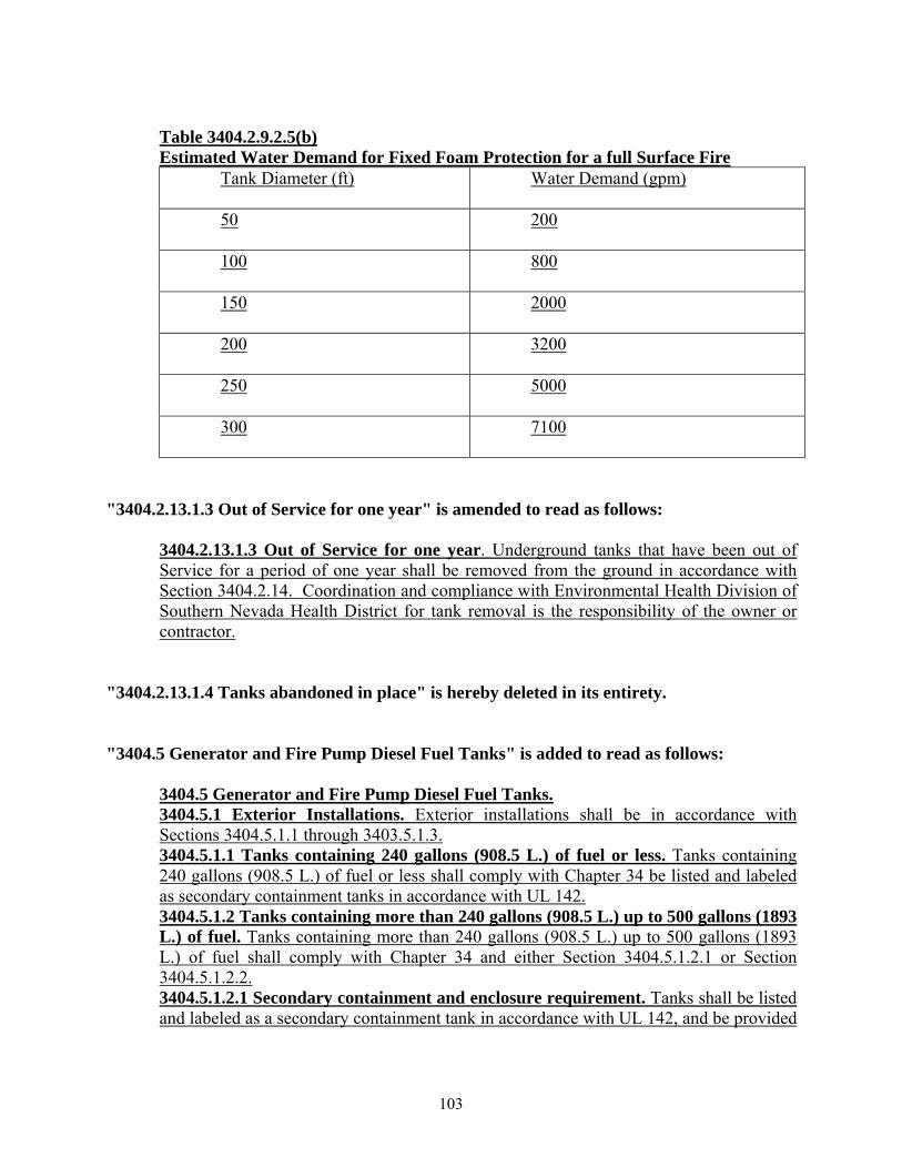
Table 3404.2.9.2.5(b) Estimated Water Demand for Fixed Foam Protection for a full Surface Fire
Tank Diameter (ft) Water Demand (gpm)
50 200
100 800
150 2000
200 3200
250 5000
300 7100
"3404.2.13.1.3 Out of Service for one year" is amended to read as follows:
3404.2.13.1.3 Out of Service for one year. Underground tanks that have been out of Service for a period of one year shall be removed from the ground in accordance with Section 3404.2.14. Coordination and compliance with Environmental Health Division of Southern Nevada Health District for tank removal is the responsibility of the owner or contractor.
"3404.2.13.1.4 Tanks abandoned in place" is hereby deleted in its entirety. "3404.5 Generator and Fire Pump Diesel Fuel Tanks" is added to read as follows:
3404.5 Generator and Fire Pump Diesel Fuel Tanks. 3404.5.1 Exterior Installations. Exterior installations shall be in accordance with Sections 3404.5.1.1 through 3403.5.1.3. 3404.5.1.1 Tanks containing 240 gallons (908.5 L.) of fuel or less. Tanks containing 240 gallons (908.5 L.) of fuel or less shall comply with Chapter 34 be listed and labeled as secondary containment tanks in accordance with UL 142. 3404.5.1.2 Tanks containing more than 240 gallons (908.5 L.) up to 500 gallons (1893 L.) of fuel. Tanks containing more than 240 gallons (908.5 L.) up to 500 gallons (1893 L.) of fuel shall comply with Chapter 34 and either Section 3404.5.1.2.1 or Section 3404.5.1.2.2. 3404.5.1.2.1 Secondary containment and enclosure requirement. Tanks shall be listed and labeled as a secondary containment tank in accordance with UL 142, and be provided
103
with an approved protective enclosure complying with Sections 3404.5.1.2.1.1 and 3404.5.1.2.1.2. 3404.5.1.2.1.1 Protective enclosure construction. When approved by the fire code official, the methods described in this section are acceptable as bullet-resistant construction. The steel and wood dimensions indicated are actual thicknesses. Concrete block and brick dimensions indicated are the manufacturer’s represented thicknesses. The height of the protective enclosure shall be a minimum of 18 inches above the height of the tank.
1. Exterior of 5/8-inch (15.9 mm) steel, lined with an interior of any type of nonsparking material.
2. Exterior of 1/2-inch (12.7 mm) steel, lined with an interior of not less than 3/8-inch (9.5 mm) plywood.
3. Exterior of 3/8-inch (9.5 mm) steel, lined with an interior of 2 inches (50.8 mm) or hardwood.
4. Exterior of 3/8-inch (9.5 mm) steel, lined with an interior of 3 inches (76.2 mm) of softwood or 21/4 inches (57.2 mm) of plywood
5. Exterior of 1/4-inch (6.4 mm) steel, lined with an interior of 3 inches (76.2 mm) of hardwood
6. Exterior of 1/4-inch (6.4 mm) steel, lined with an interior of 5 inches (127 mm) of softwood or 51/4 inches (133.4 mm) of plywood
7. Exterior of 1/4-inch (6.4 mm) steel, lined with an intermediate layer of 2 inches (50.8 mm) of hardwood and an interior lining of 11/2 inches (38.1 mm) of plywood
8. Exterior of 3/16-inch (4.8 mm) steel, lined with an interior of 4 inches (101.6 mm) of hardwood
9. Exterior of 3/16-inch (4.8 mm) steel, lined with an interior of 7 inches (177.8 mm) of softwood or 63/4 inches (171.4 mm) of plywood
10. Exterior of 3/16-inch (4.8 mm) steel, lined with an intermediate layer of 3 inches (76.2 mm) of hardwood and an interior lining of 3/4-inch (19.1 mm) of plywood
11. Exterior of 1/8-inch (3.2 mm) steel, lined with an interior of 5 inches (127 mm) of hardwood
12. Exterior of 1/8-inch (3.2 mm) steel, lined with an interior of 9 inches (228.6 mm) of softwood
13. Exterior of 1/8-inch (3.2 mm) steel, lined with an intermediate layer of 4 inches (101.6 mm) of hardwood and an interior lining of 3/4-inch (19.1 mm) plywood
14. Exterior of any type of fire-resistant material which is structurally sound, lined with an intermediate layer of 4 inches (101.6 mm) of solid concrete block or 4 inches (101.6 mm) of solid brick or 4 inches (101.6 mm) of solid concrete, and an interior lining of 1/2-inch (12.7 mm) plywood placed securely against the masonry lining
15. Standard 8-inch (203.2 mm) concrete block with voids filled with a well-tamped sand/cement mixture
16. Standard 8-inch (203.2 mm) solid brick
104
17. Exterior of any type of fire-resistant material which is structurally sound, lined with an intermediate 6-inch (152.4 mm) space filled with well-tamped dry sand or a well-tamped sand/cement mixture
18. Exterior of 1/8-inch (3.2 mm) steel, lined with a first intermediate layer of 3/4-inch (19.1 mm) plywood, a second intermediate layer of 35/8 inches (92.1 mm) of a well-tamped dry sand or sand/cement mixture and an interior lining of 3/4-inch (19.1 mm) plywood
19. Exterior of any type of fire-resistant material, lined with a first intermediate layer of 3/4-inch (19.1 mm) plywood, a second intermediate layer of 35/8 inches (92.1 mm) of a well-tamped dry sand or sand/cement mixture, a third intermediate layer of 3/4-inch (19.1 mm) plywood, and a fourth intermediate layer of 2 inches (50.8 mm) of hardwood or not less than 0.068 inch (1.7 mm) of steel and an interior lining of 3/4-inch (19.1 mm) plywood
20. Eight-inch-thick (203.2 mm) solid concrete 3404.5.1.2.1.2 Protective enclosure doors. Doors shall be bullet resistant as specified in Section 3404.5.1.2.1.1. Hinges and hasps shall be attached to the doors by welding, riveting, or bolting with nuts on the inside of the door. Hinges and hasps shall be installed in such a manner that they cannot be removed when the doors are closed and locked. Exception: Doors not facing the public way. 3404.5.1.2.2. Protected secondary containment tanks. Tanks shall be listed and labeled as 2 hour protected secondary containment tanks in accordance with UL 2085. 3404.5.1.3 Tanks containing more than 500 gallons (1893 L.) of fuel. Tanks containing more than 500 gallons (1893 L.) of fuel shall comply with Chapter 34 and shall be listed and labeled as 2 hour protected secondary containment tanks in accordance with UL 2085. 3404.5.1.4 Separation distances. A protected aboveground tank shall be separated from property lines, important buildings, public ways, and other tanks in accordance with 2008 NFPA 30 Section 22.4. 3404.5.2 Interior Installations. Interior installations of aboveground fuel tanks shall comply with Chapters 27 and 34.
"3406.2.4.4 Locations where above-ground tanks are prohibited" is amended to read as follows:
3406.2.4.4 Locations where above-ground tanks are prohibited. The storage of class I, II, and III liquids in above-ground tanks outside of buildings is prohibited.
Exception: When approved by the planning or zoning authority (in jurisdictions requiring this specific approval) and when approved by the fire code official.
"3406.5.1.6 Fire protection" is amended to read as follows:
3406.5.1.6 Fire Protection. Fire Protection shall be in accordance with Section 3403.2. Where operations involve vehicle loading of Class 1 and/or Class 2 liquids, the loading areas shall be protected with approved automatic fire protection systems.
105
"3406.5.4.5 Commercial, industrial, governmental or manufacturing" is amended to read as follows:
3406.5.4.5 Commercial, industrial, governmental or manufacturing. Dispensing of motor vehicle fuel from tank vehicles into the fuel tanks of motor vehicles located at commercial, industrial, governmental or manufacturing establishments is allowed where permitted, provided such dispensing operations are conducted in accordance with the following:
"3406.5.4.5 (1)" is amended to read as follows:
1. Dispensing shall occur only out of mobile fueling vehicles that have been issued a permit to dispense fuel and only at sites that have been issued a permit to conduct mobile fueling.
IFC CHAPTER 35 "3506.2 Limitations" is amended to read as follows:
3506.2 Limitations. Storage of flammable cryogenic fluids in stationary containers outside of buildings is prohibited.
Exception: When approved by the planning or zoning authority (in jurisdictions requiring this specific approval) and when approved by the fire code official.
IFC CHAPTER 38 "3804.2 Liquefied petroleum gas storage containers" is amended to read as follows:
3804.2 Liquefied petroleum gas storage containers. The storage of liquefied petroleum gas is prohibited.
Exception: When approved by the planning or zoning authority (in jurisdictions requiring this specific approval) and when approved by the fire code official.
IFC CHAPTER 46 "4601.1 Scope” is amended to read as follows:
106

4601.1 Scope. The provisions of this chapter shall apply to existing buildings constructed prior to adoption of this code.
Exception: Retroactive provisions contained within this code that are more stringent than retroactive provisions adopted by the State Fire Marshal shall not be enforceable until approval for such enforcement is obtained from the State Board of Examiners in accordance with NRS 477.110.
"4601.4.2 Completion of work” is amended to read as follows:
4601.4.2 Completion of work. Work on the required alterations to the building shall be completed within a time schedule approved by the fire code official. Where a retrofit installation is required by this code, timelines for installation and completion shall be negotiated between the building owner and the fire code official
"4601.5 New work in existing buildings" is added to read as follows:
4601.5 New work in existing buildings. Where new work occurs in an existing building or facility, such work shall be in accordance with current code, and fire protection systems impacted in the work area shall be upgraded to current code requirements commensurate with the overall scope of new work.
Exception: Replacement of finishes, furnishings, plumbing fixtures, electrical fixtures, and equipment, which does not increase the fire hazard, shall not require upgrade of fire protection systems.
IFC CHAPTER 47 "NFPA 13-10" is amended to read as follows:
13-10 Installation of Sprinkler Systems……………………….Table 903.1.1, 903.3.2, 903.3.5.1.1, 903.3.5.2, 904.11, 905.3.4, 907.7.3, 2301.1, 2304.2, Table 2306.2, 2306.9, 2307.2, 2307.2.1, 2308.2.2, 2308.2.2.1, 2308.4, 2310.1, 2501.1, 2804.1, 2806.5.7, 3404.3.3.9, Table 3404.3.6.3(7), 3404.3.7.5.1, 3404.3.8.4
"NFPA 13D-10" is amended to read as follows:
13D-10 Installation of Sprinkler Systems in One- and Two-family Dwellings and Manufactured Homes ……………………….903.3.1.3, 903.3.5.1.1
"NFPA 13R-10" is amended to read as follows:
107
13R-10 Installation of Sprinkler Systems in Residential Occupancies up to and Including Four Stories in Height ……………………….903.3.1.2, 903.3.5.1.1, 903.3.5.1.2, 903.4
"NFPA 14-10" is amended to read as follows:
14-10 Installation of Standpipe and Hose Systems ……………………….905.2, 905.3.4, 905.4.2, 905.6.2, 905.8
"NFPA 20-10" is amended to read as follows:
20-10 Installation of Stationary Pumps for Fire Protection ……………….913.1, 913.2, 913.5.1
"NFPA 22-08" is amended to read as follows:
22-08 Water Tanks for Private Fire Protection……………………….507.2.2 "NFPA 54-06" is added to read as follows:
54-06 National Fuel Gas Code "NFPA 72-10" is amended to read as follows:
72-10 National Fire Alarm Code ……………………….508.1.5, Table 901.6.1, 903.4.1, 904.3.5, 907.2, 907.2.6, 907.2.11, 907.2.13.2, 907.3, 907.4.3, 907.4.4, 907.6.2.1.2, 907.6.2.2, 907.7, 907.7.1, 907.7.2, 907.7.5, 907.8, 907.8.1, 907.8.2, 907.9, 907.9.2, 907.9.5, I101.1, J103.1.4
"4701 Modified NFPA Standards" is added to read as follows:
4701 Modified NFPA Standards. Standards promulgated by the National Fire Protection Association (NFPA) and modified herein are hereby adopted by reference. NFPA standards are available from the National Fire Protection Association, 1 Batterymarch Park, P.O. Box 9101, Quincy, Massachusetts, 02269-9101.
“4701.1 NFPA 10, Standard for Portable Fire Extinguishers”, is added to read as follows:
108

4701.1 NFPA 10, Standard for Portable Fire Extinguishers. NFPA 10-2007 is available from the National Fire Protection Association, 1 Batterymarch Park, P.O. Box 9101, Quincy, Massachusetts, 02269-9101. The National Fire Protection Association Standard for Portable Fire Extinguishers is hereby adopted by reference with the following modifications:
Section 6.1.3.2 of NFPA 10 is amended to read as follows:
6.1.3.2 Fire extinguishers shall be located along normal paths of travel, including exits from areas, unless the fire code official determines that the hazard posed indicates the need for placement away from normal paths of travel.
Section 6.1.3.10.1 of NFPA 10 is amended to read as follows:
6.1.3.10.1 Cabinets housing fire extinguishers shall not be locked. Exceptions: 1. Where portable fire extinguishers subject to malicious use or damage are
provided with a means of ready access. 2. In Group I-3 occupancies and in mental health areas in Group I-2
occupancies, access to portable fire extinguishers shall be permitted to be locked or to be located in staff locations provided the staff has keys.
Section 6.2.1.3.1.1 of NFPA 10 is amended to read as follows:
6.2.1.3.1.1 Up to two water-type extinguishers, each with 1-A rating, shall be permitted to be used to fulfill the requirements of one 2-A rated extinguisher for light (low hazard) occupancies only.
Section 6.6.3 of NFPA 10 is amended to read as follows:
6.6.3 All solid fuel cooking appliances (whether or not under a hood) with fire boxes of 5 ft3 (0.14 m3) volume or less shall have a minimum 2.5 gallon (9 L) or two 1.5 gallon (6 L) Class K wet-chemical portable fire extinguishers located in accordance with the IFC Section 904.11.5.
Section 6.6.4 of NFPA 10 is amended to read as follows:
6.6.4 When hazard areas include deep fat fryers, listed Class K portable fire extinguishers shall be provided as follows: (1) For up to four fryers having a maximum cooking medium capacity of 80 pounds
(36.3 kg) each: One Class K portable fire extinguisher of a minimum 1.5 gallon (6 L) capacity.
(2) For every additional group of four fryers having a maximum cooking medium capacity of 80 pounds (36.3 kg) each: One additional Class K portable fire extinguisher of a minimum 1.5 gallon (6 L) capacity shall be provided.
109
(3) For individual fryers exceeding 6 square feet (0.55 m2) in surface area: Class K portable fire extinguishers shall be installed in accordance with the extinguisher manufacturer’s recommendations.
“4701.2 NFPA 13, Standard for the Installation of Fire Sprinklers” is added to read as follows:
4701.2 NFPA 13, Standard for the Installation of Fire Sprinklers. NFPA 13-2010 is available from the National Fire Protection Association, 1 Batterymarch Park, P.O. Box 9101, Quincy, Massachusetts, 02269-9101. The National Fire Protection Association Standard for the Installation of Fire Sprinklers is hereby adopted by reference with the following modifications:
Section 5.3.2 of NFPA 13 is amended to read as follows:
5.3.2 Ordinary Hazard (Group 2) Ordinary hazard (Group 2) occupancies shall be occupancies or portions of other occupancies where the quantity and combustibility of contents is moderate to high, stockpiles do not exceed 12 ft (3.7 m), and fires with moderate to high rates of heat release are expected. Occupancies containing Casinos, Mini-Storage Facilities, and Shell Buildings, regardless of occupancy classification (unknown tenants and/or floor layout), shall be designed to meet the requirements of Ordinary Hazard Group 2.
Section 6.1.3 of NFPA 13 is amended to read as follows:
6.1.3 Rated Pressure. System components shall be rated for the maximum system working pressure to which they are exposed but shall not be rated at less than 175 psi (12.1 bar) for components installed aboveground and 150 psi (10.4 bar) for components installed underground. When the underground piping can be supplied or pressurized by a Fire Department Connection (FDC), the underground piping shall be designed to withstand a working pressure of not less than 200 psi (Class 200), or 50 psi greater than the system design pressure, whichever is greater.
Section 6.2.9.7.1 of NFPA 13 is amended to read as follows:
6.2.9.7.1 The list shall be on a machine-engraved metal or rigid plastic sign with capitalized lettering a minimum 14 point (¼ inch high) in Arial or similar font and include the following: (1) Sprinkler Identification Number (SIN) if equipped; or the manufacturer, model, orifice, deflector type, thermal sensitivity, and pressure rating. (2) General description. (3) Quantity of each type to be contained in the cabinet. (4) Issue or revision date of the list.
Section 6.3.1.1.1 of NFPA 13 is added to read as follows:
110
6.3.1.1.1 Pipe or tube shall have a minimum Corrosion Resistant Ratio (CRR) of 1.
Section 6.8.1.4 of NFPA 13 is added to read as follows:
6.8.1.4 The minimum number of required inlets shall be one 2 ½ inch inlet for every 250 gpm of the sprinkler and/or standpipe demand, or fraction there of. Fire Department Connections (FDC) shall be provided with internal check valve(s) such that water being supplied into any inlet will not flow back out of any other inlet. For the purposes of this section, internal clapper valve devices provided by the manufacturer in listed FDC shall be considered internal check valves.
Section 6.9.1 of NFPA 13 is amended to read as follows: 6.9.1 Waterflow alarm devices shall be listed for the service and so constructed and installed that any flow of water from a sprinkler system equal to or greater than that from a single automatic sprinkler of the smallest orifice installed on the system will result in an audible alarm on the premises within 60 seconds after such flow begins and until such flow stops.
Section 6.9.1.1 of NFPA 13 is added to read as follows: 6.9.1.1 Multi-story buildings shall have water flow alarm annunciation on a floor by floor basis.
Section 6.9.1.2 of NFPA 13 is added to read as follows: 6.9.1.2 Sprinkler systems, such as those protecting atriums, covered mall buildings, and other areas with non-standard ceiling heights within the building, shall be designed such that system water flow annunciation indicates the protected floor level, rather than the floor level where the system piping occurs.
Section 6.9.3.1 of NFPA 13 is amended to read as follows: 6.9.3.1 Alarm Unit(s). Alarm unit(s) shall be a horn/strobe device listed for fire alarm signaling.
Section 6.9.3.2 of NFPA 13 is amended to read as follows:
6.9.3.2 Exterior Alarm Unit(s). Exterior alarm unit(s) shall be weatherproofed.
Section 6.9.3.3 of NFPA 13 is amended to read as follows: 6.9.3.3 Exterior Alarm Unit. There shall be a minimum of one exterior horn/strobe alarm unit provided on the exterior wall above the Fire Department Connection.
111

Section 6.9.3.4 of NFPA 13 is amended to read as follows:
6.9.3.4. Number of Interior Alarm Unit(s). There shall be a minimum of one interior horn/strobe alarm unit provided in a normally occupied location. In multi-tenant buildings, there shall be one interior alarm unit in each tenant space. All interior alarm units associated with a single sprinkler system shall activate simultaneously upon activation of that fire sprinkler system.
Section 6.9.3.5 of NFPA 13 is added to read as follows:
6.9.3.5 Interior alarm units are not required when the building is protected throughout with a fire alarm system in accordance with adopted codes and the fire alarm system will activate upon actuation of any sprinkler system within the building
Section 7.1.3 of NFPA 13 is amended to read as follows:
7.1.3 A wet pipe system shall be permitted to supply an auxiliary antifreeze, dry pipe, or preaction system provided the auxiliary system covers less than 10% of the system size.
Section 7.2.3.1 of NFPA 13 is amended to read as follows:
7.2.3.1 The system capacity (volume) controlled by a dry pipe valve shall be determined by 7.2.3.2, or 7.2.3.5.
Section A.7.2.3.1 of NFPA 13 is hereby deleted in its entirety. Section 7.2.3.3 of NFPA 13 is hereby deleted in its entirety. Section 7.2.3.4 of NFPA 13 is hereby deleted in its entirety. Section 7.2.3.5 of NFPA 13 is amended to read as follows:
7.2.3.5 System size shall be based on dry systems being calculated for water delivery in accordance with 7.2.3.6. Testing of the system shall be accomplished by the methods indicated in 7.2.3.7.
Section 7.2.7 of NFPA 13 is added to read as follows: 7.2.7 Application of Dry-Pipe Systems. Dry pipe systems shall not be utilized for the protection of areas that can be maintained above 40 degrees.
Exception: When permitted by the fire code official, dry sprinklers may be installed in small conditioned rooms within buildings that otherwise require dry sprinkler systems throughout.
Section 7.3.2.3.1.2 of NFPA 13 is amended to read as follows:
112

7.3.2.3.1.2 The system size for double interlock preaction systems shall be based on calculating water delivery in accordance with 7.2.3.6, anticipating that the detection system activation and sprinkler operation will be simultaneous. Testing of the system shall be accomplished by the methods indicated in 7.2.3.7.
Section 7.6.2.4 of NFPA 13 is amended to read as follows:
7.6.2.4 An antifreeze solution shall be prepared with a freezing point at or below 0º F (-17.8º C)
Section 7.6.2.4.1 of NFPA 13 is added to read as follows: 7.6.2.4.1 Where the antifreeze system is intended to be installed at an elevation where temperatures below 0º F (-17.8º C) are expected, the system shall be prepared with a freezing point below the minimum expected temperature for the area.
Section 7.10.2.2 of NFPA 13 is hereby deleted in its entirety. Section 7.10.2.6 of NFPA 13 is added to read as follows:
7.10.2.6 Sprinklers protecting cooking exhaust ducts shall be supplied from dedicated supply risers separate from overhead sprinkler systems. Activation of the associated water flow switch shall shut down the fuel and/or electrical power supply to the associated cooking equipment and the makeup air supplied internally to the hood.
Section 7.10.3.1 of NFPA 13 is amended to read as follows: 7.10.3.1 Unless the requirements of 7.10.3.2 or 7.10.3.4 are met, exhaust ducts shall have one sprinkler or automatic spray nozzle located at the top of each vertical riser, at the midpoint of each offset, and an additional sprinkler shall be installed within the duct at 20-foot intervals on vertical risers where not otherwise provided with sprinklers due to offsets in buildings over two stories.
Section 8.2.4 of NFPA 13 is amended to read as follows: 8.2.4 When acceptable to the authority having jurisdiction, multiple buildings that are assigned the same street address, without independent building numbers, and are attached by canopies, covered breezeways, common roofs, or a common wall(s) shall be permitted to be supplied by a single fire sprinkler riser. The maximum system size shall comply with 8.2.1
Section 8.2.6 of NFPA 13 is added to read as follows: 8.2.6 In multi-story buildings, each story requires a separate system with control valve and water flow switch.
113
Section 8.2.7 of NFPA 13 is added to read as follows: 8.2.7 For tenant spaces adjacent to and having public access exclusively through an adjacent assembly space, such as tenant spaces adjacent to casinos, covered mall buildings, and other assembly spaces, the tenant spaces shall be provided with individual isolation control valves. For the purposes of this section, the isolation control valve does not define a separate sprinkler system, such that the overall size of the sprinkler system serving the tenant space(s) and adjacent spaces must meet size limitations of 8.2.1 when measured from the control valve located on the system riser.
Section 8.3.3.1 of NFPA 13 is amended to read as follows: 8.3.3.1 Sprinklers in light hazard occupancies, shell buildings of combustible construction, casinos, and exhibition areas shall be one of the following: (1) Quick-response type as defined in 3.6.2.9 (2) Residential sprinklers in accordance with the requirements of 8.4.5 (3) Standard response sprinklers used for modifications or additions, within the existing
compartment, to existing systems equipped with standard response sprinklers (4) Standard response sprinklers used where individual standard response sprinklers are
replaced in existing systems
Section 8.6.4.1.1.3 of NFPA 13 is amended to read as follows: 8.6.4.1.1.3 The requirements of 8.6.4.1.1.1 shall not apply for light and ordinary hazard occupancies with ceilings of noncombustible construction, as follows: (A) Where there is a vertical change in ceiling elevation within the area of coverage of the sprinkler creates a distance of more than 36 in. (914 mm) between the upper ceiling and the sprinkler deflector, a vertical plane extending down from the ceiling at the change in elevation shall be considered a wall for the purpose of sprinkler spacing as shown in Figure 8.6.4.1.1.3(A). (B) Where the distance between the upper ceiling and the sprinkler deflector is less than or equal to 36 in. (914 mm), the sprinklers shall be permitted to be spaced as though the ceiling was flat, provided the obstruction rules are observed as shown in Figure 8.6.4.1.1.3(B).
Section 8.8.4.1.1.4 of NFPA 13 is amended to read as follows: 8.8.4.1.1.4 The requirements of 8.8.4.1.1.1 shall not apply for light and ordinary hazard occupancies with ceilings of noncombustible construction, as follows. (A) Where there is a vertical change in ceiling elevation within the area of coverage of the sprinkler creates a distance of more than 36 in. (914 mm) between the upper ceiling and the sprinkler deflector, a vertical plane extending down from the ceiling at the change in elevation shall be considered a wall for the purpose of sprinkler spacing. (B) Where the distance between the upper ceiling and the sprinkler deflector is less than or equal to 36 in. (914 mm), the sprinklers shall be permitted to be spaced as though the ceiling was flat, provided the obstruction rules and ceiling pocket rules are observed.
114

Section 8.14.6 of NFPA 13 is amended to read as follows:
8.14.6 Pilot line detectors shall be permitted to be spaced more than 22 in. (559 mm) below a ceiling or deck where the maximum spacing between pilot line detectors is 10 ft (3 m) or less, and where such spacing is supported by an engineering analysis discussing sprinkler temperature and response rating, plume diameter, temperature within the plume that will pass across the sprinklers, and the expected fire size required to activate the pilot sprinklers.
Section 8.15.1.2.1 of NFPA 13 is amended to read as follows: 8.15.1.2.1 Concealed spaces of noncombustible construction with minimal combustible loading having no access shall not require sprinkler protection. The space shall be considered a concealed space even with small openings such as those used as return air for a plenum. For purposes of this section, “construction” is limited to wall assemblies, floor assemblies, ceiling assemblies, and structural members.
Section 8.15.1.2.1.2 of NFPA 13 is added to read as follows: 8.15.1.2.1.2 Minor quantities of combustible materials limited to: cabling, nonmetallic piping conveying non-combustible liquids, and nonmetallic HVAC ductwork as expressly allowed by applicable building codes, shall be permitted in concealed spaces constructed of non-combustible materials but shall not require sprinklers.
Section 8.15.1.2.2 of NFPA 13 is amended to read as follows: 8.15.1.2.2 Concealed spaces of non-combustible construction with limited access and minimal combustible loading and not permitting occupancy or storage of combustibles shall not require sprinkler protection. The space shall be considered a concealed space even with small openings such as those used as return air for a plenum. For the purposes of this section, limited access does not include access to catwalks and mechanical mezzanines. Catwalks and mechanical mezzanines shall be allowed to be provided with sprinkler protection in accordance with 8.15.1.5. Additionally, “construction” is limited to wall assemblies, floor assemblies, ceiling assemblies, and structural members.
Section 8.15.1.2.10 of NFPA 13 is hereby deleted in its entirety.
Section 8.15.1.2.11 of NFPA 13 is hereby deleted in its entirety.
Section 8.15.1.2.16 of NFPA 13 is amended to read as follows: 8.15.1.2.16 Concealed spaces formed by noncombustible ceilings suspended from the bottom of wood joists, composite wood joists, wood bar joists, or wood trusses that have insulation filling all of the gaps between the bottom of the trusses or joists, and where sprinklers are present in the space above the installation within the trusses or joists, shall not require sprinklers.
115

Section 8.15.1.2.17 of NFPA 13 is amended to read as follows: 8.15.1.2.17 Concealed spaces formed by noncombustible ceilings suspended from the bottom of wood joists and composite wood joists with a maximum nominal chord width of 2 in. (50.8 mm), where joist spaces are full of noncombustible batt insulation with a maximum 2 in. (590.8 mm)air space between the roof decking material and the top of the batt insulation. Facing that meets the requirements for noncombustible material covering the surface of the bottom chord of each joist and secured in place per the manufacturer’s recommendations shall not require sprinklers.
Section 8.15.4.1 of NFPA 13 is amended to read as follows: 8.15.4.1 General. Unless the requirements of 8.15.4.4 are met, where moving stairways, staircases, or similar floor openings are unenclosed and where sprinkler protection is serving as the alternate to enclosure of the vertical opening, the floor openings involved shall be protected by closely spaced sprinklers supplied by a dedicated sprinkler riser in combination with draft stops in accordance with 8.15.4.2 and 8.15.4.3
Section 8.15.5.1 of NFPA 13 is amended to read as follows: 8.15.5.1 Sidewall spray sprinklers shall be installed at the bottom of each elevator hoistway not more than 2 ft (0.61 m) above the floor of the pit. Sprinklers are prohibited at the top of the hoistway and in the machine room, unless otherwise approved by the Authority Having Jurisdiction.
Section 8.15.5.2 of NFPA 13 is hereby deleted in its entirety.
Section 8.15.5.3 of NFPA 13 is hereby deleted in its entirety.
Section 8.15.5.4 of NFPA 13 is hereby deleted in its entirety.
Section 8.15.5.5 of NFPA 13 is hereby deleted in its entirety.
Section 8.15.5.6 of NFPA 13 is hereby deleted in its entirety.
Section 8.15.7.1 of NFPA 13 is amended to read as follows: 8.15.7.1 Unless the requirements of 8.15.7.2 or 8.15.7.4 are met, sprinklers shall be installed under exterior roofs, canopies, or porte-cocheres exceeding 4 ft (1.2 m) in width.
Section 8.15.7.2 of NFPA 13 is amended to read as follows:
116
8.15.7.2 Sprinklers shall be permitted to be omitted where the canopies, roofs, porte-cocheres, balconies, decks, or similar projections are constructed entirely with materials that are noncombustible and where the canopies, roofs, porte-cocheres, balconies, decks, or similar protections do not support occupancy above.
Section 8.15.7.3 of NFPA 13 is hereby deleted in its entirety.
Section 8.15.8.1.1 of NFPA 13 is amended to read as follows: 8.15.8.1.1 Sprinkler protection shall be provided in all bathrooms.
Section 8.15.8.1.1.1 of NFPA 13 is added to read as follows: 8.15.8.1.1.1 Sprinkler protection shall not be required in separate rooms that contain solely a toilet fixture, that contain no counters, shelving, closet doors, or other fixtures, and that have a maximum area of 55 ft2 (5.1 m2). Such rooms shall be surrounded by walls and doors that completely enclose the room.
Section 8.15.8.2 of NFPA 13 is amended to read as follows: 8.15.8.2 Closets and Pantries. Sprinklers shall be provided in clothes closets, linen closets, and pantries.
Section 8.15.10.1 of NFPA 13 is amended to read as follows: 8.15.10.1 Sprinkler protection shall be required in electrical equipment rooms.
Section 8.15.10.3 of NFPA 13 is hereby deleted in its entirety.
Section 8.15.4.1 of NFPA 13 is amended to read as follows: 8.15.14.1 Drop-out ceilings are not permitted to be installed beneath fire sprinklers.
Section 8.15.14.2 of NFPA 13 is hereby deleted in its entirety.
Section 8.15.14.3 of NFPA 13 is hereby deleted in its entirety.
Section 8.15.14.4 of NFPA 13 is hereby deleted in its entirety.
Section 8.15.19.1.1 of NFPA 13 is added to read as follows: 8.15.19.1.1 Unless hydraulically calculated, each one-inch outlet shall supply a maximum of one sprinkler head providing protection below a ceiling, and if necessary, a maximum of one head above the ceiling. Such sprinkler head(s) shall have a k-factor equal to the k-factor of existing upright sprinklers.
117
Section 8.15.19.1.2 of NFPA 13 is added to read as follows: 8.15.19.1.2 Unless otherwise hydraulically calculated, a one-inch outlet shall be allowed to supply a maximum of two sprinkler heads where the two sprinkler heads protect areas that are physically separated by a ceiling, walls and/or doors with a minimum lintel depth of 8 in (203 mm) and maximum total area of door openings into the room of 50 ft2 (4.6 m2). The sprinklers shall have a k-factor equal to the k-factor of existing upright sprinklers.
Section 8.15.19.1.3 of NFPA 13 is added to read as follows: 8.15.19.1.3 When approved sprinkler heads installed under a ceiling may have a k factor less than the overhead sprinklers, provided the occupancy hazard classification for the area under the ceiling is less than the classification that the overhead sprinklers are designed for.
Section 8.15.19.1.4 of NFPA 13 is added to read as follows: 8.15.19.1.4 Flexible sprinkler hose drops shall be proven by hydraulic calculations.
Section 8.15.22.3 of NFPA 13 is amended to read as follows: 8.15.22.3 Where there is a noncombustible space above a noncombustible drop ceilings that is sprinklered because it is open to an adjacent sprinklered space on only one side and where there is no possibility for storage above the drop ceiling, the sprinkler system shall be permitted to extend only as far into the space as 0.6 times the square root of the design area of the sprinkler system in the adjacent space.
Section 8.15.23 of NFPA 13 is added to read as follows: 8.15.23 Openings in Rated Assemblies. Where sprinkler protection is serving as the alternative to opening protection in rated assemblies, such sprinklers shall be listed for use, and installed in accordance with their listing. These sprinklers shall be a separate sprinkler system, and shall be controlled, monitored, and supplied independently of the overhead system(s).
Section 8.16.1.1.1.4 of NFPA 13 is added to read as follows: 8.16.1.1.1.4 Valve rooms shall be lighted and heated.
Section 8.16.1.1.1.5 of NFPA 13 is added to read as follows: 8.16.1.1.1.5 The source of heat shall be of a permanently installed type.
Section 8.16.1.1.1.6 of NFPA 13 is added to read as follows:
118
8.16.1.1.1.6 Heat tape shall not be used in lieu of heated valve enclosures to protect the valve and supply pipe against freezing.
Section 8.16.1.1.2.1 of NFPA 13 is amended to read as follows: 8.16.1.1.2.1 Valves on connections to water supplies, sectional control and isolation valves, and other valves in supply pipes to sprinkler and other fixed water-based fire suppression systems shall be electrically supervised by a central station, proprietary, or remote station signaling service.
Section 8.16.1.1.2.3 of NFPA 13 is amended to read as follows: 8.16.1.1.2.3 The requirements of 8.16.1.1.2.1 shall not apply to underground gate valves with roadway boxes or to valves at backflow prevention devices at the municipal water supply connection where the valves are locked in the open position.
Section 8.16.1.2.5 of NFPA 13 is amended to read as follows: 8.16.1.2.5 Means shall be provided downstream of all pressure-reducing valves for flow tests at sprinkler system demand. Such means shall consist of a tee outlet downstream of the pressure-reducing valve identical in size to the sprinkler system feed, available for connection to field testing devices, or another method approved by the AHJ.
Section 8.16.4.1.6 of NFPA 13 is added to read as follows: 8.16.4.1.6 Design Temperature and Duration. The minimum criteria for an engineered solution in calculating heat loss for the requirement to maintain 40ºF (4.4ºC) shall be 0º F (-17.8ºC) for 8 hours. The initial starting temperature of the water shall be no greater than 50ºF (10ºC).
Section 8.17.1.1 of NFPA 13 is amended to read as follows: 8.17.1.1. Local Waterflow Alarm Units. A local waterflow alarm unit shall be provided on every sprinkler system. Such waterflow alarm units shall be installed in accordance with 6.9.
Section 8.17.2.3 of NFPA 13 is amended to read as follows: 8.17.2.3 Size. The size of the pipe for the fire department connection shall be in accordance with one of the following: (1) Pipe size shall be a minimum of 4 in. (100 mm) for fire engine connections when the
fire department connection has three or fewer 2-1/2 in (65 mm) inlets, and shall be a minimum of 6 in. (150 mm) for fire engine connections when the fire department connection has four or more 2-1/2 in (65 mm) inlets.
(2) Pipe size shall be a minimum of 6 in. (150 mm) for fire boat connections.
119

(3) For hydraulically calculated systems the fire department connection shall be permitted to be less than 4 in. (100 mm) and no less than the size of system riser, where serving one system riser.
Section 8.17.2.7 of NFPA 13 is added to read as follows:
8.17.2.7 The fire department connection shall be located not less than 18 in (457 mm) and not more than 4 ft (1.2 m) above the level of the adjacent grade or access level.
Section 9.1.3.9.3 of NFPA 13 is amended to read as follows: 9.1.3.9.3 Powder-driven fasteners shall be allowed for branch lines less than or equal to 2 in. (50 mm) pipe.
Section 9.1.3.9.4 of NFPA 13 is amended to read as follows: 9.1.3.9.4 Increaser couplings shall not be permitted with powder-driven studs.
Section 9.2.1.3.3.4 of NFPA 13 is added to read as follows: 9.2.1.3.3.4 Where flexible sprinkler hose fittings are supported by a ceiling that does not meet design and installation criteria set forth in 9.2.1.3.3.2, such fitting shall be provided with hangers in accordance with 9.2.3.5, unless the flexible hose fitting is provided with a hanger assembly specifically approved by a Nationally Recognized Testing Laboratory for both the flexible sprinkler hose fitting and the specific method of installation.
Section 9.3.5.6.2 of NFPA 13 is amended to read as follows: 9.3.5.6.2 The horizontal force, Fpw, acting on the brace shall be taken as Fpw = CpWp, where Cp is the seismic coefficient selected in Table 9.3.5.6.2 utilizing the short period response parameter Ss. The value of Ss used in Table 9.3.5.6.2 shall be 0.95 or derived from seismic hazard data from the U.S. Geological Survey using ASCE Standard 7, 2005 edition. Linear interpolation shall be permitted to be used for intermediate values of Ss.
Section 10.1.5 of NFPA 13 is amended to read as follows: 10.1.5 Working Pressure. Pipe shall be designed to withstand a system working pressure of not less than 150 psi (10.3 bar). When the underground piping can be supplied or pressurized by a Fire Department Connection (FDC), the underground piping shall be designed to withstand a working pressure of not less than 200 psi (Class 200), or 50 psi greater than the FDC design pressure, whichever is greater.
Section 11.2.3.1.4(4)(a) of NFPA 13 is amended to read as follows:
120
11.2.3.1.4(4)(a) Noncombustible concealed spaces with minimal combustible loading having no access. The space shall be considered a concealed space even with small openings such as those used as return air for a plenum.
Section 11.2.3.1.4(4)(b) of NFPA 13 is amended to read as follows: 11.2.3.1.4(4)(b) Noncombustible concealed spaces with limited access and not permitting occupancy or storage of combustibles. The space shall be considered a concealed space even with small openings such as those used as return air for a plenum.
Section 11.2.3.1.4(4)(d) of NFPA 13 is amended to read as follows: 11.2.3.1.4(4)(d) Light or ordinary hazard occupancies where noncombustible ceilings are directly attached to the bottom of solid wood joists so as to create enclosed joist spaces 160 ft3 (4.8 m3) or less in volume, including space below insulation that is laid directly on top or within the ceiling joist in an otherwise sprinklered attic.
Section 11.2.3.1.4(4)(e) of NFPA 13 is hereby deleted in its entirety.
Section 11.2.3.1.4(4)(f) of NFPA 13 is hereby deleted in its entirety. Section 11.2.3.1.4(4)(j) of NFPA 13 is amended to read as follows:
11.2.3.1.4(4)(j) Light or ordinary hazard occupancies where non-combustible ceilings are attached to the bottom of composite wood joists either directly or on to metal channels not exceeding 1 in. (25.4 mm) in depth, provided the adjacent joist channels are firestopped into volumes not exceeding 160 ft3 (4.5 m3) using materials equivalent to ½ in. (12.7 mm) gypsum board and at least 3 ½ (90 mm) of batt insulation is installed at the bottom of the joist channels when the ceiling is attached utilizing metal channels. Section 11.3.1.1 of NFPA 13 is amended to read as follows:
Section 11.3.1.1 of NFPA 13 is amended to read as follows: 11.3.1.1 The design area shall be in accordance with either 11.2.3.2 or 11.2.3.3.
Section 11.3.1.3 of NFPA 13 is amended to read as follows: 11.3.1.3 Unless the requirements of 11.3.1.3 are met, the minimum required discharge from each sprinkler shall be the greater of the following: (1) In accordance with the minimum flow rates indicated in the individual listings (2) Calculated based on delivering a minimum of 0.1 gpm/ft2 (4.1 mm/min) over the design area in accordance with the provisions of 8.5.2.1 or 8.6.2.1.2.
Section 11.3.3.1 of NFPA 13 is amended to read as follows:
121

11.3.3.1 Sprinklers in a water curtain such as described in 8.15.4, 8.15.16.2 or 8.15.23 shall be hydraulically designed to provide a discharge of 3 gpm per lineal foot (37L/min per lineal meter) of water curtain, with no sprinklers discharging less than 15 gpm (56.8 L/min) or per the listing requirements of the specific head being used.
Section 11.3.3.3 of NFPA 13 is amended to read as follows: 11.3.3.3 The water supply to the water curtain shall be added to the water demand of the hydraulic calculations and be balanced to the calculated area demand.
Section 11.3.4 of NFPA 13 is added to read as follows: 11.3.4 NONSTORAGE OCCUPANCIES WITH HIGH CEILINGS 11.3.4.1 Light and Ordinary Hazard Group 1 and 2 Occupancies with ceiling heights between 25 and 50 feet. Light and Ordinary Hazard 1 and 2 occupancies shall be designed to provide a minimum density of 0.10 gpm/ft2, 0.15 gpm/ft2 and 0.20 gpm/ft2 respectively. The minimum design area shall be equal to the ceiling height times 100. The sprinkler system shall utilize listed quick response sprinklers with a K-factor of 11.2 or greater. The maximum sprinkler discharge pressure allowed is 30 psi. 11.3.4.2 Non-storage occupancies with ceiling heights over 50 feet. All structures, regardless of occupancy or hazard classification, with ceiling heights exceeding 50'-0", require a design analysis from a licensed Fire Protection Engineer. This analysis must be submitted to the Authority Having Jurisdiction for review and approval prior to the start of construction. Deluge systems shall be installed using sprinklers with a minimum k-factor of 11.2 with a maximum sprinkler discharge pressure of 30 psi. 11.3.4.3 Extra Hazard Occupancies with ceiling height over 25 feet. Extra Hazard occupancies with ceiling heights over 25 feet require a design analysis from a licensed Fire Protection Engineer. This analysis must be submitted to the Authority Having Jurisdiction for review and approval prior to the start of construction. 11.3.4.4 Exhibition Spaces and Stages with Fly Galleries. For design criteria for Exhibition Spaces and Stages with Fly Galleries, see Section 11.3.5.
Section 11.3.5 of NFPA 13 is added to read as follows: 11.3.5 SPRINKLER PROTECTION FOR EXHIBITION SPACES AND STAGES WITH FLY GALLERIES 11.3.5.1 Exhibition Spaces and Stages with Fly Galleries with ceiling heights up to 35 feet. Sprinkler systems protecting exhibition spaces and stages with fly galleries with ceiling heights up to 35 feet shall be designed to provide a minimum density of 0.30 gpm/ft2. The minimum design area shall be 2,500 square feet. The sprinkler system shall utilize standard coverage quick response sprinklers with a k-factor of 8.0 or greater. The maximum sprinkler discharge pressure allowed is 30 psi. A hose stream demand of 500 gpm shall be provided. 11.3.5.2 Exhibition Spaces and Stages with Fly Galleries with ceiling heights between 35 and 60 feet. Sprinkler systems protecting exhibition spaces and stages with fly galleries with ceiling heights between 35 and 60 feet shall be designed to provide a
122

minimum density of 0.45 gpm/ft2. The minimum design area shall be 2,500 square feet. The sprinkler system shall utilize standard coverage quick response sprinklers with a k-factor of 11.2 or greater. The maximum sprinkler discharge pressure allowed is 30 psi. A hose stream demand of 500 gpm shall be provided. 11.3.5.3 Exhibition Spaces and Stages with Fly Galleries ceiling heights over 60 feet. Exhibition spaces and stages with fly galleries with ceiling heights exceeding 60'-0", require a design analysis from a licensed Fire Protection Engineer. This analysis must be submitted to the Authority Having Jurisdiction for review and approval prior to the start of construction. Deluge systems shall be installed using standard coverage sprinklers with a minimum k-factor of 11.2 with a maximum sprinkler discharge pressure of 30 psi. A hose stream of 500 gpm shall be provided.
Section 12.9.2(1) of NFPA 13 is amended to read as follows: 12.9.2(1) Noncombustible concealed spaces with minimal combustible loading having no access. The space shall be considered a concealed space even with small openings such as those used as return air for a plenum.
Section 12.9.2(2) of NFPA 13 is amended to read as follows: 12.9.2(2) Noncombustible concealed spaces with limited access and not permitting occupancy or storage of combustibles. The space shall be considered a concealed space even with small openings such as those used as return air for a plenum.
Section 12.9.2(4) of NFPA 13 is amended to read as follows: 12.9.2(4) Light or ordinary hazard occupancies where noncombustible ceilings are directly attached to the bottom of solid wood joists so as to create enclosed joist spaces 160 ft3 (4.8 m3) or less in volume, including space below insulation that is laid directly on top or within the ceiling joist in an otherwise sprinklered attic.
Section 12.9.2(5) of NFPA 13 is hereby deleted in its entirety.
Section 12.9.2(6) of NFPA 13 is hereby deleted in its entirety.
Section 12.9.2(10) of NFPA 13 is amended to read as follows:
12.9.2(10) Light or ordinary hazard occupancies where non-combustible ceilings are attached to the bottom of composite wood joists either directly or on to metal channels not exceeding 1 in. (25.4 mm) in depth, provided the adjacent joist channels are firestopped into volumes not exceeding 160 ft3 (4.5 m3) using materials equivalent to ½ in. (12.7 mm) gypsum board and at least 3 ½ in. (90 mm) of batt insulation is installed at the bottom of the joist channels when the ceiling is attached utilizing metal channels.
Section 21.15.2.2.1.3.3 of NFPA 13 is added to read as follows:
123

21.15.2.2.1.3.3 Chute Sprinkler Supply. Sprinklers serving chutes shall be on separate dedicated supply risers.
Section 21.38 of NFPA 13 is amended to read as follows:
21.38 Protection Matrix for Group R Division 3 Occupancies and buildings built under the IRC. 21.38.1 General. When a sprinkler system is being installed to mitigate the minimum Fire Code requirements for fire flow, number of fire hydrants, or fire department access, for a Group R Division 3 Occupancy, the design requirements in Table 21.37.1 shall be applied.
Table 21.37.1 Protection Matrix for Group R Division 3 Occupancies and buildings built under the IRC4
Building Area SIZE RANGE 6
Protection Residential SYSTEM TYPE1,3
SEPARATE SPRINKLER LEAD-IN REQUIRED 5
MINIMUM UNDERGROUND PIPE SIZE 5
MINIMUM WATER METER SIZE7
SPRINKLERS REQUIRED IN AREAS SUBJECT TO FREEZING.
<3,600 sq ft Standard NFPA 13D 2 See NFPA 13D for design requirements.
>3,600 sq ft & <10,000 sq ft
Enhanced NFPA 13D 1,2 See NFPA 13D for design requirements
>10,000 sq ft & <15,000 sq ft
Enhanced NFPA 13R 1 See NFPA 13R for design requirements
> 15,000 sq ft Modified NFPA 13 1 Yes N/A N/A Yes
N/A = Not Applicable 1. This protection constitutes a building "protected with an approved fire sprinkler
system" per the IFC. 2. Domestic demand of 5 gpm is required to be added to the sprinkler demand in the
hydraulic calculations. 3. Free-standing detached buildings with one or more sleeping rooms shall be protected
by a minimum Enhanced NFPA 13D system. 4. Excluding Group Care Homes. 5. U.G. lead-in shall be the minimum size required hydraulically as proven by the
sprinkler contractor and shall be hydrostatically tested and flushed, witnessed by the fire dept.
6. Building area is defined as all areas under roof except for porches, patios, balconies, carports and porte cocheres.
7. Water meters used for residential sprinkler systems shall be residential fire service meters or other meters approved by the water purveyor.
124

21.38.2 Modified 13 Design Criteria. When Table 21.37.1 requires a Modified 13 Design, the sprinkler system shall be installed to meet the requirements of this code, with the exception of the following items: 1. Fire Department Connections (FDC): A 2½-inch fire department connection is
required. A single snoot connection will be accepted. The FDC shall be located on the garage wall facing the street except for special circumstances where the FDC may be freestanding and located adjacent to the street or private drive. A freestanding FDC in these circumstances may be designed into the mailbox column.
2. Riser Room: Risers shall be located in either the garage or within a dedicated room with an exterior door. Provided the garage/room is fully insulated the requirement for maintaining 40°F will not require a source of heat.
3. Inspectors Test Connection: The inspectors test location may be piped off the system riser.
4. Piping in locations less than 40°F: Dry pipe systems are not permitted for the protection of living spaces, anti-freeze systems shall be used. The protection of non-living spaces such as attics may be protected by dry-pipe systems.
5. Anti-Freeze Loops: The capacity shall not exceed 80 gallons. 6. Separate Water Supply: A separate water lead-in for the fire sprinkler system along
with an approved (by the local water authority) back-flow prevention device is required. The back-flow prevention device shall be located at the street with in an approved insulated enclosure. The lead-in shall be sized using the minimum pipe size available that provides the calculated flow.
7. Control Valves: All valves used to control the sprinkler system are required to be indicating. A Post Indicator Valve (PIV) is not permitted.
8. Electrical Supervision: When required by the fire code official, the main control valves shall be electrically supervised. The back-flow valves are not required to be electrically supervised.
9. Fire Pumps: Electric fire pumps normally accepted in NFPA –13D systems for residential use (UL listed jockey pump) are acceptable.
10. Notification Devices: Interior – One (1) interior horn/strobe shall be installed in a location specified by the homeowner. Exterior – One (1) exterior horn/strobe shall be located above the FDC or other acceptable location. The sprinkler flow switch shall activate both of the required devices.
11. Residential Sprinkler Heads: Residential sprinkler heads shall be utilized and the design allowances specified in section 11.2.3.2.3.1 (reduction to design area) may be applied.
12. Hangers and Earthquake Bracing: The hanging of sprinkler pipe shall be in accordance Chapter 9. Earthquake bracing is not required.
13. Garages: Garages shall be classified as Ordinary Hazard Group I. Commercial style QR sprinkler heads are required.
14. Location of Sprinklers: Sprinklers shall be installed in all areas except where omissions are permitted as follows: a. Inaccessible attic spaces. b. Exterior overhangs, porches, and carports. c. Rooms not provided with environmental control.
125

21.38.3 Other Protection Designs: For the other protection designs listed in Table 21.37.1, see the respective revised codes for NFPA 13D and NFPA 13R design requirements.
Section 22.1.3 of NFPA 13 is amended to read as follows: 22.1.3 Working plans shall be drawn to an indicated scale, on sheets of uniform size, with a plan of each floor, and shall show those items from the following list that pertain to the design of the system: (1) Name of owner and occupant (2) Location, including street address (3) Point of compass (4) Full height cross section, or schematic diagram, including structural member
information is required for clarify and including ceiling construction and method of protection for nonmetallic piping
(5) Ceiling/roof heights and slopes not shown in the full height cross section (6) Location of partitions (7) Location of fire walls (8) Occupancy class, label and name of all areas or rooms (9) Location and size of concealed spaces, closets, attics, and bathrooms (10) Any small enclosures in which no sprinklers are to be installed (11) Size of city main in street and whether dead end or circulating; if dead end,
direction and distance to nearest circulating main; and city main test results and system elevation relative to test hydrant (see A.23.1.8)
(12) Other sources of water supply, with pressure and elevation (13) Make, type, model, and nominal K–factor of sprinklers including sprinkler
identification number (14) Temperature rating and location of high-temperature sprinklers (15) Total area protected by each system on each floor (16) Number of sprinklers on each riser per floor (17) Total number of sprinklers on each dry pipe system, preaction system, combined
dry pipe-preaction system, or deluge system (18) Approximate capacity in gallons of each dry pipe system (19) Pipe type and schedule of wall thickness (20) Nominal pipe size and cutting lengths of pipe (or center-to-center dimensions).
Where typical branch lines prevail, it shall be necessary to size only one typical line (21) Location and size of riser nipples (22) Type of fittings and joints and location of all welds and bends. The contractor shall
specify on drawing any sections to be shop welded and the type of fittings or formations to be used
(23) Type and locations of hangers, sleeves, braces, and methods of securing sprinklers when applicable
(24) All control valves, check valves, drain pipes, and test connections (25) Make, type, model, and size of alarm or dry pipe valve (26) Make, type, model, and size of preaction or deluge valve (27) Kind and location of alarm bells
126
(28) Size and location of standpipe risers, hose outlets, hand hose, monitor nozzles, and related equipment
(29) Private fire service main sizes, lengths, locations, weights, materials, point of connection meters, and valve pits; and the depth that the top of the pipe is laid below grade
(30) Piping provisions for flushing (31) Where the equipment is to be installed as an addition to an existing system, enough
of the existing system indicated on the plans to make all conditions clear (32) For hydraulically designed systems, the information on the hydraulic data
nameplate (33) A graphic representation of the scale used on all plans (34) Name, address, phone number, and contractor’s license number of sprinkler
contractor (35) Nevada State Fire Marshal registration number (36) Signature and NICET number, or engineer’s seal, of the designer (37) General notes as required by the AHJ (38) Hydraulic reference points shown on the plan that correspond with comparable
reference points on the hydraulic calculation sheets (39) The minimum rate of water application (density or flow or discharge pressure), the
design area of water application, in-rack sprinkler demand, and the water required for hose streams both inside and outside
(40) The total quantity of water and the pressure required noted at a common reference point for each system
(41) Relative elevations of sprinklers, junction points, and supply or reference points (42) If room design method is used, all unprotected wall openings throughout the floor
protected (43) Calculation of loads for sizing and details of sway bracing (44) The setting for pressure-reducing valves (45) Information about backflow preventers (manufacturers, size, type) (46) Information about antifreeze solution used (type and amount) (47) Size and location of hydrants, showing size and number of outlets and if outlets are
to be equipped with independent gate valves. Whether hose houses and equipment are to be provided, and by whom, shall be indicated. Static and residual hydrants that were used in the flow tests shall be shown
(48) Utility plans and/or plumbing plans necessary to show connection from water supply to fire sprinkler system
(49) Size, location, and piping arrangement of fire department connections (50) Ceiling/roof heights and slopes not shown in the full height cross section (51) Edition year of NFPA 13 that the sprinkler system is designed to.
Section 22.1.3.1 of NFPA 13 is added to read as follows:
22.1.3.1 General Notes shall be added to the plans to provide clarity of design. The plans shall contain the following general note narratives: (1) Describe the scope of work that is covered by permit. Indicate where sprinklers are
being provided and for what purpose. For permits where the scope of work is only
127

over a portion of a facility, the area of work shall be marked by a boundary line that is labeled “Scope of Work”, and the narrative shall address this situation.
(2) Provide a general description of building use and associated occupancy classification per NFPA 13 for all building areas
(3) Indicate whether area is designed for storage. If the sprinkler system is being designed to accommodate storage, indicate the commodity storage height, storage configuration (rack, solid-pile, etc), aisle width between racks as applicable, commodity classification per NFPA 13, and whether commodity is encapsulated.
(4) Indicate the manufacturer, schedule, and type of branch line piping (5) Indicate the manufacturer, schedule, and type of main piping (6) Indicate the manufacturer, schedule, and type of fittings and couplings (7) Indicate the manufacturer, schedule, and type of underground piping (8) Indicate the manufacturer, model number and type of water meter assembly (9) Indicate the type of freeze protection provided (i.e. building heated to 40 ºF at all
times, dry system, etc.) (10) Indicate the maximum system pressure for each riser/system, and indicate the
minimum pressure required for the hydrostatic test of each riser/system. (11) Indicate the maximum sprinkler deflector distance below the roof deck (12) Indicate the type of construction, whether combustible or non-combustible (13) Indicate whether there are any combustible concealed spaces. Indicate how
combustible concealed spaces are protected. (14) Indicate whether construction is classified as unobstructed or obstructed
construction (15) Indicate the ceiling flatness and material. Indicate whether the ceiling is horizontal
and flat, or it has a slope, has soffits, or other variations in ceiling height. For all instances of soffits and other variations of ceiling height, refer to details for each instance shown on the plan. Indicate whether ceiling materials consist of thin combustible membranes, such as stretch plastic or fabric. Any installation under a thin combustible membrane shall be accompanied by an approved engineering analysis.
(16) Indicate whether central station is required. (17) Indicate the location of the sprinkler head box, and indicate that the room where the
box is located is conditioned to 100 degrees F or less.
Section 22.2.1 of NFPA 13 is amended to read as follows: 22.2.1 Water Supply Capacity Information. Water supply information shall only be valid for a period of 6 months from the date the flow test was conducted to the initial submittal. The following information shall be included: (1) Location and elevation of static and residual test gauge with relation to the riser
reference point (2) Flow location (3) Static pressure, psi (bar) (4) Residual pressure, psi (bar) (5) Flow, gpm (L/min) (6) Date
128
(7) Time (8) Flow tests shall be witnessed by the Authority Having Jurisdiction (9) Other sources of water supply, with pressure or elevation
Section 22.2.1.1 of NFPA 13 is amended to read as follows: 22.2.1.1 Where a water flow test is used for the purposes of system design, the test shall be conducted no more than 6 months prior to working plan submittal.
Section 22.4.1.6 of NFPA 13 is added to read as follows: 22.4.1.6 The maximum velocity for use in hydraulic calculations shall be 32 ft/sec (9.8 m/sec).
Section 22.4.1.7 of NFPA 13 is added to read as follows: 22.4.1.7 Hydraulically calculated fire sprinkler systems shall be designed to ensure the required system pressure is a minimum of ten (10) psi below the available supply pressure.
Section 24.2.3.2.2 of NFPA 13 is amended to read as follows: 24.2.3.2.2 The test shall measure the time to trip the valve and the time for water to be discharged from the inspector’s test connection. The flow from the inspector’s test shall be predominantly continuously flowing water with small amounts of air permitted. All times shall be measured from the time the inspector’s test connection is completely opened.
Section 24.2.3.2.2.1 of NFPA 13 is amended to read as follows: 24.2.3.2.2.1 Dry systems calculated for water delivery in accordance with 7.2.3.6 shall be required to prove the specific water delivery tie requirement set forth in 7.2.3.5 and 7.2.3.7.
Section 24.5.1 of NFPA 13 is amended to read as follows: 24.5.1 The installing contractor shall identify a hydraulically designed sprinkler system with a machine-engraved weatherproof metal or rigid plastic sign with capitalized lettering a minimum 14 point (¼ inch high) in Arial or similar font secured to the riser it serves with corrosion-resistant wire, chain, or other means approved by the AHJ. Such signs shall be placed at the alarm valve, dry pipe valve, preaction valve, or deluge valve supplying the corresponding hydraulically designed area. Signs located at the system control riser shall be allowed to be combined with the General Information Sign described in 24.6.
Section 24.6.1 of NFPA 13 is amended to read as follows:
129

24.6.1 The installing contractor shall provide a general information sign used to determine system design basis and information relevant to the inspection, testing, and maintenance requirements required by NFPA 25, Standard for the Inspection, Testing, and Maintenance of Water-Based Fire Protection Systems.
Section 24.6.1.1 of NFPA 13 is amended to read as follows: 24.6.1.1 Such general information shall be provided with a machine-engraved weatherproof metal or rigid plastic sign with capitalized lettering a minimum 14 point (¼ inch high) in Arial or similar font, secured with corrosion resistant wire, chain, or other acceptable means.
Section 24.6.1.2 of NFPA 13 is amended to read as follows:
24.6.1.2 Such signs shall be placed at each system control riser, antifreeze loop, and auxiliary system control valve. Signs located at the system control riser shall be allowed to be combined with the Hydraulic Design Information Sign described in 24.5.
“4701.3 NFPA 13D, Standard for the Installation of Sprinkler Systems in One- and Two-Family Dwellings and Manufactured Homes” is added to read as follows:
4701.3 NFPA 13D, Standard for the Installation of Sprinkler Systems in One- and Two-Family Dwellings and Manufactured Homes. NFPA 13D-2010 is available from the National Fire Protection Association, 1 Batterymarch Park, P.O. Box 9101, Quincy, Massachusetts, 02269-9101. The National Fire Protection Association Standard for the Installation of Sprinkler Systems in One- and Two-Family Dwellings and Manufactured Homes is hereby adopted by reference with the following modifications:
Section 1.1 of NFPA 13D is amended to read as follows:
1.1 This standard shall cover the design and installation of automatic sprinkler systems for protection against the fire hazards in one- and two-family dwellings and manufactured homes. When sprinkler protection is being provided to mitigate the minimum Fire Code requirements for fire flow, number of fire hydrants, or fire department access, the minimum design criteria shall be as outlined in Section 8.7 Protection Matrix for Group R Division 3 Occupancies and buildings built under the IRC.
Section 3.3.9.3 of NFPA 13D is amended to read as follows:
3.3.9.3 Flush Multipurpose Piping System. A piping system, other than a network system, intended to serve one or more domestic toilet fixture(s) and fire protection needs.
130
Section 3.3.9.4 of NFPA 13D is amended to read as follows: 3.3.9.4 Network System. A type of multipurpose system utilizing a common piping system supplying all domestic fixtures and fire sprinklers.
Section 4.1.1 of NFPA 13D is amended to read as follows:
4.1.1 The installer shall provide to the owner/occupant instructions on inspecting, testing, and maintaining the system. The instructions shall be attached to the riser or the inside of the panel access door. The instructions shall be weatherproof.
Section 4.7 of NFPA 13D is amended to read as follows: 4.7 Working Plans Working plans shall be drawn to an indicated scale, on sheets of uniform size, with a plan of each floor, and shall show those items from the following list that pertain to the design of the system: 1. Name of owner. 2. Location, including street address. 3. Point of compass. 4. Full height cross section. 5. Ceiling/roof heights and slopes not shown in the full height cross section. 6. Location of partitions, lintels, and doorways. Lintel openings require a cross section
view to indicate the area of the opening. 7. Name and label for each area or room. 8. For systems supplied by city mains, location and size of city main in street, and
location, size, and type of domestic line, including length to city connection, and water meter location and size. Static and residual hydrants that were used in flow tests shall be shown. The location of the 5 gpm domestic demand shall be indicated.
9. Make, type, model, temperature rating, nominal K-factor, and number of each type of sprinkler, including sprinkler identification number.
10. Pipe type and schedule of wall thickness. 11. Nominal pipe size and cutting lengths of pipe (or center-to-center dimensions).
Where typical branch lines prevail, it shall be necessary to size only one typical line. 12. Location and size of riser nipples and drops. 13. Type of fittings and joints. 14. Type and locations of hangers, and methods of securing sprinklers when applicable. 15. Location and size of all valves and drain pipes. 16. Location and size of water gauges. 17. Where the equipment is to be installed as an addition to an existing system, enough of
the existing system indicated on the plans to make all conditions clear. 18. A summary of the hydraulics, including the static pressure, residual pressure, and
flow of the water supply, the pressure and flow demands at the point of connection to the water supply, and the pressure and flow demands at the bottom of the system riser.
131

19. Hydraulic reference points shown on the plan that correspond with comparable reference points on the hydraulic calculation sheets.
20. Relative elevations of sprinklers, junction points, and supply or reference points. 21. A graphic representation of the scale used on all plans. 22. Name, address, phone number, and contractor’s license number of contractor. 23. Nevada State Fire Marshal registration number. 24. Signature and NICET number, or engineer’s seal, of the designer. 25. Indicate by note the minimum rate of water application per sprinkler head, the
maximum spacing for each head, and the domestic demand. 26. Information about antifreeze solution used. Indicate the type of antifreeze used, the
amount of antifreeze in the system, and information about antifreeze compatibility with the pipe.
27. General notes as required by the AHJ. 28. Edition year of NFPA 13D to which the sprinkler system is designed. 29. Utility plans and/or plumbing plans necessary to show connection from water supply
to fire sprinkler system.
Section 6.2.3.1 of NFPA 13D is amended to read as follows: 6.2.3.1 The control valve shall be required to serve the domestic water supply.
Section 6.3.1 of NFPA 13D is amended to read as follows: 6.3.1 A multipurpose piping system shall be installed in accordance with 6.3 through 6.6.
Section 6.3.1.1 of NFPA 13D is added to read as follows: 6.3.1.1 All one and two-family dwellings sprinkler systems supplied by the water purveyor shall be multi-purpose, in accordance with this section. This requirement applies both to systems fed with a single-outlet water meter and to systems fed with a dual-outlet water meter, which may be required by the water purveyor.
Section 6.5 of NFPA 13D is amended to read as follows: 6.5 Flush Multipurpose Systems. Flush multipurpose systems shall supply a minimum of one toilet fixture. These systems may be used both with a single-outlet meter or a dual-outlet water meter, which may be required by the water purveyor. Such systems shall be considered acceptable by this standard where designed in accordance with 6.5.1 through 6.5.7.
Section 6.5.1 of NFPA 13D is amended to read as follows: 6.5.1 An accessible check valve shall be installed on the fire sprinkler riser to maintain system pressure.
Section 6.5.2 of NFPA 13D is amended to read as follows:
132

6.5.2 A minimum demand of 5 gpm (19 L/min) shall be added to the sprinkler system demand at the point of domestic demand to determine the size of common piping and the size of the total water supply requirements where no provision is made to prevent flow into the domestic water system upon operation of a sprinkler.
Section 6.5.3 of NFPA 13D is amended to read as follows: 6.5.3 Where a single-outlet meter is provided, a common underground supply for both domestic and fire sprinkler needs is permitted. No separate control valve controlling only the fire sprinkler system shall be permitted. The domestic supply shall serve all domestic fixtures except for the toilet in the master bathroom.
Section 6.5.4 of NFPA 13D is amended to read as follows: 6.5.4 Where a dual-outlet meter is provided, the fire sprinkler system shall be piped separately from the domestic system starting at the discharge side of the water meter. There shall be no separate control valve that controls only the fire sprinkler system (See UDACS for details). The domestic supply shall serve all hot water fixtures, and all cold water fixtures except for the toilet in the master bathroom.
Section 6.5.5 of NFPA 13D is added to read as follows: 6.5.5 The installation of a backflow preventer, water treatment and filtration device, or a pressure reducing valve between the water meter and the fire sprinkler system is prohibited.
Section 6.5.6 of NFPA 13D is added to read as follows: 6.5.6 The fire sprinkler system piping shall be designed as a looped system, with vertical and horizontal looping, in a manner that water circulates throughout the system. Dead-end supply lines off of the loop to individual sprinkler heads shall be permitted where each individual dead end does not exceed 50 feet in total length.
Section 6.5.7 of NFPA 13D is added to read as follows: 6.5.7 A supply line from the sprinkler system loop shall feed into the toilet in the master bathroom.
Section 6.5.8 of NFPA 13D is added to read as follows: 6.5.8 A pressure gauge shall be installed on the supply side of the check valve.
Section 6.6 of NFPA 13D is added to read as follows:
133
6.6 Network Multipurpose Systems. Network multipurpose systems shall provide supply for all interior domestic fixtures and fire sprinkler needs. This design may be used with a single-outlet meter, but is prohibited from use with a dual-outlet meter, which may be required by the water purveyor. Such systems shall be considered acceptable by this standard where designed in accordance with 6.6.1 through 6.6.7
Section 6.6.1 of NFPA 13D is added to read as follows:
6.6.1 A minimum demand of 5 gpm (19 L/min) shall be added to the sprinkler system demand at the point of domestic demand to determine the size of common piping and the size of the total water supply requirements where no provision is made to prevent flow into the domestic water system upon operation of a sprinkler.
Section 6.6.2 of NFPA 13D is added to read as follows:
6.6.2 Where a single-outlet meter is provided, a common underground supply for both domestic and fire sprinkler needs is required. No separate control valve controlling only the fire sprinkler system shall be permitted. The network system shall serve all cold water domestic fixtures served by the water softener loop and all fire sprinklers.
Section 6.6.3 of NFPA 13D is added to read as follows:
6.6.3 Where a dual-outlet meter is provided, the use of a network system is prohibited. System design shall be in accordance with 6.5.
Section 6.6.4 of NFPA 13D is added to read as follows:
6.6.4 The fire sprinkler system piping shall be designed as a networked system, with interconnection of all domestic fixtures and fire sprinkler heads, in a manner that water circulates throughout the system when any domestic fixture is flowing. Dead-end supply lines shall only be permitted to supply domestic fixtures.
Section 6.6.5 of NFPA 13D is added to read as follows:
6.6.5 Where required by the fire code official, networked systems shall be performance tested to prove one-head and two-head flow scenarios, in addition to other inspections and approvals required by this code. Testing shall replicate the effect of devices that restrict flow and pressure, such as water filtration systems, water softeners and pressure reducing valves.
Section 6.6.6 of NFPA 13D is added to read as follows:
6.6.6 A warning sign, with minimum ¼ in. (6.4 mm) letters, shall be affixed adjacent to the main shutoff valve and state the following:
Warning: The water system for this home supplies fire sprinklers that require certain flows and pressures to fight a fire. Devices that restrict the flow or decrease the pressure or automatically shut off the water to the fire sprinkler system, such as water softeners, filtration systems, and automatic shutoff valves,
134
shall not be added to this system without a review of the fire sprinkler system by a fire protection specialist. Do not remove this sign.
Section 6.6.7 of NFPA 13D is added to read as follows:
6.6.7 Where water treatment and filtration loops are installed, the network sprinkler design shall incorporate one of the following conditions:
1. The flow restriction and pressure loss through the water treatment equipment shall be taken into account in the hydraulic calculations.
2. An automatic bypass shall be installed around the water treatment equipment that directs all water directly to the system.
Section 6.6.8 of NFPA 13D is added to read as follows:
6.6.8 A pressure gauge shall be installed on the supply side of the dwelling unit control valve in the garage or other accessible location. Where a pressure reducing valve is installed after the control valve, the pressure gauge shall be installed on the outlet side of the pressure reducing valve.
Section 7.1.1 of NFPA 13D is amended to read as follows: 7.1.1 A single control valve arranged to shut off both the domestic system and the sprinkler system shall be installed.
Section 7.1.2 of NFPA 13D is amended to read as follows: 7.1.2 The sprinkler system piping shall not have a separate control valve installed.
Section 7.7 of NFPA 13D is amended to read as follows: 7.7 Unconditioned Spaces When nonmetallic piping is installed in unconditioned spaces, the piping shall be insulated or covered with insulation to a minimum of R-2 level. Insulation shall be provided on the unconditioned space side of the piping to avoid exposure of the piping to temperatures in excess of the pipe's rated temperature.
Section 7.8 of NFPA 13D is added to read as follows: 7.8 Stock of Spare Sprinklers. A supply of at least two spare sprinklers for each type installed shall be provided. Where the amount of spare sprinklers is 4 or less sprinkler heads, the spare sprinklers shall be permitted to be zipped or wire tied to fire sprinkler riser piping. Where the amount of spare sprinklers exceeds 4 sprinkler heads, a sprinkler head box shall be installed adjacent to the fire riser access panel.
Section 8.1.1.2.2 of NFPA 13D is amended to read as follows:
135
8.1.1.2.2 The system shall provide at least the flow required to produce a minimum discharge density of 0.05 gpm/ft2 (2.04 mm/min) to the design sprinklers including fire sprinklers required in garages per section 8.6.4.1.
Section 8.1.3.1.2 of NFPA 13D is amended to read as follows: 8.1.3.1.2 Where construction features or other special conditions exist that are outside the scope of sprinkler listings, listed sprinklers shall be permitted to be installed beyond their listing limitations, provided the installation conforms to a modification or alternative materials and methods report that has been approved by the authority having jurisdiction.
Section 8.6.4.1 of NFPA 13D is added to read as follows: 8.6.4.1 Attached garages with any habitable rooms above shall be required to be protected with fire sprinklers
Section 8.6.5 of NFPA 13D is amended to read as follows: 8.6.5 Sprinklers shall not be required in attics, penthouse equipment rooms, elevator machine rooms, concealed spaces dedicated exclusively to and containing dwelling unit ventilation equipment, floor/ceiling spaces, elevator shafts, crawl spaces, and other concealed spaces that are not used or intended to be used for living purposes.
Section 8.7 of NFPA 13D is added to read as follows: 8.7 Protection Matrix for Group R Division 3 Occupancies and buildings built under the IRC 8.7.1 General. When a sprinkler system is being installed to mitigate the minimum Fire Code requirements for fire flow, number of fire hydrants, or fire department access, the design requirements in Table 8.7 shall be applied.
Table 8.7 Protection Matrix for Group R Division 3 Occupancies and buildings built under the IRC4
Building area size range 6
Mitigation residential systems type 1,3
Separate sprinkler lead-in required5
Minimum underground pipe size required5
Minimum water meter size 7
Sprinklers required in areas subject to freezing
< 3,600 sq.ft. Standard NFPA 13D 2 No 1" ¾" No
> 3,600 sq.ft. and < 10,000 sq.ft.
Enhanced NFPA 13D 1,2 No 1" ¾" No
> 10,000 sq.ft. and < 15,000 sq.ft.
Enhanced NFPA 13R 1 See NFPA 13R for design requirements (section 6.8.5)
136
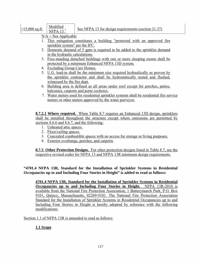
>15,000 sq.ft. Modified NFPA 13 1 See NFPA 13 for design requirements (section 21.37)
N/A = Not Applicable 1. This mitigation constitutes a building "protected with an approved fire
sprinkler system" per the IFC. 2. Domestic demand of 5 gpm is required to be added to the sprinkler demand
in the hydraulic calculations. 3. Free-standing detached buildings with one or more sleeping rooms shall be
protected by a minimum Enhanced NFPA 13D system. 4. Excluding Group Care Homes. 5. U.G. lead-in shall be the minimum size required hydraulically as proven by
the sprinkler contractor and shall be hydrostatically tested and flushed, witnessed by the fire dept.
6. Building area is defined as all areas under roof except for porches, patios, balconies, carports and porte cocheres.
7. Water meters used for residential sprinkler systems shall be residential fire service meters or other meters approved by the water purveyor.
8.7.2.1 Where required. When Table 8.7 requires an Enhanced 13D design, sprinklers shall be installed throughout the structure except where omissions are permitted by sections 8.6.6 and 8.6.7, and the following:
1. Unheated attic spaces. 2. Floor/ceiling spaces. 3. Concealed combustible spaces with no access for storage or living purposes. 4. Exterior overhangs, porches, and carports
8.7.3 Other Protection Designs. For other protection designs listed in Table 8.7, see the respective revised codes for NFPA 13 and NFPA 13R minimum design requirements.
“4701.4 NFPA 13R, Standard for the Installation of Sprinkler Systems in Residential Occupancies up to and Including Four Stories in Height” is added to read as follows:
4701.4 NFPA 13R, Standard for the Installation of Sprinkler Systems in Residential Occupancies up to and Including Four Stories in Height. NFPA 13R-2010 is available from the National Fire Protection Association, 1 Batterymarch Park, P.O. Box 9101, Quincy, Massachusetts, 02269-9101. The National Fire Protection Association Standard for the Installation of Sprinkler Systems in Residential Occupancies up to and Including Four Stories in Height is hereby adopted by reference with the following modifications:
Section 1.1 of NFPA 13R is amended to read as follows: 1.1 Scope
137

This standard covers the design and installation of automatic sprinkler systems for protection against fire hazards in residential occupancies up to and including two stories in height. Residential occupancies three or more stories in height shall be protected throughout in accordance with NFPA 13. When sprinkler protection is being provided to mitigate the minimum Fire Code requirements for fire flow, number of fire hydrants, or fire department access for single-family residential occupancies, the minimum design criteria shall be as outlined in Section 7.5 Protection Matrix for Group R Division 3 Occupancies and buildings built under the IRC.
Section 5.1.3 of NFPA 13R is amended to read as follows: 5.1.3 Rated Pressure. System components shall be rated for the maximum system working pressure to which they are exposed but shall not be rated at less than 175 psi (12.1 bar) for components installed aboveground and 150 psi (10.4 bar) for components installed underground. When the underground piping can be supplied or pressurized by a Fire Department Connection (FDC), the underground piping shall be designed to withstand a working pressure of not less than 200 psi (Class 200), or 50 psi greater than the system design pressure, whichever is greater.
Section 5.2.1 of NFPA 13R is amended to read as follows: 5.2.1 Pipe or tube used in sprinkler systems shall be of the materials specified in Table 5.2.1 or in accordance with 5.2.2. Piping shall have corrosion resistance ratio (CRR) of 1 or more.
Section 6.4.4 of NFPA 13R is amended to read as follows:
6.4.4 Where construction features or other special conditions exist that are outside the scope of sprinkler listings, listed sprinklers shall be permitted to be installed beyond their listing limitations, provided the installation conforms to a modification or alternative materials and methods report that has been approved by the authority having jurisdiction.
Section 6.6.4 of NFPA 13R is amended to read as follows: 6.6.4 Sprinklers shall be installed in any closet used for heating and air-conditioning equipment or containing fuel-fired equipment.
Section 6.6.5 of NFPA 13R is amended to read as follows: 6.6.5 Sprinklers shall not be required in any porches, balconies, corridors, and stairs that are open and attached, unless specifically required in any of these areas by the Building Code and/or Fire Code.
Section 6.6.6.1 of NFPA 13R is amended to read as follows:
138
6.6.6.1 Protection of Fuel-Fired Equipment. Where protection of fuel-fired equipment is required by 6.6.4, 6.6.6 and 6.6.7, sprinkler protection shall be provided in accordance with the following: (1) At least one quick-response sprinkler with a minimum k-factor of 5.6 shall be
provided above the fuel-fired equipment. Sprinklers shall be sufficient to cover the fuel-fired equipment protection area, which is equal to the entire perimeter of the fuel-fired equipment when viewed on a plan view.
(2) Where the sprinkler(s) protecting the fuel-fired equipment is located under a ceiling with slope equal to or greater than a 4:12 pitch, a minimum of one sprinkler shall be located above the edge of the fuel-fired equipment protection area, on the upslope side of the equipment.
(3) Freeze protection shall be provided in accordance with 5.4.2.
Section 6.6.7 of NFPA 13R is amended to read as follows: 6.6.7 Sprinklers shall not be required in closets on exterior balconies, regardless of size, as long as there are no doors or unprotected penetrations from the closet directly into the dwelling unit, and as long as the closet does not contain fuel-fired equipment.
Section 6.7.2.2.2 of NFPA 13R is amended to read as follows: 6.7.2.2.2 Where water supplies are known to have unusual corrosive properties and threaded or cut-groove steel pipe is to be used, wall thickness shall be in accordance with Schedule 30 [in sizes 8 inch or larger] or Schedules 40 [in sizes less than 8 inches]. Piping shall have corrosion resistance ratio (CRR) of 1 or more.
Section 6.8.2 of NFPA 13R is amended to read as follows: 6.8.2 The sprinkler system piping shall not have a separate control valve installed unless supervised by a central station, proprietary, or remote station alarm service.
Section 6.15 of NFPA 13R is hereby deleted in its entirety. Section 7.1.1.4 of NFPA 13R is amended to read as follows:
7.1.1.4 Systems installed in accordance with the single family residential protection matrix (Section 7.5) shall not require monitoring.
Section 7.5 of NFPA 13R is amended to read as follows: 7.5 Protection Matrix for Group R Division 3 Occupancies and buildings built under the IRC. When a sprinkler system is being installed to mitigate the minimum Fire Code requirements for fire flow, number of fire hydrants, or fire department access, the design requirements in Table 7.5 shall be applied.
139
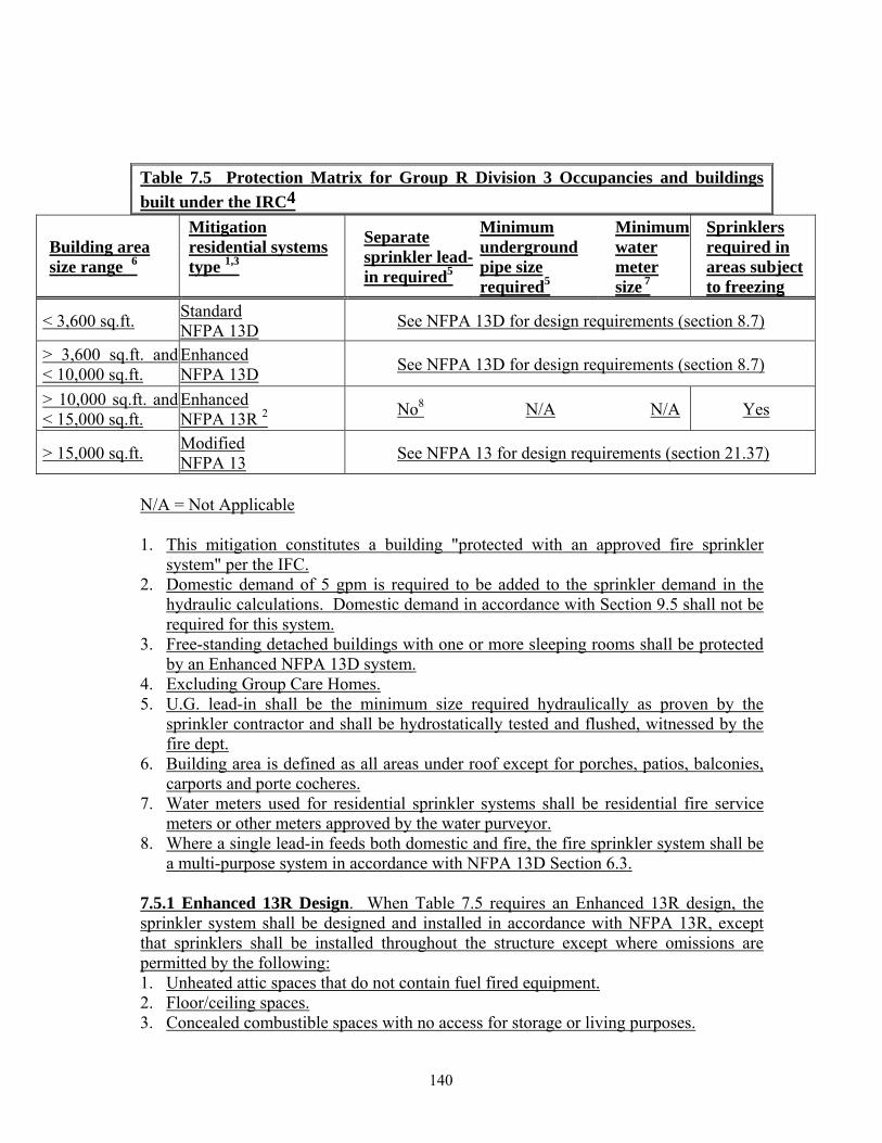
Table 7.5 Protection Matrix for Group R Division 3 Occupancies and buildings built under the IRC4
Building area size range 6
Mitigation residential systems type 1,3
Separate sprinkler lead-in required5
Minimum underground pipe size required5
Minimum water meter size 7
Sprinklers required in areas subject to freezing
< 3,600 sq.ft. Standard NFPA 13D See NFPA 13D for design requirements (section 8.7)
> 3,600 sq.ft. and < 10,000 sq.ft.
Enhanced NFPA 13D See NFPA 13D for design requirements (section 8.7)
> 10,000 sq.ft. and < 15,000 sq.ft.
Enhanced NFPA 13R 2 No8 N/A N/A Yes
> 15,000 sq.ft. Modified NFPA 13 See NFPA 13 for design requirements (section 21.37)
N/A = Not Applicable 1. This mitigation constitutes a building "protected with an approved fire sprinkler
system" per the IFC. 2. Domestic demand of 5 gpm is required to be added to the sprinkler demand in the
hydraulic calculations. Domestic demand in accordance with Section 9.5 shall not be required for this system.
3. Free-standing detached buildings with one or more sleeping rooms shall be protected by an Enhanced NFPA 13D system.
4. Excluding Group Care Homes. 5. U.G. lead-in shall be the minimum size required hydraulically as proven by the
sprinkler contractor and shall be hydrostatically tested and flushed, witnessed by the fire dept.
6. Building area is defined as all areas under roof except for porches, patios, balconies, carports and porte cocheres.
7. Water meters used for residential sprinkler systems shall be residential fire service meters or other meters approved by the water purveyor.
8. Where a single lead-in feeds both domestic and fire, the fire sprinkler system shall be a multi-purpose system in accordance with NFPA 13D Section 6.3.
7.5.1 Enhanced 13R Design. When Table 7.5 requires an Enhanced 13R design, the sprinkler system shall be designed and installed in accordance with NFPA 13R, except that sprinklers shall be installed throughout the structure except where omissions are permitted by the following: 1. Unheated attic spaces that do not contain fuel fired equipment. 2. Floor/ceiling spaces. 3. Concealed combustible spaces with no access for storage or living purposes.
140
4. Exterior overhangs, porches, and carports 7.5.2 Other Protection Designs. For other protection designs listed in Table 7.5, see the respective revised codes for NFPA 13 and NFPA 13D minimum design requirements.
Section 8.1.7 of NFPA 13R is amended to read as follows: 8.1.7 Sprinkler plans shall indicate the following: 1. Name of owner and occupant. 2. Location, including street address. 3. Point of compass. 4. Ceiling construction. 5. Full height cross section. 6. Ceiling/roof heights and slopes not shown in the full height cross section. 7. Location of fire walls. 8. Location of partitions, lintels, and doorways. Lintel openings require a cross section
view to indicate the area of the opening. 9. Occupancy, label, and name of all areas or rooms. 10. Location and size of concealed spaces, attics, closets, and bathrooms. 11. Any small enclosures in which no sprinklers are to be installed. 12. Size of city main in street; pressure; whether dead end or circulating, and, if dead end,
the direction and distance to nearest circulating main; and city main test results including elevation of the test hydrant.
13. Make, manufacturer, model, type, heat-response element, temperature rating, nominal K-factor, number of sprinklers installed, and nominal orifice size of the sprinkler, including sprinkler identification number.
14. Type and location of horn/strobes. 15. Type of pipe and fittings. 16. Pipe type and schedule of wall thickness. 17. Type of protection for nonmetallic pipe. 18. Nominal pipe size with lengths shown to scale. 19. Location and size of riser nipples. 20. Type of fittings and joints and the location of all welds and bends. 21. Type and locations of hangers, sleeves, braces, and methods of securing sprinklers,
where applicable. 22. All control valves, check valves, drain pipes, and test connections. 23. Underground pipe size, length, location, weight, material, and point of connection to
city main; type of valves, meters, and valve pits; and depth at which the top of the pipe is laid below grade.
24. In case of hydraulically designed systems, the information on the hydraulic data nameplate.
25. Name, address, phone number, and contractor’s license number of sprinkler contractor.
26. Nevada State Fire Marshal registration number. 27. Signature and NICET number, or engineer’s seal, of the designer. 28. General notes as required by the AHJ.
141
29. Approximate capacity in gallons of each dry pipe system. 30. Make, type, model, and size of alarm or dry pipe valve. 31. Piping provisions for flushing. 32. Where the equipment is to be installed as an addition to an existing system, enough of
the existing system indicated on the plans to make all conditions clear. 33. A graphic representation of the scale used on all plans. 34. Hydraulic reference points shown on the plan that correspond with comparable
reference points on the hydraulic calculation sheets. 35. The minimum rate of water application (density or flow or discharge pressure), the
design area of water application, and the domestic demand. 36. The total quantity of water and the pressure required noted at a common reference
point for each system. 37. Relative elevations of sprinklers, junction points, and supply or reference points. 38. Information about backflow preventers (manufacturer, size, type). 39. Information about antifreeze solution used (type and amount). 40. Size and location of hydrants, showing size and number of outlets. Static and residual
hydrants that were used in flow tests shall be shown. 41. Size, location, and piping arrangement of fire department connections. 42. Location of fuel-fired equipment and heating and air-conditioning equipment. 43. Location of closets on exterior balconies, and a note indicating whether there is any
type of door or penetration between the closet and the dwelling unit. 44. Edition year of NFPA 13R to which the sprinkler system is designed. 45. Utility plans and/or plumbing plans necessary to show connection from water supply
to fire sprinkler system.
“4701.5 NFPA 14, Standard for the Installation of Standpipes and Hose Systems”, is added to read as follows:
4701.5 NFPA 14, Standard for the Installation of Standpipes and Hose Systems. NFPA 14-2010 is available from the National Fire Protection Association, 1 Batterymarch Park, P.O. Box 9101, Quincy, Massachusetts, 02269-9101. The National Fire Protection Association Standard for the Installation of Standpipes and Hose Systems is hereby adopted by reference with the following modifications:
Section 3.3.5 of NFPA 14 is amended to read as follows: 3.3.5 High-Rise Building. A building where the floor of an occupiable story is greater than 55 ft (17 m) above the lowest level of fire department vehicle access.
Section 4.2.3.2 of NFPA 14 is added to read as follows: 4.2.3.2 Where system pressures exceed 300 psi, piping expected to experience greater than 300 psi at zero flow shall be rated for the pressures expected, and have minimum nominal pipe wall thickness in accordance with Schedule 40.
142
Section 4.6.1.1.1 of NFPA 14 is amended to read as follows: 4.6.1.1.1 Within the cabinet, the hose connections shall be located so that there is at least 1 in. (25.4 mm) between any part of the cabinet and the handle of the valve when the valve is in any position ranging from fully open to fully closed, 6 in (150 mm) clearance perpendicular from the valve handle to any part of the cabinet, and 6 in (150 mm) clearance around the circumference of outlet to any part of the cabinet. The door shall not be considered to be part of the cabinet for the purposes of this section.
Section 4.8.2 of NFPA 14 is amended to read as follows: 4.8.2 Each fire department connection shall have at least two, and not less than one for each 250 gpm of system demand or fraction thereof, 2 ½ inch (65 mm) internal threaded fittings having NHS threads, as specified in NFPA 1963, Standard for Fire Hose Connections. Fire Department Connections shall be provided with internal check valve(s) such that water being supplied into any inlet will not flow back out of any other inlet. For the purposes of this section, internal clapper valve devices provided by the manufacturer in listed Fire Department Connections shall be considered internal check valves. (See Section 7.7 and 7.12 for design requirements)
Section 4.8.2.3 of NFPA 14 is added to read as follows: 4.8.2.3 Fire department connection piping shall be a minimum of 4 in (100 mm) for three or fewer inlets, a minimum of 6 in (150 mm) for four or more inlets, and shall in all cases have a diameter equal or greater to the largest supply line.
Section 5.2.1.2.1 of NFPA 14 is amended to read as follows: 5.2.1.2.1 Piping volume shall not be limited where the system is designed in accordance with Section 5.2.1.3.2.
Section 5.2.1.2.2 of NFPA 14 is amended to read as follows: 5.2.1.2.2 System design shall be such that water is delivered to the system at the most remote hose connection in not more than 3 minutes, starting at the normal air pressure on the system and at the time of fully opened hose connection.
Section 6.1.2.2.1 of NFPA 14 is amended to read as follows: 6.1.2.2.1 In buildings constructed of Type I or Type II construction in accordance with the International Building Code or in buildings equipped with an approved automatic sprinkler system, standpipes shall not be required to be protected by fire rated construction.
Section 6.3.2.1 of NFPA 14 is added to read as follows:
143
6.3.2.1 Individual hose valves fed from the feed main shall each be provided with an isolation valve, such that maintenance of the individual hose valve can be accomplished without interrupting the supply to standpipes fed from the feed main.
Section 6.3.7.1 of NFPA 14 is amended to read as follows: 6.3.7.1 System water supply valves, isolation control valves, and other valves in feed mains shall be electrically supervised in an approved manner in the open position by a central station, proprietary, or remote station signaling service
Section 6.4.5.2.2 of NFPA 14 is hereby deleted in its entirety.
Section 6.4.5.3 of NFPA 14 is amended to read as follows: 6.4.5.3 Signs shall be provided at fire department connections, indicating the areas of the building served and the minimum required pressure and flow to be delivered through the inlets. Where a fire department connection services multiple buildings, structures, or locations, the sign shall indicate the buildings, structures, or locations served.
Section 6.4.5.3.1 of NFPA 14 is added to read as follows: 6.4.5.3.1 Signs shall have a red background and be professionally engraved with white lettering a minimum of 1 in. (25.4 mm) in height, with a minimum stroke of ¼ in. Signs shall consist of durable, weatherproof materials, subject to approval by the authority having jurisdiction.
Section 7.2.1 of NFPA 14 is amended to read as follows: 7.2.1 The maximum pressure at any point in the system at any time shall not exceed 350 psi (24 bar), except where components are rated for higher pressures and are approved by an alternative materials and methods report approved by the authority having jurisdiction.
Section 7.2.3.2 of NFPA 14 is amended to read as follows: 7.2.3.2 Where the static pressure exceeds 175 psi (12.1 bar) at a 1½ in. (40 mm) hose connection or exceeds 200 psi (13.9 bar) at a 2½ in. (65 mm) hose connection, an approved pressure-regulating device shall be provided to limit static and residual pressures at the outlet of the hose connection to 100 psi (6.9 bar) for 1½ in. (40 mm) hose connections and 200 psi (13.9 bar) for other hose connections. The pressure on the inlet side of the pressure-regulating device shall not exceed the device’s rated working pressure.
Section 7.2.3.4 of NFPA 14 is amended to read as follows: 7.2.3.4 Where hose valve pressure regulating devices are installed on 2 ½ in. (65 mm) outlets, they shall be field adjustable, capable of being adjusted through the full
144
adjustment range by a 3/8 in. (12 mm) rod with a maximum required torque of 30 foot-pounds (41 nm) while flowing water. Field adjustment shall not require any hose valve disassembly.
Section 7.2.4 of NFPA 14 is amended to read as follows: 7.2.4 When system pressure-regulating devices are used in lieu of providing separate pumps, multiple zones shall be permitted to be supplied by a single pump and pressure regulating device(s) under the following conditions: (1) Pressure-regulating device(s) shall be permitted to control pressure in the lower
zone(s). A redundant pressure-regulating device shall be provided in parallel configuration for the full range of anticipated system flow. Where multiple sizes of pressure-regulating devices are required to achieve flow through the entire range of anticipated system flow, each size shall have a redundant pressure-regulating device installed.
(2) A method to isolate each of the pressure-regulating device(s) shall be provided for maintenance and repair by providing control valves on the supply and discharge side of each pressure-regulating device, in a manner where only the device being maintained and repaired is out of service.
(3) Regulating devices shall be arranged so that the failure of any single device does not allow pressure in excess of 200 psi (13.9 bar) to not more than two hose connections
(4) An equally sized bypass around the pressure regulating device(s), with a normally closed valve, shall be installed.
(5) Pressure-regulating devices and the bypass valve shall be installed not more than 7ft 6in (2.31 m) above the floor.
(6) The pressure-regulating device shall be provided with inlet and outlet pressure gauges.
(7) The fire department connection(s) shall be connected between the system fire pump(s) and the pressure-regulating device(s) and shall be sized and designed to allow the fire department connection to provide full back-up for the system fire pump to all pressure zones.
(8) The pressure-regulating device shall be provided with a pressure relief valve sized for the full anticipated system flow and capable of maintaining downstream system pressures below the maximum pressure ratings for all system components.
(9) Remote monitoring and supervision for detecting high pressure failure of the pressure of the pressure-regulating device shall be provided in accordance with NFPA 72, National Fire Alarm Code. Such failure shall be detected by providing a flow switch downstream on the pressure relief valve.
(10) A drain sufficient to allow flow of the full anticipated system flow shall be provided adjacent to the pressure-regulating devices. Use of this drain line for discharge from the pressure relief valve shall be permitted.
Section 7.3.2 of NFPA 14 is amended to read as follows:
145

7.3.2 Class I Systems. Class I systems shall be provided with 2 ½ in. (65 mm) hose connections in the following locations: (1) At each main level floor landing in exit stairways. (2) On each side of the wall adjacent to the exit openings of horizontal exits, unless permitted to be omitted by the Fire Code (3) In other than covered mall buildings, in each exit passageway at the entrance from the building areas into the passageway (4) In covered mall buildings, at the entrance to each exit passageway or exit corridor, and at the interior side of public entrances from the exterior to the mall (5) At the highest landing of stairways with stairway access to a roof, and on roofs with a slope of less than 3 in 12 where stairways do not access the roof
Section 7.3.2.2 of NFPA 14 is amended to read as follows: 7.3.2.2 Class I hose systems shall be designed so that all floor areas of the floor or story are protected by hose valve coverage, with 100 feet of hose and 30 feet of stream from each hose valve connection. The length of hose shall be measured along approved walking paths, and the stream distance shall not be expected to turn corners. Where the most remote portion of a floor or story is not protected with the hose valves already provided in accordance with 7.3.2 subject to these distance limitations, additional hose connections shall be provided, in approved locations.
Section 7.3.3.1 of NFPA 14 is amended to read as follows: 7.3.3.1 Class II systems shall be provided with 1 ½ in. (40 mm) hose stations so that all portions of each floor level of the building or area thereof required to be protected are within 130 ft (39.7 m) of a hose connection provided with 1 ½ in. (40 mm).
Section 7.4 of NFPA 14 is amended to read as follows: 7.4 Number of Standpipes. Separate standpipes shall be provided in each required exit stairway. Scissor stairs having two separate landings on each level shall be provided with a separate hose connection on each stair landing.
Section 7.8.1 of NFPA 14 is amended to read as follows: 7.8.1 Minimum Design Pressure for Hydraulically Designed Systems. Hydraulically designed standpipe systems shall be designed to provide the waterflow rate required by Section 7.10 at a minimum residual pressure of 125 psi (8.6 bar) at the outlet of the hydraulically most remote 2 ½ in. (65 mm) hose connection and 65 psi (4.5 bar) at the outlet of the hydraulically most remote 1 ½ in. (40 mm) hose station.
Section 7.8.1.1 of NFPA 14 is amended to read as follows:
146

7.8.1.1 Manual standpipe systems shall be designed to provide 125 psi (8.6 bar) at the topmost outlet with the calculations terminating at the fire department connection.
Section 7.9.1.3 of NFPA 14 is added to read as follows: 7.9.1.3 Where pumps are used in structures with an occupied floor located greater than 250 ft in height above the lowest level of fire department access, a redundant fire pump shall be provided for each required fire pump.
Section 7.11.1.1 of NFPA 14 is amended to read as follows: 7.11.1.1 The drain riser shall be equipped with tees that are of the same size as the discharge outlets of the pressure-regulating devices to be tested with internal threaded swivel fitting having NHS threads, as specified in NFPA 1963, Standard for Fire Hose Connections, with plugs, and shall be located at every floor with a hose valve pressure-regulating device. A 2 ½ in. (65 mm) drain connection shall be provided adjacent to every hose valve pressure-regulating device, even if the pressure-regulating device is not on a vertical standpipe riser.
Section 7.11.1.3 of NFPA 14 is amended to read as follows: 7.11.1.3 Where drain risers are interconnected and run to a common discharge point, all piping shall be sized for the maximum possible combined flow.
Section 7.12.1.1 of NFPA 14 is amended to read as follows: 7.12.1.1 In buildings with multiple pump zones, an express fire department connection shall be provided from the street level to each respective pump zone(s).
Section 7.9.1 of NFPA 14 is amended to read as follows: 7.9.1 Each standpipe system zone created due to system component pressure limitations, requiring pumps, shall be provided with either a separate pump or with pressure-regulating devices as specified in 7.2.2.
Section 7.9.3.2 of NFPA 14 is amended to read as follows: 7.9.3.2 Both of the lines specified in 7.9.3.1 shall be arranged so that the supply can be automatically delivered from the lower to the higher zone.
Section 7.11.1 of NFPA 14 is amended to read as follows: 7.11.1 A permanently installed drain riser shall be provided adjacent to each standpipe equipped with pressure-regulating devices to facilitate tests of each device. The drain shall be sized large enough to handle the full flow required from the largest pressure-regulating device, but shall not be less than 3 in. (76 mm) diameter.
147
Section 7.12.2.1 of NFPA 14 is hereby deleted in its entirety.
Section 7.12.3 of NFPA 14 is amended to read as follows:
7.12.3 Fire department connection sizes shall be based on the greater of the sprinkler system demand (if a combined system) or the standpipe system demand and shall include one 2 ½ in. (65 mm) inlet per every 250 gpm (946 L/min)
Section 7.12.3.1 of NFPA 14 is hereby deleted in its entirety.
Section 8.1.1 of NFPA 14 is amended to read as follows: 8.1.1 Plans accurately showing the details and arrangement of the standpipe system shall be furnished to, reviewed, and stamped accepted by the authority having jurisdiction prior to the installation of the system.
Section 8.1.6 of NFPA 14 is added to read as follows: 8.1.6 Plans shall include the following items:
1. Provide a detailed narrative describing the scope of work to be conducted associated
with the plans. 2. Name of owner and occupant. 3. Location, including street address. 4. Name address, phone number, and contractor’s license number of sprinkler
contractor. 5. Nevada State Fire Marshal registration number. 6. Signature and NICET number, or engineer’s seal, of the designer. 7. General notes as required by the AHJ. 8. Point of compass. 9. The plan must show a top view of all areas on a common architectural scale, i.e. 1/8”,
3/16”, 1/4", etc. All walls and doors need to be shown, and each room must be labeled according to use. The top view must show supply and drain pipe layout, pipe dimensions, attachments, braces, hangers, standpipe hose outlets, hydraulic nodes, and the coverage area from each hose valve to the remote areas of the floor plan. The coverage area shall be shown on plans and be measured along the path of travel from hose valves, around walls and through doors, to the most remote areas of the floor. The 30 feet distance assigned to the hose stream shall not be allowed to bend or turn.
10. The plan must show section views with a riser diagram to describe the locations of mains, lines, and hose valves within the structure. A minimum of one view is required, although additional views may be necessary to determine compliance with NFPA 14. The section view must be drawn to a common architectural scale, i.e. 1/8”, 3/16”, 1/4", etc. The riser diagram must indicate all components on the riser, including fire department connections; water supply components, including fire pumps and supply lines; interconnecting horizontal pipe; all standpipes on the system;
148
control valves at the base of all standpipes; hose valves fed by the standpipes; and, where required for testing of pressure regulating valves, the drain lines.
11. The plans shall include an isometric view showing the entire system in one view. 12. A graphic representation of the scale used on all plans. 13. Ceiling construction. 14. Full height cross section. 15. Location of fire walls. 16. Location of horizontal exits. 17. Location of partitions. 18. Label and name of each area or room. 19. General notes shall be provided, as follows:
a. Indicate compliance with NFPA 14. b. Indicate the type of system per Section 5.2 and the class of the system per Section
5.3. c. Indicate the minimum and maximum pressure requirements for the system. d. Indicate the minimum flow for the system and for each individual valve. e. Provide a description of hose valves used, detailing the manufacturer, model
number(s), and outlet size. f. Manufacturer, schedule and type of piping. g. Manufacturer and type of fittings. h. Type of freeze protection (building heated, dry system, anti-freeze system, heat-
trace, etc). i. Indicate the pressure required for the hydrostatic test, being 200 psi or 50 psi
about pump churn pressure, whichever is higher. j. Indicate the quantity of hose valves shown on the submittal.
20. Underground pipe size, length, location with respect to the building, weight, material, and point of connection to city main; type of valves, meters, and valve pits; and depth at which the top of the pipe is laid below grade. Show the locations of fire hydrants used for water supply to the fire department connection(s), indicate the test and flow test results and label the test and flow hydrants.
21. Provide information regarding the fire pump, as applicable. 22. Other sources of water supply, including water storage tanks and fire department
connections, shall be shown on plans. 23. Size, location, and piping arrangement of fire department connections, with details of
the connection. 24. Fire Department Connection Signage: A sign shall be provided adjacent to each FDC
indicating what systems are being served, what areas of the building are served, and the minimum required pressure and flow at the Fire Department Connection for correct system operation. Provide a detail of this sign on the plan.
25. Detail of Class I. Class II, or Class III hose valves located in cabinets. The cabinet size, and the placement of items within the cabinet, shall be such to provide a minimum clearance of 6 inches perpendicularly from the face of the valve, a minimum of 1 inch around the circumference of the valve, and a minimum of 6 inches around the circumference of the hose outlet cap.
26. Type of pipe and fittings. 27. Pipe type and schedule of wall thickness.
149
28. Nominal pipe size with lengths shown to scale. 29. Type of fittings and joints and the location of all welds and bends. 30. Type and locations of hangers, sleeves, braces, and methods of securing sprinklers,
where applicable. 31. Show hanger locations, and provide details of hanger installations. 32. Seismic bracing information shall be provided, including locations, details, and
calculations. 33. Provide details for penetrations of standpipe piping through walls, floors, and other
structural members. Show detail to note clearances around the piping and/or locations of flexible connections.
34. Provide details for all penetrations in rated walls and floors, providing information regarding the method of maintaining fire rating of the wall or floor.
35. All control valves, check valves, drain pipes, and test connections. 36. Make, type, model, and size of alarm or dry pipe valve. 37. Piping provisions for flushing and for testing. 38. Where the equipment is to be installed as an addition to an existing system, enough of
the existing system indicated on the plans to make all conditions clear. 39. A detail of the hydraulic data nameplate. 40. Hydraulic reference points shown on the plan, including the top view, section view,
and isometric view that correspond with comparable reference points on the hydraulic calculation sheets.
41. The total quantity of water and the pressure required noted at a common reference point for each system.
42. Edition year of NFPA 14 to which the standpipe system is designed. 43. Pressure Reducing Valves: For all pressure reducing valves, including direct-acting
and pilot-operated valves, which are shown on the plans, indicate the make, model, and setting of the pressure-reducing valve, and provide a detail for each unique installation configuration.
44. Where direct-acting pressure regulating hose valves are provided anywhere in the building, provide a chart on the plans. The chart shall have eight columns, as follows: a. Floor Level – Provide numerical designation for all floor levels in the building. b. Static Pressure, Inlet – Indicate the static pressure at the inlet of the hose valve on
all floor levels. Provide a supporting hydraulic. calculation at zero flow with churn pressure, providing a node at the hose valve on each floor level to indicate the static pressure at each hose valve.
c. Residual Pressure, Full Flow, Inlet – Indicate the residual pressure at the inlet of hose valves on each floor. Provide a supporting hydraulic calculation at full standpipe design flow per NFPA 14 (750 or 1,000 gpm), providing a node on each floor level to indicate the residual pressure at each hose valve.
d. Residual Pressure, 250-gpm flow, inlet - Indicate the residual pressure at the inlet of hose valves on each floor while flowing 250 gpm. Provide a supporting hydraulic calculation at 250 gpm flow at the most remote standpipe outlet, providing a node on each floor level of the most remote standpipe to indicate the residual pressure at each hose valve.
150
e. Valve Make and Model – Indicate the manufacturer of the valve on all floors, and the model number for the specific valve. Provide supporting manufacturer specifications.
f. Valve Setting – Indicate the hose valve setting or bonnet number proposed for each valve. The setting or bonnet number must be associated with the manufacturer specifications for the valve.
g. Residual Pressure, Full Flow, Outlet – Indicate the residual outlet pressure at the outlet of the hose valve under the full-flow condition. For PRV installations, the residual pressure is taken from pressure relation charts provided by the manufacturer. For non-PRV installation, the residual pressure is taken by analysis of the equivalent lengths of the fittings and the hose valve.
h. Residual Pressure, 250-gpm flow, Outlet - Indicate the residual outlet pressure at the outlet of the hose valve when flowing 250 gpm. This is necessary to establish the residual pressure expected during field inspection. For PRV installations, the residual pressure is taken from pressure relation charts provided by the manufacturer.
Section 11.5.6.2 of NFPA 14 is amended to read as follows:
11.5.6.2 The system shall deliver a minimum of 250 gpm (946 L/min) at the hose connection within 3 minutes of opening the hose valve.
Section 12.7.2 of NFPA 14 is amended to read as follows: 12.7.2 Where temporary standpipes normally contain water, the piping shall be protected against freezing, unless otherwise approved by the authority having jurisdiction.
“4701.6 NFPA 20, Standard for the Installation of Stationary Pumps for Fire Protection”, is added to read as follows:
4701.6 NFPA 20, Standard for the Installation of Stationary Pumps for Fire Protection. NFPA 20-2010 is available from the National Fire Protection Association, 1 Batterymarch Park, P.O. Box 9101, Quincy, Massachusetts, 02269-9101. The National Fire Protection Association Standard for the Installation of Stationary Pumps for Fire Protection is hereby adopted by reference with the following modifications:
Section 3.3.24 of NFPA 20 is amended to read as follows: 3.3.24 High-Rise Building. A building where the floor of an occupiable story is greater than 55 ft (16.8 m) in height above the lowest level of fire department vehicle access.
Section 4.1.3 of NFPA 20 is added to read as follows: 4.1.3 Where a pump is used to provide booster pressure supply to multiple structures, a redundant fire pump shall be provided for each required fire pump.
151
Section 4.2.1.1 of NFPA 20 is added to read as follows: 4.2.1.1 A fire pump for fire protection shall be selected to operate at less than or equal to 110 percent of the rated capacity
Section 4.8.1 of NFPA 20 is amended to read as follows: 4.8.1 A centrifugal fire pump for fire protection shall be selected so that the greatest single demand for any fire protection system connected to the pump is less than or equal to 110 percent of the rated capacity (flow) of the pump.
Section 4.10.1.1 of NFPA 20 is amended to read as follows: 4.10.1.1 A liquid-filled pressure gauge having a dial not less than 3.5 in. (89 mm) in diameter shall be connected near the discharge casting with a 0.25 in. (6.25-mm) gauge valve.
Section 4.10.2.1 of NFPA 20 is amended to read as follows: 4.10.2.1 Unless the requirements of 4.10.2.4 are met, a liquid-filled compound pressure and vacuum gauge having a dial not less than 3.5 in. (89 mm) in diameter shall be connected to the suction pipe near the pump with a 0.25 in. (6.25-mm) gauge valve.
Section 4.12.1.1.1 of NFPA 20 is amended to read as follows: 4.12.1.1.1 Fire pump units shall be protected from surrounding occupancies by a minimum of 2-hour fire-rated construction or physically separated from the protected building by a minimum of 50 ft (15.3 m).
Table 4.12.1.1.2 of NFPA 20 is hereby deleted in its entirety.
Section 4.12.1.3 of NFPA 20 is amended to read as follows: 4.12.1.3 Fire Pump Buildings or Rooms. Fire pump buildings or rooms shall be protected with an automatic sprinkler system installed in accordance with NFPA 13, Standard for the Installation of Sprinkler Systems.
Section 4.12.2.1.1 of NFPA 20 is amended to read as follows: 4.12.2.1.1. Fire pump rooms not directly accessible from the outside shall be accessible through an enclosed passageway from an enclosed stairway or exterior exit. The enclosed passageway and/or stairway shall have a minimum 2-hour fire-resistance rating. The travel distance through the enclosed passageway shall not exceed 50 feet.
152
Section 4.12.3.1 of NFPA 20 is amended to read as follows:
4.12.3.1 An approved or listed permanently installed (hard-wired for electrically powered devices) source of heat shall be provided for maintaining the temperature of a pump room or pump house above 40º F (5º C).
Section 4.12.4 of NFPA 20 is amended to read as follows: 4.12.4 Normal Lighting. Artificial permanently installed lighting shall be provided in a pump room or house.
Section 4.14.4.1 of NFPA 20 is amended to read as follows: 4.14.4.1 All pumps shall be installed with a bypass. (See Figure A.4.14.4.)
Section 5.1.1.3 of NFPA 20 is added to read as follows: 5.1.1.3 Where pumps are used in structures with walking levels greater than 250 ft in height about the lowest level of fire department access, a redundant fire pump shall be provided for each required fire pump.
Section 9.3.1 of NFPA 20 is amended to read as follows:
9.3.1 At least one alternate source of power shall be provided when the requirement of 9.3.3 is not satisfied.
Section 9.3.4 of NFPA 20 is amended to read as follows: 9.3.4 When provided, the alternate source of power shall be supplied from one of the following sources: (1) A generator installed in accordance with Section 9.6. (2) One of the sources identified in 9.2.2(1), 9.2.2(2), 9.2.2(3), or 9.2.2(5) when the
power is provided distinctly independent of the normal source of power. Any connections to the public utility shall be considered a single source of power and subsequently cannot be utilized as both normal power and the alternate (backup) power.
Section 10.2.1 of NFPA 20 is amended to read as follows:
10.2.1 Controllers shall be located as close as is practical to the motors they control and shall be within sight of the motors. Additionally, the controllers shall be readily accessible by locating controllers near the entrance to the room, and shall comply with clearance requirements from the National Electrical Code.
Section 10.4.7.1.1 of NFPA 20 is added to read as follows:
153
10.4.7.1.1 Where the fire pump serves a building equipped with a Fire Command Center, the signal(s) required remote from the controller shall be indicated both on a dedicated panel provided by the fire pump manufacturer and on the fire alarm control panel.
Section 12.2.1 of NFPA 20 is amended to read as follows: 12.2.1 Controllers shall be located as close as is practical to the motors they control and shall be within sight of the motors. Additionally the controllers shall be readily accessible by locating controllers near the entrance to the room and shall comply with clearance requirements from the National Electrical Code.
Section 12.4.2.1.1 of NFPA 20 is amended to read as follows: 12.4.2.1.1 Where the fire pump serves a building equipped with a Fire Command Center, the signal(s) required remote from the controller shall be indicated both on a dedicated panel provided by the fire pump manufacturer and on the fire alarm control panel.
“4701.7 NFPA 22, Standard for Water Tanks for Private Fire Protection”, is added to read as follows:
4701.7 NFPA 22, Standard for Water Tanks for Private Fire Protection. NFPA 22-2008 is available from the National Fire Protection Association, 1 Batterymarch Park, P.O. Box 9101, Quincy, Massachusetts, 02269-9101. The National Fire Protection Association Standard for Water Tanks for Private Fire Protection is hereby adopted by reference with the following modifications:
Section 5.1.1.1 of NFPA 22 is added to read as follows: 5.1.1.1 Steel tanks shall be designed in accordance with AWWA D100, Welded Steel Tank for Water Storage, 1996, or AWWA D103, Factory-Coated Bolted Steel Tanks for Water Storage, 1997.
Section 14.4.1 of NFPA 22 is amended to read as follows: 14.4.1 A permanent connection to an approved water supply shall be provided to fill the tank. Where the tank serves as a break tank between the city supply and fire pump(s), the fill shall be through automatic fill valves that are tied to water level sensors, and a bypass line of equal size with a normally closed control valve shall be provided.
Section 14.4.2 of NFPA 22 is amended to read as follows: 14.4.2 The means to fill the tank shall be sized to fill the tank in a maximum time of 8 hours. Where the tank serves as a break tank between the city supply and building fire
154
pump(s), the means to fill the tank shall be automatic and shall provide supply flow equal to 150% of the fire pump rated flow.
Section 14.5.5 of NFPA 22 is amended to read as follows: 14.5.5 Discharge The overflow pipe shall discharge water to a drain with flow capacity equal to or greater than the fill line supply flow, or to an approved exterior location subject to approval by the authority having jurisdiction.
Section 14.8.1.1 of NFPA 22 is added to read as follows: 14.8.1.1 Where the water storage tank acts as a break tank between the city supply and fire pump(s), water level sensors shall be provided. A minimum of three sensor levels shall be provided. Two sensor levels shall activate the turn-on/turn-off of the fill valve. The third sensor level shall indicate a low level alarm. The sensor that opens the fill control valve shall be set 5 inches (127 mm) below normal (full) level, or at 90% of the normal (full) volume, whichever leaves the greater volume in the tank. The sensor that closes the fill control valve shall be set at normal (full) level. The sensor that signals a low alarm shall be set 12 inches (300 mm) below normal (full) level, or at 70% of the normal (full) volume, whichever leaves the greater volume in the tank. The low level alarm shall be transmitted to a constantly attended location to initiate response to the fill control bypass valve.
“4701.8 NFPA 24, Standard for the Installation of Private Fire Service Mains and Their Appurtenances”, is added to read as follows:
4701.8 NFPA 24, Standard for the Installation of Private Fire Service Mains and Their Appurtenances. NFPA 24-2007 is available from the National Fire Protection Association, 1 Batterymarch Park, P.O. Box 9101, Quincy, Massachusetts, 02269-9101. The National Fire Protection Association Standard for the Installation of Private Fire Service Mains and Their Appurtenances is hereby adopted by reference with the following modifications:
Section 6.5.2 of NFPA 24 is amended to read as follows: 6.5.2 A sectional valve shall be provided at the following locations: (1) On each bank where a main crosses water (2) Outside the building foundation(s) where a main or a section of a main runs under a building (3) On the underground line where there are two sources of water, after every 2 fire hydrants or building fire sprinkler connections
“4701.9 NFPA 72, National Fire Alarm Code”, is added to read as follows:
155

4701.9 NFPA 72, National Fire Alarm Code. NFPA 72-2010 is available from the National Fire Protection Association, 1 Batterymarch Park, P.O. Box 9101, Quincy, Massachusetts, 02269-9101. The National Fire Protection Association National Fire Alarm Code is hereby adopted by reference with the following modifications:
Section 3.3.5.2 of NFPA 72 is added to read as follows: 3.3.7.2 False Alarm. Activation or reporting of an alarm for which no such alarm condition, fire or emergency actually exists. Additionally, False Alarm is the willful and knowing initiating or transmission of a signal, message or other notification of an event of fire when no such danger exists.
Section 3.3.95.4.2 of NFPA 72 is amended to read as follows: 3.3.95.4.2 Dedicated Function Fire Alarm System. A protected premises fire alarm system installed specifically to perform fire safety function(s) where a building fire alarm system is not required. Such systems include, but are not limited to, sprinkler monitoring systems and elevator recall systems.
Section 10.5.5.1 of NFPA 72 is amended to read as follows:
10.5.5.1 Dedicated Branch Circuit. A dedicated branch circuit shall supply primary power from a commercial light and power source. Exceptions: (1) When approved by the AHJ, an engine-driven generator or equivalent in accordance with 4.4.1.9.2, where a person specifically trained in its operation is on duty at all times may be used for a specified period of time. (2) When approved by the AHJ, an engine-driven generator or equivalent arranged for cogeneration with commercial light and power in accordance with 4.4.1.9.2, where a person specifically trained in its operation is on duty at all times may be used.
Section 10.15 of NFPA 72 is amended to read as follows: 10.15 Protection of Fire Alarm System. In areas that are not continuously occupied, automatic smoke detection shall be provided at the location of each fire alarm control unit(s), notification appliance circuit power extenders, and supervising station transmitting equipment to provide notification of fire at that location. Exception No. 1: Where ambient conditions prohibit installation of automatic smoke detection, automatic heat detection shall be permitted. Exception No. 2: Dedicated function fire alarm systems shall not have smoke detectors installed above the dedicated function fire alarm control unit.
156
Section 10.16.1 of NFPA 72 is amended to read as follows: 10.16.1 Alarm Annunciation: Alarm annunciators shall comply with all of the following:
1. If a building has a main entrance/foyer, a remote annunciator shall be provided inside the building at the main entrance/foyer.
Exception: When the fire alarm control unit is located inside the building at the main entrance/foyer, a remote annunciator is not required at the main entrance/foyer.
2. If a building has a fire riser room with an exterior door, a remote annunciator shall be provided within the fire riser room.
Exception: When the fire alarm control unit is located within the fire riser room, a remote annunciator is not required within the fire riser room.
3. The location of an operated initiating device shall be displayed by alphanumeric display at the annunciator.
4. The alphanumeric display shall state the device type, the floor level (if applicable), the device address and a descriptive location for the operated device(s).
5. The visible annunciation of the location of operated initiating devices shall not be canceled by the means used to deactivate alarm notification appliances.
Section 10.16.1.1 of NFPA 72 is hereby deleted in its entirety.
Section 10.16.1.2 of NFPA 72 is hereby deleted in its entirety.
Section 10.16.1.3 of NFPA 72 is hereby deleted in its entirety.
Section 12.2.4 of NFPA 72 is amended to read as follows: 12.2.4 The installation of all pathway wiring, cable and equipment shall be in accordance with NFPA 70, National Electric Code and the applicable requirements of 12.2.4.1 through 12.2.4.5. In all occupancies, other than residential two stories or less, all wiring, including optical fiber cables, shall be in enclosed metallic conduit or shall be MI, MC, or AC cable. (SIG-FUN)
Section 17.5.3.1 of NFPA 72 is amended to read as follows: 17.5.3.1 Total (Complete) Coverage. Where required by laws, codes, or standards, and unless otherwise modified by 17.5.3.1.1 through 17.5.3.1.5, total coverage shall include all rooms, halls, storage areas and basements. Attics, lofts, spaces above suspended ceilings, and other subdivisions and accessible spaces; and the inside of all closets, elevator shafts, enclosed stairways, dumbwaiter shafts, and chutes shall also have detectors if required by the AHJ or to satisfy performance design criteria. Inaccessible areas may not be required to be protected by detectors.
157
Section 17.5.3.1.6 of NFPA 72 is added to read as follows:
17.5.3.1.6 When detectors are installed instead of duct smoke detectors to comply with the Uniform Mechanical Code, total coverage is defined as the area served by the air-moving equipment.
Section 17.6.3.5.2 of NFPA 72 is hereby deleted in its entirety.
Section 17.7.3.1.3 of NFPA 72 is amended to read as follows: 17.7.3.1.3 If the intent is to protect against a specific hazard, and the detectors are not otherwise required by this code or other applicable codes, the detector(s) shall be permitted to be installed closer to the hazard in a position where the detector can intercept the smoke.
Section 17.12.2 of NFPA 72 is amended to read as follows: 17.12.2 Activation of the initiating device shall occur within 60 seconds of waterflow at the alarm-initiating device when flow occurs that is equal or greater than that from a single sprinkler of the smallest orifice size installed in the system. Section 18.3.2.4 of NFPA 72 is added to read as follows:
Section 18.3.2.4 of NFPA 72 is amended to read as follows: 18.3.2.4 Voltage drop calculations shall be performed using one of the following methods: (1) The lump sum calculation method, which shall be calculated as follows:
(a) Calculate the voltage drop using one of these formulas: i. VD = I * ((R * 2 * L)/1,000) OR
ii. VD = (2 * K * I * L)/CM. (b) Subtract this calculated voltage drop from 20.4 volts (VS) in order to get the
voltage value at the end of the circuit (VS – VD = VEOL). The value for VEOL shall be a minimum of 16 volts (the minimum operating voltage required for a listed 24 vdc notification device).
(2) The point-to point method, which requires a math-intensive approach where the voltage drop between each notification appliance is reiterated. This method is best done by utilizing a spreadsheet program. The calculated voltage at the last device on the circuit shall be a minimum of 16 volts (the minimum operating voltage required for a listed 24 vdc notification device). Where:
VD = Voltage Drop VS = Starting voltage (20.4vdc, or the end of useful battery life) VEOL = Voltage at the end-of-line resistor I =Total load of the circuit in amperes utilizing current draws for each notification appliance @ 16vdc (the UL maximum draws at the minimum listed voltage).
158

R = Resistance in ohms per 1,000 feet, with respect to conductor K = 10.64 ohms (the constant representing the mil-foot resistance of copper wire) L = length of circuit in feet (distance from panel to end-of-line resistor for class B circuits) CM = circular mill of wire, with respect to conductor. VSOURCE = voltage calculated at the previous device
Wire R CM No 18 7.95 1,620 No 16 4.99 2,580 No 14 3.14 4,110 No 12 1.98 6,530
Section 18.4.1.4 of NFPA 72 is amended to read as follows: 18.4.1.4 Audible notification appliances for alert and evacuation signal tones shall meet the requirements of 18.4.1.5.
Section 18.4.1.5 of NFPA 72 is amended to read as follows: 18.4.1.5 Voice messages shall be required to meet the audibility requirements of 18.4.1.7 and shall meet the intelligibility requirements of 18.4.10, where voice intelligibility is required.
Section 18.4.1.7 of NFPA 72 is added to read as follows: 18.4.1.7 The minimum sound level for alarm signals shall be 80 decibels, or a minimum of 15 decibels above ambient, whichever is greater, in all occupiable areas for all occupancies. One of the two methods below shall be utilized to ensure that a minimum of 80 decibels, or a minimum of 15 decibels above ambient, whichever is greater, will be achieved: (1) Audible notification devices shall be installed in each occupiable area, including but
not limited to spaces such as bathrooms, walk-in closets, storage rooms, and walk-in coolers/freezers.
(2) In lieu of providing audible notification devices within certain spaces, calculations may be performed in order to prove that the alarm signals from the proposed adjacent audible devices will achieve a minimum of 80 decibels, or a minimum of 15 decibels above ambient, whichever is greater, inside and throughout that space, where doors or other barriers between the space and the adjacent audibility device(s) are closed.
Section A.18.4.1.7 of NFPA 72 is added to read as follows:
A.18.4.1.7 In terms of this context, occupied areas are spaces capable of having occupancy and of such size to reasonably allow a person inside the space.
159
Section 18.4.1.8 of NFPA 72 is added to read as follows: 18.4.1.8 One- and Two-Family Dwellings are not required to meet the requirements of 18.4.1.7.
Section 18.4.1.9 of NFPA 72 is added to read as follows: 18.4.1.9 Critical care areas of health care facilities shall be allowed to have visible notification appliances in lieu of audible notification appliances.
Section 18.4.1.10 of NFPA 72 is added to read as follows: 18.4.1.10 Where occupants are incapable of evacuating themselves because of age, physical or mental disabilities, or physical restraint, the private mode as described in NFPA 72, National Fire Alarm Code, shall be permitted to be used when allowed by the AHJ. Only the attendants and other personnel required to evacuate occupants from a zone, area, floor, or building shall be required to be notified when allowed by the AHJ. The notification shall include means to readily identify the zone, area, floor, or building in need of evacuation.
Section 18.5.4.3.2 of NFPA 72 is amended to read as follows: 18.5.4.3.2 Visible notification appliances shall be installed in accordance with Table 18.5.4.3.1(a) or Table 18.5.4.3.1(b) using one of the following: (1) A single visible notification appliance (2) Two visible notification appliances located on opposite walls (3)*Two groups of visible notification appliances, where visual appliances of each group are synchronized, in the same room or adjacent space within the field of view. This shall include synchronization of strobes operated by separate systems (4) More than two visible notification appliances or groups of synchronized appliances in the same room or adjacent space within the field of view that flash in synchronization
Exception: Where a portion of a room or space is remodeled and new or existing strobes are within the area of the remodel, such strobes are required to synchronize with each other, but are not required to synchronize with existing strobes in the field of view if the existing strobes are outside of the remodel area and were installed prior to the adoption of the 1996, or later, edition of NFPA 72.
Section 18.5.4.5.2 of NFPA 72 is amended to read as follows:
18.5.4.5.2 Documentation provided to the authority having jurisdiction shall be stamped by a licensed engineer and shall include the following: (1) Inverse Square Law calculations using each of the vertical and horizontal polar
distribution angles in ANSI/UL 1971, Standard for Safety Signaling Devices for Hearing Impaired, or equivalent.
(2) The calculations shall account for the effects of polar distribution using one of the following:
160
a. The percentages from the applicable table(s) in ANSI/UL 1971, Standard for Safety Signaling Devices for Hearing Impaired, or equivalent.
b. The actual results of laboratory tests of the specific appliance to be used as recorded by the listing organization.
Section 18.5.6 of NFPA 72 is added to read as follows:
18.5.6 In rooms and areas used for exhibition purposes, or in rooms and areas where racks or shelving that exceed 5’ in height are expected to be installed, or in rooms and areas where wall-mounted devices may become obstructed, ceiling-mounted visual appliances shall be required.
Section 21.3.5 of NFPA 72 is amended to read as follows: 21.3.5 A lobby smoke detector shall be located on the ceiling within 6.4 m (21 ft) of the centerline of each elevator door within the elevator bank under control of the detector, without exception.
Section 21.7.2 of NFPA 72 is amended to read as follows: 21.7.2 If connected to the fire alarm system serving the protected premises, all detection devices used to cause the operation of HVAC systems smoke dampers, fire dampers, fan control, smoke doors, and fire doors shall be monitored for integrity in accordance with 4.4.7. Duct detectors connected to fire alarm systems shall be 24 vdc system-type detectors that are powered by the fire alarm system.
Exception: When duct detectors are installed in locations such as rooftops or other similar areas where extreme temperatures are to be expected, 120 vac duct detectors that are listed for the expected temperatures may be allowed to be installed when approved by the code official, as long as the duct detectors are powered from the same power source as the unit, is capable of generating a trouble signal to the FACU if the power is lost, and is capable of generating a supervisory signal to the FACU when the duct detector is activated.
Section 21.7.4 of NFPA 72 is amended to read as follows:
21.7.4 Smoke detectors mounted in the air ducts of HVAC systems shall initiate a supervisory signal at a constantly attended location or supervising station.
Section 23.2.2.4 of NFPA 72 is added to read as follows: 23.2.2.4 A permit is required prior to making any changes, except for room label changes.
Section 23.7.4 of NFPA 72 is added to read as follows:
161

23.7.4 Emergency Voice/Alarm Communication Notification Appliance Circuits. Emergency voice/alarm communication notification appliance circuits shall be capable of full-load operation with a wiring power loss not to exceed 12.5% (0.5dB) as determined in accordance with Sections 23.7.4.1, 23.7.4.2, or 23.7.4.3. 23.7.4.1 Power Loss Calculations. A calculation for each circuit shall be provided to the authority having jurisdiction demonstrating simultaneous full-load operation with a wiring power loss not to exceed 12.5% (0.5dB). Power loss calculations similar to the following shall be used:
PLoss = 10 * Log [1 - ((2 * RL) / (2 * RL + (VLine2 / PRated))] RL = (RRef / 1000) * D With variables defined as follows: D = length of wire used (in feet) PLoss = power loss (in dB) PRated = power driven on line from the amplifier (in watts) RL = wire gauge resistance (in ohms) RRef = wire resistance based on gauge of wire used (in ohms/kft.) VLine = voltage on line (typically 25 volts or 70 volts)
Alternatively the distance may be calculated using a calculation similar to:
D = (61 / RRef) * (VLine2 / PRated) 23.7.4.2 Power Loss Tables. To ensure circuits are capable of simultaneous full-load operation with a wiring power loss not to exceed 12.5% (0.5dB), wiring shall be limited to the distance allowed in Tables 23.7.4.2.a and 237.4.2.b. Table 23.7.4.2.a, 25 V Circuit Loudspeaker Distribution Cable Length (in feet) and Gauge for 0.5-dB Loss Wire Gauge (AWG) 18 16 14 12 10 Cable Ohms* 16.9 10.6 6.5 4.1 2.6 Amplifier Power 200 11 18 29 47 74 150 15 24 39 62 99 100 23 36 58 93 148 75 30 48 78 124 197 60 38 60 97 155 246 50 45 72 117 186 296 40 56 90 146 233 369 30 75 120 195 310 493 25 90 144 234 372 591
162

Table 23.7.4.2.b, 70 V Circuit Loudspeaker Distribution Cable Length (in feet) and Gauge for 0.5-dB Loss Wire Gauge (AWG) 18 16 14 12 10 Cable Ohms* 16.9 10.6 6.5 4.1 2.6 Amplifier Power 200 90 144 234 372 591 150 120 192 312 496 788 100 180 288 468 744 1182 75 241 384 624 992 1576 60 301 480 780 1240 1970 50 361 576 935 1488 2364 40 451 721 1169 1859 2955 30 601 961 1559 2479 3940 25 722 1153 1871 2975 4728 *Cable Ohms is expressed in ohms per 1000 feet (2008 NEC Ch.9 Table 8, coated, stranded copper) The length represented accounts for both wires in the circuit.
23.7.4.3 Manufacturers Power Loss Calculator. When allowed by the authority having jurisdiction manufacturers calculations showing circuits are capable of simultaneous full-load operation with a wiring power loss not to exceed 12.5% (0.5dB) are acceptable.
Section 23.8.4.8 of NFPA 72 is amended to read as follows:
23.8.4.8 Fire Extinguisher Monitoring Devices and Systems. When in an off-normal condition, a fire extinguisher electronic monitoring control unit shall send one, and only one, supervisory alarm signal to a building’s fire alarm control unit.
Section 23.8.5.1.2 of NFPA 72 is amended to read as follows: 23.8.5.1.2 Where connected to a supervising station, fire alarm systems employing automatic fire detectors or waterflow detection devices shall include a manual fire alarm box to initiate a signal to the supervising station. The fire alarm box shall be located adjacent to the fire alarm control unit.
Exception: Fire alarm systems dedicated to elevator recall control and supervisory service as permitted in 21.3 or fire sprinkler monitoring systems.
Section 23.8.5.9.1 of NFPA 72 is amended to read as follows:
23.8.5.9.1 Where fire pumps are required to be monitored and a building fire alarm system is installed, a pump running signal shall be a supervisory signal.
163
Section 23.8.5.9.3 of NFPA 72 is added to read as follows: 23.8.5.9.3 Where fire pumps are required to be monitored and a building fire alarm system is installed, the fire alarm system shall monitor all fire pump signals required at a constantly attended location in accordance with NFPA 20.
Section 23.8.5.9.4 of NFPA 72 is added to read as follows: 23.8.5.9.4 Where fire pumps are required to be monitored and a sprinkler monitoring system is installed, then the sprinkler monitoring system shall monitor all fire pump signals required at a constantly attended location in accordance with NFPA 20.
Section 23.8.6.2 of NFPA 72 is amended to read as follows: 23.8.6.2 Notification Appliances in Exit Stair Enclosures, Exit Passageways, and Elevator Cars. In buildings required to be provided with emergency voice/alarm communications systems, notification appliances shall be required in exit stair enclosures, exit passageways, and elevator cars in accordance with 23.8.6.2.1 through 23.8.6.2.4.
Section 23.8.6.2.3 of NFPA 72 is amended to read as follows: 23.8.6.2.3 The evacuation signal shall not be required to automatically operate in exit stair enclosures and exit passageways. Manually activated speakers shall be provided in exit stair enclosures and exit passageways in buildings required to have Emergency Voice/Alarm Communication systems in accordance with Section 24.4.
Section 23.8.6.2.4 of NFPA 72 is amended to read as follows:
23.8.6.2.4 The evacuation signal shall not be required to automatically operate in elevator cars. Manually activated speakers shall be provided in elevator cars in buildings required to have Emergency Voice/Alarm Communication systems in accordance with Section 24.4.
Section 23.8.6.3.2 of NFPA 72 is amended to read as follows: 23.8.6.3.2 The boundaries of notification zones shall be coincident with building outer walls, fire walls, fire barriers, or fire-resistance rated horizontal assemblies. Sprinkler systems serving a notification zone shall not cross over into another notification zone. For high-rise buildings, alarms shall activate on the floor of, floor below, and floor above the floor of incidence. For all other buildings, alarms shall activate throughout the notification zone of incidence.
Section 24.4.1.8.3 of NFPA 72 is amended to read as follows:
164

24.4.1.8.3 Speakers in each enclosed stairway, each exit passageway, and each group of elevator cabs within a common shaft shall be connected to separate notification zones for manual paging only.
Section 24.4.1.9.4 of NFPA 72 is added to read as follows: 24.4.1.9.4 The boundaries of evacuation zones shall be coincident with building outer walls, fire walls, fire barriers, or fire-resistance rated horizontal assemblies. Sprinkler systems serving an evacuation zone shall not cross over the evacuation zone boundary. For high-rise buildings, alarms shall activate on the floor of, floor below, and floor above the floor of incidence. For all other buildings, alarms shall activate throughout the evacuation zone of incidence.
Section 26.4.5.4 of NFPA 72 is amended to read as follows: 26.4.5.4 Retransmission Means. Two means of retransmission shall be provided. The primary means of retransmission shall be a land-line telephone. The secondary means of retransmission shall be a dedicated cellular telephone. Exception: Secondary power supply capacity shall be as required in Chapter 10.
Section 26.4.6.1.1 of NFPA 72 is added to read as follows: 26.4.6.1.1 A written log of all fire alarm signals shall be maintained in the Fire Command Center including: 1. the investigating person’s name 2. the device address 3. the type of alarm 4. the date and time of receipt of fire alarm signals 5. the cause and disposition of fire alarm signals
Section 26.6.3.1.4.3 of NFPA 72 is added to read as follows:
26.6.3.1.4.3 Internet Protocol Technology When utilizing network interface (Internet Protocol) signal transmission equipment, the supervising station shall regularly communicate (poll) with the transmitter at least once every 75 seconds and be allowed 15 seconds for the acknowledgment of such signals. Retry shall be 3 seconds between each communications attempt. A Secondary transmission means shall be provided per Section 26.6.3.2.1.4. The use of VOIP technology is not permitted.
Section 29.8.2.2 of NFPA 72 is amended to read as follows: 29.8.2.2 The interconnection of smoke or heat alarms shall comply with the following: (1) Smoke or heat alarms shall not be interconnected in numbers that exceed the
manufacturer’s published instructions. (2) In no case shall more than 18 initiating devices be interconnected (of which 12 can be
smoke alarms) where the interconnecting means is not supervised.
165

(3) In no case shall more than 64 initiating devices be interconnected (of which 42 can be smoke alarms) where the interconnecting means is supervised.
(4) Smoke or heat alarms shall not be interconnected with alarms from other manufacturers unless listed as being compatible with the specific model.
(5) When alarms of different types are interconnected, all interconnected alarms shall produce the appropriate audible response for the phenomena being detected or remain silent.
(6) For applications that require supervision, a listed control unit shall be installed.
“4701.10 NFPA 86, Standard for Ovens and Furnaces” is added to read as follows:
4701.10 NFPA 86, Standard for Ovens and Furnaces. NFPA 86-2007 is available from the National Fire Protection Association, 1 Batterymarch Park, P.O. Box 9101, Quincy, Massachusetts, 02269-9101. The National Fire Protection Association Standard for Ovens and Furnaces is hereby adopted by reference with the following modifications:
Section 6.2.5.1(A) of NFPA 86 is amended to read as follows:
6.2.5.1(A) Manual Shutoff Valves. (A) Individual manual shutoff valves for equipment isolation shall be provided for shutoff of the fuel to each piece of equipment. Valves for fuel supply lines shall be located within 6 feet (1829 mm) of the appliance served.
Exception: When approved and the valve is located in the same general area as the appliance served.
“4701.11 NFPA 160, Standard for the Use of Flame Effects Before an Audience” is added to read as follows:
4701.11 NFPA 160, Standard for the Use of Flame Effects Before an Audience. NFPA 160-2006 is available from the National Fire Protection Association, 1 Batterymarch Park, P.O. Box 9101, Quincy, Massachusetts, 02269-9101. The National Fire Protection Association Standard for the Use of Flame Effects Before an Audience is hereby adopted by reference with the following modifications:
Section 5.5.1(3) of NFPA 160 is amended to read as follows:
5.5.1(3) An approved fire watch according to IFC Section 901.7.
Section 7.1.4 of NFPA 160 is added to read as follows: 7.1.4 The separation distance between the flame effect and the audience shall be such that the incident thermal radiation received does not exceed that calculated by the following equation: T= [35 / q] ^ 1.33
166
Where: T= time in seconds q = incendent thermal flux in kW/ m 2 The value of q can also be taken from Figure A7.1 of NFPA 160. When applying the preceding equation to an effect with a duration of 4 seconds or less, the time used in calculating the maximum acceptable level if incident thermal flux shall correspond to the root mean squared (RMS) value of the peak incident thermal flux. The incident radiation should not cause the surface temperature of the exposed skin of a member of the audience to exceed 111º F ( 44.0) ºC. Incident radiation shall be measured with a radiometer, Skin temperature may also be measured with an infrared surface temperature thermometer or other equivalent means.
Section 8.1.3 of NFPA 160 is added to read as follows: 8.1.3 The operator shall be licensed in accordance with NRS 477 and NAC 477.
“4701.12 NFPA 385, Standard for Tank Vehicles for Flammable and Combustible Liquids” is added to read as follows:
4701.12 NFPA 385, Standard for Tank Vehicles for Flammable and Combustible Liquids. NFPA 385-2007 is available from the National Fire Protection Association, 1 Batterymarch Park, P.O. Box 9101, Quincy, Massachusetts, 02269-9101. The National Fire Protection Association Standard for Tank Vehicles for Flammable and Combustible Liquids is hereby adopted by reference with the following modifications:
Section 9.2.3 of NFPA 385 is amended to read as follows: 9.2.3 Motors of tank vehicles or motors of auxiliary or portable pumps shall be shut down during the making and breaking of hose connections.
Section 9.2.3.1 of NFPA 385 is amended to read as follows: 9.2.3.1 Where loading or unloading is done without requiring the use of the motor of the tank vehicle, the motor shall be shut down throughout the transfer operations.
Section 9.3.3 of NFPA 385 is amended to read as follows: 9.3.3 Fire extinguishers shall be kept in good operating condition at all times and shall be located in an accessible place on each tank vehicle. During unloading of the tank vehicle, the portable fire extinguisher shall be out of the carrying device on the vehicle and shall be 15 feet (4572 mm) or more from the unloading valves.
167
“4701.13 NFPA 407, Standard for Aircraft Fuel Servicing” is added to read as follows:
4701.13 NFPA 407, Standard for Aircraft Fuel Servicing. NFPA 407-2007 is available from the National Fire Protection Association, 1 Batterymarch Park, P.O. Box 9101, Quincy, Massachusetts, 02269-9101. The National Fire Protection Association Standard for Aircraft Fuel Servicing is hereby adopted by reference with the following modifications:
Section 5.3.4 of NFPA 407 is amended to read as follows: 5.3.4 Emergency fuel shutoff systems shall be operationally checked at intervals not exceeding 3 months. Each individual device shall be checked at least once during every 12-month period.
Section 5.10.1 of NFPA 407 is amended to read as follows: 5.10.1 Aircraft fuel servicing (also called aircraft fuel-transfer operations) shall be performed outdoors. Aircraft fuel servicing incidental to aircraft fuel system maintenance operations shall comply with the requirements of NFPA 410.
Exception: In aircraft hangers built in accordance with the provisions of the International Building Code for Group F-1 occupancies, aircraft fuel transfer operations are allowed where: 1. Necessary to accomplish aircraft fuel-system maintenance operations. Such
operations shall be performed in accordance with nationally recognized standards; or
2. The fuel being used has a flash point greater than 100 degrees F.
Section 5.12.3 of NFPA 407 is amended to read as follows: 5.12.3 Parking brakes shall be set on all fuel servicing vehicles or carts before operators begin the fueling operations. At least two chock blocks not less than 5 inches by 5 inches by 12 inches (127 mm by 127 mm by 305 mm) in size and dished to fit the contour of the tires shall be utilized and positioned in such a manner as to preclude movement of the vehicle in any direction.
Section 5.13.4 of NFPA 407 is amended to read as follows: 5.13.4 Where the open-hose discharge capacity of the fueling system is not more than 200 gallons per minute, a minimum of two listed portable fire extinguishers having a minimum rating of 20-B:C shall be provided. Where the open hose discharge capacity of the aircraft fueling system or equipment is more than 200 gpm but not more than 350 gallons per minute, at least one listed wheeled extinguisher having a rating of not less than 80-B:C and a minimum capacity of 125 lb of agent shall be provided. Where the open hose discharge capacity of the fueling system is more than 350 gallons per minute, a
168

minimum of two listed wheeled extinguishers having a minimum rating of 80 B:C each and a minimum capacity of 125 lb of agent shall be provided.
“4701.14 NFPA 1126, Standard for the Use of Pyrotechnics Before a Proximate Audience”, is added to read as follows:
4701.14 NFPA 1126, Standard for the Use of Pyrotechnics Before a Proximate Audience. NFPA 1126-2006 is available from the National Fire Protection Association, 1 Batterymarch Park, P.O. Box 9101, Quincy, Massachusetts, 02269-9101. The National Fire Protection Association Standard for the Use of Pyrotechnics Before a Proximate Audience is hereby adopted by reference with the following modifications:
Section 8.1.6.1 of NFPA 1126 is amended to read as follows: 8.1.6.1 Indoor pyrotechnic displays shall only be permitted in venues provided with automatic sprinklers throughout.
Section 8.1.6.2 of NFPA 1126 is amended to read as follows: 8.1.6.2 Portions of fire detection systems specific and limited to the pyrotechnic effects shall be permitted to be bypassed, only as required to prevent a nuisance alarm during the operation of pyrotechnic effects when the following conditions are met: (1) Approval of the authority having jurisdiction and as defined on the permit
application. (2) Approval by the owner, venue operator or their agents. (3) Presence of an approved fire watch capable of directing the operation of all fire
detection and life safety systems installed in the building. (4) Waterflow switches and fire alarm notification systems shall not be permitted to be
disabled or bypassed. (5) System bypass shall only be performed by a licensed fire alarm contractor or an
owner’s representative as approved by the authority having jurisdiction.
“4701.15 NFPA 2001, Standard on Clean Agent Fire Extinguishing Systems” is added to read as follows:
4701.15 NFPA 2001, Standard on Clean Agent Fire Extinguishing Systems. NFPA 2001-2008 is available from the National Fire Protection Association, 1 Batterymarch Park, P.O. Box 9101, Quincy, Massachusetts, 02269-9101. The National Fire Protection Association Standard on Clean Agent Fire Extinguishing Systems is hereby adopted by reference with the following modifications:
Section 5.1.1 of NFPA 2001 is amended to read as follows:
169
5.1.1 Specifications. Specifications for total flooding and local application clean agent fire extinguishing systems shall be prepared under the supervision of a person fully experienced and qualified in the design of such systems and with the advice of the AHJ. Starting on January 1, 2012, plans for clean agent extinguishing system installations shall have a wet signature of a minimum NICET Level II designer for Special Hazards Suppression Systems. The specifications shall include all pertinent items necessary for the proper design of the system, such as the designation of the AHJ, variances from the standard to be permitted by the AHJ, design criteria, system sequence of operations, the type and extend of the approval testing to be performed after the installation of the system, and owner training requirements.
Section 5.1.2.2(23) of NFPA 2001 is amended to read as follows: 5.1.2.2(23) Complete step-by-step description of the system sequence of operations, including, but not limited to, the operation of all applicable initiating devices, the operation of audible and visual pre-discharge and post-discharge alarms, functioning of abort and maintenance switches, delay timers, and emergency power shutdown.
Section 5.1.2.2(28) of NFPA 2001 is amended to read as follows:
5.1.2.2(28) Pressure relief vent area, or equivalent leakage area, for the protected enclosure to prevent development, during system discharge, of pressure difference across the enclosure boundaries that exceeds a specified enclosure pressure limit. For clean agent systems that utilize inert gases as the extinguishing agent, an analysis prepared by a licensed engineer that provide vent area calculations shall be submitted and approved.
Section 5.3.6 of NFPA 2001 is amended to read as follows:
5.3.6 The protected enclosure shall have the structural strength and integrity necessary to contain the agent discharge. If the developed pressures present a threat to the structural strength of the enclosure, venting shall be provided to prevent excessive pressures. Designers shall consult system manufacturer’s recommended procedures relative to enclosure venting. [For pressure relief vent area or equivalent leakage area, see 5.1.2.2(28)]. For clean agent systems that utilize inert gases as the extinguishing agent, a licensed engineer shall provide a report which includes the pressure relief vent area calculations and includes the design of the overall ventilation system serving the enclosure(s) in order to ensure that the ventilation system will prevent over-pressurization and potential structural damage to the enclosure(s),
IFC APPENDIX B "B102.1 Definitions" is amended to read as follows:
B102.1 Definitions. For the purpose of this appendix, certain terms are defined as follows:
170
FIRE-FLOW. The flow rate of a water supply, measured at 20 pounds per square inch (psi) (138kPa) residual pressure, that is available for fire fighting. FIRE-FLOW CALCULATION AREA. The floor area, in square feet (m2), used to determine the required fire flow. RURAL AREA. For commercial and multi-unit residential buildings, an area that is more than 1 mile (1.6 km) from public water systems capable of providing the required fire flow. For detached single-family dwellings, an area that is more than 1,000 feet (304.8 m) from public water systems capable of providing the required fire flow.
"B103.1 Decreases" is amended to read as follows:
B103.1 Decreases. The fire chief is authorized to reduce the fire-flow requirements for isolated buildings or a group of buildings in rural areas or small communities where the development of full fire-flow requirements is impractical, in accordance with B103.1.1 through B103.1.3.
"B103.1.1 Buildings Less than 2,000 sq ft (186m2)" is added to read as follows:
B103.1.1 Buildings Less than 2,000 sq ft (186 m2). For buildings other than Group A, E, H and I occupancies less than 2,000 sq ft (186m2) in area, fire-flow is not required where the building is a minimum of 30 feet from all real and assumed property lines to property with an existing structure or that can be built upon. Group A, E, H and I buildings located a minimum of 30 feet from all real and assumed property lines are permitted to be protected with fire sprinklers in lieu of fire flow.
Exception: For detached single-family buildings, the building must be a minimum of 10 feet from all real and assumed property lines to property with an existing structure or that can be built upon.
"B103.1.2 buildings 2,000 sq ft (186 m2) or greater that do not otherwise Require Fire Sprinklers " is added to read as follows:
B103.1.2 Buildings 2,000 sq ft (186 m2) or Greater that do not otherwise Require Fire Sprinklers. For buildings 2,000 sq ft (186 m2) or greater where fire sprinklers are not otherwise required, the installation of fire sprinklers in accordance with this code shall be allowed to provide protection in lieu of fire-flow, where the building is a minimum of 30 feet from all real and assumed property lines to property with an existing structure or that can be built upon.
Exception: For detached single-family buildings, the building must be a minimum of 10 feet from all real and assumed property lines to property with an existing structure or that can be built upon.
"B103.1.3 Buildings that require Fire Sprinklers” is added to read as follows:
171

B103.1.3 Buildings that require Fire Sprinklers. Where fire sprinklers are otherwise required, on-site fire flow shall be provided without decrease in minimum required flow or duration.
Exception: For detached single family buildings that are required to be sprinklered and are less than 5,000 sq ft, fire flow is not required.
"B105.2 Buildings other than one- and two-family dwellings" is amended to read as follows:
B105.2 Buildings other than one- and two-family dwellings. The minimum fire-flow and flow duration for buildings other than one- and two-family dwellings shall be as specified in Table B105.1.
Exceptions: 1. When a building is provided with an approved automatic sprinkler system
throughout, a reduction in the required fire flow of 50% is permitted. 2. A reduction in the required fire flow of 25% is permitted in buildings with:
floors used for human occupancy more than 3 stories in height or more than 55 feet above the lowest level of fire apparatus access; OR containing high-piled combustible storage protected by other than ESFR fire sprinklers; OR flammable/combustible liquids in excess of the maximum allowable quantity; OR hazardous materials in excess of the maximum allowable quantity.
3. A reduction in the required fire flow of 50% is permitted in buildings with high-piled combustible storage protected by ESFR fire sprinklers.
4. The resulting fire flow for all buildings shall not be less than 1,500 gallons per minute (95678 L/min) for the prescribed duration as specified in table B105.1.
IFC APPENDIX C "Appendix C Fire Hydrant Locations and Distribution" is amended to read as follows:
Appendix C Fire Hydrant Locations and Distribution Section C101 General C101.1 Scope. Fire hydrants shall be provided in accordance with this appendix for the protection of buildings, or portions of buildings, as required by Section 507. Design shall comply with the Clark County Uniform Design and Construction Standards (UDACS) for public installations or NFPA 24 for private installations, as applicable. Section C102 Location C102.1 Fire hydrant locations. Fire hydrants shall be provided along required fire apparatus access roads
172
C102.2 Intersections. The spacing of fire hydrants shall start by placing fire hydrants at all intersections. C102.3 R-3 Occupancies and single-family dwellings built under the IRC. In all residential areas (R-3 occupancies and single-family dwellings built under the IRC only), hydrants shall be spaced not to exceed 500 feet, or 600 feet if all homes are protected by approved automatic fire sprinkler systems. C102.4 Distance from Hydrant to R-3 Occupancy and single-family dwelling built under the IRC. The maximum distance from a one- or two-family dwelling to a fire hydrant shall not exceed 300 feet, as measured from an approved point on a street or road frontage to a fire hydrant. An approved point is defined as the property line furthest from the hydrant, at a right angle to the street. C102.5 Commercial and Residential Occupancies other than R-3 and single-family dwelling built under the IRC. In all commercial and industrial areas, including multi-family R-1 and R-2 occupancies, hydrants shall be spaced not to exceed 300 feet, or 400 feet if all buildings are protected by approved automatic sprinkler systems. C102.6 Commercial and Residential Occupancies other than R-3 and single-family dwelling built under the IRC , Distance to Dead-End Street. The maximum distance from a hydrant to the end of a dead-end street shall not exceed 200 feet. C102.7 Distance to a Fire Department Connection (FDC). The maximum distance from a fire hydrant to a fire department connection (FDC) supplying fire sprinklers and/or standpipes shall not exceed 100 feet, as measured by an approved route. An approved route is defined as an unobstructed path of travel on which hose can easily be laid. C102.8 Spacing Along Major Streets. Where streets are provided with median dividers, or have four or more travel lanes and a traffic count of more than 30,000 vehicles per day, hydrants shall be spaced at a maximum of 1,000 feet along both sides of the street; arranged on an alternating basis at 500–foot intervals. C102.9 Hydrants Provided with New Water Mains. Where new water mains are extended along streets where hydrants are not needed for protection of structures or similar fire problems, fire hydrants shall be provided at spacing not to exceed 1,000 feet to provide water for transportation hazards C102.11 Hydrant Clearances from Structures. No fire hydrant shall be located within 6 feet of a driveway, power pole, light standard, or any other obstruction. For wall, fence and planter locations, a perimeter around the hydrant measuring a minimum of 3 feet from its exterior shall be maintained clear of all obstructions at all times. C102.12 Hydrant set-back from curbs. Fire hydrants shall be located 4 feet to 7 feet from the back of curb. Where it is not possible to locate the hydrant a minimum of 4 feet from the back of the curb, or where curbs are not provided, the hydrant shall be protected against vehicular impact in accordance with Section 312. C102.13 Hydrant Pad. A concrete pad, with minimum dimensions of 3 feet by 3 feet, with a minimum depth of 10 inches, reinforced with a minimum of one (1) No. 4 rebar, shall be provided at each fire hydrant. Section C103 Approved Fire Hydrants
173
C103.1 Scope. Hydrants that are proposed for installation in public water systems shall be in accordance with approved fire hydrants as allowed by the water purveyor. Hydrants proposed for installation on private water systems shall be in accordance with approved fire hydrants as allowed by the Fire Department. Section C104 Supply and Underground Mains C104.1 Supply points. Two sources of water supply are required whenever 4 or more fire hydrants and/or sprinkler lead-ins are installed on a single system. C104.2 Sectional Control Valves. Sectional control valves shall be installed so that no more than 2 fire hydrants and/or 2 sprinkler lead-ins can be out of service due to a break in a water main. C104.3 Minimum Size of Line. Supply lines feeding fire hydrants shall have a minimum diameter of 6 inches, with a dead-end maximum length of 150 feet of 6-inch underground pipe supplying only one hydrant. C104.4 Pressure Rating. Underground piping shall have a minimum working pressure of 150 psi. Underground piping connected to a fire pump or a Fire Department Connection (FDC) shall have a minimum working pressure of 200 psi. C104.5 Restraint. All underground water lines shall be restrained in accordance with applicable codes and standards. C104.6 Listings. All on-site underground water mains and materials shall be U.L. listed, A.W.W.A. compliant, and shall be rated for the appropriate working pressure. Section C105 Satisfying Fire Flow Requirements (in Accordance with Appendix B) C105.1 Minimum number of hydrants. The minimum number of fire hydrants required to meet the fire flow shall be based on a maximum flow of 1,000 gallons per minute per hydrant. All hydrants utilized in providing the fire flow shall be within 750 feet of the structure being protected as measured along the street or approved fire apparatus access road.
Exception: In unincorporated Clark County and the City of Las Vegas the maximum flow per hydrant shall be 1,500 gallons per minute.
C105.2 Hydrants on adjacent properties. Fire hydrants on adjacent properties shall not be considered unless fire apparatus access roads extend between properties and recorded easements are established. Section C106 Construction Operations C106.1 Construction Hydrants. Hydrants shall be provided for construction in accordance with Section 1412. C106.2 Placing hydrant out of service. If during construction it becomes necessary to close any control valve or place a hydrant out of service, approval shall be obtained from the Fire Department prior to placing the hydrant out of service.
174
Section C107 Hydrant Markings C107.1 Hydrant Markings. Hydrants shall be painted safety yellow for public and safety red for private, shall have their location marked in the adjacent fire access lane by a blue reflective pavement marker and shall have red painted curbs 15 feet in each direction. Where curbs are not provided, paint shall be applied along the roadside for 15 feet in each direction. Hydrant markings shall be in accordance with Section 507. C107.2 Hydrant Marking Maintenance. Hydrant marking shall be maintained in accordance with Section 507.
IFC APPENDIX E "E102.2.2.4 Radioactive Materials", is added to read as follows:
E102.2.2.4 Radioactive materials. Examples include more than 100 radioisotopes in common usage in various medical, academic and industrial test and measuring situations. Most emit beta and gamma radiation. Some emit alpha radiation also. Some emit beta and gamma exclusively.
Table E-1 indicates the type of radiation each isotope emits. TABLE E-1—RADIATION EMITTED FROM ISOTOPES1
Americium-241 �, y Dysprosium-165 �,y Krypton-85 �, y Praseodymium-143 � Technetium-99m y
Antimony-122 �, y Dysprosium-166 �, y Krypton-87 �, y Promethium-147 � Technetium-99 �
Antimony-124 � Erbium-169 �, y Lanthanuin-140 �, y Promethium-149 �, y Tellurium-125m y
Antimony-125 �, y Erbium-171 �, y Lead-210 �, �, y, Radium-226 �, y Tellurium-127m �, y
Arsenic-73 y Europium-152 9.2h �, y Lutetium-177 �,y Rhenium-185 �, y Tellurium-127 �, y
Arsenic-74 �,7 Europium-152m �, y Manganese-52 �, y Rhenium-188 �, y Tellurium-129m �, y
Arsenic-76 �, y Europium-154 �, y Manganese-54 y Rhodium-103m y Tellurium-129 �, y
Arsenic-77 �,y Europium-155�, y Manganese-56 �, y Rhodium-105 �, y Tellurium-131m �, y
Barium-131 y Fluorine-18 �, y Mercury-197m y Rubidium-81 �, y Tellurium-132 �, y
Barium-133 y Gadolinium-153 y Mercury-197 y Rubidium-86 �, y Terbium-160 �, y
Barium-140 �, y Gadolinium-159 �, y Mercury-203 �, y Rubidium-87 � Thallium-200 y
Beryllium-7, Y Gallium-67 y Molybdenum-99 �, y Ruthenium-97 y Thallium-201 y
Bismuth-210 �, �, 7 Gallium-72 �, y Neodymium-147 �, y Ruthenium-103 �, y Thallium-202 y
Bromine-82 �, y Germanium-71 y Neodymium-149 �, y Ruthenium-105 �, y Thallium-204 �, y
Cadmium-109 y Gold-198 �, y Nickel-59 y Ruthenium-106 � Thorium (natural) �, y
Cadmium-115rn �, y Gold-199 �, y Nickel-63 y Samarium-151 �, y Thulium-170 �, y
175

Cadmium-115 �, y Hafnium-181 �, y Nickel-65 �, y Samarium-153 �, y Thulium-171 �, y
Calcium-45 � Holmium-166 �, y Niobium-93m y Scandium-46 �, y Tin-113 y
Calcium-47 �, y Hydrogen-3 � Niobium-95 �, y Scandium-47 �, y Tin-125 �, y
Carbon-14 � Indium-111 y Niobium-97 �, y Scandium-48 �, y Tungsten-181 y
Cerium-141 �, y Indium-113m y Osmium-185 y Selenium-75 y Tungsten-185 �
Cerium-143 �, y Indium-114m y Osmium-191m y Silicon-31 �, y Tungsten-187 �, y
Cerium-144 �, y Indium-115m �, y Osmium-191 �, y Silver-105 y
Cesium-131 � Iodine-123 y Osmium-193 �, y Silver-110m �, y
Uranium (natural or depleted) �, y
Cesium-134m �,y Iodine-125 y Palladium-103 y Silver-111 �, y Uranium-233 � y
Cesium-134 �, y Iodine-126 �, y Palladium-109 �, y Sodium-22 �, y Uranium-234 �, y
Cesium-135 � Iodine-129 �, y Phosphorus-32 � Sodium-24 �, y Uranium-235 �, y
Cesium-136 �, y Iodine-131 �, y Platinum-191 y Strontium-85 y Vanadium 48 �, y
Cesium-137 �y Iodine-132 �, y Platinum-193m y Strontium-89 �, y Xenon-131m y
Chlorine-36 �, y Iodine-133 �, y Platinum-193 y Strontium-90 � Xenon-133 �, y
Chlorine-38 �, y Iodine-134 �, y Platinum-197m �, y Strontium-91 �, y Xenon-135 �, y
Chromium-51 y Iodine-135 �, y Platinum-197 �, y Strontium-92 �, y Ytterbium-175 �, y
Cobalt-57 y Iridium-192 �, y Plutonium-239 �, y Sulphur-35 � Yttrium-90 �, y
Cobalt-58m y Iridium-194 �, y Polonium-210 �, y Tantalum-182 �, y Yttrium-91 �, y
Cobalt-58 �, y Iron-52 �, y Potassium-42 �, y Technetium-96 y Yttrium-92 �, y
Cobalt-60 �, y Iron-55 y Potassium-43 �, y Technetium-97m y Yttrium-93 �, y
Copper-64 �, y Iron-59 �, y Praseodymium-142 �, y Technetium-97 y
1 �= alpha radiation � = beta radiation � = gamma radiation
IFC APPENDIX J "Appendix J Emergency Responder Radio Coverage System" is amended to read as follows:
APPENDIX J EMERGENCY RESPONDER RADIO COVERAGE SYSTEM SECTION J101 GENERAL J101.1 Scope. Systems, components and equipment required to provide emergency responder radio coverage shall be in accordance with this appendix. J101.2 Permit. Construction and operational permits shall be required as set forth in Section 105.6 and 105.7.
176
J101.2.1 Construction documents. Construction documents for emergency responder radio coverage systems shall be of sufficient clarity to indicate the location, nature and extent of the work proposed and show in detail that it will conform to the provisions of this code and relevant laws, ordinances, rules and regulations as determined by the fire code official. J101.2.2 Plans. Plans shall be submitted to the fire code official for review and approval prior to installation. J101.2.2.1 Plan Submittals. Plan submittals shall include, but not be limited to all of the following: a. A floor plan that indicates the use of all rooms, emergency responder radio coverage
system equipment locations, power panel connections, raceway routing layout, conduit and conductor types and sizes, compliance with survivability criteria and locations of building access to the equipment.
b. A roof plan showing the location of antenna(s) including a line of site plan to agency transmitting and receiving antenna(s).
c. Schematic drawings of the electrical system, backup power, antenna system and other associated equipment.
d. Rack and equipment cabinet plans showing arrangement and configuration of emergency responder radio coverage system equipment.
e. System riser diagram(s). J101.2.2.2 Data sheets. Manufacturer’s data sheets shall be provided for equipment to be installed. Manufacturers’ data sheets shall indicate model numbers and listing information for equipment, devices and materials. J101.2.2.3 As-built documents. Any field changes that occur during construction shall be incorporated onto new as-built plans and data sheets. Plans shall be submitted to the fire code official and be approval prior to final inspections. J101.2.3 Equipment. Systems and components shall be listed and approved for the purpose for which they are installed. SECTION J102 DEFINITIONS J102.1 Definitions. For the purpose this appendix, certain terms are defined as follows: AGENCY. Any emergency responder department within the jurisdiction that utilizes radio frequencies for communication. This could include, but not be limited to, various public safety agencies such as fire department, emergency medical services and law enforcement. CRITICAL AREAS. Areas such as the emergency command center(s), the fire pump room(s), exit stairs, exit passageways, elevator lobbies, standpipe cabinets, sprinkler sectional valve locations, mechanical penthouses, elevator machine rooms, and other areas deemed critical by the fire code official DELIVERED AUDIO QUALITY (DAQ). A measure of audio quality over a transmission medium. This is a universal standard often cited in system designs and specifications. DAQ 1: Unusable, speech present but unreadable.
177

DAQ 2: Understandable with considerable effort. Frequent repetition due to noise or distortion. DAQ 3: Speech understandable with slight effort. Occasional repetition required due to noise / distortion. DAQ 3.5: Speech understandable with repetition only rarely required. Some noise or distortion. DAQ 4: Speech easily understood. Occasional noise or distortion. DAQ 4.5: Speech easily understood. Infrequent noise or distortion. DAQ 5: Speech easily understood. DONOR ANTENNA. The outside antenna on the building where an emergency responder radio coverage system operates. DONOR SITE. The repeater or base station site with which an emergency responder radio coverage system communicates. DOWNLINK. The radio signal from the agencies base station transmitter to the portable pubic safety subscriber receiver. EMERGENCY RESPONDER RADIO COVERAGE SYSTEM. An emergency responder radio coverage system is a two-way radio communication system installed to assure the effective operation of radio communications systems for fire, emergency medical services or law enforcement agencies within a building or structure. A system used by firefighters, police, and other emergency services personnel. SOUTHERN NEVADA AREA COMMUNICATIONS COUNCIL (SNACC). The SNACC overseas, manages, and maintains the fire and EMS radio system utilized by multiple jurisdictions in southern Nevada. UPLINK. The radio signal from the portable public safety subscriber transmitter to the agencies base station receiver. SECTION J103 TECHNICAL REQUIREMENTS J103.1 System design. The emergency responder radio coverage system shall be designed in accordance with Sections J103.1.1 through J103.1.5. J103.1.1 Amplification systems allowed. Buildings and structures that cannot support the required level of radio coverage shall be equipped with a radiating cable system, a distributed antenna system with Federal Communications Commission (FCC)-certified signal boosters or other system approved by the fire code official in order to achieve the required adequate radio coverage. J103.1.1.1 Human exposure to radio frequency and electromagnetic fields. The system design, and installation, shall in no case exceed the FCC’s OET 65 Standards. J103.1.2 Technical criteria. The fire code official shall maintain a document providing the specific technical information and requirements for the emergency responder radio coverage system. This document shall contain, but not be limited to, the inbound/outbound frequency pairs, the location and effective radiated power (ERP) of radio sites used by the emergency responder radio coverage system, the maximum propagation delay (in microseconds), and other supporting technical information. J103.1.2.1 System radio frequencies. The emergency responder radio coverage system shall be capable of transmitting all public safety radio frequencies (700 and 800
178

Megahertz public safety bands) assigned to the agency, and be capable of using any modulation technology. J103.1.2.2 Frequency changes. Systems shall be capable of upgrade, modification, or expansions in the event frequency changes are required by the FCC or additional frequencies are made available by the FCC. J103.1.2.3 Band migration capability. The signal booster shall include re-tunable or replaceable filters to accommodate rapid and economic passband changes in the event of mandatory FCC changes within the 806-824 and 851-869 MHz band. The use of non-adjustable and non-replaceable RF input and output filters is prohibited. J103.1.2.6 Amplification Components. Systems shall be equipped with a radiating cable system and/or a distributed antenna system (DAS) with FCC certified signal boosters, or systems otherwise approved in order to achieve the required adequate radio coverage. J103.1.2.7 Reliability Factor. The system shall be designed and capable of providing a 95% reliability factor. J103.1.2.8 Isolation. Isolation shall be maintained between the donor antenna and all inside antennas and shall be a minimum of 15 db above the signal booster gain under all operating conditions. J103.1.2.9 Monitoring. Monitoring shall be provided to annunciate the status of the system. A single supervisory signal shall be sent to the fire alarm control unit upon any off-normal condition. The following conditions shall be monitored: a. Normal ac power b. Active component trouble c. Loss of normal ac power d. Battery system trouble e. Low battery capacity, at 70% of required capacity. J103.1.3 Secondary power. The emergency responder radio coverage system shall be equipped with a secondary source of power. The secondary source of power shall be either a battery system or an emergency generator. The secondary power supply shall supply power automatically when the primary power source is lost. The secondary source of power shall be capable of operating the emergency responder radio coverage system for a period of at least 12 hours. J103.1.3.1 Battery Systems. The active components of the installed system or systems shall be capable of operating on an independent battery system for a period of at least 12 hours without external power input. The battery system shall automatically charge in the presence of external power input. J103.1.4 System Components. System components shall be in accordance with this section. J103.1.4.1 Component Approval and Compatibility. Components utilized in the installation of the emergency responder radio coverage system, such as repeaters, transmitters, receivers, signal boosters, cabling, fiber distributed antenna systems shall be approved and shall be compatible with the agencies public safety radio systems. J103.1.4.2 Signal booster component requirements. If used, signal boosters shall be compatible with both analog and digital communications simultaneously at the time of installation.
179

1. All signal booster components shall be contained in a NEMA4-type waterproof cabinet.
2. The battery system shall be contained in a NEMA4-type waterproof cabinet. J103.1.4.3 Filters. Filters shall be provided in accordance with this section. J103.1.4.3.1 External Filters. Permanent external filters and attachments shall not be permitted except as permitted by J103.1.4.4.2. J103.1.4.3.2 Reject filters. Notch filter sections shall be incorporated to minimize adjacent channel cellular and SMR (Nextel) degradation of the signal booster performance. The minimum downlink band adjacent band rejection shall be 35 dB or greater at 865 MHz and 870 MHz. J103.1.4.3.3 Passive filters. Passive filter equipment shall have a passband of 700-900 Mhz, IP rating of 2 Ghz. J103.1.4.3.4 Analog / Digital Capability. The system shall be 100% compatible with analog or digital modulations after installation without additional adjustment or modifications. J103.1.4.3.5 Output Level control. An automatic output leveling circuit shall be included for both passbands with a minimum dynamic range of 60 dB, less any gain reduction setting, to maintain FCC out of band and spurious emission compliance. J103.1.4.3.6 Cable. Cable shall have a passband of 700-900 MHz. Cable shall be fire plenum or riser rated. J103.1.4.3.7 Degraded performance in emergencies: The system shall be designed to allow degraded performance in adverse conditions, such as abnormally high temperatures resulting from nearby fires, extreme voltage fluctuations or other abnormal conditions that may occur during an emergency. Circuits that intentionally disable the signal booster in such situations (i.e. under/over voltage, over/under current, over/under temperature, etc.) will not be implemented as the standard mode for public safety applications. It is the purpose of this specification to assure the maximum possible level of communications to public safety personnel depending upon the signal booster even to the extent of damaging the signal booster as long as some communications benefit can be provided during the emergency. J103.1.4.3.8 Mode of Operation. The system shall be normally powered on and shall continuously provide passing of frequencies within the public safety bands. J103.1.5 Cabling. Cabling shall be in metal conduit, be metal-clad, or be otherwise enclosed in metal sheathing. J103.2 Installation requirements. The installation of the public safety radio coverage system shall be in accordance with Sections J103.2.1 through J103.2.5. J103.2.1 Approval prior to installation. No amplification system capable of operating on frequencies or causing interference on frequencies assigned or licensed to any public safety agency by the FCC shall be installed without prior coordination and approval of the fire code official. The building manager/owner shall suspend and correct other equipment installations that degrade the performance of the public safety radio system or emergency responder radio coverage system. J103.2.2 Licensing. All systems utilizing repeaters shall be FCC licensed under the agency’s and SNACC system. J103.2.3 Minimum qualifications of personnel. The minimum qualification of the system designer and lead installation personnel shall include:
180
1. A valid FCC-issued General Radio Operators License, and 2. Certification of in-building system training issued by a nationally recognized
organization or school or a certification issued by the manufacturer of the equipment being installed.
The agency may waive these requirements upon successful demonstration of adequate skills and experience satisfactory to the fire code official. J103.2.4 Commissioning Test. It is the building owner's responsibility to ensure that a commissioning test of the radio repeater or amplification system occurs prior to issuance of a certificate of occupancy for the building. The test shall ensure that two-way coverage on each floor of the building meets the minimum signal strength coverage requirements described in Section 510.2. J103.2.5 FCC compliance during testing. All testing must be done on frequencies authorized by the FCC. A valid FCC license will be required if testing is done on frequencies different from the police, fire or emergency medical frequencies. The installer shall coordinate with the fire code official the frequencies to be utilized during testing. J103.2.6 Commissioning test procedure. When an emergency responder radio coverage system is required, and upon completion of installation, the building owner shall have the radio system tested to ensure that two-way coverage is provided: J103.2.6.1 General Building Areas. General building areas shall be tested to ensure coverage is provided at a minimum of 95 percent. The test procedure shall be conducted as follows: 1. Each 100,000 square foot sector of the building floor shall be divided into a grid of
40 approximately equal areas. The maximum grid dimension shall be 50 feet, and the maximum grid size shall be 2,500 square feet.
2. The test shall be conducted using a calibrated portable radio of the latest brand and model used by the agency talking through the agency’s radio communications system and a calibrated signal level recording system. Measurements of DAQ and signal strength shall be made in each grid area.
3. A maximum of two nonadjacent areas shall be allowed to fail the test. 4. In the event that three of the areas fail the test, in order to be more statistically
accurate, the grid resolution may be doubled, so that each 100,000 square foot sector of each floor may be divided into 160 equal areas, each having a maximum dimension of 25 feet and a maximum area of 625 square feet. A maximum of eight nonadjacent areas shall be allowed to fail the test. If the system fails the 160-area test, the system shall be altered to meet the 95-percent coverage requirement.
5. A test location approximately in the center of each grid area shall be selected for the test, then the radio shall be enabled to verify two-way communications to and from the outside of the building through the public agency’s radio communications system. Once the test location has been selected, that location shall represent the entire area. If the test fails in the selected test location, that grid area shall fail, and prospecting for a better spot within the grid area shall not be allowed.
6. Measurements shall be made with the antenna held in a vertical position at three (3) to four (4) feet above the floor. (Portable radio worn on the belt or turnout coat pocket).
181
7. The gain values of all amplifiers shall be measured and the test measurement results shall be kept on file with the building owner so that the measurements can be verified during annual tests. In the event that the measurement results become lost, the building owner shall be required to rerun the acceptance test to reestablish the gain values.
8. As part of the installation a spectrum analyzer or other suitable test equipment shall be utilized to insure spurious oscillations are not being generated by the subject installation and subsequent annual inspections.
9. A sweep test to measure the level of RF radiation shall be conducted to verify that the antennae system complies with FCC OET 65 Standards.
J103.2.6.2 Critical Areas. Critical areas shall be tested to ensure 100 percent coverage. The test procedure shall be conducted as follows: 1. Each 100,000 square foot sector of the building floor shall be divided into a grid of 40
approximately equal areas. The maximum grid dimension shall be 50 feet, and the maximum grid size shall be 2,500 square feet.
2. All grids shall pass the test (failure is not an option). 3. The test shall be conducted using a calibrated portable radio of the latest brand and
model used by the agency talking through the agency’s radio communications system and a calibrated signal level recording system. Measurements of DAQ and signal strength shall be made in each grid area.
4. A test location approximately in the center of each grid area shall be selected for the test, then the radio shall be enabled to verify two-way communications to and from the outside of the building through the public agency’s radio communications system. Once the test location has been selected, that location shall represent the entire area. If the test fails in the selected test location, that grid area shall fail, and prospecting for a better spot within the grid area shall not be allowed.
5. Measurements shall be made with the antenna held in a vertical position at three (3) to four (4) feet above the floor. (Portable radio worn on the belt or turnout coat pocket).
6. The gain values of all amplifiers shall be measured and the test measurement results shall be kept on file with the building owner so that the measurements can be verified during annual tests. In the event that the measurement results become lost, the building owner shall be required to rerun the acceptance test to reestablish the gain values.
7. As part of the installation a spectrum analyzer or other suitable test equipment shall be utilized to insure spurious oscillations are not being generated by the subject installation and subsequent annual inspections.
8. A sweep test to measure the level of RF radiation shall be conducted to verify that the antennae system complies with FCC OET 65 Standards.
J103.2.7 FCC Compliance. The emergency responder radio coverage system installation and components shall also comply with all applicable federal regulations, including but not limited to, FCC 47 CFR 90.219. J103.3 Maintenance. The emergency responder radio coverage system shall be maintained in accordance with Sections J103.3.1 through J103.3.5.
182

J103.3.1 Operational Maintenance. The emergency responder radio coverage system shall be maintained operational at all times. J103.3.1.1 Maintenance contract. The owner is responsible for holding a maintenance contract with a company that is capable of providing emergency response 24 hours a day, 7 days a week. J103.3.1.2 Maintenance records. Maintenance records shall be maintained on-site. Copies of all maintenance records shall be submitted to SNACC. J103.3.3 Annual Testing and proof of compliance. The emergency responder radio coverage system shall be inspected and tested annually or whenever structural changes occur including additions or remodels that could materially change the original field performance tests. Testing shall consist of the following: 1. In-building coverage test as described in Section J103.2.4. 2. Signal boosters shall be tested to ensure that the gain is the same as it was upon initial
installation and acceptance. 3. Backup batteries and power supplies shall be tested under load for a period of one
hour to verify that they will properly operate during an actual power outage. If within the one-hour test period the battery exhibits symptoms of failure, the test shall be extended for additional one-hour periods until the integrity of the battery can be determined.
4. All other active components shall be checked to verify operation within the manufacturer’s specifications.
5. At the conclusion of the testing a report which shall verify compliance with Section J103.3.4 shall be submitted to the fire code official. A copy of this report shall be maintained on-site
J103.3.4 Additional frequencies. The building owner shall modify or expand the emergency responder radio coverage system at his or her expense in the event frequency changes are required by the FCC or additional frequencies are made available by the FCC. Prior approval of a public safety radio coverage system on previous frequencies does not exempt this section. J103.3.5 Field testing. Agency personnel shall have the right to enter onto the property at any reasonable time to conduct field testing to verify the required level of radio coverage. J103.4 Fire Department Radios. The owner shall provide the fire department with portable radios in accordance with this section. J103.4.1 Number of radios. A minimum of two radios, and no less than one radio for every 1 million square feet of building area, shall be provided to the fire department. J103.4.2 Radio model. Radios shall be approved by the fire code official. J103.4.3 Warranty and ownership transfer. Warranty and ownership of the radios shall be transferred to the fire department upon successful completion of the acceptance test. SECTION J104 REFERENCED STANDARDS FCC 47 CFR Private Land Mobile Radio Services – Use of J103.2.5
183
90.219 – 2007 Signal Boosters FCC OET 65
FCC’s Bulletin 65 Provides Guidelines for Human Exposure to Radio Frequency and Electromagnetic Fields.
J 103.1.1.1
ICC IFC -09 International Fire Code J103.2.2, J103.3.2
NFPA 72 – 07 National Fire Alarm Code J103.1.4
IFC APPENDIX K "Appendix K Proprietary Supervising Station Facilities" is added to read as follows:
Appendix K Proprietary Supervising Station Facilities Section K101 General K101.1 Scope. Proprietary supervising station facilities (self-monitoring facilities) shall meet all of the requirements of this appendix. K101.2 Permit Required. The proprietary supervising station facility shall maintain an annual operational permit. Section K102 Site Requirements K102.1 Location. The proprietary supervising station shall be located in a property’s Fire Command Center, or other approved location. K102.1.1 Equipment. The approved location shall have at a minimum the following items: 1. A fire alarm annunciator that has appropriate control capabilities. 2. An all-call microphone and all-call evacuation switch. 3. Switches that activate the evacuation message, the investigation message (if
applicable), and the all-clear message for the active alarm zones. 4. A printer that is provided with a secondary power source such as an uninterruptible
power supply or other approved means. 5. Copy of the approved SOP as required by Section K104. K102.2 Retransmission Means. Two means of retransmission shall be provided. The primary means of retransmission shall be a land-line telephone. The secondary means of retransmission shall be a dedicated cellular telephone. Section K103 Personnel
184
K103.1 Qualifications. Proprietary supervising stations shall be operated by trained, competent personnel in constant attendance that are responsible to the owner of the protected property. K103.1.1 Evidence of training. Annually the applicant shall certify in writing to the fire code official that all authorized personnel have received training in the recognition and proper handling of alarm signals. Evidence of annual training for each authorized personnel shall be provided when requested by the fire code official. K103.2 Training. Operators shall be trained on a yearly basis either by the installing fire alarm contractor, by the fire alarm maintenance contractor, or by the manufacturer’s representative of installed fire alarm system. Documentation of annual training shall be kept on site and available upon request of the fire code official. Operators shall be trained on the following: 1. How to differentiate between a water flow alarm signal, a fire alarm signal, a fire
supervisory signal, and a fire trouble signal. 2. The basic operations of the panel, including but not limited, to the following: signal
acknowledgment, resetting of the fire alarm system, selection of evacuation zones, and activating of the evacuation, investigation (if applicable), and all-clear evacuation messaging.
3. The Standard Operating Procedures (SOP’s) required by Section K104 for the facility.
K103.3 Number of personnel. At least two operators shall be on duty at all times. One of the two operators shall be permitted to be a runner. Section K104 Standard Operating Procedures K104.1 General. A Standard Operating Procedure (SOP) shall be submitted to the fire code official when applying for the required annual permit for proprietary supervising station facilities. The SOP shall outline procedures with regards to emergency procedures and the disposition of the alarm, supervisory, and trouble signals. The SOP shall include at a minimum the following items: 1. The number of operators that will be on duty at all times. 2. The location and the equipment found within the proprietary supervising station
facility. 3. The facilities’ procedures in handling alarm, supervisory, and trouble signals. 4. The following procedures if a positive alarm sequence is provided:
a. Describe whether positive alarm sequencing is to be utilized, whether an evacuation message will be played, or whether an investigation message will be played for the first 180 seconds after the receipt of a fire alarm signal.
b. Describe that an evacuation message will automatically activate per the fire alarm operational matrix after 180 seconds if the fire alarm system has not been reset.
5. A copy of Appendix L from the International Fire Code titled “Fire Protection Systems – Impairments and Systems Out of Service” shall be incorporated into the SOP.
185

Section K105 Disposition of Signals K105.1 Alarm signals. Upon receipt of a fire alarm signal, the proprietary supervising station operator shall initiate action to perform the following: 1. Immediately dispatch runner to the alarm location identified on the fire alarm control
unit. a. If the fire is verified, immediately activate the evacuation message on the fire
alarm system and initiate notification procedures. b. If the alarm is false, the fire alarm system shall be reset. If either an investigation
message or an evacuation message has been activated, then sound an all-clear message.
K105.2 Supervisory signals. Upon receipt of a supervisory signal, the proprietary supervising station operator shall initiate action to perform the following: 1. Immediately dispatch runner to the location identified on the fire alarm control unit,
unless the supervisory conditions are promptly restored. 2. If unable or unqualified to clear the supervisory signal, then personnel shall contact a
fire alarm contractor within two hours to service the fire alarm system. 3. When fire protection systems are impaired, the procedures outlined in Appendix L
from the International Fire Code shall be performed. K105.3 Trouble signals. Upon receipt of trouble signals or other signals pertaining solely to matters of equipment maintenance of the fire alarm system, the proprietary supervising station operator shall initiate action to perform the following, if required: 1. Immediately dispatch runner to the location identified on the fire alarm control unit,
unless the trouble conditions are promptly restored. 2. If unable or unqualified to clear the trouble signal, then personnel shall contact a fire
alarm contractor within four hours to service the fire alarm system. 3. When fire protection systems are impaired, the procedures outlined in Appendix L
from the International Fire Code shall be performed. Section K106 Record-Keeping K106.1 Alarms. A written log of all fire alarm signals shall be maintained in the Fire Command Center including: 1. The investigating person’s name. 2. The device address. 3. The type of alarm. 4. The date and time of receipt of the fire alarm signals. 5. The cause and disposition of the fire alarm signals.
IFC APPENDIX L
186

"Appendix L Fire Protection Systems – Impairments and Systems out of Service" is added to read as follows:
Appendix L FIRE PROTECTION SYSTEMS – IMPAIRMENTS AND SYSTEMS OUT OF SERVICE Section L101 IMPAIRMENT MITIGATION PROCEDURES L101.1 General. This appendix is intended to detail what form of mitigation is required when an impairment of a fire protection system occurs. This appendix is intended to provide additional detail over and above what is described in Section 901.7. L101.2 Impairment Coordinator Procedures. For all impairments, both planned and emergency in nature, an impairment coordinator shall be designated. An impairment coordinator is either the building owner or a representative of the building owner, charged with informing the Fire Department as to the status of the impairment and with coordinating necessary repairs and other required mitigation, such as fire watch. For all planned impairments, the impairment coordinator shall engage licensed contractors to conduct work needed on the fire protection systems. For all emergency impairments, the impairment coordinator shall contact the appropriate fire sprinkler or fire alarm maintenance contractor to initiate emergency service response. L101.3 Maintenance Contractor Procedures. The maintenance contractor shall assess the impairment and provide a time estimate for the repair. This time estimate is used to guide the required mitigation to be taken, in accordance with this appendix. Where the impairment is discovered during maintenance activities, the maintenance contractor shall contact ownership to request an impairment coordinator. The maintenance contractor shall estimate the time required for repair, and report the impairment in accordance with this section. L101.4 Fire watch. For some impairments, the impairment coordinator shall institute fire watch in the building area where fire protection service is interrupted. In certain cases, the Fire Department will require that Fire Prevention personnel be assigned to provide fire watch oversight. Fire watch shall be in accordance with the Fire Watch Guideline. Fire watch personnel shall be provided at a rate of 1 person per 100,000 square feet of building area, over the entire area of the building affected by the impairment. Fire watch personnel shall meet the following characteristics:
1) Be capable of walking the building continuously during the shift. The fire watch
shall walk over all assigned floor areas, including all exits from the floor areas assigned. Where the fire watch needs to take a break, another fire watch person shall cover the area during the break.
2) Be equipped with a bullhorn, flashlight, and cellular phone
187

3) Be capable of assisting employees and building occupants to evacuate the building in an emergency situation while utilizing the flashlight to illuminate the means of egress. This activity may be required within the assigned fire watch area, or in assistance to other fire watch personnel in other fire watch areas in the building.
4) Be capable of calling emergency services by dialing 911 in case of fire. Upon discovery of fire, fire watch personnel shall first call 911, and then advise all other fire watch personnel of the emergency in order to obtain their assistance in notifying and evacuating employees and building occupants.
L101.5 Fire department notification. For some impairments, the impairment coordinator shall notify the Fire Dispatch to inform of the impairment, in accordance with this appendix. This is necessary when the impairment constitutes a severe loss of fire protection capability, or when the impairment is expected to last longer than a specific duration of time. The Fire Department is permitted to require additional mitigation be provided. Mitigation measures available to the Fire Department include, but are not limited to, the following:
1) Fire Department oversight of Fire Watch. 2) Manning of equipment, such as manual release buttons for deluge systems. 3) Discontinue activities, such as cooking, welding, and pyrotechnic displays. 4) Removing hazard from building, i.e. as removing an airplane from a hangar. 5) Have all fire doors and shutters closed. 6) Manually activate smoke control. 7) Shut down an elevator. 8) Unlock stair door locks. 9) Engine stand-by for supply to fire sprinkler/standpipe system. 10) Partial evacuation of building. 11) Full evacuation of building.
Any costs associated with any mitigation measures shall be borne by the building owner. L102 Impairment Tables – Use Groups A, E, H, I and R L102.1 Use Groups A, E, H, I and R. Groups A, E, H, I, R occupancies are considered higher risk groups due to the nature of operations. As such, the impairment guideline requirements are tailored in order to manage the risk in these occupancies. Mitigation shall be in accordance with Table L102.1(a) and Table L102.1(b).
TABLE L102.1(a) SUPPRESSION-BASED SYSTEMS – USE GROUPS A, E, H, I, R Impairment (Suppression-Based Systems, Groups A,
E, H, I R)
Building/ Location Height – Stories Above
Grade
Estimated Fix Time
Fire Watch Req’d
Dispatch Notify Req’d
Fire Pump 1 ≤ 3 hours Y N
188
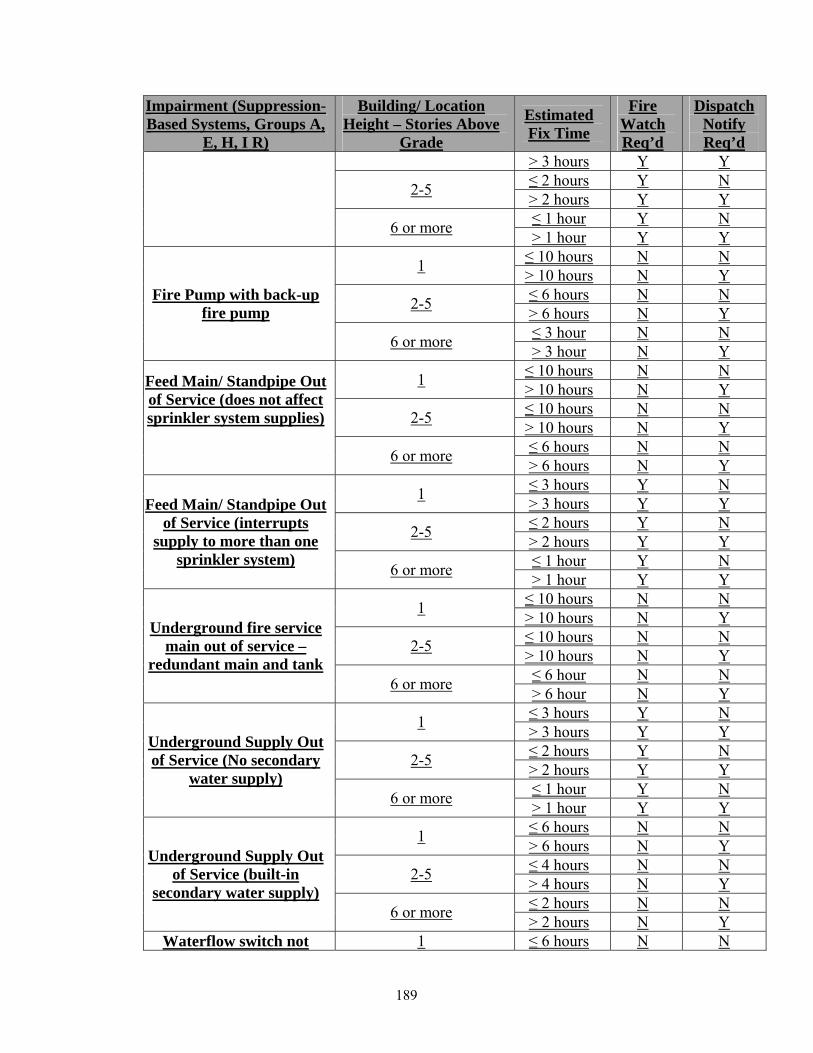
Impairment (Suppression-Based Systems, Groups A,
E, H, I R)
Building/ Location Height – Stories Above
Grade
Estimated Fix Time
Fire Watch Req’d
Dispatch Notify Req’d
> 3 hours Y Y ≤ 2 hours Y N 2-5 > 2 hours Y Y ≤ 1 hour Y N 6 or more > 1 hour Y Y ≤ 10 hours N N 1 > 10 hours N Y ≤ 6 hours N N 2-5 > 6 hours N Y ≤ 3 hour N N
Fire Pump with back-up fire pump
6 or more > 3 hour N Y ≤ 10 hours N N 1 > 10 hours N Y ≤ 10 hours N N 2-5 > 10 hours N Y ≤ 6 hours N N
Feed Main/ Standpipe Out of Service (does not affect sprinkler system supplies)
6 or more > 6 hours N Y
≤ 3 hours Y N 1 > 3 hours Y Y ≤ 2 hours Y N 2-5 > 2 hours Y Y ≤ 1 hour Y N
Feed Main/ Standpipe Out of Service (interrupts
supply to more than one sprinkler system) 6 or more > 1 hour Y Y
≤ 10 hours N N 1 > 10 hours N Y ≤ 10 hours N N 2-5 > 10 hours N Y ≤ 6 hour N N
Underground fire service main out of service –
redundant main and tank 6 or more > 6 hour N Y
≤ 3 hours Y N 1 > 3 hours Y Y ≤ 2 hours Y N 2-5 > 2 hours Y Y ≤ 1 hour Y N
Underground Supply Out of Service (No secondary
water supply) 6 or more > 1 hour Y Y
≤ 6 hours N N 1 > 6 hours N Y ≤ 4 hours N N 2-5 > 4 hours N Y ≤ 2 hours N N
Underground Supply Out of Service (built-in
secondary water supply) 6 or more > 2 hours N Y
Waterflow switch not 1 ≤ 6 hours N N
189
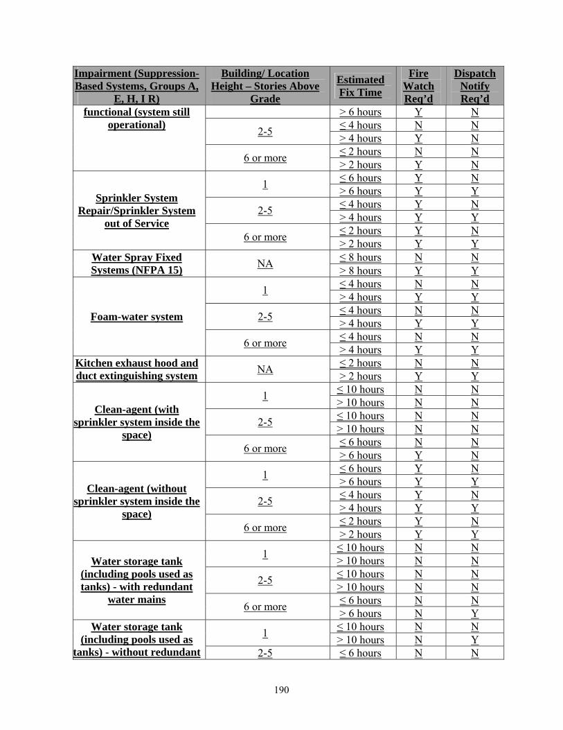
Impairment (Suppression-Based Systems, Groups A,
E, H, I R)
Building/ Location Height – Stories Above
Grade
Estimated Fix Time
Fire Watch Req’d
Dispatch Notify Req’d
> 6 hours Y N ≤ 4 hours N N 2-5 > 4 hours Y N ≤ 2 hours N N
functional (system still operational)
6 or more > 2 hours Y N ≤ 6 hours Y N 1 > 6 hours Y Y ≤ 4 hours Y N 2-5 > 4 hours Y Y ≤ 2 hours Y N
Sprinkler System Repair/Sprinkler System
out of Service 6 or more > 2 hours Y Y
≤ 8 hours N N Water Spray Fixed Systems (NFPA 15) NA > 8 hours Y Y
≤ 4 hours N N 1 > 4 hours Y Y ≤ 4 hours N N 2-5 > 4 hours Y Y ≤ 4 hours N N
Foam-water system
6 or more > 4 hours Y Y ≤ 2 hours N N Kitchen exhaust hood and
duct extinguishing system NA > 2 hours Y Y ≤ 10 hours N N 1 > 10 hours N N ≤ 10 hours N N 2-5 > 10 hours N N ≤ 6 hours N N
Clean-agent (with sprinkler system inside the
space) 6 or more > 6 hours Y N
≤ 6 hours Y N 1 > 6 hours Y Y ≤ 4 hours Y N 2-5 > 4 hours Y Y ≤ 2 hours Y N
Clean-agent (without sprinkler system inside the
space) 6 or more > 2 hours Y Y
≤ 10 hours N N 1 > 10 hours N N ≤ 10 hours N N 2-5 > 10 hours N N ≤ 6 hours N N
Water storage tank (including pools used as tanks) - with redundant
water mains 6 or more > 6 hours N Y ≤ 10 hours N N 1 > 10 hours N Y
Water storage tank (including pools used as
tanks) - without redundant 2-5 ≤ 6 hours N N
190

Impairment (Suppression-Based Systems, Groups A,
E, H, I R)
Building/ Location Height – Stories Above
Grade
Estimated Fix Time
Fire Watch Req’d
Dispatch Notify Req’d
> 6 hours N Y ≤ 3 hours N N
water mains and tank acts as secondary supply only 6 or more > 3 hours N Y
≤ 3 hours Y N 1 > 3 hours Y Y ≤ 2 hours Y N 2-5 > 2 hours Y Y ≤ 1 hours Y N
Water storage tank (including pools used as
tanks) - without redundant water mains and tank acts as break tank for primary
supply 6 or more > 1 hours Y Y ≤ 8 hours N N 1 > 8 hours Y Y ≤ 6 hours N N 2-5 > 6 hours Y Y ≤ 4 hours N N
Obstructions in water supply – Lack of
Flushing/MIC 6 or more > 4 hours Y Y
≤ 4 hours N N 1 > 4 hours Y Y ≤ 4 hours N N 2-5 > 4 hours Y Y ≤ 4 hours N N
Fire department access (fire hydrant, fire
command center, fire pump and FDC access) 6 or more > 4 hours Y Y
TABLE L102.1(b) FIRE-ALARM SYSTEMS – USE GROUPS A, E, H, I, R
Impairment (Fire Alarms Systems, Groups A, E, H, I, R)
Building Height - Stories Estimated Fix Time 1
Fire Watch Req’d
Dispatch Notify Req’d
≤ 3 hours Y N 1 > 3 hours Y Y ≤ 2 hours Y N 2-5 > 2 hours Y Y ≤ 1 hour Y N
Main FACU Not Operational (No Stand-alone Nodes)
6 or more > 1 hour Y Y ≤ 5 hours Y N 1 > 5 hours Y N ≤ 5 hours Y N 2-5 > 5 hours Y N
Main FACU Not Operational (Stand-alone Nodes are available)
6 or more ≤ 3 hours Y N
191
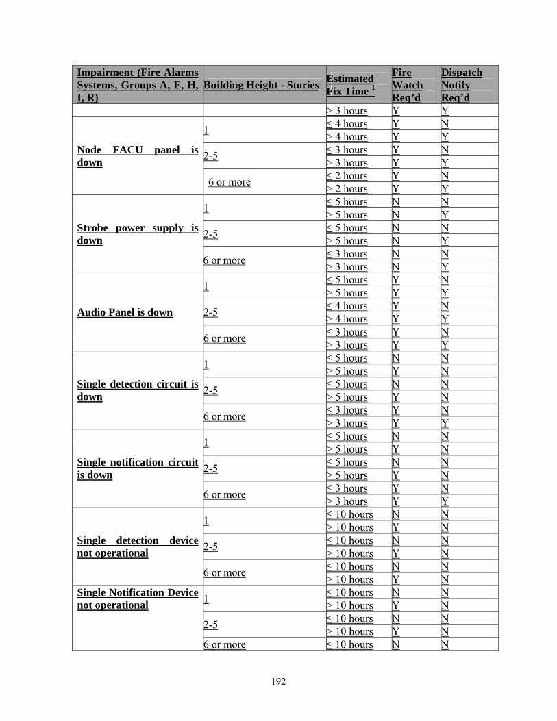
Impairment (Fire Alarms Systems, Groups A, E, H, I, R)
Building Height - Stories Estimated Fix Time 1
Fire Watch Req’d
Dispatch Notify Req’d
> 3 hours Y Y ≤ 4 hours Y N 1 > 4 hours Y Y ≤ 3 hours Y N 2-5 > 3 hours Y Y ≤ 2 hours Y N
Node FACU panel is down
6 or more > 2 hours Y Y ≤ 5 hours N N 1 > 5 hours N Y ≤ 5 hours N N 2-5 > 5 hours N Y ≤ 3 hours N N
Strobe power supply is down
6 or more > 3 hours N Y ≤ 5 hours Y N 1 > 5 hours Y Y ≤ 4 hours Y N 2-5 > 4 hours Y Y ≤ 3 hours Y N
Audio Panel is down
6 or more > 3 hours Y Y ≤ 5 hours N N 1 > 5 hours Y N ≤ 5 hours N N 2-5 > 5 hours Y N ≤ 3 hours Y N
Single detection circuit is down
6 or more > 3 hours Y Y ≤ 5 hours N N 1 > 5 hours Y N ≤ 5 hours N N 2-5 > 5 hours Y N ≤ 3 hours Y N
Single notification circuit is down
6 or more > 3 hours Y Y ≤ 10 hours N N 1 > 10 hours Y N ≤ 10 hours N N 2-5 > 10 hours Y N ≤ 10 hours N N
Single detection device not operational
6 or more > 10 hours Y N ≤ 10 hours N N 1 > 10 hours Y N ≤ 10 hours N N 2-5 > 10 hours Y N
Single Notification Device not operational
6 or more ≤ 10 hours N N
192
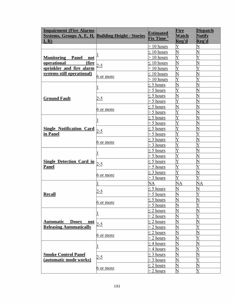
Impairment (Fire Alarms Systems, Groups A, E, H, I, R)
Building Height - Stories Estimated Fix Time 1
Fire Watch Req’d
Dispatch Notify Req’d
> 10 hours Y N ≤ 10 hours N N 1 > 10 hours Y Y ≤ 10 hours N N 2-5 > 10 hours Y Y ≤ 10 hours N N
Monitoring Panel not operational (fire sprinkler and fire alarm systems still operational) 6 or more > 10 hours Y Y
≤ 5 hours N N 1 > 5 hours Y N ≤ 5 hours N N 2-5 > 5 hours Y N ≤ 5 hours N N
Ground Fault
6 or more > 5 hours Y N ≤ 5 hours Y N 1 > 5 hours Y N ≤ 5 hours Y N 2-5 > 5 hours Y Y ≤ 3 hours Y N
Single Notification Card in Panel
6 or more > 3 hours Y Y ≤ 5 hours Y N 1 > 5 hours Y N ≤ 5 hours Y N 2-5 > 5 hours Y Y ≤ 3 hours Y N
Single Detection Card in Panel
6 or more > 3 hours Y Y 1 NA NA NA
≤ 5 hours N N 2-5 > 5 hours N Y ≤ 5 hours N N
Recall
6 or more > 5 hours N Y ≤ 2 hours N N 1 > 2 hours N Y ≤ 2 hours N N 2-5 > 2 hours N Y ≤ 2 hours N N
Automatic Doors not Releasing Automatically
6 or more > 2 hours N Y ≤ 4 hours N N 1 > 4 hours N Y ≤ 3 hours N N 2-5 > 3 hours N Y ≤ 2 hours N N
Smoke Control Panel (automatic mode works)
6 or more > 2 hours N Y
193

Impairment (Fire Alarms Systems, Groups A, E, H, I, R)
Building Height - Stories Estimated Fix Time 1
Fire Watch Req’d
Dispatch Notify Req’d
Smoke Control Panel (automatic mode does not works)
NA NA N Y
Fire fighter communication systems (fire phones and radio systems)
NA NA N Y
1 If the building is protected with a fire sprinkler system, the “Estimated Fix Time” hours shown in this column may be doubled.
L103 Impairment Tables – Use Groups B, F, M, S L103.1 Use Groups B, F, M, S. Groups B, F, M and S Occupancies are considered lower hazard occupancies. As such, the impairment guideline is tailored to manage the risks associated with those occupancies. Mitigation shall be in accordance with Table L103.1(a) and Table L103.1(b). TABLE L103.1(a) SUPPRESSION-BASED SYSTEMS – USE GROUPS B, F, M, S
Impairment (Water-Based Systems, Groups B, F, M
and S)
Building/ Location Height – Stories Above
Grade
Estimated Fix Time
Fire Watch Req’d
Dispatch Notify Req’d
≤ 10 hours Y N 1 > 10 hours Y Y ≤ 4 hours Y N 2-5 > 4 hours Y Y ≤ 2 hour Y N
Fire Pump
6 or more > 2 hour Y Y ≤ 10 hours N N 1 > 10 hours N Y ≤ 10 hours N N 2-5 > 10 hours N Y ≤ 10 hours N N
Fire Pump with back-up fire pump
6 or more > 10 hours N Y ≤ 10 hours N N Feed Main/ Standpipe Out
of Service (does not affect 1 > 10 hours N Y
194
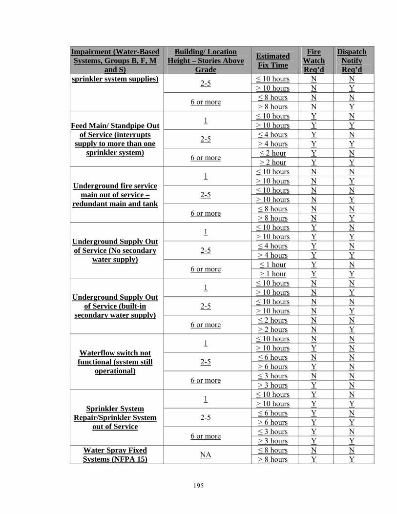
Impairment (Water-Based Systems, Groups B, F, M
and S)
Building/ Location Height – Stories Above
Grade
Estimated Fix Time
Fire Watch Req’d
Dispatch Notify Req’d
≤ 10 hours N N 2-5 > 10 hours N Y ≤ 8 hours N N
sprinkler system supplies) 6 or more > 8 hours N Y
≤ 10 hours Y N 1 > 10 hours Y Y ≤ 4 hours Y N 2-5 > 4 hours Y Y ≤ 2 hour Y N
Feed Main/ Standpipe Out of Service (interrupts
supply to more than one sprinkler system) 6 or more > 2 hour Y Y
≤ 10 hours N N 1 > 10 hours N Y ≤ 10 hours N N 2-5 > 10 hours N Y ≤ 8 hours N N
Underground fire service main out of service –
redundant main and tank 6 or more > 8 hours N Y
≤ 10 hours Y N 1 > 10 hours Y Y ≤ 4 hours Y N 2-5 > 4 hours Y Y ≤ 1 hour Y N
Underground Supply Out of Service (No secondary
water supply) 6 or more > 1 hour Y Y
≤ 10 hours N N 1 > 10 hours N Y ≤ 10 hours N N 2-5 > 10 hours N Y ≤ 2 hours N N
Underground Supply Out of Service (built-in
secondary water supply) 6 or more > 2 hours N Y
≤ 10 hours N N 1 > 10 hours Y N ≤ 6 hours N N 2-5 > 6 hours Y N ≤ 3 hours N N
Waterflow switch not functional (system still
operational) 6 or more > 3 hours Y N
≤ 10 hours Y N 1 > 10 hours Y Y ≤ 6 hours Y N 2-5 > 6 hours Y Y ≤ 3 hours Y N
Sprinkler System Repair/Sprinkler System
out of Service 6 or more > 3 hours Y Y
≤ 8 hours N N Water Spray Fixed Systems (NFPA 15) NA > 8 hours Y Y
195
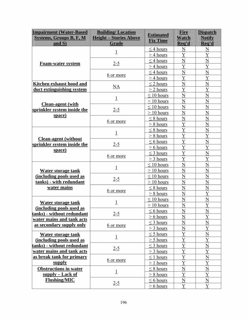
Impairment (Water-Based Systems, Groups B, F, M
and S)
Building/ Location Height – Stories Above
Grade
Estimated Fix Time
Fire Watch Req’d
Dispatch Notify Req’d
≤ 4 hours N N 1 > 4 hours Y Y ≤ 4 hours N N 2-5 > 4 hours Y Y ≤ 4 hours N N
Foam-water system
6 or more > 4 hours Y Y ≤ 2 hours N N Kitchen exhaust hood and
duct extinguishing system NA > 2 hours Y Y ≤ 10 hours N N 1 > 10 hours N N ≤ 10 hours N N 2-5 > 10 hours N N ≤ 8 hours N N
Clean-agent (with sprinkler system inside the
space) 6 or more > 8 hours Y N
≤ 8 hours Y N 1 > 8 hours Y Y ≤ 6 hours Y N 2-5 > 6 hours Y Y ≤ 3 hours Y N
Clean-agent (without sprinkler system inside the
space) 6 or more > 3 hours Y Y
≤ 10 hours N N 1 > 10 hours N N ≤ 10 hours N N 2-5 > 10 hours N N ≤ 8 hours N N
Water storage tank (including pools used as tanks) - with redundant
water mains 6 or more > 8 hours N Y ≤ 10 hours N N 1 > 10 hours N Y ≤ 6 hours N N 2-5 > 6 hours N Y ≤ 3 hours N N
Water storage tank (including pools used as
tanks) - without redundant water mains and tank acts as secondary supply only 6 or more > 3 hours N Y
≤ 5 hours Y N 1 > 5 hours Y Y ≤ 3 hours Y N 2-5 > 3 hours Y Y ≤ 1 hours Y N
Water storage tank (including pools used as
tanks) - without redundant water mains and tank acts as break tank for primary
supply 6 or more > 1 hours Y Y ≤ 8 hours N N 1 > 8 hours Y Y ≤ 6 hours N N
Obstructions in water supply – Lack of
Flushing/MIC 2-5 > 6 hours Y Y
196

Impairment (Water-Based Systems, Groups B, F, M
and S)
Building/ Location Height – Stories Above
Grade
Estimated Fix Time
Fire Watch Req’d
Dispatch Notify Req’d
≤ 4 hours N N 6 or more > 4 hours Y Y ≤ 4 hours N N 1 > 4 hours Y Y ≤ 4 hours N N 2-5 > 4 hours Y Y ≤ 4 hours N N
Fire department access (fire hydrant, fire
command center, fire pump and FDC access) 6 or more > 4 hours Y Y
197
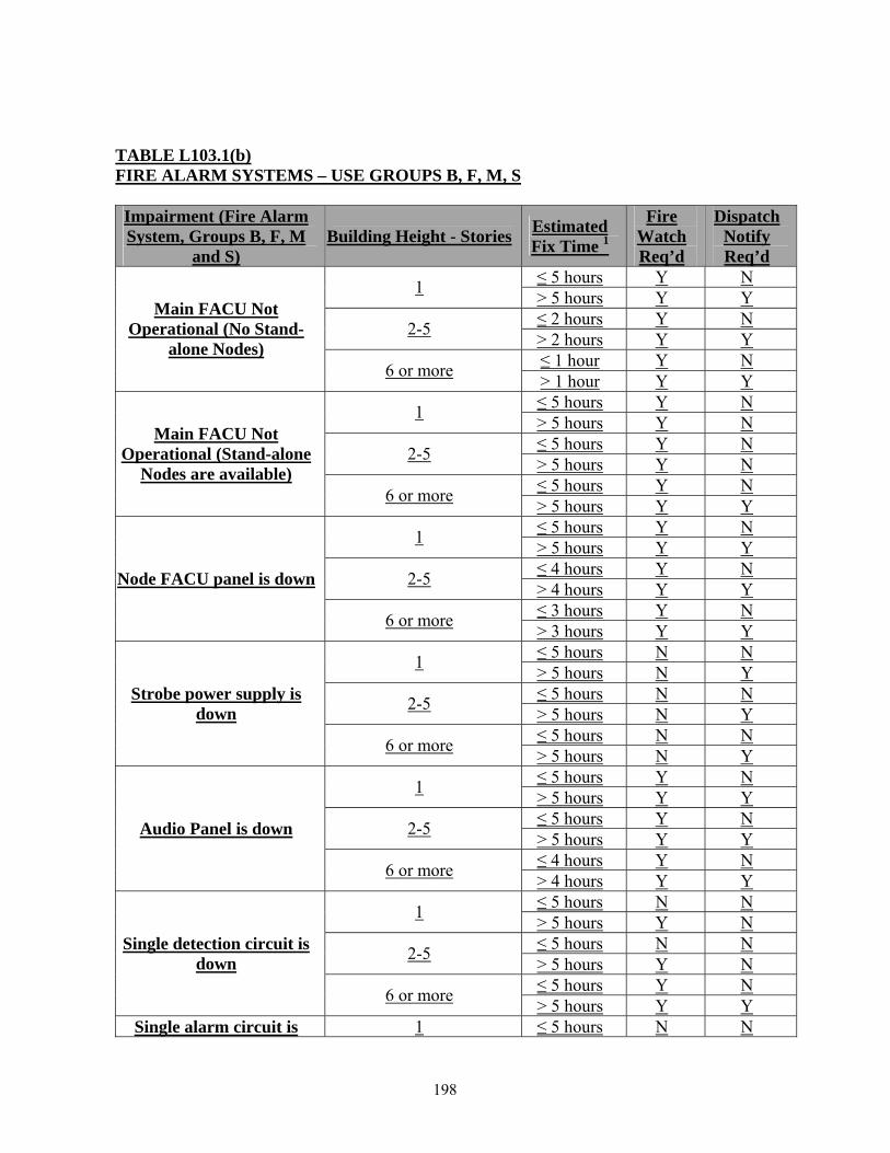
TABLE L103.1(b) FIRE ALARM SYSTEMS – USE GROUPS B, F, M, S
Impairment (Fire Alarm System, Groups B, F, M
and S) Building Height - Stories Estimated
Fix Time 1
Fire Watch Req’d
Dispatch Notify Req’d
≤ 5 hours Y N 1 > 5 hours Y Y ≤ 2 hours Y N 2-5 > 2 hours Y Y ≤ 1 hour Y N
Main FACU Not Operational (No Stand-
alone Nodes) 6 or more > 1 hour Y Y
≤ 5 hours Y N 1 > 5 hours Y N ≤ 5 hours Y N 2-5 > 5 hours Y N ≤ 5 hours Y N
Main FACU Not Operational (Stand-alone
Nodes are available) 6 or more > 5 hours Y Y
≤ 5 hours Y N 1 > 5 hours Y Y ≤ 4 hours Y N 2-5 > 4 hours Y Y ≤ 3 hours Y N
Node FACU panel is down
6 or more > 3 hours Y Y ≤ 5 hours N N 1 > 5 hours N Y ≤ 5 hours N N 2-5 > 5 hours N Y ≤ 5 hours N N
Strobe power supply is down
6 or more > 5 hours N Y ≤ 5 hours Y N 1 > 5 hours Y Y ≤ 5 hours Y N 2-5 > 5 hours Y Y ≤ 4 hours Y N
Audio Panel is down
6 or more > 4 hours Y Y ≤ 5 hours N N 1 > 5 hours Y N ≤ 5 hours N N 2-5 > 5 hours Y N ≤ 5 hours Y N
Single detection circuit is down
6 or more > 5 hours Y Y Single alarm circuit is 1 ≤ 5 hours N N
198

Impairment (Fire Alarm System, Groups B, F, M
and S) Building Height - Stories Estimated
Fix Time 1
Fire Watch Req’d
Dispatch Notify Req’d
> 5 hours Y N ≤ 5 hours N N 2-5 > 5 hours Y N ≤ 5 hours Y N
down
6 or more > 5 hours Y Y ≤ 10 hours N N 1 > 10 hours Y N ≤ 10 hours N N 2-5 > 10 hours Y N ≤ 10 hours N N
Single detection device not operational
6 or more > 10 hours Y N ≤ 10 hours N N 1 > 10 hours Y N ≤ 10 hours N N 2-5 > 10 hours Y N ≤ 10 hours N N
Single Notification Device not operational
6 or more > 10 hours Y N ≤ 10 hours N N 1 > 10 hours Y Y ≤ 10 hours N N 2-5 > 10 hours Y Y ≤ 10 hours N N
Monitoring Panel not operational (fire sprinkler and fire alarm systems still
operational) 6 or more > 10 hours Y Y ≤ 10 hours N N 1 > 10 hours Y N ≤ 10 hours N N 2-5 > 10 hours Y N ≤ 10 hours N N
Ground Fault
6 or more > 10 hours Y N ≤ 5 hours Y N 1 > 5 hours Y N ≤ 5 hours Y N 2-5 > 5 hours Y Y ≤ 3 hours Y N
Single Notification Card in Panel
6 or more > 3 hours Y Y ≤ 5 hours Y N 1 > 5 hours Y N ≤ 5 hours Y N 2-5 > 5 hours Y Y ≤ 3 hours Y N
Single Detection Card in Panel
6 or more > 3 hours Y Y Recall 1 NA NA NA
199
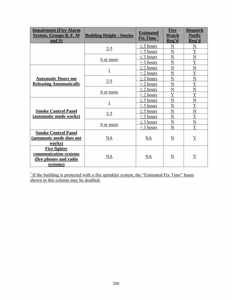
Impairment (Fire Alarm System, Groups B, F, M
and S) Building Height - Stories Estimated
Fix Time 1
Fire Watch Req’d
Dispatch Notify Req’d
≤ 5 hours N N 2-5 > 5 hours N Y ≤ 3 hours N N 6 or more > 3 hours N Y ≤ 2 hours N N 1 > 2 hours N Y ≤ 2 hours N N 2-5 > 2 hours N Y ≤ 2 hours N N
Automatic Doors not Releasing Automatically
6 or more > 2 hours Y Y ≤ 5 hours N N 1 > 5 hours N Y ≤ 5 hours N N 2-5 > 5 hours N Y ≤ 3 hours N N
Smoke Control Panel (automatic mode works)
6 or more > 3 hours N Y Smoke Control Panel
(automatic mode does not works)
NA NA N Y
Fire fighter communication systems (fire phones and radio
systems)
NA NA N Y
1 If the building is protected with a fire sprinkler system, the “Estimated Fix Time” hours shown in this column may be doubled.
200