c)l~...march 21,2018 - 3 - analysis the dike master plan is intended to be a comprehensive guide to...
TRANSCRIPT

To:
From:
City of Richmond
Public Works and Transportation Committee
John Irving, P.Eng. MPA Director, Engineering
Re: Dike Master Plan - Phase 2 Report
Staff Recommendation
Report to Committee
Date: March 21, 2018
File: 10-6045-09-01/2018-Vol 01
1. That the existing dike alignment in the Dike Master Plan Phase 2 study area (West Dike from Williams Road to Tetra Nova and North Dike from Tena Nova to No.6 Road) continue to be the primary flood protection dike alignment.
2. That the work plan identified in the staff repmi titled Dike Master Plan- Phase 2 Report from the Director ofEngineering, dated March 21,2018, be endorsed.
C)L~ John Irving, P.Eng. MPA Director, Engineering (604-276-4140)
Art. 1
ROUTED TO:
Real Estate Services Roads and Construction Sewerage and Drainage Parks Development Applications Policy Planning Transportation
REVIEWED BY STAFF REPORT I AGENDA REVIEW SUBCOMMITTEE
5733629
REPORT CONCURRENCE
CONCURRENCE CO~NCE OF GENERAL MANAGER
~ (~
~ ~ ~
INITIALS: vtDBY~O ~1 !d
~
CNCL - 242
March 21, 2018 - 2-
Staff Report
Origin
By the year 2100, climate change scientists estimate that sea level will rise approximately 1.0 meter and the City will subside 0.2 meters. To maintain Richmond's high level of :flood protection, the City will need to increase the height of the City's dikes by 1.2 mover the next 25 to 75 years.
The 2008 - 2031 Richmond Flood Protection Strategy identified the need to "Prepare and implement a comprehensive dike improvement program." On February 11, 2014, Council approved $200,000 from the 2014 Capital Budget to prepare Dike Master Plan Phase 2.
The Dike Master Plan Phase 2 Draft Report was presented at the regular Council meeting on January 26, 2017, where Council resolved:
"That the public and key external stakeholders be consulted to provide feedback on the medium and long term dike improvements required for part of Richmond's West Dike (betvveen Williams Road and Terra Nova Rural Park) and part of the North Dike (betvveen Terra Nova Rural Park to No. 6 Road) as identified in the staff report titled "Dike Master Plan- Phase 2 "from the Director of Engineering, dated December 6, 2016."
Staff have completed stakeholder consultation for Dike Master Plan Phase 2 and the results of that consultation are the focus of this report.
This report supports the following Council2014-2018 Term Goals:
5733629
#5 Partnerships and Collaboration:
Continue development and utilization of collaborative approaches and partnerships with intergovernmental and other agencies to help meet the needs of the Richmond community.
5.2. Strengthened strategic partnerships that help advance City priorities.
#6 Quality Infrastructure Networks:
Continue diligence towards the development of inji-astructure netlvorks that are safe, sustainable, and address the challenges associated with aging systems, population growth, and environmental impact.
6.1. Safe and sustainable infrastructure.
#9 A Well-Informed Citizenry:
Continue to develop and provide programs and services that ensure the Richmond community is well-informed and engaged on City business and decision making.
9. 2. Effective engagement strategies and tools.
CNCL - 243

March 21,2018 - 3 -
Analysis
The Dike Master Plan is intended to be a comprehensive guide to upgrade the City's dikes to:
• Protect Richmond from both ocean stmm surges and Fraser River freshet events;
• Adapt to sea level rise and land subsidence;
• Be seismically resilient;
• Integrate the Ecological Network Management Strategy principles and goals;
• Follow the five strategic directions of the City's 2009 Waterfront Strategy; and
• Prioritize dike improvement phasing to efficiently use resources.
The cunent phases of the Dike Master Plan are shown in Attachment 1. Phase 1 is complete and was endorsed by Council on April 22, 2013. Stakeholder consultation for the draft version of Phase 2 is complete and is the focus of this repmi. National Disaster Mitigation Program grant funding was secured for Phase 3 and work was defened from an original March 2017 stmi date to November 2017 to meet the funding conditions ofthe grant. Work on Phase 4 ofthe Dike Master Plan began in October 2017. Staff anticipate that both Phase 3 and Phase 4 will be completed in 2018. Staff recently secured a $150,000 grant from the Union ofBC Municipalities Community Prepm·edness Fund for Phase 5 ofthe Dike Master Plan and work will begin in 2018.
Dike Master Plan Phase 2 focusses on the north pmiion of Richmond's West Dike between Williams Road and Tena Nova Rural Park and part of Richmond's North Dike between Tena Nova Rural Park and No.6 Road (Phase 2 Study Area), as shown in Figure 1. The Dike Master Plan Phase 2 Repmi is appended as Attachment 2.
Figure 1 - Dike Master Plan Phase 2 Study Area
\' c.:~
LEGEI4D
5733629 CNCL - 244

March 21, 2018 - 4 -
Public Feedback
Dike Master Plan Phase 2 was presented to the public through two open houses and the City's Let's Talk Richmond web site. Approximately 200 people attended the open houses and 532 people visited the web page. Two people submitted written comments at the open houses and 68 people completed an online survey.
Based on feedback received, the public indicated:
• general acceptance that climate change is real;
• support for ongoing sea level monitoring;
• support for dike master planning and dike raising;
• support for coordination with development to create super dikes;
• support for the creation of barrier islands on Sturgeon Banks;
• support for flood construction levels;
• support for consideration of environmental impacts in the Dike Master Plan;
• concern regarding the uncertainty in sea level rise forecasting and support for building dikes higher than the currently proposed levels;
• that the dike trail network is an important amenity. Of those that expressed a preference, 70% preferred a more natural trail integrated with the surrounding environment and 30% preferred a paved, "Sea Wall" type trail. The 2010 Richmond Trail Strategy guides the City in trail development and will be incorporated into all of the City's dike improvement projects; and
• that they would like more information regarding the amount of capital assigned to dike improvements and the timing of dike upgrades. Council has approved the 2018 to 2022 Drainage and Diking Capital plan which includes $5 million in dike upgrade every year for the next five years. Staff will continue to inform the public on the timing and funding of the projects through capital open houses, the City's website and infmmation in utility inserts.
Key External Stakeholder Feedback
Key external stakeholders consulted included:
• Department of Fisheries and Oceans
• Provincial Inspector of Dikes
• Ducks Unlimited Canada
• The City's Advisory Committee for the Environment
5733629 CNCL - 245

March 21, 2018 - 5 -
• The City's Heritage Commission
• The Urban Development Institute
• Fraser Basin Council
• P01i Metro Vancouver
Stakeholders that returned comments were generally supportive of the findings in Dike Master Plan Phase 2.
The Department of Fisheries and Oceans - Small Craft Harbours indicated they are considering options that restore intertidal sediment supply to Sturgeon Banks as part of an overall sediment management plan. They expressed concerns regarding the banier islands concept based on a possibility that tidal flood and storm cunents could cause gullying of tidal flat sediments around the proposed batTier islands.
The Provincial Inspector of Dikes indicated that Dike Master Plan Phase 2 is a reasonable plan, but indicated that any "unconventional" strategies would require further consultation with the Province.
The City's Heritage Commission indicated supp01i for Dike Master Plan Phase 2 and recommended that the City incorporate the cultural and historical aspects of the diking system into diking improvements.
The Urban Development Institute stated in writing that Dike Master Plan Phase 2 will mutually benefit the City of Richmond and UDI members as the design for specialized flood protection along the waterfront will increase the livability and value of large developments by increasing flood protection.
Next Steps
Dike Master Plan Phase 2 identifies a long term program for dike improvements from Williams Road to No.6 Road over the next 25 to 75 years to stay ahead of climate change induced sea level rise and land subsidence. Funding for dike improvements is secured through the Drainage and Diking Utility which cunently collect $11.6 million annually through utility rates for drainage and diking capital projects.
As sea level rise is realized, the rate of dike improvement will be adjusted accordingly. Staff will present annual utility funding levels for dike improvement for Council's consideration through the bi-annual Ageing Infrastructure Report. Upgrades will also occur in conjunction with the City's growth, allowing synergies between the City and the development community. In the short and medium term, there is a significant amount of work that can be carried out in preparation for these upgrades. Should Council endorse this work plan, staff will:
• Investigate the application ofbanier islands and the impacts to habitat for the Sturgeon Bank area. Coordinate these actions with other jurisdictions that have interests in Sturgeon Bank;
• Encourage the construction of superdikes through development;
5733629 CNCL - 246

March 21,2018 - 6 -
• Re-evaluate current and future flood construction levels and development bylaws to reduce flood risk;
• Strategically acquire property in support of future dike upgrading;
• Monitor sea level rise using water level sensors; and
• Investigate creation of a habitat banking program to support dike improvement projects based on environmental assessment.
Financial Impact
Capital projects will be brought forward for Council's consideration as part of the Council budget process.
Conclusion
Consistent with the City' s 2008 - 2031 Richmond Flood Protection Strategy, Dike Master Plan Phase 2 identifies medium and long term dike improvements along part of the West Dike (Williams Road to Ten-a Nova Rural Park) and part of the North Dike (Terra Nova Rural Park to No. 6 Road) that will be required to address climate change induced sea level rise. Dike Master Plan Phase 2 generally recommends that the City maintain the existing dike alignments in the study area, pursue superdikes through development, and investigate wave mitigating banier islands on Sturgeon Banks.
Public and key stakeholder feedback on Dike Master Plan Phase 2 is positive and will be incorporated into capital dike improvement projects identified in this plan.
Lloy Bie, flg· Man ger, Engineering Planning (604-276-4075)
LB:pm
Att. 1: Dike Master Plan Phasing Map
iJI?2/;tn711-11'/t laAN.J
Pratima Milaire, P .Eng. Project Engineer, Engineering Planning (604-276-4039)
Att. 2: Dike Master Plan Phase 2 Final Report 2018'
5733629 CNCL - 247

....
R:\
Eng
inee
ring
Pla
nn
ing
\Sh
are
d\P
roje
cts\
Oyk
es\p
df\
Dik
e_
Pro
ject
_H
isto
ry.p
df
Leg
end
-P
hase
1
Pha
se 2
-
Pha
se 3
-
Ph
ase
4
-P
hase
5
e P
ump
Sta
tion
Upg
rade
s
-' C
urre
nt D
ike
Impr
ovem
ent
Pro
ject
s
11
" P
roje
cts
in 2
018
Cap
ital
Pro
gram
No
te:
The
in
fon
ufi
..,
ohow
n on
thi
o m
•p i
t co
mpi
led
fro
m,·
ori
ou
oo
ou
rceo
.nd
thcC
itrm
•l.:
nn
o
WD
ITII
nti
o:o
.cx
pn
:llc
do
rim
pli
cd
.nlo
thco
ccu
ncr
.,.e
um
plc
tcn
ctl
oft
he
infe
>rm
nlio
n.
lfo
cnn
rcrc
mim
kd
thm
tlo
tliz
eo a
nd l
egal
d
ncr
ipti
on
mU
ith
c co
nfu
med
ntt
hcL
mn
d T
ille
of
Toce
in NcwWcttminl~r
.
Thi
o!S
NO
T•I
c;D
I do
xum
cnL
and
is
publ
ilhe
d fO
I'" in
form
atio
n •n
d c
onve
nien
ce Jl
"fl""
"" o
n]~·
. C
Ci~
· o
f R
ichm
ond.
. :!:0
17.
All
righ
a: r
cocr
vcd.
Nott~bcrcpTOduccdordiotn"but
cdwi
thou
t pe
nn in
ion
.
;." .0",;
::",;;,~---
';;o;·':.'.,..
...
NO
RTH
Pri
Jted
Oat
e:N
ove
mb
er9
,201
7
R:\
Eng
inee
ring
Pla
nn
ing
\Sh
are
d\P
roje
cts\
Oyk
es\
mxd
\Oik
e_
Pro
ject
_H
isto
rym
xd
~
::+
~ 8 (1) a >--
'
CNCL - 248
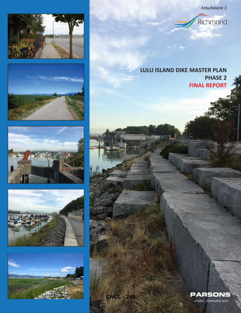
Parsons475287 - FEBRUARY 2018
LULU ISLAND DIKE MASTER PLANPHASE 2
FINAL REPORT
Attachment 2
CNCL - 249
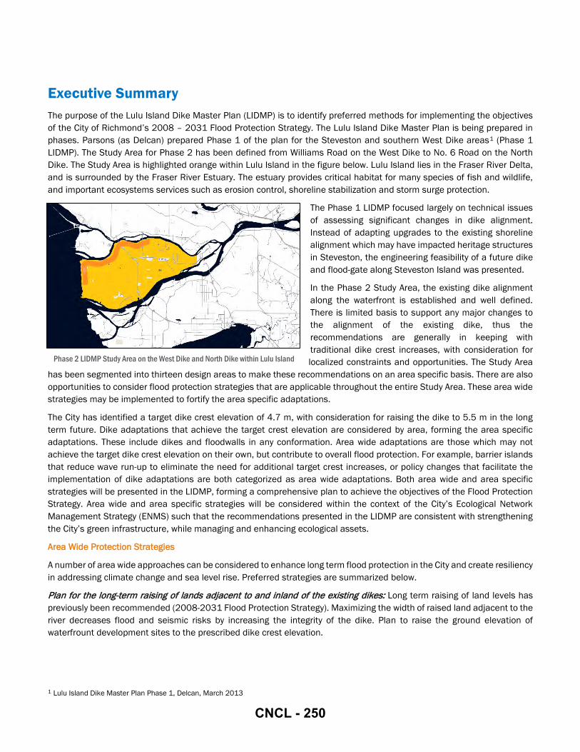
Executive Summary The purpose of the Lulu Island Dike Master Plan (LIDMP) is to identify preferred methods for implementing the objectives of the City of Richmond’s 2008 – 2031 Flood Protection Strategy. The Lulu Island Dike Master Plan is being prepared in phases. Parsons (as Delcan) prepared Phase 1 of the plan for the Steveston and southern West Dike areas1 (Phase 1 LIDMP). The Study Area for Phase 2 has been defined from Williams Road on the West Dike to No. 6 Road on the North Dike. The Study Area is highlighted orange within Lulu Island in the figure below. Lulu Island lies in the Fraser River Delta, and is surrounded by the Fraser River Estuary. The estuary provides critical habitat for many species of fish and wildlife, and important ecosystems services such as erosion control, shoreline stabilization and storm surge protection.
The Phase 1 LIDMP focused largely on technical issues of assessing significant changes in dike alignment. Instead of adapting upgrades to the existing shoreline alignment which may have impacted heritage structures in Steveston, the engineering feasibility of a future dike and flood-gate along Steveston Island was presented.
In the Phase 2 Study Area, the existing dike alignment along the waterfront is established and well defined. There is limited basis to support any major changes to the alignment of the existing dike, thus the recommendations are generally in keeping with traditional dike crest increases, with consideration for localized constraints and opportunities. The Study Area
has been segmented into thirteen design areas to make these recommendations on an area specific basis. There are also opportunities to consider flood protection strategies that are applicable throughout the entire Study Area. These area wide strategies may be implemented to fortify the area specific adaptations.
The City has identified a target dike crest elevation of 4.7 m, with consideration for raising the dike to 5.5 m in the long term future. Dike adaptations that achieve the target crest elevation are considered by area, forming the area specific adaptations. These include dikes and floodwalls in any conformation. Area wide adaptations are those which may not achieve the target dike crest elevation on their own, but contribute to overall flood protection. For example, barrier islands that reduce wave run-up to eliminate the need for additional target crest increases, or policy changes that facilitate the implementation of dike adaptations are both categorized as area wide adaptations. Both area wide and area specific strategies will be presented in the LIDMP, forming a comprehensive plan to achieve the objectives of the Flood Protection Strategy. Area wide and area specific strategies will be considered within the context of the City’s Ecological Network Management Strategy (ENMS) such that the recommendations presented in the LIDMP are consistent with strengthening the City’s green infrastructure, while managing and enhancing ecological assets.
Area Wide Protection Strategies
A number of area wide approaches can be considered to enhance long term flood protection in the City and create resiliency in addressing climate change and sea level rise. Preferred strategies are summarized below.
Plan for the long-term raising of lands adjacent to and inland of the existing dikes: Long term raising of land levels has previously been recommended (2008-2031 Flood Protection Strategy). Maximizing the width of raised land adjacent to the river decreases flood and seismic risks by increasing the integrity of the dike. Plan to raise the ground elevation of waterfrount development sites to the prescribed dike crest elevation.
1 Lulu Island Dike Master Plan Phase 1, Delcan, March 2013
Phase 2 LIDMP Study Area on the West Dike and North Dike within Lulu Island
CNCL - 250

Enhance floodproofing through amendments to the FCL By-law: The City’s Flood Construction Level (FCL) Bylaw establishes minimum levels to which land needs to be raised. Amending the FCL bylaw is the recommended area wide strategy to regulate raising ground elevations with redevelopment to improve flood protection throughout the Study Area.
Support site assemblies along the waterfront that promote cohesive adaptations for flood protection: Large developments along the waterfront allow for major improvements to flood protection infrastructure and often result in robust superdike conditions.
Plan for implementation of offshore protection on Sturgeon Banks: If climate change and sea level rise predictions materialize, increased depths offshore could simultaneously increase wave heights, particularly in the Georgia Strait. Upland limitations to natural accretion within the Sturgeon Bank Wildlife Management Area may also contribute to increased offshore depths beyond the West Dike. Offshore barrier islands are one option to consider to dissipate wave energy prior to waves reaching the West Dike and stabilize shorelines, thereby minimizing future dike crest increases. Enhancement of intertidal habitat alongside the creation of offshore barrier islands may provide natural ecosystem mechanisms to further dissipate wave energy. The City may consider offshore protection in its long-term plans for flood protection along the West Dike.
Area Specific Flood Protection Strategies
In practice, when dike upgrades have been made, they have been made along the existing alignment. Apart from select site specific constraints and opportunities, the recommended future dike alignment for the Phase 2 Study Area matches the existing dike alignment. Area specific strategies were selected with consideration for: flood protection, environmental, geotechnical, infrastructure, site-specific constraints, social, property, economic, operational and cost considerations. The City is committed to avoid, mitigate or compensate for any environmental impacts that may result from dike adaptation projects. Completely avoiding any impact on an environmental area may not be feasible in some cases, for example where dikes are highly constrained. In these instances, mitigation or compensation that follows a net gain approach may be pursued.
Area specific strategies for the Phase 2 study are summarized below:
West Dike: Raise the dike on the existing alignment. Additional studies required to quantify drainage impacts of land side expansion, habitat impacts and costs associated with water side or land side expansion, and long term resiliency of a constrained dike solution. Consider routing the dike inland through Terra Nova Rural Park.
North Dike: Terra Nova to No. 2 Road Bridge: Raise the dike on the existing alignment with land side expansion. Plan for the raising of River Road.
North Dike: No. 2 Road Bridge to Dinsmore Bridge: Existing and proposed developments are raising elevations to 4.0 m to 4.7 m. Future raisings to 5.5 m can take place on the existing alignments and integrate into the adjacent landscaping.
North Dike: Dinsmore Bridge to Moray Bridge: Raise the dike with land side expansion. Consider creation of a set-back dike and inland raising (superdike) in conjunction with the future Middle Arm Waterfront Park construction. Ensure any interim dike upgrades are compatible with the long term strategy of constructing superdikes.
North Dike: Moray Bridge to Oak Street Bridge: Implement flood protection with approved development plans for Duck Island and the River Rock Casino when available. If required to address sea level rise and climate change prior to implementation of the approved strategy at the Duck Island or River Rock Casino sites, plan for a temporary adaptation, such as a demountable floodwall, to protect City assets
North Dike: Oak Street Bridge to No. 4 Road: Raise the dike on the existing alignment. Site specific solutions may be required at the Fraser River Terminal site. Plan for temporary dike along the alternate alignment if required to address sea level rise and climate change prior to implementation of a strategy at the Fraser River Terminal site.
North Dike: No. 4 Road to Shell Road: Existing and proposed developments will raise the area generally to an elevation of 4.7 m. Future raisings to 5.5 m can take place on the existing alignments and integrate into the adjacent landscaping.
North Dike: Shell Road to No. 6 Road: Raise the dike on the existing alignment. Land acquisition may be required to facilitate construction of a trapezoidal dike (through redevelopment or otherwise). Implementation of a temporary floodwall
CNCL - 251

adjacent to the waterfront lots may be required in advance of a permanent adaptation to address sea level rise and climate change. Consider Bath Slough Revitalization Initiative for future designs. Additional studies are required to quantify drainage, habitat impacts, and costs associated with land side expansion of a trapezoidal dike. A constrained land side slope may be required to integrate with the existing drainage infrastructure.
CNCL - 252
Table of Contents
EXECUTIVE SUMMARY.................................................................................................................................................................... I
1 INTRODUCTION ..................................................................................................................................................................... 1
1.1 SCOPE ........................................................................................................................................................................... 2
1.2 APPROACH .................................................................................................................................................................... 2
1.3 ADDITIONAL GUIDANCE DOCUMENTS ........................................................................................................................ 2
2 STUDY AREA .......................................................................................................................................................................... 3
2.1 PRESENT AND FUTURE LAND USE .............................................................................................................................. 5
2.2 GEOTECHNICAL CONDITIONS ...................................................................................................................................... 6
2.3 ENVIRONMENTAL CONDITIONS .................................................................................................................................. 7
2.4 EXISTING FLOOD PROTECTION INFRASTRUCTURE ..................................................................................................10
2.5 EXISTING FLOOD PROTECTION POLICY ....................................................................................................................11
3 CONSIDERATIONS ...............................................................................................................................................................11
3.1 FLOOD PROTECTION CONSIDERATIONS ...................................................................................................................11
3.2 ENVIRONMENTAL CONSIDERATIONS .......................................................................................................................12
3.3 GEOTECHNICAL CONSIDERATIONS ...........................................................................................................................12
3.4 INFRASTRUCTURE CONSIDERATIONS ......................................................................................................................14
3.5 SITES WITH UNIQUE CONSTRAINTS ..........................................................................................................................15
3.6 SOCIAL CONSIDERATIONS .........................................................................................................................................15
3.7 PROPERTY CONSIDERATIONS ...................................................................................................................................15
3.8 ECONOMIC CONSIDERATIONS ..................................................................................................................................16
3.9 OPERATIONAL CONSIDERATIONS .............................................................................................................................16
3.10 COST CONSIDERATIONS ............................................................................................................................................16
3.11 STAKEHOLDER FEEDBACK ........................................................................................................................................16
4 FLOOD RISK MANAGEMENT ADAPTATIONS ......................................................................................................................20
4.1 AREA WIDE ADAPTATIONS .........................................................................................................................................21
4.1.1 Superdikes ........................................................................................................................................................21
4.1.2 Flood Proofing ...................................................................................................................................................22
4.1.3 Planning and Development Controls ...............................................................................................................24
4.1.4 Breakwaters and Barrier Islands ......................................................................................................................24
4.1.5 Secondary Dikes ...............................................................................................................................................26
4.2 AREA SPECIFIC ADAPTATIONS ...................................................................................................................................28
CNCL - 253

4.2.1 Seafair ...............................................................................................................................................................30
4.2.2 Terra Nova .........................................................................................................................................................31
4.2.3 Thompson Terra Nova .......................................................................................................................................32
4.2.4 Thompson Dover ...............................................................................................................................................33
4.2.5 Oval ....................................................................................................................................................................34
4.2.6 City Centre 1 ......................................................................................................................................................35
4.2.7 City Centre 2 ......................................................................................................................................................36
4.2.8 Duck Island ........................................................................................................................................................37
4.2.9 Industrial ............................................................................................................................................................38
4.2.10 Bridgeport Tait ...................................................................................................................................................39
4.2.11 Industrial North East 1 ......................................................................................................................................40
4.2.12 Industrial North East 2 ......................................................................................................................................41
4.2.13 Industrial North East 3 ......................................................................................................................................42
4.3 SITE SPECIFIC ADAPTATIONS ....................................................................................................................................43
4.3.1 Bridges ...............................................................................................................................................................43
4.3.2 Raise River Road ...............................................................................................................................................44
5 TIMING OF ADAPTATION PROJECTS ...................................................................................................................................45
5.1 REDEVELOPMENT OF SMALL LOTS ..........................................................................................................................46
5.2 LAND ACQUISITIONS & LEGAL ACCESS ....................................................................................................................46
5.3 RAISING THE TARGET DIKE CREST ELEVATION .......................................................................................................46
5.4 INTERIM ADAPTATIONS .............................................................................................................................................46
6 IMPLEMENTATION OPPORTUNITIES ..................................................................................................................................47
6.1 WATERFRONT TRAIL SYSTEM ...................................................................................................................................47
6.2 INTERTIDAL ZONES ....................................................................................................................................................48
6.3 HABITAT BANKING .....................................................................................................................................................48
7 RECOMMENDATIONS .........................................................................................................................................................48
CNCL - 254

List of Figures
Figure 1 Study Area Figure 2 Design Areas and OCP Boundaries Figure 3 Riparian Management Areas (RMA’s) Figure 4 Foreshore Habitat Coding in the Study Area Figure 5 Superdikes in the Study Area Figure 6 Flood Construction Levels (FCL’s) Figure 7 Artistic Rendering of Barrier Island Concept for Sturgeon Bank Figure 8 Secondary Dike Alignment through Terra Nova Figure 9 2006 Concept Plan for the Proposed Middle Arm Park Figure 10 Bridges in the Study Area Figure 11 Raising River Road in the Thompson Neighbourhood List of Tables
Table 1 Summary of Existing and Future Conditions Table 2 Public Consultation Feedback Table 3 Other Key Stakeholder Feedback Table 4 Recommended Flood Risk Management Strategies Table 5 Recommended Area Specific Adaptations Table 6 Bridge Constraints and Recommended Adaptations Table 7 Triggers to Implementation of Adaptations List of Appendices
Appendix A Official Community Plan Maps Appendix B Riparian Management Areas Appendix C Environmentally Sensitive Areas Appendix D Ecological Network Strategy Areas Appendix E Habitat Coding Maps Appendix F Typical Dike Cross Sections List of Attachments
Attachment 1 Technical Memo #1 – Parsons Attachment 2 Technical Memo #2 – Parsons Attachment 3 Geotechnical Input Memo – Thurber Attachment 4 Environmental Technical Brief – Envirowest Attachment 5 Seismic Deformation Analysis – Thurber
CNCL - 255

1 Introduction Richmond is a city of over 200,000 people in 130 square kilometres with considerable assets to be protected from flood damage. The City has endeavoured to adapt its flood protection systems to changing flood risks, including anticipated increases to flood levels resulting from climate change and sea level rise. With the establishment of the 2008 – 2031 Flood Protection Strategy, the City committed to prepare and implement a perimeter dike improvement program. The purpose of the Lulu Island Dike Master Plan (LIDMP) is to identify preferred methods for implementing the objectives of the City of Richmond’s 2008 – 2031 Flood Protection Strategy.
With Richmond located at the mouth of the Fraser River, and the flood protection infrastructure interfacing with the high ecological value of the Fraser River Estuary, the LIDMP also works to integrate the objectives of key City documents such as the City’s Ecological Network Management Strategy (ENMS), and put forward recommendations that will strengthen the City’s green infrastructure network.
The LIDMP is being prepared in phases. Parsons (as Delcan) prepared Phase 1 of the LIDMP for the Steveston and southern West Dike areas2 (Phase 1 LIDMP). The Study Area for the second phase of the LIDMP (Phase 2 LIDMP) includes the West Dike from Willams Road to Terra Nova Rural Park, and the North Dike from Terra Nova Rural Park to No. 6 Road as shown in Figure 1.
Figure 1: Study Area
The Phase 2 LIDMP provides the framework to direct future dike improvement projects and ensure that diking requirements are considered as waterfront lands are redeveloped. It establishes a well-planned strategy to identify future flood protection infrastructure requirements along the waterfront. The Phase 2 LIDMP presents recommended adaptations for flood protection, including guidelines for incorporating flood protection into future waterfront developments. It also presents considerations for any dike adaptation project in the Study Area to minimize impacts and to integrate adaptations within the public and natural realms.
2 Lulu Island Dike Master Plan Phase 1, Delcan, March 2013
CNCL - 256

1.1 SCOPE
The recommended flood protection adaptations forming the Phase 2 LIDMP are assessed for their ability to achieve a minimum crest elevation of 4.7 m, and accommodate a future increase to 5.5 m as prescribed by the City. No independent evaluation of these crest elevations has been conducted by Parsons. These target elevations have been accepted as the basis for the Phase 2 LIDMP.
Recommendations have been categorized as either area wide or area specific adaptations. Area wide strategies encompass adaptations that are applicable for the entire Study Area, or a substantial part of it. These include policy adaptations, as well as structural adaptations that would fortify the primary dike, but would not achieve the City’s target crest elevation on its own. The Phase 2 LIDMP recommends adaptations in both categories to produce a comprehensive strategy for improving flood protection in the Study Area.
Area specific strategies are structural adaptations that modify the existing dike or replace it to achieve the City’s target dike crest elevation of 4.7 m. The Study Area has been broken into thirteen design areas to recommend area specific adaptations. The design areas have been delineated according to the boundaries for planning areas in the City’s Official Community Plan (OCP). The design areas are described further in Section 2 and Section 4.2.
The Phase 2 LIDMP is a guidance document for future dike adaptation design and construction projects. No detailed design, nor any construction will be undertaken as part of the Phase 2 LIDMP. Design and construction projects are beyond the scope of the current planning exercise. Proponents of diking design and construction projects will need to confirm their projects are in compliance with all regulatory requirements, in addition to adhering to the Master Plan, when projects move forward.
1.2 APPROACH
In preparation of the Phase 2 LIDMP, Parsons previously prepared and submitted two technical memos to the City. Technical Memo #13 (TM #1) presented potential flood protection options that may be appropriate for implementation in the Study Area, based on a detailed review of current and future land uses, environmental and geotechnical conditions, and other City guidance documents. Technical Memo #24 (TM #2) outlined the evaluation of potential flood protection adaptations within the Phase 2 Study Area, and presented the preliminary concept for the Phase 2 LIDMP. Both technical memos have been attached to the Phase 2 LIDMP as Attachment 1 and Attachment 2 for reference.
Both technical memos were circulated internally to relevant City departments for review. The feedback received from these stakeholders was integrated into the technical memos before each was finalized. The final Phase 2 LIDMP is derived from these previous studies and as such, City feedback has been incorporated into the Phase 2 LIDMP.
1.3 ADDITIONAL GUIDANCE DOCUMENTS
The recommendations in the Phase 2 LIDMP have been prepared in keeping with other City strategies and plans. Any proposed diking projects should be designed and constructed with consideration for the Phase 2 LIDMP, as well as any other City guidance documents in effect at the time an adaptation project proceeds to design and construction. Policy adaptations should also be implemented with consideration for compatibility with other City strategies and guidelines. City guidance documents considered in the development of the Phase 2 LIDMP included:
2009 Waterfront Strategy: The five Strategic Directions of the 2009 Waterfront Strategy were considered in the development of the Phase 2 LIDMP. The Strategic Directions include: 1) Working Together; 2) Amenities and Legacy; 3) Thriving Ecosystems; 4) Economic Vitality; and 5) Responding to Climate Change and Natural Hazards.
3 Lulu Island Dike Master Plan Phase 2 – Technical Memo No. 1: Review of Existing Conditions, Parsons, Oct 5, 2016 4 Lulu Island Dike Master Plan Phase 2 – Technical Memo No. 2: Analysis of Flood Protection Alternatives, Parsons, Oct 5, 2016
CNCL - 257

Flood Plain Designation and Protection By-Law 8204:
The Phase 2 LIDMP considers the existing Flood Plain Designation and Protection By-Law, and will consider outlines potential options to amend or accelerate increasing flood construction levels adjacent to the foreshore.
2008 – 2031 Richmond Flood Protection Strategy:
The Phase 2 LIDMP has been developed to address the goals of the Flood Protection Strategy.
2015 Ecological Network Management Strategy:
The Phase 2 LIDMP is informed by the strategic goals outlined in the 2015 Ecological Network Management Strategy (ENMS) to promote the Ecological Network. The City’s ENMS is an ecological blueprint for the preservation of natural land City-wide. Through the ENMS the City will protect, restore and connect natural lands to avoid habitat fragmentation. The strategic goals outlined in the ENMS are: 1) Manage and Enhance Ecological Assets; 2) Strengthen City Green Infrastructure; 3) Create, Connect, and Protect Diverse and Healthy Spaces; 4) Engage through Stewardship and Collaboration. The objective of developing an Ecological Network was initially outlined in the OCP under Chapter 9: Island Natural Environment (and Ecological Network Approach).
2006 Riparian Response Strategy:
The Phase 2 LIDMP is consistent with the Riparian Response Strategy (RRS), which protects Riparian Management Areas that form part of the City’s Ecological Network. The RRS identifies 5 m and 15 m Riparian Management Area (RMA) setbacks on minor and major watercourses that flow into and support fish life in the Fraser River, and are to remain free from development in accordance with requirements under the provincial Riparian Area Regulation. The RRS applies to riparian habitat on the City’s inland watercourses but does not apply to the Fraser River, which is protected through designation as Environmentally Sensitive Area (ESA) in the OCP.
2008 Climate Change Response Agenda:
The recommendations from the Phase 2 LIDMP are made with consideration of the 3rd pillar of the City’s Climate Change Response Agenda – implement strategies for adapting to unavoidable changes. Strategies have been considered that can meet the short and long term goals with respect to crest elevations; however, they must also be adaptable to change.
2010 Richmond Trail Strategy: The Phase 2 LIDMP is developed with regard for the goal of maximizing access to the waterfront, as identified in the Richmond Trail Strategy.
2 Study Area The Phase 2 Study Area includes parts of the West Dike and the North Dike. The West Dike section of the Study Area spans from Williams Road to Terra Nova Rural Park at the Middle Arm of the Fraser River. The North Dike section of the Study Area spans from Terra Nova Rural Park to No. 6 Road.
On the water side of the West Dike is Sturgeon Bank, a provincially designated Wildlife Management Area (WMA) within the Fraser River Estuary. It is comprised primarily of near shore and intertidal brackish marsh, sandflats, mudflats, and open water. It is a protected area for the conservation of critical, internationally significant habitat for year-round migration and wintering waterfowl populations and important fish habitat. The water side of the North Dike includes pockets of mud flat, salt marsh, and eelgrass habitat.
On the land side of the West and North Dikes, Riparian Management Areas (RMA’s) are interspersed throughout the Study Area. RMA designated watercourses are wetted the majority of the year and flow into and support fish life in the Fraser River. The City’s RMA’s have predetermined setbacks of 5 m or 15 m from top of bank to delineate areas that support the form and function of the watercourses. These areas are protected under the provincial Riparian Area Regulation and form
CNCL - 258

a key component of the City’s ENMS. The entire Study Area is also designated Environmentally Sensitive Area (ESA) within the OCP.
For the purposes of evaluating current and future land conditions and recommending appropriate structural adaptations, the Study Area has been broken into thirteen design areas. These areas are based on the planning boundaries established in the OCP for OCP Areas, OCP Sub-Area Plans, and OCP Specific Land Use Maps. The relevant OCP figures showing these areas are provided for reference in Appendix A.
The design areas have been delineated using the OCP boundaries to ensure that the recommendations in this Master Plan can be readily integrated with other City guidelines and City planning initiatives. Area specific adaptations are recommended by area, with consideration for special sites within the thirteen design areas. Existing conditions for each design area, as well as future conditions as provided for in the OCP, are described in Section 2.1. The design areas within the Study Area are illustrated in Figure 2.
Figure 2: Design Areas and OCP Boundaries
CNCL - 259

2.1 PRESENT AND FUTURE LAND USE
A brief summary of existing conditions and planned future uses (as outlined in the OCP) for each of the thirteen design areas is provided in Table 1. Site conditions or future uses having an anticipated impact on dike planning are discussed in more detail in the discussion of each design area in Section 4.2, where the recommended adaptation is presented for each design area.
Table 1: Summary of Existing and Future Conditions
DESIGN AREA BOUNDARIES DESCRIPTION OF EXISTING AND FUTURE CONDITIONS PER OCP SEAFAIR Williams Rd
to Granville Ave Ex
istin
g Primarily established single family and low-rise residential. Sturgeon Bank is west of the dike. The West Dike Trail is over the dike, with natural areas on either side. The northern third of the plan is the Quilchena Golf & Country Club, situated on Agricultural Land Reserve (ALR) lands. ESA type is Shoreline on the land side and Intertidal on the water side.
Futu
re No major changes anticipated.
TERRA NOVA Granville Ave to
Terra Nova Rural Park
Exist
ing Situated entirely on ALR lands. Primarily open space, with few buildings. Includes Quilchena Golf & Country Club,
Terra Nova Rural Park, and agricultural areas. Sturgeon Bank is west of the dike; includes the Grauer Lands, an enhanced habitat site. West Dike Trail continues north. ESA type is Shoreline on the land side and Intertidal on the water side.
Futu
re No major changes anticipated.
THOMPSON TERRA NOVA
Terra Nova Rural Park
to McCallan Road
Exist
ing Established residential neighbourhood of single family homes. River Road is substantially offset from the
waterfront, with a wide open space from the road to the dike, which includes a trail. Typical park amenities are in the open space, including benches, sign posts and washroom facilities. ESA type is Shoreline on the land side and Intertidal on the water side.
Futu
re No major changes anticipated.
THOMPSON DOVER
McCallan Road to
No. 2 Rd Bridge
Exist
ing Half industrial, a City works yard and recycling depot. Half residential neighbourhood of townhouses and medium-
density apartment complexes. Buildings are set back from River Road, and built on higher land than the road elevation. No driveway access from River Road to the condo complexes. ESA type is Shoreline on the land side and Intertidal on the water side.
Futu
re No major changes anticipated.
OVAL No. 2 Rd Bridge
to Dinsmore
Bridge
Exist
ing Mostly redeveloped in the past fifteen years, with the Olympic Oval, high-rise condos and offices. River Road is
realigned behind waterfront development. A waterfront trail and recreational areas are along the waterfront, including intertidal zones and park amenities, such as benches. ESA type is Shoreline on the land side and Intertidal on the water side.
Futu
re Development is currently underway for the remaining sites, and nearly complete. These areas are designated for
mixed use in the OCP. Retail and other commercial uses will be at the main levels of new developments.
CITY CENTRE 1 Dinsmore Bridge
to Cambie Rd
Exist
ing Low-rise office industrial lands and parking lots. Office sites have substantial footprints. River Road is adjacent
to the waterfront. The UBC Boathouse and other marinas are on the water. Along the waterfront there is a thin linear park including a dike trail with park amenities and public art. ESA type is Shoreline on the land side and Intertidal on the water side.
Futu
re The area from the waterfront to the former rail corridor is planned to be the proposed Middle Arm Park, a large
park surrounded by high density mixed use and commercial uses of the planned Pedestrian-Oriented Retail Precincts. A museum and arts centre are proposed for this area.
CITY CENTRE 2 Cambie Rd to
Moray Bridge Exist
ing Low-rise office industrial lands and parking lots. Office sites have smaller footprints with narrow frontages on the
water. River Road is adjacent to the waterfront, with parking lots along the dike. Marinas are present along this entire area. ESA type is Shoreline on the land side and Intertidal on the water side.
Futu
re Intensification of the urban area with high density mixed use and commercial zones in planned Pedestrian-
Oriented Retail Precincts. Expansion of marinas for residential and non-residential boats. The proposed Capstan Canada Line Station .
CNCL - 260
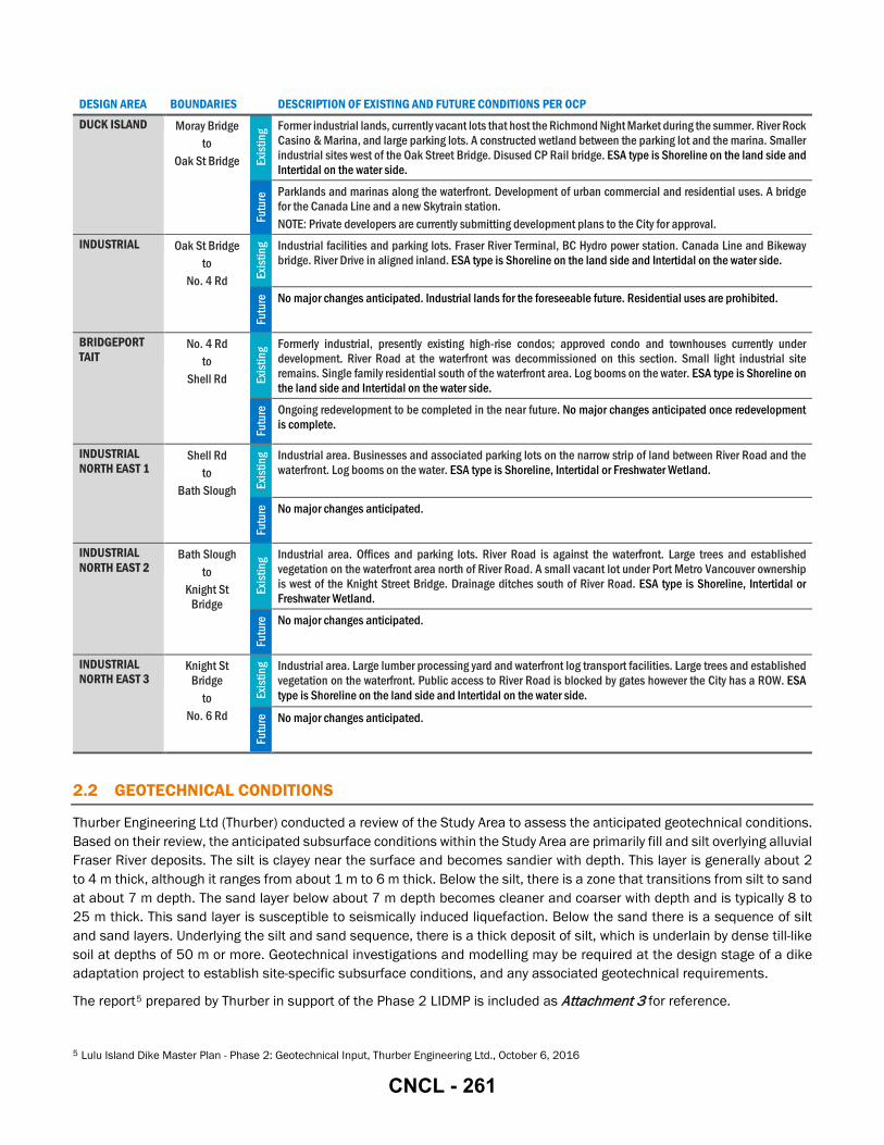
DESIGN AREA BOUNDARIES DESCRIPTION OF EXISTING AND FUTURE CONDITIONS PER OCP DUCK ISLAND Moray Bridge
to Oak St Bridge Ex
istin
g Former industrial lands, currently vacant lots that host the Richmond Night Market during the summer. River Rock Casino & Marina, and large parking lots. A constructed wetland between the parking lot and the marina. Smaller industrial sites west of the Oak Street Bridge. Disused CP Rail bridge. ESA type is Shoreline on the land side and Intertidal on the water side.
Futu
re Parklands and marinas along the waterfront. Development of urban commercial and residential uses. A bridge
for the Canada Line and a new Skytrain station. NOTE: Private developers are currently submitting development plans to the City for approval.
INDUSTRIAL Oak St Bridge to
No. 4 Rd Exist
ing Industrial facilities and parking lots. Fraser River Terminal, BC Hydro power station. Canada Line and Bikeway
bridge. River Drive in aligned inland. ESA type is Shoreline on the land side and Intertidal on the water side. Fu
ture
No major changes anticipated. Industrial lands for the foreseeable future. Residential uses are prohibited.
BRIDGEPORT TAIT
No. 4 Rd to
Shell Rd Exist
ing Formerly industrial, presently existing high-rise condos; approved condo and townhouses currently under
development. River Road at the waterfront was decommissioned on this section. Small light industrial site remains. Single family residential south of the waterfront area. Log booms on the water. ESA type is Shoreline on the land side and Intertidal on the water side.
Futu
re Ongoing redevelopment to be completed in the near future. No major changes anticipated once redevelopment
is complete.
INDUSTRIAL NORTH EAST 1
Shell Rd to
Bath Slough Exist
ing Industrial area. Businesses and associated parking lots on the narrow strip of land between River Road and the
waterfront. Log booms on the water. ESA type is Shoreline, Intertidal or Freshwater Wetland.
Futu
re No major changes anticipated.
INDUSTRIAL NORTH EAST 2
Bath Slough to
Knight St Bridge
Exist
ing Industrial area. Offices and parking lots. River Road is against the waterfront. Large trees and established
vegetation on the waterfront area north of River Road. A small vacant lot under Port Metro Vancouver ownership is west of the Knight Street Bridge. Drainage ditches south of River Road. ESA type is Shoreline, Intertidal or Freshwater Wetland.
Futu
re No major changes anticipated.
INDUSTRIAL NORTH EAST 3
Knight St Bridge
to No. 6 Rd
Exist
ing Industrial area. Large lumber processing yard and waterfront log transport facilities. Large trees and established
vegetation on the waterfront. Public access to River Road is blocked by gates however the City has a ROW. ESA type is Shoreline on the land side and Intertidal on the water side.
Futu
re No major changes anticipated.
2.2 GEOTECHNICAL CONDITIONS
Thurber Engineering Ltd (Thurber) conducted a review of the Study Area to assess the anticipated geotechnical conditions. Based on their review, the anticipated subsurface conditions within the Study Area are primarily fill and silt overlying alluvial Fraser River deposits. The silt is clayey near the surface and becomes sandier with depth. This layer is generally about 2 to 4 m thick, although it ranges from about 1 m to 6 m thick. Below the silt, there is a zone that transitions from silt to sand at about 7 m depth. The sand layer below about 7 m depth becomes cleaner and coarser with depth and is typically 8 to 25 m thick. This sand layer is susceptible to seismically induced liquefaction. Below the sand there is a sequence of silt and sand layers. Underlying the silt and sand sequence, there is a thick deposit of silt, which is underlain by dense till-like soil at depths of 50 m or more. Geotechnical investigations and modelling may be required at the design stage of a dike adaptation project to establish site-specific subsurface conditions, and any associated geotechnical requirements.
The report5 prepared by Thurber in support of the Phase 2 LIDMP is included as Attachment 3 for reference.
5 Lulu Island Dike Master Plan - Phase 2: Geotechnical Input, Thurber Engineering Ltd., October 6, 2016
CNCL - 261

2.3 ENVIRONMENTAL CONDITIONS
Richmond is located at the mouth of the Fraser River, an urban and agricultural City juxtaposed within the high ecological values of the Fraser River Estuary. The City’s Ecological Network Management Strategy (ENMS) provides context for the protection, enhancement and connectivity of an interconnected system of natural areas that make up Richmond’s distinctive landscape. The ENMS recognizes the essential ecosystem services integral to the subtidal, intertidal and upland riparian areas within the Study Area, such as water storage and filtration, wave energy attenuation, temperature mitigation and prevention of soil erosion. Green infrastructure, which refers to components of the natural and built environment that provide ecosystem services, are also promoted within the ENMS. A map of Riparian Management Areas (RMA’s) of Lulu Island is shown below in Figure 3 and provided in full size in Appendix B.
Figure 3: Riparian Management Areas (RMA’s)
Ecological lands within the LIDMP Study Area include City parks, RMA’s and ESA’s designated in the OCP, as well as other ecologically valuable lands such as the provincially designated Sturgeon Bank WMA. The LIDMP Study Area includes six of the ten geographic strategy areas identified within the ENMS: Traditional Neighbourhoods, City Centre, West Dike, WMA’s, Industrial Area and the Fraser River. The ENMS and associated Strategy Areas inform the LIDMP.
The ENMS encompasses all ecological lands in the City, regardless of tenure. Priorities to reduce the fragmentation of natural habitats is central to the ENMS principles. The LIDMP Study Area includes some of the City’s highest ecological values within the Fraser River delta. An overview of the City and non-City designated ecological attributes within the Study
CNCL - 262
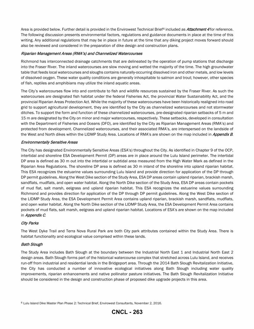
Area is provided below. Further detail is provided in the Envirowest Technical Brief6 included as Attachment 4 for reference. The following discussion presents environmental factors, regulations and guidance documents in place at the time of this writing. Any additional regulations that may be in place in future at the time that any diking project moves forward should also be reviewed and considered in the preparation of dike design and construction plans.
Riparian Management Areas (RMA’s) and Channelized Watercourses
Richmond has interconnected drainage catchments that are delineated by the operation of pump stations that discharge into the Fraser River. The inland watercourses are slow moving and wetted the majority of the time. The high groundwater table that feeds local watercourses and sloughs contains naturally-occurring dissolved iron and other metals, and low levels of dissolved oxygen. These water quality conditions are generally inhospitable to salmon and trout; however, other species of fish, reptiles and amphibians may utilize the inland aquatic areas.
The City’s watercourses flow into and contribute to fish and wildlife resources sustained by the Fraser River. As such the watercourses are designated fish habitat under the federal Fisheries Act, the provincial Water Sustainability Act, and the provincial Riparian Areas Protection Act. While the majority of these watercourses have been historically realigned into road grid to support agricultural development, they are identified by the City as channelized watercourses and not stormwater ditches. To support the form and function of these channelized watercourses, pre-designated riparian setbacks of 5 m and 15 m are designated by the City on minor and major watercourses, respectively. These setbacks, developed in consultation with the Department of Fisheries and Oceans (DFO), are identified by the City as Riparian Management Areas (RMA’s) and protected from development. Channelized watercourses, and their associated RMA’s, are interspersed on the landside of the West and North dikes within the LIDMP Study Area. Locations of RMA’s are shown on the map included in Appendix B.
Environmentally Sensitive Areas
The City has designated Environmentally Sensitive Areas (ESA’s) throughout the City. As identified in Chapter 9 of the OCP, intertidal and shoreline ESA Development Permit (DP) areas are in place around the Lulu Island perimeter. The intertidal DP area is defined as 30 m out into the intertidal or subtidal area measured from the High Water Mark as defined in the Riparian Area Regulations. The shoreline DP area is defined as 30 m inland of the shoreline into upland riparian habitat. This ESA recognizes the estuarine values surrounding Lulu Island and provide direction for application of the DP through DP permit guidelines. Along the West Dike section of the Study Area, ESA DP areas contain upland riparian, brackish marsh, sandflats, mudflats, and open water habitat. Along the North Dike section of the Study Area, ESA DP areas contain pockets of mud flat, salt marsh, eelgrass and upland riparian habitat. This ESA recognizes the estuarine values surrounding Richmond and provides direction for application of the DP through DP permit guidelines. Along the West Dike section of the LIDMP Study Area, the ESA Development Permit Area contains upland riparian, brackish marsh, sandflats, mudflats, and open water habitat. Along the North Dike section of the LIDMP Study Area, the ESA Development Permit Area contains pockets of mud flats, salt marsh, eelgrass and upland riparian habitat. Locations of ESA’s are shown on the map included in Appendix C.
City Parks
The West Dyke Trail and Terra Nova Rural Park are both City park attributes contained within the Study Area. There is habitat functionality and ecological value comprised within these lands.
Bath Slough
The Study Area includes Bath Slough at the boundary between the Industrial North East 1 and Industrial North East 2 design areas. Bath Slough forms part of the historical watercourse complex that stretched across Lulu Island, and receives run-off from industrial and residential lands in the Bridgeport area. Through the 2014 Bath Slough Revitalization Initiative, the City has conducted a number of innovative ecological initiatives along Bath Slough including water quality improvements, riparian enhancements and native pollinator pasture initiatives. The Bath Slough Revitalization Initiative should be considered in the design and construction phase of proposed dike upgrade projects in this area.
6 Lulu Island Dike Master Plan Phase 2: Technical Brief, Envirowest Consultants, November 2, 2016.
CNCL - 263
Ecological Network Management Strategy (ENMS) Strategy Areas
Both inland and foreshore ecological values are embedded within the six ENMS Strategy Areas. The ENMS and associated Strategy Areas provide key ecological context within the Study Area. ENMS Strategy Areas as shown on the map included in Appendix D.
Wildlife Management Area (WMA) – Sturgeon Bank
Sturgeon Bank is a provincially designated Wildlife Management Area (WMA) established in 1998 and is located on the water side of the West Dike. It is protected for the conservation of critical, internationally-significant habitat for year-round bird migration and wintering waterfowl populations. It is also important fish habitat. It is comprised primarily of near shore and intertidal brackish marsh, sandflats, mudflats, and open water. The WMA foreshore marsh and mudflat habitats provide critical ecological values as well as ecosystem services for wave energy attenuation and shoreline erosion and stabilization. Consideration for these key climate change adaptation and resiliency attributes along Sturgeon Bank should be considered in the design and construction phase of proposed dike upgrade projects in this area.
Fraser River Estuary Management Program (FREMP) Mapping
Since the mid-1980’s habitat productivity mapping has been undertaken along the Fraser River shoreline from the mouth of the Fraser River Delta upstream to the Pitt River/Maple Ridge area. This mapping was undertaken by the former Fraser River Estuary Management Program (FREMP). FREMP was a cooperative agreement amongst member agencies, including Environment Canada, Fisheries and Oceans Canada, Transport Canada, Fraser River Port Authority, North Fraser Port Authority, BC Ministry of Environment, and the Greater Vancouver Regional District. Though FREMP ceased to exist in 2013, the City continues to utilize this data resource to inform activities in and along the City’s Fraser River foreshore. The FREMP classification system comprises a three tiered colour-coded system: habitats are colour-coded red, yellow or green. Red-coded shorelines sustain highly productive fish and wildlife habitats. Yellow-coded shorelines sustained moderately productive habitats, while green-coded shorelines were characterized by habitats of low productivity. Generally development constraints are greatest within red-coded habitats, while development within green-coded habitats are constrained the least. Habitat productivity within the LIDMP Study Area includes a majority of red-coded reaches along the West Dike and North Arm.
Detailed maps showing habitat coding throughout the Study Area are presented in Appendix E. An overview of the foreshore habitat coding in the Study Area is shown in Figure 4. High productivity habitat is depicted to extend along the north dike generally from No. 6 Road to the Knight Street bridge, along the Tait Waterfront Park, from No.4 Road to the Canada Line bridge, under the Oak Street Bridge, immediately west of the River Rock casino, south of the Canada Line YVR line, and west of Hollybridge Way to the Terra Nova Rural Park. Moderate and low productive habitat are interspersed along this shoreline between Hollybridge Way and Knight Street bridge. High productivity habitat is depicted to extend along the entire sea-ward edge of the west dike fronting Sturgeon Bank and Terra Nova Rural Park.
Fraser River Fish and Species at Risk Values
The Fraser River Estuary contains rich habitat for many species of fish and wildlife. Estuary marshes support a significant portion of the regions migrating salmon. While the inland watercourses are generally considered to not be hospitable to salmon and trout species, they do flow into and support fish life in the Fraser River and are therefore considered to be nutrient providing fish habitat.
A desktop review for species of management concern (i.e. included in Schedule 1 of the Federal Species at Risk Act, and Provincial Conservation Data Centre red- and blue-listed species) was undertaken on the Provincial Conservation Data Centre web map. The search provided a single result, specifically utilization of the Fraser River by white sturgeon. The search did not provide any results along the seaward extent of the west dike, or along inland channelized watercourses . The absence of search results does not indicate that species at risk or of management concern are absent, but that they have either not been observed and /or recorded within these areas. A detailed species at risk assessment will need to be undertaken at the time of design construction as the potential for listed species such as white sturgeon, Vancouver Island beggertick, streambank lupin etc. within the Study Area is high.
CNCL - 264
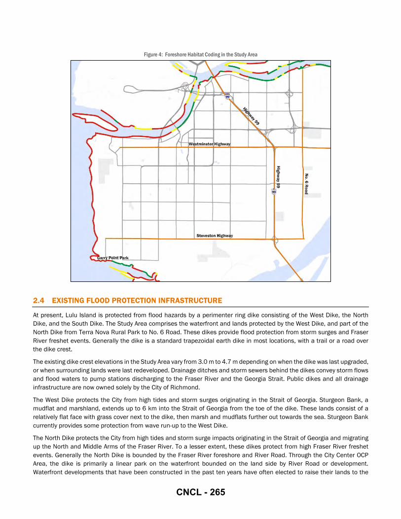
Figure 4: Foreshore Habitat Coding in the Study Area
2.4 EXISTING FLOOD PROTECTION INFRASTRUCTURE
At present, Lulu Island is protected from flood hazards by a perimenter ring dike consisting of the West Dike, the North Dike, and the South Dike. The Study Area comprises the waterfront and lands protected by the West Dike, and part of the North Dike from Terra Nova Rural Park to No. 6 Road. These dikes provide flood protection from storm surges and Fraser River freshet events. Generally the dike is a standard trapezoidal earth dike in most locations, with a trail or a road over the dike crest.
The existing dike crest elevations in the Study Area vary from 3.0 m to 4.7 m depending on when the dike was last upgraded, or when surrounding lands were last redeveloped. Drainage ditches and storm sewers behind the dikes convey storm flows and flood waters to pump stations discharging to the Fraser River and the Georgia Strait. Public dikes and all drainage infrastructure are now owned solely by the City of Richmond.
The West Dike protects the City from high tides and storm surges originating in the Strait of Georgia. Sturgeon Bank, a mudflat and marshland, extends up to 6 km into the Strait of Georgia from the toe of the dike. These lands consist of a relatively flat face with grass cover next to the dike, then marsh and mudflats further out towards the sea. Sturgeon Bank currently provides some protection from wave run-up to the West Dike.
The North Dike protects the City from high tides and storm surge impacts originating in the Strait of Georgia and migrating up the North and Middle Arms of the Fraser River. To a lesser extent, these dikes protect from high Fraser River freshet events. Generally the North Dike is bounded by the Fraser River foreshore and River Road. Through the City Center OCP Area, the dike is primarily a linear park on the waterfront bounded on the land side by River Road or development. Waterfront developments that have been constructed in the past ten years have often elected to raise their lands to the
CNCL - 265

dike crest elevation, forming a superdike. A superdike is formed whenever the lands behind the dike are filled to the same elevation as the dike crest, and development is built on a ground elevation equal to the dike crest. Superdikes are discussed in greater detail in Section 4.1.2. Through the industrial areas north of the City Center, the dike remains generally earthfill with sections of sheet pile and floodwalls associated with specific sites.
2.5 EXISTING FLOOD PROTECTION POLICY
The City of Richmond has two primary policies in place that guide flood protection initiatives. The OCP establishes flood protection as a priority in the context of land use planning. Flood proofing objectives are enforced through Bylaw No. 8204.
At present, the OCP states that ESA’s serve the dual purpose of planning for environmental and flood protection needs. Flood protection has been established as a priority alongside environmental priorities within the OCP, especially in areas that are designated ESA’s. This includes the entire waterfront of the Study Area. The OCP also establishes a priority for a green infrastructure network throughout the City’s ecological network, including the intertidal, shoreline and upland riparian areas. A green infrastructure network integrates the built and natural environment to realize associated ecosystem services such as flood mitigation, and stormwater management.
The City currently enforces flood proofing through the Flood Plain Designation and Protection Bylaw No. 8204, established in 2008 to set minimum Flood Construction Levels (FCL’s) throughout the City. The FCL prescribes the minimum elevation where the underside of a floor system can be constructed. The By-law also provides for diking needs such as ROWs by specifying that lands at a certain distance from the dike or waterfront must be dedicated to dike works.
Proposed developments at the waterfront must commit to implementing flood protection measures in order to secure approval for development plans. These are typically negotiated with the City on a site-by-site basis. In recent years, residential developers have voluntarily raised the elevation of development lands to the same elevation as the dike crest (creating a superdike) to ensure that the units on the ground floor will have a view of the water.
3 Considerations The considerations in this section were used to evaluate potential flood protection adaptations to make the recommendations that comprise the Phase 2 LIDMP. Any flood protection adaptation, whether in compliance with or deviating from the Phase 2 LIDMP, should use the following considerations in evaluating the suitability of a proposed flood protection project for implementation. It is important that any proposed project avoid or mitigate negative impacts, while maximizing the benefits, as a balance of the following considerations. In the event that a dike adaptation project differs from the recommended adaptation for that design area, the project should still take these considerations into account. These considerations outline important factors that should be incorporated into the implementation plans for both structural adaptations that will alter the existing landscape, or policy adaptations that have indirect impacts on the landscape.
3.1 FLOOD PROTECTION CONSIDERATIONS
The City has established a design crest elevation of 4.7 m with consideration to be further raised to 5.5 m in response to climate change and sea level rise predictions. These design crest elevations have been adopted by the City in response to a combination of sea level rise predictions (1.0 m) and land subsidence (0.2 m)7, anticipated to materialize by the year 2100.
Increases in dike crest levels (up to 4.7 or future 5.5 m) to address sea level rise and climate change are anticipated to be staged and implemented over the next few decades to respond to rising sea levels. The City will continue to monitor sea level rise and adjust the target dike crest elevations as required. Any flood protection project in the Study Area should, at
7 Sea Level Rise Adaptation Primer, Arlington Group et. al, January 2013
CNCL - 266

a minimum, adhere to these elevations. Additional regional guidelines should also be considered at the design stage of dike improvements.
Adaptations should be compatible with existing dikes and other flood protection measures adjoining the site of proposed works. Connections to existing flood protection works should be designed to ensure there will not be inconsistencies or weak points where an adaptation meets a pre-existing dike.
3.2 ENVIRONMENTAL CONSIDERATIONS
The Study Area is situation along the Georgia Strait and the Fraser River, two important fish and wildlife habitats. There are also riparian areas and intertidal zones that have ecological value. Any diking projects should be well-integrated with the surrounding natural realm, and should be designed to mitigate alterations that compromise the local environment, either aesthetically or ecologically. The Study Area includes substantial open space and parklands, including wetlands and natural areas on the waterfront. The City has an interest in preserving the environment at the waterfront for public uses, in particular the dike trail for cyclists and pedestrians. The aesthetic value of the natural environment along the trails should be considered as well as ecological significance.
The breadth of ecological values comprised within the study area is reflective of estuary habitats as described in Section 2.3. The perimeter ring dike in the Study Area is flanked by either ripariam or upland ESA habitat to the landside, and high value shoreline & intertidal ESA or WMA habitats on the foreshore. Any proposed dike design and construction projects should undertake an assessment of the adjacent ecological values to determine the most appropriate dike design and footprint using an approach to avoid alterations in high value habitats, and if that is not feasible, then mitigate or compensate with a net gain approach. The Study Area is comprised of large tracts of open space and park lands that contribute significant aesthetic values within the estuary which must be considered in concert with the ecological values.
An overview of the federal and provincial regulatory context is provided above in Section 2.3. Detrimental impacts to the environment are to be avoided wherever possible, in accordance with the City’s environmental regulations. In addition, sea level rise should be monitored and reviewed in order to determine the impact on existing foreshore wetlands within the Study Area. Additional guidance documents outlining the City’s environmental protection and enhancement strategies are listed in Section 1.3. Any flood protection project should be prepared by qualified persons having reviewed and understood these documents, as well as any environmental guidance documents or regulations in effect at the time a project is proposed. The design of proposed diking projects should follow the City’s approach regarding the priority to avoid habitat impact first. Where that is not feasible, enhancement and mitigation may be pursued with a net gain approach.
3.3 GEOTECHNICAL CONSIDERATIONS
Geotechnical design considerations for dike adaptations include seepage control both under and through the dike, dike slope stability, dike crest settlement, and seismic performance. Furthermore, additional loading from increased dike size over any existing structures, such as building footings or bridge abutments, will need to be verified for confirmation that existing infrastructure will not be negatively impacted. Other types of structural flood protection measures will also need to be verified for impacts to existing infrastructure.
Thurber has reviewed the existing geotechnical conditions in the Study Area. Their comments on the key design considerations are outlined on the following pages.
Seepage
Seepage risk should be assessed and mitigated for any dike adaptation project, whether for dikes or floodwall systems. Seepage becomes problematic where water flow through or under the dike dislocate the fill materials forming the dike, which may weaken the integrity of the dike and increase the risk of failure during high water events. Adaptations should be designed with proper drainage to mitigate seepage risks.
Increasing the height of an existing dike to 4.7 m or 5.5 m may increase the design flood height, defined as the height from the ground at the land side toe of the dike to the height of water against the dike during a high water event. Existing dikes
CNCL - 267

are between 3.0 m and 4.7 m, and the ground elevation on the landside of the dikes is generally at about 2.0 m. Raising an existing dike may also increase the flood height, unless the lands adjacent to the dike are also raised in conjunction with crest height increases, forming a superdike. Increasing the flood height may increase risks of landside heave of the less permeable surficial silt layer, and piping through the dike or its foundation.
Piping occurs when excessive seepage forces cause the migration of soil particles through the soil matrix resulting in internal erosion and eventually retrogressive failure. Heave can occur when there are excessive hydraulic pressures on the landside of the dike caused by a lower permeability soil layer forming a cap over a more permeable layer near the ground surface. Heave can lift and fracture the cap, causing large localised seepage volumes and internal erosion, which could cause a dike breach.
To provide reliable protection from higher design flood heights, a system of seepage control measures will likely be required for any dike adaptation project. The potential for heave and piping may be mitigated using relief wells, drainage blankets or trenches to drain water from behind the dike face to an outlet such as a sewer or ditch. The receiving system’s capacity should be verified to ensure drainage can be accommodated in the system. Relief wells and trenches should be designed with filters, such as a geotextile, to prevent piping and internal erosion. Seepage exits should be similarly protected with filters to minimize risk of fill materials migrating out of the dike.
Where there are ditches at the toe of an existing dike, filling the ditches may be considered within the scope of a proposed dike adaptation project. Ditches at the toe of a dike increase the risk of piping, since these ditches shorten the seepage path length and increase the hydraulic gradient. Filling the ditches may contribute to a comprehensive plan to reduce the risk of seepage.
Seepage potential should be evaluated and mitigated for any structural adaptation, as seepage may cause build-up of pressures behind the structure that may increases risks of failure. Constrained dikes, designed with a retaining wall on one or both sides, may be less susceptible to seepage risk if the dike face is a uniform material, such as a concrete cut-off wall or a floodwall. A dike face constructed with a segmental wall system, such as lock blocks or armour stone, may need to have the joints between segments grouted to prevent seepage at the joints.
Stability
Any dike adaptation project should be designed and constructed to withstand pressures and forces it may be subjected to during a high water event. For dike adaptations, high quality dike fill materials should be used and placed in accordance with accepted engineering practice to maximize stability. The standard dike section is anticipated to be generally stable with increased flood heights, although it will be less stable than the lower height configuration. In areas where stability is a concern, minor modifications to the standard dike section may be required, such as flattening the landside slope, constructing a toe berm or providing a seepage cut-off and filter within the dike. The stability of dikes may be further improved where ditches at the landside toe are infilled.
Settlement
Any dike adaptation project should be designed and constructed with consideration for settlement. Designs that minimize settlement are preferred, though some measure of settlement is anticipated in the long-term in all cases.
Raising existing dikes may induce consolidation settlement of the surficial silt layers. This settlement could be up to about 5% of the increase of the thickness of new dike fill placed. Dikes and surrounding areas may also experience compression settlement due to on-going long-term compression of deeper silt layers. This ongoing settlement is typically in the range of 1 to 2 mm per year for dikes built on soil conditions in Richmond. Settlement could potentially be compensated for by overbuilding the dike to a higher initial crest elevation, anticipating that it will settle to the target dike crest.
Local soil properties should be investigated prior to finalizing the design of any adaptations. Where construction is over peat or highly organic soils, settlement may be higher.
CNCL - 268

Seismic Performance
The Provincial Seismic Design Guidelines for Dikes8 (Seismic Guidelines) published in June 2014 recommends designing high consequence dikes to control seismic deformations within prescribed limits. For a trapezoidal dike to achieve the objectives of the Seismic Guidelines, ground improvement may be required. Ground improvement reduces seismic vulnerability by densifying the foundation of the dike. Compaction of the ground underlying the dike may achieve the targets in the Seismic Guidelines. However, more intensive methods such as deep soil mixing or vibro-replacement to a specified depth may be pursued if compaction alone is found to be insufficient. These ground improvements may be very costly. Dikes that are set back from the waterfront are more resistant to seismic events due to being restrained by earth at both dike toes, as compared to a waterfront dike where the waterside toe is much deeper and may provide less force anchoring the dike in place. Therefore, setback dikes require less intensive methods to meet the Seismic Guidelines. Likewise, widening the dike crest to create a superdike increases resilience to seismic events without typically requiring ground improvements. Superdikes are discussed in greater detail in Section 4.1.2.
To further understand the potential seismic risks to dikes within the Study Area, Thurber conducted seismic deformation analyses at three select locations (No. 1 Road Pump Station, No. 4 Road Pump Station, and Bath Slough Pump Station). Results are included in their Seismic Deformation Analysis report9 included in Attachment 5. Results from the assessment identified that at the three sites selected, horizontal deformations were within the allowances prescribed for the 1:2,475 year event by the Seismic Guidelines. Vertical deformations exceeded the tolerances; however, overbuilding the dike to provide post-earthquakle freeboard may be an acceptable alternate to meet the Seismic Guidelines instead of costly ground improvements. The results are largely depended on the underlying soil conditions, slope of the riverbank, and depth of the river bottom. Larger deformations could be expected where the river channel is deeper and steeper. The results discussed in the Seismic Deformation Analysis pertain only to the three sections analyzed; these are generally representative of Lulu Island however the results cannot be assumed to be consistent for any other locations. At the design stage of a proposed dike adaptation project, a site-specific seismic deformation analysis should be conducted to confirm seismic risks, and possible mitigation requirements. A seismic deformation analysis, for example a Plaxis model, may inform whether ground improvements may be required, and what level of ground improvements may be required to meet the Seismic Guidelines.
3.4 INFRASTRUCTURE CONSIDERATIONS
It is advantageous to pursue dike works alongside other infrastructure upgrades in the vicinity of the dike. Where infrastructure works are proposed on the waterfront, local diking needs should be evaluated and included in the scope of proposed work wherever possible. For example, when a road is being raised or resurfaced, the adjacent dike could be upgraded concurrently. Including dike adaptations within the scope of other municipal works may also present a cost savings as compared to pursuing projects independently. The resulting dikes may also be better integrated with the local landscape if they proceed concurrently with neighbouring infrastructure upgrades.
Any impacts to local stormwater drainage patterns should be evaluated to ensure compatibility with the local infrastructure, such as pump stations or roads. Where adaptations will interfere with existing drainage patterns, the capacity of the receiving pump station must be confirmed. If ditches at the toe of the dike are to be filled, the associated loss of stormwater storage and conveyance functions may need to be compensated with underground pipes or alternative systems.
Above ground utilities may be impacted by diking projects. Utility poles may need to be temporarily relocated while dike works are underway, and relocated to a permanent position when works are complete. There may be an opportunity to relocate cables underground when dike works proceed, particularly if roadworks are included. The dike trail and associate park infrastructure, such as park benches and lookouts, may need to be relocated to accommodate dike adaptations.
8 Seismic Design Guidelines for Dikes, 2nd ed., Golder, Ministry of Forests Lands and Natural Resources (MFLNRO) Flood Safety Section, Jun 2014 9 Lulu Island Dike Master Plan - Phase 2: Seismic Deformation Analysis, Thurber Engineering Ltd., Sep 12, 2016
CNCL - 269

3.5 SITES WITH UNIQUE CONSTRAINTS
There may be sites with unique features that must be accommodated when adaptations proceed. Dike adaptations may be realigned to avoid special sites, however this may not always be feasible. Where development and infrastructure exists along the waterfront where a dike adaptation project would ideally proceed, a custom design to accommodate that site may be required. Examples include pump stations, bridges, or industrial sites located immediately on the water. There are a number of bridges in the Study Area. Adaptations at bridge sites are discussed further under Section 4.3.
The adjoining adaptations on either side of the special site should be well-integrated with that site’s custom adaptation design, to ensure there are no vulnerabilities in the flood protection strategy at the boundaries between adaptation types. For example, a section of floodwall within a dike should be protected at the joints to ensure the joints are as robust as both the dike and floodwall. The joints should be as capable of withstandard high water levels as the adaptations on either side.
3.6 SOCIAL CONSIDERATIONS
Dike adaptations should be designed with consideration of the public realm. The City’s 2009 Waterfront Strategy presents a vision that promotes community wellness, economic vitality and a healthy environment through initiatives that integrate the waterfront with the urban landscape. The Study Area contains recreation, culture and heritage resources to be preserved wherever feasible, according to the regulatory protections in place for heritage resources. Recreational uses may include walking and cycling on the trail, as well as offshore activities such as sport fishing and boating.
Heritage sites may be treated as sites with unique constraints, as described in Section 3.5, that require special accommodations within a diking project. Heritage sites that have been identified as culturally significant should be preserved per the Heritage Procedures Bylaw 8400 as applicable.
Any impacts that restrict use and enjoyment of the waterfront, as well as views of the waterfront, should be mitigated. Impacts on cultural and heritage resources limiting the accessibility of these sites should be mitigated. Sites should remain accessible to all people including those using mobility aids, such as wheelchairs or crutches.
Public access to the waterfront is provided by the perimeter dike trail system. Where waterfront access is constrained, the City’s Parks Planning and Design (Parks) department has identified connectivity at the waterfront as preferable to inland trail detours. For example, where the existing dike trail alignment crosses under low bridges, raising the dike may not provide adequate clearance to maintain the trail over the dike. The preference is to keep the trail at the waterfront. A boardwalk at the waterside toe of the dike would be a preferred approach as opposed to directing pedestrians up to the road to circumvent a barrier.
Adaptations should be aesthetically integrated with the surrounding area. For example, in recreational areas or ecological landscapes, adaptations that do not detract from the natural beauty of the local environment are preferable to those adaptations requiring severe hardscaping, such as concrete or retaining walls. The local character of industrial areas is amenable to man-made structures thus floodwalls may be in keeping with the landscape themes in industrial areas.
Adaptations should support, and be integrated with, the habitat functionality and aesthetics of the surrounding environment.
3.7 PROPERTY CONSIDERATIONS
The City must have permanent access to the dike adaptations in the long-term, for both construction and ongoing maintenance operations. Acquiring property may add considerable costs to a diking project. Wherever feasible, adaptations should proceed within the lands that are already under City ownership, or that the City may access through easements or right-of-ways (ROW’s).
Much of the City’s waterfront was developed prior to the establishment of robust policies for dedicating lands to diking. As a result, older buildings remain directly on the waterfront, or within 30 m from the natural boundary. In cases where no alternative alignment can be implemented, it may be necessary for the City to acquire waterfront lands or obtain easements or ROWs to construct or maintain adaptations.
CNCL - 270
3.8 ECONOMIC CONSIDERATIONS
For the purposes of the Phase 2 LIDMP, economic considerations encompass impacts to local businesses operating in the vicinity of existing or proposed dikes. The cost of adaptation projects is also an economic consideration, however for the purposes of the Phase 2 LIDMP these will be referred to as “cost considerations,” discussed further under Section 3.10.
Flood protection projects provide an overall economic good by preventing damage to assets. However, any changes to existing conditions may trigger negative impacts to the local economy. For example, diking may damage views to the waterfront, or challenge industrial activities by limiting water access.
Where economic impacts cannot be completely avoided, they should be mitigated to the extent feasible. Dike adaptations should consider local economic factors in the overall decision making context.
Lands that were formerly used for economic purposes, such as waterfront shipping facilities, but are no longer being used for economic activities may be suitable lands for dike adaptations. If alternative lands are available that do not have any associated economic uses, those lands should be used rather than compromising lands of economic interest.
3.9 OPERATIONAL CONSIDERATIONS
Dikes in the Study Area provide access to City assets that must be maintained, such as drainage ditches and trails. Adequate clearance must be retained for maintenance vehicles to navigate the dikes where required, and carry out maintenance activities. For example, if a dike is raised in an area where there are drainage ditches at the dike toe, the boom of an excavator on the dike must be able to reach the ditches for cleaning and maintenance.
Raising a dike may complicate access as the slopes must remain suitable for maintenance and emergency access. Additional lands may be required to improve access to the dike.
3.10 COST CONSIDERATIONS
The overall cost of implementing adaptations is driven by a number of factors that include habitat consideration, land acquisition and ground improvements. When evaluating the cost of an adaptation, the costs of all associated works and mitigation plans should be included. A project with relatively higher construction costs may still be the least expensive option if it does not require any habitat compensation, for example.
3.11 STAKEHOLDER FEEDBACK
The diking solutions were presented to key stakholders and the general public. The public and key stakeholder groups were pleased with the City’s proactive approach to addressing climate change and sea level rise in the community. Comments with the West Dike and North Dike (from Terra Nova to No. 6 Road) related to the height in which the dikes would be raised, possible increased dredging needs, and the disruption it may cause to the environment, wildlife and their habitats were raised.
Two public open houses were held to present the flood protection concepts for the Phase 2 area. The first session was held at City Hall on April 20th, 2017 and the second session was held at the City Centre Community Centre on June 21st, 2017. All materials provided at the Open Houses were made available on the City’s community engagement website address, Letstalkrichmond.ca. There were 532 individuals that viewed the project on this website, 68 of which provided feedback.
A summary of the open house and website feedback is presented in Table 2.
CNCL - 271
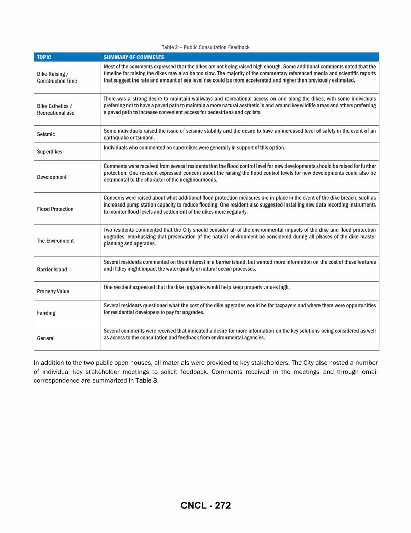
Table 2 – Public Consultation Feedback
TOPIC SUMMARY OF COMMENTS
Dike Raising / Construction Time
Most of the comments expressed that the dikes are not being raised high enough. Some additional comments noted that the timeline for raising the dikes may also be too slow. The majority of the commentary referenced media and scientific reports that suggest the rate and amount of sea level rise could be more accelerated and higher than previously estimated.
Dike Esthetics / Recreational use
There was a strong desire to maintain walkways and recreational access on and along the dikes, with some individuals preferring not to have a paved path to maintain a more natural aesthetic in and around key wildlife areas and others preferring a paved path to increase convenient access for pedestrians and cyclists.
Seismic Some individuals raised the issue of seismic stability and the desire to have an increased level of safety in the event of an earthquake or tsunami.
Superdikes Individuals who commented on superdikes were generally in support of this option.
Development
Comments were received from several residents that the flood control level for new developments should be raised for further protection. One resident expressed concern about the raising the flood control levels for new developments could also be detrimental to the character of the neighbourhoods.
Flood Protection
Concerns were raised about what additional flood protection measures are in place in the event of the dike breach, such as increased pump station capacity to reduce flooding. One resident also suggested installing new data recording instruments to monitor flood levels and settlement of the dikes more regularly.
The Environment
Two residents commented that the City should consider all of the environmental impacts of the dike and flood protection upgrades, emphasizing that preservation of the natural environment be considered during all phases of the dike master planning and upgrades.
Barrier Island Several residents commented on their interest in a barrier island, but wanted more information on the cost of these features and if they might impact the water quality or natural ocean processes.
Property Value One resident expressed that the dike upgrades would help keep property values high.
Funding Several residents questioned what the cost of the dike upgrades would be for taxpayers and where there were opportunities for residential developers to pay for upgrades.
General Several comments were received that indicated a desire for more information on the key solutions being considered as well as access to the consultation and feedback from environmental agencies.
In addition to the two public open houses, all materials were provided to key stakeholders. The City also hosted a number of individual key stakeholder meetings to solicit feedback. Comments received in the meetings and through email correspondence are summarized in Table 3.
CNCL - 272

Table 3 – Other Key Stakeholder Feedback
STAKEHOLDER SUMMARY OF COMMENTS
Provincial Inspector of Dikes
The Deputy Inspector of Dikes did not foresee any major issues in moving forward with the master plan, but noted that additional discussion and correspondence would be required where alternative strategies that deviate from the existing flood protection (e.g. superdikes) are proposed.
City of Richmond Advisory Committee for the Environment
The Advisory Committee for the Environment (ACE) did not have any comments after the City presented the Phase 2 LIDMP to them in April 2017.
Urban Development Institute
The Urban Development Institute (UDI) noted that the Phase 2 LIDMP will mutually benefit the City of Richmond and UDI as the flood protection solutions will increase the livability and value of development within the City. UDI has acknowledged support of the presented flood protection strategies with the awareness that there could be increased costs incurred by the development industry.
Port of Metro Vancouver
Port Metro Vancouver (PMV) had the following comments: • The Vancouver Fraser Port Authority (VFPA) does not have any infrastructure in the area and the report recommendations
do not affect the two Port Sites within the study areas. • The report refers to secondary dikes that work in conjuction with primary dikes. Has consideration been given to
extending the secondary sike concept to inlands (perhaps through improving performance/raising elevations of existing roads) to provide redundancy and limit extent of area being flooded in the event a section of dyke is breached?
City of Richmond Heritage Commission
The Heritage Commission supports the “Dike Master Plan – Phase 2” initiative and recommends that staff/Council take into account the cultural and historical aspect of the diking system as imporvements are designed and implemented.
Department of Fisheries and Oceans – Small Craft Harbours Branch (SCH)
The Small Craft Harbours (SCH) Branch of the Department of Fisheries and Oceans provided the following comments: • The longer the distance incoming storm waves travel over shallow tidal flats the less vulnerability and the need for dike
wave run-up freeboard and armouring. The concept is to provide replacement for lost sediment nourishment to and allow natural wave action to distribute the sediment pile gradually over the flats over time (as used to be the case prior to manmade deflection and interception of river supplied Sturgeon Bank sediment accretion). This would go hand in hand with investigating the details of the more intrusive and expensive approach of constructing offshore barrier islands as mentioned in the report.
• The offshore berms could be a challenging geotechnical and coastal design with considerable expense and risk. • A side observation is the likely contributing effects of dredging of the legacy Fisherman' slough harbour cut into the
southern area of the flats. This probably confounds the above situation in that it provides a sediment "sink" for any mobile sediments that fined their way into the harbour "hole" which is then removed from time to time by dredging and removed from the system by disposal at sea. Either the slough harbour should be isolated in such a way so as not to be a sediment sink or it should be eliminated. In any situation, material removed from the slough belongs on the tidal flats and not removed and dumped in deep water.
• Considering the above, there are a couple of primary observations that map directly to the Phase 2 report. Firstly, making it clear that the erosional loss of elevation and width of the tidal flats of Sturgeon Bank due to a century of indiscriminate messing about with the natural sediment regimes needs to be highlighted. It is inferred in the report but does not stand out. This is the core of the seaward vulnerabilities both present and future with SLR. I am aware for instance that Golder has produced a DRAFT (2015) report on the erosion of Point Grey which has similar issues regarding loss of sediment supply and erosion of tidal flats and perhaps should be appended to the Sturgeon Bank Report.
• The proposals for the barrier islands are a conceptual means to address the problems of protecting the dikes from increased wave attack and a "squeeze" on the upper shore, including wave run up on dikes. This squeeze will be aggravated by SLR as the deeper water allows for both larger storm waves penetrating to the dike as well as increased erosion of the highly mobile tidal flat due to both the intensity of wave induced particle movements, increased transport by tide induced flows and the net amount of time of these conditions occurs. To aggravate the situation, storm waves will be partially reflecting from a rock armoured dike. Tidal flood and ebb and storm setup currents behind and around the barrier islands would be likely to cause gullying of the fine tidal flat sediments. Anything that puts sediment back to accrete and be wave sorted naturally and gently on the tidal flats and upper marsh zones, whether deflected from the river freshens or enhanced artificially with placement (i.e. dredgeate) should have net positive outcomes provided the material is "clean" biologically speaking, and is representative in the mix of sand and silt particle sizes of what had been deposited naturally in the past.
• We would have reservations about the more intrusive barrier island concept. It is complicated and it would lead to significant wave concentration at the hardened boundaries of the armoured islands. They would also create concentrated tidal flow and wave induced currents. The fine particle size silty sands of the outer flats would be extremely sensitive to those flows and also to compression and settlement under the weight and cyclical tidal buoyancy fluxes of
CNCL - 273
STAKEHOLDER SUMMARY OF COMMENTS the placed islands. Being well out into the deep water, exposed to higher wave regimes, the islands would need to be Rock armoured and constructed to very rigorous standards to stay put. Indeed they would have to be constructed very expensively as rock breakwaters. As such, they would also load the delta slopes and under earthquake shakes would likely increased the risk of major deltaic slumps or slides into deep water.
The SCH Branch provided the following conculsions: • A serious study of the history, evolution and current status of the flats including updated data on the hydrographic
changes, the sediment size characteristics today and yesterday, the baseline sediment chemical conditions (I.e. Pah's) and of course the biological values both current and historic with the trends indicated.
• A serious pilot program to place clean Fraser River silty sands into the tidal flats regime, probably as before, placed in one corner and allowed to spread by wave action over time. This would be monitored for effects and quality, and then linked to the potential for being part of a larger long term sediment management plan, encompassing Sturgeon Bank flats, and both Cannery Channel and the Ports shipping channel.
The SCH Branch provided the following additional comments on the report document: Executive Summary
• “For example, barrier islands that reduce wave run-up to eliminate the need for additional target crest increases,”… SCH Comment: And/or barrier islands in concert with restoring intertidal sediment supply and elevations as part of overall sediment management plan including redirection of dredgeate and in river sediment bypassing.
• FCL should be incorporated in planning for small craft harbours harbour buildings and infrastructure as well as potential increased use of floating structures for enhanced adaptation long term.
• SCH Comment: Restoring sediment input to intertidal areas may be an environmental net gain if done in an integrated manner.
Additional Guidance Documents • With respect to the Phase 2 LIDMP reference to the existing Floodplain Designation and Protection By-Law 8204, it
should be linked with overall Fraser River sediment management plan. Past practices and jurisdictional stovepipes have increased flood risk to West Dike area due to reductions of previous natural rates of sediment accretion and intertidal elevation.
• The 2015 Ecological Network Management Strategy items are a potential fit with in river sediment bypass as well as sediment nourishment to sturgeon bank tidal flats.
Environmental Conditions • What has been and will be the impacts to the environmental sensitive areas due to the combination of lowered intertidal
elevations combined with SLR and what might be done to reverse impacts over time? • High productivity habitat is depicted to extend along the entire sea-ward edge of the west dike fronting Sturgeon Bank
and Terra Nova Rural Park, but could be negatively impacted if tidal flat elevations do not keep pace with SLR armouring of west dikes would aggravate erosion of tidal flats.
• There is an overall lack of comprehensive data on the species risk within the study area. This should be a top priority.
Flood Risk Management Adaptations • Small craft harbours could continue science examination of nourishment to intertidal areas as part of overall sediment
management plan. • With respect to breakwaters and barrier islands, there is an opportunity for SCH to provide resources and guidance in
the planning process. • With respect to enhancement of intertidal habitat, the City could restore wide flat and elevated tidal flats uniformly with
or without barrier islands. • With respect to barrier islands, raised islands may be more problematic than simply restoring sediment nourishment to
raise overall tidal flats. • There is an overall lack of comprehensive data on the species risk within the study area. This should be a top priority. • With respect to slough dredging, any repeated dredging of the slough may be contributing to impacts on tidal flats
especially if mandated to be disposed out of the sturgeon bank sediment regime by ocean disposal regulations. • With respect to discussion of breakwaters, expand to encompass raising of tidal flats with restored sediment supply.
CNCL - 274

4 Flood Risk Management Adaptations Flood Risk Management adaptations have been categorized as either area wide or area specific.
Ultimately the City’s goal is to fortify the perimeter ring dike to a design crest elevation of 4.7 m, with consideration to be further raised to 5.5 m in response to climate change and sea level rise predictions. Area wide adaptations are those that facilitate the City’s flood protection objectives in tandem with the dikes or alternative protection measures in place at the waterfront. These could be policy adaptations, structural measures, or enhancement of green infrastructure to secure additional benefits to an adaptation that will achieve the 4.7 m crest elevation. Area wide adaptations may not be sufficient to meet the City’s target dike crest elevation if implemented in isolation, however they may facilitate achieving the City’s flood protection goals. For example, revising City policies to include specific diking requirements would be an area wide adaptation, as this is applicable across the entire Study Area, however, on its own, a revision to City policy would not achieve the target dike crest elevation. Area wide adaptations encompass strategies to facilitate implementing flood protection projects, and seizing opportunities presented by waterfront development to implement flood protection works concurrently. Area wide adaptations are defined and described in further detail in Section 4.1.
Area specific adaptations are recommended for each of the thirteen specified design areas. These include all dike and floodwall adaptations that may achieve the 4.7 m design crest, and may be further raised to 5.5 m in future when required. As noted in Section 2, the design areas have been delineated using the City’s Official Community Plan (OCP) boundaries as identified in the OCP Areas, OCP Land Use Maps and OCP Sub-Area Plans. OCP Areas have been subdivided where similar waterfront conditions exist for a clearly defined part of an area. Area specific adaptations are defined and described in further detail in Section 4.2.
Recommendations from both area wide and area specific categories have been made to create a comprehensive flood protection strategy for the Study Area. A summary of the recommended Flood Risk Management Stragies that apply to either specific design areas, or all of the Study Area is provided in Table 4. The contexts for the recommended application of each adaptation are detailed in Section 4.1 and Section 4.2.
Table 4: Recommended Flood Risk Management Strategies
AREA SPECIFIC AREA WIDE
DIKES FLOODWALLS
Supe
rdik
es
Floo
d Pr
oofin
g
Plan
ning
and
Dev
elop
men
t Con
trols
Brea
kwat
ers a
nd B
arrie
r Isla
nds
Seco
ndar
y Dik
es
Wid
en Fo
otpr
int t
o La
nd or
Wat
er S
ide
Raise
in P
lace
/ C
onst
rain
ed D
ike
Perm
anen
t
Dem
ount
able
Note that other adaptations were reviewed and evaluated for implementation in the Study Area, though only the recommended adaptations are presented in the Phase 2 LIDMP. Adaptations that were eliminated at the evaluation phase include coastal wetlands, emergency preparedness and response, and managed retreated.
Coastal Wetlands: Coastal wetlands, including intertidal habitat such as brackish wetlands, eelgrass beds, mud flats, and sandflats, temper the extremity of storm impacts by attenuating wave energy, similar to breakwaters. There are no candidate sites within the Study Area to create new coastal wetlands for the purposes of flood protection; however, existing coastal wetlands can be maintained and enhanced to improve their flood protection characteristics.
CNCL - 275
The West Dike runs adjacent to the Sturgeon Bank WMA which is comprised of intertidal brackish marsh, sandflats, mudflats, and open water. The North Dike runs adjacent to pockets of mud flat, salt marsh, and eelgrass habitat. This intertidal habitat currently provides ecosystem services such as erosion and wave attenuation. Where feasible through dike upgrades this intertidal habitat could be enhanced. As part of the LIDMP the City will need to continue to work with inter-jurisdictional partners to monitor the complexity of the surrounding intertidal habitat, evaluate the existing ecosystems services that this habitat provides, and based on monitoring collaborate of efforts and initiatives to maintain and enhance this area.
Emergency Preparedness and Response:
This strategy accommodates flood risks by preparing robust mitigation plans, to be carried out in the event of flood emergencies. The City has an existing emergency response plan: the Emergency Operations Centre coordinates with various departments to execute the Emergency Preparedness Flood Management Plan. The plans in place have not been reviewed as part of the Phase 2 LIDMP as this is beyond the scope of this study.
Managed Retreat: Managed retreat involves decommissioning or demolishing existing assets within a specified hazard zone, thereby eliminating flood risk by removing any development where flooding may occur. This strategy is not appropriate for the Study Area. The economic value of retaining existing assets exceeds the cost of reducing the risk of flood damage by relocating assets. The existence of development on Lulu Island that must be protected from flooding is considered a permanent condition for the purposes of the LIDMP.
4.1 AREA WIDE ADAPTATIONS
In the context of the Phase 2 LIDMP, area wide adaptations are those that facilitate the City’s flood protection objectives in tandem with the dikes or alternative protection measures in place at the waterfront, but may not be sufficient to meet the City’s target dike crest elevation in isolation. The target dike crest elevation is addressed through the area specific adaptations described in Section 4.2.
The recommended area wide adaptations are: superdikes; floodproofing; planning and development controls; breakwaters and barrier islands; and, secondary dikes,. Each recommended adaptation is discussed in the following sections.
4.1.1 SUPERDIKES
As noted in Section 2.4, a superdike is formed where the lands behind the dike are filled to the same elevation as the dike crest. Development is then built on a ground elevation equal to the dike crest.
Maximizing the width of raised land adjacent to the river decreases flood and seismic risks by increasing the integrity of the dike. The existing dikes of Lulu Island are built on soft soils that are subject to liquefaction during seismic events. These dikes may require ground improvements to meet the 2014 Seismic Design Guidelines (Seismic Guidelines). Superdikes are an approach to achieve the dual objectives of reducing vulnerability to both high water levels and seismic events. A superdike is more likely to withstand lateral movement and sloughing of the dike face without resulting in a dike breach, as compared to a standard trapezoidal dike alone. By raising lands to a superdike condition, costly ground improvements may not be required, even if they may have been required for a standard trapezoidal dike in the same area.
Any proposed dike adaptation project should comply with the Seismic Guidelines. If a proposed dike adaptation project will not meet the requirements in the Seismic Guidelines, superdikes may be considered as an alternative to ground improvements. At the design stage, a number of strategies should be investigated to determine which will meet the Seismic Guidelines at the lowest cost, on the overall balance of the considerations listed in Section 3.
Any redevelopment of waterfront sites presents an opportunity to fortify existing flood protection measures. Although the Study Area is already fully built out, lands will continue to be redeveloped over the long-term future. Opportunities for implementing superdikes are most attainable where existing commercial and industrial sites are leveled in support of
CNCL - 276

developing residential uses. Generally, industrial sites have different waterfront access and aesthetic needs than residential sites, which benefit most from a superdike condition. In recent years, residential developers have voluntarily raised the ground elevation of development sites to the same elevation as the dike crest to ensure that the units on the ground floor will have a view of the water. Within the Study Area, this has been the case at the multi-family residential developments next to the Olympic Oval, and the multi-family residential development under construction on the formerly industrial waterfront sites between No. 4 Road and Shell Road.
Application: Commercial & Residential Lands on the North Dike
The lands of the City Centre area are anticipated to experience extensive intensification and redevelopment in the coming years, further detailed in Section 4.2.7 and Section 4.2.8. This area has been identified as a candidate for superdikes, as shown in Figure 5.
Redevelopment of waterfront sites presents opportunities to implement flood protection works concurrently with development. The optimal time for implementing superdikes is when existing assets are demolished and the site is leveled to accommodate new development.
Figure 5: Superdikes in the Study Area
4.1.2 FLOOD PROOFING
Flood proofing is a strategy to minimizing the damage to critical infrastructure in the event of a dike breach. Buildings can be constructed as flood proofed by ensuring habitable space is set at an elevation above the flood risk zone. Damage and losses incurred during flooding are minimal as any valuable or vulnerable assets are located above the possible flood elevation. In these buildings, habitable space and sensitive assets are located above a prescribed ground floor elevation, and lower floors are used only for storage of flood-resistant or low value assets. Another flood proofing strategy is using only impermeable building materials and watertight building equipment below the prescribed flood risk elevation.
The City’s influence on where private building operators locate their assets within their buildings is limited, however construction of buildings with habitable space or vital assets below a specified elevation may be prohibited through legislation. By flood proofing buildings located in a specified waterfront or low elevation area, vital assets are prohibited from being located in high risk zones so that flooding will only affect non-vital infrastructure. Generally, flood proofing
CNCL - 277

legislation impacts only the construction of new buildings; existing buildings constructed prior to the legislation’s implementation are typically not impacted except through building permit applications for renovations or additions.
As noted in Section 2.5, the City currently enforces flood proofing through the Flood Plain Designation and Protection Bylaw No. 8204. The Bylaw sets minimum Flood Construction Levels (FCL’s) throughout the City. The FCL prescribes the minimum elevation where the underside of a floor system can be constructed. Long term raising of land levels has previously been recommended (2008-2031 Flood Protection Strategy); however, is challenging to implement in already built up areas. The bylaw also specifies setbacks from a dike ROW to make land available for diking.
Application: Flood Construction By-law Amendments
Every part of Lulu Island has a designated FCL, not only the waterfront area. The bylaw organizes FCL’s by area, as shown in Figure 6. Presently, the majority of the Study Area fronting the existing dikes is within ‘Area A’ of the bylaw. The requirements for ‘Area A’ are to construct to 2.9 m or at least 0.3 m above the highest elevation of the crown of any road that is adjacent to the parcel. Commercial and industrial buildings are fully exempt if the main entrance is within 3 m of a road. Developments within the Terra Nova Area are further exempt only requiring the underside of the floor slab to be greater than 2.6 m. There are no exemptions in the north-east portion of the Study Area, where a 2.9 m FCL is required.
Figure 6: Flood Construction Levels (FCL’s)
Amendments to Bylaw No. 8204 may be appropriate given the current predictions for sea-level rise. These amendments could include creation of an additional FCL Area adjacent to or within a stipulated distance from the existing dike or waterfront. The area could require an FCL of 4.7 m with exemptions based development size or parcel size. The FCL’s would also have to consider overall lot raising and not just habitable space.
Examples of alternate concepts for consideration are provided below:
Single Family Dwellings and Small Lots: The bylaw could be amended to increase the rate at which land is raised concurrently with redevelopment. Presently, this rate is 0.3 m above the road centreline. For smaller lots, this strategy may then present challenges to local grading, producing inconsistent grades across lots and possibly introducing complex drainage patterns. Smaller lots are more likely to be highly constrained by existing grades on neighbouring lots and the road. Where grading is highly constrained, retaining walls may be required to accommodate substantial changes in elevation. Aesthetically, abrupt grade changes are undesirable, especially in neighbourhoods of single family homes. Varied grading between lots can also create issues with differential settlement. Grading designs that are consistent with the surrounding lot fabric and do not use retaining walls are
CNCL - 278

preferred. The sidewalks and road network must also be carefully graded to maintain minimal slopes and safe connections at intersections. Any FCL increase must be implemented strategically to mitigate the potential grading challenges it may introduce.
Zoning bylaws could potentially be modified to provide additional guidance and requirements for lot coverage, setback, building heights, and others to help plan how the greater staggered lot elevations may integrate with each other. This will be challenging to implement but would increase the rate of increasing the land height in residential areas.
Mid-Size Development Lots or Building Permit Value Criteria: The bylaw could be amended to require raising to 4.7 m or 1 m (or alternate) above the road. Challenges may still exist with incorporating grading to adjacent parcels and roads.
Large Development Lots or Building Permit Value Criteria: The bylaw could be amended to require raising to 4.7 m and upgrading the local road network to accommodate access. This is currently done in practice, however, it is not specifically required under the current bylaw.
Additional studies on implementation of modified FCL bylaws should be conducted prior to proceeding with any changes. Input should be provided from architects, planners, engineers, environmental consultants and key stakeholders to obtain a comprehensive understanding of opportunities and factors to be mitigated while achieving flood protection goals.
Flood risk should be evaluated by the City periodically to determine whether increased risk warrants raising the target dike crest elevation. The bylaw can be amended as required to meet evolving City guidelines as they are adjusted per changes to flood risk conditions. For example, if the design crest elevation is raised from 4.7 m to 5.5 m, the FCL bylaw can be amended to reflect the new minimum elevation. In this way, flood proofing can progress over time as required.
4.1.3 PLANNING AND DEVELOPMENT CONTROLS
Planning and development controls may be implemented by enacting legislation to prohibit or restrict development in a defined hazard zone, such as a floodplain. More flexible policies can also be enacted to include conditional development approvals, where projects may be approved on condition that developers commit to implementing flood protection measures such as raising the abutting dike or raising the land elevation to a superdike.
Application: Site Assembly Size in the City Centre
In the Study Area, there are opportunities to pursue flood protection improvements in conjunction with new development, especially in areas expected to be intensified in the coming years. In Richmond, planning and development controls can be implemented through bylaws or amendments to the OCP.
Increasing the ground elevation of a single waterfront site is restricted by the existing elevations of adjacent lands. Where adjacent sites remain low, a redevelopment site can only be minimally raised without introducing challenges to the local road network and drainage patterns. To avoid complications arising from steep grades or retaining walls, the City can encourage developers to assemble multiple adjacent sites until a specified minimum waterfront frontage can be developed concurrently. This strategy permits increasing the dike crest level fully to the current standard elevation, and eases the transition of the waterfront to a superdike.
4.1.4 BREAKWATERS AND BARRIER ISLANDS
Breakwaters may be constructed to dissipate wave energy before waves reach the shore. This reduces the burden on the flood control structures at the waterfront. In combination with a foreshore structure, flood control structures with lower crest elevations may remain adequate to withstand increased wave run-up associated with increased water depths due to climate change and sea level rise.
With appropriate environmental consideration during design and construction, breakwaters and barrier islands can create intertidal habitat, such as sand flats, mud flats, salt marsh and eelgrass beds. These features can assist with erosion and
CNCL - 279
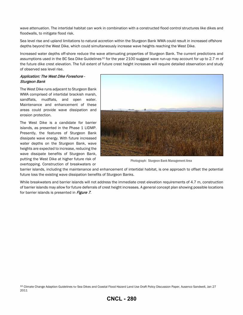
wave attenuation. The intertidal habitat can work in combination with a constructed flood control structures like dikes and floodwalls, to mitigate flood risk.
Sea level rise and upland limitations to natural accretion within the Sturgeon Bank WMA could result in increased offshore depths beyond the West Dike, which could simultaneously increase wave heights reaching the West Dike.
Increased water depths off-shore reduce the wave attenuating properties of Sturgeon Bank. The current predictions and assumptions used in the BC Sea Dike Guidelines10 for the year 2100 suggest wave run-up may account for up to 2.7 m of the future dike crest elevation. The full extent of future crest height increases will require detailed observation and study of observed sea level rise.
Application: The West Dike Foreshore - Sturgeon Bank
The West Dike runs adjacent to Sturgeon Bank WMA comprised of intertidal brackish marsh, sandflats, mudflats, and open water. Maintenance and enhancement of these areas could provide wave dissipation and erosion protection.
The West Dike is a candidate for barrier islands, as presented in the Phase 1 LIDMP. Presently, the features of Sturgeon Bank dissipate wave energy. With future increased water depths on the Sturgeon Bank, wave heights are expected to increase, reducing the wave dissipate benefits of Sturgeon Bank, putting the West Dike at higher future risk of overtopping. Construction of breakwaters or barrier islands, including the maintenance and enhancement of intertidal habitat, is one approach to offset the potential future loss the existing wave dissipation benefits of Sturgeon Banks.
While breakwaters and barrier islands will not address the immediate crest elevation requirements of 4.7 m, construction of barrier islands may allow for future deferrals of crest height increases. A general concept plan showing possible locations for barrier islands is presented in Figure 7.
10 Climate Change Adaption Guidelines for Sea Dikes and Coastal Flood Hazard Land Use Draft Policy Discussion Paper, Ausenco Sandwell, Jan 27 2011
Photograph: Sturgeon Bank Management Area
CNCL - 280
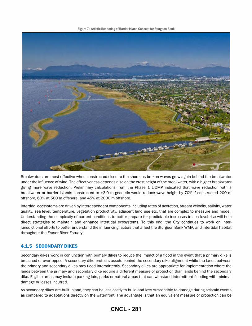
Figure 7: Artistic Rendering of Barrier Island Concept for Sturgeon Bank
Breakwaters are most effective when constructed close to the shore, as broken waves grow again behind the breakwater under the influence of wind. The effectiveness depends also on the crest height of the breakwater, with a higher breakwater giving more wave reduction. Preliminary calculations from the Phase 1 LIDMP indicated that wave reduction with a breakwater or barrier islands constructed to +3.0 m geodetic would reduce wave height by 70% if constructed 200 m offshore, 60% at 500 m offshore, and 45% at 2000 m offshore.
Intertidal ecosystems are driven by interdependent components including rates of accretion, stream velocity, salinity, water quality, sea level, temperature, vegetation productivity, adjacent land use etc. that are complex to measure and model. Understanding the complexity of current conditions to better prepare for predictable increases in sea level rise will help direct strategies to maintain and enhance intertidal ecosystems. To this end, the City continues to work on inter-jurisdictional efforts to better understand the influencing factors that affect the Sturgeon Bank WMA, and intertidal habitat throughout the Fraser River Estuary.
4.1.5 SECONDARY DIKES
Secondary dikes work in conjunction with primary dikes to reduce the impact of a flood in the event that a primary dike is breached or overtopped. A secondary dike protects assets behind the secondary dike alignment while the lands between the primary and secondary dikes may flood intermittently. Secondary dikes are appropriate for implementation where the lands between the primary and secondary dike require a different measure of protection than lands behind the secondary dike. Eligible areas may include parking lots, parks or natural areas that can withstand intermittent flooding with minimal damage or losses incurred.
As secondary dikes are built inland, they can be less costly to build and less susceptible to damage during seismic events as compared to adaptations directly on the waterfront. The advantage is that an equivalent measure of protection can be
CNCL - 281
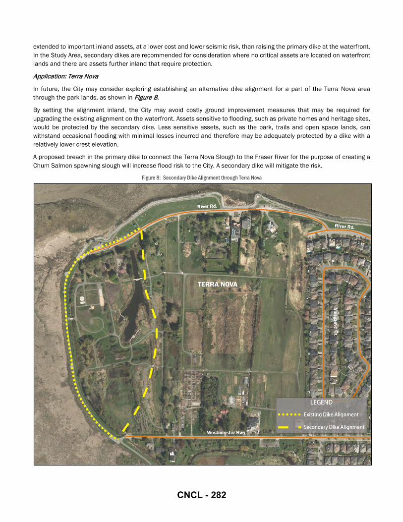
extended to important inland assets, at a lower cost and lower seismic risk, than raising the primary dike at the waterfront. In the Study Area, secondary dikes are recommended for consideration where no critical assets are located on waterfront lands and there are assets further inland that require protection.
Application: Terra Nova
In future, the City may consider exploring establishing an alternative dike alignment for a part of the Terra Nova area through the park lands, as shown in Figure 8.
By setting the alignment inland, the City may avoid costly ground improvement measures that may be required for upgrading the existing alignment on the waterfront. Assets sensitive to flooding, such as private homes and heritage sites, would be protected by the secondary dike. Less sensitive assets, such as the park, trails and open space lands, can withstand occasional flooding with minimal losses incurred and therefore may be adequately protected by a dike with a relatively lower crest elevation.
A proposed breach in the primary dike to connect the Terra Nova Slough to the Fraser River for the purpose of creating a Chum Salmon spawning slough will increase flood risk to the City. A secondary dike will mitigate the risk.
Figure 8: Secondary Dike Alignment through Terra Nova
CNCL - 282

4.2 AREA SPECIFIC ADAPTATIONS
For the purposes of the master plan, an area specific adaptation is a structural adaptation that can achieve the target 4.7 m crest height, with consideration for a future increase to 5.5 m. This section outlines the preferred area specific adaptation measures for each of the thirteen design areas.
The recommended approaches to area specific adaptations includes: widen footprint to land or water side; raise in place / constrained dike; permanent floodwall; demountable floodwall.
Widen Footprint to Land or Water Side
Dikes are the most common form of structural flood protection. Lulu Island is currently protected by a perimeter ring dike, with floodwalls or alternative protections at some sites. In the Study Area, improvements to the existing dike should be pursued wherever possible.
As per the typical dike sections presented in Appendix F, the typical City dike upgrade cross-section consists of a 2:1 slope on the water side, and a 3:1 slope on the land side11. Raising a dike by 1 m then triggers a 5 m horizontal space requirement (assuming the standard slopes are applied). Land side dike expansions can be challenging where the footprint is constrained by existing buildings, infrastructure, drainage ditches, or RMA’s at the toe. Where a dike’s land side toe is heavily constrained, a standard dike can be raised by widening its footprint onto the water side.
While shoreline habitat within the Fraser River Estuary will generally have a higher habitat value, and expansion into this area should be avoided, this may not always be the case. Implementation of area specific flood protection strategies will have an environmental impact regardless of the strategy put forth for a given area. Environmental assessments and valuation will be undertaken in the design construction phase, where possible habitat impact will be avoided. Where impact cannot be avoided, efforts will be made to mitigate, and if necessary compensate for impact following a net gain approach.
Raise in Place / Constrained Dike
Where dike expansion is constrained on both the land and water sides, it may be possible to raise a dike within its existing footprint, creating a constrained dike. This may be achieved by introducing a retaining wall on one or both sides. In Richmond, RMA’s, development and infrastructure may abrupt to the landside of the dike, and intertidal habitat or marine infrastructure may be on the water side of the dike, meaning the dike may have constraints on both sides. In the Study Area, raising the dike in place can be pursued to minimize impacts on adjacent lands.
Permanent Floodwall
A floodwall is a constructed barrier designed to hold back flood waters. In the Study Area, floodwalls can be implemented where space is limited and a dike would interfere with other land uses or infrastructure, such as existing buildings. Floodwalls may also be preferable to a dike where access to the water is required for economic activity, such as fishing or shipping. Generally, where feasible, earth fill trapezoidal dikes are preferable as they generally have lower costs, they are easier to maintenance, they are more reliable and easier to repair in emergency situations.
Demountable Floodwall
In areas where waterfront access is desired, demountable flood barriers can be constructed so that the barrier is erected only when required, during storm events. Regular access to the waterfront is maintained otherwise. This adaptation may be applied in the Study Area at industrial sites or marinas, where activities require amenities directly on the waterfront that cannot be set back behind a floodwall or dike. Where possible, this form of dike is avoided due to their higher costs, mobilization requirements, and reliability concerns.
Parsons assessed each potential dike adaptation strategy based on the considerations outlined in Section 3. A summary of the recommendations for each design area is provided in Table 5. Key issues and opportunities to be considered when implementing the recommended adaptations are presented for each design area in Section 4.2.1 through Section 4.2.13.
11 Typical Cross Section River Dike Upgrade, City Drawing Mb-98, Golder Associates, 2008
CNCL - 283

Table 5: Recommended Area Specific Adaptations FLOOD PROTECTION SEGMENT RECOMMENDATION
WEST DIKE
Seafair Raise the dike on the existing alignment. Additional studies required to quantify drainage impacts of land side expansion, habitat impacts and costs associated with water side or land side expansion, and long term resiliency of a constrained dike solution.
Terra Nova
Raise the dike on the existing alignment. Additional studies required to quantify drainage impacts of land side expansion, habitat impacts and costs associated with water side or land side expansion, and long term resiliency of a constrained dike solution. Alternatively, consider routing a secondary dike inland through Terra Nova Rural Park, in lieu of raising the primary dike at the waterfront.
NORTH DIKE Thompson Terra Nova Raise the dike on the existing alignment with land side expansion. Plan for the long-term raising of River Road.
Thompson Dover Raise the dike on the existing alignment with land side expansion. Plan to raise River Road.
Oval Existing area generally redeveloped as a superdike scenario (elevations from 4.0 to 4.5m). Future raisings to 5.5 m can take place on the existing alignments and integrate into the adjacent landscaping.
City Centre 1 Raise a dike with land side expansion. Consider creation of a set-back dike and inland raising (superdike) in conjunction with the future Middle Arm Waterfront Park construction.
City Centre 2 Raise the dike on the existing alignment with land side expansion in conjunction with redevelopment. Ensure any interim dike upgrades are compatible with the long term strategy of constructing superdikes.
Duck Island River Rock Implement approved development plans. Plan for temporary dike to protect City assets if required to address sea level rise and climate change prior to implementation of the approved strategy at the Duck Island or River Rock Casino sites.
Industrial Raise the dike on the existing alignment. Site specific solutions may be required at the Fraser River Terminal site. Plan for temporary dike along the alternate alignment if required to address sea level rise and climate change prior to implementation of a strategy at the Fraser River Terminal site.
Bridgeport Tait Existing area generally redeveloped as a superdike scenario (elevation 4.7m). Future raisings to 5.5 m can take place on the existing alignments and integrate into the adjacent landscaping.
Industrial North East 1
Raise the dike on the existing alignment. Land acquisition may be required to facilitate construction of a trapezoidal dike (through redevelopment or otherwise). Implementation of a temporary floodwall adjacent to the waterfront lots may be required in advance of a permanent adaptation to address sea level rise and climate change. Consider Bath Slough Revitalization Initiative for future designs.
Industrial North East 2 Raise the dike on the existing alignment. Additional studies required to quantify drainage, habitat impacts, and costs associated with land side expansion of a trapezoidal dike. A constrained land side slope may be required to integrate with the existing drainage infrastructure. Consider Bath Slough Revitalization Initiative for future designs.
Industrial North East 3 Raise the dike on the existing alignment. Additional studies required to quantify drainage, habitat impacts, and costs associated with land side expansion of a trapezoidal dike. A constrained land side slope may be required to integrate with the existing drainage infrastructure.
CNCL - 284

4.2.1 SEAFAIR
The Seafair design area consists of established residential neighbourhoods of single family homes and townhouse complexes. On the foreshore, lands are undeveloped as is the case for the entirety of Sturgeon Bank. The Quilchena Golf & Country Club makes up the northern third of the plan; it sits entirely on Agricultural Land Reserve (ALR) lands. No major changes to the Seafair waterfront are identified in the OCP.
The preferred adaptation is to raise the dike on its existing alignment. Expansions to either side are constrained by environmental and infrastructure factors. These should be evaluated at the time an adaptation project is proposed to inform a detailed design that will best balance the considerations outlined in Section 3.
Barrier islands may be considered to reduce wave run-up and mitigate the need for future dike crest increases, as discussed in Section 4.1.4.
If ditches at the toe of the dike are to be filled, the associated loss of stormwater storage and conveyance may need to be compensated with underground pipes or alternative systems. Ditches may be designated as RMA’s. Associated restrictions to alterantions should be investigated when dike adaptations proceed to design and construction. Revised drainage plans must be compatible with local pump stations.
The Williams Road pump station was upgraded in 2013. The dike crest in the vicinity of the pump station is higher than adjacent lands. The pump station is not anticipated to pose special requirements for raising the dike on adjacent lands, however raising the dike crest over the pump station may increase the loading on this infrastructure. Dike adaptation projects that include raising the dike crest over the pump station should consider the pump station’s structural and operational needs, including access.
LOCATION:
Williams Road to Granville Avenue
RECOMMENDATION:
Raise the dike on the existing alignment. Additional studies required to quantify drainage impacts of land side expansion, habitat impacts and costs associated with water side or land side expansion, and long term resiliency of a constrained dike solution.
ENVIRONMENTAL CONSIDERATIONS:
ENMS Strategy Area • West Dike • Traditional
Neighbourhood ESA Habitat Type • Intertidal • Shoreline
FREMP Data • Red-coded
RMA Presence • 5m RMA Presence
PHOTOGRAPH:
West Dike, facing north at Williams Road Pump Station
CNCL - 285

4.2.2 TERRA NOVA
The Terra Nova area is primarily recreational and agricultural including small, low density areas of single family homes. Recreational and natural areas include the Quilchena Golf & Country Club and Terra Nova Rural Park. The park has extensive natural areas with trails and observation decks at the slough and wetland areas. A large children's play structure, the Adventure Play Environment, opened in 2014 at the northwest corner of the park. No major changes to the waterfront or parklands are identified in the OCP for this design area. The entire park is identified as conservation lands within the OCP.
The open space provides a unique setting within the Study Area to consider both waterfront adaptations at the existing primary dike, or a secondary dike alignment through the park. For more information on the secondary dike option, refer to Section 4.1.5. Barrier islands may be considered for implementation on Sturgeon Bank to reduce wave run-up and avoid the need for future dike crest increases, as discussed in Section 4.1.4. Opportunities to create intertidal habitat areas in the park may be pursued when dike adaptations proceed.
The historic Terra Nova Cannery site is present on the north side of the park, in front of the private homes on River Road within the park. There are no visible remains of the cannery, except the shoreline recedes inwards around the former cannery’s boundaries. Heritage status and associated restrictions to local alterations should be investigated when dike upgrades at the waterfront are proposed. Sheet pile may need to be considered for the segment adjacent to the Cannery site to minimize impacts.
LOCATION:
Granville Avenue to Terra Nova Rural Park
RECOMMENDATION:
Raise the dike on the existing alignment. Additional studies required to quantify drainage impacts of land side expansion, habitat impacts and costs associated with water side or land side expansion, and long term resiliency of a constrained dike solution. Alternatively, consider routing a secondary dike inland through Terra Nova Rural Park, in lieu of raising the primary dike at the waterfront.
ENVIRONMENTAL CONSIDERATIONS:
ENMS Strategy Area • West Dike
ESA Habitat Type • Intertidal • Shoreline
FREMP Data • Red-coded
RMA Presence • 5 m & 15m RMA
Presence
PHOTOGRAPH:
West Dike, facing north at Terra Nova Rural Park
CNCL - 286

4.2.3 THOMPSON TERRA NOVA
The Thompson Terra Nova design area is residential, with recreational uses between River Road and the waterfront in the form of the dike trail and surrounding open space. The residential areas consist primarily of single family homes. No major changes to the Thompson Terra Nova design area are identified in the OCP.
The existing dike is situated between the Middle Arm of the Fraser River and River Road. Future expansions in some areas will be challenging due to the lack of space. Raising River Road will help with future dike crest elevation increases; however, will be challenging to implement.
Single family homes have driveway access from River Road throughout the design area. Individual lots are anticipated to be incrementally raised as they are redeveloped, however, this will take numerous decades to occur.
LOCATION:
Terra Nova Rural Park to McCallan Road
RECOMMENDATION:
Raise the dike on the existing alignment with land side expansion. Plan for the long-term raising of River Road.
ENVIRONMENTAL CONSIDERATIONS:
ENMS Strategy Area • Fraser River • Traditional
Neighbourhood ESA Habitat Type • Intertidal • Shoreline
FREMP Data • Red-coded
RMA Presence • None
PHOTOGRAPH:
North Dike, facing east near Terra Nova Rural Park entrance
CNCL - 287

4.2.4 THOMPSON DOVER
The Thompson Dover design area includes a City works yard and recycling facility, as well as mid-rise multi-family residential complexes. Recreational uses exist between River Road and the waterfront in the form of the dike trail and surrounding open space. Within the Thompson Dover design area, only the City works yard has driveway access to River Road. No major changes to the Thompson Dover design area are identified in the OCP. It is anticipated that the City works yard will be redeveloped to residential uses consistent with the surrounding neighbourhood at some point in the future.
It would be advantageous to raise River Road and assist in future land and dike crest increases in the long term. The multi-family residential lands were raised much higher than River Road when these sites were developed. Raising River Road at this location would not have the same access challenges as the Thompson Terra Nova area as there is no driveway access and the buildings are already on high land. River Road may be raised to the dike crest elevation on this section at any time. It would be advantageous to do a longer segment of River Road together, thus raising the road here should proceed concurrently with raising River Road in the Thompson Terra Nova design area to the west. Raising River Road along the City works yard may be considered concurrently with redevelopment of the site in the event that this site is redeveloped.
Issues and opportunities with raising River Road are further discussed in Section 4.3.2.
LOCATION:
McCallan Road to No. 2 Road Bridge
RECOMMENDATION:
Raise the dike on the existing alignment with land side expansion. Plan for the long-term raising of River Road.
ENVIRONMENTAL CONSIDERATIONS:
ENMS Strategy Area • Fraser River • City Centre
ESA Habitat Type • Intertidal • Shoreline
FREMP Data • Red-coded
RMA Presence • None
PHOTOGRAPH:
North Dike, facing east at Lynas Lane
CNCL - 288

4.2.5 OVAL
Within the Oval design area, the River Road alignment has been relocated south of development to the former rail corridor. The dike trail is part of a wide landscaped area abutting high rise condos. Redevelopment of the Oval design area began in advance of the 2010 Vancouver Winter Olympics, for which the Richmond Olympic Oval skating and fitness centre was built. The adjacent sites have since been redeveloped as well. The majority of these lands were filled to the dike crest elevation when the dike was raised in conjunction with site redevelopment. This design area is considered complete for the time being as the dike crest elevations vary from 4.0 m to 4.5 m, which is within range of the current 4.7 m target dike crest elevation.
There is one existing building directly west of the Dinsmore Bridge, forming the one remaining section of this design area to be raised. As this building has been set back from the waterfront, there is land available to raise the dike by widening the footprint to the land side at this site. This option may be pursued when this segment of River Road is decommissioned and relocated to the former rail corridor inland.
LOCATION:
No. 2 Road Bridge to Dinsmore Bridge
RECOMMENDATION:
Existing area generally redeveloped as a superdike scenario (elevations from 4.0 to 4.5m). Future raisings to 5.5m can take place on the existing alignments and integrate into the adjacent landscaping.
ENVIRONMENTAL CONSIDERATIONS:
ENMS Strategy Area • Fraser River • City Centre
ESA Habitat Type • Intertidal • Shoreline
FREMP Data • Red-coded
RMA Presence • 5 m & 15 m RMA
Presence
PHOTOGRAPH:
North Dike, facing east at the Richmond Oval
CNCL - 289
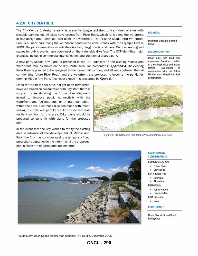
4.2.6 CITY CENTRE 1
The City Centre 1 design area is is presently long-established office industrial sites with sizeable parking lots. All sites have access from River Road, which runs along the waterfront in this design area. Marinas exist along the waterfront. The existing Middle Arm Waterfront Park is a linear park along the waterfront constructed concurrently with the Olympic Oval in 2009. The park’s amenities include the dike trail, playgrounds, and piers. Outdoor seating and stages for public events have been inset on the water side dike face. The OCP identifies major changes, including commercial intensification and creation of a large park.
A new park, Middle Arm Park, is proposed in the OCP adjacent to the existing Middle Arm Waterfront Park, as shown on the City Centre Area Plan presented in Appendix A. The existing River Road is planned to be realigned to the former rail corridor, and all lands between the rail corridor (the future River Road) and the waterfront are proposed to become the parklands forming Middle Arm Park. A concept sketch12 is presented in Figure 9.
Plans for the new park have not yet been formalized; however, based on consultation with City staff, there is support for establishing the future dike alignment inland to improve public connectivity with the waterfront, and facilitate creation of intertidal habitat within the park. A set-back dike combined with inland raising to create a superdike would provide the most resilient solution for this area. Dike plans should be prepared concurrently with plans for the proposed park.
In the event that the City wishes to fortify the existing dike in advance of the development of Middle Arm Park, the City may consider raising a temporary flood protection adaptation in the interim until the proposed park’s plans are finalized and implemented.
12 Middle Arm Open Space Master Plan Concept, PFS Studio, December 2006
LOCATION:
Dinsmore Bridge to Cambie Road
RECOMMENDATION:
Raise dike with land side expansion. Consider creation of a set-back dike and inland raising (superdike) in conjunction with the future Middle Arm Waterfront Park construction.
ENVIRONMENTAL CONSIDERATIONS:
ENMS Strategy Area • Fraser River • City Centre
ESA Habitat Type • Intertidal • Shoreline
FREMP Data • Yellow-coded • Green-coded
RMA Presence • None
PHOTOGRAPH:
North Dike at Gilbert Road, facing east
Figure 9: 2006 Concept Plan for the Proposed Middle Arm Park
CNCL - 290
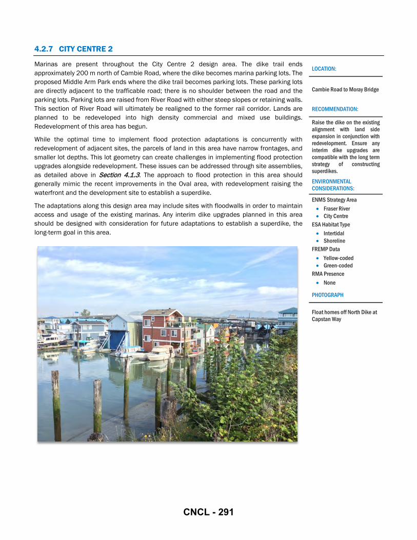
4.2.7 CITY CENTRE 2
Marinas are present throughout the City Centre 2 design area. The dike trail ends approximately 200 m north of Cambie Road, where the dike becomes marina parking lots. The proposed Middle Arm Park ends where the dike trail becomes parking lots. These parking lots are directly adjacent to the trafficable road; there is no shoulder between the road and the parking lots. Parking lots are raised from River Road with either steep slopes or retaining walls. This section of River Road will ultimately be realigned to the former rail corridor. Lands are planned to be redeveloped into high density commercial and mixed use buildings. Redevelopment of this area has begun.
While the optimal time to implement flood protection adaptations is concurrently with redevelopment of adjacent sites, the parcels of land in this area have narrow frontages, and smaller lot depths. This lot geometry can create challenges in implementing flood protection upgrades alongside redevelopment. These issues can be addressed through site assemblies, as detailed above in Section 4.1.3. The approach to flood protection in this area should generally mimic the recent improvements in the Oval area, with redevelopment raising the waterfront and the development site to establish a superdike.
The adaptations along this design area may include sites with floodwalls in order to maintain access and usage of the existing marinas. Any interim dike upgrades planned in this area should be designed with consideration for future adaptations to establish a superdike, the long-term goal in this area.
LOCATION:
Cambie Road to Moray Bridge
RECOMMENDATION:
Raise the dike on the existing alignment with land side expansion in conjunction with redevelopment. Ensure any interim dike upgrades are compatible with the long term strategy of constructing superdikes.
ENVIRONMENTAL CONSIDERATIONS:
ENMS Strategy Area • Fraser River • City Centre
ESA Habitat Type • Intertidal • Shoreline
FREMP Data • Yellow-coded • Green-coded
RMA Presence • None
PHOTOGRAPH
Float homes off North Dike at Capstan Way
CNCL - 291
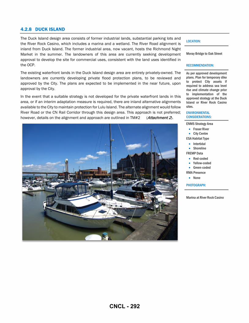
4.2.8 DUCK ISLAND
The Duck Island design area consists of former industrial lands, substantial parking lots and the River Rock Casino, which includes a marina and a wetland. The River Road alignment is inland from Duck Island. The former industrial area, now vacant, hosts the Richmond Night Market in the summer. The landowners of this area are currently seeking development approval to develop the site for commercial uses, consistent with the land uses identified in the OCP.
The existing waterfront lands in the Duck Island design area are entirely privately-owned. The landowners are currently developing private flood protection plans, to be reviewed and approved by the City. The plans are expected to be implemented in the near future, upon approval by the City.
In the event that a suitable strategy is not developed for the private waterfront lands in this area, or if an interim adaptation measure is required, there are inland alternative alignments available to the City to maintain protection for Lulu Island. The alternate alignment would follow River Road or the CN Rail Corridor through this design area. This approach is not preferred; however, details on the alignment and approach are outlined in TM#2 (Attachment 2).
LOCATION:
Moray Bridge to Oak Street
RECOMMENDATION:
As per approved development plans. Plan for temporary dike to protect City assets if required to address sea level rise and climate change prior to implementation of the approved strategy at the Duck Island or River Rock Casino sites.
ENVIRONMENTAL CONSIDERATIONS:
ENMS Strategy Area • Fraser River • City Centre
ESA Habitat Type • Intertidal • Shoreline
FREMP Data • Red-coded • Yellow-coded • Green-coded
RMA Presence • None
PHOTOGRAPH:
Marina at River Rock Casino
CNCL - 292

4.2.9 INDUSTRIAL
The Industrial design area includes industrial areas and parking lots. The Fraser River Terminal and a BC Hydro power station are located here. River Drive is aligned south of these sites, set back from the waterfront. These lands are anticipated to be industrial uses for the foreseeable future, as noted in the OCP.
The North Arm Bridge carrying the Canada Line and a bikeway was constructed in this design area in 2009 with ample clearance for dike works beneath the bridge deck. At the detailed design stage, dike works would need to be verified for confirmation that the footings can withstand additional loading without risk of settling, or any other risks that may compromise the bridge structure.
Adaptations in this area are constrained by existing waterfront development and uses. This industrial area includes the Fraser River Terminal - a shipping port and ship repair centre – as well as the BC Hydro Kidd #2 Substation. This area is anticipated to be industrial for the foreseeable future. Because waterfront lands are constrained by private industrial uses, the City may consider pursuing a temporary adaptation in the interim until the industrial sites are redeveloped. A temporary structure along the River Drive alignment may be considered. This approach is not preferred; however, details on the alignment and approach are outlined in TM#2 (Attachment 2).
LOCATION:
Oak Street Bridge to No. 4 Road
RECOMMENDATION:
Raise the dike on the existing alignment. Site specific solutions may be required at the Fraser River Terminal site. Plan for temporary dike along the alternate alignment if required to address sea level rise and climate change prior to implementation of a strategy at the Fraser River Terminal site.
ENVIRONMENTAL CONSIDERATIONS:
ENMS Strategy Area • Fraser River • City Centre
ESA Habitat Type • Intertidal • Shoreline
FREMP Data • Red-coded • Green-coded
RMA Presence • None
PHOTOGRAPH:
North Dike, west of Fraser River Terminal
CNCL - 293
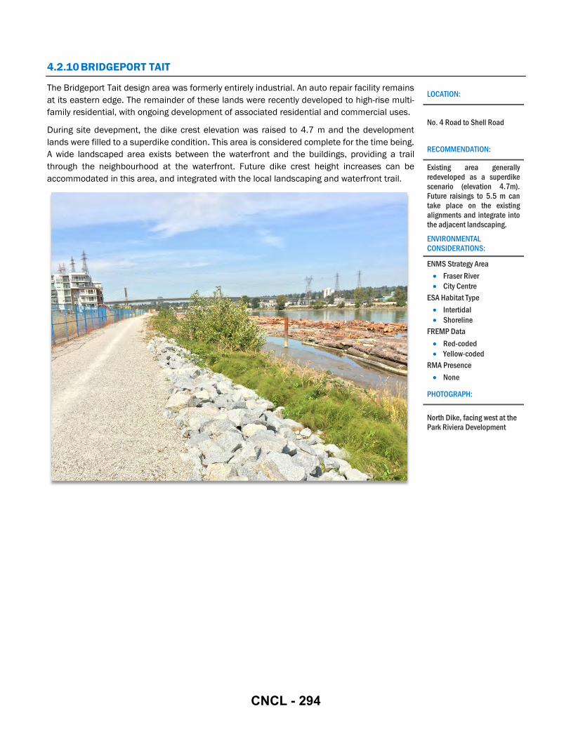
4.2.10 BRIDGEPORT TAIT
The Bridgeport Tait design area was formerly entirely industrial. An auto repair facility remains at its eastern edge. The remainder of these lands were recently developed to high-rise multi-family residential, with ongoing development of associated residential and commercial uses.
During site devepment, the dike crest elevation was raised to 4.7 m and the development lands were filled to a superdike condition. This area is considered complete for the time being. A wide landscaped area exists between the waterfront and the buildings, providing a trail through the neighbourhood at the waterfront. Future dike crest height increases can be accommodated in this area, and integrated with the local landscaping and waterfront trail.
LOCATION:
No. 4 Road to Shell Road
RECOMMENDATION:
Existing area generally redeveloped as a superdike scenario (elevation 4.7m). Future raisings to 5.5 m can take place on the existing alignments and integrate into the adjacent landscaping.
ENVIRONMENTAL CONSIDERATIONS:
ENMS Strategy Area • Fraser River • City Centre
ESA Habitat Type • Intertidal • Shoreline
FREMP Data • Red-coded • Yellow-coded
RMA Presence • None
PHOTOGRAPH:
North Dike, facing west at the Park Riviera Development
CNCL - 294

4.2.11 INDUSTRIAL NORTH EAST 1
The Industrial NE 1 design area is entirely industrial, and no major changes are outlined in the OCP. Limited space is available in this design area as River Road is either directly on the waterfront or confined by developed lots. Where River Road is adjacent to the waterfront, it will need to be raised concurrently with dike works to meet the target dike crest elevation with a standard trapezoidal cross-section. This may impact driveway access to the lots south of River Road. An interim constrained land side dike toe may be required to mitigate impacts to adjacent lots in the interim until redevelopement and land raising occurs.
A number of small businesses operate on a narrow strip of land between River Road and the waterfront. These lands, approximately 2 ha, are privately owned. The City may consider acquiring these lands to implement diking in this area. The acquisition of approximately 2 ha of private lands north of Simpson Road may add significant costs to diking in this area.
A floodwall may be considered for this section of the design area as an interim solution in advance of the City implementing a permanent trapezoidal dike adaptation. Any interim solutions will require cooperation with the existing landowners. Outside this section, there are lands available from the River Road ROW to the shore to raise the existing dike. At the detailed design stage, if lands are too highly constrained to expand the dike footprint, the City may also consider acquiring additional lands from the parking lots on the south side of River Road.
The Industrial North East 1 LIDMP Study Area is bounded by Bath Slough. Through the Bath Slough Revitalization Initiative, adopted in 2014, the City has conducted a number of innovative ecological initiatives along Bath Slough including water quality improvements, riparian enhancement and native pollinator pasture initiatives. The Bath Slough Revitalization Initiative should be considered in the design and construction phase of diking in this area.
LOCATION:
Shell Road to Bath Slough
RECOMMENDATION:
Raise the dike on the existing alignment. Land acquisition may be required to facilitate construction of a trapezoidal dike (through redevelopment or otherwise). Implementation of a temporary floodwall adjacent to the waterfront lots may be required in advance of a permanent adaptation to address sea level rise and climate change. Consider Bath Slough Revitalization Initiative for future designs.
ENVIRONMENTAL CONSIDERATIONS:
ENMS Strategy Area • Fraser River • Industrial
ESA Habitat Type • Intertidal • Shoreline • Freshwater Wetland
FREMP Data • Yellow-coded • Green-coded
RMA Presence • 15m RMA Presence
PHOTOGRAPH:
North Dike, facing west at No. 5 Road
CNCL - 295

4.2.12 INDUSTRIAL NORTH EAST 2
The Industrial NE 2 design area is entirely industrial. River Road abuts the waterfront. Port Metro Vancouver owns a vacant lot west of the Knight Street Bridge. There are large ditches along the south side of River Road. No major changes to this area are presented in the OCP.
River Road is currently the dike in this design area. There are insufficient lands available north of the road to raise the dike, although the elevation of the entire River Road may be raised. No businesses within this area access the waterfront directly from their lots, therefore maintaining waterfront access for these businesses is not required. Existing drainage on the land side may need to be modified as large ditches are present along River Road.
Public access to the waterfront may be improved by the addition of a trail adjacent to the raised River Road, in compliance with the City’s long term vision of a connected trail system at the waterfront of the entire island.
The Industrial North East 2 LIDMP Study Area is bounded by the Bath Slough. Through the Bath Slough Revitalization Initiative, adopted in 2014 the City has conducted a number of innovative ecological initiatives along Bath Slough including water quality improvements; riparian enhancement and native pollinator pasture initiatives. The Bath Slough Revitalization Initiative should be considered in the design construction phase of dike upgrades in this area.
LOCATION:
Bath Slough to Knight Street Bridge
RECOMMENDATION:
Raise the dike on the existing alignment. Additional studies required to quantify drainage, habitat impacts, and costs associated with land side expansion of a trapezoidal dike. A constrained land side slope may be required to integrate with the existing drainage infrastructure. Consider Bath Slough Revitalization Initiative for future designs.
ENVIRONMENTAL CONSIDERATIONS:
ENMS Strategy Area • Fraser River • Industrial
ESA Habitat Type • Intertidal • Shoreline • Freshwater Wetland
FREMP Data • Red-coded • Yellow-coded • Green-coded
RMA Presence • 15m RMA Presence
PHOTOGRAPH:
North Dike, facing east at Bath Slough Pump Station
CNCL - 296

4.2.13 INDUSTRIAL NORTH EAST 3
The Industrial NE 3 design area is entirely industrial. River Road abuts the waterfront and provides access to substantial parking lots for associated industrial sites and businesses. There are large ditches along the south side of River Road. No major changes to this area are presented in the OCP.
River Road is currently the dike in this design area. Large natural areas along the waterfront host mature trees, primarily on the north side of the dike. There is also smaller, less established vegetation along the south side of River Road. It is anticipated that the entire road must be raised to implement dike crest increases.
A lumber yard occupies a substantial part of this design area. The City has a ROW through the site over the River Road alignment, however access is blocked off with gates at either end of the lumber yard site. The waterfront trail is also currently blocked off through this area. If ever this site is redeveloped, dike adaptations may be pursued concurrently. However, no major changes to this industrial area are anticipated in the near future.
LOCATION:
Knight Street Bridge to No. 6 Road
RECOMMENDATION:
Raise the dike on the existing alignment. Additional studies required to quantify drainage, habitat impacts, and costs associated with land side expansion of a trapezoidal dike. A constrained land side slope may be required to integrate with the existing drainage infrastructure.
ENVIRONMENTAL CONSIDERATIONS:
ENMS Strategy Area • Fraser River • Industrial
ESA Habitat Type • Intertidal • Shoreline
FREMP Data • Red-coded • Green-coded
RMA Presence • 15m RMA Presence
PHOTOGRAPH:
Conveyor belt over North Dike at No. 6 Road.
CNCL - 297

4.3 SITE SPECIFIC ADAPTATIONS
Where existing infrastructure conflicts with the recommended flood protection adaptation, a custom design for that site may be required, or the existing infrastructure may be retrofitted to accommodate diking. Infrastructure including but not limited to pump stations, road or railways, bridges or industrial infrastructure may present site-specific constraints that preclude the implementation of the recommended adaptation for the rest of that design area.
Ideally, dike adaptations are pursued when the adjacent lands are redeveloped. Flood protection measures can then be included in the scope of the proposed works. However, existing infrastructure may be suitable for a design life extending far into the future, farther than the City wishes to defer dike adaptations. In these cases, interim adaptations may be pursued.
Site-specific adaptation designs, whether permanent or temporary, should take into account all the considerations listed in Section 3.
4.3.1 BRIDGES
Bridges have unique constraints within a design area. The recommended adaptation for a design area may not be feasible at a bridge site, in which case a site-specific adaptation may be designed to be integrated with the standard adaptation on either side of the bridge.
A list of bridges and the particular constraints that may guide a site-specific adaptation is presented in Table 6 below. Note that the recommended adaptation strategies in the table are recommended based on adaptations proceeding in advance of any bridge upgrades or replacement. If any bridges are to be upgraded or replaced, flood protection measures at the bridge site should be included within the scope of work.
Table 6: Bridge Constraints and Recommended Adaptations
BRIDGE NAME (OWNERSHIP, BRIDGE TYPE)
AREA CONSTRAINTS AND CONDITIONS RECOMMENDED ADAPTATION STRATEGY
1) NO. 2 ROAD BRIDGE (CITY OF RICHMOND, ROAD)
Oval
• Bridge deck is low. • Footings are under the existing dike. • Bridge crosses over River Road. • Bridge crosses over dike trail. • Bike ramp to bridge from dike trail sensitive to grade changes.
Tied to abutments
2) DINSMORE BRIDGE (CITY OF RICHMOND, ROAD)
Oval
• Bridge deck is low. • Footings are under the existing dike. • Bridge crosses over River Road with 4.3m clearance. • Bridge crosses over dike trail.
Tied to abutments
3) MORAY BRIDGE (CITY OF RICHMOND, ROAD)
City Centre 1
• Bridge deck is very low. • Existing dike is inland, not under the bridge. • Bridge does not cross any road or trail. • No waterfront trail currently exists under the bridge. • Existing dike is aligned over the bridge.
Tied to abutments
4) SEA ISLAND CONNECTOR (CITY OF RICHMOND, ROAD)
City Centre 1
• Bridge deck is very low. • Existing dike is inland, not under a bridge. • Bridge does not cross any road or trail. • No waterfront trail currently exists under the bridge. • Existing dike is aligned over the bridge.
Tied to abutments
CNCL - 298
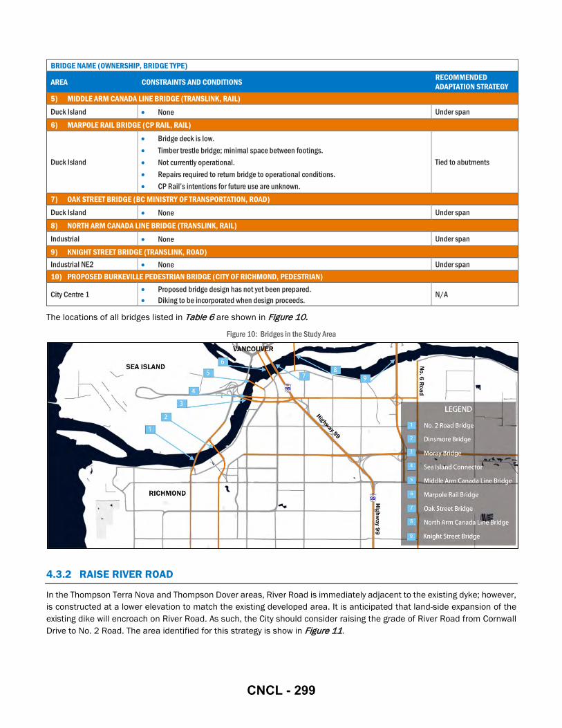
BRIDGE NAME (OWNERSHIP, BRIDGE TYPE)
AREA CONSTRAINTS AND CONDITIONS RECOMMENDED ADAPTATION STRATEGY
5) MIDDLE ARM CANADA LINE BRIDGE (TRANSLINK, RAIL) Duck Island • None Under span 6) MARPOLE RAIL BRIDGE (CP RAIL, RAIL)
Duck Island
• Bridge deck is low. • Timber trestle bridge; minimal space between footings. • Not currently operational. • Repairs required to return bridge to operational conditions. • CP Rail’s intentions for future use are unknown.
Tied to abutments
7) OAK STREET BRIDGE (BC MINISTRY OF TRANSPORTATION, ROAD) Duck Island • None Under span 8) NORTH ARM CANADA LINE BRIDGE (TRANSLINK, RAIL) Industrial • None Under span 9) KNIGHT STREET BRIDGE (TRANSLINK, ROAD) Industrial NE2 • None Under span 10) PROPOSED BURKEVILLE PEDESTRIAN BRIDGE (CITY OF RICHMOND, PEDESTRIAN)
City Centre 1 • Proposed bridge design has not yet been prepared. • Diking to be incorporated when design proceeds.
N/A
The locations of all bridges listed in Table 6 are shown in Figure 10.
Figure 10: Bridges in the Study Area
4.3.2 RAISE RIVER ROAD
In the Thompson Terra Nova and Thompson Dover areas, River Road is immediately adjacent to the existing dyke; however, is constructed at a lower elevation to match the existing developed area. It is anticipated that land-side expansion of the existing dike will encroach on River Road. As such, the City should consider raising the grade of River Road from Cornwall Drive to No. 2 Road. The area identified for this strategy is show in Figure 11.
CNCL - 299
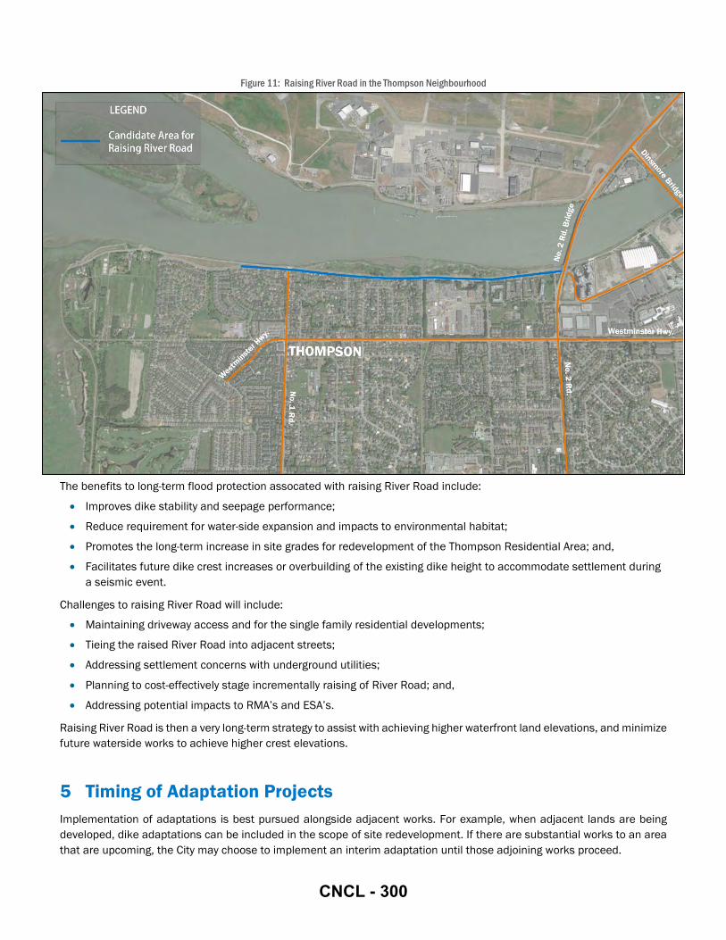
Figure 11: Raising River Road in the Thompson Neighbourhood
The benefits to long-term flood protection assocated with raising River Road include:
• Improves dike stability and seepage performance;
• Reduce requirement for water-side expansion and impacts to environmental habitat;
• Promotes the long-term increase in site grades for redevelopment of the Thompson Residential Area; and,
• Facilitates future dike crest increases or overbuilding of the existing dike height to accommodate settlement during a seismic event.
Challenges to raising River Road will include:
• Maintaining driveway access and for the single family residential developments;
• Tieing the raised River Road into adjacent streets;
• Addressing settlement concerns with underground utilities;
• Planning to cost-effectively stage incrementally raising of River Road; and,
• Addressing potential impacts to RMA’s and ESA’s.
Raising River Road is then a very long-term strategy to assist with achieving higher waterfront land elevations, and minimize future waterside works to achieve higher crest elevations.
5 Timing of Adaptation Projects Implementation of adaptations is best pursued alongside adjacent works. For example, when adjacent lands are being developed, dike adaptations can be included in the scope of site redevelopment. If there are substantial works to an area that are upcoming, the City may choose to implement an interim adaptation until those adjoining works proceed.
CNCL - 300

5.1 REDEVELOPMENT OF SMALL LOTS
Small lots with narrow frontages are highly constrained by grading. There must be adequate lands available to raise a dike immediately to the target crest elevation. In areas where lot sizes are too small to implement adaptations that may immediately achieve the dike crest elevation, lands can be incrementally raised by raising the lots in small intervals each time it is redeveloped. Similarly, the frontage road can be raised by a practical interval whenever substantial road rehabilitation works proceed. This is a very long-term strategy.
The ground elevation of individual lots may be raised as they are redeveloped, however the grading will be constrained by matching neighbouring ground elevations, as well maintaining driveway access to the road. If the road is also raised, then individual lots can be raised higher, however existing lots at relatively low elevations must still have driveway access to the road. This limits the overall height that the frontage road can be raised. Over time, the frontage road and adjoining lots are raised at different times. In this way, the road and surrounding lots are raised in steps. In the very long term, the overall land elevation can be raised to the target dike crest elevation using this strategy. The City may pursue interim adaptations if a greater level of flood protection is deemed to be required before the lands can be raised to the specified elevation.
Where flood protection will be integrated with redevelopment, lot consolidation is preferred to minimize impacts associated with tying in to neighbuoring properties.
5.2 LAND ACQUISITIONS & LEGAL ACCESS
The City may need to acquire property where development is immediately adjacent to the waterfront, and bound on the land side by roads, buildings or other assets. Obtaining a sufficient ROW from some properties for diking may effectively sterilize the lot, leaving insufficient space available for development. In those instances, the City may need to acquire the entire property in order to implement dike adaptations. The riverfront lots between Shell Road and No. 5 Road may be candidates for acquisition when dike upgrades proceed in that area, depending on land requirements to implement dike upgrades.
The City should acquire easements where dikes are being constructed on private property. All adaptations on private lands depend on the City being able to secure legal access to the property in order to maintain them.
5.3 RAISING THE TARGET DIKE CREST ELEVATION
The City should monitor sea level rise to pursue flood protection adaptations when higher dike crest elevations become necessary. Presently, all adaptations will be designed to meet the 4.7 m target crest elevation, with consideration for an increase to 5.5 m. Depending on whether sea level rise predictions materialize, the City may wish to raise the target dike crest elevation.
5.4 INTERIM ADAPTATIONS
Temporary adaptations, such as a demountable floodwall, may be necessary where existing conditions are constrained by existing infrastructure (such as bridges, roads, ditches, or buildings) that cannot be impacted or modified to make way for diking. Temporary adaptations may also be pursued in instances where the City cannot yet secure adequate lands or capital to implement the ultimate adaptation.
The timeline until the ultimate adaptation can be implemented should be considered when allocating resources to temporary works. For example, if the interim adaptation will only be in place for a period of a few months, it it likely not worth investing substantial resources into it. Interim adaptations may be considered if necessitated by sea level rise or any other increase in flood risk.
Compatibility with the ultimate adaptation should be considered in the design of any interim adaptation. An interim adaptation should be easily decommissioned, or able to remain in place indefinitely without interfering with the ultimate
CNCL - 301

adaptation or any other land use. The ultimate adaptations are anticipated to be implemented alongside concurrent waterfront works, as noted in Table 7.
Table 7: Triggers to Implementation of Adaptations
AREA EXISTING SUMMARY OF RECOMMENDED ADAPTATION
TRIGGER TO IMPLEMENTATION OF RECOMMENDED ADAPTATION
Steveston Earthfill Dike Raise Dike on Existing Alignment & Consider Construction of Barrier Islands
City Initiative
Seafair Earthfill Dike Raise Dike on Existing Alignment & Consider Construction of Barrier Islands
City Initiative
Terra Nova Earthfill Dike Raise Dike on Existing Alignment & Consider Construction of Barrier Islands
City Initiative
Thompson Terra Nova Earthfill Dike Raise Dike on Existing Alignment & Plan for Long-term Raising of River Road
River Road is Reconstructed
Thompson Dover Earthfill Dike Raise Dike on Existing Alignment & Plan for Long-term Raising of River Road
River Road is Reconstructed
Oval Superdike Complete N/A
City Centre 1 Earthfill Dike Raise Dike at Waterfront or Set Back & Fill Adjoining Lots to Superdikes
Development of Middle Arm Park
City Centre 2 Earthfill Dike Raise Dike on Existing Alignment & Fill Adjoining Lots to Superdikes
Redevelopment
Duck Island Varies Implement Recommendations of Approved Developer’s Plan
Approval of Developer’s Plan
Industrial Varies Raise Dike on Existing Alignment Redevelopment of Fraser River Terminal
Bridgeport Tait Superdike Complete N/A
Industrial North East 1 Earthfill Dike Raise Dike on Existing Alignment Assembly of Sufficient Lands to Implement Dike Upgrades
Industrial North East 2 Earthfill Dike Raise Dike on Existing Alignment Rehabilitation of River Road or Redevelopment of Industrial Sites
Industrial North East 3 Earthfill Dike Raise Dike on Existing Alignment Rehabilitation of River Road or Redevelopment of Industrial Sites
6 Implementation Opportunities Dike upgrades are best undertaken alongside alterations to adjacent lands and infrastructure. In addition to the examples of concurrent infrastructure development noted in the sections above, dike adaptations may present opportunities to implement projects strategically to accomplish other City goals.
6.1 WATERFRONT TRAIL SYSTEM
The City’s Parks Planning and Design (Parks) department has identified a goal to improve public access to the waterfront. Recreational trails and linear parks should be considered wherever dikes are modified. Even where waterfront trails are
CNCL - 302

already present, there may be an opportunity to increase waterfront access by improving trails with ramps or paved surfaces. Dike trails should remain accessible to people using mobility aids, such as wheelchairs or strollers.
The Parks department’s preference is to have a trail directly adjacent to the water, without any rerouting inland, even if this means trails are sometimes flooded.
6.2 INTERTIDAL ZONES
Dike adaptations that proceed alongside the development of waterfront parks may be suited to the concurrent development of intertidal zones, to create additional habitat. The local ecosystem’s productivity may be increased by providing a rich riparian environment. These intertidal zones may be integrated with the typical foreshore rip rap or other erosion protection by insetting habitat at lower elevations to be closer to the daily water level, and flooded during high water events. Projects incorporating the development of intertidal habitat may be designated as compensation sites for alterations required in environmentally sensitive areas.
6.3 HABITAT BANKING
As the Study Area lies within intertidal, shoreline and upland riparian habitat, environmental impact may be unavoidable. Environmental assessments and valuation will be undertaken in the design construction phase, where possible habitat impact will be avoided. Where impact cannot be avoided, efforts will be made to mitigate, and if necessary compensate for impact following a net gain approach. To achieve a net gain approach to compensation the City may consider establishing a formal habitat banking program. Habitat banking guidelines should articulate appropriate compensation ratios by habitat type, monitoring periods and success measures for created or enhanced habitat. Additionally a hierarchy of compensation options may be considered that replaces habitat types in order of priority as follows:
• Create or increase productive capacity of like for like habitat within the same ecological unit;
• Create or increase the productive capacity of unlike habitat in the same ecological unit; and
• Create or increase the projective capacity of habitat in a different ecological unit.
Habitat credits could be applied to multiple projects, or stored for future dike works. A formal habitat banking program may assist with the implementation of long term flood protection infrastructure upgrade programs.
7 Recommendations Key recommendations for the Phase 2 LIDMP Study Area are outlined as follows:
1. Plan to raise the existing dike on its existing alignment.
The existing dike alignment along the waterfront is established and well defined. There is limited basis to support any major changes to the alignment of the existing dike, thus the recommendations are generally in keeping with traditional dike crest increases, with consideration for area specific constraints and opportunities.
2. Prepare conceptual level designs for the West Dike upgrades and conduct drainage and environmental studies on the alternatives.
Future crest height increases to the West Dike will required landside or waterside expansion. Both will have impacts to either intertidal, or upland riparian habitat. Environmental impacts should be quantified, and an approach of avoid, mitigate, and compensate following a net gain approach should be used to in evaluating the preferred strategy.
Landside expansion will impact drainage infrastructure. Impacts should be quantified to identify potential internal drainage network upgrades required if landside expansion is the preferred alignment.
CNCL - 303
3. Continue to monitor sea level rise.
Design crest height elevations are selected with consideration for climate change and sea level rise predictions. The City should continue to monitor sea level rise and adjust crest height targets and City flood protection police as required to address any changes in predicitons.
4. Plan to establish a habitat banking program for dike improvement projects.
Where impact to habitat cannot be avoided, efforts will be made to mitigate, and if necessary compensate for impacts following a net gain approach. To achieve a net gain approact to compensation, the City may consider establishing a formal habitat banking program. Habitat banking guidelines should outline appropriate compensation ratios by habitat type, monitoring periods, and success measures.
5. Plan for implementation of offshore protection along the West Dike as a response to climate change and sea level rise.
Sea level rise and upland limitations to natural accretion within the Sturgeon Bank WMA could result in increased offshore depths beyond the West Dike, which could simultaneously increase wave heights reaching the West Dike. Offshore barrier islands are one option to consider to dissipate wave energy prior to reaching the west dike, thereby minimizing future dike crest increases.
With appropriate environmental consideration during design and construction, breakwaters and barrier islands can create intertidal habitat, such as sand flats, mud flats, salt marsh and eelgrass beds. These features can assist with erosion and wave attenuation. The intertidal habitat can work in combination with a constructed flood control structures like dikes and floodwalls, to mitigate flood risk.
The City should continue to coordinate with relevant agencies including (Port of Vancouver, Fisheries and Oceans Canada, and others) to research and identify opportunities to improve flood protection and enhance interdital habitats in the Sturgeon Bank WMA and throughout the Fraser River Estuary.
6. Plan to raise River Road in the Thompson neighborhood.
The existing dike in the Thompson Neighborhood is confined by the Fraser River and River Road. Increasing the grade of River Road will improve dike stability and resilence; and minimize requirement to expand the dike into the Fraser River. The City should plan to incrementally raise River Road.
7. Consider aquiring land to accommodate future dike construction between Shell Road and No. 5 Road.
Land acquisition may be required to accommodate construction of a future trapezoidal dike between Shell Road and No. 5 Road. It is anticipated that acquisition will primarily be achieved through redevelopment, however, where redevelopment does not occur; the City may consider opportunistic land purchase to accommodate future dike crest height increases in the area. Plan to complete a conceptual design of the future dike through the constrained area to verify the future dike footprint.
8. Plan for the long-term raising of lands adjacent to and inland of the existing dikes.
Long term raising of land levels has previously been recommended (2008-2031 Flood Protection Strategy). Maximizing the width of raised land adjacent to the river decreases flood and seismic risks by increasing the integrity of the dike. Plan to raise the ground elevation of waterfrount development sites to the prescribed dike crest elevation.
9. Support site assemblies along the waterfront that promote cohesive adaptations for flood protection.
Large developments along the waterfront allow for major improvements to flood protection infrastructure and often result in robust superdike conditions.
CNCL - 304
PARSONS
10. Consider enhanced flood proofing through amendments to the FCL Bylaw
The City's Flood Construction Level (FCL) Bylaw establishes minimum levels to which land needs to be raised.
Amending the FCL bylaw is the recommended area wide strategy to regulate raising ground elevations with redevelopment to improve fl ood protection throughout the Study Area. Plan to conduct an assessment on the implementation of a modified FCL bylaw.
11. Facilitate public access to the waterfront.
Regards,
Integrate new trails and trail improvements with diking projects; provide trails and waterfront recreation areas that are accessible to persons using mobility aids; and, route any new trails along the waterfront instead of rerouting the trail inland.
Alex McBride, P.E . Project Manager
Phil Lobo, P.Eng. Project Reviewer
CNCL - 305