ckeg_day1
DESCRIPTION
CENTUM ENGINEERINGTRANSCRIPT

Yokogawa Engineering AsiaSingapore Training Centre
CS3000 R3 Engineering CourseDay 1

Page.2
Instructor: Ivan ChooEmail:
Lesson:9:00am ~ 4:30pm
Tea Break: 10:00 ~ 10:15am2:45 ~ 3:00pm
Lunch: 11:45am ~ 1:00pm
Introduction
Page.3
Table of Contents
1. CS 3000 System Overview
2. Project Creation
3. Project’s Attribution Utility
4. Project Common Definition
Day 1
Laboratory: Project Creation, Attribution Utility,Common Definition

Page.4
Table of Contents
1. FCS Configuration
2. I/O Module Configuration
3. Software Switches Configuration
4. Message Definition
5. Control Drawing Builder
Day 2
Laboratory: Process I/O Definition, Switches Configuration,Message Definition

Page.5
Table of Contents
1. Regulatory Control
2. Sequence Control
Day 3
Laboratory: Creation of Regulatory Control Function,Creation of Sequence Control Function
Page.6
Table of Contents
1. HIS Configuration
2. Windows Configuration
Day 4
Laboratory: HIS Configuration and Windows Configuration

Page.7
Table of Contents
1. Graphic Builder
Day 5
Laboratory: Graphics Generation

Page.8
Centum CS 3000 System Overview
HIS is mainly used for operation and monitoring:1. Desktop2. Console : Enclosed Display Open Display
ENG: The PC with engineering functions used to perform CENTUM CS 3000 system generation and maintenance management.
FCS performs process control, and manages communication with subsystems such as PLCs.
Refer to Page A-1 & A-2
HISHuman InterfaceStation
FCSField ControlStation
Process I/Os Transmitters, Valves, etc
FIO : Fieldnetwork RIO : Remote I/O

Page.9
System Specifications
System CS 1000 CS 3000
Max. no. of monitoring tags 8000 100 000
Max. no. of stations 24 256
Max. no. of domains 1 16
Max. no. of stations perdomain
HIS (8)FCS (16)
64 (HIS (16) , FCS, BCV, CGW)
Refer to Page A-22

Page.10
Network
Page A-20
Network Vnet VL Net
Transmission Speed 10 Mbps (real-time control bus) 10 Mbps (real –time control bus)
Cable Types 10 Base 2 (for HIS)10 Base 5 (for FCS, CGW, etc)
10 Base 2 cable ( for stations)
Transmission distance 185 m/segment (for 10 Base 2)500 m/segment (for 10 Base 5)
185 m/segment (for 10 Base 2)
Access Method Token Passing Token Passing
Repeater - Coaxial Cable - Optical Fiber
Max. 1.6 km, 8 repeatersMax. 20 km, 4 repeaters
Max. 1.6 km, 8 repeatersMax. 20 km, 4 repeaters
Token Passing is a technique in which only that system can communicate that has token. Token isa sort of control mechanism that gives authority to the system to communicate or use the resourcesof that network. Once the communication is over, the token is passed to next candidate in asequential manner.

Page.11
Domain
Bus Converter: i) Link two domains ii) Link CENTUM CS 3000 system to previous systems (CENTUM CS, CENTUM XL, CENTUM V, CENTUM CS 1000 & µXL)
Domain: A group of stations linked by V net cables. When the no of stations reaches a maximum of 64 in a domain, a new domain has to be started.
Page A-23
Communications Gateway:This links the V net to the Ethernet (to a supervisory PC).By CGW wide area communication function, two CENTUM CS3000 V nets canbe linked in different places using a dedicated telephone line.
Page.12
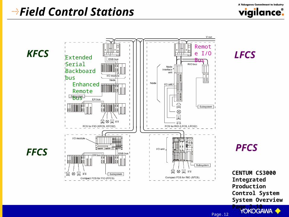
Field Control Stations
Extended Serial Backboard bus
Enhanced Remote bus
Remote I/O BusKFCS
FFCS
LFCS
PFCS
CENTUM CS3000 Integrated Production Control System System Overview Page 2-10

Page.13
Standard Field Control Station for FIOs (KFCS)
Refer to Page A-7
Max no. of nodes: 10
5 nodes
5 nodes

Page.14
Standard Field Control Station for RIOs (LFCS)
Refer to page A-6
Max. no. of nodes: 8
3 nodes3 nodes
Another 2 nodes installed in another cabinet, if required
Page.15
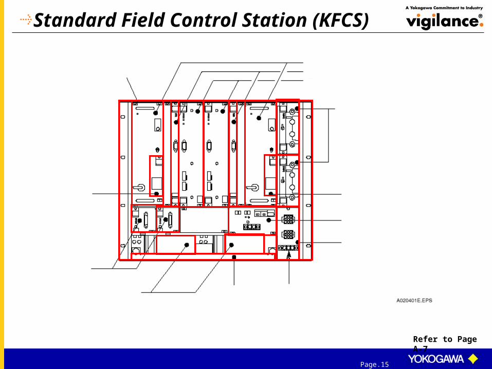
Standard Field Control Station (KFCS)
Refer to Page A-7

Page.16
Standard Field Control Station (LFCS)
Refer to Page A-6

Page.17
Compact Field Control Station for FIOs (FFCS)

Page.18
Compact type FCS (PFCS/SFCS)
Page A-8

Page.19
Setting Domain Number: LFCS/KFCS
Page A-16
To set domain number from 1 to 16Total no. of 1s from bit 4 to bit 8 is odd => Bit 1 = “0”Total no. of 1s from bit 4 to bit 8 is even => Bit 1 = “1”
1
2
3
4
5
6
7
8
0 1
1000
01
10
1 0 0 0 0 1 1 0
2² 2¹
4 + 2 = 6
Total no. of 1s from bit 4 to bit 8 is even.

Page.20
Setting Station Number: LFCS/KFCS
Page A-17
To set station number from 1 to 64Total no. of 1s from bit 2 to bit 8 is odd => Bit 1 = “0”Total no. of 1s from bit 2 to bit 8 is even => Bit 1 = “1”
1
2
3
4
5
6
7
8
0 1
1001
00
01
1 0 0 1 0 0 0 1
24 20
16 + 1 = 17
Total no. of 1s from bit 2 to bit 8 is even.

Page.21
Dual-Redundant Architecture of FCU: KFCS
LFCS same as above except that ESB Bus Interface (SB301) is replaced by RIO Bus Interface(RB301).
Page A-11
Right unit in control
CPU1 & CPU2 perform same control computation
Collator checks computational results from both CPUs
Results match, collator sends data to main memory & ESB bus interface
Error-Correcting Code repairs transient bit inversion errors
Results do not match, collator declares computational error, control right transferred to left unit
Standby unit performs the same computation as control unit, has the capability to take over the control immediately
Error unit performs self-diagnostics, no CPU error implies transient computational error, unit goes to standby state
Standby unit performs same control computation concurrently with control unit; it can take over the control at any point of time without interruption, even for a very short time

Page.22
Dual-Redundant Architecture of FCU: SFCS
Same principle as in KFCS
WDT (Watch Dog Timer) in the processor unit supervises the execution of control transferring, in the event of an abnormality in the processor in control.
PFCS same as above except that Vnet Interface is replaced by VL Net Interface.
Page A-12
The PI/O bus interface has the function to run the PI/O executions on control side and to diagnose the PI/O performance by itself. The same diagnostic function is also running in standby side PI/O bus interface.
When an abnormality occurs in the control side PI/O bus, the control right is immediately switched to the standby side PI/O, thus the PI/O executions may be continued.

Page.23
Dual-Redundant Architecture of FCU: FFCS
If an abnormality is detected in the self-diagnostics of the I/O controller inside the controlling processor module, the control right is transferred to the standby processor module.
Inside the processor modules, faults of the SB buses are diagnosed by accessing each other’s processor module via the SB buses between duplexed processor modules.
If all local nodes are abnormal, it is assumed as an ESB bus failure.
Same principle as in KFCS

Page.24
Test Function
The Test Function is a group of tools (option packages) for efficiently debuggingFCS software created by the user.
Two types of tests :
Page B-1
The Test Functions allow combinations of monitoring/operation and control functionsto be tested before being put into operation. There are two types of test functions: . Virtual tests . Target tests
Test Function Virtual test
Target test I/O disconnection (Use virtual I/O)
Use real I/O

Page.25
Test Function –Virtual Test
Virtual TestVirtual test uses an FCS simulator instead of an actual FCS. The FCS simulator simulates the functions and operation of the FCS and runs under an HIS.
Page B-1

Page.26
Test Function –Target Test
Target TestTarget test uses an actual FCS. When there are no I/O modules and I/O test devices, an FCS input and output can be simulated by using the I/O Disconnect and Wiring Functions.
Page B-2

Page.27
Concurrent Engineering
Using Windows File sharing, several people can share an Engineering database on a network; concurrent engineering is possible.
Page B-2

Page.28
Start Virtual Test Function by :Start Programs YOKOGAWA CENTUM System View
Virtual Test Function

Page.29
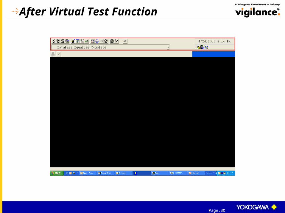
Virtual Test Function
Page.30
After Virtual Test Function

Page.31
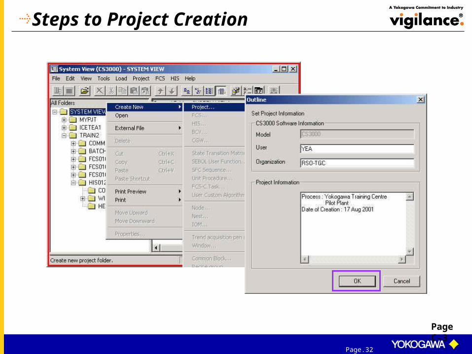
Project
A project is a unit that manages the engineering database of the FCS and the HIS created by the user.
PageC-2
Page.32
Steps to Project Creation
Page C-3

Page.33
Steps to Project Creation
The default location in which to store the project .
Page C-4 ~ Page C-5
LFCS
KFCS
Page.34
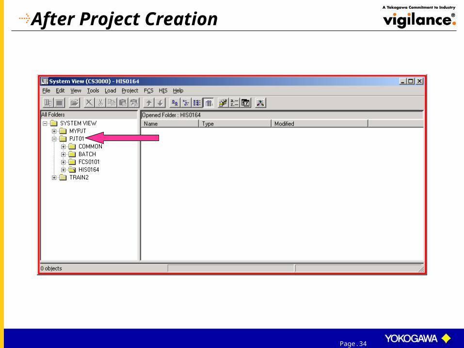
After Project Creation
Page.35
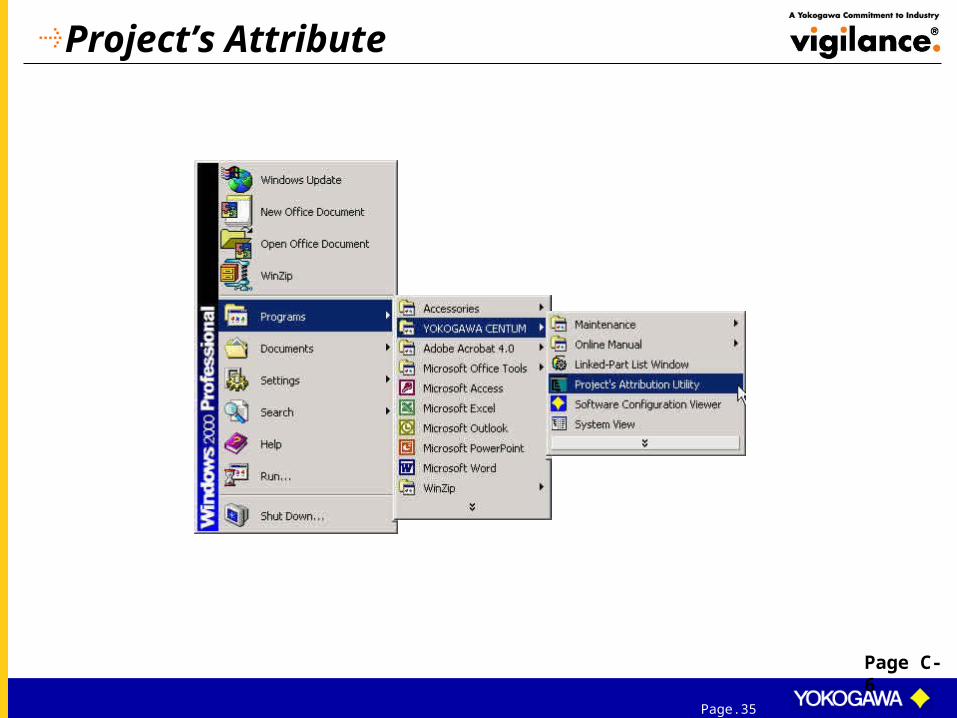
Project’s Attribute
Page C-6

Page.36
Project’s Attribute
Page C-6

Page.37
Project’s Attribute
Page C-6

Page.38
Registering a Project
Select project
Select project attribute

Page.39
Project’s Attribute - Differences
Default Current User-defined
Created the first time when the System View starts
Yes - -
Virtual test with the FCS simulator.
Yes Yes but target test
Yes
Can be downloaded to the FCS of the target system
Yes but off line
Yes but on line No
Can be downloaded to HIS. Yes Yes No
Multiple projects can be created in System View.
No No Yes
Page C-1
When any one of the FCS’s created in default project is successfully downloaded, the attribute changes to a current project.

Page.40
Project Common
User defined

Page.41
Alarm Priority
Designate in the Alarm Priority Builder whether or not the status change is to be displayedin a window upon occurrence of the alarm or upon recovery of the system.
Designate in the Alarm Priority Builder whether or not the status change is to be printed outto a printer upon occurrence of the alarm or upon recovery of the system.
Designate in the Alarm Priority Builder whether or not the status change is to be logged in ahistorical message save file upon occurrence of the alarm or upon recovery of the system.A message logged in a historical message save file can be displayed in a Historical MessageReport window.

Page.42
Alarm Priority

Page.43
Alarm Priority

Page.44
Alarm Processing Table
Alarm processing levels 1- 4 system fixed, 5 – 16 User defined
Alarm status bit 1 – 6 not displayed, system fixed
e.g. NR is assigned with green for alarm processing levels 1-4

Page.45
System-fixed Status CharacterString
Page D-9 & D-10Page D-9 & D-10
The alarm status character strings that are output upon occurrence of the alarm are available for each type of function block. The character string can be confirmed with the system fixed status character string viewer.

Page.46
System-fixed Status CharacterString/ Alarm Processing Table/ Alarm Priority
Page D-9 & D-10

Page.47
Project Common

Page.48
Engineering Unit
Nos.1 to 8 cannot be changed or deleted. Default values are predefined for Nos.9 to 126.
Page D-7
Up to 256 engineering unit symbols can be used for one project.
One engineering unit symbol can be defined with up to six alphanumeric characters and it is case-sensitive
Page.49
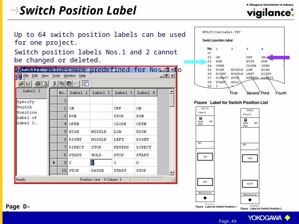
Switch Position Label
Up to 64 switch position labels can be used for one project.
Switch position labels Nos.1 and 2 cannot be changed or deleted.
Default values are predefined for Nos.3 to 13.
Page D-8

Page.50
Project Common

Page.51
Operation MarkAttaching operation mark may temporarily change the write access right on the block during plant operation. There are 64 operation marks available for configuration.
Page D-5 ~ D-6
8 characters can be entered as the text on the label (string)

Page.52
Station Configuration
Overview of the station configured for the project.
Page D-1

Page.53
Project Common

Page.54
User Security
Page D-2 ~ Page D-4
User NameUser GroupPrivilege Levels
Set Automatic User Out TimeAutomatic User Out Time [Hour]Automatic User Out Time [Minute]
Comment
Valid User:

Page.55
User Name
Each user name must be unique, consisting of eight alphanumeric characters or fewer and is not case-sensitive.
Up to 250 users can be defined for CS 3000 system.
Page D-2

Page.56
User Group
The users are classified into groups based on their operation and monitoring authorities. Each group is called user group.
Each user group name must be unique and in 8 or less alphanumeric characters. 50 user groups may be assigned to one project for CS 3000.
Page D-3

Page.57
Set Automatic User Out Time
User may be automatically user-out under the following optional conditions:
• Automatically User-Out Due to No Operation TimeoutIf the keyboard or the mouse has not been touched for a designated time period, the user is automatically user-out.
• A Certain Time Elapsed since User-InUser may be automatically user-out after a certain time elapsed since the user-in.
By default, Automatic User-Out is not activated. OFFUSER is not subject to Automatic User-Out.
Range of 1 to 59 minutes
Range of 0 hour 1 minute to 24 hours 0 minute

Page.58
User Group
Monitoring Range Operation and Monitoring Range
Window Range Acknowledgment
Process Message Receiving System Alarm Receiving
Specify a plant hierarchy name/ station name.
Exclude Operation Exclude Operation and Monitoring
Exclude Acknowledgment Exclude Process Message
Exclude System Alarm Comment
When setting operation and monitoring rights on designated station names or window names, the wild card character “ * ” can be used instead of part or all characters in a character string.

Page.59
END
ENDOF
PRESENTATION
Page.60
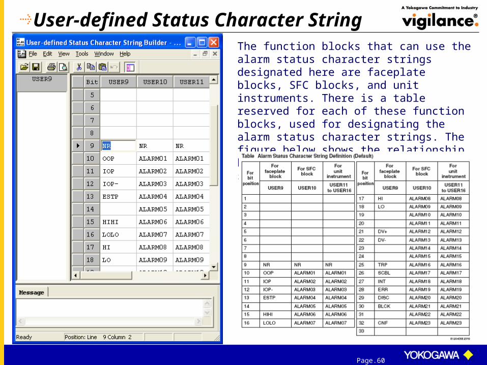
User-defined Status Character String
The function blocks that can use the alarm status character strings designated here are faceplate blocks, SFC blocks, and unit instruments. There is a table reserved for each of these function blocks, used for designating the alarm status character strings. The figure below shows the relationship between the alarm status character string and the bit position(default) for each function block: