cj2h-cpu6 -eip cj2h-cpu6 cj2m-cpu cj2 cpu unit hardware · pdf filesysmac cj series...
TRANSCRIPT

USER’S MANUAL
Cat. No. W472-E1-06
SYSMAC CJ SeriesCJ2H-CPU6@-EIPCJ2H-CPU6@CJ2M-CPU@@
CJ2 CPU Unit Hardware


© OMRON, 2008All rights reserved. No part of this publication may be reproduced, stored in a retrieval system, or transmitted, in any form, orby any means, mechanical, electronic, photocopying, recording, or otherwise, without the prior written permission ofOMRON.
No patent liability is assumed with respect to the use of the information contained herein. Moreover, because OMRON is con-stantly striving to improve its high-quality products, the information contained in this manual is subject to change withoutnotice. Every precaution has been taken in the preparation of this manual. Nevertheless, OMRON assumes no responsibilityfor errors or omissions. Neither is any liability assumed for damages resulting from the use of the information contained inthis publication.


SYSMAC CJ SeriesCJ2H-CPU6@-EIPCJ2H-CPU6@CJ2M-CPU@@CJ2 CPU Unit HardwareUser’s ManualRevised February 2010


1CJ2 CPU Unit Hardware User’s Manual
Introduction
Thank you for purchasing a CJ-series CJ2H-CPU6@(-EIP) or CJ2M-CPU@@ Programmable Controller.This manual contains information required to use the CJ2H-CPU6@(-EIP) and CJ2M-CPU@@. Pleasethoroughly read and understand this manual before you use the CJ2H-CPU6@(-EIP).
This manual is intended for the following personnel, who must also have knowledge of electrical sys-tems (an electrical engineer or the equivalent).• Personnel in charge of installing FA systems• Personnel in charge of designing FA systems.• Personnel in charge of managing FA systems and facilities.
CJ-series CJ2 CPU Units • CJ2H-CPU6@-EIP• CJ2H-CPU6@• CJ2M-CPU3@• CJ2M-CPU1@
In this manual, the following notation is used to indicate the CPU Units. • CJ2H-CPU6@(-EIP): Indicates the CJ2H-CPU6@-EIP and CJ2H-CPU6@ CPU Units. • CJ2M-CPU@@: Indicates the CJ2M-CPU3@ and CJ2M-CPU1@ CPU Units.
Intended Audience
Applicable Products
CJ2 Series
CJ1H-CPU@@H-RCJ1H-CPU@@HCJ1G-CPU@@HCJ1G -CPU@@P(Loop CPU Units)
CJ1-H CPU Units
CJ1 CPU Units
CJ1G-CPU@@
CJ1M CPU Units
CJ1M-CPU@@
CJ-series Power Supply Units
CJ-series Basic I/O Units
CJ-series CPU Bus Units
CJ-series Special I/O Units
CS1H-CPU@@HCS1G-CPU@@H
CS1-H CPU Units
CS-series Power Supply Units
CS-series Basic I/O Units
CS-series CPU Bus Units
CS-series Special I/O Units
CS Series
CS1 CPU Units
CS1H-CPU@@(-V)CS1G-CPU@@(-V)
CS1D CPU Units
CS1D CPU Units for Duplex Systems
CS1D-CPU@@H
CS1D-CPU@@S
CS1D-CPU@@P
NSJ5-TQ@@(B)-G5DNSJ5-SQ@@(B)-G5DNSJ8-TV@@(B)-G5DNSJ10-TV@@(B)-G5DNSJ12-TS@@(B)-G5D
NSJ Controllers
NSJ-series Expansion Units
NSJ Series
NSJ5-TQ@@(B)-M3DNSJ5-SQ@@(B)-M3DNSJ8-TV@@(B)-M3D
NSJ Controllers
CJ2H-CPU6@-EIPCJ2H-CPU6@
CS1D CPU Units for Simplex Systems
CS1D Process-control CPU Units
Note: A special Power Supply Unit must be used for CS1D CPU Units.
CJ2 CPU Units
CJ2H CPU Units
CJ2M CPU Units
CJ2M-CPU3@CJ2M-CPU1@
2 CJ2 CPU Unit Hardware User’s Manual
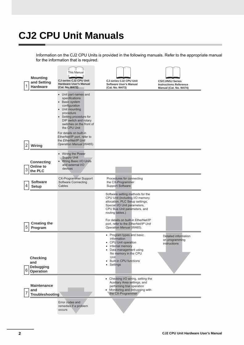
CJ2 CPU Unit Manuals
Information on the CJ2 CPU Units is provided in the following manuals. Refer to the appropriate manualfor the information that is required.
Wiring
1
2
3
4
5
6
7
This Manual
Mountingand Setting Hardware
ConnectingOnline to the PLC
SoftwareSetup
Creating the Program
Checking andDebugging Operation
MaintenanceandTroubleshooting
Error codes and remedies if a problem occurs
CJ-series CJ2 CPU Unit Hardware User’s Manual (Cat. No. W472)
CJ-series CJ2 CPU Unit Software User’s Manual (Cat. No. W473)
• Unit part names and specifications
• Basic system configuration
• Unit mounting procedure
• Setting procedure for DIP switch and rotary switches on the front of the CPU Unit
For details on built-in EtherNet/IP port, refer to the EtherNet/IP Unit Operation Manual (W465)
• Wiring the Power Supply Unit
• Wring Basic I/O Units and external I/O devices
CX-Programmer Support Software Connecting Cables
Procedures for connecting the CX-Programmer Support Software
Software setting methods for the CPU Unit (including I/O memory allocation, PLC Setup settings, Special I/O Unit parameters, CPU Bus Unit parameters, and routing tables.)
For details on built-in EtherNet/IP port, refer to the EtherNet/IP Unit Operation Manual (W465).
• Program types and basic information
• CPU Unit operation • Internal memory • Data management using
file memory in the CPU Unit
• Built-in CPU functions • Settings
• Checking I/O wiring, setting the Auxiliary Area settings, and performing trial operation
• Monitoring and debugging with the CX-Programmer
Detailed information on programming instructions
CS/CJ/NSJ Series Instructions Reference Manual (Cat. No. W474)

3CJ2 CPU Unit Hardware User’s Manual
The CJ2 CPU manuals are organized in the sections listed in the following tables. Refer to the appropri-ate section in the manuals as required.
Manual Configuration
Hardware User’s Manual (Cat. No. W472) (This Manual)Section Content
Section 1 OverviewThis section gives an overview of the CJ2 CPU Units and describes the features and specifications.
Section 2 Basic System Configu-ration and Devices
This section describes the system configuration for the CJ2 CPU Unit.
Section 3 Nomenclature and Functions
This section describes the part names and functions of the CPU Unit and Configuration Units.
Section 4 Support SoftwareThis section describes the types of Support Software to use to perform programming and debugging and how to connect the PLC to the Support Software.
Section 5 InstallationThis section describes the installation locations and how to wire CPU Units and Configu-ration Units.
Section 6 TroubleshootingThis section describes how to check the status for errors that occur during system opera-tion and the remedies for those errors.
Section 7 Inspection and Mainte-nance
This section describes periodic inspection, the service life of the Battery and Power Sup-ply Unit, and how to replace the Battery.
Section 8 Backup Operations This section describes the procedure to back up PLC data.
Appendices
The appendices provide Unit dimensions, details on fatal and non-fatal errors, informa-tion on connecting to serial ports on the CPU Unit, the procedure for installing the USB driver on a computer, and information on load short-circuit protection and line disconnec-tion detection.
Software User’s Manual (Cat. No. W473)Section Content
Section 1 OverviewThis section gives an overview of the CJ2 CPU Units and describes the features and specifications.
Section 2 Internal Memory in the CPU Unit
This section describes the types of memory in the CPU Unit and the data that is stored.
Section 3 CPU Unit Operation This section describes the internal operation of the CPU Unit. Section 4 CPU Unit Initialization This section describes the initial setup of the CPU Unit.Section 5 Understanding Pro-gramming
This section describes program types and programming details, such as symbols and programming instructions.
Section 6 I/O Memory Areas This section describes the I/O memory areas in the CPU Unit.
Section 7 File OperationsThis section describes the files that can be stored in the CPU Unit, the storage destina-tion for those files, and file operations.
Section 8 I/O Allocations and Unit Settings
This section describes the I/O allocations used to exchange data between the CPU Unit and other Units.
Section 9 PLC SetupThis section describes details on the PLC Setup settings, which are used to perform basic settings for the CPU Unit.
Section 10 CPU Unit Functions This section describes functions that are built into the CPU Unit. Section 11 Programming Devices and Communications
This section describes the procedure for connecting the CJ2 CPU Unit to the CX-Pro-grammer or other Support Software and to other devices.
Section 12 CPU Unit Cycle Time This section describes how to monitor and calculate the cycle time.
Appendices
The appendices provide information on programming instructions, execution times, num-ber of steps, Auxiliary Area words and bits, a memory map of the continuous PLC mem-ory addresses, I/O memory operation when power is interrupted, and a comparison of CJ-series and CS-series PLCs.
4 CJ2 CPU Unit Hardware User’s Manual
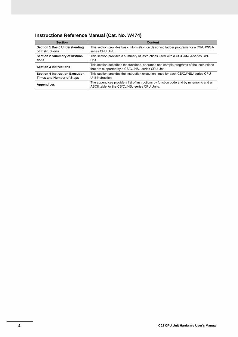
Instructions Reference Manual (Cat. No. W474)Section Content
Section 1 Basic Understanding of Instructions
This section provides basic information on designing ladder programs for a CS/CJ/NSJ-series CPU Unit.
Section 2 Summary of Instruc-tions
This section provides a summary of instructions used with a CS/CJ/NSJ-series CPU Unit.
Section 3 InstructionsThis section describes the functions, operands and sample programs of the instructions that are supported by a CS/CJ/NSJ-series CPU Unit.
Section 4 Instruction Execution Times and Number of Steps
This section provides the instruction execution times for each CS/CJ/NSJ-series CPU Unit instruction.
AppendicesThe appendices provide a list of instructions by function code and by mnemonic and an ASCII table for the CS/CJ/NSJ-series CPU Units.
5CJ2 CPU Unit Hardware User’s Manual
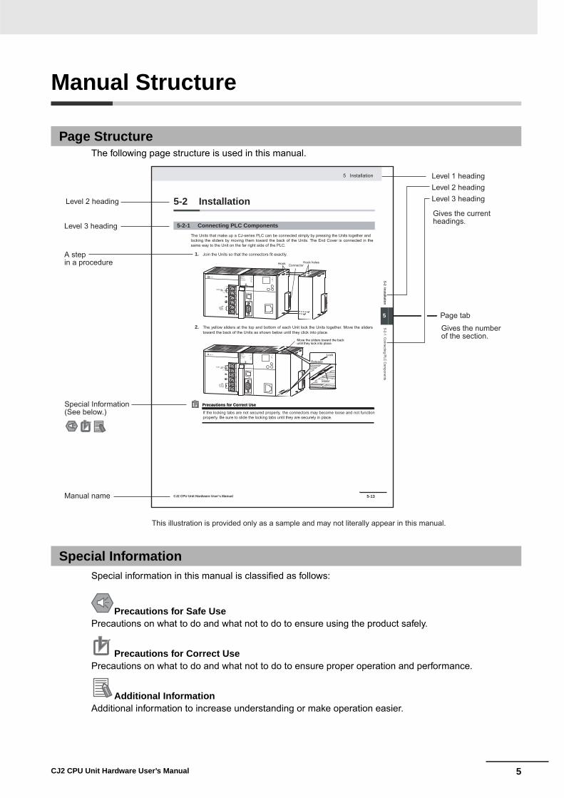
Manual Structure
The following page structure is used in this manual.
Special information in this manual is classified as follows:
Page Structure
Special Information
Precautions for Safe UsePrecautions on what to do and what not to do to ensure using the product safely.
Precautions for Correct UsePrecautions on what to do and what not to do to ensure proper operation and performance.
Additional InformationAdditional information to increase understanding or make operation easier.
Level 1 headingLevel 2 headingLevel 3 headingLevel 2 heading
A stepin a procedure
Manual name
Level 3 heading
Page tab
Gives the current headings.
Gives the number of the section.
This illustration is provided only as a sample and may not literally appear in this manual.
Special Information(See below.)
5-13
5 Installation
CJ2 CPU Unit Hardware User’s Manual
noi
tall
ats
nI 2
-5
5
stne
n op
moC
CLP
gnit
cenn
oC
1-2-
5
5-2 Installation
The Units that make up a CJ-series PLC can be connected simply by pressing the Units together andlocking the sliders by moving them toward the back of the Units. The End Cover is connected in thesame way to the Unit on the far right side of the PLC.
1. Join the Units so that the connectors fit exactly.
2. The yellow sliders at the top and bottom of each Unit lock the Units together. Move the sliderstoward the back of the Units as shown below until they click into place.
Precautions for Correct UsePrecautions for Correct Use
If the locking tabs are not secured properly, the connectors may become loose and not functionproperly. Be sure to slide the locking tabs until they are securely in place.
5-2-1 Connecting PLC Components
ConnectorHook Hook holes
Slider
Lock
Release
Move the sliders toward the back until they lock into place.

6 CJ2 CPU Unit Hardware User’s Manual

7CJ2 CPU Unit Hardware User’s Manual
Sections in this Manual
1
2
3
4
5
6
7
8
A
1
2
3
4
5
6
7
8
A
Overview
Basic System Configuration and Devices
Nomenclature and Functions
Support Software
Installation
Troubleshooting
Inspection and Maintenance
Backup Operations
Appendices

8 CJ2 CPU Unit Hardware User’s Manual

9CJ2 CPU Unit Hardware User’s Manual
CONTENTS
Introduction............................................................................................................... 1
CJ2 CPU Unit Manuals ............................................................................................. 2
Manual Structure ...................................................................................................... 5
Sections in this Manual............................................................................................ 7
Safety Precautions ................................................................................................. 17
Application Precautions......................................................................................... 21
Operating Environment Precautions .................................................................... 26
Regulations and Standards ................................................................................... 27
Unit Versions of CJ2 CPU Units ............................................................................ 29
Related Manuals ..................................................................................................... 34
Section 1 Overview
1-1 Overview of CJ2 CPU Units .................................................................................................... 1-21-1-1 Overview..................................................................................................................................... 1-21-1-2 CJ2 CPU Unit Features .............................................................................................................. 1-4
1-2 Basic Operating Procedure .................................................................................................. 1-111-3 Specifications ........................................................................................................................ 1-12
1-3-1 General Specifications.............................................................................................................. 1-121-3-2 Performance Specifications ...................................................................................................... 1-131-3-3 Function Specifications............................................................................................................. 1-19
Section 2 Basic System Configuration and Devices
2-1 Basic System Configuration................................................................................................... 2-22-1-1 Basic System Configuration........................................................................................................ 2-22-1-2 CPU Rack ................................................................................................................................... 2-32-1-3 Expansion Racks ...................................................................................................................... 2-102-1-4 Configuration Units ................................................................................................................... 2-132-1-5 Calculating Unit Current Consumption ..................................................................................... 2-212-1-6 Calculating Power Consumption............................................................................................... 2-24
2-2 Expanded System Configuration ......................................................................................... 2-262-2-1 Serial Communications............................................................................................................. 2-262-2-2 Communications Networks ....................................................................................................... 2-28

10 CJ2 CPU Unit Hardware User’s Manual
Section 3 Nomenclature and Functions
3-1 CPU Units ................................................................................................................................. 3-23-1-1 CPU Section................................................................................................................................ 3-23-1-2 Built-in EtherNet/IP Section (CJ2H-CPU6@-EIP and CJ2M-CPU3@ Only) ............................... 3-8
3-2 Memory Card.......................................................................................................................... 3-133-2-1 Models and Specifications ........................................................................................................ 3-133-2-2 Operating Procedures ............................................................................................................... 3-133-2-3 Installing and Removing............................................................................................................ 3-14
3-3 Serial Option Boards (CJ2M-CPU3@ Only) ......................................................................... 3-173-3-1 Overview ................................................................................................................................... 3-17
3-4 Power Supply Units ............................................................................................................... 3-183-4-1 Models and Specifications ........................................................................................................ 3-183-4-2 Components.............................................................................................................................. 3-213-4-3 Selecting a Power Supply Unit .................................................................................................. 3-24
3-5 CJ-series Basic I/O Units ...................................................................................................... 3-253-5-1 Basic I/O Units with Terminal Blocks......................................................................................... 3-253-5-2 Thirty-two/Sixty-four-point Basic I/O Units with Connectors...................................................... 3-27
3-6 I/O Control Units and I/O Interface Units ............................................................................. 3-293-6-1 Component Names ................................................................................................................... 3-293-6-2 System Configuration................................................................................................................ 3-29
Section 4 Support Software
4-1 Support Software..................................................................................................................... 4-24-1-1 CX-One FA Integrated Tool Package .......................................................................................... 4-2
4-2 Connection Methods ............................................................................................................... 4-54-2-1 Connecting by USB..................................................................................................................... 4-54-2-2 Connecting by RS-232C ............................................................................................................. 4-74-2-3 Connecting to Ethernet (CJ2H-CPU6@-EIP and CJ2M-CPU3@ Only) ...................................... 4-9
Section 5 Installation
5-1 Fail-safe Circuits...................................................................................................................... 5-25-2 Installation................................................................................................................................ 5-4
5-2-1 Installation and Wiring Precautions............................................................................................. 5-45-2-2 Installation in a Control Panel ..................................................................................................... 5-65-2-3 Assembled Appearance and Dimensions ................................................................................... 5-85-2-4 Connecting PLC Components................................................................................................... 5-135-2-5 DIN Track Installation ................................................................................................................ 5-155-2-6 Connecting CJ-series Expansion Racks ................................................................................... 5-17
5-3 Wiring ..................................................................................................................................... 5-205-3-1 Power Supply Wiring ................................................................................................................. 5-205-3-2 Wiring CJ-series Basic I/O Units with Terminal Blocks ............................................................. 5-275-3-3 Wiring Basic I/O Units with Connectors .................................................................................... 5-295-3-4 Connecting to Connector-Terminal Block Conversion Units or I/O Relay Terminals ................. 5-335-3-5 Connecting I/O Devices ............................................................................................................ 5-345-3-6 Connecting through an Ethernet Cable (CJ2H-CPU6@-EIP and CJ2M-CPU3@ Only)............ 5-38
5-4 Control Panel Installation ..................................................................................................... 5-415-4-1 Temperature .............................................................................................................................. 5-415-4-2 Humidity .................................................................................................................................... 5-435-4-3 Vibration and Shock .................................................................................................................. 5-435-4-4 Atmosphere............................................................................................................................... 5-435-4-5 Electrical Environment .............................................................................................................. 5-445-4-6 Grounding ................................................................................................................................. 5-49
11CJ2 CPU Unit Hardware User’s Manual
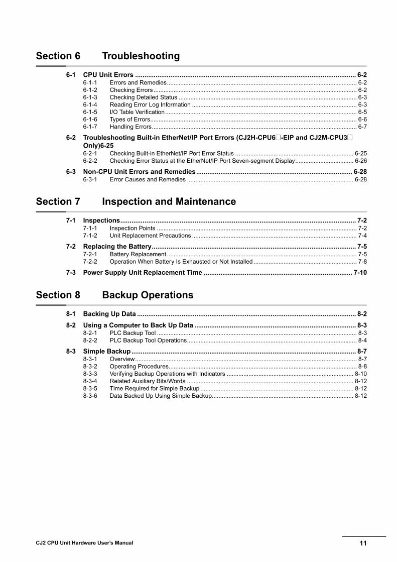
Section 6 Troubleshooting
6-1 CPU Unit Errors ....................................................................................................................... 6-26-1-1 Errors and Remedies.................................................................................................................. 6-26-1-2 Checking Errors .......................................................................................................................... 6-26-1-3 Checking Detailed Status ........................................................................................................... 6-36-1-4 Reading Error Log Information ................................................................................................... 6-36-1-5 I/O Table Verification................................................................................................................... 6-56-1-6 Types of Errors............................................................................................................................ 6-66-1-7 Handling Errors........................................................................................................................... 6-7
6-2 Troubleshooting Built-in EtherNet/IP Port Errors (CJ2H-CPU6@-EIP and CJ2M-CPU3@ Only)6-256-2-1 Checking Built-in EtherNet/IP Port Error Status ....................................................................... 6-256-2-2 Checking Error Status at the EtherNet/IP Port Seven-segment Display................................... 6-26
6-3 Non-CPU Unit Errors and Remedies.................................................................................... 6-286-3-1 Error Causes and Remedies .................................................................................................... 6-28
Section 7 Inspection and Maintenance
7-1 Inspections............................................................................................................................... 7-27-1-1 Inspection Points ........................................................................................................................ 7-27-1-2 Unit Replacement Precautions ................................................................................................... 7-4
7-2 Replacing the Battery.............................................................................................................. 7-57-2-1 Battery Replacement .................................................................................................................. 7-57-2-2 Operation When Battery Is Exhausted or Not Installed .............................................................. 7-8
7-3 Power Supply Unit Replacement Time ................................................................................ 7-10
Section 8 Backup Operations
8-1 Backing Up Data ...................................................................................................................... 8-28-2 Using a Computer to Back Up Data ....................................................................................... 8-3
8-2-1 PLC Backup Tool ........................................................................................................................ 8-38-2-2 PLC Backup Tool Operations...................................................................................................... 8-4
8-3 Simple Backup......................................................................................................................... 8-78-3-1 Overview..................................................................................................................................... 8-78-3-2 Operating Procedures................................................................................................................. 8-88-3-3 Verifying Backup Operations with Indicators ............................................................................ 8-108-3-4 Related Auxiliary Bits/Words .................................................................................................... 8-128-3-5 Time Required for Simple Backup ............................................................................................ 8-128-3-6 Data Backed Up Using Simple Backup..................................................................................... 8-12
12 CJ2 CPU Unit Hardware User’s Manual
Appendices
A-1 Specifications of Basic I/O Units ...........................................................................................A-2A-1-1 Overview of Units ........................................................................................................................A-2A-1-2 Basic I/O Units ............................................................................................................................A-5A-1-3 Precautions on Contact Output Units........................................................................................A-57A-1-4 Connecting Connector-Terminal Block Conversion Units and I/O Relay Terminals ..................A-59
A-2 Dimensions ............................................................................................................................A-94A-2-1 CJ2H CPU Units .......................................................................................................................A-94A-2-2 CJ2M CPU Units .......................................................................................................................A-95A-2-3 Power Supply Units ...................................................................................................................A-96A-2-4 Basic I/O Units ..........................................................................................................................A-98A-2-5 I/O Control Unit and I/O Interface Unit ....................................................................................A-101A-2-6 I/O Memory Card ....................................................................................................................A-101A-2-7 Serial Option Boards (CJ2M-CPU3@ Only)............................................................................A-101
A-3 Fatal and Non-fatal Error Details........................................................................................A-103A-3-1 Fatal Errors .............................................................................................................................A-103A-3-2 Non-fatal Errors.......................................................................................................................A-108
A-4 Connecting to a Serial Port on the CPU Unit ....................................................................A-111A-4-1 Serial Port Interface Types and Specifications........................................................................A-111A-4-2 Connection Examples .............................................................................................................A-117A-4-3 Applicable Connectors and Recommended Cables................................................................A-133
A-5 Installing the USB Driver ....................................................................................................A-140A-6 Load Short-circuit Protection and Line Disconnection Detection for Basic I/O Units ..A-150
A-6-1 Load Short-circuit Protection and Line Disconnection Detection for CJ1W-OD202................A-150A-6-2 Load Short-circuit Protection for CJ1W-OD204/OD212/OD232/MD232.................................A-152
A-7 Relay Output Noise Reduction Methods ...........................................................................A-154A-8 Functions Supported for Unit Versions.............................................................................A-156
Index................................................................................................................ Index-1
Revision History........................................................................................Revision-1

13CJ2 CPU Unit Hardware User’s Manual
Read and Understand this ManualPlease read and understand this manual before using the product. Please consult your OMRON representative if you have any questions or comments.
Warranty and Limitations of Liability WARRANTY
OMRON's exclusive warranty is that the products are free from defects in materials and workmanship for a period of one year (or other period if specified) from date of sale by OMRON.
OMRON MAKES NO WARRANTY OR REPRESENTATION, EXPRESS OR IMPLIED, REGARDING NON-INFRINGEMENT, MERCHANTABILITY, OR FITNESS FOR PARTICULAR PURPOSE OF THE PRODUCTS. ANY BUYER OR USER ACKNOWLEDGES THAT THE BUYER OR USER ALONE HAS DETERMINED THAT THE PRODUCTS WILL SUITABLY MEET THE REQUIREMENTS OF THEIR INTENDED USE. OMRON DISCLAIMS ALL OTHER WARRANTIES, EXPRESS OR IMPLIED.
LIMITATIONS OF LIABILITYOMRON SHALL NOT BE RESPONSIBLE FOR SPECIAL, INDIRECT, OR CONSEQUENTIAL DAMAGES, LOSS OF PROFITS OR COMMERCIAL LOSS IN ANY WAY CONNECTED WITH THE PRODUCTS, WHETHER SUCH CLAIM IS BASED ON CONTRACT, WARRANTY, NEGLIGENCE, OR STRICT LIABILITY.
In no event shall the responsibility of OMRON for any act exceed the individual price of the product on which liability is asserted.
IN NO EVENT SHALL OMRON BE RESPONSIBLE FOR WARRANTY, REPAIR, OR OTHER CLAIMS REGARDING THE PRODUCTS UNLESS OMRON'S ANALYSIS CONFIRMS THAT THE PRODUCTS WERE PROPERLY HANDLED, STORED, INSTALLED, AND MAINTAINED AND NOT SUBJECT TO CONTAMINATION, ABUSE, MISUSE, OR INAPPROPRIATE MODIFICATION OR REPAIR.

14 CJ2 CPU Unit Hardware User’s Manual
Application ConsiderationsSUITABILITY FOR USE
OMRON shall not be responsible for conformity with any standards, codes, or regulations that apply to the combination of products in the customer's application or use of the products.
At the customer's request, OMRON will provide applicable third party certification documents identifying ratings and limitations of use that apply to the products. This information by itself is not sufficient for a complete determination of the suitability of the products in combination with the end product, machine, system, or other application or use.
The following are some examples of applications for which particular attention must be given. This is not intended to be an exhaustive list of all possible uses of the products, nor is it intended to imply that the uses listed may be suitable for the products:
• Outdoor use, uses involving potential chemical contamination or electrical interference, or conditions or uses not described in this manual.
• Nuclear energy control systems, combustion systems, railroad systems, aviation systems, medical equipment, amusement machines, vehicles, safety equipment, and installations subject to separate industry or government regulations.
• Systems, machines, and equipment that could present a risk to life or property.
Please know and observe all prohibitions of use applicable to the products.
NEVER USE THE PRODUCTS FOR AN APPLICATION INVOLVING SERIOUS RISK TO LIFE OR PROPERTY WITHOUT ENSURING THAT THE SYSTEM AS A WHOLE HAS BEEN DESIGNED TO ADDRESS THE RISKS, AND THAT THE OMRON PRODUCTS ARE PROPERLY RATED AND INSTALLED FOR THE INTENDED USE WITHIN THE OVERALL EQUIPMENT OR SYSTEM.
PROGRAMMABLE PRODUCTS OMRON shall not be responsible for the user's programming of a programmable product, or any consequence thereof.

15CJ2 CPU Unit Hardware User’s Manual
DisclaimersCHANGE IN SPECIFICATIONS
Product specifications and accessories may be changed at any time based on improvements and other reasons.
It is our practice to change model numbers when published ratings or features are changed, or when significant construction changes are made. However, some specifications of the products may be changed without any notice. When in doubt, special model numbers may be assigned to fix or establish key specifications for your application on your request. Please consult with your OMRON representative at any time to confirm actual specifications of purchased products.
DIMENSIONS AND WEIGHTS Dimensions and weights are nominal and are not to be used for manufacturing purposes, even when tolerances are shown.
PERFORMANCE DATA Performance data given in this manual is provided as a guide for the user in determining suitability and does not constitute a warranty. It may represent the result of OMRON's test conditions, and the users must correlate it to actual application requirements. Actual performance is subject to the OMRON Warranty and Limitations of Liability.
ERRORS AND OMISSIONS The information in this manual has been carefully checked and is believed to be accurate; however, no responsibility is assumed for clerical, typographical, or proofreading errors, or omissions.

16 CJ2 CPU Unit Hardware User’s Manual

17CJ2 CPU Unit Hardware User’s Manual
Safety Precautions
The following notation is used in this manual to provide precautions required to ensure safe usage of aCJ-series PLC. The safety precautions that are provided are extremely important to safety. Always readand heed the information provided in all safety precautions.
Definition of Precautionary Information
WARNINGIndicates a potentially hazardous situation which, if not avoided, could result in death or serious injury. Additionally, there may be severe property damage.
CautionIndicates a potentially hazardous situation which, if not avoided, may result in minor or moderate injury, or property damage.
Precautions for Safe UseIndicates precautions on what to do and what not to do to ensure using the product safely.
Precautions for Correct UseIndicates precautions on what to do and what not to do to ensure proper operation and performance.

18 CJ2 CPU Unit Hardware User’s Manual
Symbols
The triangle symbol indicates precautions (including warnings). The specific operation is shown in the triangle and explained in text. This example indicates a precaution for electric shock.
The circle and slash symbol indicates operations that you must not do. The specific operation is shown in the circle and explained in text.
The filled circle symbol indicates operations that you must do. The specific operation is shown in the circle and explained in text. This example shows a general precaution for something that you must do.
The triangle symbol indicates precautions (including warnings). The specific operation is shown in the triangle and explained in text. This example indicates a general precaution.
The triangle symbol indicates precautions (including warnings). The specific operation is shown in the triangle and explained in text. This example indicates a precaution for hot surfaces.
19CJ2 CPU Unit Hardware User’s Manual
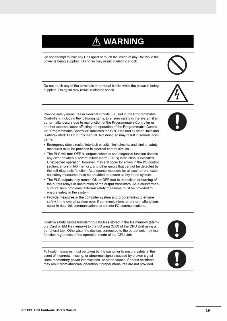
WARNING
Do not attempt to take any Unit apart or touch the inside of any Unit while the power is being supplied. Doing so may result in electric shock.
Do not touch any of the terminals or terminal blocks while the power is being supplied. Doing so may result in electric shock.
Provide safety measures in external circuits (i.e., not in the Programmable Controller), including the following items, to ensure safety in the system if an abnormality occurs due to malfunction of the Programmable Controller or another external factor affecting the operation of the Programmable Control-ler. "Programmable Controller" indicates the CPU Unit and all other Units and is abbreviated "PLC" in this manual. Not doing so may result in serious acci-dents.• Emergency stop circuits, interlock circuits, limit circuits, and similar safety
measures must be provided in external control circuits.• The PLC will turn OFF all outputs when its self-diagnosis function detects
any error or when a severe failure alarm (FALS) instruction is executed. Unexpected operation, however, may still occur for errors in the I/O control section, errors in I/O memory, and other errors that cannot be detected by the self-diagnosis function. As a countermeasure for all such errors, exter-nal safety measures must be provided to ensure safety in the system.
• The PLC outputs may remain ON or OFF due to deposition or burning of the output relays or destruction of the output transistors. As a countermea-sure for such problems, external safety measures must be provided to ensure safety in the system.
• Provide measures in the computer system and programming to ensure safety in the overall system even if communications errors or malfunctions occur in data link communications or remote I/O communications.
Confirm safety before transferring data files stored in the file memory (Mem-ory Card or EM file memory) to the I/O area (CIO) of the CPU Unit using a peripheral tool. Otherwise, the devices connected to the output unit may mal-function regardless of the operation mode of the CPU Unit.
Fail-safe measures must be taken by the customer to ensure safety in the event of incorrect, missing, or abnormal signals caused by broken signal lines, momentary power interruptions, or other causes. Serious accidents may result from abnormal operation if proper measures are not provided.

20 CJ2 CPU Unit Hardware User’s Manual
Caution
Execute online edit only after confirming that no adverse effects will be caused by extending the cycle time. Otherwise, the input signals may not be readable.
Confirm safety at the destination node before transferring a program, PLC Setup, I/O tables, I/O memory contents, or parameters to another node or changing contents of the any of these items. Transferring or changing data can result in unexpected system operation.
The CJ2 CPU Units automatically back up the user program and parameter data to flash memory when these are written to the CPU Unit. I/O memory including the DM, EM, and Holding Areas), however, is not written to flash memory.The DM, EM, and Holding Areas can be held during power interruptions with a battery. If there is a battery error, the contents of these areas may not be accurate after a power interruption. If the contents of the DM, EM, and Hold-ing Areas are used to control external outputs, prevent inappropriate outputs from being made whenever the Battery Error Flag (A402.04) is ON.
Tighten the terminal screws on the AC Power Supply Unit to the torque spec-ified in the operation manual. The loose screws may result in burning or mal-function.
Do not touch the Power Supply Unit when power is being supplied or immedi-ately after the power supply is turned OFF. The Power Supply Unit will be hot and you may be burned.
When connecting a personal computer or other peripheral device to a PLC to which a non-insulated Power Supply Unit (CJ1W-PD022) is mounted, either ground the 0 V side of the external power supply or do not ground the exter-nal power supply at all ground. A short-circuit will occur in the external power supply if incorrect grounding methods are used. Never ground the 24 V side, as shown below.
24 V
0 V
FG CPU Unit
0 V
Wiring in Which the 24-V Power Supply Will ShortNon-insulatedDC power supply
Power Supply Unit
Peripheral cable
Peripheral device (e.g., personal computer)
21CJ2 CPU Unit Hardware User’s Manual
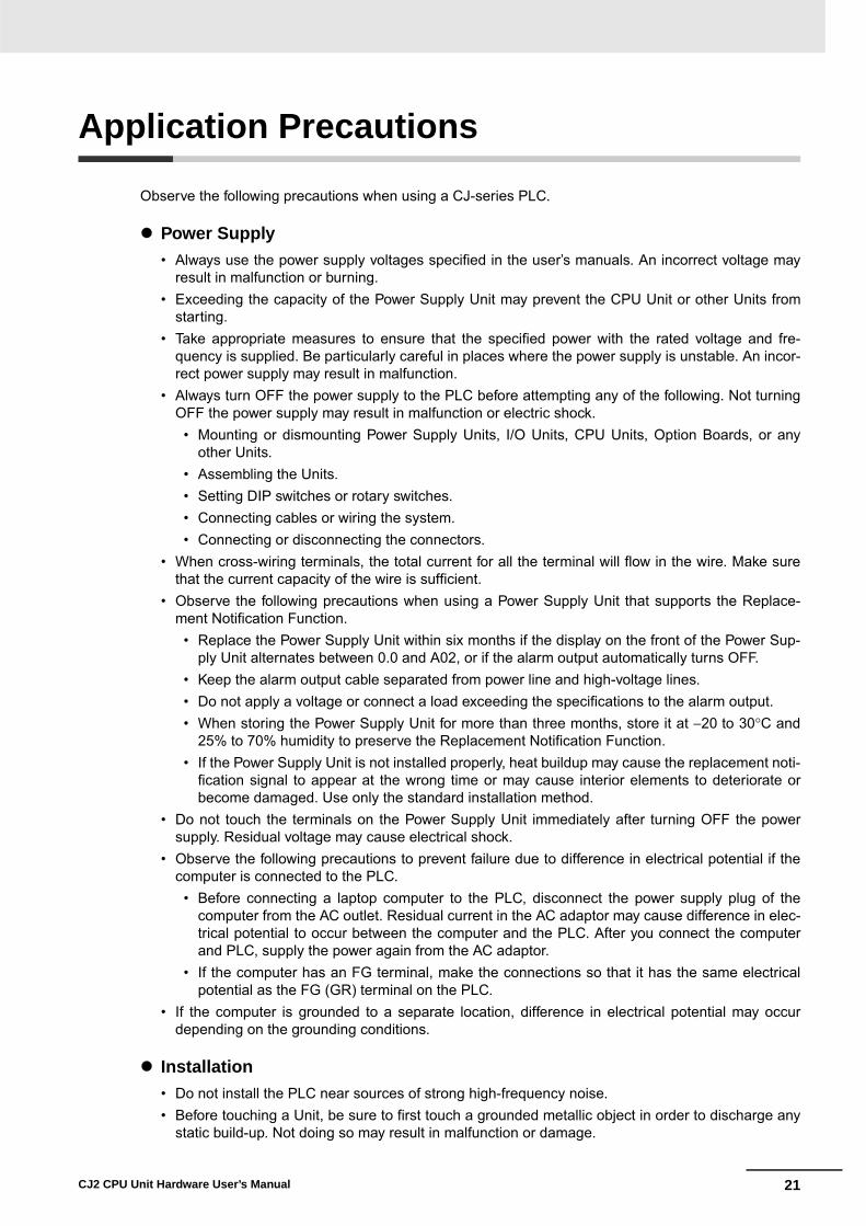
Application Precautions
Observe the following precautions when using a CJ-series PLC.
� Power Supply• Always use the power supply voltages specified in the user’s manuals. An incorrect voltage may
result in malfunction or burning.• Exceeding the capacity of the Power Supply Unit may prevent the CPU Unit or other Units from
starting. • Take appropriate measures to ensure that the specified power with the rated voltage and fre-
quency is supplied. Be particularly careful in places where the power supply is unstable. An incor-rect power supply may result in malfunction.
• Always turn OFF the power supply to the PLC before attempting any of the following. Not turningOFF the power supply may result in malfunction or electric shock.
• Mounting or dismounting Power Supply Units, I/O Units, CPU Units, Option Boards, or anyother Units.
• Assembling the Units.• Setting DIP switches or rotary switches.• Connecting cables or wiring the system.• Connecting or disconnecting the connectors.
• When cross-wiring terminals, the total current for all the terminal will flow in the wire. Make surethat the current capacity of the wire is sufficient.
• Observe the following precautions when using a Power Supply Unit that supports the Replace-ment Notification Function.
• Replace the Power Supply Unit within six months if the display on the front of the Power Sup-ply Unit alternates between 0.0 and A02, or if the alarm output automatically turns OFF.
• Keep the alarm output cable separated from power line and high-voltage lines.• Do not apply a voltage or connect a load exceeding the specifications to the alarm output.• When storing the Power Supply Unit for more than three months, store it at −20 to 30°C and
25% to 70% humidity to preserve the Replacement Notification Function.• If the Power Supply Unit is not installed properly, heat buildup may cause the replacement noti-
fication signal to appear at the wrong time or may cause interior elements to deteriorate orbecome damaged. Use only the standard installation method.
• Do not touch the terminals on the Power Supply Unit immediately after turning OFF the powersupply. Residual voltage may cause electrical shock.
• Observe the following precautions to prevent failure due to difference in electrical potential if thecomputer is connected to the PLC.
• Before connecting a laptop computer to the PLC, disconnect the power supply plug of thecomputer from the AC outlet. Residual current in the AC adaptor may cause difference in elec-trical potential to occur between the computer and the PLC. After you connect the computerand PLC, supply the power again from the AC adaptor.
• If the computer has an FG terminal, make the connections so that it has the same electricalpotential as the FG (GR) terminal on the PLC.
• If the computer is grounded to a separate location, difference in electrical potential may occurdepending on the grounding conditions.
� Installation• Do not install the PLC near sources of strong high-frequency noise.• Before touching a Unit, be sure to first touch a grounded metallic object in order to discharge any
static build-up. Not doing so may result in malfunction or damage.
22 CJ2 CPU Unit Hardware User’s Manual
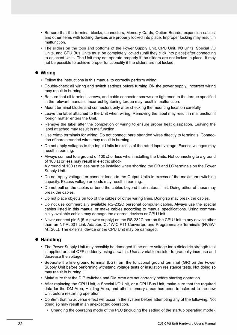
• Be sure that the terminal blocks, connectors, Memory Cards, Option Boards, expansion cables,and other items with locking devices are properly locked into place. Improper locking may result inmalfunction.
• The sliders on the tops and bottoms of the Power Supply Unit, CPU Unit, I/O Units, Special I/OUnits, and CPU Bus Units must be completely locked (until they click into place) after connectingto adjacent Units. The Unit may not operate properly if the sliders are not locked in place. It maynot be possible to achieve proper functionality if the sliders are not locked.
� Wiring• Follow the instructions in this manual to correctly perform wiring.• Double-check all wiring and switch settings before turning ON the power supply. Incorrect wiring
may result in burning.• Be sure that all terminal screws, and cable connector screws are tightened to the torque specified
in the relevant manuals. Incorrect tightening torque may result in malfunction.• Mount terminal blocks and connectors only after checking the mounting location carefully.• Leave the label attached to the Unit when wiring. Removing the label may result in malfunction if
foreign matter enters the Unit.• Remove the label after the completion of wiring to ensure proper heat dissipation. Leaving the
label attached may result in malfunction.• Use crimp terminals for wiring. Do not connect bare stranded wires directly to terminals. Connec-
tion of bare stranded wires may result in burning.• Do not apply voltages to the Input Units in excess of the rated input voltage. Excess voltages may
result in burning.• Always connect to a ground of 100 Ω or less when installing the Units. Not connecting to a ground
of 100 Ω or less may result in electric shock.A ground of 100 Ω or less must be installed when shorting the GR and LG terminals on the PowerSupply Unit.
• Do not apply voltages or connect loads to the Output Units in excess of the maximum switchingcapacity. Excess voltage or loads may result in burning.
• Do not pull on the cables or bend the cables beyond their natural limit. Doing either of these maybreak the cables.
• Do not place objects on top of the cables or other wiring lines. Doing so may break the cables.• Do not use commercially available RS-232C personal computer cables. Always use the special
cables listed in this manual or make cables according to manual specifications. Using commer-cially available cables may damage the external devices or CPU Unit.
• Never connect pin 6 (5-V power supply) on the RS-232C port on the CPU Unit to any device otherthan an NT-AL001 Link Adapter, CJ1W-CIF11 Converter, and Programmable Terminals (NV3W-M@20L). The external device or the CPU Unit may be damaged.
� Handling• The Power Supply Unit may possibly be damaged if the entire voltage for a dielectric strength test
is applied or shut OFF suddenly using a switch. Use a variable resistor to gradually increase anddecrease the voltage.
• Separate the line ground terminal (LG) from the functional ground terminal (GR) on the PowerSupply Unit before performing withstand voltage tests or insulation resistance tests. Not doing somay result in burning.
• Make sure that the DIP switches and DM Area are set correctly before starting operation.• After replacing the CPU Unit, a Special I/O Unit, or a CPU Bus Unit, make sure that the required
data for the DM Area, Holding Area, and other memory areas has been transferred to the newUnit before restarting operation.
• Confirm that no adverse effect will occur in the system before attempting any of the following. Notdoing so may result in an unexpected operation.
• Changing the operating mode of the PLC (including the setting of the startup operating mode).

23CJ2 CPU Unit Hardware User’s Manual
• Force-setting/force-resetting any bit in memory.• Changing the present value of any word or any set value in memory.
• Do not attempt to disassemble, repair, or modify any Units. Any attempt to do so may result in mal-function, fire, or electric shock.
• Do not drop the PLC or subject abnormal vibration or shock to it.• The life of the battery will be reduced if the PLC is left for a period of time without a battery
installed and without power supply, and then a battery is installed without turning ON the powersupply.
• Replace the battery as soon as a battery error occurs or as soon as the specified battery backuptime expires. Be sure to install a replacement battery within two years of the production dateshown on the battery's label.
• Before replacing the battery, turn ON power for at least 5 minutes before starting the replacementprocedure and complete replacing the battery within 5 minutes of turning OFF the power supply.Memory contents may be corrupted if this precaution is not obeyed.
• If the Battery Error Flag is used in programming the application, confirm system safety even if thesystem detects a battery error before you replace the battery while the power is ON.
• Do not short the battery terminals or charge, disassemble, heat, or incinerate the battery. Do notsubject the battery to strong shocks. Doing any of these may result in leakage, rupture, heat gen-eration, or ignition of the battery. Dispose of any battery that has been dropped on the floor or oth-erwise subjected to excessive shock. Batteries that have been subjected to shock may leak if theyare used.
• UL standards require that only an experienced engineer can replace the battery. Make sure thatan experienced engineer is in charge of battery replacement. Follow the procedure for batteryreplacement given in this manual.
• Dispose of the product and batteries according to local ordinances as they apply.
• If the I/O Hold Bit is turned ON, the outputs from the PLC will not be turned OFF and will maintaintheir previous status when the PLC is switched from RUN or MONITOR mode to PROGRAMmode. Make sure that the external loads will not produce dangerous conditions when this occurs.(When operation stops for a fatal error, including those produced with the FALS(007) instruction,all outputs from Output Unit will be turned OFF and only the internal output status will be main-tained.)
• Unexpected operation may result if inappropriate data link tables or parameters are set. Even ifappropriate data link tables and parameters have been set, confirm that the controlled system willnot be adversely affected before starting or stopping data links.
• Write programs so that any data that is received for data link communications is used only if thereare no errors in the CPU Units that are the sources of the data. Use the CPU Unit error informa-tion in the status flags to check for errors in the source CPU Units. If there are errors in sourceCPU Units, they may send incorrect data.
• All CPU Bus Units will be restarted when routing tables are transferred from a ProgrammingDevice to the CPU Unit. Restarting these Units is required to read and enable the new routingtables. Confirm that the system will not be adversely affected before transferring the routingtables.
• Tag data links will stop between related nodes while tag data link parameters are being trans-ferred during PLC operation. Confirm that the system will not be adversely affected before trans-ferring the tag data link parameters.
• If there is interference with network communications, output status will depend on the devices thatare being used. When using devices with outputs, confirm the operation that will occur when thereis interference with communications, and implement safety measures as required.

24 CJ2 CPU Unit Hardware User’s Manual
• When creating an AUTOEXEC.IOM file from a Programming Device (a Programming Console orthe CX-Programmer) to automatically transfer data at startup, set the first write address toD20000 and be sure that the size of data written does not exceed the size of the DM Area. Whenthe data file is read from the Memory Card at startup, data will be written in the CPU Unit startingat D20000 even if another address was set when the AUTOEXEC.IOM file was created. Also, ifthe DM Area is exceeded (which is possible when the CX-Programmer is used), the remainingdata will be written to the EM Area.
• The user program and parameter area data in the CJ2 CPU Units are backed up in the built-inflash memory. The BKUP indicator will light on the front of the CPU Unit when the backup opera-tion is in progress. Do not turn OFF the power supply to the CPU Unit when the BKUP indicator islit. The data will not be backed up if power is turned OFF.
• Check the user program and Unit parameter settings for proper execution before actually runningthem on the Unit. Not checking the program and parameter settings may result in an unexpectedoperation.
• When setting a Special I/O Unit or CPU Bus Unit in the I/O tables, carefully check the safety of thedevices at the connection target before restarting the Unit.
• Do not turn OFF the power supply to the PLC when reading or writing a Memory Card. Also, donot remove the Memory Card when the BUSY indicator is lit. Doing so may make the MemoryCard unusable.To remove a Memory Card, first press the memory card power supply switch and then wait for theBUSY indicator to go out before removing the Memory Card.
• When restoring data, carefully check that the selected data is the correct data to be restoredbefore executing the restore operation. Depending on the contents of the selected data, the con-trol system may operate unexpectedly after the data is restored.
• Some Special I/O Units and CPU Bus Units operate with parameters stored in the CPU Unit (e.g.,words allocated in DM Area, data link tables, or Ethernet settings). Information on restrictions willbe displayed in the Information Area in the PLC Backup Tool if there are any restrictions for theselected CPU Bus Unit or Special I/O Unit. Check the restrictions, and then be sure to select boththe CPU Unit and the CPU Bus Unit or Special I/O Unit when backing up or restoring data. Thecontrol system may operate unexpectedly if the equipment is started with the data backed up orrestored without selecting both Units.
• Information on restrictions will be displayed in the Information Area in the PLC Backup Tool if thedata to be stored includes a Unit that has restrictions on backup. Check the information on restric-tions and take the required countermeasures. The control system may operate unexpectedlywhen the equipment is operated after the data is restored
• Before restoring data during PLC operation, be sure that there will be no problem if PLC operationstops. If the PLC stops at an unexpected time, the control system may operate unexpectedly.
• Be sure to turn the PLC power supply OFF and then back ON after restoring data. If the power isnot reset, the system may not be updated with the restored data, and the control system mayoperate unexpectedly.
• Data on forced status can be backed up but it cannot be restored. Perform the procedure to force-set or force-reset bits from the CX-Programmer as required before starting operation after restor-ing data that includes forced status. Depending on the difference in the forced status, the controlsystem may operate unexpectedly.
• If a symbol or memory address (only symbols are allowed for ST programming) is specified for thesuffix of an array variable in ladder or ST programming, be sure that the specified element numberdoes not exceed the maximum memory area range.Specifying an element number that exceeds the maximum range of the memory area specified forthe symbol will result accessing data in a different memory area, and may result in unexpectedoperation.
• If a symbol or address is specified for an offset in a ladder diagram, program so that the memoryarea of the start address is not exceeded when the offset is specified indirectly using a wordaddress or symbol.If an indirect specification causes the address to exceed the area of the start address, the systemwill access data in other area, and unexpected operation may occur.

25CJ2 CPU Unit Hardware User’s Manual
� External Circuits• Always turn ON power to the PLC before turning ON power to the control system. If the PLC
power supply is turned ON after the control power supply, temporary errors may result in controlsystem signals because the output terminals on DC Output Units and other Units will momentarilyturn ON when power is turned ON to the PLC.
• Install external breakers and take other safety measures against short-circuiting in external wiring.Insufficient safety measures against short-circuiting may result in burning.

26 CJ2 CPU Unit Hardware User’s Manual
Operating Environment Precautions
� Follow the instructions in this manual to correctly perform installation.
� Do not operate the control system in the following locations:• Locations subject to direct sunlight.• Locations subject to temperatures or humidity outside the range specified in the specifications.• Locations subject to condensation as the result of severe changes in temperature.• Locations subject to corrosive or flammable gases.• Locations subject to dust (especially iron dust) or salts.• Locations subject to exposure to water, oil, or chemicals.• Locations subject to shock or vibration.
� Take appropriate and sufficient countermeasures when installing systems in the following locations:• Locations subject to static electricity or other forms of noise.• Locations subject to strong electromagnetic fields.• Locations subject to possible exposure to radioactivity.• Locations close to power supplies.
27CJ2 CPU Unit Hardware User’s Manual
Regulations and Standards
• EMC Directives• Low Voltage Directive
� EMC DirectivesOMRON devices that comply with EC Directives also conform to the related EMC standards so thatthey can be more easily built into other devices or the overall machine. The actual products havebeen checked for conformity to EMC standards (see the following note). Whether the products con-form to the standards in the system used by the customer, however, must be checked by the cus-tomer.
EMC-related performance of the OMRON devices that comply with EC Directives will vary depend-ing on the configuration, wiring, and other conditions of the equipment or control panel on which theOMRON devices are installed.
The customer must, therefore, perform the final check to confirm that devices and the overallmachine conform to EMC standards.
* Applicable EMC (Electromagnetic Compatibility) standards are as follows: EMS (Electromagnetic Susceptibility): CS Series: EN 61131-2 and EN 61000-6-2 CJ Series: EN 61000-6-2
* EMI (Electromagnetic Interference):EN 61000-6-4 (Radiated emission: 10-m regulations)
� Low Voltage DirectiveAlways ensure that devices operating at voltages of 50 to 1,000 VAC and 75 to 1,500 VDC meet therequired safety standards for the PLC (EN 61131-2).
� Conformance to EC DirectivesThe CJ-series PLCs comply with EC Directives. To ensure that the machine or device in which theCJ-series PLC is used complies with EC Directives, the PLC must be installed as follows:• The CJ-series PLC must be installed within a control panel.• You must use reinforced insulation or double insulation for the DC power supplies connected to
DC Power Supply Units and I/O Units.• CJ-series PLCs complying with EC Directives also conform to the Common Emission Standard
(EN 61000-6-4). Radiated emission characteristics (10-m regulations) may vary depending on theconfiguration of the control panel used, other devices connected to the control panel, wiring, andother conditions. You must therefore confirm that the overall machine or equipment complies withEC Directives.
Conformance to EC Directives
Applicable Directives
Concepts

28 CJ2 CPU Unit Hardware User’s Manual
This product conforms to the following shipbuilding standards. Applicability to the shipbuilding stan-dards is based on certain usage conditions. It may not be possible to use the product in some loca-tions. Contact your OMRON representative before attempting to use a PLC on a ship.
� Usage Conditions for Applications Other Than on the Bridge or Deck • The PLC must be installed in a control panel.• Gaps in the door to the control panel must be completely filled or covered with gaskets or other
material.
� Usage Conditions for Bridge and Deck (Certified Only by NK)• The PLC must be installed in a control panel. • Gaps in the door to the control panel must be completely filled or covered with gaskets or other
material.• The following noise filter must be connected to the power supply line.
Noise Filter
SYSMAC is a registered trademark for Programmable Controllers made by OMRON Corporation.
CX-One is a registered trademark for Programming Software made by OMRON Corporation.
Windows is a registered trademark of Microsoft Corporation.
Other system names and product names in this document are the trademarks or registered trademarksof their respective companies.
Conformance to Shipbuilding Standards
Usage Conditions for NK and LR Shipbuilding Standards
Manufacturer Cosel Co., Ltd.Model TAH-06-683
Trademarks

29CJ2 CPU Unit Hardware User’s Manual
Unit Versions of CJ2 CPU Units
A “unit version” has been introduced to manage CJ2 CPU Units according to differences in functionalityaccompanying version upgrades.
The unit version is given to the right of the lot number on the nameplate of the products for which unitversions are being managed, as shown below.
CX-Programmer can be used to confirm the unit version using one of the following two methods.• Using the PLC Information
• Using the Unit Manufacturing Information (This method can be used for Special I/O Units and CPUBus Units as well.)
� PLC Information
1 Use one of the following methods to display the PLC Information Dialog Box.
• If you know the device type and CPU type, select them in the Change PLC Dialog Box, go online,and select PLC - Edit - Information from the menus.
• If you don't know the device type and CPU type, but are connected directly to the CPU Unit on aserial line, select PLC - Auto Online to go online, and then select PLC - Edit - Information fromthe menus.
Unit Versions
Notation of Unit Versions on Products
Confirming Unit Versions with Support Software
CJ2 CPU Unit
Lot No.
CJ2H-CPU68-EIP
CPU UNIT
Lot No. 090115 0008 CPU.Ver.1.1 EIP.Ver.1.1
OMRON Corporation MADE IN JAPAN
Indicates the unit version of the CPU Unit (example: unit version 1.1).
Indicates the unit version of the built-in EtherNet/IP port (CJ2H-CPU6@-EIP only) (example: unit version 1.1).

30 CJ2 CPU Unit Hardware User’s Manual
2 In either case, the following PLC Information Dialog Box will be displayed.
Use the above display to confirm the unit version of the CPU Unit.
� Unit Manufacturing Information
1 In the IO Table Window, right-click and select Unit Manufacturing information - CPU Unit.
Unit version

31CJ2 CPU Unit Hardware User’s Manual
2 The following Unit Manufacturing information Dialog Box will be displayed.
Use the above display to confirm the unit version of the CPU Unit connected online.
3 Using the Unit Version Labels
The following unit version labels are provided with the CPU Unit.
These labels can be attached to the front of previous CPU Units to differentiate between CPUUnits of different unit versions.
Unit version
Ver. 1.0
Ver. 1.0
32 CJ2 CPU Unit Hardware User’s Manual
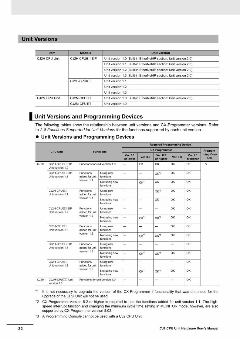
The following tables show the relationship between unit versions and CX-Programmer versions. Referto A-8 Functions Supported for Unit Versions for the functions supported by each unit version.
� Unit Versions and Programming Devices
*1 It is not necessary to upgrade the version of the CX-Programmer if functionality that was enhanced for theupgrade of the CPU Unit will not be used.
*2 CX-Programmer version 8.2 or higher is required to use the functions added for unit version 1.1. The high-speed interrupt function and changing the minimum cycle time setting in MONITOR mode, however, are alsosupported by CX-Programmer version 8.02.
*3 A Programming Console cannot be used with a CJ2 CPU Unit.
Unit Versions
Item Models Unit version
CJ2H CPU Unit CJ2H-CPU6@-EIP Unit version 1.0 (Built-in EtherNet/IP section: Unit version 2.0)
Unit version 1.1 (Built-in EtherNet/IP section: Unit version 2.0)
Unit version 1.2 (Built-in EtherNet/IP section: Unit version 2.0)
Unit version 1.3 (Built-in EtherNet/IP section: Unit version 2.0)
CJ2H-CPU6@ Unit version 1.1
Unit version 1.2
Unit version 1.3
CJ2M CPU Unit CJ2M-CPU3@ Unit version 1.0 (Built-in EtherNet/IP section: Unit version 2.0)
CJ2M-CPU1@ Unit version 1.0
Unit Versions and Programming Devices
CPU Unit Functions
Required Programming Device
CX-Programmer Program-ming Con-
soleVer. 7.1 or lower Ver. 8.0 Ver. 8.2
or higher Ver. 9.0 Ver. 9.1 or higher
CJ2H CJ2H-CPU6@-EIPUnit version 1.0
Functions for unit version 1.0 --- OK OK OK OK ---*3
CJ2H-CPU6@-EIPUnit version 1.1
Functions added for unit version 1.1
Using new functions
--- --- OK*2 OK OK
Not using new functions
--- OK*1 OK OK OK
CJ2H-CPU6@Unit version 1.1
Functions added for unit version 1.1
Using new functions
--- --- OK*2 OK OK
Not using new functions
--- --- OK OK OK
CJ2H-CPU6@-EIPUnit version 1.2
Functions added for unit version 1.2
Using new functions
--- --- --- OK OK
Not using new functions
--- OK*1 OK*1 OK OK
CJ2H-CPU6@Unit version 1.2
Functions added for unit version 1.2
Using new functions
--- --- --- OK OK
Not using new functions
--- OK*1 OK*1 OK OK
CJ2H-CPU6@-EIPUnit version 1.3
Functions added for unit version 1.3
Using new functions
--- --- --- --- OK
Not using new functions
--- OK*1 OK*1 OK OK
CJ2H-CPU6@Unit version 1.3
Functions added for unit version 1.3
Using new functions
--- --- --- --- OK
Not using new functions
--- OK*1 OK*1 OK OK
CJ2M CJ2M-CPU@@ Unit version 1.0
Functions for unit version 1.0 --- --- --- --- OK

33CJ2 CPU Unit Hardware User’s Manual
� Pull-down List for PLC Models Unit versions are not differentiated in the pull-down list for PLC models in the Change PLC DialogBox of the CX-Programmer. Select as shown in the following table regardless of the unit version.
Troubleshooting Problems with Unit Versions on the CX-Programmer
Series CPU Unit Model number PLC model in Change PLC Dialog Box in CX-Programmer ver-sion 9.0 or higher
CJ Series CJ2H CPU Unit CJ2H-CPU6@-EIPCJ2H-CPU6@
CJ2H
CJ2M CPU Unit CJ2M-CPU3@CJ2M-CPU1@
CJ2M
Problem Cause Solution
After the above message is displayed, a compiling error will be displayed on the Compile Tab Page in the Output Window.
An attempt was made to down-load a program containing instructions supported only by later unit versions or a CPU Unit to a previous unit version.
Check the program or change to a CPU Unit with a later unit ver-sion.
An attempt was to download a PLC Setup containing settings supported only by later unit ver-sions or a CPU Unit to a previous unit version.
Check the settings in the PLC Setup or change to a CPU Unit with a later unit version.
“????” is displayed in a program transferred from the PLC to the CX-Programmer.
An attempt was made to upload a program containing instruc-tions supported only by higher versions of CX-Programmer to a lower version.
New instructions cannot be uploaded to lower versions of CX-Programmer. Use a higher version of CX-Programmer.
34 CJ2 CPU Unit Hardware User’s Manual
Related Manuals
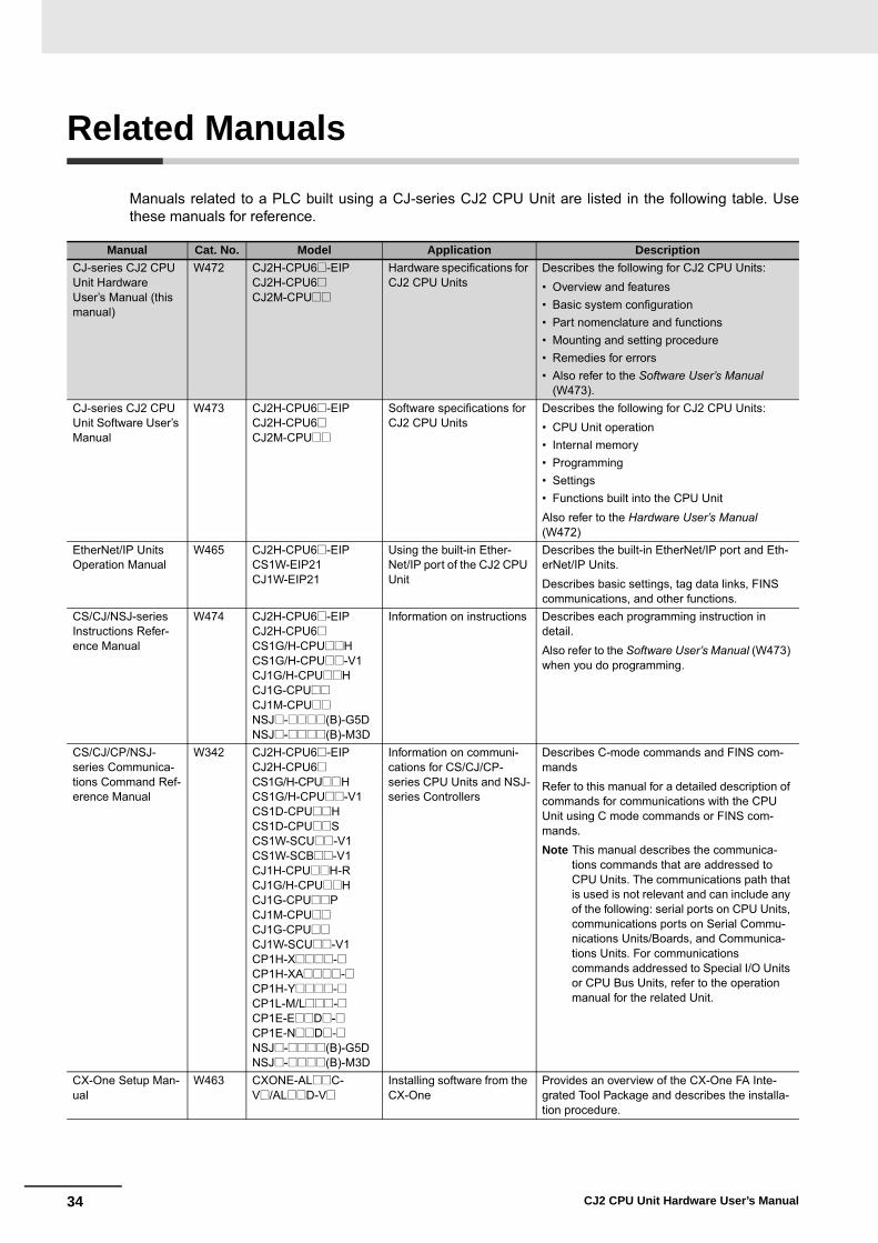
Manuals related to a PLC built using a CJ-series CJ2 CPU Unit are listed in the following table. Usethese manuals for reference.
Manual Cat. No. Model Application DescriptionCJ-series CJ2 CPU Unit Hardware User’s Manual (this manual)
W472 CJ2H-CPU6@-EIPCJ2H-CPU6@CJ2M-CPU@@
Hardware specifications for CJ2 CPU Units
Describes the following for CJ2 CPU Units:• Overview and features• Basic system configuration• Part nomenclature and functions• Mounting and setting procedure• Remedies for errors• Also refer to the Software User’s Manual
(W473).CJ-series CJ2 CPU Unit Software User’s Manual
W473 CJ2H-CPU6@-EIPCJ2H-CPU6@CJ2M-CPU@@
Software specifications for CJ2 CPU Units
Describes the following for CJ2 CPU Units:• CPU Unit operation• Internal memory• Programming• Settings• Functions built into the CPU UnitAlso refer to the Hardware User’s Manual(W472)
EtherNet/IP Units Operation Manual
W465 CJ2H-CPU6@-EIPCS1W-EIP21CJ1W-EIP21
Using the built-in Ether-Net/IP port of the CJ2 CPU Unit
Describes the built-in EtherNet/IP port and Eth-erNet/IP Units. Describes basic settings, tag data links, FINS communications, and other functions.
CS/CJ/NSJ-series Instructions Refer-ence Manual
W474 CJ2H-CPU6@-EIPCJ2H-CPU6@CS1G/H-CPU@@HCS1G/H-CPU@@-V1CJ1G/H-CPU@@HCJ1G-CPU@@CJ1M-CPU@@NSJ@-@@@@(B)-G5DNSJ@-@@@@(B)-M3D
Information on instructions Describes each programming instruction in detail.Also refer to the Software User’s Manual (W473) when you do programming.
CS/CJ/CP/NSJ-series Communica-tions Command Ref-erence Manual
W342 CJ2H-CPU6@-EIPCJ2H-CPU6@CS1G/H-CPU@@HCS1G/H-CPU@@-V1CS1D-CPU@@HCS1D-CPU@@SCS1W-SCU@@-V1CS1W-SCB@@-V1CJ1H-CPU@@H-RCJ1G/H-CPU@@HCJ1G-CPU@@PCJ1M-CPU@@CJ1G-CPU@@CJ1W-SCU@@-V1CP1H-X@@@@-@CP1H-XA@@@@-@CP1H-Y@@@@-@CP1L-M/L@@@-@CP1E-E@@D@-@CP1E-N@@D@-@NSJ@-@@@@(B)-G5DNSJ@-@@@@(B)-M3D
Information on communi-cations for CS/CJ/CP-series CPU Units and NSJ-series Controllers
Describes C-mode commands and FINS com-mandsRefer to this manual for a detailed description of commands for communications with the CPU Unit using C mode commands or FINS com-mands.Note This manual describes the communica-
tions commands that are addressed to CPU Units. The communications path that is used is not relevant and can include any of the following: serial ports on CPU Units, communications ports on Serial Commu-nications Units/Boards, and Communica-tions Units. For communications commands addressed to Special I/O Units or CPU Bus Units, refer to the operation manual for the related Unit.
CX-One Setup Man-ual
W463 CXONE-AL@@C-V@/AL@@D-V@
Installing software from the CX-One
Provides an overview of the CX-One FA Inte-grated Tool Package and describes the installa-tion procedure.

35CJ2 CPU Unit Hardware User’s Manual
CX-Programmer Operation Manual
W446 WS02-CX@@-V@ Support Software for Win-dows computers
CX-Programmer operating procedure
Describes operating procedures for the CX-Pro-grammer.Also refer to the Software User’s Manual (W473) and CS/CJ/NSJ-series Instructions Reference Manual (W474) when you do programming.
CX-Programmer Operation Manual Functions Blocks/Structured Text
W447
CX-Programmer Operation Manual SFC Programming
W469
CS/CJ/CP/NSJ-series CX-Simulator Operation Manual
W366 WS02-SIMC1-E Operating procedures for CX-Simulator Simulation Support Software for Win-dows computersUsing simulation in the CX-Programmer with CX-Pro-grammer version 6.1 or higher
Describes the operating procedures for the CX-Simulator.When you do simulation, also refer to the CX-Programmer Operation Manual (W446), Soft-ware User’s Manual (W473), and CS/CJ/NSJ-series Instructions Reference Manual (W474).
CS/CJ/CP/NSJ-series CX-Integrator Network Configura-tion Software Opera-tion Manual
W464 CXONE-AL@@C-V@/CXONE-AL@@D-V@
Network setup and moni-toring
Describes the operating procedures for the CX-Integrator.
Manual Cat. No. Model Application Description

36 CJ2 CPU Unit Hardware User’s Manual

1-1CJ2 CPU Unit Hardware User’s Manual
1
This section provides an overview of the CJ2 CPU Units.
1-1 Overview of CJ2 CPU Units . . . . . . . . . . . . . . . . . . . . . . . . . . . . . . . . . . . . . . 1-21-1-1 Overview . . . . . . . . . . . . . . . . . . . . . . . . . . . . . . . . . . . . . . . . . . . . . . . . . . . . . 1-21-1-2 CJ2 CPU Unit Features . . . . . . . . . . . . . . . . . . . . . . . . . . . . . . . . . . . . . . . . . . 1-4
1-2 Basic Operating Procedure . . . . . . . . . . . . . . . . . . . . . . . . . . . . . . . . . . . . . 1-11
1-3 Specifications . . . . . . . . . . . . . . . . . . . . . . . . . . . . . . . . . . . . . . . . . . . . . . . . 1-121-3-1 General Specifications . . . . . . . . . . . . . . . . . . . . . . . . . . . . . . . . . . . . . . . . . . 1-121-3-2 Performance Specifications . . . . . . . . . . . . . . . . . . . . . . . . . . . . . . . . . . . . . . 1-131-3-3 Function Specifications . . . . . . . . . . . . . . . . . . . . . . . . . . . . . . . . . . . . . . . . . 1-19
Overview

1 Overview
1-2 CJ2 CPU Unit Hardware User’s Manual
1-1 Overview of CJ2 CPU Units
The SYSMAC CJ2-series CPU Units are multi-functional CPU Units that provide the following features.
� Fast, with Large Memory CapacityBasic performance is faster and memory capacity has been increased to provide ample capabilityfor machine control.
� Built-in EtherNet/IP Port (CJ2H-CPU6@-EIP and CJ2M-CPU3@ Only)The CJ2 CPU Units support the EtherNet/IP open network as a standard feature. Universal Ethernetcommunications, such as data links between PLCs, message communications between PLCs, andFTP transfers, are all possible from a peripheral device connection.
� General-purpose Networks for Support Software InterfaceSupport Software and devices can be easily connected using commercially available cable to gen-eral-purpose networks via USB and EtherNet/IP ports. (The EtherNet/IP port is provided only on theCJ2H-CPU6@-EIP and CJ2M-CPU3@.)
� Tag Access (CJ2H-CPU6@-EIP and CJ2M-CPU3@ Only) CJ2 CPU Units have a tag name server to manage tag names and I/O addresses. This enablesaccess from external devices using tag names, without needing to know the I/O addresses.
� Synchronous Unit Operation (CJ2H CPU Unit with Unit Version 1.1 or Later) The timing of processing performed by CPU Bus Units and Special I/O Units can be synchronized.This minimizes fluctuations in timing from input and processing to outputs, making it easier to ensureapplication performance.
� Easier ProgrammingCJ2 CPU Units offer a highly readable programming environment, including features such asaddressing DM and EM Area bits, setting address offsets, and using array variables.
� Improved DebuggingOnline editing and data tracing have been improved, greatly increasing the efficiency of debugging.
� More Serial Communications Ports (CJ2M-CPU3@ Only) With the standard CJ2M CPU Unit (CJ2M-CPU3@) you can add an RS-232C or RS-422A/485Option Board to the standard-feature EtherNet/IP port to increase the number of serial communica-tions ports.
1-1-1 Overview
1-3
1 Overview
CJ2 CPU Unit Hardware User’s Manual
1-1 Overview
of CJ2 C
PU U
nits
1
1-1-1 Overview
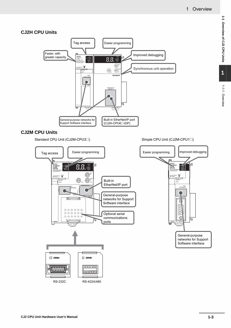
CJ2H CPU Units
CJ2M CPU UnitsStandard CPU Unit (CJ2M-CPU3@) Simple CPU Unit (CJ2M-CPU1@)
Tag access Easier programming
General-purpose networks for Support Software interface
Improved debuggingFaster, with greater capacity
Synchronous unit operation
Built-in EtherNet/IP port(CJ2H-CPU6@-EIP)
RS-232C RS-422A/485
Tag access Easier programming
Built-inEtherNet/IP port
Optional serial communicationsports
Easier programming Improved debugging
General-purposenetworks for Support Software interface
General-purposenetworks for Support Software interface
1 Overview
1-4 CJ2 CPU Unit Hardware User’s Manual
� High-speed ProcessingHigh-speed processing is possible for basic instructions (0.016 μs min. for CJ2H and 0.04 μs min.for CJ2M), special instructions (0.05 μs min. for CJ2H and 0.06 μs min. for CJ2M), and immediaterefreshing (0.99 μs min. for CJ2H and 1.26 μs min. for CJ2M).
� Large Program CapacityThe CJ2 CPU Units provide a large program capacity of up to 400 Ksteps.
� Special Function Block Definition Area (CJ2M Only)With a CJ2M CPU Unit, a special area called the FB Program Area is provided to store functionblock definitions. (The FB Program Area holds 20K steps.) This allows you to use function blocks tomake program components and structures from previous programs while reducing the usage of theUser Program Area. And any function block definitions that would exceed the FB Program Area arestored in the User Program Area.
� Large Data Memory CapacityThe CJ2 CPU Units provide a large EM Area capacity of up to 800 Kwords (25 banks).
� Up to 128 Cyclic TasksThe user program can be divided into up to 128 tasks. Using smaller task programs makes it easierto structure programs and contributes to shorter cycle times.
� Enhanced Performance for Executing Interrupt Tasks (CJ2H CPU Units with Unit Version 1.1 or Later) With CJ2H CPU Units with unit version 1.1, overhead time for interrupt tasks is approximately 20%less than for unit version 1.0 even for normal usage. Also, by using High-speed interrupt function, itis possible to improve execution performance as shown below with certain restrictions. • Greatly reduce overhead time for interrupt tasks (interrupt task startup time + return time to cyclic
tasks).
Example: For I/O interrupt tasks, the time for normal operation is 37 μs but the time is 25 μs ifHigh-speed interrupt function is used.
• Minimum interval setting of 0.1 ms for one of Scheduled Interrupt Tasks (For unit version 1.0, the minimum interval is 0.2 ms.)
1-1-2 CJ2 CPU Unit Features
Fast, with Large Memory Capacity

1-5
1 Overview
CJ2 CPU Unit Hardware User’s Manual
1-1 Overview
of CJ2 C
PU U
nits
1
1-1-2 CJ2 C
PU
Unit Features
The CJ2 CPU Units provide as standard equipment a built-in EtherNet/IP port that supports the sameFINS Ethernet functions as an Ethernet Unit (including features such as an FTP server and time coordi-nation) as well as the EtherNet/IP open network.
� High-speed, High-capacity Data Links with User-set Refresh CyclesThe CJ2 CPU Units provide high-speed, high-capacity data links, and refresh cycles can be set indi-vidually for each data link area.
In addition, using the EtherNet/IP DataLink Tool makes it possible to set the data links using an inter-face similar to that of the Controller Link automatic data link setup.
� Built-in USB and EtherNet/IP PortsA commercially available USB cable can be used to connect to the PLC directly from a USB port ona personal computer. In addition, with the CJ2H-CPU6@-EIP or CJ2M-CPU3@, a PLC on the Ether-Net/IP network can be accessed via USB.
� Prevent Connecting to the Wrong PLC by Using PLC Names from Support SoftwareA user-set PLC name can be recorded in a CJ2 CPU Unit. When using Support Software to connectonline to a PLC, verification of the PLC name prevents incorrect connections from the Support Soft-ware.
Built-in EtherNet/IP Port (CJ2H-CPU6@-EIP and CJ2M-CPU3@ Only)
General-purpose Networks for Support Software Interface
EtherNet/IP
High speed
The refresh cycle can be set individually for each area.
High capacity
CJ2 CPU Unit CJ2 CPU Unit

1 Overview
1-6 CJ2 CPU Unit Hardware User’s Manual
� Network Symbols (Tags) for Flexible Support of Program ChangesThe CJ2 CPU Units support network symbols (tags). They have an internal tag name server thatenables them to store tag names and addresses in advance in symbol tables in the CPU Units. Tagsenable the following features.
Data links can be set using tags.With data links on an EtherNet/IP network, send and receive areas can be specified using symbolsrather than addresses. This enables flexible support for design changes by allowing the data linkareas set by tags to remain unchanged, while simply changing the symbol tables that contain the tagnames and addresses.
Access from host devices is enabled using tags.Tags can be used for access from host devices, such as touch panel NS-series Programmable Ter-minals. This makes the creation of host screens and programs at devices such as PTs much moreconvenient.
Automatic tag allocation makes it unnecessary to know the addresses.Automatic allocation of tags in the high-capacity EM Area, using automatic address allocation in CX-Programmer symbol tables, enables data link design and access from host devices without having topay attention to addresses.
Tag Access (CJ2H-CPU6@-EIP and CJ2M-CPU3@ Only)
Data links enabled by names
EtherNet/IP
Examples: Inputs from a to bInputs from c to d
CJ2 CPU Unit CJ2 CPU Unit
EtherNet/IP
Touch PanelNS-series PTExamples: Writing to a
Reading from bMiddlewareSupporting EtherNet/IP
CJ2 CPU UnitCJ2 CPU Unit
Host application, such as SCADAAccess is possible using tags.
PERIPHERAL
ERR/AL MRUN
INH
COMMBKUP
PRPHLCONTROLLER
CPU64-EIPCJ2HSYSMAC
PROGRAMMABLE
PORT
OPEN
BUSYMCPWR
NSMS
COMM
10M100M
Tags are allocated in a high-capacity area.
Designing is performed by using only tags, with no need to pay attention to addresses.
EtherNet/IP
Specified by tag a.
CJ2 CPU Unit

1-7
1 Overview
CJ2 CPU Unit Hardware User’s Manual
1-1 Overview
of CJ2 C
PU U
nits
1
� A CJ2 CPU Unit can synchronize the start of the processing performed by CPU Bus Units and Special I/O Units to a specified cycle. Synchronous data refreshing can be used between the CJ2H CPU Unit and Synchronous Units,*and the refreshed data can be used in operations in a synchronous interrupt task. This enables mul-tiaxis control with minimal fluctuations in the timing from inputs and processing to outputs. This pro-vides support for motion applications that require precise timing, such as electronic cam control.
* Synchronous Units are CPU Bus Units and Special I/O Units that support the synchronous unit operation func-tion. The following Synchronous Units are available as of December 2009: CJ1W-NC214/234/414/434 PositionControl Units.
� Address offsets can be specified.When an address is specified for an instruction operand, an offset can be specified in brackets afterthe address to offset it. For example, by setting a word address in brackets to specify the offset, theaddress can be dynamically specified according to the contents of that word.
ExampleW0.00[D0]: W0.00 is the starting address and the contents of D0 is the offset. If D0 is &3, thenW0.03 is specified.
� Symbols can be specified for array variable subscripts.By specifying symbols for array variable subscripts, elements can be dynamically specified accord-ing to the values of the symbols.
Examplea[b]: The value of symbol b specifies the element for array variable a[ ].
Synchronous Unit Operation (CJ2H CPU Units with Unit Version 1.1 or Later)
Easier Programming
CJ2H CPU Units (with unit version 1.1 or later)Example:Electronic cam control
Synchronous UnitsExample:Position Control Units
Example:High-speed Counter Unit
Synchronous data refreshing
Encoder
Motor drive
Servomotor
Several servomotors are controlled synchronously based on the operation of the encoder.
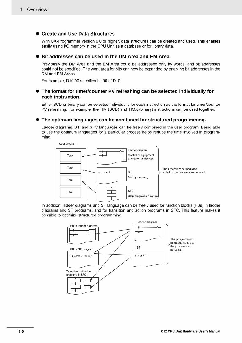
1 Overview
1-8 CJ2 CPU Unit Hardware User’s Manual
� Create and Use Data StructuresWith CX-Programmer version 9.0 or higher, data structures can be created and used. This enableseasily using I/O memory in the CPU Unit as a database or for library data.
� Bit addresses can be used in the DM Area and EM Area.Previously the DM Area and the EM Area could be addressed only by words, and bit addressescould not be specified. The work area for bits can now be expanded by enabling bit addresses in theDM and EM Areas.
For example, D10.00 specifies bit 00 of D10.
� The format for timer/counter PV refreshing can be selected individually for each instruction.Either BCD or binary can be selected individually for each instruction as the format for timer/counterPV refreshing. For example, the TIM (BCD) and TIMX (binary) instructions can be used together.
� The optimum languages can be combined for structured programming.Ladder diagrams, ST, and SFC languages can be freely combined in the user program. Being ableto use the optimum languages for a particular process helps reduce the time involved in program-ming.
In addition, ladder diagrams and ST language can be freely used for function blocks (FBs) in ladderdiagrams and ST programs, and for transition and action programs in SFC. This feature makes itpossible to optimize structured programming.
User program
Task
Task
Task
Task SFC
Step progression control
Ladder diagram
Control of equipment and external devices
ST
Math processing
a := a + 1;The programming language suited to the process can be used.
Transition and action programs in SFC
Ladder diagram
ST
FB_(A:=B,C=>D); a := a + 1;
The programming language suited to the process can be used.
FB in ladder diagram
FB in ST program
1-9
1 Overview
CJ2 CPU Unit Hardware User’s Manual
1-1 Overview
of CJ2 C
PU U
nits
1
1-1-2 CJ2 C
PU
Unit Features
� Reduced Effect on Cycle Time from Online EditingThe additional cycle time due to online editing has been reduced to approx. 1 ms, minimizing theeffects on equipment operation during debugging.
� Fast, High-capacity Data TracingUp to 32 Kwords of data can be traced (8 times more than previously), with ample trigger conditions,and data can be traced continuously for long periods of time.
� Force-set/Reset Bits in Specified EM Area Banks With CX-Programmer version 8.3 or higher, a parameter can be set to enable force-setting/resettingbits in specified EM Area banks. (This function is supported only by the CJ2H CPU Units with unitversion 1.2 or later and CJ2M CPU Units.)
Improved Debugging
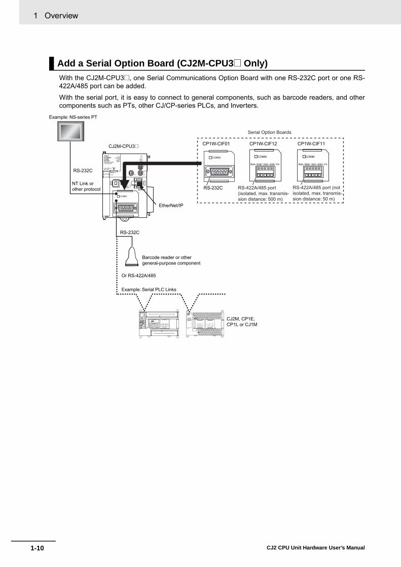
1 Overview
1-10 CJ2 CPU Unit Hardware User’s Manual
With the CJ2M-CPU3@, one Serial Communications Option Board with one RS-232C port or one RS-422A/485 port can be added.
With the serial port, it is easy to connect to general components, such as barcode readers, and othercomponents such as PTs, other CJ/CP-series PLCs, and Inverters.
Add a Serial Option Board (CJ2M-CPU3@ Only)
COMM
RDA- RDB+ SDA- SDB+ FG
COMM
RDA- RDB+ SDA- SDB+ FG
COMM
RS-232C
CJ2M-CPU3@ CP1W-CIF01
RS-232C
CP1W-CIF12 CP1W-CIF11
EtherNet/IP
RS-232C
Example: NS-series PT
NT Link or other protocol
Barcode reader or other general-purpose component
Or RS-422A/485
Example: Serial PLC Links
CJ2M, CP1E, CP1L or CJ1M
Serial Option Boards
RS-422A/485 port (isolated, max. transmis-sion distance: 500 m)
RS-422A/485 port (not isolated, max. transmis-sion distance: 50 m)
COMM

1-11
1 Overview
CJ2 CPU Unit Hardware User’s Manual
1-2 Basic O
perating Procedure
1
1-1-2 CJ2 C
PU
Unit Features
1-2 Basic Operating Procedure
In general, use the following procedure.
1. Setting Devices and Hardware
2. Wiring
3. Connecting Online to the PLC
4. I/O Allocations
5. Software Setup
6. Creating the Program
8. Basic Program Operation
Wire the power supply, I/O, and communications. Refer to the following manuals.
Connect the personal computer online to the PLC.
Using the CX-Programmer, allocate I/O memory in the CPU Unit to the mounted Units.
Make the PLC software settings.
Create the program using the CX-Programmer.
7. Checking Operation
Set the operating mode to RUN mode to start operation.
Mount the Power Supply Unit, the CPU Unit, the other Units, and the End Covers. Set the DIP switch and rotary switches as required.
Refer to Section 3 Nomenclature and Functions and Section 5 Installation in the CJ2 CPU Unit Hardware User’s Manual (Cat. No. W472).
Refer to Section 5 Installation in the CJ2 CPU Unit Hardware User’s Manual (Cat. No. W472).Refer to Section 11 Programming Devices and Communications in the CJ2 CPU Unit Software User’s Manual (Cat. No. W473).
Refer to Section 4 Support Software in the CJ2 CPU Unit Hardware User’s Manual (Cat. No. W472)
Refer to Section 8 I/O Allocations and Unit Settings in the CJ2 CPU Unit Software User’s Manual (Cat. No. W473)
• CPU Unit initialization: Refer to Section 4 CPU Unit Initialization in the CJ2 CPU Unit Software User’s Manual (Cat. No. W473).
• DM Area Settings for Special I/O Units and CPU Bus Units: Refer to Section 8 I/O Allocations and Unit Settings in the CJ2 CPU Unit Software User’s Manual (Cat. No. W473).
• PLC Setup: Refer to Section 9 PLC Setup in the CJ2 CPU Unit Software User’s Manual (Cat. No. W473).
Refer to Section 5 Understanding Programming in the CJ2 CPU Unit Software User’s Manual(Cat. No. W473).
Refer to 10-7 Debugging in the CJ2 CPU Unit Software User’s Manual (Cat. No. W473).
Check the I/O wiring and the AR Area settings, and perform trial operation. The CX-Programmer can be used for monitoring and debugging.

1 Overview
1-12 CJ2 CPU Unit Hardware User’s Manual
1-3 Specifications
* Without a Serial Option Board
1-3-1 General Specifications
ItemCJ2H- CJ2M-
CPU64(-EIP) CPU65(-EIP) CPU66(-EIP) CPU67(-EIP) CPU68(-EIP) CPU1@ CPU3@
Enclosure Mounted in a panel
Grounding Less than 100 Ω
CPU Rack Dimensions CJ2H-CPU6@-EIP: 90 mm × 65 mm × 80 mm (H × D × W)
CJ2H-CPU6@: 90 mm × 65 mm × 49 mm (H × D × W)
90 mm ×75 mm ×31 mm (H × D × W)
90 mm ×75 mm ×62 mm (H × D × W)
Weight CJ2H-CPU6@-EIP: 280 g or less
CJ2H-CPU6@: 190 g or less
130 g or less
190 g or less*
Current Consumption CJ2H-CPU6@-EIP: 5 VDC, 0.82 A
CJ2H-CPU6@: 5 VDC, 0.42 A
5 VDC, 0.5 A
5 VDC, 0.7 A
Use Environment Ambient Operating Temperature 0 to 55°C
Ambient Operating Humidity 10% to 90%
Atmosphere Must be free from corrosive gases.
Ambient Storage Temperature −20 to 70°C (excluding battery)
Altitude 2,000 m or less
Pollution Degree 2 or less: Conforms to JIS B3502 and IEC 61131-2.
Noise Immunity 2 kV on power supply line (Conforms to IEC 61000-4-4.)
Overvoltage Category Category II: Conforms to JIS B3502 and IEC 61131-2.
EMC Immunity Level Zone B
Vibration Resistance Conforms to IEC60068-2-6.
5 to 8.4 Hz with 3.5-mm amplitude, 8.4 to 150 Hz
Acceleration of 9.8 m/s2 for 100 min in X, Y, and Z directions (10 sweeps of 10 min each = 100 min total)
Shock Resistance Conforms to IEC60068-2-27.
147 m/s2, 3 times in X, Y, and Z directions (100 m/s2 for Relay Output Units)
Battery Life 5 years at 25°C
Model CJ1W-BAT01
Applicable Standards Conforms to cULus, EC, NK, and LR Directives. Conforms to cULus and EC Directives.

1-13
1 Overview
CJ2 CPU Unit Hardware User’s Manual
1-3 Specifications
1
1-3-2 Performance S
pecifications
*1 The following times are added if EtherNet/IP data tag links are used for the CJ2H-CPU6@-EIP.
Normal operation: 100 μs + Number of transfer words x 0.33 μs
High-speed interrupt function enabled: 100 μs + Number of transfer words × 0.87 μs
The following time must be added when using EtherNet/IP tag data links for the CJ2M-CPU3@.
100 μs + (Number of words transferred × 1.8 μs)*2 This applies when high-speed interrupts are used.
1-3-2 Performance Specifications
ItemsCJ2H- CJ2M-
CPU64(-EIP)
CPU65(-EIP)
CPU66(-EIP)
CPU67(-EIP)
CPU68(-EIP)
CPU11/31
CPU12/32
CPU13/33
CPU14/34
CPU15/35
User Memory 50K steps
100K steps
150K steps
250K steps
400K steps
5K steps 10K steps
20K steps
30K steps
60K steps
I/O Bits 2,560 bits
Process-ing Speed
Overhead Processing Time Normal Mode: CJ2H-CPU@@-EIP: 200 μs*1
CJ2H-CPU@@: 100 μs
Normal Mode: CJ2M-CPU3@: 270 μs*1
CJ2M-CPU1@: 160 μs
Execution Time Basic Instructions: 0.016 μs min.;Special Instructions: 0.048 μs min.
Basic Instructions: 0.04 μs min.;Special Instructions: 0.06 μs min.
Interrupts I/O Inter-rupts and External Interrupts
Interrupt task startup time: 26 μs or 17 μs*2 (30 μs for unit version 1.0) Return times to cyclic tasks: 11 μs or 8 μs*2 (15 μs for unit version 1.0)
Interrupt task startup time: 31 μsReturn times to cyclic tasks: 10 μs
Scheduled Interrupts
Minimum time interval: 0.2 ms or 0.1 ms*2 (set in 0.1-ms increments)
Minimum time interval: 0.4 ms (set in 0.1-ms increments)
Interrupt task startup time: 22 μs or 13 μs*2 (27 μs for unit version 1.0) Return time to cyclic task: 11 μs or 8 μs*2 (15 μs for unit version 1.0)
Interrupt task startup time: 30 μsReturn time to cyclic task: 11 μs
Maximum Number of Connectable Units Total per CPU Rack or Expansion Rack: 10 Units max.;Total per PLC: 40 Units max.
Basic I/O Units No limitHowever, a maximum of two CJ1W-INT01 Interrupt Input Units can be mounted.
Special I/O Units Units for up to 96 unit numbers can be mounted. (Unit numbers run from 0 to 95. Units are allocated between 1 and 8 unit numbers.)
CPU Bus Units CJ2H-CPU6@-EIP: 15 Units max. CJ2H-CPU6@: 16 Units max.
CJ2M-CPU3@: 15 Units max. CJ2M-CPU1@: 16 Units max.
Slots for which interrupts can be used
CJ2H-CPU6@-EIP: Slots 0 to 3 on CPU RackCJ2H-CPU6@: Slots 0 to 4 on CPU Rack
Slots 0 to 4 on CPU Rack
Maximum Number of Expansion Racks 3 max.
CIO Area I/O Area 2,560 bits (160 words): Words CIO 0000 to CIO 0159
Link Area 3,200 bits (200 words): Words CIO 1000 to CIO 1199
Synchronous Data Refresh Area
1,536 bits (96 words): Words CIO 1200 to CIO 1295 ---
CPU Bus Unit Area 6,400 bits (400 words): Words CIO 1500 to CIO 1899
Special I/O Unit Area 15,360 bits (960 words): Words CIO 2000 to CIO 2959
Serial PLC Link Words --- 1,440 bits (90 words): Words CIO 3100 to CIO 3189
DeviceNet Area 9,600 bits (600 words): Words CIO 3200 to CIO 3799
Internal I/O Area 3,200 bits (200 words): Words CIO 1300 to CIO 149937,504 bits (2,344 words): Words CIO 3800 to CIO 6143
Cannot be used for external I/O.
Work Area 8,192 bits (512 words): Words W000 to W511
Cannot be used for external I/O.
Holding Area 8,192 bits (512 words): Words H000 to H511
Bits in this area maintain their ON/OFF status when PLC is turned OFF or operating mode is changed.
Words H512 to H1535: These words can be used only for function blocks. They can be used only for function block instances (i.e., they are allocated only for internal variables in function blocks).

1 Overview
1-14 CJ2 CPU Unit Hardware User’s Manual
*3 A960 to A1471 and A10000 to A11535 cannot be accessed by CPU Bus Units, Special I/O Units, PTs, and Support Soft-ware that do not specifically support the CJ2 CPU Units.
*4 Bits in the EM Area can be addressed either by bit or by word. These bits cannot be addressed by CPU Bus Units, Spe-cial I/O Units, PTs, and Support Software that do not specifically support the CJ2 CPU Units.
*5 EM banks D to 18 cannot be accessed by CPU Bus Units, Special I/O Units, PTs, and Support Software that do not spe-cifically support the CJ2 CPU Units.
*6 With CJ2H CPU Units with unit version 1.2 or later, force-setting/resetting bits in the EM Area is possible either for banksthat have been specified for automatic address allocation or for banks specified for the EM Area force-set/reset function.With CJ2M CPU Units, force-setting/resetting bits in the EM Area is possible only for banks specified for the EM Areaforce-set/reset function.
ItemsCJ2H- CJ2M-
CPU64(-EIP)
CPU65(-EIP)
CPU66(-EIP)
CPU67(-EIP)
CPU68(-EIP)
CPU11/31
CPU12/32
CPU13/33
CPU14/34
CPU15/35
Auxiliary Area Read-only: 31,744 bits (1,984 words)
• 7,168 bits (448 words): Words A0 to A447
• 24,576 bits (1,536 words): Words A10000 to A11535*3
Read/write: 16,384 bits (1,024 words) in words A448 to A1471*3
Temporary Area 16 bits: TR0 to TR15
Timer Area 4,096 timer numbers (T0000 to T4095 (separate from counters))
Counter Area 4,096 counter numbers (C0000 to C4095 (separate from timers))
DM Area 32k words*4
• DM Area words for Special I/O Units: D20000 to D29599 (100 words × 96 Units)• DM Area words for CPU Bus Units: D30000 to D31599 (100 words × 16 Units)
EM Area 32k words/bank × 25 banks max.: E00_00000 to E18_32767 max.*4, *5
32k words/bank × 4 banks max.: E00_00000 to E3_32767 max.*4
32K words ×4 banks
32K words ×4 banks
32Kwords ×10 banks
32K words ×15 banks
32K words ×25 banks
32K words × 1 bank 32K words × 4 banks
Banks for which bits can be force-set/reset*6
Using EM Area force-setting/reset-ting
Banks 0 to 3 hex
Banks 0 to 3 hex
Banks 0 to 9 hex
Banks 0 to E hex
Banks 0 to 18 hex
Bank 0 hex Banks 0 to 3 hex
Using auto-matic address allo-cation speci-fications
Bank 3 hex
Bank 3 hex
Banks 6 to 9 hex
Banks 7 to E hex
Banks 11 to 18 hex
---
Index Registers IR0 to IR15
These are special registers for storing PLC memory addresses for indirect addressing. (Index Registers can be set so that they are unique in each task or so that they are shared by all tasks.)
Cyclic Task Flag Area 128 flags
Memory Card 128 MB, 256 MB, or 512 MB
Operating Modes PROGRAM Mode: Programs are not executed. Preparations can be executed prior to program execution in this mode.
MONITOR Mode: Programs are executed, and some operations, such as online editing, and changes to present values in I/O memory, are enabled in this mode.
RUN Mode: Programs are executed. This is the normal operating mode.
Execution Mode Normal Mode
Programming Languages Ladder Logic (LD)Sequential Function Charts (SFC)Structured Text (ST)Instruction Lists (IL)
Function Blocks
Maximum number of defini-tions
2,048 256 2,048
Maximum number of instances
2,048 256 2,048
FB Program Area --- 20K steps

1-15
1 Overview
CJ2 CPU Unit Hardware User’s Manual
1-3 Specifications
1
1-3-2 Performance S
pecifications
*7 Supported only by the CJ2H-CPU6@-EIP and CJ2M-CPU3@.*8 This data type cannot be used in Function blocks. *9 This data type can be used only in Function blocks. *10 Supported only when CX-Programmer version 9.0 or higher is used.
ItemsCJ2H- CJ2M-
CPU64(-EIP)
CPU65(-EIP)
CPU66(-EIP)
CPU67(-EIP)
CPU68(-EIP)
CPU11/31
CPU12/32
CPU13/33
CPU14/34
CPU15/35
Tasks Type of Tasks Cyclic tasksInterrupt tasks (Power OFF interrupt tasks, scheduled interrupt tasks, I/O interrupt tasks, and external interrupt tasks)
Number of Tasks Cyclic tasks: 128
Interrupt tasks: 256(Interrupt tasks can be defined as cyclic tasks to create extra cyclic tasks. Therefore, the total number of cyclic tasks is actually 384 max.)
Symbols (Vari-ables)
Type of Symbols Local symbols: Can be used only within a single task in the PLC.
Global symbols: Can be used in all tasks in the PLC.
Network symbols (tags)*8: I/O memory in the CPU Unit can be externally accessed using sym-bols, depending on parameter settings.
Data Type of Symbols BOOL (bit)
UINT (one-word unsigned binary)
UDINT (two-word unsigned binary)
ULINT (four-word unsigned binary)
INT (one-word signed binary)
DINT (two-word signed binary)
LINT (four-word signed binary)
UINT BCD (one-word unsigned BCD)*8
UDINT BCD (two-word unsigned BCD)*8
ULINT BCD (four-word unsigned BCD)*8
REAL (two-word floating-point)
LREAL (four-word floating-point)
CHANNEL (word)
NUMBER (constant or number)
WORD (one-word hexadecimal)
DWORD (two-word hexadecimal)
LWORD (four-word hexadecimal)
STRING (1 to 255 ASCII characters)
TIMER (timer)*9
COUNTER (counter)*9
User-defined data types (data structures)*10
Maximum Size of Symbol 32k words
Array Symbols (Array Variables) One-dimensional arrays
Number of Array Elements 32,000 elements max.
Number of Registrable Network Symbols (Tags)*7
20,000 max. 2,000 max.
Length of Network Symbol (Tag) Name*7 255 bytes max.
Encoding of Network Symbols (Tags)*7 UTF-8

1 Overview
1-16 CJ2 CPU Unit Hardware User’s Manual
ItemsCJ2H- CJ2M-
CPU64(-EIP)
CPU65(-EIP)
CPU66(-EIP)
CPU67(-EIP)
CPU68(-EIP)
CPU11/31
CPU12/32
CPU13/33
CPU14/34
CPU15/35
Data Tracing Memory Capacity 8,000 words 16,000 words
32,000 words 8,000 words
(Up to 32k words x 25 banks when EM is spec-ified in CX-Programmer)
(Up to 32k words x 4 banks when EM is speci-fied in CX-Programmer)
Number of Samplings Bits = 31, one-word data =16, two-word data = 8, four-word data = 4
Sampling Cycle 1 to 2,550 ms (Unit: 1 ms)
Trigger Conditions ON/OFF of specified bitData comparison of specified wordData size: 1 word, 2 words, 4 wordsComparison Method: Equals (=), Greater Than (>), Greater Than or Equals (≥), Less Than (<), Less Than or Equals (≤), Not Equal (≠)
Delay Value −32,768 to +32,767 ms
File Memory Memory Card (128, 256, or 512 Mbytes) (Use the Memory Cards provided by OMRON.)
EM file memory (Part of the EM Area can be converted for use as file memory.)
Source/Com-ment Memory
Program source, comments, program index, and symbol table
Capacity: 3.5 Mbytes Capacity: 1 Mbytes
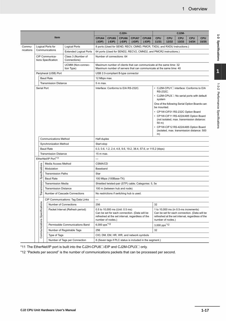
1-17
1 Overview
CJ2 CPU Unit Hardware User’s Manual
1-3 Specifications
1
1-3-2 Performance S
pecifications
*11 The EtherNet/IP port is built into the CJ2H-CPU6@-EIP and CJ2M-CPU3@ only. *12 “Packets per second” is the number of communications packets that can be processed per second.
ItemCJ2H- CJ2M-
CPU64(-EIP)
CPU65(-EIP)
CPU66(-EIP)
CPU67(-EIP)
CPU68(-EIP)
CPU11/31
CPU12/32
CPU13/33
CPU14/34
CPU15/35
Commu-nications
Logical Ports for Communications
Logical Ports 8 ports (Used for SEND, RECV, CMND, PMCR, TXDU, and RXDU instructions.)
Extended Logical Ports 64 ports (Used for SEND2, RECV2, CMND2, and PMCR2 instructions.)
CIP Communica-tions Specification
Class 3 (Number of Connections)
Number of connections: 64
UCMM (Non-connec-tion Type)
Maximum number of clients that can communicate at the same time: 32Maximum number of servers that can communicate at the same time: 40
Peripheral (USB) Port USB 2.0-compliant B-type connector
Baud Rate 12 Mbps max.
Transmission Distance 5 m max.
Serial Port Interface: Conforms to EIA RS-232C. • CJ2M-CPU1@ interface: Conforms to EIA RS-232C.
• CJ2M-CPU3@: No serial ports with default system
One of the following Serial Option Boards can be mounted.
• CP1W-CIF01 RS-232C Option Board• CP1W-CIF11 RS-422A/485 Option Board
(not isolated, max. transmission distance: 50 m)
• CP1W-CIF12 RS-422A/485 Option Board (isolated, max. transmission distance: 500 m)
Communications Method Half-duplex
Synchronization Method Start-stop
Baud Rate 0.3, 0.6, 1.2, 2.4, 4.8, 9.6, 19.2, 38.4, 57.6, or 115.2 (kbps)
Transmission Distance 15 m max.
EtherNet/IP Port*11 ---
Tran
smis
sion
Spe
cific
atio
ns Media Access Method CSMA/CD
Modulation Baseband
Transmission Paths Star
Baud Rate 100 Mbps (100Base-TX)
Transmission Media Shielded twisted-pair (STP) cable; Categories: 5, 5e
Transmission Distance 100 m (between hub and node)
Number of Cascade Connections No restrictions if switching hub is used.
Com
mun
icat
ions
Spe
cific
atio
ns
CIP Communications: Tag Data Links ---
Number of Connections 256 32
Packet Interval (Refresh period) 0.5 to 10,000 ms (Unit: 0.5 ms)Can be set for each connection. (Data will be refreshed at the set interval, regardless of the number of nodes.)
1 to 10,000 ms (in 0.5-ms increments) Can be set for each connection. (Data will be refreshed at the set interval, regardless of the number of nodes.)
Permissible Communications Band 6,000 pps*12 3,000 pps*12
Number of Registrable Tags 256 32
Type of Tags CIO, DM, EM, HR, WR, and network symbols
Number of Tags per Connection 8 (Seven tags if PLC status is included in the segment.)

1 Overview
1-18 CJ2 CPU Unit Hardware User’s Manual
*13 Large Forward Open (CIP optional specification) must be supported in order for 505 to 1,444 bytes to be used as the datasize. Application is supported between CS/CJ-series PLCs. When connecting to devices from other manufacturers, makesure that the devices support the Large Forward Open specification.
*14 If the maximum number is exceeded, refreshing will require more than one CPU Unit cycle.*15 When changing parameters, however, the EtherNet/IP port where the change is made will be restarted. In addition, a tim-
eout will temporarily occur at the other node that was communicating with that port, and it will then recover automatically.*16 The EtherNet/IP port supports an IGMP client, so unnecessary multicast packets are filtered by using a switching hub that
supports IGMP snooping.
ItemCJ2H- CJ2M-
CPU64(-EIP)
CPU65(-EIP)
CPU66(-EIP)
CPU67(-EIP)
CPU68(-EIP)
CPU11/31
CPU12/32
CPU13/33
CPU14/34
CPU15/35
Commu-nications
Com
mun
icat
ions
Spe
cific
atio
ns
Maximum Link Data Size per Node 184,832 words 640 words
Maximum Data Size per Connection 252 or 722 words*13
(Data is synchronized within each connection.)20 words (Data is synchronized within each connection.)
Number of Registrable Tag Set 256 (1 connection = 1 segment) 32 (1 connection = 1 segment)
Maximum Tag Set Size 722 words (One word is used when PLC status is included in the segment.)
20 words (One word is used when PLC sta-tus is included in the segment.)
Maximum Number of Tags Refresh-able in a Single Cycle of CPU Unit*14
Output/send (CPU Unit to EtherNet/IP): 256Input/receive (EtherNet/IP to CPU Unit): 256
Output/send (CPU Unit to EtherNet/IP): 32Input/receive (EtherNet/IP to CPU Unit): 32
Data Size Refreshable in a Single Cycle of CPU Unit*14
Output/send (CPU to EtherNet/IP): 6,432 wordsInput/receive (EtherNet/IP to CPU): 6,432 words
Output/send (CPU Unit to EtherNet/IP): 640 wordsInput/receive (EtherNet/IP to CPU Unit): 640 words
Change of Tag Data Link Parameter Settings during Operation
OK*15
Multi-cast Packet Filter*16 OK
CIP Communications: Explicit Messages ---
Class 3 (Number of Connections) Number of connections: 128
UCMM (Non-connection Type) Maximum number of clients that can communi-cate at the same time: 32Maximum number of servers that can commu-nicate at the same time: 32
Maximum number of clients that can commu-nicate at the same time: 16Maximum number of servers that can com-municate at the same time: 16
CIP Routing OK (CIP routing is enabled for the following remote Units: CJ1W-EIP21, CJ2H-CPU6@-EIP, CJ2M-CPU3@, and CS1W-EIP21.)
FINS Communications ---
FINS/UDP OK
FINS/TCP 16 connections max.
EtherNet/IP Conformance Test Conforms to A5.
EtherNet/IP Interface 10Base-T/100Base-TXAuto Negotiation/Fixed Setting
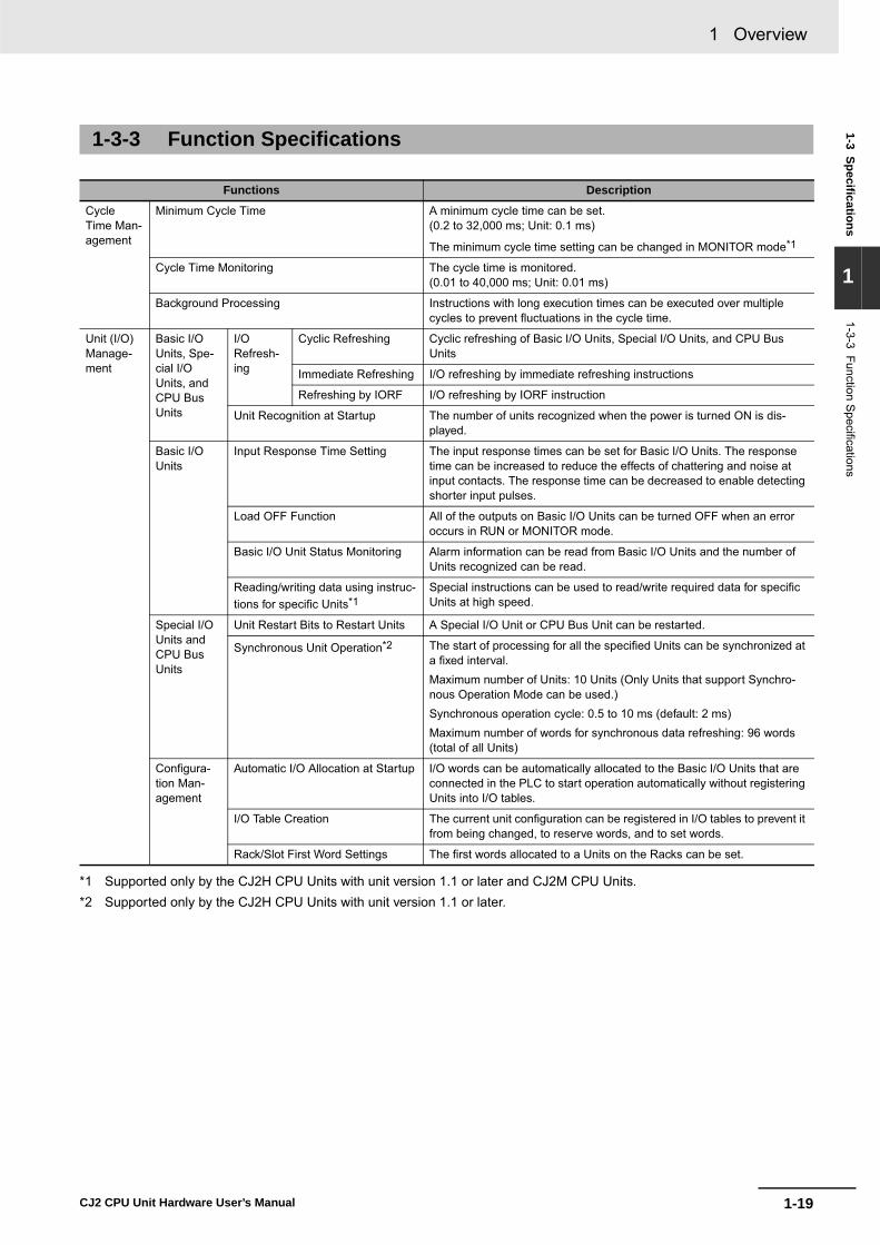
1-19
1 Overview
CJ2 CPU Unit Hardware User’s Manual
1-3 Specifications
1
1-3-3 Function Specifications
*1 Supported only by the CJ2H CPU Units with unit version 1.1 or later and CJ2M CPU Units.*2 Supported only by the CJ2H CPU Units with unit version 1.1 or later.
1-3-3 Function Specifications
Functions Description
Cycle Time Man-agement
Minimum Cycle Time A minimum cycle time can be set.(0.2 to 32,000 ms; Unit: 0.1 ms)
The minimum cycle time setting can be changed in MONITOR mode*1
Cycle Time Monitoring The cycle time is monitored. (0.01 to 40,000 ms; Unit: 0.01 ms)
Background Processing Instructions with long execution times can be executed over multiple cycles to prevent fluctuations in the cycle time.
Unit (I/O) Manage-ment
Basic I/O Units, Spe-cial I/O Units, and CPU Bus Units
I/ORefresh-ing
Cyclic Refreshing Cyclic refreshing of Basic I/O Units, Special I/O Units, and CPU Bus Units
Immediate Refreshing I/O refreshing by immediate refreshing instructions
Refreshing by IORF I/O refreshing by IORF instruction
Unit Recognition at Startup The number of units recognized when the power is turned ON is dis-played.
Basic I/O Units
Input Response Time Setting The input response times can be set for Basic I/O Units. The response time can be increased to reduce the effects of chattering and noise at input contacts. The response time can be decreased to enable detecting shorter input pulses.
Load OFF Function All of the outputs on Basic I/O Units can be turned OFF when an error occurs in RUN or MONITOR mode.
Basic I/O Unit Status Monitoring Alarm information can be read from Basic I/O Units and the number of Units recognized can be read.
Reading/writing data using instruc-tions for specific Units*1
Special instructions can be used to read/write required data for specific Units at high speed.
Special I/O Units and CPU Bus Units
Unit Restart Bits to Restart Units A Special I/O Unit or CPU Bus Unit can be restarted.
Synchronous Unit Operation*2 The start of processing for all the specified Units can be synchronized at a fixed interval. Maximum number of Units: 10 Units (Only Units that support Synchro-nous Operation Mode can be used.)Synchronous operation cycle: 0.5 to 10 ms (default: 2 ms)Maximum number of words for synchronous data refreshing: 96 words (total of all Units)
Configura-tion Man-agement
Automatic I/O Allocation at Startup I/O words can be automatically allocated to the Basic I/O Units that are connected in the PLC to start operation automatically without registering Units into I/O tables.
I/O Table Creation The current unit configuration can be registered in I/O tables to prevent it from being changed, to reserve words, and to set words.
Rack/Slot First Word Settings The first words allocated to a Units on the Racks can be set.

1 Overview
1-20 CJ2 CPU Unit Hardware User’s Manual
*3 A Serial Option Board is required to use a serial port for the CJ2M-CPU3@ CPU Unit. *4 A Serial Option Board is required to use the CJ2M-CPU3@ CPU Unit in Serial PLC Links. *5 Supported only by the CJ2H-CPU6@-EIP and CJ2M-CPU3@.
Functions Description
Memory Manage-ment
Holding I/O Memory when Changing Operat-ing Modes
The status of I/O memory can be held when the operating mode is changed or power is turned ON. The forced-set/reset status can be held when the operating mode is changed or power is turned ON.
File Memory Files (such as program files, data files, and symbol table files) can be stored in Memory Card, EM File Memory, or Comment Memory.
Built-in Flash Memory The user program and Parameter Area can be backed up to an internal flash memory when they are transferred to the CPU Unit.
EM File Function Parts of the EM Area can be treated as file memory.
Storing Comments I/O comments can be stored as symbol table files in a Memory Card, EM file memory, or comment memory.
EM Configuration EM Area can be set as trace memory or EM file memory.
Memory Cards
Automatic File Transfer at Startup A program file and parameter files can be read from a Memory Card when the power is turned ON.
Program Replacement during PLC Operation The whole user program can be read from a Memory Card to CPU Unit dur-ing operation.
Function for Reading and Writing Data from a Memory Card
Data in I/O memory in the CPU Unit can be written to a Memory Card in CSV/TXT format. Data in CSV/TXT format in the Memory Card can be read to I/O memory in the CPU Unit.
Communications ---
Peripheral (USB) Port
Peripheral Bus Bus for communications with various kinds of Support Software running on a personal computer. High-speed communications are supported.
Serial Port*3 ---
Host Link (SYSWAY) Communications Host Link commands or FINS commands placed between Host Link head-ers and terminators can be sent from a host computer or PT to read/write I/O memory, read/control the operating mode, and perform other operations for PLC.
No-protocol Communications I/O instructions for communications ports (such as TXD/RXD instructions) can be used for data transfer with peripheral devices such as bar code read-ers and printers.
NT Link Communications I/O memory in the PLC can be allocated and directly linked to various PT functions, including status control areas, status notification areas, touch switches, lamps, memory tables, and other objects.
Peripheral Bus Bus for communications with various kinds of Support Software running on a personal computer. High-speed communications are supported.
Serial Gateway This gateway enables receiving and automatically converting FINS to the CompoWay/F.
Serial PLC Links*4 Data is exchanged between CPU Units using serial ports without communi-cations programming. PTs set to the 1:N NT Link protocol can be included in the network.
EtherNet/IP Port*5 100Base-TX/10Base-TProtocols: TCP/IP, UDP, ARP, ICMP (ping only), BOOTPApplications: FINS, CIP, POP3, SMTP, SNTP, DNS (Client), FTP (Server)
CIP Communica-tions Service
Tag Data Links Programless cyclic data exchanges with the devices on the EtherNet/IP net-work.
Message Communica-tions
Any CIP commands can be received from the devices on the EtherNet/IP network.
FINS Communi-cations Service
Message Communica-tions
Any FINS commands can be transferred with the devices on the EtherNet/IP network.

1-21
1 Overview
CJ2 CPU Unit Hardware User’s Manual
1-3 Specifications
1
1-3-3 Function Specifications
*6 Supported only by the CJ2M CPU Units.*7 Supported only by the CJ2H CPU Units with unit version 1.1 or later.
Function Description
Interrupt Scheduled Interrupts A task is executed at a specified interval.
Resetting and restarting with MSKS(690)*6
When MSKS(690) is executed, the internal timer is restarted and the time to first interrupt is set to a fixed value.
Reading present value of internal timer with MSKS(690)*6
MSKS(690) can be used to read the time that has elapsed until the scheduled interrupt is started or since the previous scheduled interrupt.
Power OFF Interrupts A task can be executed when CPU Unit's power turns OFF.
I/O Interrupts A task can be executed when an input signal is input to an Interrupt Input Unit.
External Interrupts A task can be executed when interrupts are requested from a Special I/O Unit or a CPU Bus Unit.
High-speed Interrupt Function*7 Improves performance for executing interrupt tasks with certain restrictions.
Clock Clock Function Clock data is stored in memory. Accuracy (Accuracy depends on the temperature.)Ambient temperature of 55°C: −3.5 to +0.5 min error per monthAmbient temperature of 25°C: −1.5 to +1.5 min error per monthAmbient temperature of 0°C: −3 to +1 min error per month
Operation Start Time Storage The time when operating mode was last changed to RUN mode or MONITOR mode is stored.
Operation Stop Time Storage The last time a fatal error occurred or the last time the operating mode was changed to PROGRAM mode is stored.
Startup Time Storage The time when the power was turned ON is stored.
Power Interruption Time Storage The time when the power is turned OFF is stored.
Total Power ON Time Calculation The total time that the PLC has been ON is stored in increments of 10 hours.
Power ON Clock Data Storage A history of the times when the power was turned ON is stored.
User Program Overwritten Time Storage The time that the user program was last overwritten is stored.
Parameter Date Storage The time when the Parameter Area was overwritten is stored.

1 Overview
1-22 CJ2 CPU Unit Hardware User’s Manual
Function Description
Power Supply Manage-ment
Memory Protection Holding Area data, DM Area data, EM Area data, Counter Completion Flags, and counter present values are held even when power is turned OFF. CIO Area, Work Area, some Auxiliary Area data, and Timer Completion Flags, timer present values, index registers, and data registers can be protected by turning ON the IOM Hold Bit in the Auxiliary Area, and by also setting the IOM Hold Bit to “Hold” in the PLC Setup.
Power OFF Detection Time Setting The detection time for power interruptions can be set. AC power supply: 10 to 25 ms (variable)DC power supply: 2 to 5 ms (CJ1W-PD022) or 2 to 20 ms (CJ1W-PD025)
Power OFF Detection Delay Time The detection of power interruptions can be delayed: 0 to 10 ms(Not supported by the CJ1W-PD022.)
Number of Power Interruptions Counter The number of times power has been interrupted is counted.
Function Blocks Standard programming can be encapsulated as function blocks.
Languages in Function Block Definitions Ladder programming or structured text
Debug-ging
Online Editing The program can be changed during operation (in MONITOR or PROGRAM mode), except for block programming areas.
Force-Set/Reset Specified bits can be set or reset. A parameter can be set to enable force-setting/resetting bits in EM Area banks. Force-setting/resetting is enabled for the specified bank and all the banks after it.*9
Differentiate Monitoring ON/OFF changes in specified bits can be monitored.
Data Tracing The specified I/O memory data can be stored in the trace memory in the CPU Unit. The triggers can be set.
Continuous Tracing The trace data can be uploaded during data tracing using the CX-Programmer. This enables continuously logging the data by constantly uploading the trace data.
Automatically starting tracing when opera-tion starts
Data tracing can be automatically started when operation is started (i.e., when the operating mode is changed from PROGRAM mode to MONITOR or RUN mode).
Storing Location of Error when an Error Occurs
The location and task number where execution stopped for a program error is recorded.
Program Check The programs can be checked for items such as no END instruction and FALS/FAL errors at startup.
Self-diag-nosis and Restora-tion
Error Log A function is provided to store predefined error codes in CPU Unit, error infor-mation, and time at which the error occurred.
CPU Error Detection CPU Unit WDT errors are detected.
User-defined Failure Diagnosis Errors can be generated for user-specified conditions: Non-fatal errors (FAL) and fatal errors (FALS). Program section time diagnosis and program section logic diagnosis are sup-ported (FPD instruction).
Load OFF Function This function turns OFF all outputs from Output Units when an error occurs.
RUN Output The RUN output from the CJ1W-PA205R turns ON while CPU Unit is in RUN mode or MONITOR mode.
Basic I/O Load Short-circuit Detection This function provides alarm information from Basic I/O Units that have load short-circuit protection.
Failure Point Detection The time and logic of an instruction block can be analyzes using the FPD instruction.
CPU Standby Detection This function indicates when the CPU Unit is on standby because all Special I/O Units and CPU Bus Units have not been recognized at the startup in RUN or MONITOR mode.
*8 Supported only by the CJ2H CPU Units with unit version 1.2 or later and CJ2M CPU Units.

1-23
1 Overview
CJ2 CPU Unit Hardware User’s Manual
1-3 Specifications
1
1-3-3 Function Specifications
*9 Supported only by the CJ2H-CPU6@-EIP and CJ2M-CPU3@.*10 Supported only by the CJ2M-CPU3@.
Function Description
Self-diag-nosis and Restora-tion(Contin-ued from previous page)
Non-fatal Error Detection
System FAL Error Detec-tion (User-defined non-fatal error)
This function generates a non-fatal (FAL) error when the user-defined condi-tions are met in program.
Duplicated Refreshing Error Detection
This function detects an error when an immediate refreshing Instruction in an interrupt task is competing with I/O refreshing of a cyclic task.
Basic I/O Unit Error Detec-tion
This function detects the errors in Basic I/O Units.
Backup Memory Error Detection
This function detects errors in the memory backup of the user programs and parameter area (backup memory).
PLC Setup Error Detection This function detects setting errors in the PLC Setup.
CPU Bus Unit Error Detec-tion
This function detects an error when there is an error in data exchange between the CPU Unit and a CPU Bus Unit.
Special I/O Unit Error Detection
This function detects an error when there is an error in data exchange between the CPU Unit and a Special I/O Unit.
Tag Memory Error Detec-tion*10
This function detects errors in tag memory.
Battery Error Detection This function detects an error when a battery is not connected to the CPU Unit or when the battery voltage drops.
CPU Bus Unit Setting Error Detection
This function detects an error when the model of a CPU Bus Unit in the regis-tered I/O tables does not agree with the model that is actually mounted in the PLC.
Special I/O Unit Setting Error Detection
This function detects an error when the model of a Special I/O Unit in the regis-tered I/O tables does not agree with the model of Unit that is actually mounted.
Option Board Error Detec-tion*11
This function detects the errors in Serial Option Board mounting status.
Fatal Error Detection
Memory Error Detection This function detects errors that occur in memory of the CPU Unit.
I/O Bus Error Detection This function detects when an error occurs in data transfers between the Units mounted in Rack slots and the CPU Unit and detects when the End Cover is not connected to the CPU Rack or an Expansion Rack.
Unit/Rack Number Dupli-cation Error
This function detects an error when the same unit number is set for two or more Units, the same word is allocated to two or more Basic I/O Units, or the same rack number is set for two or more Racks.
Too Many I/O Points Error Detection
This function detects an error when the total number of I/O points set in the I/O tables or the number of Units per Rack exceeds the specified range.
I/O Setting Error Detection The registered I/O tables are used to detect errors if the number of Units in the registered I/O tables does not agree with the actual number of Units that are connected or an Interrupt Unit has been connected in the wrong position.

1 Overview
1-24 CJ2 CPU Unit Hardware User’s Manual
*11 This function can be used only with CJ2H CPU Units.
Function Description
Self-diag-nosis and Restora-tion(Contin-ued from previous page)
Fatal Error Detection
Program Error Detection This function detects errors in programs.
Instruction Processing Error Detection
This function detects an error when the given data value is invalid when execut-ing an instruction, or execution of instruction between tasks was attempted.
Indirect DM/EM BCD Error Detection
This function detects an error when an indirect DM/EM address in BCD mode is not BCD.
Illegal Area Access Error Detection
This function detects an error when an attempt is made to access an illegal area with an instruction operand.
No END Error Detec-tion
This function detects an error when there is no END instruction at the end of the program.
Task Error Detection This function detects an error when there are no tasks that can be executed in a cycle, there is no program for a task, or the execution condition for an inter-rupt task was met but there is no interrupt task with the specified number.
Differentiation Over-flow Error Detection
This function detects an error when too many differentiated instructions are entered or deleted during online editing (131,072 times or more).
Invalid Instruction Error Detection
This function detects an error when an attempt is made to execute an instruc-tion that is not defined in the system.
User Program Area Overflow Error Detec-tion
This function detects an error when instruction data is stored after the last address in user program area.
Cycle Time Exceeded Error Detection
This function monitors the cycle time (10 to 40,000 ms) and stops the operation when the set value is exceeded.
System FALS Error Detec-tion (User-defined Fatal Error)
This function generates a fatal (FALS) error when the user-defined conditions are met in program.
Version Error Detection This function detects an error when a user program includes a function that is not supported by the current unit version.
Memory Card Transfer Error Detection
This function detects an error when the automatic file transfer from Memory Card fails at startup.
Memory Self-restoration Function This function performs a parity check on the user program area and self-resto-ration data.*12
Mainte-nance
Simple Backup Function This function collectively backs up the data in CPU Unit (user programs, parameters, and I/O memory) and internal backup data in the I/O Units.
Unsolicited Communications A function that allows the PLC to use Network Communications Instruction to send required FINS commands to a computer connected via a Host Link
Remote Programming and Monitoring Host Link communications can be used for remote programming and remote monitoring through a Controller Link, Ethernet, DeviceNet, or SYSMAC LINK Network. Communications across network layers can be performed.Controller Link or Ethernet: 8 layersDeviceNet or SYSMAC LINK: 3 layers
Automatic Online Connection via Network
Direct Serial Connec-tion
This function enables automatically connecting to the PLC online when the CX-Programmer is directly connected by a serial connection (peripheral (USB) port or serial port).
Via Net-works
This function enables connecting the CX-Programmer online to a PLC that is connected via an EtherNet/IP network.
Security Read Protection using Password This function protects reading and displaying programs and tasks using pass-words.Write protection: Set using the DIP switch.Read protection: Set a password using the CX-Programmer.
FINS Write Protection This function prohibits writing by using FINS commands sent over the network.
Unit Name Function This function allows the users to give any names to the Units. Names are veri-fied at online connection to prevent wrong connection
Hardware ID Using Lot Numbers This function sets operation protection by identifying hardware using the user programs according to lot numbers stored in the Auxiliary Area.

2-1CJ2 CPU Unit Hardware User’s Manual
2
This section describes the basic system configuration and devices used in a CJ2 PLC.
The CJ Series supports the following two types of system configuration.
• Basic System Configuration: System consisting of CPU Rack and Expansion Racks.
• Expanded System Configuration: System connected via CPU Unit built-in serial port and PLC Units, such as Communi-cations Units.
2-1 Basic System Configuration . . . . . . . . . . . . . . . . . . . . . . . . . . . . . . . . . . . . . 2-22-1-1 Basic System Configuration . . . . . . . . . . . . . . . . . . . . . . . . . . . . . . . . . . . . . . . 2-22-1-2 CPU Rack . . . . . . . . . . . . . . . . . . . . . . . . . . . . . . . . . . . . . . . . . . . . . . . . . . . . 2-32-1-3 Expansion Racks . . . . . . . . . . . . . . . . . . . . . . . . . . . . . . . . . . . . . . . . . . . . . . 2-102-1-4 Configuration Units . . . . . . . . . . . . . . . . . . . . . . . . . . . . . . . . . . . . . . . . . . . . 2-132-1-5 Calculating Unit Current Consumption . . . . . . . . . . . . . . . . . . . . . . . . . . . . . 2-212-1-6 Calculating Power Consumption . . . . . . . . . . . . . . . . . . . . . . . . . . . . . . . . . . 2-24
2-2 Expanded System Configuration . . . . . . . . . . . . . . . . . . . . . . . . . . . . . . . . 2-262-2-1 Serial Communications . . . . . . . . . . . . . . . . . . . . . . . . . . . . . . . . . . . . . . . . . 2-262-2-2 Communications Networks . . . . . . . . . . . . . . . . . . . . . . . . . . . . . . . . . . . . . . 2-28
Basic System Configuration and Devices

2 Basic System Configuration and Devices
2-2 CJ2 CPU Unit Hardware User’s Manual
2-1 Basic System Configuration
� CPU RackA CPU Rack can consist of a CJ2 CPU Unit, a CJ-series Power Supply Unit, CJ-series ConfigurationUnits (Basic I/O Units, Special I/O Units, CPU Bus Units), and a CJ-series End Cover. The same CJ-series Power Supply Units and CJ-series Configuration Units that are used with CJ1 CPU Units areused with CJ2 CPU Units.* An I/O Control Unit is required to connect a CJ-series Expansion Rack.A Memory Card is optional.
* All CJ-series Units can be used as Configuration Units, but only Units that specifically support the CJ2 CPU Unitcan access the expanded portions of the I/O memory areas of the CJ2 CPU Units (i.e., A960 to A1471, A10000to A11535, and EM banks D to 18). Only the following CJ1 Units specifically support the CJ2 CPU Units.
• EtherNet/IP Unit: CJ1W-EIP21• Position Control Units: CJ1W-NC214, CJ1W-NC234, CJ1W-NC281, CJ1W-NC414, CJ1W-NC434, CJ1W-
NC481, and CJ1W-NC881• Analog Input Unit: CJ1W-AD042• Analog Output Unit: CJ1W-DA042V• Serial Communications Units: CJ1W-SCU22, CJ1W-SCU32, and CJ1W-SCU42
� Expansion RacksA CJ-series Expansion Rack can be connected to the CPU Rack or another CJ-series ExpansionRack. An Expansion Rack can consist of an I/O Interface Unit, a Power Supply Unit, Basic I/O Units,Special I/O Units, CPU Bus Units, and an End Cover.
2-1-1 Basic System Configuration
CPU RackPower Supply Unit CPU Unit I/O Control Unit
Configuration Units(Basic I/O Units, SpecialI/O Units, CPU Bus Units)
Configuration Units(Basic I/O Units, SpecialI/O Units, CPU Bus Units)
Expansion RackPower Supply Unit I/O Interface Unit
End Cover
End CoverMemory Card

2-3
2 Basic System Configuration and Devices
CJ2 CPU Unit Hardware User’s Manual
2-1 Basic System
Configuration
2
2-1-2 CP
U R
ack
The CPU Rack consists of a CJ2 CPU Unit, a CJ-series Power Supply Unit, CJ-series ConfigurationUnits, and a CJ-series End Cover. Up to 10 Configuration Units can be connected.
� CJ2H CPU Units
*1 The I/O Control Unit is required only to connect an Expansion Rack. It must be connected next to the CPUUnit.
� CJ2M CPU Units
2-1-2 CPU Rack
Memory Card
Configuration Units (10 max.)(Basic I/O Units, Special I/O Units, CPU Bus Units)
POWER
PA205R
DC24VAC240VOUTPUT
RUN
INPUTAC100-240V
L2/N
L1
CONTROLLERPROGRAMMABLE
ERR/ALMRUN
COMMBKUP
INHPRPHL
OPEN
PERIPHERAL
BUSY
MCPWR
PORT
CJ2HCPU64-EIP
SYSMAC NSMS
100M10M
COMM
CPU UnitPower Supply Unit End Cover
I/O Control Unit*1
POWER
PA205R
DC24VAC240VOUTPUT
RUN
INPUTAC100-240V
L2/N
L1
Power Supply Unit CPU Unit
Memory Card
Configuration Units (10 max.)
End CoverI/O Control Unit*2
Serial Option Board*1
RS-232C RS-422A/485
*1 CJ2M-CPU3@ only.*2 The I/O Control Unit is required only
to connect an Expansion Rack. It must be connected immediately to the right of the CPU Unit.

2 Basic System Configuration and Devices
2-4 CJ2 CPU Unit Hardware User’s Manual
Although the CJ-series PLCs do not require Backplanes, the term “slot” is still used to refer to the rela-tive position of a Unit in the Rack. Slot numbers increase toward the right side of the Rack.
Name Configuration RemarksCJ-series CPU Rack
CPU Unit CJ2H CPU Units One required for every CPU Rack.
CJ2M CPU Units One required for every CPU Rack.
Serial Option Board (Can be mounted only with the CJ2M-CPU3@.)
One Serial Option Board can be mounted in the CJ2M-CPU3@.
Memory Card Install as required.
CJ-series Power Supply Unit One required for every CPU Rack.
I/O Control Unit Required to connect an Expansion Rack. Must be connected immediately to the right of the CPU Unit.
Configu-ration Units
CJ-series Basic I/O Units
A total of up to 10 Units can be connected to the CPU Rack and to each of the Expansion Racks. (An error will occur if 11 or more Units are connected.)CJ-series Special
I/O Units
CJ-series CPU Bus Units
EndCover
Must be connected to the right end of the CPU Rack. One End Cover is provided with the CPU Unit.A fatal error will occur if the End Cover is not connected.

2-5
2 Basic System Configuration and Devices
CJ2 CPU Unit Hardware User’s Manual
2-1 Basic System
Configuration
2
2-1-2 CP
U R
ack
� CJ2H CPU Units
*1 Increases by 0.15 A/Unit when an NT-AL001 Link Adapter is used.Increases by 0.04 A/Unit when a CJ1W-CIF11 RS-422A Converter is used.Increases by 0.20 A/Unit when an NV3W-M@20L Programmable Terminal is used.
*2 Includes the weight of the End Cover.
Units
Model I/O capacity Program capacity DM Area capacity
Current consumption (A) Weight
5 VDC 24 VDCCJ2H-CPU68-EIP 2,560 points 400 Ksteps 832 Kwords
(DM: 32 Kwords, EM: 32 Kwords × 25 banks)
0.82*1 --- 280 g max.*2
CJ2H-CPU67-EIP 250 Ksteps 512 Kwords (DM: 32 Kwords, EM: 32 Kwords × 15 banks)
CJ2H-CPU66-EIP 150 Ksteps 352 Kwords (DM: 32 Kwords, EM: 32 Kwords × 10 banks)
CJ2H-CPU65-EIP 100 Ksteps 160 Kwords (DM: 32 Kwords, EM: 32 Kwords × 4 banks)
CJ2H-CPU64-EIP 50 Ksteps 160 Kwords (DM: 32 Kwords, EM: 32 Kwords × 4 banks)
CJ2H-CPU68 2,560 points 400 Ksteps 832 Kwords (DM: 32 Kwords, EM: 32 Kwords × 25 banks)
0.42*1 --- 190 g max.*2
CJ2H-CPU67 250 Ksteps 512 Kwords (DM: 32 Kwords, EM: 32 Kwords × 15 banks)
CJ2H-CPU66 150 Ksteps 352 Kwords (DM: 32 Kwords, EM: 32 Kwords × 10 banks)
CJ2H-CPU65 100 Ksteps 160 Kwords (DM: 32 Kwords, EM: 32 Kwords × 4 banks)
CJ2H-CPU64 50 Ksteps 160 Kwords (DM: 32 Kwords, EM: 32 Kwords × 4 banks)
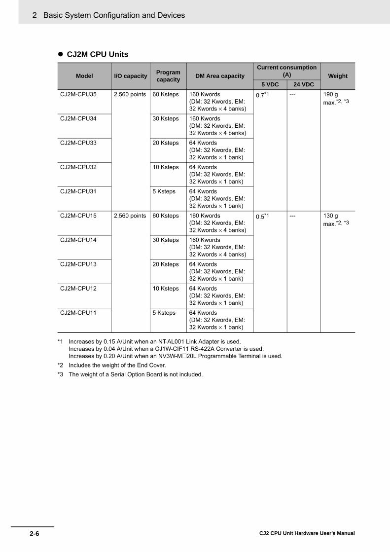
2 Basic System Configuration and Devices
2-6 CJ2 CPU Unit Hardware User’s Manual
� CJ2M CPU Units
*1 Increases by 0.15 A/Unit when an NT-AL001 Link Adapter is used.Increases by 0.04 A/Unit when a CJ1W-CIF11 RS-422A Converter is used.Increases by 0.20 A/Unit when an NV3W-M@20L Programmable Terminal is used.
*2 Includes the weight of the End Cover.*3 The weight of a Serial Option Board is not included.
Model I/O capacity Program capacity DM Area capacity
Current consumption (A) Weight
5 VDC 24 VDCCJ2M-CPU35 2,560 points 60 Ksteps 160 Kwords
(DM: 32 Kwords, EM: 32 Kwords × 4 banks)
0.7*1 --- 190 g max.*2, *3
CJ2M-CPU34 30 Ksteps 160 Kwords (DM: 32 Kwords, EM: 32 Kwords × 4 banks)
CJ2M-CPU33 20 Ksteps 64 Kwords (DM: 32 Kwords, EM: 32 Kwords × 1 bank)
CJ2M-CPU32 10 Ksteps 64 Kwords (DM: 32 Kwords, EM: 32 Kwords × 1 bank)
CJ2M-CPU31 5 Ksteps 64 Kwords (DM: 32 Kwords, EM: 32 Kwords × 1 bank)
CJ2M-CPU15 2,560 points 60 Ksteps 160 Kwords (DM: 32 Kwords, EM: 32 Kwords × 4 banks)
0.5*1 --- 130 g max.*2, *3
CJ2M-CPU14 30 Ksteps 160 Kwords (DM: 32 Kwords, EM: 32 Kwords × 4 banks)
CJ2M-CPU13 20 Ksteps 64 Kwords (DM: 32 Kwords, EM: 32 Kwords × 1 bank)
CJ2M-CPU12 10 Ksteps 64 Kwords (DM: 32 Kwords, EM: 32 Kwords × 1 bank)
CJ2M-CPU11 5 Ksteps 64 Kwords (DM: 32 Kwords, EM: 32 Kwords × 1 bank)
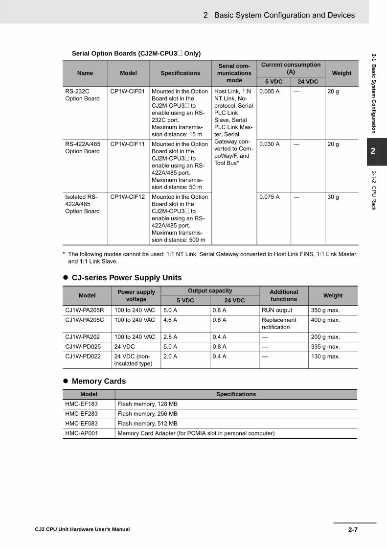
2-7
2 Basic System Configuration and Devices
CJ2 CPU Unit Hardware User’s Manual
2-1 Basic System
Configuration
2
2-1-2 CP
U R
ack
Serial Option Boards (CJ2M-CPU3@ Only)
* The following modes cannot be used: 1:1 NT Link, Serial Gateway converted to Host Link FINS, 1:1 Link Master,and 1:1 Link Slave.
� CJ-series Power Supply Units
� Memory Cards
Name Model SpecificationsSerial com-munications
mode
Current consumption (A) Weight
5 VDC 24 VDCRS-232C Option Board
CP1W-CIF01 Mounted in the Option Board slot in the CJ2M-CPU3@ to enable using an RS-232C port. Maximum transmis-sion distance: 15 m
Host Link, 1:N NT Link, No-protocol, Serial PLC Link Slave, Serial PLC Link Mas-ter, Serial Gateway con-verted to Com-poWay/F, and Tool Bus*
0.005 A --- 20 g
RS-422A/485 Option Board
CP1W-CIF11 Mounted in the Option Board slot in the CJ2M-CPU3@ to enable using an RS-422A/485 port. Maximum transmis-sion distance: 50 m
0.030 A --- 20 g
Isolated RS-422A/485 Option Board
CP1W-CIF12 Mounted in the Option Board slot in the CJ2M-CPU3@ to enable using an RS-422A/485 port. Maximum transmis-sion distance: 500 m
0.075 A --- 30 g
Model Power supply voltage
Output capacity Additional functions Weight
5 VDC 24 VDCCJ1W-PA205R 100 to 240 VAC 5.0 A 0.8 A RUN output 350 g max.
CJ1W-PA205C 100 to 240 VAC 4.6 A 0.8 A Replacement notification
400 g max.
CJ1W-PA202 100 to 240 VAC 2.8 A 0.4 A --- 200 g max.
CJ1W-PD025 24 VDC 5.0 A 0.8 A --- 335 g max.
CJ1W-PD022 24 VDC (non-insulated type)
2.0 A 0.4 A --- 130 g max.
Model SpecificationsHMC-EF183 Flash memory, 128 MB
HMC-EF283 Flash memory, 256 MB
HMC-EF583 Flash memory, 512 MB
HMC-AP001 Memory Card Adapter (for PCMIA slot in personal computer)
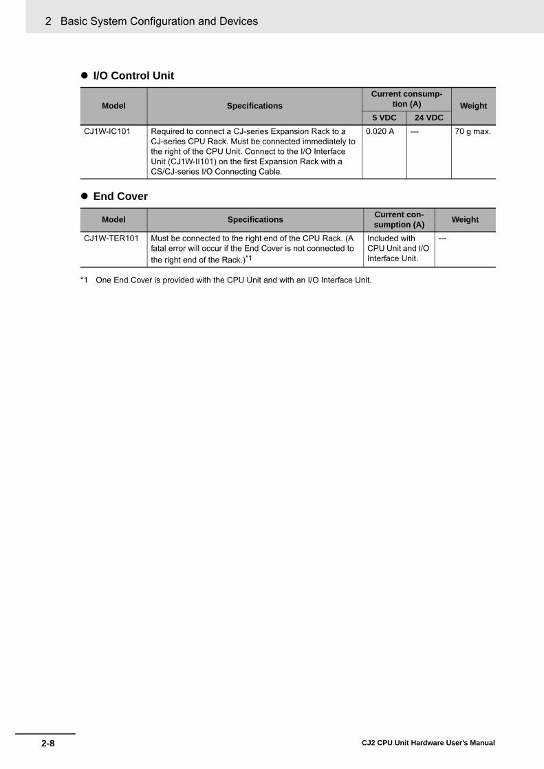
2 Basic System Configuration and Devices
2-8 CJ2 CPU Unit Hardware User’s Manual
� I/O Control Unit
� End Cover
*1 One End Cover is provided with the CPU Unit and with an I/O Interface Unit.
Model SpecificationsCurrent consump-
tion (A) Weight5 VDC 24 VDC
CJ1W-IC101 Required to connect a CJ-series Expansion Rack to a CJ-series CPU Rack. Must be connected immediately to the right of the CPU Unit. Connect to the I/O Interface Unit (CJ1W-II101) on the first Expansion Rack with a CS/CJ-series I/O Connecting Cable.
0.020 A --- 70 g max.
Model Specifications Current con-sumption (A) Weight
CJ1W-TER101 Must be connected to the right end of the CPU Rack. (A fatal error will occur if the End Cover is not connected to the right end of the Rack.)*1
Included with CPU Unit and I/O Interface Unit.
---

2-9
2 Basic System Configuration and Devices
CJ2 CPU Unit Hardware User’s Manual
2-1 Basic System
Configuration
2
2-1-2 CP
U R
ack
* CJ2H-CPU6@-EIP or CJ2M-CPU3@ only.
Others
Name Model SpecificationsDIN Track PFP-50N Track length: 50 cm, height: 7.3 mm
PFP-100N Track length: 1 m, height: 7.3 mm
PFP-100N2 Track length: 1 m, height: 16 mm
PFP-M Stopper to prevent Units from moving on the track.Two each are provided with the CPU Unit and with an I/O Interface Unit.
Programming Device Connecting Cable for peripheral (USB) port
Commercially avail-able USB cable
USB 2.0 (or 1.1) cable (A connector - B connec-tor), 5.0 m max.
Programming Device Connecting Cables for serial port
XW2Z-200S-CV Connects to IBM PC/AT computerD-Sub 9-pin connector (Cable length: 2.0 m).Uses static-resistant connector.
XW2Z-500S-CV Connects to IBM PC/AT computerD-Sub 9-pin connector (Cable length: 5.0 m).Uses static-resistant connector.
XW2Z-200S-V Connects to IBM PC/AT computer
D-Sub 9-pin connector. (Cable length: 2.0 m)
XW2Z-500S-V Connects to IBM PC/AT computer
D-Sub 9-pin connector. (Cable length: 5.0 m)
Connecting Cable for EtherNet/IP port*
Commercially avail-able 100Base-TX twisted-pair cable
Recommended: Fujikura F-LINK-E 0.5 mm × 4PTwisted-pair cable with RJ45 Modular Connectors on both ends. Connect between EtherNet/IP Unit or built-in EtherNet/IP port and switching hub. Use STP (shielded twisted-pair) cable of category 5 or 5e.
Communications Adaptor (RS-422A Converter)
CJ1W-CIF11 Current consumption at 5 V: 0.04 A
RS-232C/RS-422A Link Adapter NT-AL001 Maximum distance: 500 m; only RS-422A is sup-ported. Current consumption at 5 V: 0.15 A
Battery Set CJ1W-BAT01 For CJ2 CPU Unit
Support Software CX-One CXONE-AL@@C-V@/CXONE-AL@@D-V@
CX-One is an FA Integrated Tool Package that integrates the PLC, network, HMI, components, motion control, and PLC-based process control.• CX-Programmer• CX-Integrator• SwitchBox Utility• CX-Simulator• CX-Protocol• CX-Designer• CX-Thermo• CX-Position• CX-Motion/CX-Motion-NCF/CX-Motion-MCH• CX-Drive • CX-Process Tool• NS Faceplate Auto-Builder• CX-FLnet• Network Configurator

2 Basic System Configuration and Devices
2-10 CJ2 CPU Unit Hardware User’s Manual
CJ-series Expansion Racks can be connected to the CPU Rack to expand the number of Units in theSystem beyond the CPU Rack. Up to 10 I/O Units can be mounted to each Expansion Rack and a totalof 3 Expansion Racks can be connected.
Mount an I/O Control Unit immediately to the right of the CPU Unit, and mount the I/O Interface Unitimmediately to the right of the Power Supply Unit on the Expansion Rack. Mounting them in other loca-tions may cause malfunctions.
2-1-3 Expansion Racks
CPU Rack (Except for CPU Units for 2-slot Racks)
CS/CJ-series I/O Connecting Cables CableCS1W-CN313CS1W-CN713CS1W-CN223CS1W-CN323CS1W-CN523CS1W-CN133CS1W-CN133B2
Length0.3 m0.7 m2 m3 m5 m10 m12 m
CJ-series Expansion Rack
CS/CJ-series I/O Connecting Cable30 cm, 70 cm, 2 m, 3 m, 5 m, 10 m, 12 m
ExpansionRacks:3 maximum
Total cablelength:12 m
End Cover
I/O Control Unit
I/O Interface UnitI/O Interface Unit
10 Units max.
PowerSupplyUnit
PowerSupplyUnit
PowerSupplyUnit
CJ-series Expansion Rack
CS/CJ-series I/O Connecting Cable30 cm, 70 cm, 2 m, 3 m, 5 m, 10 m, 12 m
CPUUnit
10 Units max.
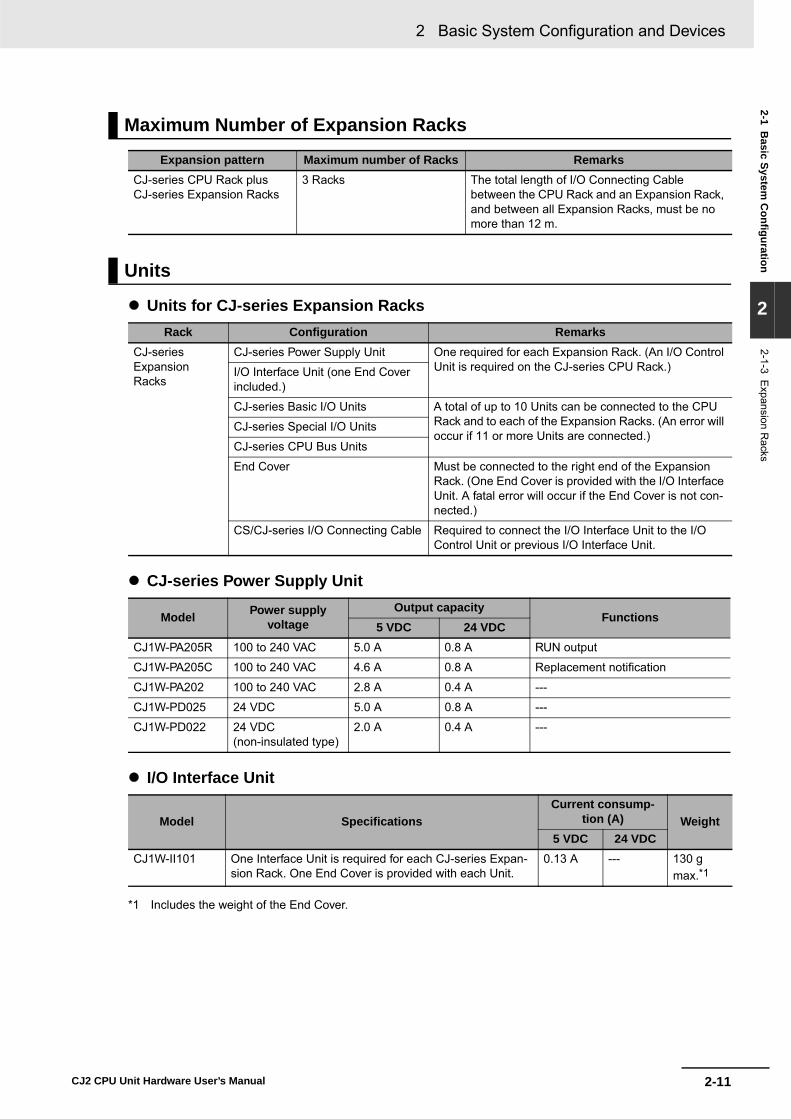
2-11
2 Basic System Configuration and Devices
CJ2 CPU Unit Hardware User’s Manual
2-1 Basic System
Configuration
2
2-1-3 Expansion R
acks
� Units for CJ-series Expansion Racks
� CJ-series Power Supply Unit
� I/O Interface Unit
*1 Includes the weight of the End Cover.
Maximum Number of Expansion Racks
Expansion pattern Maximum number of Racks RemarksCJ-series CPU Rack plus CJ-series Expansion Racks
3 Racks The total length of I/O Connecting Cable between the CPU Rack and an Expansion Rack, and between all Expansion Racks, must be no more than 12 m.
Units
Rack Configuration RemarksCJ-series Expansion Racks
CJ-series Power Supply Unit One required for each Expansion Rack. (An I/O Control Unit is required on the CJ-series CPU Rack.)I/O Interface Unit (one End Cover
included.)
CJ-series Basic I/O Units A total of up to 10 Units can be connected to the CPU Rack and to each of the Expansion Racks. (An error will occur if 11 or more Units are connected.)
CJ-series Special I/O Units
CJ-series CPU Bus Units
End Cover Must be connected to the right end of the Expansion Rack. (One End Cover is provided with the I/O Interface Unit. A fatal error will occur if the End Cover is not con-nected.)
CS/CJ-series I/O Connecting Cable Required to connect the I/O Interface Unit to the I/O Control Unit or previous I/O Interface Unit.
Model Power supply voltage
Output capacityFunctions
5 VDC 24 VDCCJ1W-PA205R 100 to 240 VAC 5.0 A 0.8 A RUN output
CJ1W-PA205C 100 to 240 VAC 4.6 A 0.8 A Replacement notification
CJ1W-PA202 100 to 240 VAC 2.8 A 0.4 A ---
CJ1W-PD025 24 VDC 5.0 A 0.8 A ---
CJ1W-PD022 24 VDC (non-insulated type)
2.0 A 0.4 A ---
Model SpecificationsCurrent consump-
tion (A) Weight5 VDC 24 VDC
CJ1W-II101 One Interface Unit is required for each CJ-series Expan-sion Rack. One End Cover is provided with each Unit.
0.13 A --- 130 g max.*1

2 Basic System Configuration and Devices
2-12 CJ2 CPU Unit Hardware User’s Manual
� End Cover
� CS/CJ-series I/O Connecting Cables
Model Specifications Current con-sumption (A) Weight
CJ1W-TER01 Must be connected to the right end of the CPU Rack. (A fatal error will occur if the End Cover is not connected to the right end of the Rack.)One End Cover is provided with the CPU Unit and with an I/O Interface Unit.
Included with the CPU Unit or I/O Interface Unit.
---
Model Specifications Cable lengthCS1W-CN313 An I/O Connecting Cable connects an I/O Control Unit (CJ1W-IC101) to an
I/O Interface Unit (CJ1W-II101), or connects an I/O Interface Unit to another I/O Interface Unit.
0.3 m
CS1W-CN713 0.7 m
CS1W-CN223 2 m
CS1W-CN323 3 m
CS1W-CN523 5 m
CS1W-CN133 10 m
CS1W-CN133B2 12 m

2-13
2 Basic System Configuration and Devices
CJ2 CPU Unit Hardware User’s Manual
2-1 Basic System
Configuration
2
2-1-4 Configuration U
nits
A maximum of 10 Units can be connected to the CPU Rack for a CJ2 CPU Unit or to an ExpansionRack. There are no restrictions in the number of each model of Unit based on location.
Note A fatal error will occur and the CPU Unit will not operate if more than the allowable number of Units is con-nected to a CJ2 CPU Rack or to an Expansion Rack.
The Configuration Units with which the CJ2 CPU Unit can exchange data are classified into threegroups. The number of Units that can be mounted depends on the type of Unit.
2-1-4 Configuration Units
Maximum Number of Units
Models of Configuration Units
Units Description Unit identifica-tion method
Number of mountable Units
Basic I/O Units Basic I/O Units are used for discrete inputs and outputs.
Identified by the CPU Unit accord-ing to mounting position.
No limit
Special I/O Units Special I/O Units are more advanced than Basic I/O Units. They support functions other than dis-crete inputs and outputs.Examples: Analog I/O Units and High-speed Counter UnitsSpecial I/O Units have a smaller area for exchanging data with the CPU Unit than CPU Bus Units (including Network Communications Units).
Identified by the CPU Unit using unit numbers 0 to 95 set with the rotary switches on the front panel of the Unit.
Up to 96 Special I/O Units can be mounted.(Depending on the model, 1 to 4 unit numbers are used for one Unit.)
CPU Bus Unit CPU Units are advanced units that exchange data with the CPU Unit via the CPU bus.Examples: Network Communications Units and Serial Com-munications UnitsCPU Bus Units have a larger area for exchang-ing data with the CPU Unit than Special I/O Units.
Identified by the CPU Unit using unit number 0 to F set with the rotary switch on the front panel of the Unit.
Up to 15 CPU Bus Units can be mounted.

2 Basic System Configuration and Devices
2-14 CJ2 CPU Unit Hardware User’s Manual
� CJ-series Basic I/O UnitsInput Units
*1 Although 16 I/O bits are allocated, only 8 of these can be used for external I/O. This Unit is also treated as a16-point I/O Unit in the I/O tables.
*2 The ON/OFF response time for the CJ1W-ID212/CJ1W-ID233 is shorter than for the CJ1W-ID211/CJ1W-ID232, as shown below.
• ON response time: 20 μs improved to 15 μs• OFF response time: 400 μs improved to 90 μs
*3 The cable-side connector is not provided with Units equipped with cables. Purchase the connector separately(Refer to 5-3-3 Wiring Basic I/O Units with Connectors.), or use an OMRON Connector- Terminal Block Con-version Unit or I/O Terminal (Refer to 5-3-4 Connecting to Connector-Terminal Block Conversion Units or I/ORelay Terminals.).
*4 An Interrupt Input Unit can be connected only in a CJ-series CPU Rack. Connect the Interrupt Input Units infollowing slots on the CPU Rack. An I/O setting error will occur if an Interrupt Input Unit is connected in otherpositions on the CPU Rack or to any position on an Expansion Rack. Up to two Interrupt Input Units can beconnected.
• CJ2H-CPU6@-EIP: Slots 0 to 3 • CJ2H-CPU6@ or CJ2M-CPU@@: Slots 0 to 4
Configuration Units
Name Specifications ModelNumber of bits allo-
cated
Current consumption (A) Weight
5 VDC 24 VDCDC Input Units
Terminal block 12 to 24 VDC, 8 inputs
CJ1W-ID201 16*1 0.08 --- 110 g max.
Terminal block 24 VDC, 16 inputs
CJ1W-ID211*2 16 0.08 --- 110 g max.
CJ1W-ID212*2 16 0.13 --- 110 g max.
Fujitsu-compatible con-nector24 VDC, 32 inputs
CJ1W-ID231*3 32 0.09 --- 70 g max.
MIL connector24 VDC, 32 inputs
CJ1W-ID232*2*3
32 0.09 --- 70 g max.
CJ1W-ID233*2*3
32 0.20 --- 70 g max.
Fujitsu-compatible con-nector24 VDC, 64 inputs
CJ1W-ID261*3 64 0.09 --- 110 g max.
MIL connector24 VDC, 64 inputs
CJ1W-ID262*3 64 0.09 --- 110 g max.
AC Input Units
200 to 240 VAC, 8 inputs
CJ1W-IA201 16*1 0.08 --- 130 g max.
100 to 120 VAC, 16 inputs
CJ1W-IA111 16 0.09 --- 130 g max.
Interrupt Input Units
24 VDC, 16 inputs CJ1W-INT01*4 16 0.08 --- 110 g max.
Quick-responseInput Units
24 VDC, 16 inputs CJ1W-IDP01 16 0.08 --- 110 g max.
B7A Interface Units
64 inputs CJ1W-B7A14 64 0.09 --- 80 g max.

2-15
2 Basic System Configuration and Devices
CJ2 CPU Unit Hardware User’s Manual
2-1 Basic System
Configuration
2
2-1-4 Configuration U
nits
Output Units
*1 Although 16 I/O bits are allocated, only 8 of these can be used for external I/O. This Unit is also treated as a16-point I/O Unit in the I/O tables.
*2 The ON/OFF response time for the CJ1W-OD213/CJ1W-OD234 is shorter than for the CJ1W-OD211/CJ1W-OD233, as shown below.
• ON response time: 0.1 ms improved to 0.015 ms • OFF response time: 0.8 ms improved to 0.08 ms
*3 The cable-side connector is not provided with Units equipped with cables. Purchase the connector separately(Refer to 5-3-3 Wiring Basic I/O Units with Connectors.), or use an OMRON Connector- Terminal Block Con-version Unit or I/O Terminal (Refer to 5-3-4 Connecting to Connector-Terminal Block Conversion Units or I/ORelay Terminals.).
Name Specifications ModelNumber of bits
allocated
Current consumption (A) Weight
5 VDC 24 VDC
Relay Output Units Terminal block, 250 VAC/24 VDC, 2 A; 8 points, independent con-tacts
CJ1W-OC201 16*1 0.09 0.048 (0.006 ×Number of ON outputs)
140 g max.
Terminal block, 250 VAC/24 VDC, 2 A; 16 points
CJ1W-OC211 16 0.11 0.096 (0.006 ×Number of ON outputs)
170 g max.
Triac Output Unit Terminal block, 250 VAC, 0.6 A; 8 points
CJ1W-OA201 16*1 0.22 --- 150 g max.
Transis-tor Out-put Units
Sinking outputs
Terminal block, 12 to 24 VDC, 2 A; 8 outputs
CJ1W-OD201 16*1 0.09 --- 110 g max.
Terminal block, 12 to 24 VDC, 0.5 A; 8 outputs
CJ1W-OD203 16*1 0.10 --- 110 g max.
Terminal block, 12 to 24 VDC, 0.5 A; 16 outputs
CJ1W-OD211*2 16 0.10 --- 110 g max.
Terminal block, 24 VDC, 0.5 A; 16 outputs
CJ1W-OD213*2 16 0.15 --- 110 g max.
Fujitsu-compatible connector, 12 to 24 VDC, 0.5 A; 32 outputs
CJ1W-OD231*3 32 0.14 --- 70 g max.
MIL connector, 12 to 24 VDC, 0.5 A; 32 outputs
CJ1W-OD233*2*3
32 0.14 --- 70 g max.
MIL connector, 24 VDC, 0.5 A; 32 outputs
CJ1W-OD234*2*3
32 0.22 --- 70 g max.
Fujitsu-compatible connector, 12 to 24 VDC, 0.3 A; 64 outputs
CJ1W-OD261*3 64 0.17 --- 110 g max.
MIL connector, 12 to 24 VDC, 0.3 A; 64 outputs
CJ1W-OD263*3 64 0.17 --- 110 g max.
Sourc-ing out-puts
Terminal block, 24 VDC, 2 A; 8 outputs, load short-circuit pro-tection and disconnected line detection
CJ1W-OD202 16*1 0.11 --- 120 g max.
Terminal block, 24 VDC, 0.5 A; 8 outputs, load short-circuit pro-tection
CJ1W-OD204 16*1 0.10 --- 120 g max.
Terminal block, 24 VDC, 0.5 A; 16 outputs, load short-circuit pro-tection
CJ1W-OD212 16 0.10 --- 120 g max.
MIL connector, 24 VDC, 0.5 A; 32 outputs, load short-circuit pro-tection
CJ1W-OD232*3 32 0.15 --- 80 g max.
MIL connector, 12 to 24 VDC, 0.3 A; 64 outputs
CJ1W-OD262*3 64 0.17 --- 110 g max.
B7A Interface Units 64 outputs CJ1W-B7A04 64 0.07 --- 80 g max.

2 Basic System Configuration and Devices
2-16 CJ2 CPU Unit Hardware User’s Manual
Mixed I/O Units
*1 The cable-side connector is not provided with Units equipped with cables. Purchase the connector separately(Refer to 5-3-3 Wiring Basic I/O Units with Connectors.), or use an OMRON Connector- Terminal Block Con-version Unit or I/O Terminal (Refer to 5-3-4 Connecting to Connector-Terminal Block Conversion Units or I/ORelay Terminals.).
Name Specifications ModelNumber of bits allo-
cated
Current consump-tion (A) Weight
5 VDC 24 VDC24-VDC Input/ Transis-tor Out-put Units
Sinking Fujitsu-compatible connector Inputs:24 VDC, 16 inputs Outputs: 12 to 24 VDC, 0.5 A; 16 outputs
CJ1W-MD231*1 32 0.13 --- 90 g max.
Fujitsu-compatible connector Inputs:24 VDC, 32 inputsOutputs: 12 to 24 VDC, 0.3 A; 32 outputs
CJ1W-MD261*1 64 0.14 --- 110 g max.
MIL connectorInputs: 24 VDC,16 inputsOutputs: 12 to 24 VDC, 0.5 A; 16 outputs
CJ1W-MD233*1 32 0.13 --- 90 g max.
MIL connectorInputs: 24 VDC, 32 inputsOutputs: 12 to 24 VDC, 0.3 A; 32 outputs
CJ1W-MD263*1 64 0.14 --- 110 g max.
Sourcing MIL connectorInputs: 24 VDC, 16 inputsOutputs: 24 VDC, 0.5 A; 16 outputsLoad-short circuit protection
CJ1W-MD232*1 32 0.13 --- 80 g max.
TTL I/O Units MIL connectorInputs: TTL (5 VDC), 32 inputsOutputs: TTL (5 VDC, 35 mA), 32 outputs
CJ1W-MD563*1 64 0.19 --- 110 g max.
B7A Interface Units 32 inputs, 32 outputs CJ1W-B7A22 64 0.07 --- 80 g max.

2-17
2 Basic System Configuration and Devices
CJ2 CPU Unit Hardware User’s Manual
2-1 Basic System
Configuration
2
2-1-4 Configuration U
nits
� CJ-series Special I/O Units
Type Name Specifications Model
Number of words allo-
cated (CIO 2000 to
CIO 2959)
Number of words allo-
cated (D20000 to
D29599)
Unit No.
Current consump-tion (A)
Weight5 VDC 24 VDC
Special I/O Units
General-pur-pose Univer-sal Analog Input Unit
4 inputs, fully univer-sal
CJ1W-AD04U 10 words 100 words 0 to 95 0.32 --- 150 g max.
Analog Input Units
8 inputs (4 to 20 mA, 1 to 5 V, etc.)
CJ1W-AD081-V1 10 words 100 words 0 to 95 0.42 --- 140 g max.
4 inputs (4 to 20 mA, 1 to 5 V, etc.)
CJ1W-AD041-V1 10 words 100 words 0 to 95 0.42 --- 140 g max.
4 inputs (4 to 20 mA, 1 to 5 V, etc.)
CJ1W-AD042 10 words 100 words 0 to 95 0.52 --- 150 g max.
Analog Out-put Units
4 outputs (1 to 5 V, 4 to 20 mA, etc.)
CJ1W-DA041 10 words 100 words 0 to 95 0.12 --- 150 g max.
2 outputs (1 to 5 V, 4 to 20 mA, etc.)
CJ1W-DA021 10 words 100 words 0 to 95 0.12 --- 150 g max.
8 outputs (1 to 5 V, 0 to 10 V, etc.)
CJ1W-DA08V 10 words 100 words 0 to 95 0.14 --- 150 g max.
8 outputs (4 to 20 mA)
CJ1W-DA08C 10 words 100 words 0 to 95 0.14 --- 150 g max.
4 outputs (1 to 5 V, 0 to 10 V, etc.)
CJ1W-DA042V 10 words 100 words 0 to 95 0.40 --- 150 g max.
Analog I/O Unit
4 inputs (1 to 5 V, 4 to 20 mA, etc.)
2 outputs (1 to 5 V, 4 to 20 mA, etc.)
CJ1W-MAD42 10 words 100 words 0 to 95 0.58 --- 150 g max.
Isolated-type High-resolu-tion Univer-sal Input Unit
4 inputs, fully univer-sal Resolution: 1/256,000, 1/64,000, 1/16,000
CJ1W-PH41U 10 words 100 words 0 to 95 0.30 --- 150 g max.
Isolated-type Thermocou-ple Input Units
4 thermocouple inputs CJ1W-PTS51 10 words 100 words 0 to 95 0.25 --- 150 g max.
2 thermocouple inputs CJ1W-PTS15 10 words 100 words 0 to 95 0.18 --- 150 g max.
Isolated-type Resistance Thermome-ter Input Units
4 resistance thermom-eter inputs
CJ1W-PTS52 10 words 100 words 0 to 95 0.25 --- 150 g max.
2 resistance thermom-eter inputs
CJ1W-PTS16 10 words 100 words 0 to 95 0.18 --- 150 g max.
Direct Cur-rent Input Unit
DC voltage or DC cur-rent, 2 inputs
CJ1W-PDC15 10 words 100 words 0 to 95 0.18 --- 150 g max.
Temperature Control Units
4 control loops, ther-mocouple inputs, NPN outputs
CJ1W-TC001 20 words 200 words 0 to 94 (useswords for 2 unit numbers)
0.25 --- 150 g max.
4 control loops, ther-mocouple inputs, PNP outputs
CJ1W-TC002 20 words 200 words 0 to 94 (useswords for 2 unit numbers)
0.25 --- 150 g max.
2 control loops, ther-mocouple inputs, NPN outputs, heater burn-out detection
CJ1W-TC003 20 words 200 words 0 to 94 (useswords for 2 unit numbers)
0.25 --- 150 g max.
2 control loops, ther-mocouple inputs, PNP outputs, heater burn-out detection
CJ1W-TC004 20 words 200 words 0 to 94 (useswords for 2 unit numbers)
0.25 --- 150 g max.

2 Basic System Configuration and Devices
2-18 CJ2 CPU Unit Hardware User’s Manual
Special I/O Units
Temperature Control Units
4 control loops, tem-perature- resistance thermometer inputs, NPN outputs
CJ1W-TC101 20 words 200 words 0 to 94 (uses words for 2 unit numbers)
0.25 --- 150 g max.
4 control loops, tem-perature- resistance thermometer inputs, PNP outputs
CJ1W-TC102 20 words 200 words 0 to 94 (uses words for 2 unit numbers)
0.25 --- 150 g max.
2 control loops, tem-perature-resistance thermometer inputs, NPN outputs, heater burnout detection
CJ1W-TC103 20 words 200 words 0 to 94 (uses words for 2 unit numbers)
0.25 --- 150 g max.
2 control loops, tem-perature-resistance thermometer inputs, PNP outputs, heater burnout detection
CJ1W-TC104 20 words 200 words 0 to 94 (uses words for 2 unit numbers)
0.25 --- 150 g max.
Position Con-trol Units
1 axis, pulse output; open collector output
CJ1W-NC113 10 words 100 words 0 to 95 0.25 --- 100 g max.
2 axes, pulse outputs; open collector outputs
CJ1W-NC213 10 words 100 words 0 to 95 0.25 --- 100 g max.
CJ1W-NC214*1*2 18 words*3 None 0 to 94 (uses words for 2 unit numbers)
0.27 --- 170 g max.
4 axes, pulse outputs; open collector outputs
CJ1W-NC413 20 words 200 words 0 to 94 (uses words for 2 unit numbers)
0.36 --- 150 g max.
CJ1W-NC414*1*2 18 words*3 None 0 to 94 (uses words for 2 unit numbers)
0.31 --- 220 g max.
1 axis, pulse output; line driver output
CJ1W-NC133 10 words 100 words 0 to 95 0.25 --- 100 g max.
2 axes, pulse outputs; line driver outputs
CJ1W-NC233 10 words 100 words 0 to 95 0.25 --- 100 g max.
CJ1W-NC234*1*2 18 words*3 None 0 to 94 (uses words for 2 unit numbers)
0.27 --- 170 g max.
4 axes, pulse outputs; line driver outputs
CJ1W-NC433 20 words 200 words 0 to 94 (uses words for 2 unit numbers)
0.36 --- 150 g max.
CJ1W-NC434*1*2 18 words*3 None 0 to 94 (uses words for 2 unit numbers)
0.31 --- 220 g max.
Space Unit*4 CJ1W-SP001 None None --- --- --- 50 g max.
Type Name Specifications Model
Number of words allo-
cated (CIO 2000 to
CIO 2959)
Number of words allo-
cated (D20000 to
D29599)
Unit No.
Current consump-tion (A)
Weight5 VDC 24 VDC

2-19
2 Basic System Configuration and Devices
CJ2 CPU Unit Hardware User’s Manual
2-1 Basic System
Configuration
2
2-1-4 Configuration U
nits
*1 With a CJ2 CPU Unit, up to 10 Configuration Units can be connected in the CPU Rack and in each Expansion Rack. TheCJ1W-NC@@4, however, must be counted as two Units. Configure the Units to satisfy the following formula. Number of CJ1W-NC@@4 Units × 2 + Number of other Units ≤ 10For example, if five CJ1W-NC@@4 Units are connected to one Rack, no other Units can be connected.
*2 The Units must be mounted on the CPU Rack to use synchronous unit operation. *3 In addition to the words allocated in the Special I/O Unit Area, up to 144 words are allocated according to the number of
axes and functions uses. Word allocations are set using the CX-Programmer. *4 The Space Unit is for Position Control Units.*5 If interrupts to the CPU Unit are used, mount the Interrupt Input Unit in one of the following slots on the CPU Rack.
• CJ2H-CPU6@-EIP: Slots 0 to 3 • CJ2H-CPU6@ or CJ2M-CPU@@: Slots 0 to 4
*6 Includes the weight of accessory connectors.
Special I/O Units
ID Sensor Units
V600-series single-head type
CJ1W-V600C11 10 words 100 words 0 to 95 0.26 0.12 120 g max.
V600-series two-head type
CJ1W-V600C12 20 words 200 words 0 to 94 (useswords for 2 unit numbers)
0.32 0.24 130 g max.
V680-series single-head type
CJ1W-V680C11 10 words 100 words 0 to 95 0.26 0.13 120 g max.
V680-series two-head type
CJ1W-V680C12 20 words 200 words 0 to 94 0.32 0.26 130 g max.
High-speed Counter Unit
Number of counter channels: 2, Maximum input frequency: 500 kHz, line driver compatible
CJ1W-CT021*5 40 words 400 words 0 to 92 (useswords for 4 unit numbers)
0.28 --- 100 g max.
Compo-Bus/S Mas-ter Units
CompoBus/S remote I/O, 256 bits max.
CJ1W-SRM21 10 words or 20 words
None 0 to 95 or 0 to 94
0.15 --- 66 g max.*6
CompoNet Master Unit
CompoNet remote I/O CJ1W-CRM21 130 g max.
Communications mode No. 0: 128 inputs/128 outputs for Word Slaves
20 words None 0 to 94 (useswords for 2 unit numbers)
0.40 ---
Communications mode No. 1: 256 inputs/256 outputs for Word Slaves
40 words None 0 to 92 (useswords for 4 unit numbers)
0.40 ---
Communications mode No. 2: 512 inputs/512 outputs for Word Slaves
80 words None 0 to 88 (useswords for 8 unit numbers)
0.40 ---
Communications mode No. 3: 256 inputs/256 outputs for Word Slaves and 128 inputs/128 outputs for Bit Slaves
80 words None 0 to 88 (useswords for 8 unit numbers)
0.40 ---
Communications mode No. 8: 1,024 inputs/ 1,024 outputs for Word Slaves and 256 inputs/256 outputs for Bit Slaves maximum
10 words Depends on setting
0 to 95 useswords for 1 unit number)
0.40 ---
Type Name Specifications Model
Number of words allo-
cated (CIO 2000 to
CIO 2959)
Number of words allo-
cated (D20000 to
D29599)
Unit No.
Current consump-tion (A)
Weight5 VDC 24 VDC

2 Basic System Configuration and Devices
2-20 CJ2 CPU Unit Hardware User’s Manual
� CJ-series CPU Bus Units
*1 Some CJ-series CPU Bus Units are allocated words in the CPU Bus Unit Setting Area. The system must be designed sothat the number of words allocated in the CPU Bus Unit Setting Area does not exceed its capacity. Refer to 4-6-2 Proce-dure for Setting CPU Bus Unit Setup Area in the CJ2 CPU Unit Software User’s Manual (Cat. No. W473).
*2 If interrupts to the CPU Unit are used, mount the Interrupt Input Unit in one of the following slots on the CPU Rack. • CJ2H-CPU6@-EIP: Slots 0 to 3
Type Name Specifications Model
Number of words allo-
cated (CIO 1500 to
CIO 1899)
Unit No.
Current consumption (A)
Weight5 VDC 24 VDC
CPU Bus Units*1
High-speed Analog Input Unit
4 inputs: 80 μs/2 inputs, 160 μs/4 inputs
CJ1W-ADG41*2 25 words 0 to F 0.65 --- 150 g max.
Controller Link Units
Wired data links CJ1W-CLK23 25 words 0 to F 0.35 --- 110 g max.
Serial Commu-nications Units
One RS-232C port and one RS-422A/485 port
CJ1W-SCU41-V1 25 words 0 to F 0.38*3 --- 110 g max.
Two RS-232C ports CJ1W-SCU21-V1 0.28*3
Two RS-422A/485 ports CJ1W-SCU31-V1 0.38
Two RS-232C ports High-speed models
CJ1W-SCU22 0.28 160 g max.
Two RS-422A/485 ports High-speed models
CJ1W-SCU32 0.4 120 g max.
One RS-232C port and one RS-422A/485 port High-speed models
CJ1W-SCU42 0.36 140 g max.
Ethernet Units 100Base-TX, FINS communications, socket service, FTP server, and mail communica-tions
CJ1W-ETN21*4 25 words 0 to F 0.37 --- 100 g max.
EtherNet/IP Unit
Tag data links, FINS communications, CIP message communica-tions, FTP server, etc.
CJ1W-EIP21*5 25 words 0 to F 0.41 --- 94 g max.
FL-net Unit 100Base-TX cyclic transmissions and mes-sage transmissions
CJ1W-FLN22*4 25 words 0 to F 0.37 --- 100 g max.
DeviceNet Unit DeviceNet remote I/O, 2,048 points; Both Mas-ter and Slave functions, Automatic allocation possible without Config-urator
CJ1W-DRM21 25 words*6 0 to F 0.29 --- 118 g max.*7
EtherCAT-com-patible Posi-tion Control Units
EtherCAT, 2 axes CJ1W-NC281 25 words 0 to 95 0.46 --- 110 g max.
EtherCAT, 4 axes CJ1W-NC481 25 words 0 to 95 0.46 --- 110 g max.
EtherCAT, 8 axes CJ1W-NC881 25 words 0 to 95 0.46 --- 110 g max.
Position Con-trol Units sup-porting MECHA-TROLINK-II communica-tions
MECHATROLINK-II, 16 axes max.
CJ1W-NCF71 25 words 0 to F 0.36 --- 95 g max.
Motion Control Units support-ing MECHA-TROLINK-II communica-tions*8
MECHATROLINK-II, Real axes: 30 max., Virtual axes: 2 max., Special motion control language
CJ1W-MCH71 25 words 0 to F 0.60 --- 210 g max.
SYSMAC SPU Unit (High-speed Storage and Process-ing Unit)
One CF card type I/II slot (used with OMRON HMC-EF@@@ Memory Card), one Ethernet port
CJ1W-SPU01-V2*9
Not used. 0 to F 0.56 --- 180 g max.

2-21
2 Basic System Configuration and Devices
CJ2 CPU Unit Hardware User’s Manual
2-1 Basic System
Configuration
2
2-1-5 Calculating U
nit Current C
onsumption
• CJ2H-CPU6@ or CJ2M-CPU@@: Slots 0 to 4 *3 Increases by 0.15 A/Unit when an NT-AL001 RS-232C/RS-422A Link Adapter is used. Increases by 0.04 A/Unit when a
CJ1W-CIF11 RS-422A Converter is used. Increases by 0.20 A/Unit when an NV3W-M@20L Programmable Terminal isused.
*4 Up to three Units can be connected. *5 Up to seven Units can be connected for a CJ2H-CPU6@-EIP CPU Unit and up to two Units can be connected for a CJ2M
CPU Unit. *6 Slave I/O are allocated in DeviceNet Area (CIO 3200 to CIO 3799).*7 Includes the weight of accessory connectors.*8 When mounting to a CJ-series CPU Rack or a CJ-series Expansion Rack, one of these Units uses the space of three
Units.*9 Use version 2 or higher of the SYSMAC SPU Unit with a CJ2 CPU Unit.
The amount of current/power that can be supplied to the Units mounted in a Rack is limited by thecapacity of the Rack’s Power Supply Unit. Refer to the following tables when designing your system sothat the total current consumption of the mounted Units does not exceed the maximum current for eachvoltage group and the total power consumption does not exceed the maximum for the Power SupplyUnit.
For details on calculating the current consumption of Units, refer to 2-1-2 CPU Rack, 2-1-3 ExpansionRacks, and 2-1-4 Configuration Units.
The following table shows the maximum currents and power that can be supplied by Power SupplyUnits in CPU Racks and Expansion Racks.
Note 1 When calculating current/power consumption in a CPU Rack, be sure to include the power required by theCPU Unit itself, as well as the I/O Control Unit if one or more Expansion Racks is connected.
2 Be sure to include the power required by the I/O Interface Unit when calculating current/power consump-tion in an Expansion Rack.
Example 1: In this example, the following Units are mounted to a CPU Rack with a CJ1WPA205RPower Supply Unit.
2-1-5 Calculating Unit Current Consumption
Maximum Current and Power Supplied by Power Supply Units
Power Supply UnitMax. current consumption
Max. total power consumption5-V group
(internal logic)24-V group
(relays)24-V group(service)
CJ1W-PA205R 5.0 A 0.8 A None 25 W
CJ1W-PA205C 5.0 A 0.8 A None 25 W
CJ1W-PA202 2.8 A 0.4 A None 14 W
CJ1W-PD025 5.0 A 0.8 A None 25 W
CJ1W-PD022 2.0 A 0.4 A None 19.6 W
Example Calculations
Unit Model QuantityVoltage group
5-V 24-VCPU Unit CJ2H-CPU68-EIP 1 0.820 A ---
I/O Control Unit CJ1W-IC101 1 0.020 A ---
Input Units CJ1W-ID211 2 0.080 A ---
CJ1W-ID231 2 0.090 A ---
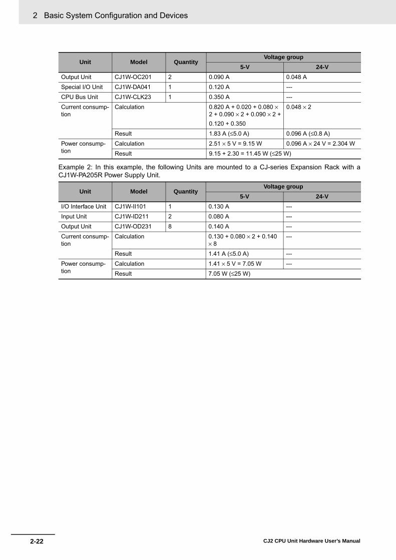
2 Basic System Configuration and Devices
2-22 CJ2 CPU Unit Hardware User’s Manual
Example 2: In this example, the following Units are mounted to a CJ-series Expansion Rack with aCJ1W-PA205R Power Supply Unit.
Output Unit CJ1W-OC201 2 0.090 A 0.048 A
Special I/O Unit CJ1W-DA041 1 0.120 A ---
CPU Bus Unit CJ1W-CLK23 1 0.350 A ---
Current consump-tion
Calculation 0.820 A + 0.020 + 0.080 ×2 + 0.090 × 2 + 0.090 × 2 +0.120 + 0.350
0.048 × 2
Result 1.83 A (≤5.0 A) 0.096 A (≤0.8 A)
Power consump-tion
Calculation 2.51 × 5 V = 9.15 W 0.096 A × 24 V = 2.304 W
Result 9.15 + 2.30 = 11.45 W (≤25 W)
Unit Model QuantityVoltage group
5-V 24-VI/O Interface Unit CJ1W-II101 1 0.130 A ---
Input Unit CJ1W-ID211 2 0.080 A ---
Output Unit CJ1W-OD231 8 0.140 A ---
Current consump-tion
Calculation 0.130 + 0.080 × 2 + 0.140 × 8
---
Result 1.41 A (≤5.0 A) ---
Power consump-tion
Calculation 1.41 × 5 V = 7.05 W ---
Result 7.05 W (≤25 W)
Unit Model QuantityVoltage group
5-V 24-V

2-23
2 Basic System Configuration and Devices
CJ2 CPU Unit Hardware User’s Manual
2-1 Basic System
Configuration
2
2-1-5 Calculating U
nit Current C
onsumption
Additional Information
Rack Current Consumption and Width Display
To display the current consumption and width of Units connected in the CPU Rack or ExpansionRack, select Current Consumption and Width from the Options Menu in the CJ2 CPU Unit I/OTable Window.
If the capacity of a Power Supply Unit is exceeded, it will be displayed in red.
Power SupplyUnit model
Currentconsumptionat 5 V
Currentconsumptionat 26/24 V
Total powerconsumption
Indicateslong-distanceexpansion
Width

2 Basic System Configuration and Devices
2-24 CJ2 CPU Unit Hardware User’s Manual
The ambient operating temperature at the control panel for mounting a CJ-series PLC must be nohigher than 55°C. This section describes how to calculate the power consumption of a CPU Rack foruse in the thermal design of the control panel.
Use the following equation to calculate the average power consumption (W) of a CJ-series CPU Rack.
� Basic PLC Power Consumption (W_PLC)The basic PLC power consumption is calculated based on the overall power consumption of thePLC and the power conversion rate of the Power Supply Unit.
W_PLC = W_unit ÷ η• W_unit:
Total power consumption of Units mounted to the CPU Rack. For details on the current consump-tion and voltage of individual Units, refer to 2-1-4 Configuration Units.
• η:Power Supply Unit power conversion rate.
The rate is 70% for the CJ Series, so use “0.7” in the calculation.
� Basic I/O Unit Power Consumption (W_IO_ONOFF)The Basic I/O Unit power consumption is the total consumption for the Input Units and the OutputUnits.• Input Units
Rated input voltage × Input current × Number of input points• Output Units
Residual voltage × Maximum load current × Number of output points
Note For the CJ Series, calculate the residual voltage at 0.1 V.
2-1-6 Calculating Power Consumption
Calculating Power Consumption
W = W_PLC + W_IO_ONOFFBasic I/O Unit power consumptionBasic PLC power consumption
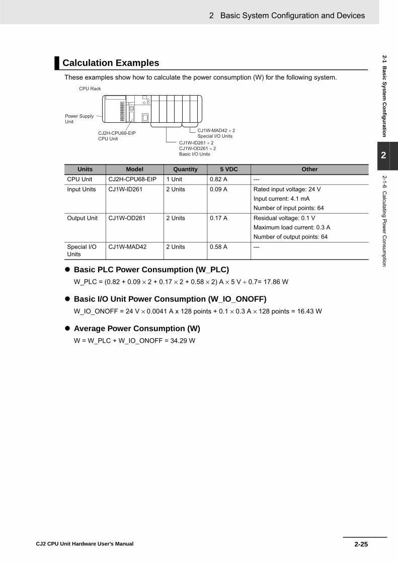
2-25
2 Basic System Configuration and Devices
CJ2 CPU Unit Hardware User’s Manual
2-1 Basic System
Configuration
2
2-1-6 Calculating Pow
er Consum
ption
These examples show how to calculate the power consumption (W) for the following system.
� Basic PLC Power Consumption (W_PLC)W_PLC = (0.82 + 0.09 × 2 + 0.17 × 2 + 0.58 × 2) A × 5 V ÷ 0.7= 17.86 W
� Basic I/O Unit Power Consumption (W_IO_ONOFF)W_IO_ONOFF = 24 V × 0.0041 A x 128 points + 0.1 × 0.3 A × 128 points = 16.43 W
� Average Power Consumption (W)W = W_PLC + W_IO_ONOFF = 34.29 W
Calculation Examples
Units Model Quantity 5 VDC OtherCPU Unit CJ2H-CPU68-EIP 1 Unit 0.82 A ---
Input Units CJ1W-ID261 2 Units 0.09 A Rated input voltage: 24 VInput current: 4.1 mANumber of input points: 64
Output Unit CJ1W-OD261 2 Units 0.17 A Residual voltage: 0.1 VMaximum load current: 0.3 ANumber of output points: 64
Special I/O Units
CJ1W-MAD42 2 Units 0.58 A ---
CPU Rack
Power Supply Unit
CJ2H-CPU68-EIPCPU Unit
CJ1W-MAD42 × 2Special I/O Units
CJ1W-ID261 × 2CJ1W-OD261 × 2Basic I/O Units

2 Basic System Configuration and Devices
2-26 CJ2 CPU Unit Hardware User’s Manual
2-2 Expanded System Configuration
This section describes the system configurations that can be connected by using the serial port that isbuilt into the CJ2 CPU Unit, along with Communications Units and other Configuration Units.
This expanded system can be connected via the CJ2 CPU Unit's built-in serial communications port ora Serial Communications Unit.
Various protocols, including Host Link and NT Link, can be used with the serial communications port. Aparticular protocol can be supported by switching the mode of the serial communications port.
For details on the serial communications modes that are supported, refer to 11-2 Serial Communica-tions in the CJ2 CPU Unit Software User’s Manual (Cat. No. W473).
Note Protocol macros are supported only for Serial Communications Units.
Precautions for Correct UsePrecautions for Correct Use
A Serial Option Board is required to use a serial communications for the CJ2M-CPU3@.
Refer to Serial Option Boards on page 2-7 for information on Serial Option Boards.
2-2-1 Serial Communications
PERIPHERAL
ERR/ ALMRUN
INH
COMMPRPHL
CONTROLLERPROGRAMMABLE
PORT
OPEN
BUSYMCPWR
BKUP
CPU64-EIPCJ2HSYSMAC
NSMS
COMM
10M100M
2
ON
4
TERM
RD2SD2RDY
NO.UNIT
ERH
OFF
WIRE
ERCRUNSCU41
RD1 TER1SD1
PORT1(RS422/485)
PORT2
2
ON
4
TERM
RD2SD2RDY
NO.UNIT
ERH
OFF
WIRE
ERCRUNSCU41
RD1 TER1SD1
PORT1(RS422/485)
PORT2
2
ON
4
TERM
RD2SD2RDY
NO.UNIT
ERH
OFF
WIRE
ERCRUNSCU41
RD1 TER1SD1
PORT1(RS422/485)
PORT2
15 Serial CommunicationsUnits max.
CPU Unit
Serial port (RS-232C)
Communications Port 1
Communications Port 2

2-27
2 Basic System Configuration and Devices
CJ2 CPU Unit Hardware User’s Manual
2-2 Expanded System C
onfiguration
2
2-2-1 Serial C
omm
unications
The host computer or a Programming Device, such as the CX-Programmer, is connected via the serialport on the CPU Unit or, with the CJ2M-CPU3@, on the Serial Option Board. In addition, up to 15 SerialCommunications Units can be connected to a single CPU Unit, making it possible to configure a flexibleserial communications system by connecting devices with RS-232C or RS-422/485 ports (such asPLCs from other manufacturers, temperature controllers, bar code readers, ID systems, personal com-puters, board computers, and components).
For details on the protocol modes that can be selected for each port, refer to 11-2-1 Overview of SerialCommunications in the CJ2 CPU Unit Software User’s Manual (Cat. No. W473).
Additional Information
Use the Peripheral Bus to connect the CJ2 CPU Unit to the CX-Programmer via serial communi-cations.
System Configuration Example
RS-232C
RS-232C
PT
CX-Programmeror host
computer
NT Link
CPU Unit
Peripheral Bus (Toolbus)
Host Link slave
SerialCommunications Units
Protocol macro
No protocol
Device supporting CompoWay/FDevice supporting Modbus
CPU UnitHost Link slave
General-purpose external device (e.g., such as a PLC from other manufacturer, temperature controller, or bar code reader)
: Protocol
*4
CJ2M, CJ1M, CP1H, CP1L, or CP1E CPU Unit
Serial PLC Link
CompoWay/F master
Modbus master
Host Link master
*4
*4
*1
*2
*3
*1 Serial port (RS-232C): A serial port is built into only the CJ2H CPU Units and the CJ2M-CPU1@ CPU Units.
*2 Serial Option Board: A Serial Option Board can be mounted only to a CJ2M-CPU3@ CPU Unit.
*3 Serial PLC Links are supported only by CJ2M CPU Units.
*4 This is connected using the Serial Gateway. The Serial Gateway is supported for Serial Communications Units with unit version 1.2 or later.
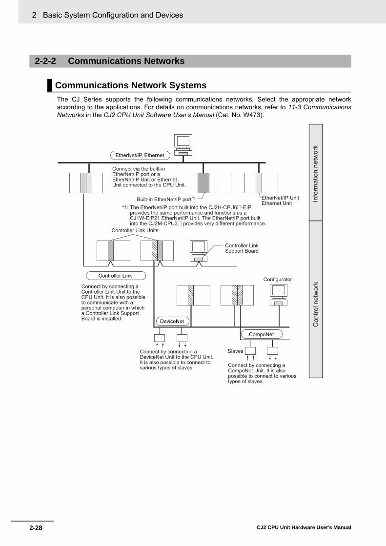
2 Basic System Configuration and Devices
2-28 CJ2 CPU Unit Hardware User’s Manual
‘
The CJ Series supports the following communications networks. Select the appropriate networkaccording to the applications. For details on communications networks, refer to 11-3 CommunicationsNetworks in the CJ2 CPU Unit Software User’s Manual (Cat. No. W473).
2-2-2 Communications Networks
Communications Network Systems
DeviceNet
CompoNet
EtherNet/IP, Ethernet
Controller Link
Info
rmat
ion
netw
ork
Con
trol n
etw
ork
EtherNet/IP UnitEthernet Unit
Connect via the built-in EtherNet/IP port or a EtherNet/IP Unit or Ethernet Unit connected to the CPU Unit.
Built-in EtherNet/IP port*1
*1: The EtherNet/IP port built into the CJ2H-CPU6@-EIPprovides the same performance and functions as a CJ1W-EIP21 EtherNet/IP Unit. The EtherNet/IP port built into the CJ2M-CPU3@ provides very different performance.
Controller Link Units
Controller Link Support Board
Connect by connecting a Controller Link Unit to the CPU Unit. It is also possible to communicate with a personal computer in which a Controller Link Support Board is installed.
Configurator
Connect by connecting a DeviceNet Unit to the CPU Unit. It is also possible to connect to various types of slaves.
Slaves
Connect by connecting a CompoNet Unit. It is also possible to connect to various types of slaves.

2-29
2 Basic System Configuration and Devices
CJ2 CPU Unit Hardware User’s Manual
2-2 Expanded System C
onfiguration
2
2-2-2 Com
munications N
etworks
Communications Network OverviewSystem Network Function Communications Communications Device
Information networks
EtherNet/IP Between Host computer and PLC.
FINS message communications Built-in EtherNet/IP port on CJ2H-CPU6@-EIP or Ether-Net/IP Unit Between PLCs.
Between Host computer and Memory Card installed in CPU Unit.
FTP server
Controller Link Between PLC and personal computer directly connected to the Network.
FINS message communications Controller Link Support Board or Controller Link UnitData link (offset, simple settings)
RS-232C → Controller Link Between Host Link computer and PLC on the Network.
Host Link commands and gate-way.
RS-232C cables and Con-troller Link Unit
Control networks
EtherNet/IP Between PLCs. Tag data links Built-in EtherNet/IP port on CJ2H-CPU6@-EIP, CJ2M-CPU3@ or EtherNet/IP Unit
Controller Link Between PLCs. FINS message communications Controller Link Unit
Data link (offset, simple settings)
DeviceNet FINS message communications in an open network.
DeviceNet Master Unit and Configurator
DeviceNet Between PLC and Network devices (Slaves).
Large-capacity remote I/O (fixed or free allocation) in an open net-work
DeviceNet Master Unit and Configurator
CompoNet High-speed, multi-point, multi-node remote I/O in an open net-work
CompoNet Master Unit

2 Basic System Configuration and Devices
2-30 CJ2 CPU Unit Hardware User’s Manual

3-1CJ2 CPU Unit Hardware User’s Manual
3This section gives the parts of a CJ2 PLC and describes the functions of the parts.
3-1 CPU Units . . . . . . . . . . . . . . . . . . . . . . . . . . . . . . . . . . . . . . . . . . . . . . . . . . . . 3-23-1-1 CPU Section . . . . . . . . . . . . . . . . . . . . . . . . . . . . . . . . . . . . . . . . . . . . . . . . . . 3-23-1-2 Built-in EtherNet/IP Section (CJ2H-CPU6@-EIP and CJ2M-CPU3@ Only) . . . 3-8
3-2 Memory Card . . . . . . . . . . . . . . . . . . . . . . . . . . . . . . . . . . . . . . . . . . . . . . . . 3-133-2-1 Models and Specifications . . . . . . . . . . . . . . . . . . . . . . . . . . . . . . . . . . . . . . . 3-133-2-2 Operating Procedures . . . . . . . . . . . . . . . . . . . . . . . . . . . . . . . . . . . . . . . . . . 3-133-2-3 Installing and Removing . . . . . . . . . . . . . . . . . . . . . . . . . . . . . . . . . . . . . . . . 3-14
3-3 Serial Option Boards (CJ2M-CPU3@ Only) . . . . . . . . . . . . . . . . . . . . . . . . 3-173-3-1 Overview . . . . . . . . . . . . . . . . . . . . . . . . . . . . . . . . . . . . . . . . . . . . . . . . . . . . 3-17
3-4 Power Supply Units . . . . . . . . . . . . . . . . . . . . . . . . . . . . . . . . . . . . . . . . . . . 3-183-4-1 Models and Specifications . . . . . . . . . . . . . . . . . . . . . . . . . . . . . . . . . . . . . . . 3-183-4-2 Components . . . . . . . . . . . . . . . . . . . . . . . . . . . . . . . . . . . . . . . . . . . . . . . . . 3-213-4-3 Selecting a Power Supply Unit . . . . . . . . . . . . . . . . . . . . . . . . . . . . . . . . . . . . 3-24
3-5 CJ-series Basic I/O Units . . . . . . . . . . . . . . . . . . . . . . . . . . . . . . . . . . . . . . . 3-253-5-1 Basic I/O Units with Terminal Blocks . . . . . . . . . . . . . . . . . . . . . . . . . . . . . . . 3-253-5-2 Thirty-two/Sixty-four-point Basic I/O Units with Connectors . . . . . . . . . . . . . 3-27
3-6 I/O Control Units and I/O Interface Units . . . . . . . . . . . . . . . . . . . . . . . . . . 3-293-6-1 Component Names . . . . . . . . . . . . . . . . . . . . . . . . . . . . . . . . . . . . . . . . . . . . 3-293-6-2 System Configuration . . . . . . . . . . . . . . . . . . . . . . . . . . . . . . . . . . . . . . . . . . 3-29
Nomenclature and Functions

3 Nomenclature and Functions
3-2 CJ2 CPU Unit Hardware User’s Manual
3-1 CPU Units
3-1-1 CPU Section
Components and Functions
CJ2H-CPU6@-EIP CJ2H-CPU6@
CJ2M-CPU3@ CJ2M-CPU1@
6
54
8
1
2
3 9
7Inside the battery compartment
11
PERIPHERAL
ERR/ALMRUN
INH
COMMBKUP
PRPHLNS
MS
COMM
10M100M
CONTROLLER
CPU64-EIPCJ2HSYSMAC
PROGRAMMABLE
PORT
OPEN
BUSYMCPWR
11
1010 6
5
4
3
2
81
7
12
PERIPHERAL
ERR/ALMRUN
INH
COMMBKUP
PRPHLCONTROLLER
CPU64-EIPCJ2HSYSMAC
PROGRAMMABLE
PORT
OPEN
BUSYMCPWR
Inside the battery compartment
6
5
4
81
2
39
7
1111
1013
6
5
4
3
2
81
7
12
CP1W-CIF01RS-232COption Board
CP1W-CIF11 or CP1W-CIF12RS-422A/485Option Board

3-3
3 Nomenclature and Functions
CJ2 CPU Unit Hardware User’s Manual
3-1 CPU
Units
3
3-1-1 CP
U S
ection
1. Memory Card Indicators (Refer to 3-2 Memory Card.)Indicates the Memory Card status (access and power supply).
2. Simple Backup/Memory Card Power Supply Switch (Refer to 3-2 Memory Card.)Used to back up Memory Card data or turn OFF the power when removing the Memory Card.
3. Peripheral (USB) PortConnected to Programming Devices, such as the CX-Programmer
4. Memory Card Connector (Refer to 3-2 Memory Card.)Connects the Memory Card to the CPU Unit.
5. Memory Card (Refer to 3-2 Memory Card.)All CPU Unit data can be copied to a Memory Card to back up the data. If a Memory Card Adapter is used, the Memory Card can be mounted in the PCMIA slot in a personal computer.
6. Memory Card Eject Button (Refer to 3-2 Memory Card.)Press the eject button to remove the Memory Card from the CPU Unit.
7. SliderSecures the CPU Unit to the next Unit.
8. LED Indicators (Refer to the next page.)These indicators show the status of the CPU Unit:
• Normal operation• Errors• Output OFF status• Communications status for the peripheral (USB) and RS-
232C ports• Backup status between RAM and built-in flash memory9. DIP Switch (Refer to a following page.)
Sets operations, such as user memory protection, auto-matic program transfer by Memory Card, serial port com-munications mode, and simple backup.
10. RS-232C Serial Port (Refer to A-4 Connecting to a Serial Port on the CPU Unit.)Connected to Programming Devices, Host Computers, general-purpose external devices, Programmable Termi-nals, and other devices.
11. ConnectorConnected to the next Unit.
12. Built-in EtherNet/IP Section (CJ2H-CPU6@-EIP only) Refer to 3-1-2 Built-in EtherNet/IP Section (CJ2H-CPU6@-EIP only) for information on the built-in Ether-Net/IP Section.
13. Serial Option Boards (CJ2M-CPU3@ Only)An Option Board can be connected to the slot.
• CP1W-CIF01 RS-232C Option Board• RS-422A/485 Option Board
(CP1W-CIF11 (Maximum transmission distance: 50 m) or CP1W-CIF12 (Maximum transmission distance: 500 m))

3 Nomenclature and Functions
3-4 CJ2 CPU Unit Hardware User’s Manual
The CJ2 CPU Unit status can be checked with the indicators at the top of the front panel of the Unit.The following table describes these indicators.
*1 The CJ2M-CPU3@ does not have this indicator. *2 Do not turn OFF the power supply to the PLC while this indicator is lit.
CPU Unit Status Indicators
Indicator Color Status MeaningRUN Green ON Lights when the PLC is operating normally in MONITOR or RUN
mode. The program is being executed.
Flashing System download mode error or DIP switch settings error.
OFF PLC has stopped operating while in PROGRAM mode, or has stopped operating due to a fatal error, or is downloading data from the system.
ERR/ALM Red ON A fatal error (including FALS(007) instruction execution) or a hard-ware error (watchdog timer error) was found in self-diagnosis. The CJ2 CPU Unit will stop operating, and the outputs from all Output Units will turn OFF.
Flashing A non-fatal error was found (including FAL(006) instruction execu-tion) in the self-diagnosis. The CJ2 CPU Unit will continue operating.
OFF The CJ2 CPU Unit is operating normally.
INH Yellow ON Output OFF Bit (A500.15) has been turned ON.The outputs from all Output Units will turn OFF.
OFF Output OFF Bit (A500.15) has been turned OFF.
PRPHL Yellow Flashing The CJ2 CPU Unit is communicating (sending or receiving) via the peripheral (USB) port.
OFF The CJ2 CPU Unit is not communicating via the peripheral (USB) port.
COMM*1 Yellow Flashing The CJ2 CPU Unit is communicating (sending or receiving) via the serial port (RS-232C).
OFF The CJ2 CPU Unit is not communicating via the serial port(RS-232C).
BKUP Yellow ON User program and parameter area data is being backed up to flash memory in the CPU Unit or being restored from flash mem-ory after the power supply to the PLC was turned ON. *2
OFF Data is not being written to flash memory.
Indicators on front of CPU Unit
7-segment display and indicators for EtherNet/IP port (Refer to 3-1-2Built-in EtherNet/IP Section.)(CJ2H-CPU6@-EIP and CJ2M-CPU3@ only.)

3-5
3 Nomenclature and Functions
CJ2 CPU Unit Hardware User’s Manual
3-1 CPU
Units
3
3-1-1 CP
U S
ection
The status of a Memory Card mounted in the CJ2 CPU Unit can be checked with the indicators in themiddle of the front panel of the Unit. The following table describes these indicators.
Memory Card Indicators
Indicator Color Status MeaningMCPWR Green Lit Power is being supplied to the Memory Card.
Flashing Flashes once: Simple backup read, write, or verify normalFlashes five times: Simple backup read malfunctionFlashes continuously: Simple backup write or verify malfunction
Not lit Power is not being supplied to the Memory Card.
BUSY Yellow Flashing Memory Card is being accessed.
Not lit Memory Card is not being accessed.
OPEN
PERIPHERAL
BUSY
MCPWR

3 Nomenclature and Functions
3-6 CJ2 CPU Unit Hardware User’s Manual
*1 The following data cannot be overwritten when pin 1 is ON:• All parts of the user program (programs in all tasks)• All data in the parameter area (such as the PLC Setup and I/O table)
When pin 1 is ON, the user program and parameter area will not be cleared when the memory clear opera-tion is performed from a Programming Device.
*2 I/O memory files (AUTOEXEC.IOM and ATEXEC@@@.IOM) are automatically transferred when power isturned ON if pin 2 is set to ON. Both the program (AUTOEXEC.OBJ) and parameter area (AUTOEXEC.STD)files must be stored on the Memory Card. It is not necessary for the I/O memory files (AUTOEXEC.IOM andATEXEC@@@.IOM) to be stored on the Memory Card.
*3 When pin 7 is ON, simple backup reading from the Memory Card is given priority, so even if pin 2 is ON, theuser program is not automatically transferred from the Memory Card when power is turned ON.
*4 Connecting to the PLC is not possible from the CX-One Support Software using SYSMAC WAY even if pin 5 onthe DIP switch is OFF and the PLC Setup is set to the Host Link protocol (i.e., the default setting).
*5 With the CJ2M-CPU3@, pin 5 can be set only when a Serial Option Board is mounted.
DIP Switch
Pin no. Usage Setting Function Default
SW1 Used to prevent programs from being accidentally overwritten from Program-ming Devices (including the CX-Program-mer).
ON Writing disabled for user program memory.*1 OFF
OFF Writing enabled for user program memory.
SW2 Set to ON to read the program (AUTOEXEC.OBJ file) and parameter area (AUTOEXEC.STD file) from the Memory Card to the CPU Unit when power is turned ON.*2
Used to store the programs in the Mem-ory Card to switch operations, or to auto-matically transfer programs at startup (Memory Card ROM operation).*3
ON The user program is automatically trans-ferred from the Memory Card when power is turned ON.
OFF
OFF The user program is not automatically trans-ferred from the Memory Card when power is turned ON.
SW3 Not used. --- --- OFF
SW4 Not used. --- --- OFF
SW5 Set to ON to automatically detect the baud rate of the CX-Programmer (periph-eral bus only) when using the serial port (RS-232C).*4, *5
ON Serial port (RS-232C) communications con-dition: Automatically detect CX-Programmer (peripheral bus only) baud rate.
OFF
OFF Serial port (RS-232C) communications con-dition: According to CX-Programmer commu-nications settings in PLC Setup. (Refer to Table 1.)
SW6 Set pin 6 to ON or OFF and use A395.12 in the program to create a user-defined condition without using an Input Unit.
ON User-defined pin. Turns ON the User DIP Switch Pin Flag (A395.12).
OFF
OFF User-defined pin. Turns OFF the User DIP Switch Pin Flag (A395.12).
SW7 Set the simple backup type. (Refer to Table 2 below.)
--- Specifies the simple backup type. OFF
SW8 --- Always OFF.
--- OFF
12
34
56
78
ON

3-7
3 Nomenclature and Functions
CJ2 CPU Unit Hardware User’s Manual
3-1 CPU
Units
3
3-1-2 Built-in E
therNet/IP
Section (C
J2H-C
PU
6@-E
IP only)
*1 Set using the CX-Programmer.*2 Connection is not possible from CX-One Support Software using the SYSMAC WAY protocol.
*1 This operation is given priority over automatic transfer at startup (pin 2 set to ON).
Note After reading data from the Memory Card to the CPU Unit using the simple backup operation, the CPU Unitwill remain in PROGRAM mode and no operations in any other mode will be possible. To switch to RUN orMONITOR mode, turn OFF the power, turn OFF pin 7, turn the power back ON, and use a ProgrammingDevice to change the operating mode.
Table 1
Setting Pin 5 of DIP switch on front panel PLC Setup (Serial port (RS-232C))*1
Connection1. Peripheral bus(automatic detection)
ON ---
2. Peripheral bus OFF (default) Peripheral bus
3. Host Link*2 OFF (default) Host Link (default)
4. NT Link OFF (default) NT Link
5. No-protocol OFF (default) No-protocol
6. Serial Gateway OFF (default) Serial Gateway
Table 2
Simple backup typeDIP Switch
Required operationSW7
Backing up all PLC data on the Memory Card: ON Press the Memory Card Power Supply Switch for 3 s.
Restoring all PLC data from the Memory Card: Turn ON the power to the PLC.*1
Comparing the Memory Card and the CPU Unit: OFF Press the Memory Card Power Supply Switch for 3 s.
All PLC dataMemory Card
Backup
All PLC data
Memory Card
Restore
All PLC data
Memory Card
Compare

3 Nomenclature and Functions
3-8 CJ2 CPU Unit Hardware User’s Manual
This section describes the components related to the EtherNet/IP port section that is built into theCJ2H-CPU6@-EIP and CJ2M-CPU3@.
Additional Information
The built-in EtherNet/IP port on the CJ2H-CPU6@-EIP provides the same performance andfunctions as a CJ1W-EIP21 EtherNet/IP Unit. (The performance of the built-in EtherNet/IP porton the CJ2M-CPU3@ is very different.) Set the unit number and node address with the rotaryswitches on the front panel of the CPU Unit, and set the communications parameters with theEdit Parameters menu command for the Special I/O Unit. For details on the Edit Parameters,refer to 8-2 Setting CPU Bus Units and Special I/O Units in the CJ2 CPU Unit Software User’sManual (Cat. No. W473). For details on specifications and settings for the built-in EtherNet/IPport, refer to the CS/CJ Series EtherNet/IP Units Operation Manual (Cat. No. W465).
With a CJ2 CPU Unit, Ethernet node status and Ethernet network status can be monitored by checkingthe display and indicators at the upper right of the front of the CPU Unit.
3-1-2 Built-in EtherNet/IP Section (CJ2H-CPU6@-EIP and CJ2M-CPU3@Only)
Nomenclature and Functions
CJ2H-CPU6@-EIP CJ2M-CPU3@
Display and Indicators for Built-in EtherNet/IP Port
AREHPIREP L
NS MS
COMM
10M100M CONTROLLER
CPU64-EIPCJ2HSYSMAC
PROGRAMMABLE
PORT
OPEN
BUSYMCPWR
Display and indicators for built-in EtherNet/IP port
Rotary switches
Built-in EtherNet/IP port (Refer to 5-3-6 Wiring with Ethernet Cable.)
Seven-segment display and indicatorsfor built-in EtherNet/IP port

3-9
3 Nomenclature and Functions
CJ2 CPU Unit Hardware User’s Manual
3-1 CPU
Units
3
3-1-2 Built-in E
therNet/IP
Section (C
J2H-C
PU
6@-E
IP only)
� Status Indicators: MS, NS, COMM, 100M, and 10M
The MS (Module Status) indicator indicates the status of the built-in EtherNet/IP port itself and theNS (Network Status) indicator indicates the status of the network.
The COMM, 100M, and 10M indicators indicate the status of Ethernet communications.
The MS and NS indicators can be green or red. The COMM, 100M, and 10M indicators are yellow.These indicators can be lit, flashing, or not lit. The following table shows the meaning of these indi-cator conditions.
Refer to SECTION 6 Troubleshooting for details on using these indicators for troubleshooting.
� Seven-segment Display
When the power supply to the PLC is turned ON or the CPU Unit is reset, all of the segments willflash twice, and then the IP address set for the built-in EtherNet/IP port will be displayed on the 7-segment display from right to left. After the entire IP address is displayed, the lower 8 bits of the IPaddress (node address) will be displayed in hexadecimal.
Indicator Name Color Status MeaningMS Module Status Red Lit Fatal error
Flashing Recoverable error
Green Lit Normal
--- Not lit Power supply OFF
NS Network Status Red Lit Fatal error
Flashing Recoverable error
Green Lit Tag data link and message connections established
Flashing Tag data link and message connections not established
--- Not lit Offline or power supply OFF
COMM Communication Yellow Lit Transferring data
Not lit Not transferring data
100M 100 Mbps Yellow Lit 100Base-TX link established
Not lit 100Base-TX link not established
10M 10 Mbps Yellow Lit 10Base-TX link established
Not lit 10Base-TX link not established

3 Nomenclature and Functions
3-10 CJ2 CPU Unit Hardware User’s Manual
For example, the display will change as follows if the IP address is 192.168.250.10:
If an error occurs, the error code will be displayed alternately with the rightmost byte of the affecteddevice’s IP address. For details on error codes, refer to 6-2-2 Checking Error Status at the Ether-Net/IP Port Seven-segment Display.
The following examples show the displays for errors. • A d6 error (failure to connect) has occurred in communications with IP address 192.168.250.8.• A d6 error (failure to connect) has occurred in communications with IP address 192.168.250.9.• A d5 error (verification error; target missing) has occurred in communications with IP address
192.168.250.40.• A C6 error (multiple switches ON) and an EA error (EtherNet/IP expansion setting error) have
occurred at the built-in EtherNet/IP port (192.168.250.10).
: 0A
The IP address is displayed in decimal, flowing from right to left.
If the Unit is operating normally, the rightmost digitsof the Unit's IP address is displayed in hexadecimal.Flashing: The tag data links are stopped.Lit: The tag data links are operating.
( “0A” is the hexadecimal displayfor the final row, 10, in the IPaddress of the local Unit.)
: 10
: 250.
: 168.
: 192.
Example:
Example:
: Er d6 IP 08
: IP d6 IP 09
: Er d5 IP 40
: Er c6
: Er EA
: IP 0A
Information on errors that occur in communications with the target node, along with the last digits of the Unit’ s IP address, are displayed in hexadecimal.
Displays errors that occurred within the Unit.
The last digits of the Unit’ s IP address is displayed in hexadecimal.

3-11
3 Nomenclature and Functions
CJ2 CPU Unit Hardware User’s Manual
3-1 CPU
Units
3
3-1-2 Built-in E
therNet/IP
Section (C
J2H-C
PU
6@-E
IP only)
• There is no priority to the order in which the errors are displayed. All of the errors are displayedrepeatedly in sequence.
Left/Right Dot LEDs
If an error occurs at multiple devices for which the rightmost 8 bits in the IP addresses are the same,this is indicated by the dots on the right side in display on the target devices.
The following examples show the displays for multiple errors.• d6 errors (failure to connect) have occurred in communications with IP address 10.0.1.8.• d6 errors (failure to connect) have occurred in communications with IP address 10.0.2.8.
The unit number and node address for the CJ2 CPU Unit built-in EtherNet/IP port are set using therotary switches. The unit number and node address are allocated in the same way as for a CPU BusUnit. According to the unit number that is set, words are automatically allocated in the CIO Area andDM Area. For details, refer to the CJ2 CPU Unit Software User’s Manual (Cat. No. W473).
� Setting the Unit NumberSet a unique unit number for the CJ2 CPU Unit built-in EtherNet/IP port. The same unit number can-not be used by any other CPU Bus Unit connected to the CJ2 CPU Unit.
Use a small screwdriver to make the setting, and be sure not to damage the rotary switch. The unitnumber is factory-set to 0.
Precautions for Correct UsePrecautions for Correct Use
• Always turn OFF the PLC’s power supply before setting the unit number.• When setting the unit number for the first time or when changing the setting, create the PLC’s
I/O tables.
Rotary Switches
Setting range0 to F

3 Nomenclature and Functions
3-12 CJ2 CPU Unit Hardware User’s Manual
� Node Address Setting SwitchesSet a FINS address for the built-in EtherNet/IP port. With the FINS communications service, multipleEtherNet/IP Units (including the CJ2 Unit built-in EtherNet/IP port) connected by Ethernet are identi-fied by their node addresses. Using the node address switches, set a unique node address in hexa-decimal. The same node address cannot be used by any other EtherNet/IP Unit or Ethernet Unitconnected on the same Ethernet network.
As long as it does not duplicate any other address, the node address can be set from 01 to FE (1 to254 in decimal).
Note The node address is factory-set to 01. With the default setting, the values set on these switches become thelast two digits of the built-in EtherNet/IP port’s IP address.
The default IP address is 192.168.250.node_address. With the factory-set node address of 01, thedefault IP address is 192.168.250.1.
The node address can be set to any number in the setting range (01 to FE), as long as the sameaddress is not set on another node in the network.
Precautions for Correct UsePrecautions for Correct Use
• Always turn OFF the PLC’s power supply before setting the unit number.• When setting the unit number for the first time or when changing the setting, create the PLC’s
I/O tables.
Additional Information
• If the node address setting is changed during operation, the MS Indicator will flash red.
� Relationship with IP AddressWhen using the automatic generation method (dynamic/static) for IP address conversion, the right-most byte of the IP address that is set for the built-in EtherNet/IP port must be set to the same valueas the node address. If it cannot be set to the same value as the node address, then the addressconversion method must be set to the IP address table method or the IP address + automatic gener-ation method. For details, refer to the CS/CJ Series EtherNet/IP Units Operation Manual (Cat. No.W465).
Setting range01 to FE hex (1 to 254 decimal)

3-13
3 Nomenclature and Functions
CJ2 CPU Unit Hardware User’s Manual
3-2 Mem
ory Card
3
3-2-1 Models and S
pecifications
3-2 Memory Card
Use the following OMRON-specified Memory Card. Operation may not be correct if memory cards fromother companies are used.
Additional Information
Simple BackupThe simple backup function copies all CPU Unit data (user program, parameters, and I/O mem-ory) to a Memory Card, without having to use a Programming Device.
For details, refer to 8-3 Simple Backup.
3-2-1 Models and Specifications
Model number HMC-EF583 HMC-EF283 HMC-EF183
Memory Card capacity 512 Mbytes 256 Mbytes 128 Mbytes
Common specifi-cations
Dimensions 42.8 × 36.4 × 3.3 mm (W × H × T)
Weight 15 g max.
Current consumption Approx. 30 mA (when used with PLC)
Environmental specifications Same as general specifications of PLC
No. of writes 100,000 (guaranteed value)
Factory specifi-cations
No. of files writable to root directory
511
File system FAT16
3-2-2 Operating Procedures
Memory Card Eject Button
Memory Card IndicatorsMCPWR (green): Lit when power is being provided to the Memory Card.BUSY (orange): Flashes while the Memory Card is being accessed.
Simple Backup/Memory Card Power Supply SwitchThis switch has the following two functions.
• Simple BackupTo back up all CPU Unit data to the Memory Card, press this switch for 3 s when DIP switch pin 7 is set to ON.
• Turning OFF Power to the Memory CardPress this switch to turn OFF the power before removing the Memory Card.
LAREHPIREP

3 Nomenclature and Functions
3-14 CJ2 CPU Unit Hardware User’s Manual
• Observe the following precautions while the Memory Card is being accessed. The Memory Card maybecome unusable if these precautions are not followed.• Never turn OFF the PLC while the CPU is accessing the Memory Card.• Never remove the Memory Card while the CPU is accessing the Memory Card. Press the Memory
Card power supply switch and wait for the BUSY indicator to go OFF before removing the MemoryCard.
• Never insert the Memory Card facing the wrong way. If the Memory Card is inserted forcibly, it maybecome unusable.
• To delete all the data on the Memory Card by formatting the Memory Card, insert the Memory Card inthe CPU Unit and perform the operation from the CX-Programmer.
1 Pull the top end of the Memory Card cover forward and remove from the Unit.
2 Insert the Memory Card with the label facing to the left. (Insert with the Δ on the Memory Cardlabel and the Δ on the CPU Unit facing each other.)
3 Push the Memory Card securely into the compartment.
If the Memory Card is inserted correctly, the Memory Card eject button will be pushed out.
3-2-3 Installing and Removing
Before Using a Memory Card
Installing the Memory Card
Product label

3-15
3 Nomenclature and Functions
CJ2 CPU Unit Hardware User’s Manual
3-2 Mem
ory Card
3
3-2-3 Installing and Rem
oving
1 Press the Memory Card power supply switch.
2 Press the Memory Card eject button after the BUSY indicator is no longer lit.
The Memory Card will be ejected from the compartment.
3 Pull out the Memory Card.
4 Install the Memory Card cover when a Memory Card is not being used.
Removing the Memory Card
Memory Card power supply switch
Memory Card eject button
BUSY indicator

3 Nomenclature and Functions
3-16 CJ2 CPU Unit Hardware User’s Manual
Installing the Memory Card into a Personal ComputerHMC-AP001Memory Card Adapter
Memory Card
Personal computer PC card slot
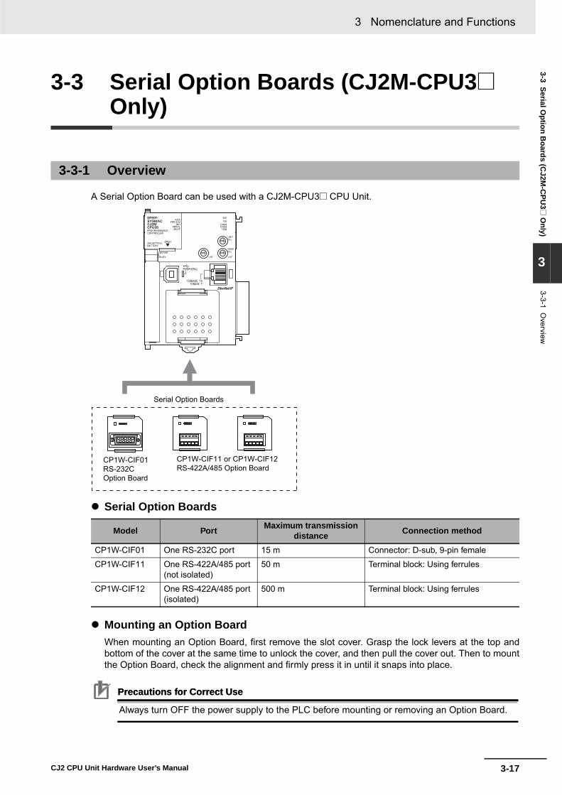
3-17
3 Nomenclature and Functions
CJ2 CPU Unit Hardware User’s Manual
3-3 Serial Option B
oards (CJ2M
-CPU
3@ O
nly)
3
3-3-1 Overview
3-3 Serial Option Boards (CJ2M-CPU3@Only)
A Serial Option Board can be used with a CJ2M-CPU3@ CPU Unit.
� Serial Option Boards
� Mounting an Option BoardWhen mounting an Option Board, first remove the slot cover. Grasp the lock levers at the top andbottom of the cover at the same time to unlock the cover, and then pull the cover out. Then to mountthe Option Board, check the alignment and firmly press it in until it snaps into place.
Precautions for Correct UsePrecautions for Correct Use
Always turn OFF the power supply to the PLC before mounting or removing an Option Board.
3-3-1 Overview
Model Port Maximum transmission distance Connection method
CP1W-CIF01 One RS-232C port 15 m Connector: D-sub, 9-pin female
CP1W-CIF11 One RS-422A/485 port (not isolated)
50 m Terminal block: Using ferrules
CP1W-CIF12 One RS-422A/485 port (isolated)
500 m Terminal block: Using ferrules
CP1W-CIF01RS-232COption Board
CP1W-CIF11 or CP1W-CIF12 RS-422A/485 Option Board
Serial Option Boards
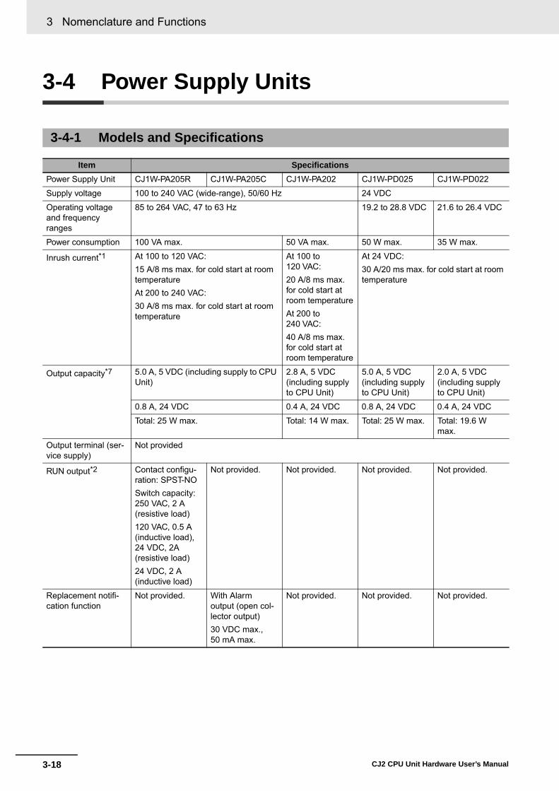
3 Nomenclature and Functions
3-18 CJ2 CPU Unit Hardware User’s Manual
3-4 Power Supply Units
3-4-1 Models and Specifications
Item SpecificationsPower Supply Unit CJ1W-PA205R CJ1W-PA205C CJ1W-PA202 CJ1W-PD025 CJ1W-PD022
Supply voltage 100 to 240 VAC (wide-range), 50/60 Hz 24 VDC
Operating voltage and frequency ranges
85 to 264 VAC, 47 to 63 Hz 19.2 to 28.8 VDC 21.6 to 26.4 VDC
Power consumption 100 VA max. 50 VA max. 50 W max. 35 W max.
Inrush current*1 At 100 to 120 VAC:15 A/8 ms max. for cold start at room temperatureAt 200 to 240 VAC:30 A/8 ms max. for cold start at room temperature
At 100 to 120 VAC:20 A/8 ms max. for cold start at room temperatureAt 200 to 240 VAC:40 A/8 ms max. for cold start at room temperature
At 24 VDC:30 A/20 ms max. for cold start at room temperature
Output capacity*7 5.0 A, 5 VDC (including supply to CPU Unit)
2.8 A, 5 VDC (including supply to CPU Unit)
5.0 A, 5 VDC (including supply to CPU Unit)
2.0 A, 5 VDC (including supply to CPU Unit)
0.8 A, 24 VDC 0.4 A, 24 VDC 0.8 A, 24 VDC 0.4 A, 24 VDC
Total: 25 W max. Total: 14 W max. Total: 25 W max. Total: 19.6 W max.
Output terminal (ser-vice supply)
Not provided
RUN output*2 Contact configu-ration: SPST-NOSwitch capacity: 250 VAC, 2 A (resistive load)120 VAC, 0.5 A (inductive load), 24 VDC, 2A (resistive load)24 VDC, 2 A (inductive load)
Not provided. Not provided. Not provided. Not provided.
Replacement notifi-cation function
Not provided. With Alarm output (open col-lector output)30 VDC max., 50 mA max.
Not provided. Not provided. Not provided.

3-19
3 Nomenclature and Functions
CJ2 CPU Unit Hardware User’s Manual
3-4 Power Supply U
nits
3
3-4-1 Models and S
pecifications
Insulation resistance 20 MΩ min. (at 500 VDC) between AC external and GR terminals*3
• 20 MΩ min. (at 500 VDC) between all external termi-nals and GR terminal, and between all alarm output terminals.
• 20 MΩ min. (at 250 VDC) between all alarm output terminals and GR terminal.
20 MΩ min. (at 500 VDC) between AC external and GR terminals*3
20 MΩ min. (at 500 VDC) between DC external and GR terminals*3
---*6
Dielectric strength*4 2,300 VAC 50/60 Hz for 1 min between AC external and GR terminals*3
Leakage current: 10 mA max.
• 2,300 VAC, 50/60 Hz for 1 min between all external ter-minals and GR terminal and between all alarm output terminals with a leakage current of 10 mA max.
• 1,000 VAC, 50/60 Hz for 1 min between all alarm output terminals and GR terminal with a leakage current of 10 mA max.
2,300 VAC 50/60 Hz for 1 min between AC external and GR terminals*3
Leakage current: 10 mA max.
1,000 VAC 50/60 Hz for 1 min between DC external and GR terminals*3
Leakage current: 10 mA max.
---*6
1,000 VAC 50/60 Hz for 1 min between DC external and GR terminals*3
Leakage current: 10 mA max.
Noise immunity 2 kV on power supply line (Conforms to IEC61000-4-4.)
Vibration resistance 5 to 8.4 Hz, 3.5-mm amplitude, 8.4 to 150 Hz, acceleration: 9.8 m/s2 in X, Y, and Z directions for 100 minutes (Time coefficient: 10 minutes × coefficient factor 10 = total time 100 min.) (according to JIS C60068-2-6)
Shock resistance 147 m/s2 3 times each in X, Y, and Z directions (Relay Output Unit: 100 m/s2) (according to JIS C60068-2-27)
Ambient operating temperature
0 to 55°C
Ambient operating humidity
10% to 90% (with no condensation)
10% to 90% (with no condensa-tion)*5
10% to 90% (with no condensation)
Atmosphere Must be free from corrosive gases.
Ambient storage tem-perature
−20 to 75°C(excluding bat-tery)
−20 to 75°C*5 −20 to 75°C (excluding battery)
Item Specifications

3 Nomenclature and Functions
3-20 CJ2 CPU Unit Hardware User’s Manual
*1 The AC and DC values above are given for a cold start, and the AC values are at room temperature. The AC inrush con-trol circuit uses a thermistor element with a low-temperature current control characteristic. If the ambient temperature ishigh or the PLC is hot-started, the thermistor will not be sufficiently cool, and the inrush current given in the table may beexceeded by up to twice the given value. When selecting fuses or breakers for external circuits, allow sufficient margin inshut-off performance. The DC inrush control circuit uses a capacitor-charging delay circuit. If the power is OFF for only ashort time for a hot-start, the capacitor will not sufficiently charge and the inrush current given in the table may beexceeded by up to twice the given value.
*2 Supported only when mounted to CPU Rack.*3 Disconnect the Power Supply Unit’s LG terminal from the GR terminal when testing insulation and dielectric strength.
Testing the insulation and dielectric strength with the LG terminal and the GR terminals connected will damage internalcircuits in the CPU Unit.
*4 Change the applied voltage gradually using the adjuster on the Tester. If the full dielectric strength voltage is applied orturned OFF using the switch on the Tester, the generated impulse voltage may damage the Power Supply Unit.
*5 Maintain an ambient storage temperature of −25 to 30°C and relative humidity of 25% to 70% when storing the Unit forlonger than 3 months to keep the replacement notification function in optimum working condition.
*6 CJ1W-PD022 is not insulated between the primary DC power and secondary DC power.*7 Internal components in the Power Supply Unit will deteriorate or be damaged if the Power Supply Unit is used for an
extended period of time exceeding the power supply output capacity or if the outputs are shorted.

3-21
3 Nomenclature and Functions
CJ2 CPU Unit Hardware User’s Manual
3-4 Power Supply U
nits
3
3-4-2 Com
ponents
� Example: CJ1W-PA205R
� Example: CJ1W-PA205C
� Example: CJ1W-PA202
3-4-2 Components
POWER
PA205R
DC24VAC240V
OUTPUTRUN
INPUTAC100-240V
L2/N
L1
POWER IndicatorLit when 5 V are being output from the Power Supply Unit.
External connection terminals
RUN output
AC input
LG
GR
POWER
Years
CJ1W-PA205C
TEST
NC
NC
AC100-240VINPUT
L2/N
L1
L+
ALARMOUTPUTDC30V,50mA
NORMAL:ONALARM :OFF
POWER IndicatorLit when 5 V are being output from the Power Supply Unit.
External connectionterminals
AC input
LG
GR
Alarm output(replacement notification output)
TEST switchThe TEST switch can be used totemporarily turn OFF the alarm outputthat notifies when replacement isneeded.
Replacement notification display
POWER
PA202
INPUT
NC
NC
AC100-240V
L2/N
L1
POWER IndicatorLit when 5 V are being output from the Power Supply Unit.
External connectionterminals
AC input
LG
GR
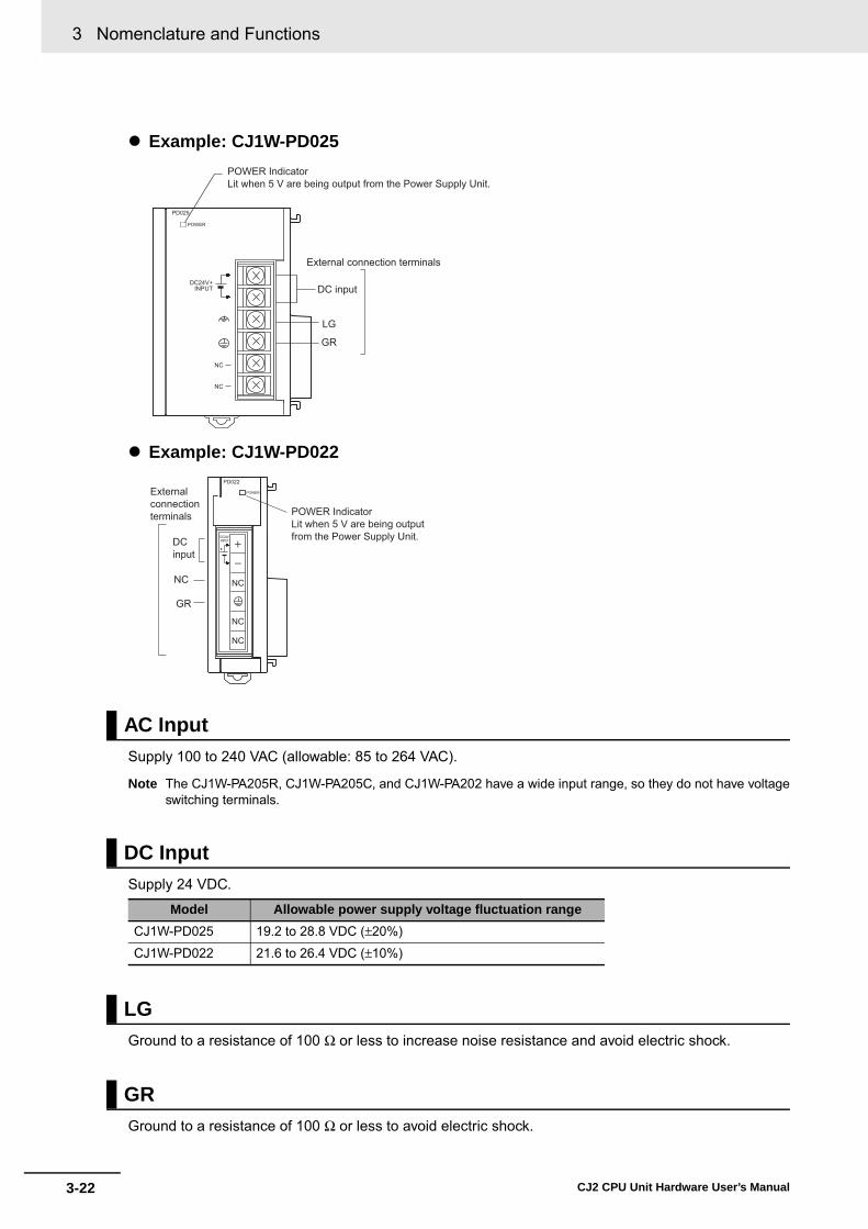
3 Nomenclature and Functions
3-22 CJ2 CPU Unit Hardware User’s Manual
� Example: CJ1W-PD025
� Example: CJ1W-PD022
Supply 100 to 240 VAC (allowable: 85 to 264 VAC).
Note The CJ1W-PA205R, CJ1W-PA205C, and CJ1W-PA202 have a wide input range, so they do not have voltageswitching terminals.
Supply 24 VDC.
Ground to a resistance of 100 Ω or less to increase noise resistance and avoid electric shock.
Ground to a resistance of 100 Ω or less to avoid electric shock.
AC Input
DC Input
Model Allowable power supply voltage fluctuation rangeCJ1W-PD025 19.2 to 28.8 VDC (±20%)
CJ1W-PD022 21.6 to 26.4 VDC (±10%)
LG
GR
POWER
PD025
DC24V+INPUT
NC
NC
POWER IndicatorLit when 5 V are being output from the Power Supply Unit.
External connection terminals
DC input
LG
GR
POWER
PD022
NC
NC
NC
DC24VINPUT
+
POWER IndicatorLit when 5 V are being output from the Power Supply Unit.
Externalconnectionterminals
DCinput
NC
GR

3-23
3 Nomenclature and Functions
CJ2 CPU Unit Hardware User’s Manual
3-4 Power Supply U
nits
3
3-4-2 Com
ponents
The internal contact turns ON when the CJ2 CPU Unit is operating (RUN or MONITOR mode). ThePower Supply Unit must be in the CPU Rack to use this output.
The alarm output is used to notify when Power Supply Unit replacement is required. The output is nor-mally ON. The output turns OFF when the time until replacement is 6 months or less.
RUN Output (CJ1W-PA205R Only)
Alarm Output (CJ1W-PA205C Only)

3 Nomenclature and Functions
3-24 CJ2 CPU Unit Hardware User’s Manual
After determining what power supply voltage is required, whether power output terminals and a RUNoutput are required, and whether replacement notification is required, calculate the current and powerrequirements for each Rack.
There are two voltage groups for internal power consumption: 5 VDC and 24 VDC.
For details on the current consumption of individual Units, refer to 2-1-4 Configuration Units.
� Current Consumption at 5 VDCThe following table shows the current that can be supplied to Units (including the CJ2 CPU Unit) thatuse 5-VDC power.
� Current Consumption at 24 VDCThe following table shows the current that can be supplied to Units that use 24-VDC power supply.
The following table shows the maximum total power that can be supplied at 5 VDC and 24 VDC.
For details on the current consumption of individual Units, refer to 2-1-2 CPU Rack, 2-1-3 ExpansionRacks, and 2-1-4 Configuration Units. Refer to 2-1-5 Calculating Unit Current Consumption for anexample of calculating the current consumption.
3-4-3 Selecting a Power Supply Unit
Condition 1: Current Requirements
Model Maximum current at 5 VDCCJ1W-PA205R/205C 5.0 A
CJ1W-PA202 2.8 A
CJ1W-PD025 5.0 A
CJ1W-PD022 2.0 A
Model Maximum current at 24 VDCCJ1W-PA205R/205C 0.8 A
CJ1W-PA202 0.4 A
CJ1W-PD025 0.8 A
CJ1W-PD022 0.4 A
Condition 2: Power Requirements
Model Maximum total power outputCJ1W-PA205R/205C 25 W
CJ1W-PA202 14 W
CJ1W-PD025 25 W
CJ1W-PD022 19.6 W

3-25
3 Nomenclature and Functions
CJ2 CPU Unit Hardware User’s Manual
3-5 CJ-series B
asic I/O U
nits
3
3-5-1 Basic I/O
Units w
ith Terminal B
locks
3-5 CJ-series Basic I/O Units
� Eight/sixteen-point Units (18-point Terminal Blocks)
Note The CJ1W-OD202, CJ1W-OD204, and CJ1W-OD212 also have an ERR indicator for the load short-circuitalarm.
� FunctionsInterrupt Input Units are used to execute interrupt programs on the rising or falling edge of an inputsignal. When the specified interrupt input turns ON (or OFF), execution of the cyclic program in theCPU Unit is interrupted and an I/O interrupt task (task number 100 to 131) is executed. When execu-tion of the I/O interrupt task has been completed, the cyclic program is again executed starting fromthe instruction after which it was interrupted.
3-5-1 Basic I/O Units with Terminal Blocks
Part Names and Functions
Interrupt Input Units
ERR0 1 2 3 4 5 6 7
8 9 10 11 12 13 14 15
ConnectorConnect to the connector on the next Unit.
I/O indicators
Model number label
Terminal block for I/O wiring, 18P × 1
Interrupt Input Unit CPU Unit
Input(rising orfallingedge)
Immediateinterrupt
1 cyclic task
I/O interrupt task
I/O interrupt task isexecuted when the inputturns ON (or OFF).
MSKS

3 Nomenclature and Functions
3-26 CJ2 CPU Unit Hardware User’s Manual
� Application Precautions• Interrupt Input Units must be mounted in the locations described below.
When using a CJ2H-CPU6@-EIP CPU Unit, all Interrupt Input Units must be connected in any of thefour positions immediately to the right of the CPU Unit, i.e., slots 0 to 3 on the CPU Rack. Whenusing a CJ2H-CPU6@ CPU Unit or CJ2M-CPU@@ Unit, all Interrupt Input Units must be connectedin any of the five positions immediately to the right of the CPU Unit, i.e., slots 0 to 4 on the CPURack. If an Interrupt Input Unit is connected in any other position on the CPU Rack or anywhere onan Expansion Rack, and I/O setting error (fatal) will occur.
Example: CJ2H-CPU6@-EIP
• The Interrupt Input Units must be connected in the slot ranges specified above even when the I/Otables are edited using the CX-Programmer. If the Interrupt Input Units are not connected in the cor-rect positions, an error will occur when the I/O tables are generated from the CX-Programmer.A401.10 will turn ON to indicate an I/O setting error and A405.08 will turn ON to indicate that an Inter-rupt Input Unit is in the wrong position.
Note Even if a Unit is physically in one of the correct positions, a Dummy Unit can be registered in the I/O tables,causing a Unit to be defined in a position different from its physical position.
• There are limits to the number of Interrupt Input Units that can be mounted. If these limits areexceeded, a too many I/O points error (fatal error) will occur.
• The input response time cannot be changed for the CJ1W-INT01, and the related portions of theBasic I/O Unit input time constants in the PLC Setup, and the setting status in A200 to A259 will notbe valid.
� Input Signal WidthInput signals must meet the following conditions.
Unit ON time OFF timeCJ1W-INT01 0.05 ms min. 0.5 ms min.
0 1 2 3 4 5 6 7 8 9
PowerSupplyUnit
CPUUnit
Connect here. Cannot be used.
ON OFF

3-27
3 Nomenclature and Functions
CJ2 CPU Unit Hardware User’s Manual
3-5 CJ-series B
asic I/O U
nits
3
3-5-2 Thirty-two/S
ixty-four-point Basic I/O
Units w
ith Connectors
Units are available with either Fujitsu-compatible connectors (CJ1W-@D@@1) or MIL connectors(CJ1W-@D@@2/3/4).
� Thirty-two-point Units (Models with 40-point Fujitsu Connector or MIL Connector)
� Thirty-two-point Units with 2 × 24-pin Fujitsu-compatible Connectors or 2 × 20-pin MIL Connectors
3-5-2 Thirty-two/Sixty-four-point Basic I/O Units with Connectors
Part Names
ID 2 3 1 ID 2 3 2
Model number
I/O indicators
Unit with MIL ConnectorUnit with Fujitsu-compatibleConnector
ConnectorConnected to the connector on the next Unit.
Indicator Switch1 2
Changes the 16 I/O displayed on the I/O indicators.
Wd m (Row A on connector)Fujitsu connector MIL connector
Bottom of connectorTop of connectorWd m+1 (Row B on connector)
Setting 1Setting 2
Word morm+1
I/O wiringconnector(40-pin × 1)
0 1 2 34 5 6 78 912 13 14 15
10 11
ERR
Note: Only the CJ1W-OD232 has an ERR indicator for the load short-circuit alarm.
Model number
Unit with MIL Connector
ConnectorConnected to the connector on the next Unit.
Unit with Fujitsu-compatible Connector
I/O wiring connector(24-pin x 2)
I/O indicators
Word m
Word m+1
MD231
0 1 2 3 4 5 6 78 9 12 13 14 1510 110 1 2 3 4 5 6 78 9 12 13 14 1510 11
MD232

3 Nomenclature and Functions
3-28 CJ2 CPU Unit Hardware User’s Manual
� Sixty-four-point Units (Models with Two 40-point Fujitsu Connectors or MIL Connector)
ID 2 6 1
0 1 2 3 4 5 6 78 9 1 21 31 41 51 01 10 1 2 3 4 5 6 78 9 1 21 31 41 51 01 1
I
II
ID 2 6 1
Model number
I/O indicators
Unit with MIL ConnectorUnit with Fujitsu-compatibleConnector
ConnectorConnected to the connector on the next Unit.
Indicator Switch
1 2
Changes the 32 I/O displayed on the I/O indicators.
Setting 1Setting 2
I/O wiringconnector(40-pin × 2)
Wd m and m+1: CN1Wd m+2 and m+3: CN2
Word m orm+2Word m+1or m+3

3-29
3 Nomenclature and Functions
CJ2 CPU Unit Hardware User’s Manual
3-6 I/O C
ontrol Units and I/O
Interface Units
3
3-6-1 Com
ponent Nam
es
3-6 I/O Control Units and I/O Interface Units
An I/O Control Unit and I/O Interface Units are used to connect Expansion Racks to expand the system.
Precautions for Correct UsePrecautions for Correct Use
Attached the enclosed cover to the I/O Connecting Cable connector on the I/O Interface Unitwhen it is not being used to protect it from dust.
3-6-1 Component Names
3-6-2 System Configuration
The I/O Control Unit is connected directly to the CJ2 CPU Unit. If it is not immediately to the right of the CPU Unit, correct operation may not be possible.The I/O Interface Unit is connected directly to the Power Supply Unit. If it is not immediately to the right of the Power Supply Unit, correct oper-ation may not be possible.
TUO101CI
TUO INII101
CJ1W-II101I/O Interface Unit
CJ1W-IC101I/O Control Unit
Output connector forI/O Connecting Cable
Output connector forI/O Connecting Cable
Input connector forI/O Connecting Cable
PowerSupply Unit
PowerSupply Unit
PowerSupply Unit
CPU Unit
CPU Rack
Expansion Rack
CJ1W-IC101I/O Control Unit
CJ1W-II101I/O Interface Unit
I/O Connecting Cable
I/O Connecting Cable
CJ1W-II101I/O Interface Unit

3 Nomenclature and Functions
3-30 CJ2 CPU Unit Hardware User’s Manual

4-1CJ2 CPU Unit Hardware User’s Manual
4This section describes the software that is used to program and debug a CJ2 PLC. Italso describes how to connect the Programming Device and the PLC.
4-1 Support Software . . . . . . . . . . . . . . . . . . . . . . . . . . . . . . . . . . . . . . . . . . . . . . 4-24-1-1 CX-One FA Integrated Tool Package . . . . . . . . . . . . . . . . . . . . . . . . . . . . . . . . 4-2
4-2 Connection Methods . . . . . . . . . . . . . . . . . . . . . . . . . . . . . . . . . . . . . . . . . . . 4-54-2-1 Connecting by USB . . . . . . . . . . . . . . . . . . . . . . . . . . . . . . . . . . . . . . . . . . . . . 4-54-2-2 Connecting by RS-232C . . . . . . . . . . . . . . . . . . . . . . . . . . . . . . . . . . . . . . . . . 4-74-2-3 Connecting to Ethernet (CJ2H-CPU6@-EIP and CJ2M-CPU3@ Only) . . . . . 4-9
Support Software

4 Support Software
4-2 CJ2 CPU Unit Hardware User’s Manual
4-1 Support Software
“Support Software” refers to software applications for programming and debugging OMRON Program-mable Controllers.
The CX-One provides an integrated package of Support Software for OMRON PLCs and components.It consists of software applications for PLC programming, network settings, touch-panel screen cre-ation, servo control, inverters, temperature control, and other functions.
4-1-1 CX-One FA Integrated Tool Package
CX-One Integrated Tool Package Contents
PT
SSR
NV-Designer
CX-Thermo CX-Drive
CX-Integrator
CX-Motion-NCF
CX-Motion
CX-Protocol
CX-One
CX-Position
CX-Simulator
CX-Programmer
CX-Motion-MCH
CX-Process
SwitchBox Utility
Face PlateAuto-Builder for NSNetwork
Configurator
CX-Designer
● Touch-panel screen creation
● Motion control● Programming/simulation
● Network settings
● Servo/Inverter settings
● Protocol macro creation
● Temperature control settings
● PLC-based process control
Networks between PLCs
Loop Controller
Devices by othermanufacturers
SerialFieldnetwork
Temperature control
Servo Inverter
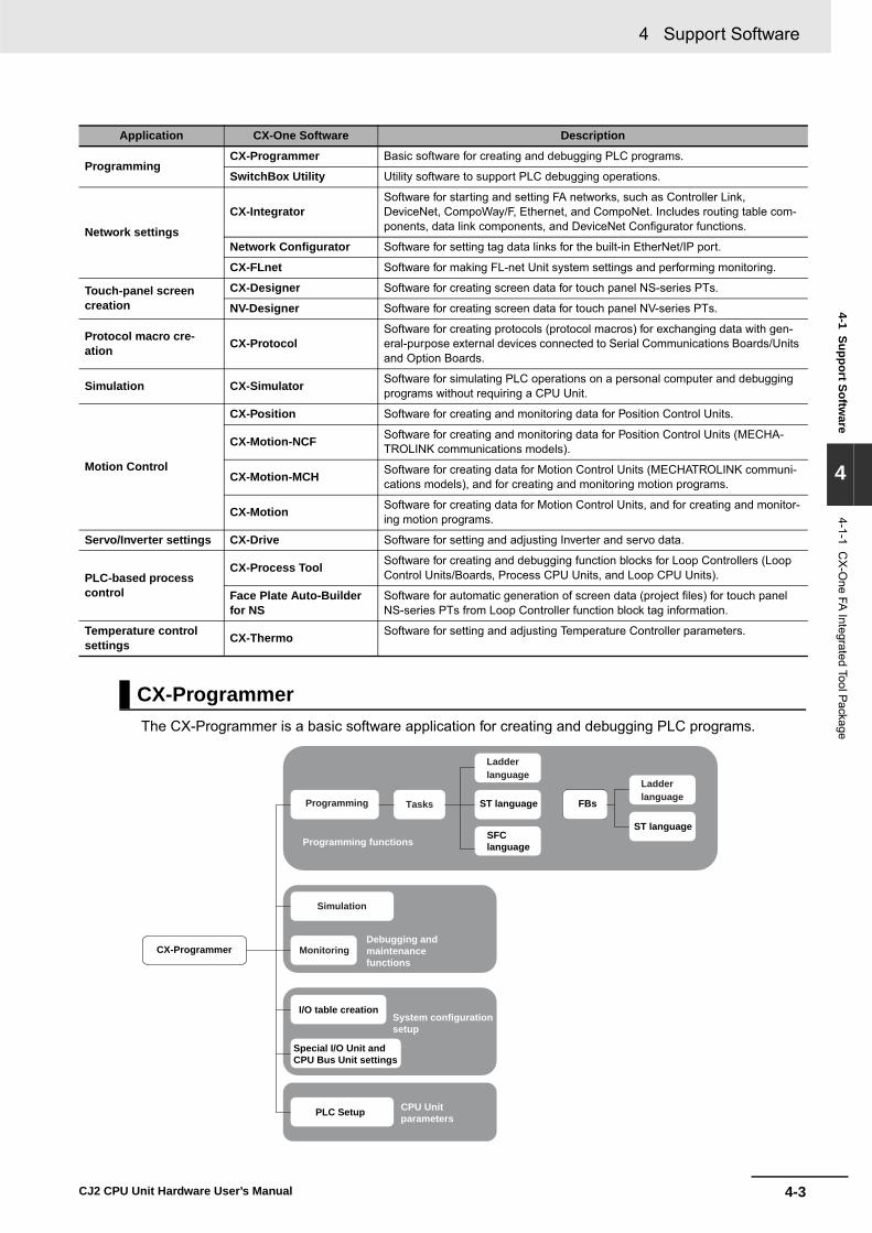
4-3
4 Support Software
CJ2 CPU Unit Hardware User’s Manual
4-1 Support Software
4
4-1-1 CX-O
ne FA Integrated Tool PackageThe CX-Programmer is a basic software application for creating and debugging PLC programs.
Application CX-One Software Description
ProgrammingCX-Programmer Basic software for creating and debugging PLC programs.
SwitchBox Utility Utility software to support PLC debugging operations.
Network settings
CX-IntegratorSoftware for starting and setting FA networks, such as Controller Link, DeviceNet, CompoWay/F, Ethernet, and CompoNet. Includes routing table com-ponents, data link components, and DeviceNet Configurator functions.
Network Configurator Software for setting tag data links for the built-in EtherNet/IP port.
CX-FLnet Software for making FL-net Unit system settings and performing monitoring.
Touch-panel screen creation
CX-Designer Software for creating screen data for touch panel NS-series PTs.
NV-Designer Software for creating screen data for touch panel NV-series PTs.
Protocol macro cre-ation CX-Protocol
Software for creating protocols (protocol macros) for exchanging data with gen-eral-purpose external devices connected to Serial Communications Boards/Units and Option Boards.
Simulation CX-Simulator Software for simulating PLC operations on a personal computer and debugging programs without requiring a CPU Unit.
Motion Control
CX-Position Software for creating and monitoring data for Position Control Units.
CX-Motion-NCF Software for creating and monitoring data for Position Control Units (MECHA-TROLINK communications models).
CX-Motion-MCH Software for creating data for Motion Control Units (MECHATROLINK communi-cations models), and for creating and monitoring motion programs.
CX-Motion Software for creating data for Motion Control Units, and for creating and monitor-ing motion programs.
Servo/Inverter settings CX-Drive Software for setting and adjusting Inverter and servo data.
PLC-based process control
CX-Process Tool Software for creating and debugging function blocks for Loop Controllers (Loop Control Units/Boards, Process CPU Units, and Loop CPU Units).
Face Plate Auto-Builder for NS
Software for automatic generation of screen data (project files) for touch panel NS-series PTs from Loop Controller function block tag information.
Temperature control settings CX-Thermo Software for setting and adjusting Temperature Controller parameters.
CX-Programmer
Programming functions
CX-Programmer
I/O table creation
FBsST language
ST languageSFClanguage
PLC Setup
Debugging and maintenancefunctions
System configuration setup
CPU Unit parameters
Special I/O Unit and CPU Bus Unit settings
Programming
Simulation
Monitoring
Tasks
Ladderlanguage
Ladderlanguage
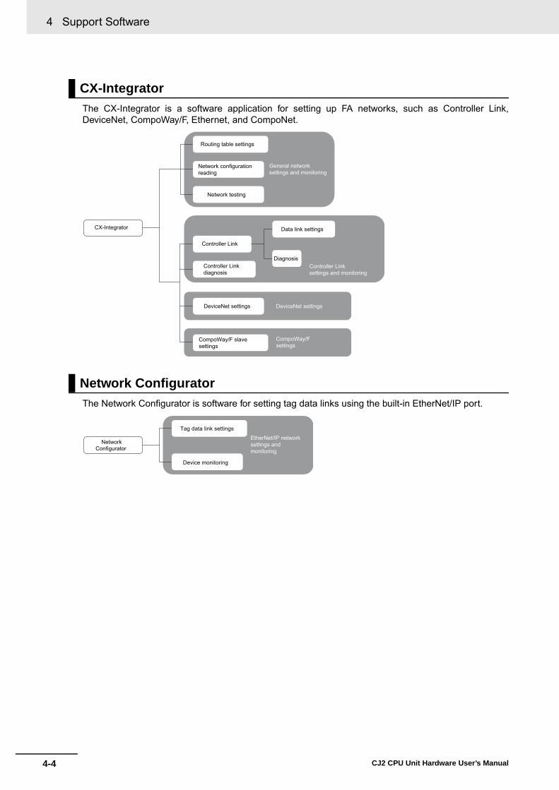
4 Support Software
4-4 CJ2 CPU Unit Hardware User’s Manual
The CX-Integrator is a software application for setting up FA networks, such as Controller Link,DeviceNet, CompoWay/F, Ethernet, and CompoNet.
The Network Configurator is software for setting tag data links using the built-in EtherNet/IP port.
CX-Integrator
Network Configurator
General network settings and monitoring
CX-Integrator
DeviceNet settings
Controller Linkdiagnosis
CompoWay/F slave settings
Controller Link
Data link settings
Diagnosis
Routing table settings
Network configurationreading
Network testing
Controller Linksettings and monitoring
DeviceNet settings
CompoWay/Fsettings
Network Configurator
Tag data link settings
Device monitoring
EtherNet/IP network settings and monitoring

4-5
4 Support Software
CJ2 CPU Unit Hardware User’s Manual
4-2 Connection M
ethods
4
4-2-1 Connecting by U
SB
4-2 Connection Methods
A CJ2 CPU Unit can be directly connected to a personal computer running the CX-One Support Soft-ware (e.g., CX-Programmer) by using a USB cable or RS-232C cable. (The CP1W-CIF01 is required touse a RS-232C cable with the CJ2M-CPU3@.) Also, an Ethernet twisted-pair cable can be used for theCJ2H-CPU6@-EIP or CJ2M-CPU3@.
Using commercially available USB cable, connect CX-One Support Software via a standard peripheral(USB) port at the personal computer.
*1 Commercially available USB cable: 5 m max., for USB 1.1 or 2.0.
Use the following cable to connect the CJ2 CPU Unit to the computer running the Support Software.
In order to connect the PLC to a personal computer by USB, a USB driver must be installed in the per-sonal computer. The USB driver for USB connections is automatically stored in the following directory inthe personal computer when CX-One is installed:
C:\Program Files\OMRON\CX-Server\USB\Win2000_XP\inf
When the personal computer is connected to the PLC by USB cable, the personal computer automati-cally recognizes the device and the USB driver installation is started. For details on how to install theUSB driver, refer to A-5 Installing the USB Driver.
4-2-1 Connecting by USB
Connection Method
Connecting Cable
Port at Unit Port at computer
Network type (communications
mode)Model Length Remarks
Peripheral (USB) port (Conforms to USB 2.0, B connector)
USB port 12 Mbps, USB 2.0 Commercially available USB cable (A connector - B connector)
5 m max. ---
Before Connecting
CX-One (e.g., CX-Programmer)
Commercially availableUSB cable*1
Peripheral (USB) port (conforming to USB 2.0, B connector)
A connector USB port
B connectorCJ2 CPU Unit

4 Support Software
4-6 CJ2 CPU Unit Hardware User’s Manual
The method for connecting the PLC to the personal computer is set using the CX-Programmer. Fordetails on using the CX-Programmer to set the connection method, refer to the CJ2 CPU Unit SoftwareUser’s Manual (Cat. No. W473).
Based on USB specifications, the following restrictions apply when connecting a personal computerand components.• Only one CJ2 CPU Unit can be connected by USB to a single personal computer. It is not possible to
connect multiple CJ2 CPU Units simultaneously.• Do not remove the USB cable while connected online. The application must be offline before the
cable is removed. If the cable is removed while connected online, one of the following situations willoccur depending on the operating system.• Windows 2000/XP
The Support Software online status will not be restored by simply re-inserting the USB cable.Once the Support Software has gone offline, the cable must be re-inserted and the Support Soft-ware online connection operation must be repeated.
• Windows 98/MeIf the USB cable is removed while connected online, a blue error screen may be displayed. If thatoccurs, the personal computer must be restarted.
Additional Information
The USB port on a computer can be connected to the PLC serial port (RS-232C) by usingCJ1W-CIF31 USB-Serial Conversion Cable. (The USB driver for the CJ1W-CIF31 must beinstalled.)
Refer to A-5 Installing the USB Driver for the installation procedure for the USB driver.
CX-Programmer Settings
Restrictions on Connecting by USB
RS-232C port, D-sub connector (9-pin, female)
D-sub connector(9-pin, female)
Recommended cable: XW2Z-200S-CV/500S-CV or XW2Z-200S-V/500S-V*1
D-sub connector (9-pin, male) D-sub connector
(9-pin, male)
CJ2 CPU UnitCS1W-CIF31
USB A plug connector, male
*1 Only a Host Link connection is possible.

4-7
4 Support Software
CJ2 CPU Unit Hardware User’s Manual
4-2 Connection M
ethods
4
4-2-2 Connecting by R
S-232C
Using commercially available RS-232C cable, directly connect the CX-One Support Software (e.g., CX-Programmer) via a standard serial port at the personal computer.
The network type must be set to the Toolbus. A Host Link connection cannot be used.
Additional Information
Connecting to the PLC by EtherNet/IP via USB or RS-232CThe Support Software can be directly connected by USB or RS-232C to one CJ2 CPU Unit and access other CPU Units on the EtherNet/IP network via the built-in EtherNet/IP ports on the CJ2 CPU Units. For details, refer to the CJ2 CPU Unit Software User’s Manual (Cat. No. W473).
4-2-2 Connecting by RS-232C
Connection Method
D-sub connector (9-pin female)
CX-One (e.g., CX-Programmer)
CJ2 CPU Unit
D-sub connector (9-pin male)
Recommended cable: XW2Z-200S-CV/500S-CV
D-sub connector (9-pin male)
COMM
Serial port (RS-232C) (9-pin female D-sub connector) or Serial Option Board (for CJ2M-CPU3@)
USB
USB
Personal computer
Built-in EtherNet/IP port
EtherNet/IP
CJ2
Access is possible.
CJ2

4 Support Software
4-8 CJ2 CPU Unit Hardware User’s Manual
Use the following cable to connect the CJ2 CPU Unit to the computer running the Support Software.
*1 Connection is not possible from CX-One Support Software using the SYSMAC WAY (Host Link) protocol.
Precautions for Safe Use
• When the above cable connector is connected to the PLC serial port (RS-232C), be sure todischarge static electricity by touching grounded metal before touching the cable connector.The XW2Z-@@@S-CV Cable is particularly resistant to static electricity because it uses astatic-resistant connector hood (XM2S-0911-E). Even when this Cable is used, however, besure to discharge static electricity before touching the connector.
• Use the specialized cable described above for connecting cable. Using ordinary commerciallyavailable RS-232C cable for personal computers may result in damage to external devices andthe CPU Unit.
Additional Information
It is possible to create RS-232C cable for connecting to the serial port (RS-232C). The connec-tors shown in the following table are included with the CJ2 CPU Unit as standard equipment forcreating cables. For details on creating cables, refer to A-4 Connecting to a Serial Port on theCPU Unit.
Select the protocol for communications between the PLC and the CX-Programmer. For a SYSMACWAY (Host Link) connection, turn OFF pin 5 of the DIP switch on the front panel. For a peripheral busconnection (faster than SYSMAC WAY), turn ON pin 5.
The method for connecting the PLC to the personal computer is set using the CX-Programmer. Fordetails on using the CX-Programmer to set the connection method, refer to the CJ2 CPU Unit SoftwareUser’s Manual (Cat. No. W473).
Connecting Cable
Port at Unit Port at computer
Network type (communications
mode)Model Length Remarks
Serial port (RS-232C)(D-sub, 9-pin, female)
D-sub, 9-pin, male
Serial communications (Toolbus only*1)
XW2Z-200S-CV 2 m Use a static-resis-tant connector.XW2Z-500S-CV 5 m
Name Model SpecificationsPlug XM2A-0901 9-pin, male Use in combination. (One of
each is provided as standard equipment with the CPU Unit.)
Hood XM2S-0911-E 9-pin static-resistant connector with millimeter screws
Setting the Communications Protocol
CX-Programmer Settings

4-9
4 Support Software
CJ2 CPU Unit Hardware User’s Manual
4-2 Connection M
ethods
4
4-2-3 Connecting to E
thernet (CJ2H
-CP
U6@
-E
IP and C
J2M-C
PU
3@ O
nly)
With the CJ2H-CPU6@-EIP or CJ2M-CPU3@, use a commercially available Ethernet 100Base-TX STPtwisted-pair cable (straight) to connect the CX-One Support Software (e.g., CX-Programmer) to thebuilt-in EtherNet/IP port through the switching hub. With the CJ2H-CPU6@-EIP, Ethernet twisted-paircable can also be used to connect to a personal computer. The same type of connection can be madewith the CJ2H-CPU6@ or CJ2M-CPU1@ through an EtherNet/IP Unit.
Use the following cable to connect the CJ2 CPU Unit to the computer running the Support Software.
*1 Use 100Base-TX when using tag data links.*2 The following table shows the devices recommended for use with the built-in EtherNet/IP port.
*3 Always use a switching hub when using tag data links in the network. If a repeater hub is used for EtherNet/IPtag data links (cyclic communications), the network's communications load will increase, data collisions willoccur frequently, and stable communications will be impossible.
4-2-3 Connecting to Ethernet (CJ2H-CPU6@-EIP and CJ2M-CPU3@Only)
Connection Method
Connecting Cable
Port at Unit Port at computer
Network type (commu-nications mode) Model Length Remarks
Built-in Ether-Net/IP port
Ethernet port
100Base-TX or 10Base-T*1
Commercially available twisted-pair cable*2
100 m (Recommended between hub and nodes.)
---
Commercially available switching hub*2, *3
---
Part Manufacturer Model number Inquires
Switching Hub
Cisco Systems, Inc. Consult the manufacturer. Cisco Systems, Inc. Main Corporate HQ
Contec USA, Inc. Consult the manufacturer. CONTEC USA Inc.
Phoenix Contact Consult the manufacturer. Phoenix Contact USA Customer Service
Twisted-pair cable
100Base-TX
Fujikura F-LINK-E 0.5mm × 4P Fujikura America, Inc.
EtherNet/IP compliant cable ---
Connectors(Modular plug)
STP Plug
Panduit Corporation MPS588 Panduit Corporation US Headquarters
Boots Tsuko Company MK boot (IV) LV Tsuko Company Japan Headquarters
100Base-TXtwisted-pair cable (straight)
100Base-TXtwisted-pair cable (straight)
Switching hub
Built-in EtherNet/IP port
CJ2 CPU Unit
CX-One (e.g., CX-Programmer)
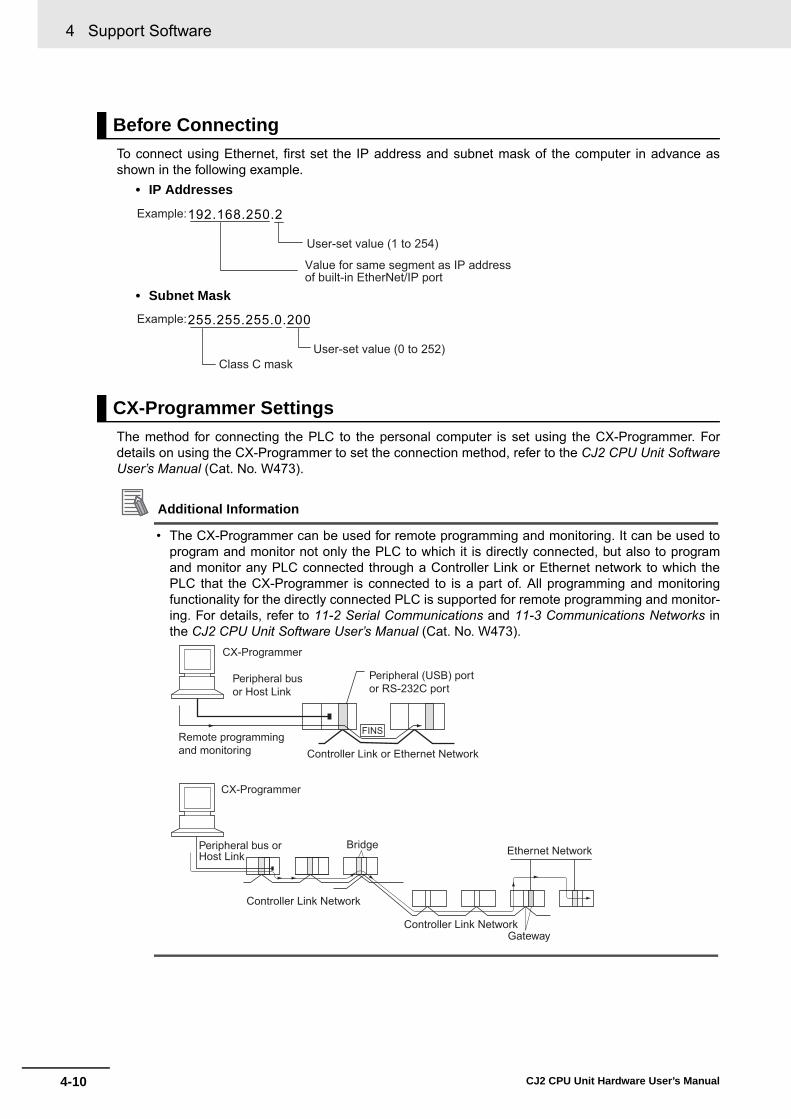
4 Support Software
4-10 CJ2 CPU Unit Hardware User’s Manual
To connect using Ethernet, first set the IP address and subnet mask of the computer in advance asshown in the following example.
• IP Addresses
• Subnet Mask
The method for connecting the PLC to the personal computer is set using the CX-Programmer. Fordetails on using the CX-Programmer to set the connection method, refer to the CJ2 CPU Unit SoftwareUser’s Manual (Cat. No. W473).
Additional Information
• The CX-Programmer can be used for remote programming and monitoring. It can be used toprogram and monitor not only the PLC to which it is directly connected, but also to programand monitor any PLC connected through a Controller Link or Ethernet network to which thePLC that the CX-Programmer is connected to is a part of. All programming and monitoringfunctionality for the directly connected PLC is supported for remote programming and monitor-ing. For details, refer to 11-2 Serial Communications and 11-3 Communications Networks inthe CJ2 CPU Unit Software User’s Manual (Cat. No. W473).
Before Connecting
CX-Programmer Settings
192.168.250.2 Example:
User-set value (1 to 254)
Value for same segment as IP address of built-in EtherNet/IP port
255.255.255.0.200Example:
User-set value (0 to 252)Class C mask
FINS
CX-Programmer
Peripheral bus or Host Link
Peripheral (USB) port or RS-232C port
Controller Link or Ethernet NetworkRemote programming and monitoring
CX-Programmer
Peripheral bus or Host Link
Bridge Ethernet Network
Controller Link NetworkGateway
Controller Link Network

4-11
4 Support Software
CJ2 CPU Unit Hardware User’s Manual
4-2 Connection M
ethods
4
4-2-3 Connecting to E
thernet (CJ2H
-CP
U6@
-E
IP and C
J2M-C
PU
3@ O
nly)
Precautions for Correct UsePrecautions for Correct Use
Connecting to a Programming Device through the built-in EtherNet/IP port will not be possible ifthe following errors occur:• I/O bus error• Too many I/O points error• Unit number duplication error• Rack number duplication error• I/O setting error
If any of the above errors occurs and connecting to the Programming Device through the built-inEtherNet/IP port is not possible, connect through the USB port.

4 Support Software
4-12 CJ2 CPU Unit Hardware User’s Manual

5-1CJ2 CPU Unit Hardware User’s Manual
5
This section describes how to install and wire a CJ2 PLC.
5-1 Fail-safe Circuits . . . . . . . . . . . . . . . . . . . . . . . . . . . . . . . . . . . . . . . . . . . . . . 5-2
5-2 Installation . . . . . . . . . . . . . . . . . . . . . . . . . . . . . . . . . . . . . . . . . . . . . . . . . . . 5-45-2-1 Installation and Wiring Precautions . . . . . . . . . . . . . . . . . . . . . . . . . . . . . . . . . 5-45-2-2 Installation in a Control Panel . . . . . . . . . . . . . . . . . . . . . . . . . . . . . . . . . . . . . 5-65-2-3 Assembled Appearance and Dimensions . . . . . . . . . . . . . . . . . . . . . . . . . . . . 5-85-2-4 Connecting PLC Components . . . . . . . . . . . . . . . . . . . . . . . . . . . . . . . . . . . . 5-135-2-5 DIN Track Installation . . . . . . . . . . . . . . . . . . . . . . . . . . . . . . . . . . . . . . . . . . . 5-155-2-6 Connecting CJ-series Expansion Racks . . . . . . . . . . . . . . . . . . . . . . . . . . . . 5-17
5-3 Wiring . . . . . . . . . . . . . . . . . . . . . . . . . . . . . . . . . . . . . . . . . . . . . . . . . . . . . . 5-205-3-1 Power Supply Wiring . . . . . . . . . . . . . . . . . . . . . . . . . . . . . . . . . . . . . . . . . . . 5-205-3-2 Wiring CJ-series Basic I/O Units with Terminal Blocks . . . . . . . . . . . . . . . . . 5-275-3-3 Wiring Basic I/O Units with Connectors . . . . . . . . . . . . . . . . . . . . . . . . . . . . . 5-295-3-4 Connecting to Connector-Terminal Block Conversion Units or
I/O Relay Terminals . . . . . . . . . . . . . . . . . . . . . . . . . . . . . . . . . . . . . . . . . . . . 5-335-3-5 Connecting I/O Devices . . . . . . . . . . . . . . . . . . . . . . . . . . . . . . . . . . . . . . . . . 5-345-3-6 Connecting through an Ethernet Cable
(CJ2H-CPU6@-EIP and CJ2M-CPU3@ Only) . . . . . . . . . . . . . . . . . . . . . . . . 5-38
5-4 Control Panel Installation . . . . . . . . . . . . . . . . . . . . . . . . . . . . . . . . . . . . . . 5-415-4-1 Temperature . . . . . . . . . . . . . . . . . . . . . . . . . . . . . . . . . . . . . . . . . . . . . . . . . . 5-415-4-2 Humidity . . . . . . . . . . . . . . . . . . . . . . . . . . . . . . . . . . . . . . . . . . . . . . . . . . . . . 5-435-4-3 Vibration and Shock . . . . . . . . . . . . . . . . . . . . . . . . . . . . . . . . . . . . . . . . . . . . 5-435-4-4 Atmosphere . . . . . . . . . . . . . . . . . . . . . . . . . . . . . . . . . . . . . . . . . . . . . . . . . . 5-435-4-5 Electrical Environment . . . . . . . . . . . . . . . . . . . . . . . . . . . . . . . . . . . . . . . . . . 5-445-4-6 Grounding . . . . . . . . . . . . . . . . . . . . . . . . . . . . . . . . . . . . . . . . . . . . . . . . . . . 5-49
Installation

5 Installation
5-2 CJ2 CPU Unit Hardware User’s Manual
5-1 Fail-safe Circuits
Be sure to set up safety circuits outside of the PLC to prevent dangerous conditions in the event oferrors in the PLC or external power supply.
Outputs from Units such as DC Output Units may malfunction momentarily when the power to the PLCis turned ON. This may cause problems in the system if the PLC's power supply is turned ON after thecontrolled system's power supply. To prevent possible malfunctions, add an external circuit that pre-vents the power supply to the controlled system from going ON before the power supply to the PLCitself.
When any of the following errors occurs, PLC operation will stop and all outputs from Output Units willbe turned OFF.• Operation of the Power Supply Unit's overcurrent protection circuit• A CPU error (watchdog timer error) or CPU on standby• A fatal error (memory error, Memory Card transfer error, I/O bus error, Unit/Rack number duplication
error, too many I/O points error, I/O setting error, program error, cycle time exceeded error, orFALS(007) error)*1
Be sure to add any circuits necessary outside of the PLC to ensure the safety of the system in the eventof an error that stops PLC operation.*1 When a fatal error occurs, all outputs from Output Units will be turned OFF even if the IOM Hold Bit has been
turned ON to protect the contents of I/O memory. (When the IOM Hold Bit is ON, the outputs will retain theirprevious status after the PLC has been switched from RUN/MONITOR mode to PROGRAM mode.)
It is possible for an output to remain ON due to a malfunction in the internal circuitry of the Output Unit,such as a relay or transistor malfunction. Be sure to add any circuits necessary outside of the PLC toensure the safety of the system in the event that an output fails to go OFF.
Order of Powering Up the CPU Unit and Controlled System
Managing CPU Unit Errors
Managing Output Malfunctions
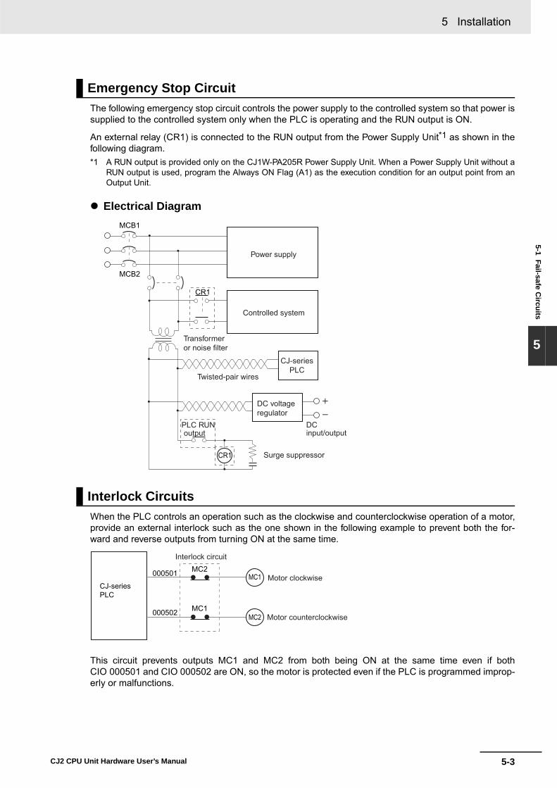
5-3
5 Installation
CJ2 CPU Unit Hardware User’s Manual
5-1 Fail-safe Circuits
5
The following emergency stop circuit controls the power supply to the controlled system so that power issupplied to the controlled system only when the PLC is operating and the RUN output is ON.
An external relay (CR1) is connected to the RUN output from the Power Supply Unit*1 as shown in thefollowing diagram.*1 A RUN output is provided only on the CJ1W-PA205R Power Supply Unit. When a Power Supply Unit without a
RUN output is used, program the Always ON Flag (A1) as the execution condition for an output point from anOutput Unit.
� Electrical Diagram
When the PLC controls an operation such as the clockwise and counterclockwise operation of a motor,provide an external interlock such as the one shown in the following example to prevent both the for-ward and reverse outputs from turning ON at the same time.
This circuit prevents outputs MC1 and MC2 from both being ON at the same time even if bothCIO 000501 and CIO 000502 are ON, so the motor is protected even if the PLC is programmed improp-erly or malfunctions.
Emergency Stop Circuit
Interlock Circuits
MCB1
MCB2
CR1
CR1
DCPLC RUN output input/output
Power supply
Controlled system
DC voltage regulator
Surge suppressor
Twisted-pair wires
Transformer or noise filter
CJ-series PLC
CJ-seriesPLC
MC2000501
MC1000502
MC1
MC2
Interlock circuit
Motor clockwise
Motor counterclockwise

5 Installation
5-4 CJ2 CPU Unit Hardware User’s Manual
5-2 Installation
When the PLC is being installed in a cabinet or control panel, be sure to provide proper ambient condi-tions as well as access for operation and maintenance.
� Temperature ControlThe ambient temperature within the enclosure must be within the operating range of 0 to 55°C.When necessary, take the following steps to maintain the proper temperature.• Provide enough space for good air flow.• Do not install the PLC above equipment that generates a large amount of heat such as heaters,
transformers, or high-capacity resistors.• If the ambient temperature exceeds 55°C, install a cooling fan or air conditioner.
� Accessibility for Operation and Maintenance• To ensure safe access for operation and maintenance, separate the PLC as much as possible
from high-voltage equipment and power machinery.• The PLC will be easiest to install and operate if it is mounted at a height of 1.0 to 1.6 m above the
floor.
� Improving Noise Resistance• Do not mount the PLC in a control panel containing high-voltage equipment.• Install the PLC at least 200 mm (6.5 feet) from power lines.
• Ground the mounting plate between the PLC and the mounting surface.• When I/O Connecting Cables are 10 m or longer, connect the control panels in which Racks are
mounted with heavier power wires (3 wires at least 2 mm2 in cross-sectional area).
5-2-1 Installation and Wiring Precautions
Installation in Cabinets or Control Panels
CJ-seriesPLC
Controlpanel
Fan
Louver
CJ-seriesPLC
Power lines
200 mm min.
200 mm min.

5-5
5 Installation
CJ2 CPU Unit Hardware User’s Manual
5-2 Installation
5
5-2-1 Installation and Wiring P
recautions
� PLC Orientation• Each Rack must be mounted in an upright position to provide proper cooling.
• Do not install a Rack in any of the following positions.
Precautions for Safe Use
Always use the standard installation method. A nonstandard installation will decrease heat dissi-pation, and may delay the replacement notification signal (in particular for Power Supply Unitswith Replacement Notification (CJ1W-PA205C)), or degrade or damage the internal elements.

5 Installation
5-6 CJ2 CPU Unit Hardware User’s Manual
A CJ-series PLC must be mounted inside a control panel on DIN Track. Normally the CPU Rack isinstalled on top and the Expansion Racks under it.
• Consider the width of wiring ducts, wiring, ventilation, and Unit replacement when determining thespace between Racks.
Additional Information
A CJ-series PLC must be mounted on DIN Track. It cannot be mounted with screws.
• Whenever possible, route I/O wiring through wiring ducts or raceways. Install the duct so that it iseasy to fish wire from the I/O Units through the duct. It is handy to have the duct at the sameheight as the Racks.
5-2-2 Installation in a Control Panel
Control Panel Installation Dimensions
DIN Track
Duct
Duct
Unit
20 mm min.
20 mm min.
DIN Track

5-7
5 Installation
CJ2 CPU Unit Hardware User’s Manual
5-2 Installation
5
5-2-2 Installation in a Control Panel
� Wiring Ducts
Precautions for Correct UsePrecautions for Correct Use
Tighten terminal block screws and cable screws to the following torques.
Terminal ScrewsM4: 1.2 N·mM3: 0.5 N·m
Cable Connector ScrewsM2.6: 0.2 N·m
� Routing Wiring DuctsInstall the wiring ducts at least 20 mm between the tops of the Racks and any other objects, (e.g.,ceiling, wiring ducts, structural supports, devices, etc.) to provide enough space for air circulationand replacement of Units.
30 mm
40 mm
30 mm
CPURack
Mountingbracket
Duct
81.6 to 89 mm
Expan-sionRack
Breakers, fuses
Power equipmentsuch as transformers and magnetic relays
Terminal blocks for power equipment
Terminal blocks for PLC
Fuses, relays, timers, etc. (NOT heat-generating equip-ment, power equipment, etc.)
Expansion Rack
CPU Rack
Output duct
200 mm min.
Power ductInput duct

5 Installation
5-8 CJ2 CPU Unit Hardware User’s Manual
The CJ-series Units, including the Power Supply Unit, the CPU Unit, and I/O Units, are connected toeach other and an End Cover is connected to the right end.
Power Supply Unit
CPU Unit
5-2-3 Assembled Appearance and Dimensions
Dimensions (Unit: mm)
Name Model number Specifications Unit widthPower Supply Unit CJ1W-PA205R 100 to 240 VAC, 25 W 80 mm
CJ1W-PA205C 100 to 240 VAC, 25 W 80 mm
CJ1W-PA202 100 to 240 VAC, 14 W 45 mm
CJ1W-PD025 24 VDC, 25 W 60 mm
CJ1W-PD022 24 VDC, 19.6 W 27 mm
Name Model number Specifications Unit widthCPU Unit CJ2H-CPU68-EIP I/O points: 2,560
Program capacity: 400 Ksteps79.8 mm
CJ2H-CPU67-EIP I/O points: 2,560Program capacity: 250 Ksteps
CJ2H-CPU66-EIP I/O points: 2,560Program capacity: 150 Ksteps
CJ2H-CPU65-EIP I/O points: 2,560Program capacity: 100 Ksteps
CJ2H-CPU64-EIP I/O points: 2,560Program capacity: 50 Ksteps
CJ2H-CPU68 I/O points: 2,560Program capacity: 400 Ksteps
48.8 mm
CJ2H-CPU67 I/O points: 2,560Program capacity: 250 Ksteps
CJ2H-CPU66 I/O points: 2,560Program capacity: 150 Ksteps
CJ2H-CPU65 I/O points: 2,560Program capacity: 100 Ksteps
CJ2H-CPU64 I/O points: 2,560Program capacity: 50 Ksteps
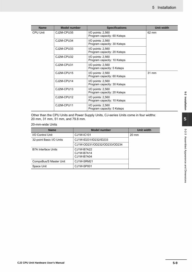
5-9
5 Installation
CJ2 CPU Unit Hardware User’s Manual
5-2 Installation
5
5-2-3 Assem
bled Appearance and D
imensions
Other than the CPU Units and Power Supply Units, CJ-series Units come in four widths: 20 mm, 31 mm, 51 mm, and 79.8 mm.
20-mm-wide Units
CPU Unit CJ2M-CPU35 I/O points: 2,560Program capacity: 60 Ksteps
62 mm
CJ2M-CPU34 I/O points: 2,560Program capacity: 30 Ksteps
CJ2M-CPU33 I/O points: 2,560Program capacity: 20 Ksteps
CJ2M-CPU32 I/O points: 2,560Program capacity: 10 Ksteps
CJ2M-CPU31 I/O points: 2,560Program capacity: 5 Ksteps
CJ2M-CPU15 I/O points: 2,560Program capacity: 60 Ksteps
31 mm
CJ2M-CPU14 I/O points: 2,560Program capacity: 30 Ksteps
CJ2M-CPU13 I/O points: 2,560Program capacity: 20 Ksteps
CJ2M-CPU12 I/O points: 2,560Program capacity: 10 Ksteps
CJ2M-CPU11 I/O points: 2,560Program capacity: 5 Ksteps
Name Model number Unit widthI/O Control Unit CJ1W-IC101 20 mm
32-point Basic I/O Units CJ1W-ID231/ID232/ID233
CJ1W-OD231/OD232/OD233/OD234
B7A Interface Units CJ1W-B7A22CJ1W-B7A14CJ1W-B7A04
CompoBus/S Master Unit CJ1W-SRM21
Space Unit CJ1W-SP001
Name Model number Specifications Unit width
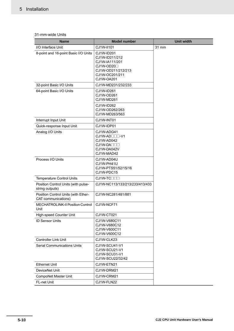
5 Installation
5-10 CJ2 CPU Unit Hardware User’s Manual
31-mm-wide Units
Name Model number Unit widthI/O Interface Unit CJ1W-II101 31 mm
8-point and 16-point Basic I/O Units CJ1W-ID201CJ1W-ID211/212CJ1W-IA111/201CJ1W-OD20@CJ1W-OD211/212/213CJ1W-OC201/211CJ1W-OA201
32-point Basic I/O Units CJ1W-MD231/232/233
64-point Basic I/O Units CJ1W-ID261CJ1W-OD261CJ1W-MD261
CJ1W-ID262CJ1W-OD262/263CJ1W-MD263/563
Interrupt Input Unit CJ1W-INT01
Quick-response Input Unit CJ1W-IDP01
Analog I/O Units CJ1W-ADG41CJ1W-AD@@@-V1CJ1W-AD042CJ1W-DA@@@CJ1W-DA042VCJ1W-MAD42
Process I/O Units CJ1W-AD04UCJ1W-PH41UCJ1W-PTS51/52/15/16CJ1W-PDC15
Temperature Control Units CJ1W-TC@@@
Position Control Units (with pulse-string outputs)
CJ1W-NC113/133/213/233/413/433
Position Control Units (with Ether-CAT communications)
CJ1W-NC281/481/881
MECHATROLINK-II Position Control Unit
CJ1W-NCF71
High-speed Counter Unit CJ1W-CT021
ID Sensor Units CJ1W-V680C11CJ1W-V680C12CJ1W-V600C11CJ1W-V600C12
Controller Link Unit CJ1W-CLK23
Serial Communications Units CJ1W-SCU41-V1CJ1W-SCU21-V1CJ1W-SCU31-V1CJ1W-SCU22/32/42
Ethernet Unit CJ1W-ETN21
DeviceNet Unit CJ1W-DRM21
CompoNet Master Unit CJ1W-CRM21
FL-net Unit CJ1W-FLN22
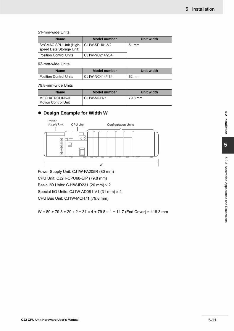
5-11
5 Installation
CJ2 CPU Unit Hardware User’s Manual
5-2 Installation
5
5-2-3 Assem
bled Appearance and D
imensions
51-mm-wide Units
62-mm-wide Units
79.8-mm-wide Units
� Design Example for Width W
Power Supply Unit: CJ1W-PA205R (80 mm)
CPU Unit: CJ2H-CPU68-EIP (79.8 mm)
Basic I/O Units: CJ1W-ID231 (20 mm) × 2
Special I/O Units: CJ1W-AD081-V1 (31 mm) × 4
CPU Bus Unit: CJ1W-MCH71 (79.8 mm)
W = 80 + 79.8 + 20 x 2 + 31 × 4 + 79.8 × 1 + 14.7 (End Cover) = 418.3 mm
Name Model number Unit widthSYSMAC SPU Unit (High-speed Data Storage Unit)
CJ1W-SPU01-V2 51 mm
Position Control Units CJ1W-NC214/234
Name Model number Unit widthPosition Control Units CJ1W-NC414/434 62 mm
Name Model number Unit widthMECHATROLINK-II Motion Control Unit
CJ1W-MCH71 79.8 mm
W
Configuration UnitsCPU UnitPowerSupply Unit

5 Installation
5-12 CJ2 CPU Unit Hardware User’s Manual
The installation height of the CJ-series CPU Rack and Expansion Racks varies from 81.6 to 89.0 mm,depending on the I/O Units that are mounted. When a Programming Device (e.g., CX-Programmer) isconnected, however, even greater height is required. Allow sufficient depth in the control panel contain-ing the PLC.
Installation Dimensions (Unit: mm)
Installation Height
PFP-100N2PFP-100NPFP-50N
A16 mm7.3 mm7.3 mm
DIN Track
27.5
35
27.5
90
A
65
Approx. 100 to 150 mm
81.6 to 89.0 mm

5-13
5 Installation
CJ2 CPU Unit Hardware User’s Manual
5-2 Installation
5
5-2-4 Connecting P
LC C
omponents
The Units that make up a CJ-series PLC can be connected simply by pressing the Units together andlocking the sliders by moving them toward the back of the Units. The End Cover is connected in thesame way to the Unit on the far right side of the PLC.
1 Join the Units so that the connectors fit exactly.
2 The yellow sliders at the top and bottom of each Unit lock the Units together. Move the sliderstoward the back of the Units as shown below until they click into place.
Precautions for Correct UsePrecautions for Correct Use
If the locking tabs are not secured properly, the connectors may become loose and not functionproperly. Be sure to slide the locking tabs until they are securely in place.
5-2-4 Connecting PLC Components
ConnectorHook Hook holes
Slider
Lock
Release
Move the sliders toward the back until they lock into place.

5 Installation
5-14 CJ2 CPU Unit Hardware User’s Manual
3 Attach the End Cover to the Unit on the far right side of the Rack.
● CJ2H CPU Unit
● CJ2M CPU Unit
Additional Information
There is no Backplane for the CJ-series. The PLC is constructed by connecting Units togetherusing the connectors on the sides.
Precautions for Correct UsePrecautions for Correct Use
• Always turn OFF the power supply before connecting Units to each other.• Always turn OFF the power supply to the entire system before replacing a Unit.• A maximum of nine Configuration Units can be connected to a CPU Rack, and a maximum of
ten Configuration Units can be connected to an Expansion Rack. If more than the maximumnumber of Units are connected, a too many I/O points error (fatal error) will occur and the CJ2CPU Unit will not operate in either RUN or MONITOR mode. If this occurs, The I/O OverflowFlag (A401.11) will turn ON and A407.13 to A407.15 (I/O Overflow Details 2) will turn ON.
CPU Rack
Power Supply Unit
CPU Unit (I/O Control Unit) *1I/O Units (10 max.)
End Cover (included with CPU Unit)
*1: Connect the I/O Control Unit directly to the CPU Unit to enable connecting Expansion Racks.
CPU Rack
Power Supply Unit
CPU Unit (I/O Control Unit) *1I/O Units (10 max.)
End Cover (included with CPU Unit)
*1: Connect the I/O Control Unit directly to the CPU Unit to enable connecting Expansion Racks.
*2: Connect the I/O Interface Unit directly to the Power Supply Unit.
Expansion Rack
I/O Interface Unit *2I/O Units (10 max.)
End Cover (included with I/O Interface Unit)
Power Supply Unit

5-15
5 Installation
CJ2 CPU Unit Hardware User’s Manual
5-2 Installation
5
5-2-5 DIN
Track Installation
Use the following procedure to install a CJ-series PLC on DIN Track.
1 Release the pins on the backs of the CJ-series Units.
2 Fit the back of the PLC onto the DIN Track by inserting the top of the track and then pressing inat the bottom of the PLC, as shown below.
3 Lock the pins on the backs of the CJ-series Units.
5-2-5 DIN Track Installation
Release
DIN Track mounting pins
DIN Track
2
1
DIN Track mounting pins

5 Installation
5-16 CJ2 CPU Unit Hardware User’s Manual
4 Install a DIN Track End Plate on each end of the PLC. To install an End Plate, hook the bottomon the bottom of the track, rotate the Plate to hook the top of the Plate on the top of the track,and then tighten the screw to lock the Plate in place.
Use the DIN Track and DIN Track End Plates shown below. Secure each DIN Track inside a controlpanel with at least three screws. • DIN Track
Model numbers: PFP-50N (50 cm), PFP-100N (100 cm), PFP-100N2 (100 cm)
Secure the DIN Track to the control panel using M4 screws separated by 210 mm (6 holes) or less andusing at least 3 screws. The tightening torque is 1.2 N·m.
• PFP-M DIN Track End Plates (2 required)
DIN Track and Accessories
End Plates
2
1
1510
4.5
25 25 2510
25 151000
PFP-100N2 DIN Track
PFP-100N/50N DIN Track
1510
4.5
25 25 2510
25 1
16
1.51
29.2242730 0.3
7.3 0.15
35 0.3 27 0.15
Twenty-eight, 25 × 4.5 oblong holes
1000 (500)*15 (5)*
* PFP-50N dimensions are given in parentheses.

5-17
5 Installation
CJ2 CPU Unit Hardware User’s Manual
5-2 Installation
5
5-2-6 Connecting C
J-series Expansion R
acks
CS/CJ-series I/O Connecting Cables are used to connect the CPU Rack and Expansion Racks.
� CS/CJ-series I/O Connecting Cables
• These connectors are equipped with easy-lock connectors. • Use them to connect the CPU Rack to an Expansion Rack or to connect two Expansion Racks.
• The CJ-series I/O Connecting Cables are used to connect the I/O Control Unit on the CPU Rackto the I/O Interface Unit on an Expansion Rack or to connect the I/O Interface Units on two Expan-sion Racks.
• Install the Racks and select I/O Connecting Cables so that the total length of all I/O ConnectingCables does not exceed 12 m.
• The following diagram shows where each I/O Connecting Cable must be connected on eachRack. The Rack will not operate if the cables aren’t connected properly. (The “up” direction istowards the CPU Unit and “down” is away from the CPU Unit.)
5-2-6 Connecting CJ-series Expansion Racks
Model number Cable lengthCS1W-CN313 0.3 m
CS1W-CN713 0.7 m
CS1W-CN223 2 m
CS1W-CN323 3 m
CS1W-CN523 5 m
CS1W-CN133 10 m
CS1W-CN133B2 12 m
I/O Control Unit
Power Supply Unit
CPU Unit
I/O Interface Unit
Power Supply Unit
CPU Rack
Expansion Rack
Down
Up
Down

5 Installation
5-18 CJ2 CPU Unit Hardware User’s Manual
� Cable ConnectionsThe following diagram shows examples of proper Rack connections. Connect the simple lock con-nectors to the I/O Control Unit on the CJ-series CPU Rack and the I/O Interface Unit on the CJ-series Expansion Rack.
• The top and bottom of the connector are different. Be sure the connector is facing the correctdirection before connecting it.
� Connecting the Simple Locking ConnectorsPress the tabs on the end of the connector and insert the connector until it locks in place. The PLCwill not operate properly if the connector isn’t inserted completely.
To remove the connector, press the tabs and pull on the connector.
Power Supply Unit
CPU Unit I/O Control Unit
I/O Interface Unit
Power Supply Unit
CPU Rack
Expansion Rack
Expansion Rack
I/O Connecting Cable
I/O Connecting CableI/O Interface Unit
Power Supply Unit
I/O Interface Unit
Power Supply Unit
Expansion Rack
I/O Connecting Cable
Total cable length: 12 m max.

5-19
5 Installation
CJ2 CPU Unit Hardware User’s Manual
5-2 Installation
5
5-2-6 Connecting C
J-series Expansion R
acks
Precautions for Correct UsePrecautions for Correct Use
• When using an I/O Connecting Cable with a locking connector, be sure that the connector isfirmly locked in place before using it.
• Always turn OFF the power supply to the PLC before connecting a cable.• An I/O bus error will occur and the PLC will stop if an I/O Connecting Cable's connector sepa-
rates from the Rack. Be sure that the connectors are secure.• A 63-mm hole will be required if the I/O Connecting Cable must pass through a hole when con-
necting an Expansion Rack. • Do not bend the I/O Connecting cable past its natural bending radius or pull in it with excessive
force. • The cables can withstand a pulling force up to 49 N (11 lbs), so be sure that they are not pulled
too forcefully.• The I/O Connecting Cables mustn't be bent too severely. The minimum bending radii are
shown in the following diagram.
• Always attach the cover to the output connector (left side) on the last I/O Interface Unit on thelast Expansion Rack to protect it from dust.
R R = 69 mm min.
Cable outer diameter: 8.6 mm
TUO INII101
CJ1W-II101 I/O Interface Unit
Output connector cover
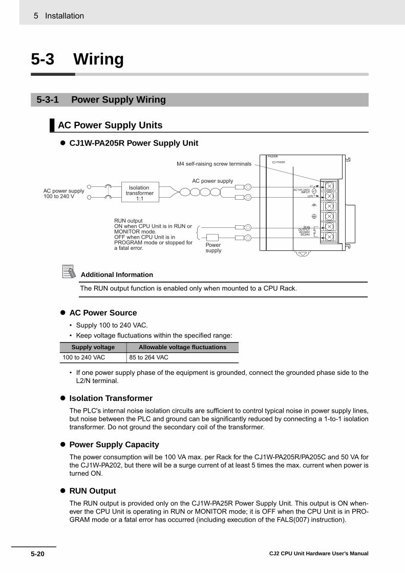
5 Installation
5-20 CJ2 CPU Unit Hardware User’s Manual
5-3 Wiring
� CJ1W-PA205R Power Supply Unit
Additional Information
The RUN output function is enabled only when mounted to a CPU Rack.
� AC Power Source• Supply 100 to 240 VAC.• Keep voltage fluctuations within the specified range:
• If one power supply phase of the equipment is grounded, connect the grounded phase side to theL2/N terminal.
� Isolation TransformerThe PLC's internal noise isolation circuits are sufficient to control typical noise in power supply lines,but noise between the PLC and ground can be significantly reduced by connecting a 1-to-1 isolationtransformer. Do not ground the secondary coil of the transformer.
� Power Supply CapacityThe power consumption will be 100 VA max. per Rack for the CJ1W-PA205R/PA205C and 50 VA forthe CJ1W-PA202, but there will be a surge current of at least 5 times the max. current when power isturned ON.
� RUN OutputThe RUN output is provided only on the CJ1W-PA25R Power Supply Unit. This output is ON when-ever the CPU Unit is operating in RUN or MONITOR mode; it is OFF when the CPU Unit is in PRO-GRAM mode or a fatal error has occurred (including execution of the FALS(007) instruction).
5-3-1 Power Supply Wiring
AC Power Supply Units
Supply voltage Allowable voltage fluctuations100 to 240 VAC 85 to 264 VAC
POWER
PA205R
DC24VAC240V
OUTPUTRUN
INPUTAC100-240V
L2/N
L1Isolationtransformer
1:1AC power supply100 to 240 V
AC power supply
M4 self-raising screw terminals
Power supply
RUN outputON when CPU Unit is in RUN or MONITOR mode. OFF when CPU Unit is in PROGRAM mode or stopped for a fatal error.
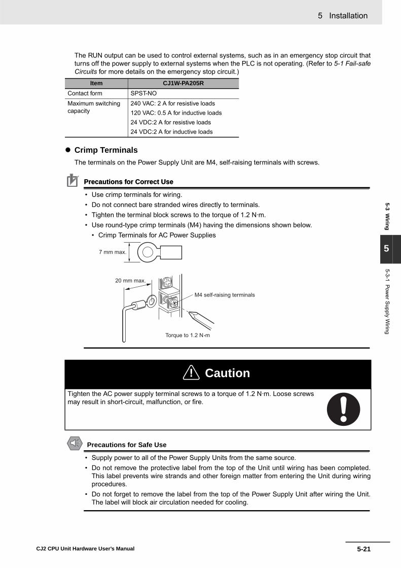
5-21
5 Installation
CJ2 CPU Unit Hardware User’s Manual
5-3 Wiring
5
5-3-1 Power S
upply Wiring
The RUN output can be used to control external systems, such as in an emergency stop circuit thatturns off the power supply to external systems when the PLC is not operating. (Refer to 5-1 Fail-safeCircuits for more details on the emergency stop circuit.)
� Crimp TerminalsThe terminals on the Power Supply Unit are M4, self-raising terminals with screws.
Precautions for Correct UsePrecautions for Correct Use
• Use crimp terminals for wiring.• Do not connect bare stranded wires directly to terminals.• Tighten the terminal block screws to the torque of 1.2 N·m.• Use round-type crimp terminals (M4) having the dimensions shown below.
• Crimp Terminals for AC Power Supplies
Precautions for Safe Use
• Supply power to all of the Power Supply Units from the same source.• Do not remove the protective label from the top of the Unit until wiring has been completed.
This label prevents wire strands and other foreign matter from entering the Unit during wiringprocedures.
• Do not forget to remove the label from the top of the Power Supply Unit after wiring the Unit.The label will block air circulation needed for cooling.
Item CJ1W-PA205RContact form SPST-NO
Maximum switching capacity
240 VAC: 2 A for resistive loads120 VAC: 0.5 A for inductive loads24 VDC:2 A for resistive loads24 VDC:2 A for inductive loads
! CautionTighten the AC power supply terminal screws to a torque of 1.2 N·m. Loose screwsmay result in short-circuit, malfunction, or fire.
7 mm max.
Torque to 1.2 N •m
20 mm max.
M4 self-raising terminals

5 Installation
5-22 CJ2 CPU Unit Hardware User’s Manual
� CJ1W-PD025 Power Supply Unit
� DC Power SourceSupply 24 VDC. Keep voltage fluctuations within the specified range.
� Power Supply CapacityThe maximum power consumption is 50 W (CJ1W-PD025)/35 W (CJ1W-PD022) per Rack, but therewill be a surge current of about five times that level when the power is turned ON.
� Precautions when Using CJ1W-PD022 Non-insulated Power Supply Units
DC Power Supplies
Model Allowable voltage fluctuation rangeCJ1W-PD025 19.2 to 28.8 VDC (±20%)
CJ1W-PD022 21.6 to 26.4 VDC (±10%)
! CautionWhen connecting a personal computers or other peripheral devices to a PLC to which a non-insulated Power Supply Unit (CJ1W-PD022) is mounted, either ground the 0 V side of the external power supply or do not ground the external power supply at all ground. A short-cir-cuit will occur in the external power supply if incorrect grounding methods are used. Never ground the 24 V side, as shown below.
Wiring in Which the 24-V Power Supply Will Short
POWER
PD025
DC24V+INPUT
NC
NC
DC power supply
Screw terminals (M4 head with self-raising pressure plate)
24 V
0 V
FG FG
0 V 0 V
CPU Unit
Non-insulatedDC power supply
Power Supply Unit
Peripheral cable
Peripheral device (e.g., personal computer)

5-23
5 Installation
CJ2 CPU Unit Hardware User’s Manual
5-3 Wiring
5
5-3-1 Power S
upply Wiring
� Crimp TerminalsThe terminals on the Power Supply Unit are M4, self-raising terminals with screws.
Precautions for Correct UsePrecautions for Correct Use
• Use crimp terminals for wiring.• Do not connect bare stranded wires directly to terminals.• Tighten the terminal block screws to the torque of 1.2 N·m.• Use crimp terminals (M4) having the dimensions shown below.
Precautions for Safe Use
• Be sure not to reverse the positive and negative leads when wiring the power supply terminals.• Supply power to all of the Power Supply Units from the same source.• Do not remove the protective label from the top of the Unit until wiring has been completed.
This label prevents wire strands and other foreign matter from entering the Unit during wiringprocedures.
• Do not forget to remove the label from the top of the Power Supply Unit after wiring the Unit.The label will block air circulation needed for cooling.
• To help prevent electrical shock, ground the ground terminal (GR: ) with a ground resistance ofless than 100 Ω using a 14-gauge wire (minimum cross-sectional area of 2 mm2).
• The line ground terminal (LG: ) is a noise-filtered neutral terminal. If noise is a significant source oferrors or electrical shocks are a problem, connect the line ground terminal to the ground terminal andground both with a ground resistance of less than 100 Ω.
• The ground wire should not be more than 20 m long.• The CJ-series PLCs are designed to be mounted so that they are isolated (separated) from the
mounting surface to protect them from the effects of noise in the installation environment (e.g., thecontrol panel).
• Do not share the PLC’s ground with other equipment or ground the PLC to the metal structure of abuilding. The configuration shown in the following diagram may worsen operation.
Grounding
7 mm max. 7 mm max.
Crimp Terminals for DC Power Supplies
POWER
PA205R
DC24VAC240V
OUTPUTRUN
INPUTAC100-240V
L2/N
L1
LG (Noise-filter neutral terminal)Ground this terminal to less than 100 Ω to improve noise resistance and prevent electric shock.
GR (Ground terminal)Ground this terminal to less than 100 Ωto prevent electric shock.
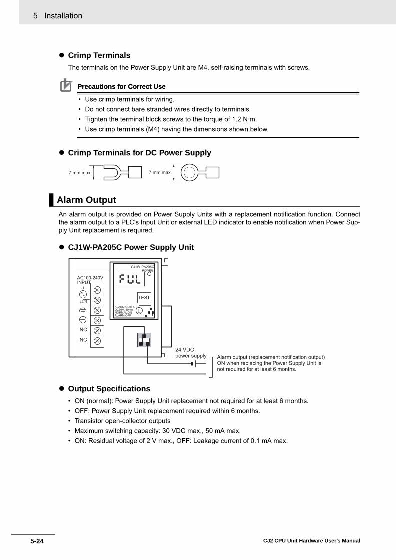
5 Installation
5-24 CJ2 CPU Unit Hardware User’s Manual
� Crimp TerminalsThe terminals on the Power Supply Unit are M4, self-raising terminals with screws.
Precautions for Correct UsePrecautions for Correct Use
• Use crimp terminals for wiring.• Do not connect bare stranded wires directly to terminals.• Tighten the terminal block screws to the torque of 1.2 N·m.• Use crimp terminals (M4) having the dimensions shown below.
� Crimp Terminals for DC Power Supply
An alarm output is provided on Power Supply Units with a replacement notification function. Connectthe alarm output to a PLC's Input Unit or external LED indicator to enable notification when Power Sup-ply Unit replacement is required.
� CJ1W-PA205C Power Supply Unit
� Output Specifications• ON (normal): Power Supply Unit replacement not required for at least 6 months.• OFF: Power Supply Unit replacement required within 6 months. • Transistor open-collector outputs• Maximum switching capacity: 30 VDC max., 50 mA max.• ON: Residual voltage of 2 V max., OFF: Leakage current of 0.1 mA max.
Alarm Output
7 mm max. 7 mm max.
AC100-240VINPUT
NC
NC
L1
L2/N
CJ1W-PA205CPOWER
TEST
ALARM OUTPUTDC30V, 50mANORMAL:ONALARM:OFF
L
Alarm output (replacement notification output)ON when replacing the Power Supply Unit is not required for at least 6 months.
24 VDC power supply

5-25
5 Installation
CJ2 CPU Unit Hardware User’s Manual
5-3 Wiring
5
5-3-1 Power S
upply Wiring
� WiringThe following wire gauges are recommended.
� PLC Input Unit Wiring ExampleConnect the positive terminals of the 24-VDC power supply to the Input Unit common (COM) termi-nals.
Connect the negative terminal of the 24-VDC power supply to the Input Unit common (COM) termi-nal.
Recommended wire size Use
Pushingstrength (clamp-
ing operation)
Pulling strength (holding force)
Length of stripped section
AWG 22 to 18 (0.32 to 0.82 mm2)
Connecting to PLC terminal block models
30 N max. 30 N min. 7 to 10 mm
AWG 28 to 24 (0.08 to 0.2 mm2)
Connecting to PLC connector models
10 N min.
AC100-240VINPUT
NC
NC
L1
L2/N
CJ1W-PA205CPOWER
TEST
ALARM OUTPUTDC30V, 50mANORMAL:ONALARM OFF
L
IN0
IN(N)
IN(N+1)
COM
CPU UnitCJ1W-PA205CIN UnitCJ1W-ID2@@
24-VDC power supply
IN0
IN(N)
IN(N+1)
COM
AC100-240VINPUT
NC
NC
L1
L2/N
CJ1W-PA205CPOWER
TEST
ALARM OUTPUTDC30V, 50mANORMAL:ONALARM OFF
L
CJ1W-PA205C CPU UnitIN UnitCJ1W-ID2@@
24-VDC power supply

5 Installation
5-26 CJ2 CPU Unit Hardware User’s Manual
� External Display Device Connection ExampleThe alarm output (replacement notification output) is an NC contact. Therefore, wire the alarm out-put using an NC contact or other means to turn ON an error indicator or LED display as shown in thefollowing diagram.
Note The OL display will also light if the PLC's power supply fails.
Precautions for Safe Use
• Separate the alarm output cables from power lines and high-voltage lines.• Do not apply a voltage or connect a load to the alarm output that exceeds the rated voltage or
load.
AC100-240VINPUT
NC
NC
L1
L2/N
CJ1W-PA205CPOWER
TEST
ALARM OUTPUTDC30V, 50mANORMAL:ONALARM OFF
L
OL24-VDC power supply
Relay (NC contacts)
Power supply
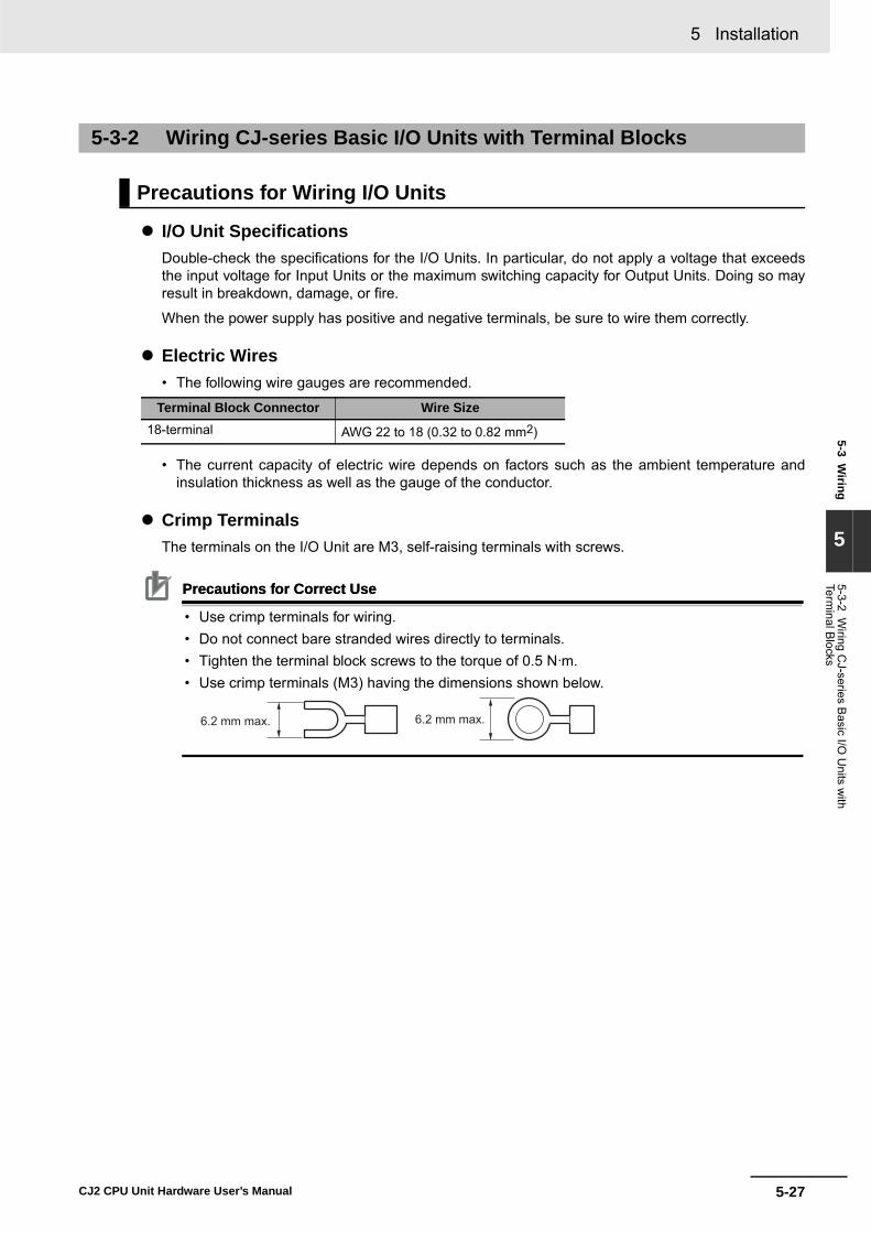
5-27
5 Installation
CJ2 CPU Unit Hardware User’s Manual
5-3 Wiring
5
5-3-2 Wiring C
J-series Basic I/O
Units w
ith Term
inal Blocks
� I/O Unit SpecificationsDouble-check the specifications for the I/O Units. In particular, do not apply a voltage that exceedsthe input voltage for Input Units or the maximum switching capacity for Output Units. Doing so mayresult in breakdown, damage, or fire.
When the power supply has positive and negative terminals, be sure to wire them correctly.
� Electric Wires• The following wire gauges are recommended.
• The current capacity of electric wire depends on factors such as the ambient temperature andinsulation thickness as well as the gauge of the conductor.
� Crimp TerminalsThe terminals on the I/O Unit are M3, self-raising terminals with screws.
Precautions for Correct UsePrecautions for Correct Use
• Use crimp terminals for wiring.• Do not connect bare stranded wires directly to terminals.• Tighten the terminal block screws to the torque of 0.5 N·m.• Use crimp terminals (M3) having the dimensions shown below.
5-3-2 Wiring CJ-series Basic I/O Units with Terminal Blocks
Precautions for Wiring I/O Units
Terminal Block Connector Wire Size18-terminal AWG 22 to 18 (0.32 to 0.82 mm2)
6.2 mm max. 6.2 mm max.

5 Installation
5-28 CJ2 CPU Unit Hardware User’s Manual
� Wiring• Make sure that all Units are connected properly. • Do not remove the protective label from the top of the Unit until wiring has been completed.• This label prevents wire strands and other foreign matter from entering the Unit during wiring pro-
cedures.• Remove the label after wiring has been completed to allow air circulation needed for cooling.
• Wire the Units so that they can be easily replaced. • Make sure that the I/O indicators are not covered by the wiring.• Do not place the wiring for I/O Units in the same duct or raceway as power lines. Inductive noise
can cause errors in operation.• Tighten the terminal screws to the torque of 0.5 N·m.
� Terminal Blocks• The I/O Units are equipped with removable terminal blocks. The lead wires do not have to be
removed from the terminal block to remove it from an I/O Unit.• After you complete wiring, check to see if the terminal block is securely locked.
OD2110 1 2 3 4 5 6 78 9 10 11 12 13 14 15
OD2110 1 2 3 4 5 6 78 9 10 11 12 13 14 15
After wiringDuring wiring
Remove the label.
17.5 mm
Screw (M3 screw with self-raising pressure plate)
112DO0 1 2 3 4 5 6 78 9 10 11 12 13 14 15
Terminal block lever
CJ-series Basic I/O Unit

5-29
5 Installation
CJ2 CPU Unit Hardware User’s Manual
5-3 Wiring
5
5-3-3 Wiring B
asic I/O U
nits with C
onnectors
This section describes wiring for CJ-series Basic I/O Units with connectors (32- and 64-point Units).Depending on the connector, the following methods are used to connect these Units to external I/Odevices.• Use an OMRON Connecting Cable (equipped with a special connector) to connect to a Terminal
Block or Relay Terminal.• Use a special connector and user-provided cable.
Precautions for Safe Use
• Be sure not to apply a voltage that exceeds the input voltage for Input Units or the maximumswitching capacity for Output Units.
• When the power supply has positive and negative terminals, be sure to wire them correctly.Loads connected to Output Units may malfunction if the polarity is reversed.
• Use reinforced insulation or double insulation on the DC power supply connected to DC I/OUnits when required by EC Directives (low voltage).
• When connecting the connector to the I/O Unit, tighten the connector screws to a torque of0.2 N·m.
• Turn ON the power after checking the connector's wiring. • Do not pull the cable. Doing so will damage the cable.• Bending the cable too sharply can damage or break wiring in the cable.
Additional Information
CJ-series Basic I/O Units with 32 or 64 points and Fujitsu connectors have the same connectorpin allocations as the C200H High-density I/O Units and CS-series I/O Units with connectors tomake them compatible.
For details on using OMRON Connecting Cables equipped with special connectors to connect Basic I/OUnits with connectors to OMRON Connector-Terminal Block Conversion Units or I/O Relay Terminals,refer to A-1-4 Connecting Connector-Terminal Block Conversion Units and I/O Relay Terminals.
5-3-3 Wiring Basic I/O Units with Connectors
Connecting to a Connector-Terminal Block Conversion Unit or I/O Relay Terminal
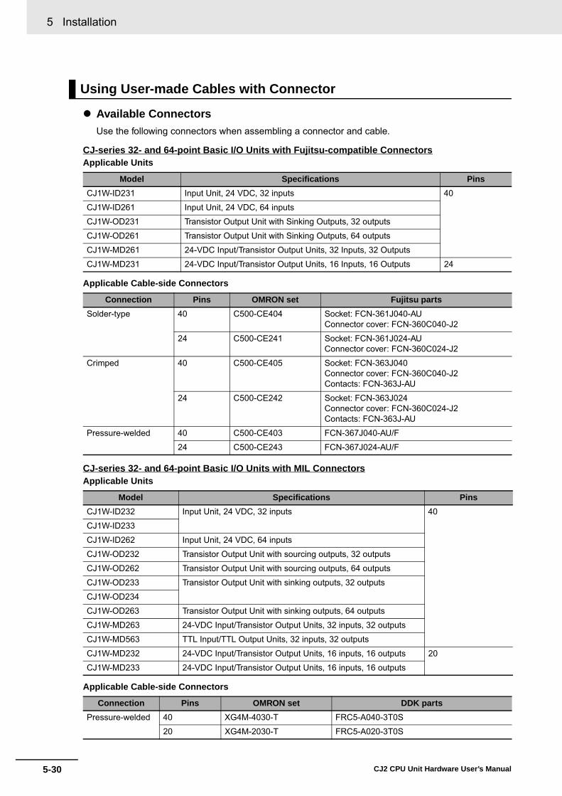
5 Installation
5-30 CJ2 CPU Unit Hardware User’s Manual
� Available ConnectorsUse the following connectors when assembling a connector and cable.
CJ-series 32- and 64-point Basic I/O Units with Fujitsu-compatible Connectors
CJ-series 32- and 64-point Basic I/O Units with MIL Connectors
Using User-made Cables with Connector
Applicable Units
Model Specifications PinsCJ1W-ID231 Input Unit, 24 VDC, 32 inputs 40
CJ1W-ID261 Input Unit, 24 VDC, 64 inputs
CJ1W-OD231 Transistor Output Unit with Sinking Outputs, 32 outputs
CJ1W-OD261 Transistor Output Unit with Sinking Outputs, 64 outputs
CJ1W-MD261 24-VDC Input/Transistor Output Units, 32 Inputs, 32 Outputs
CJ1W-MD231 24-VDC Input/Transistor Output Units, 16 Inputs, 16 Outputs 24
Applicable Cable-side Connectors
Connection Pins OMRON set Fujitsu partsSolder-type 40 C500-CE404 Socket: FCN-361J040-AU
Connector cover: FCN-360C040-J2
24 C500-CE241 Socket: FCN-361J024-AUConnector cover: FCN-360C024-J2
Crimped 40 C500-CE405 Socket: FCN-363J040Connector cover: FCN-360C040-J2Contacts: FCN-363J-AU
24 C500-CE242 Socket: FCN-363J024Connector cover: FCN-360C024-J2Contacts: FCN-363J-AU
Pressure-welded 40 C500-CE403 FCN-367J040-AU/F
24 C500-CE243 FCN-367J024-AU/F
Applicable Units
Model Specifications PinsCJ1W-ID232 Input Unit, 24 VDC, 32 inputs 40
CJ1W-ID233
CJ1W-ID262 Input Unit, 24 VDC, 64 inputs
CJ1W-OD232 Transistor Output Unit with sourcing outputs, 32 outputs
CJ1W-OD262 Transistor Output Unit with sourcing outputs, 64 outputs
CJ1W-OD233 Transistor Output Unit with sinking outputs, 32 outputs
CJ1W-OD234
CJ1W-OD263 Transistor Output Unit with sinking outputs, 64 outputs
CJ1W-MD263 24-VDC Input/Transistor Output Units, 32 inputs, 32 outputs
CJ1W-MD563 TTL Input/TTL Output Units, 32 inputs, 32 outputs
CJ1W-MD232 24-VDC Input/Transistor Output Units, 16 inputs, 16 outputs 20
CJ1W-MD233 24-VDC Input/Transistor Output Units, 16 inputs, 16 outputs
Applicable Cable-side Connectors
Connection Pins OMRON set DDK partsPressure-welded 40 XG4M-4030-T FRC5-A040-3T0S
20 XG4M-2030-T FRC5-A020-3T0S
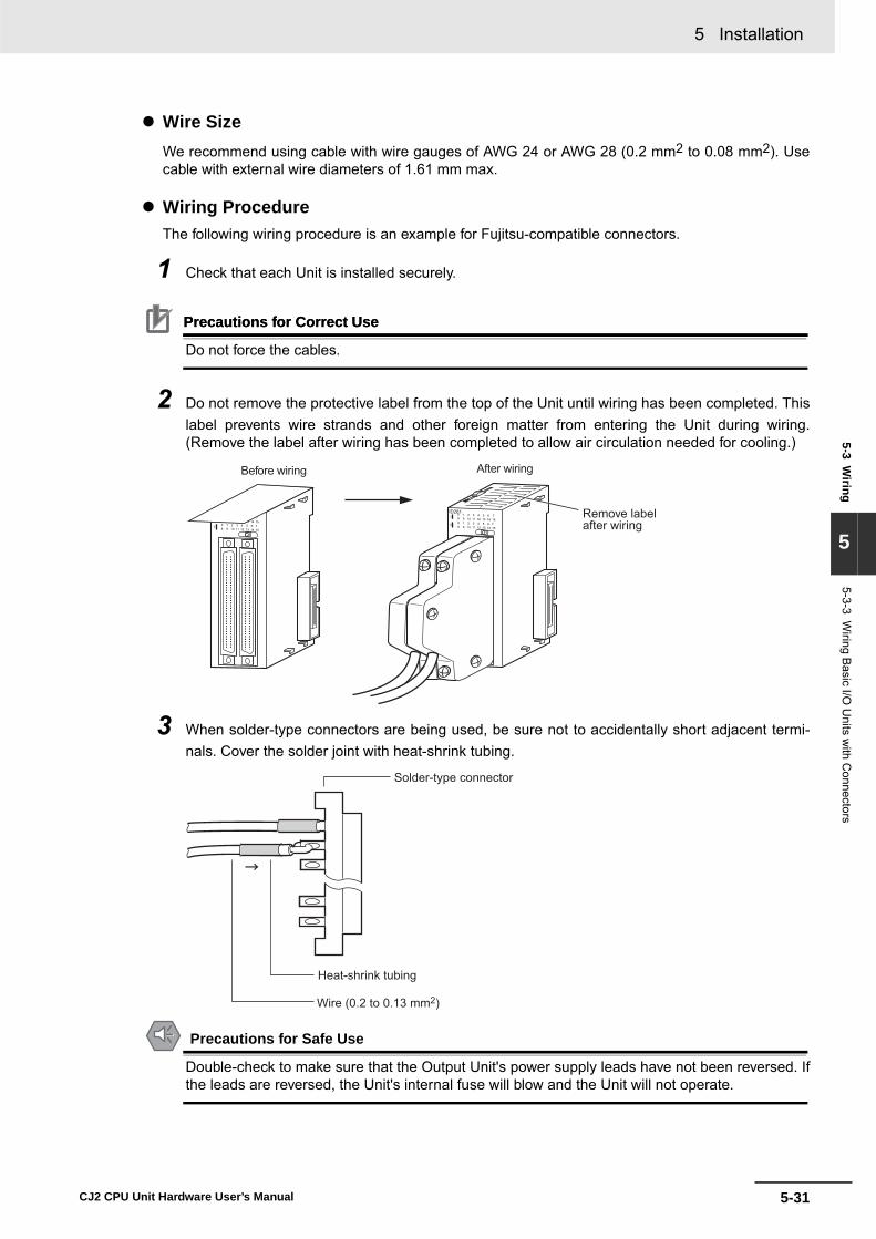
5-31
5 Installation
CJ2 CPU Unit Hardware User’s Manual
5-3 Wiring
5
5-3-3 Wiring B
asic I/O U
nits with C
onnectors
� Wire SizeWe recommend using cable with wire gauges of AWG 24 or AWG 28 (0.2 mm2 to 0.08 mm2). Usecable with external wire diameters of 1.61 mm max.
� Wiring ProcedureThe following wiring procedure is an example for Fujitsu-compatible connectors.
1 Check that each Unit is installed securely.
Precautions for Correct UsePrecautions for Correct Use
Do not force the cables.
2 Do not remove the protective label from the top of the Unit until wiring has been completed. Thislabel prevents wire strands and other foreign matter from entering the Unit during wiring.(Remove the label after wiring has been completed to allow air circulation needed for cooling.)
3 When solder-type connectors are being used, be sure not to accidentally short adjacent termi-nals. Cover the solder joint with heat-shrink tubing.
Precautions for Safe Use
Double-check to make sure that the Output Unit's power supply leads have not been reversed. Ifthe leads are reversed, the Unit's internal fuse will blow and the Unit will not operate.
0 1 2 3 4 5 6 78 9 12 13 14 1510 110 1 2 3 4 5 6 78 9 12 13 14 1510 11
I
II
ID2610 1 2 3 4 5 6 78 9 12 13 14 1510 110 1 2 3 4 5 6 78 9 12 13 14 1510 11
I
II
ID261
Before wiring After wiring
Remove label after wiring
Solder-type connector
Heat-shrink tubing
Wire (0.2 to 0.13 mm2)

5 Installation
5-32 CJ2 CPU Unit Hardware User’s Manual
4 Assemble the connector (purchased separately).
5 Insert the wired connector.
6 Remove the protective label after wiring has been completed to allow air circulation needed forcooling.
Tighten the connector lock screws to a torque of 0.2 N·m.
Connector cover Small screws (3)
Socket
Nuts (3)
Small screws (2)
Connector lock screws
Cable bracket
Nuts (2)
0 1 2 3 4 5 6 78 9 12 13 14 1510 110 1 2 3 4 5 6 78 9 12 13 14 1510 11
I
II
ID261
Connector
ConnectorBasic I/O Unit
Basic I/O Unit
0 1 2 3 4 5 6 78 9 12 13 14 1510 110 1 2 3 4 5 6 78 9 12 13 14 1510 11
I
II
ID261
After wiring
Remove label after wiring.Connector lock screws

5-33
5 Installation
CJ2 CPU Unit Hardware User’s Manual
5-3 Wiring
5
5-3-4 Connecting to C
onnector-Terminal B
lock C
onversion Units or I/O
Relay Term
inals
OMRON Connecting Cable can be used to connect Basic I/O Units with Connectors to OMRON Con-nector-Terminal Block Conversion Units or to OMRON I/O Relay Terminals. For details, refer to A-1-4Connecting Connector-Terminal Block Conversion Units and I/O Relay Terminals.
� Connection Examples
5-3-4 Connecting to Connector-Terminal Block Conversion Units or I/O Relay Terminals
Connector-Terminal Block Conversion Unit I/O Relay Terminals
Connector-Terminal Block Conversion Unit
40 or 60 terminals
Basic I/O Unit
Connecting Cable
I/O Relay Terminal
Connecting Cable
Basic I/O Unit

5 Installation
5-34 CJ2 CPU Unit Hardware User’s Manual
Use the following information for reference when selecting or connecting input devices.
� DC Input UnitsThe following types of DC input devices can be connected.
• The circuit below should NOT be used for I/O devices having a voltage output.
5-3-5 Connecting I/O Devices
Input Devices
COM
Output
Contact output
Two-wire DC output
NPN open-collector output
DC Input Unit
SensorPowerSupply
IN
SensorPowerSupply
COM
DC Input UnitIN
COM
DC Input UnitIN
COM
DC Input UnitIN
0 V7 mA
COM
NPN current output
PNP current output
Voltage output
Currentregulator
INDC Input Unit
SensorPowerSupply
SensorPowerSupply
DC Input Unit
COM
INSensorPowerSupply
0 V7 mA
Output
0 V7 mA
Output
0 V
Output
0 V COM
Voltage output SensorPower Supply
INOutput
DC Input Unit

5-35
5 Installation
CJ2 CPU Unit Hardware User’s Manual
5-3 Wiring
5
5-3-5 Connecting I/O
Devices
� AC Input Units
Precautions for Safe Use
When using a reed switch as the input contact for an AC Input Unit, use a switch with an allow-able current of 1 A or greater. If reed switches with smaller allowable currents are used, the con-tacts may fuse due to surge currents.
�� Precautions when Connecting a Two-wire DC SensorWhen using a two-wire sensor with a 12-VDC or 24-VDC input device, check that the following con-ditions have been met. Failure to meet these conditions may result in operating errors.• Relation between voltage when the PLC is ON and the sensor residual voltage:
VON ≤ VCC − VR
• Relation between voltage when the PLC is ON and sensor control output (load current):IOUT (min) ≤ ION ≤ IOUT (max.)ION = (VCC − VR − 1.5 [PLC internal residual voltage])/RIN
When ION is smaller than IOUT (min), connect a bleeder resistor R. The bleeder resistor constantcan be calculated as follows:R ≤ (VCC − VR)/(IOUT (min.) − ION)Power W ≥ (VCC − VR)2/R × 4 [allowable margin]VCC: Power voltageVR: Sensor output residual currentION: PLC ON currentIOUT: Sensor control current (load current)RIN: PLC input impedance
COM
IN
AC Input Unit
Contact output
AC Switching
Proximity switch maincircuit
COM
INAC Input Unit

5 Installation
5-36 CJ2 CPU Unit Hardware User’s Manual
• Relation between current when the PLC is OFF and sensor leakage current:IOFF ≥ IleakConnect a bleeder resistor if Ileak is greater than IOFF. Use the following equation to calculate thebleeder resistance constant.R ≤ (RIN × VOFF)/(Ileak × RIN − VOFF)Power W ≥ (VCC − VR)2/R × 4 [allowable margin]
• Precautions on Sensor Surge CurrentAn incorrect input may occur if a sensor is turned ON after the PLC has started up to the pointwhere inputs are possible. Determine the time required for sensor operation to stabilize after thesensor is turned ON and take appropriate measures, such as inserting into the program a timerdelay after turning ON the sensor.
� ExampleIn this example, the sensor's power supply voltage is used as the input to CIO 000000 and a 100-mstimer delay (the time required for an OMRON Proximity Sensor to stabilize) is created in the pro-gram. After the Completion Flag for the timer turns ON, the sensor input on CIO 000001 will causeoutput bit CIO 000100 to turn ON.
VR R
VCC
RIN
VCC:VON:VOFF:ION:IOFF:RIN:
VR:IOUT:Ileak:R:
Sensor output residual currentSensor control current (load current)Sensor leakage currentBleeder resistance
Power voltagePLC ON voltagePLC OFF voltagePLC ON currentPLC OFF currentPLC input impedance
Two-wire sensor
DC Input Unit
TIM
0000
#0001
000000
TIM0000 000001000100

5-37
5 Installation
CJ2 CPU Unit Hardware User’s Manual
5-3 Wiring
5
5-3-6 Wiring w
ith Ethernet C
able (CJ2H
-C
PU
6@-EIP
only)
� Output Short-circuit ProtectionIf a load connected to the output terminals is short-circuited, output components and the printed cir-cuit boards may be damaged. To guard against this, incorporate a fuse in the external circuit. Use afuse with a capacity of about twice the rated output.
� Transistor Output Residual VoltageA TTL circuit cannot be connected directly to a transistor output because of the transistor's residualvoltage. It is necessary to connect a pull-up resistor and a CMOS IC between the two.
� Output Surge CurrentWhen connecting a transistor or triac output to an output device having a high surge current (suchas an incandescent lamp), steps must be taken to avoid damage to the transistor or triac. Use eitherof the following methods to reduce the surge current.
Output Wiring Precautions
OUT
R
COM
L+
OUTR
COM
L+
Method 1
CS/CJ-seriesPLC
CS/CJ-seriesPLC
Add a resistor that draws about 1/3 of the current consumed by the bulb.
Method 2
Add a control resistor as shown in the following diagram.

5 Installation
5-38 CJ2 CPU Unit Hardware User’s Manual
Observe the following precautions when using the built-in EtherNet/IP port on the CJ2H-CPU6@-EIP orCJ2M-CPU3@.
� Basic Installation Precautions• Take the greatest care when installing the Ethernet System, being sure to follow ISO 8802-3 spec-
ifications. You must obtain a copy of these specifications and be sure you understand them beforeattempting to install an Ethernet System.
• Unless you are already experienced in installing communications systems, we strongly recom-mend that you employ a professional to install your system.
• Do not install Ethernet equipment near sources of noise. If a noisy environment is unavoidable,take adequate measures against noise interference, such as installing network components ingrounded metal cases or using optical cable in the system.
• When installing an EtherNet/IP network that combines an information system with the control sys-tem, and the communications load may be heavy due to tag data links, we recommend configur-ing the network so that the load does not affect communications. For example, install the tag datalinks in a segment that is separate from the information network.
� Precautions on Laying Twisted-pair Cable• Noise resistance may be reduced by ground loops, which can occur due to improper shield con-
nections and grounding. Ground the shield at one location, as shown in the following diagram.• Do not connect the connector shield at the CPU Unit.• If a cable connects two hubs, connect the shields at only one end.
• Press the cable connector in firmly until it locks into place at both the switching hub and the CPUUnit.
• Do not lay the twisted-pair cable together with high-voltage lines.• Do not lay the twisted-pair cable near devices that generate noise.• Do not lay the twisted-pair cable in locations subject to high temperatures or high humidity.• Do not lay the twisted-pair cable in locations subject to excessive dirt and dust or to oil mist or
other contaminants.
5-3-6 Connecting through an Ethernet Cable (CJ2H-CPU6@-EIP and CJ2M-CPU3@ Only)
Precautions
Hub HubConnector Connector Connector
Connector
Connector Connector
GR GR
Connect shield.
Do not connect shield.
STP
(Shield)
STP
(Shield)
STP
(Shield)
EIPUnit
PowerSupply
Unit
GRterminal
Connector
EIPUnit
PowerSupply
Unit
GRterminal

5-39
5 Installation
CJ2 CPU Unit Hardware User’s Manual
5-3 Wiring
5
5-3-6 Connecting through an Ethernet C
able (C
J2H-C
PU
6@-E
IP and C
J2M-C
PU
3@ O
nly)
The following standards and specifications apply to the connectors for the Ethernet twisted-pair cable.• Electrical specifications: Conform to IEEE802.3 standards.• Connector structure: RJ45 8-pin Modular Connector (Conforms to ISO 8877)
Precautions for Correct UsePrecautions for Correct Use
• Turn OFF the PLC's power supply before connecting or disconnecting twisted-pair cable.• Allow enough space for the bending radius of the twisted-pair cable as shown in below.
1 Lay the twisted-pair cable.
2 Connect the cable to the switching hub. Be sure to press in the cable until it locks into place.
Ethernet Connectors
Connector pin Signal name Abbr. Signal direction1 Transmission data + TD+ Output
2 Transmission data − TD− Output
3 Reception data + RD+ Input
4 Not used. --- ---
5 Not used. --- ---
6 Reception data − RD− Input
7 Not used. --- ---
8 Not used. --- ---
Hood Frame ground FG ---
Connecting the Cable
35 mm

5 Installation
5-40 CJ2 CPU Unit Hardware User’s Manual
3 Connect the twisted-pair cable to the connector on the built-in EtherNet/IP port at the CPU Unit.Be sure to press the connectors at both the switching hub end and Ethernet end until they lockinto place.
Built-in EtherNet/IP port
RJ45 Modular Connector

5-41
5 Installation
CJ2 CPU Unit Hardware User’s Manual
5-4 Control Panel Installation
5
5-4-1 Temperature
5-4 Control Panel Installation
To ensure system reliability and safety, the system must be designed and configured according to theinstallation environment (temperature, humidity, vibration, shock, corrosive gases, overcurrent, noise,etc.).
Panels have been reduced in size due to space-saving and miniaturization in devices and systems, andthe temperature inside the panel may be at least 10 to 15°C higher than outside the panel. Implementthe following measures against overheating at the installation site and in the panel, and allow a suffi-cient margin for the temperature.
Use the following cooling methods as required, taking into account the ambient temperature and theamount of heating inside the panel.
� Natural CoolingNatural cooling relies on natural ventilation through slits in the panel, rather than using coolingdevices such as fans or coolers. When using this method, observe the following points.• Do not install the PLC at the top of the panel, where hot air tends to stagnate. • To provide ventilation space above and below the PLC, leave sufficient distance from other
devices, wiring ducts, etc.• Do not mount the Units in the wrong direction (e.g., vertically or upside down). Doing so may
cause abnormal heating in the PLC. • Do not install heat-generating equipment, such as heaters, transformers, and devices with high
resistance, directly above the panel.• Do not install the PLC in a location exposed to direct sunlight.
� Forced Ventilation (by Fan at Top of Panel)
5-4-1 Temperature
High Temperatures
PLC
PLC
Natural Cooling
PLC
PLC
Air filter
Fan
Forced Ventilation Method

5 Installation
5-42 CJ2 CPU Unit Hardware User’s Manual
� Forced Air Circulation (by Fan in Closed Panel)
� Room Cooling (Cooling the Entire Room Where the Control Panel Is Located)
The PLC will not start normally if the temperature is below 0°C when the power is turned ON. Maintainan air temperature of at least approximately 5°C inside the panel, by implementing measures such asinstalling a low-capacity space heater in the panel. Alternatively, leave the PLC power ON to keep thePLC warm.
Low Temperatures
FanPLC
PLC
Forced Air Circulation
Room Cooling
Cooler
Control panel
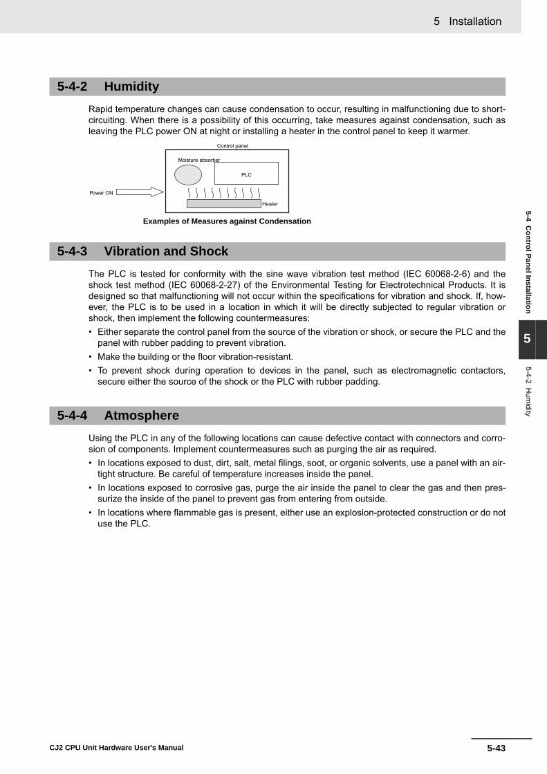
5-43
5 Installation
CJ2 CPU Unit Hardware User’s Manual
5-4 Control Panel Installation
5
5-4-2 Hum
idity
Rapid temperature changes can cause condensation to occur, resulting in malfunctioning due to short-circuiting. When there is a possibility of this occurring, take measures against condensation, such asleaving the PLC power ON at night or installing a heater in the control panel to keep it warmer.
The PLC is tested for conformity with the sine wave vibration test method (IEC 60068-2-6) and theshock test method (IEC 60068-2-27) of the Environmental Testing for Electrotechnical Products. It isdesigned so that malfunctioning will not occur within the specifications for vibration and shock. If, how-ever, the PLC is to be used in a location in which it will be directly subjected to regular vibration orshock, then implement the following countermeasures:• Either separate the control panel from the source of the vibration or shock, or secure the PLC and the
panel with rubber padding to prevent vibration.• Make the building or the floor vibration-resistant.• To prevent shock during operation to devices in the panel, such as electromagnetic contactors,
secure either the source of the shock or the PLC with rubber padding.
Using the PLC in any of the following locations can cause defective contact with connectors and corro-sion of components. Implement countermeasures such as purging the air as required. • In locations exposed to dust, dirt, salt, metal filings, soot, or organic solvents, use a panel with an air-
tight structure. Be careful of temperature increases inside the panel.• In locations exposed to corrosive gas, purge the air inside the panel to clear the gas and then pres-
surize the inside of the panel to prevent gas from entering from outside.• In locations where flammable gas is present, either use an explosion-protected construction or do not
use the PLC.
5-4-2 Humidity
5-4-3 Vibration and Shock
5-4-4 Atmosphere
Moisture absorber
Power ON
Control panel
PLC
Heater
Examples of Measures against Condensation

5 Installation
5-44 CJ2 CPU Unit Hardware User’s Manual
When installing or wiring devices, make sure that there will be no danger to people and that noise willnot interfere with electrical signals.
Install the PLC as far away as possible from high-voltage (600 V or higher) and power devices to ensuresafe operation and maintenance.
Observe the following points.• Place a Unit that does not generate much noise next to the CPU Unit, such as an Input Unit or Com-
munications Unit.• The coils and contacts in electromagnetic contactors and relays in an external circuit are sources of
noise. Locate them at least 100 mm away from the PLC.
5-4-5 Electrical Environment
PLC Installation Location
Arrangement of PLC and Units
Example of Recommended Equipment Arrangement
PLC
Control panel Control panel High-voltage power panel
Examples of Equipment Arrangement in Panel with High-voltage Devices
Example of Poor Equipment Arrangement
PLC
Control panel Control panel High-voltage power panel
OK
NG
Pow
er S
uppl
y U
nit
Com
mun
icatio
ns U
nit
CP
U
DC
Uni
t
DC
Uni
t
AC U
nit
AC U
nit
DC I/O device
AC I/O device
Terminal block
Example of Arrangement in Panel
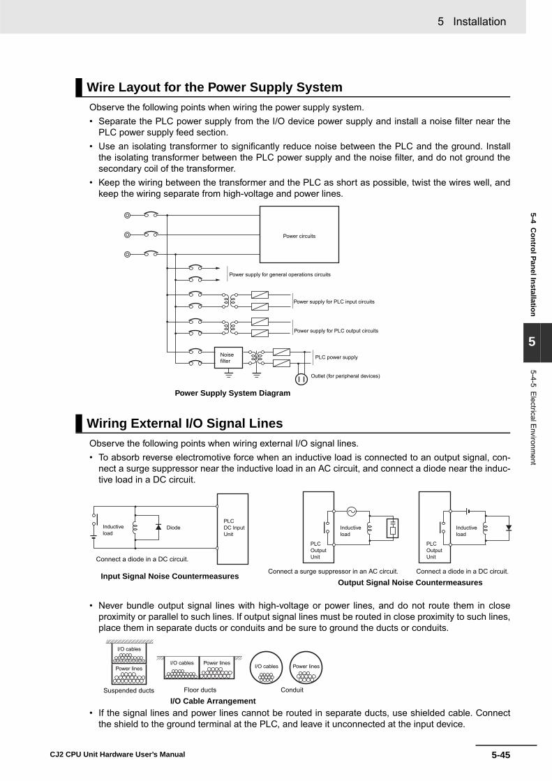
5-45
5 Installation
CJ2 CPU Unit Hardware User’s Manual
5-4 Control Panel Installation
5
5-4-5 Electrical E
nvironment
Observe the following points when wiring the power supply system.• Separate the PLC power supply from the I/O device power supply and install a noise filter near the
PLC power supply feed section.• Use an isolating transformer to significantly reduce noise between the PLC and the ground. Install
the isolating transformer between the PLC power supply and the noise filter, and do not ground thesecondary coil of the transformer.
• Keep the wiring between the transformer and the PLC as short as possible, twist the wires well, andkeep the wiring separate from high-voltage and power lines.
Observe the following points when wiring external I/O signal lines.• To absorb reverse electromotive force when an inductive load is connected to an output signal, con-
nect a surge suppressor near the inductive load in an AC circuit, and connect a diode near the induc-tive load in a DC circuit.
• Never bundle output signal lines with high-voltage or power lines, and do not route them in closeproximity or parallel to such lines. If output signal lines must be routed in close proximity to such lines,place them in separate ducts or conduits and be sure to ground the ducts or conduits.
• If the signal lines and power lines cannot be routed in separate ducts, use shielded cable. Connectthe shield to the ground terminal at the PLC, and leave it unconnected at the input device.
Wire Layout for the Power Supply System
Wiring External I/O Signal Lines
Power Supply System Diagram
Power circuits
Noisefilter
Power supply for general operations circuits
Power supply for PLC input circuits
Power supply for PLC output circuits
PLC power supply
Outlet (for peripheral devices)
Input Signal Noise Countermeasures
PLCDC Input Unit
Inductive load
Diode
Connect a diode in a DC circuit.
Output Signal Noise Countermeasures
PLCOutputUnit
PLCOutputUnit
Connect a diode in a DC circuit.Connect a surge suppressor in an AC circuit.
Inductive load
Inductive load
I/O Cable ArrangementFloor ducts ConduitSuspended ducts
I/O cables
I/O cablesPower lines
Power lines I/O cables Power lines

5 Installation
5-46 CJ2 CPU Unit Hardware User’s Manual
• Wire the lines so that common impedance does not occur. Such wiring will increase the number ofwires, so use common return circuits. Use thick wires with sufficient allowance for the return circuits,and bundle them with lines of the same signal level.
• For long I/O lines, wire the input and output signal lines separately.• Use twisted-pair wires for pilot lamps (and particularly lamps with filaments). • Use countermeasures, such as CR surge absorbers and diodes, for input device and output load
device noise sources, as required.
Wiring, and noise countermeasures in particular, are based on experience, and it is necessary toclosely manage wiring based on experience and information in the manuals.
� Wiring RoutesEach of the following combinations include different signal types, properties, or levels. They willcause the signal-to-noise ratio to drop due to factors such as electrical induction. As a general rulewhen wiring, either use separate cables or separate wiring routes for these items. Future mainte-nance operations and changes to the system will also be made easier by carefully organizing thewiring from the start.• Power lines and signal lines• Input signals and output signals• Analog signals and digital signals• High-level signals and low-level signals• Communications lines and power lines• DC signals and AC signals• High-frequency devices (such as Inverters) and signal lines (communications)
External Wiring

5-47
5 Installation
CJ2 CPU Unit Hardware User’s Manual
5-4 Control Panel Installation
5
5-4-5 Electrical E
nvironment
� Wiring MethodsObserve the following points when wiring power supply and signal cables.• When routing signal cables with differing characteristics through the same duct, always keep them
separated.• As much as possible, avoid routing multiple power supply lines through the same duct. If it cannot
be avoided, then construct a partition between them in the duct and ground the partition.
• To avoid overheating the conduits when using conduits for wiring, do not place wires for a singlecircuit in separate conduits.
Partitioning Methods for Signal and Power Supply Cables
(a) (b)
(c) (d)
Signal cables
Signal cables
Signal cables
Power supply cablesPower supply cables
Partition
Signal cables
(A)
Signalcables (B)
Signalcables
(C)Power supplycables
Parallel Wiring (Single Phase)
Correct
CorrectPower supply
Incorrect
Power supply
Power supply
Load
Load
Load

5 Installation
5-48 CJ2 CPU Unit Hardware User’s Manual
• Power cables and signal cables adversely affect each other. Do not wire them in parallel.• Noise induction may occur if the PLC is installed in a panel that includes high-voltage devices.
Whenever possible, wire and install them separately. (Refer to PLC Installation Location on page44.)
• Either install the PLC a minimum of 200 mm from high-voltage lines or power lines, or place thehigh-voltage lines or power lines in metal tubing and completely ground the metal tubing to 100 Ωor less.
� Other Precautions• Basic I/O Units have both plus and minus commons, so pay attention to the polarity when wiring.• Optical fiber cable looks like ordinary communications cable or power cable, but internally it con-
sists of fibers, tension members, other protective materials. It must be handled with care. In partic-ular, optical fiber cable must be installed according to prescribed methods and standards. Do notsubject optical fiber cable to severe tensile shock, excessive bending, twisting, or excessive con-striction. For details on wiring optical fiber cables, refer to the following manuals.
• SYSMAC H-PCF Optical Fiber Cables Installation Guide (Cat. No. W156)• Optical Ring Controller Link Units Operation Manual (Cat. No. W370)
Example: Separating PLC from Power Lines
PLC
Metal tubing
PLC
200 mm
200 mm
Panel with power linePower line
Ground of 100 Ω or less
Power line

5-49
5 Installation
CJ2 CPU Unit Hardware User’s Manual
5-4 Control Panel Installation
5
5-4-6 Grounding
Grounding has the following two purposes.• Protective Grounding
Protective grounding is done to ensure safety. It is intended to prevent electrical shock by groundingthe electrical potential that is generated by factors such as leakage, induction, or failure.
• Functional GroundingFunctional grounding is done to protect device and system functions, including prevention of noisefrom external sources, or prevention of noise from devices or equipment that could have harmfuleffects on other devices or equipment.
Grounding requirements sometimes depend on the situation, based on experimentation. It is impor-tant to sufficiently check the particular circumstances before grounding.
� Principles of One-point GroundingFor devices to operate properly, the reference potential between the devices must be stabilized. Useone-point grounding so that noise current does not flow to ground lines between the devices.
� Whenever possible, use an independent ground (with the ground pole separated by a minimum of 10 m from any other ground pole).• Ground to 100 Ω or less, and if possible use a separate ground from those of other devices. (Refer
to figure (a) in the diagram below.)• If using an independent ground is not possible, then use a common ground as shown in figure (b).
Connect to the ground pole of the other device. • Never connect to the same ground as a device that draws a large amount of power, such as a
motor or inverter. Ground the devices separately to avoid mutually adverse influences.• To prevent electrical shock, do not connect to ground poles (especially steel frames) to which mul-
tiple devices are connected.• Use a ground pole as close to the PLC as possible and keep the ground line as short as possible.
5-4-6 Grounding
Grounding Methods and Precautions
PLC
Otherdevice
Ground of 100 Ω or less
PLCPLC
Independent grounds: Best
Common ground: Acceptable
Common ground: Incorrect
Grounding Methods
Otherdevice
Otherdevice
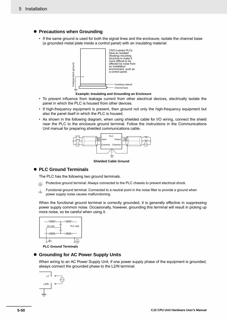
5 Installation
5-50 CJ2 CPU Unit Hardware User’s Manual
� Precautions when Grounding• If the same ground is used for both the signal lines and the enclosure, isolate the channel base
(a grounded metal plate inside a control panel) with an insulating material
• To prevent influence from leakage current from other electrical devices, electrically isolate thepanel in which the PLC is housed from other devices.
• If high-frequency equipment is present, then ground not only the high-frequency equipment butalso the panel itself in which the PLC is housed.
• As shown in the following diagram, when using shielded cable for I/O wiring, connect the shieldnear the PLC to the enclosure ground terminal. Follow the instructions in the CommunicationsUnit manual for preparing shielded communications cable.
� PLC Ground TerminalsThe PLC has the following two ground terminals.
When the functional ground terminal is correctly grounded, it is generally effective in suppressingpower supply common noise. Occasionally, however, grounding this terminal will result in picking upmore noise, so be careful when using it.
� Grounding for AC Power Supply Units When wiring to an AC Power Supply Unit, if one power supply phase of the equipment is grounded,always connect the grounded phase to the L2/N terminal.
Protective ground terminal: Always connected to the PLC chassis to prevent electrical shock.
Functional ground terminal: Connected to a neutral point in the noise filter to provide a ground when power supply noise causes malfunctioning.
Example: Insulating and Grounding an Enclosure
Insulating materialChannel base
Inde
pend
ent g
roun
d
CS/CJ-series PLCs have an isolated (floating) mounting structure to make it more difficult to be affected by noise from an installation environment, such as a control panel.
Shielded Cable Ground
PLCOutput
Common
Input
Common
PLC Ground Terminals
AC side PLC side
L1
L2/N

6-1CJ2 CPU Unit Hardware User’s Manual
6
This section describes how to troubleshoot problems that may occur with a CJ2 PLC.
6-1 CPU Unit Errors . . . . . . . . . . . . . . . . . . . . . . . . . . . . . . . . . . . . . . . . . . . . . . . 6-26-1-1 Errors and Remedies . . . . . . . . . . . . . . . . . . . . . . . . . . . . . . . . . . . . . . . . . . . . 6-26-1-2 Checking Errors . . . . . . . . . . . . . . . . . . . . . . . . . . . . . . . . . . . . . . . . . . . . . . . . 6-26-1-3 Checking Detailed Status . . . . . . . . . . . . . . . . . . . . . . . . . . . . . . . . . . . . . . . . 6-36-1-4 Reading Error Log Information . . . . . . . . . . . . . . . . . . . . . . . . . . . . . . . . . . . . 6-36-1-5 I/O Table Verification . . . . . . . . . . . . . . . . . . . . . . . . . . . . . . . . . . . . . . . . . . . . 6-56-1-6 Types of Errors . . . . . . . . . . . . . . . . . . . . . . . . . . . . . . . . . . . . . . . . . . . . . . . . . 6-66-1-7 Handling Errors . . . . . . . . . . . . . . . . . . . . . . . . . . . . . . . . . . . . . . . . . . . . . . . . 6-7
6-2 Troubleshooting Built-in EtherNet/IP Port Errors (CJ2H-CPU6@-EIP and CJ2M-CPU3@ Only) . . . . . . . . . . . . . . . . . . . . . . . 6-256-2-1 Checking Built-in EtherNet/IP Port Error Status . . . . . . . . . . . . . . . . . . . . . . 6-256-2-2 Checking Error Status at the EtherNet/IP Port Seven-segment Display . . . . 6-26
6-3 Non-CPU Unit Errors and Remedies . . . . . . . . . . . . . . . . . . . . . . . . . . . . . 6-286-3-1 Error Causes and Remedies . . . . . . . . . . . . . . . . . . . . . . . . . . . . . . . . . . . . . 6-28
Troubleshooting

6 Troubleshooting
6-2 CJ2 CPU Unit Hardware User’s Manual
6-1 CPU Unit Errors
Use the following procedure when an error occurs.
The type of error that occurred can be determined by checking the indicators on the front of the CPUUnit or by using the CX-Programmer. For details on error types, refer to 6-1-6 Types of Errors.
6-1-1 Errors and Remedies
6-1-2 Checking Errors
Checking the Indicators
RUN: Lit green when the PLC is in RUN or MONITOR mode.
ERR/ALM: Shows the results of self-diagnosis.Flashing red: Non-fatal error Lit red: Fatal error
INH: Lit yellow when Output OFF Bit has been turned ON.
PRPHL: Flashing yellow when the CPU Unit is communicating through the peripheral (USB) port.
COMM*: Flashing yellow when the CPU Unit is communicating through the RS-232C (USB) port.
BKUP: Flashing yellow when data is being backed up from RAM to built-in flash memory.
* The CJ2M-CPU3@ does not have this indicator.
POWER: Lit when 5 V is output from the Power Supply Unit.
Error occurs.
Check the indicators.
Identify the error.
Implementcountermeasures.
End
Check the indicators on the front of the CPU Unit and Power Supply Unit, or use the CX-Programmer to read the error status.
Identify the error from the indicators (refer to 6-1-6 Types of Errors) or use the CX-Programmer to read the error status.
Take measures to eliminate the error that occurred and to prevent it from occurring again. (Refer to 6-1-7 Handling Errors.)
RUNERR/ALMINHPRPHL/COMMBKUP
Indicators on front of CPU Unit
Power Supply UnitPower indicator
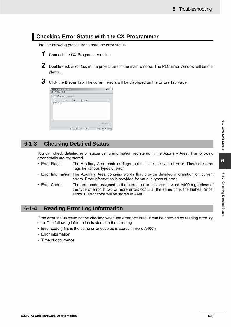
6-3
6 Troubleshooting
CJ2 CPU Unit Hardware User’s Manual
6-1 CPU
Unit Errors
6
6-1-3 Checking D
etailed Status
Use the following procedure to read the error status.
1 Connect the CX-Programmer online.
2 Double-click Error Log in the project tree in the main window. The PLC Error Window will be dis-played.
3 Click the Errors Tab. The current errors will be displayed on the Errors Tab Page.
You can check detailed error status using information registered in the Auxiliary Area. The followingerror details are registered.• Error Flags: The Auxiliary Area contains flags that indicate the type of error. There are error
flags for various types of error.• Error Information: The Auxiliary Area contains words that provide detailed information on current
errors. Error information is provided for various types of error.• Error Code: The error code assigned to the current error is stored in word A400 regardless of
the type of error. If two or more errors occur at the same time, the highest (mostserious) error code will be stored in A400.
If the error status could not be checked when the error occurred, it can be checked by reading error logdata. The following information is stored in the error log.• Error code (This is the same error code as is stored in word A400.)• Error information• Time of occurrence
Checking Error Status with the CX-Programmer
6-1-3 Checking Detailed Status
6-1-4 Reading Error Log Information

6 Troubleshooting
6-4 CJ2 CPU Unit Hardware User’s Manual
A maximum of 20 error records will be stored in the error log. If more than 20 errors occur, the oldesterror record (in A100 to A104) will be deleted and the 19 records stored in A105 to A199 will be shiftedby one, with the newest record being stored in A195 to A199.
The following methods can be used to check error log information with the CX-Programmer.
� CX-Programmer PLC Error WindowCheck the error log by clicking the Error Log Tab in the PLC Errors Window of the PLC.
The example above shows that unit number 17 has been duplicated for Special I/O Units.• Error code 80E9: Unit number duplication error• Error information: 80 “11”: 11 hex = 17 decimal
For details on error codes and error information, refer to A-3 Fatal and Non-fatal Error Details.
� Directly Monitoring the Area where Error Log Information is Stored
1 Connect the CX-Programmer online.
2 Read words A100 to A199.
Error Log Information
Checking Error Log Information
A100 4 1 0 2 A101 A102 A103 A104 A105 0 0 F 7 A106 A107 A108 A109 A195 0 0 9 D A196 A197 A198 A199
4102
00F7
009D
1
2
20
A300
Error log pointer
Error code
Error code
Error code Order of occurrence
Error Log Area
Error contents
Minute, secondDay, hour Time of occurrenceYear, month
Error code
Error contents
Error contentsMinute, secondDay, hour
Year, month
Minute, secondDay, hour
Year, month
Time of occurrence
Time of occurrence
The error information is displayed here.
The error code is displayed here.

6-5
6 Troubleshooting
CJ2 CPU Unit Hardware User’s Manual
6-1 CPU
Unit Errors
6
6-1-5 I/O Table Verification
3 Check the error status from the registered data.
When an I/O verification error or a CPU standby error occurs, the following procedure can be used toverify the I/O tables to locate where the error occurred. With the CX-Programmer, use the following pro-cedure.
1 Double-click I/O Tables in the project tree in the main window.
The I/O Table Window will be displayed.
2 Select Verify from the Options Menu in the I/O Table Window.
The I/O table verification results will be displayed.
6-1-5 I/O Table Verification

6 Troubleshooting
6-6 CJ2 CPU Unit Hardware User’s Manual
The type of error that has occurred can be identified by checking the indicators on the front of the CPUUnit and the Power Supply Unit, or by using the CX-Programmer to check the error status. The errorsdetected by the CPU Unit are listed in the following table. For details on errors that are not detected by the CPU Unit, refer to 6-3 Non-CPU Unit Errors and Rem-edies.
*1 The indicator status is the same for CPU errors and fatal errors, but they can be distinguished because a ProgrammingDevice can be connected when a fatal error occurs, but not when a CPU error occurs.
*2 For details on fatal errors and non-fatal errors, refer to A-3 Fatal and Non-fatal Error Details.*3 CJ2H-CPU6@-EIP only.Note The indicator status shows the status of the errors that have occurred in RUN or MONITOR mode.
6-1-6 Types of Errors
Error name POWER RUN ERR/ALM INH PRPHL COMMError code (stored in
A400)Operation status
Power supply error OFF OFF OFF OFF OFF OFF --- Operation stops.
CPU Standby ON OFF OFF --- --- --- --- Operation stops.
CPU reset --- Operation stops.
CPU error (WDT error)*1 ON OFF ON --- --- --- --- Operation stops.
USB port communications error ON ON OFF --- OFF --- --- Operation continues.
RS-232C port communications error
ON ON OFF --- --- OFF --- Operation continues.
Fata
l erro
rs*1
*2
Cycle time exceeded error ON OFF ON --- --- --- 0x809F Operation stops.
I/O bus error 0x80C0 to 0x80C7, 0x80CE, 0x80CF
I/O setting error 0x80E0
Too many I/O points error 0x80E1
Unit number duplication error
0x80E9
Rack number duplication error
0x80EA
Program error 0x80F0
Memory error 0x80F1
Version error 0x80F2
Memory Card Transfer Error
0x80F4
FALS (007) error 0xC101 to 0xC2FF
Non
-fata
l err
ors*
2
Duplicated refreshing error ON ON Flashing --- --- --- 0x008B Operation continues.
Basic I/O error 0x009A
PLC Setup error 0x009B
Option Board error 0x00D1
Backup memory error 0x00F1
Tag memory error*3 0x00F2
System work errors 0x00F3
Battery error 0x00F7
CPU Bus Unit error 0x0200 to 0x020F
Special I/O Unit error 0x0300 to 0x035F, 0x03FF
CPU Bus Unit setting error 0x0400 to 0x040F
FAL (006) error 0x4101 to 0x42FF
Special I/O Unit setting error
0x0500 to 0x055F

6-7
6 Troubleshooting
CJ2 CPU Unit Hardware User’s Manual
6-1 CPU
Unit Errors
6
6-1-7 Handling E
rrors
This section describes the measures to take for the errors that most commonly occur. First check theerror status. Then, make a preliminary determination of the cause of the error, confirm the cause, cor-rect the error, and take measures to ensure that it will not occur again. For all other errors, refer to A-3Fatal and Non-fatal Error Details.
A power supply error occurs when a voltage of 5 V is not output from the Power Supply Unit.
*1 The following table shows the allowable power supply ranges for each Power Supply Unit model.
6-1-7 Handling Errors
Power Supply Errors
POWER RUN ERR/ALM Error flag Error code Error infor-mation
Not lit. Not lit. Not lit. None None None
Suspected cause of error Confirmation method Remedy Prevention of recur-
rencePower is not being input.
Use a tester to measure the volt-age at the input terminals of the Power Supply Unit.*1
Turn the power ON again.
Investigate the reason that the power was turned OFF.
Connection status of power supply selector terminals
• 100 VAC: Use a tester check for short-circuits.
• 200 VAC: Check for disconnections.
Reconnect and secure the terminal connec-tions.
Periodically (approxi-mately once a year) tighten the terminal con-nections.
The voltage is out of the allowable range for the power supply.
Use a tester to measure the volt-age at the input terminals to the Power Supply Unit.*1
Correct the power sup-ply system for the PLC.
Same as at the left.
Power Supply Unit fail-ure
Replace the Power Supply Unit and check operation. (Check whether the POWER indicator is lit.)
Replace the Power Supply Unit.
Depends on the type of error.
Failure at another Unit Remove in order the Units mounted in the Rack and check the POWER indicator.
Replace the failed Unit. Depends on the type of error.
Model Power supply voltage Allowable power supply voltage fluctuation
CJ1W-PA205R/PA202 100 to 240 VAC 85 to 264 VAC
CJ1W-PD025 24 VDC 19.2 to 28.8 VDC

6 Troubleshooting
6-8 CJ2 CPU Unit Hardware User’s Manual
When a CJ-series PLC is turned ON, the CPU starts cyclic servicing and enters RUN mode only afterall Special I/O Units and CPU Bus Units have been detected. If the startup mode is RUN or MONITORmode, the CPU will remain on standby until all Units have been detected.
� Recovery Processing Flow
� Error Causes and Remedies
CPU Standby Errors
POWER RUN ERR/ALM Error flag Error code Error infor-mation
Lit. Not lit. Not lit. None None None
Suspected cause of error Confirmation method Remedy Prevention of
recurrenceFaulty connection at Unit (at a connector)
Check the insertion at the connector. Restart the Unit and check whether the error is cleared.
Tighten the screws. Same as at the left.
Unit failure Replace the Unit that is causing the standby (the undetected Unit). If the error is not cleared, remove the Units in order until the status returns to normal.
• Replace the Special I/O Unit or Interrupt Unit for which “$” is displayed when the I/O tables are read.
• Replace the failed Unit.
(Determined by the cause of the failure.)
The remote I/O power supply is OFF or there is no terminator for SYSMAC BUS.
Check whether the power is turned ON. Check the termi-nator settings.
Turn ON the power or set the terminators. If the error is not cleared, replace the Unit.
---
CPU standby
Check the location of the error.
Check the connection status.
Replace the Unit.
Is the error cleared?
YesNo
Restart the System.
Use the I/O table verification procedure (refer to 6-1-5 I/O Table Verification) to check the location where the error occurred.
Check the connections to the Special I/O Units and CPU Bus Units.
Replace the Unit, or remove the Unit and check whether the error is cleared (to determine that the Unit that was replaced or removed just before the error was cleared was the problem).

6-9
6 Troubleshooting
CJ2 CPU Unit Hardware User’s Manual
6-1 CPU
Unit Errors
6
6-1-7 Handling E
rrors
Additional Information
The CJ2 CPU Units support the following function.
• Startup Condition Setting
After the power supply is turned ON, it is possible to start operation of the CPU Unit in RUNmode or MONITOR mode even if there is one or more Units that has not completed startup.Select the Start running program when initializing Unit/Inner board recognition Check Box inthe PLC Setup. For details, refer to the CJ-series CJ2 CPU Unit Software User's Manual(Cat. No. W473).
The CPU Unit is being reset, and Programming Devices cannot be connected.
� Error Causes and Remedies
*1 The following table shows the allowable power supply ranges for each Power Supply Unit.
Precautions for Correct UsePrecautions for Correct Use
Observe the following points when using Expansion Racks.• Always confirm the safety of any related equipment before turning the power supply ON or
OFF. • When the power supply is interrupted to an Expansion Rack, the CPU Unit will stop program
execution and the same operations as are performed when the power supply to the CPU Unitis interrupted will be performed. For example, if the power OFF interrupt task is enabled, it willbe executed. If power is then restored to the Expansion Rack, the CPU Unit will perform star-tup processing. The same operational status as existed before the power interrupt will not nec-essarily be continued.
CPU Reset
POWER RUN ERR/ALM Error flag Error code Error infor-mation
Lit. Not lit. Not lit. None None None
Suspected cause of error Confirmation method Remedy Prevention of recurrence
Power to an Expansion Rack is OFF. Use a tester to measure the voltage at the input terminals of the Power Supply Unit.*1
Turn ON the power.
Investigate the reason that the power was OFF.
The I/O Connecting Cable is incorrectly installed.• The IN-OUT connectors are reversed.• The cable does not have good contact at the
connectors.• Two or more I/O Control Units are mounted on
the CPU Rack, or an I/O Control Unit is mounted to an Expansion Rack.
Check the connections. Reconnect the cable.
If the Cable is dis-connected, check for vibration and shock.
Model Power supply voltage Allowable power supply voltage fluctuation
CJ1W-PA205R/PA202 100 to 240 VAC 85 to 264 VAC
CJ1W-PD025 24 VDC 19.2 to 28.8 VDC

6 Troubleshooting
6-10 CJ2 CPU Unit Hardware User’s Manual
CPU errors are error that occur in the CPU Unit itself. A CPU error occurs when the WDT (watchdogtimer) times out. Programming Devices cannot be connected when a CPU error occurs.
� Error Causes and Remedies
Precautions for Correct UsePrecautions for Correct Use
• Always confirm the safety of any related equipment before turning the power supply ON orOFF.
• When power supply is interrupted to an Expansion Rack, the CPU Unit will stop program exe-cution and the same operations as are performed when the power supply to the CPU Unit isinterrupted will be performed. For example, if the power OFF interrupt task is enabled, it will beexecuted. If power is then restored to the Expansion Rack, the CPU Unit will perform startupprocessing. The same operational status as existed before the power interrupt will not neces-sarily be continued.
CPU Errors
POWER RUN ERR/ALM Error flag Error code Error informationLit. Not lit. Lit. None None None
Suspected cause of error Confirmation method Remedy Prevention of recur-
renceUnit failure A CPU error has possibly occurred
in the following cases.• If the error is not cleared when the
CPU Unit is restarted after the recovery measures.
• If the error occurs frequently• If the condition improves when the
Unit is replaced.
Replace the CPU Unit. Same as at the left.
A conductive object has gotten inside.
Check for conductive objects. Clean the inside of the Unit with an air blower or replace the CPU Unit.
Do not do any metal working in the vicinity of the control panel. Close the control panel.
Noise• The microcomputer
inside the CPU Unit is malfunctioning.
When the CPU Unit is restarted after the recovery measures, the error will either be cleared or will continue to occur. Check whether errors become less frequent after the Unit is replaced.
Take measures against noise. (Investigate the path of entry.)• FG• Power lines
Same as at the left.

6-11
6 Troubleshooting
CJ2 CPU Unit Hardware User’s Manual
6-1 CPU
Unit Errors
6
6-1-7 Handling E
rrors
A communications error will occur if there is an error in communications between the peripheral (USB)Port and a connected device.
� Error Causes and Remedies
A communications error will occur if there is an error in communications between the serial (RS-232C)port and a connected device.
� Error Causes and Remedies
Communications Error (Peripheral (USB) Port)
POWER RUN ERR/ALM PRPHL COMM Error flag Error code Error informationLit. Lit. Not lit. Not lit. Not lit. None None None
Suspected cause of error Confirmation method Remedy Prevention of recur-
renceThe communications cable is disconnected.
Perform a visual inspec-tion and pull on the cables.
Reconnect the cables. During operation, confirm that the connections are secure. Check for vibration or shock.
Communications Error (Serial Port (RS-232C))
POWER RUN ERR/ALM PRPHL COMM Error flag Error code Error informationLit. Lit. Not lit. Not lit. Not lit. None None None
Suspected cause of error Confirmation method Remedy Prevention of recur-
renceCommunications set-tings are incorrect.
• Check whether the DIP switch pin 5 setting and and the serial port settings in the PLC Setup are cor-rect.
• If a host computer is con-nected, check the host computer serial port set-tings and the program.
• Correctly set DIP switch pin 5 and the serial port settings in the PLC Setup.
• Correct the host computer serial port settings and the program.
Same as at the left.
A communications cable is incorrectly connected.
• Check the cable connec-tions.
• Correct the cable connec-tions.
Same as at the left.
A communications cable is disconnected.
Perform a visual inspection and pull on the cables.
Reconnect the cables. During operation, confirm that the connections are secure. Check for effects of vibration or shock.
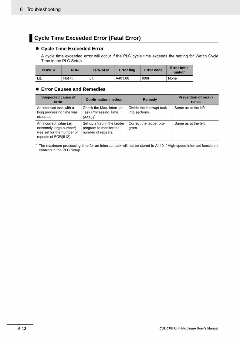
6 Troubleshooting
6-12 CJ2 CPU Unit Hardware User’s Manual
� Cycle Time Exceeded ErrorA cycle time exceeded error will occur if the PLC cycle time exceeds the setting for Watch CycleTime in the PLC Setup.
� Error Causes and Remedies
* The maximum processing time for an interrupt task will not be stored in A440 if High-speed interrupt function isenabled in the PLC Setup.
Cycle Time Exceeded Error (Fatal Error)
POWER RUN ERR/ALM Error flag Error code Error infor-mation
Lit. Not lit. Lit. A401.08 809F None
Suspected cause of error Confirmation method Remedy Prevention of recur-
renceAn interrupt task with a long processing time was executed.
Check the Max. Interrupt Task Processing Time (A440)*
Divide the interrupt task into sections.
Same as at the left.
An incorrect value (an extremely large number) was set for the number of repeats of FOR(512).
Set up a trap in the ladder program to monitor the number of repeats.
Correct the ladder pro-gram.
Same as at the left.
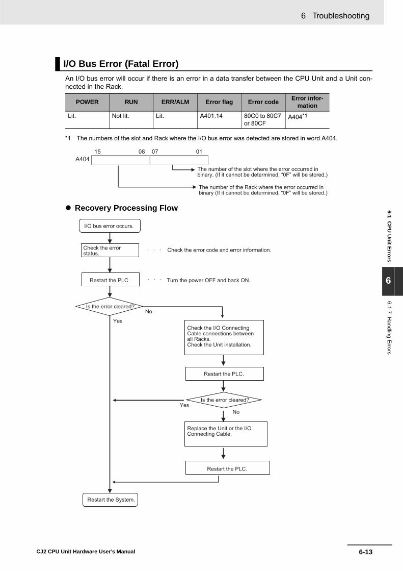
6-13
6 Troubleshooting
CJ2 CPU Unit Hardware User’s Manual
6-1 CPU
Unit Errors
6
6-1-7 Handling E
rrors
An I/O bus error will occur if there is an error in a data transfer between the CPU Unit and a Unit con-nected in the Rack.
*1 The numbers of the slot and Rack where the I/O bus error was detected are stored in word A404.
� Recovery Processing Flow
I/O Bus Error (Fatal Error)
POWER RUN ERR/ALM Error flag Error code Error infor-mation
Lit. Not lit. Lit. A401.14 80C0 to 80C7 or 80CF
A404*1
15 08 07 01A404
The number of the slot where the error occurred in binary. (If it cannot be determined, “0F” will be stored.)
The number of the Rack where the error occurred in binary (If it cannot be determined, “0F” will be stored.)
I/O bus error occurs.
Check the error status. Check the error code and error information.
Restart the PLC Turn the power OFF and back ON.
Is the error cleared?No
Yes
YesNo
Is the error cleared?
Check the I/O Connecting Cable connections between all Racks.Check the Unit installation.
Restart the PLC.
Replace the Unit or the I/O Connecting Cable.
Restart the PLC.
Restart the System.

6 Troubleshooting
6-14 CJ2 CPU Unit Hardware User’s Manual
� Error Causes and RemediesSuspected cause of
error Confirmation method Remedy Prevention of recur-rence
The I/O Connecting Cable is disconnected.
Perform a visual inspec-tion and pull on the Cables.
Reconnect the cables. During operation, confirm that the connections are secure. Check for vibration or shock.
Equipment failure• CPU Unit• I/O Connecting Cable
(damage to bus inter-face circuit)
An I/O bus error has pos-sibly occurred in the fol-lowing cases. • If the error is not cleared
when the CPU Unit is restarted
• If the error occurs fre-quently
• If the condition improves when the Unit is replaced.
Replace the equipment.• CPU Unit• I/O Connecting Cable
---
A conductive object has gotten inside.
Check for conductive objects.
Clean the inside of the Unit with an air blower or replace the CPU Unit.
Do not do any metal work-ing in the vicinity of the control panel. Close the control panel.
Faulty connector contact (A foreign object has got-ten inside.)
Check for foreign objects in the connector.
Replace the Unit or take off the connector and remove the foreign object.
Make sure that the operat-ing environment is free of dirt and dust.
Noise• Data corruption in bus
signals• Malfunctioning in bus
interface circuit
When the CPU Unit is restarted after the recov-ery measures, the error will either be cleared or will continue to occur. Check whether errors become less frequent after the Unit is replaced.
Take measures against noise. (Investigate the path of entry.)• FG• Power lines• I/O connecting cable
(inductive noise)
Same as at the left.
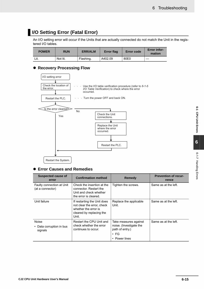
6-15
6 Troubleshooting
CJ2 CPU Unit Hardware User’s Manual
6-1 CPU
Unit Errors
6
6-1-7 Handling E
rrors
An I/O setting error will occur if the Units that are actually connected do not match the Unit in the regis-tered I/O tables.
� Recovery Processing Flow
� Error Causes and Remedies
I/O Setting Error (Fatal Error)
POWER RUN ERR/ALM Error flag Error code Error infor-mation
Lit. Not lit. Flashing. A402.09 80E0 ---
Suspected cause of error Confirmation method Remedy Prevention of recur-
renceFaulty connection at Unit (at a connector)
Check the insertion at the connector. Restart the Unit and check whether the error is cleared.
Tighten the screws. Same as at the left.
Unit failure If restarting the Unit does not clear the error, check whether the error is cleared by replacing the Unit.
Replace the applicable Unit.
Same as at the left.
Noise• Data corruption in bus
signals
Restart the CPU Unit and check whether the error continues to occur.
Take measures against noise. (Investigate the path of entry.)• FG• Power lines
Same as at the left.
I/O setting error
Use the I/O table verification procedure (refer to 6-1-5I/O Table Verification) to check where the error occurred.
Restart the PLC. Turn the power OFF and back ON.
Is the error cleared?No
Yes
Restart the System.
Check the location of the error.
Check the Unit connections.
Replace the Unit where the error occurred.
Restart the PLC.

6 Troubleshooting
6-16 CJ2 CPU Unit Hardware User’s Manual
A memory error will occur if there is a memory error in the CPU Unit or if a checksum error is detected(checksum checked by the PLC with each cycle). The details of the cause of the error will be stored inthe error information in the Auxiliary Area.
*1 Individual bits in A403 indicate where the memory error occurred.
� Recovery MeasuresCheck the detailed error contents in the error information in the Auxiliary Area, and then implementthe following recovery measures. If these measures cannot solve the problem, there is a strongprobability that the Unit has failed, so replace the Unit.
Additional Information
Checksums are used to detect illegal rewriting in a specific area of memory by calculating andcomparing sums written to memory in advance to sums during operation. When a checksumerror is detected by the CJ2 CPU Unit during operation, memory is automatically recovered byautomatically reading data from flash memory. If recovery is not possible, an error occurs andoperation stops.
Use any of the following methods to transfer the data again.• Use the CX-Programmer to download data.• Use the automatic transfer at startup function to download data saved on a Memory Card. For
details, refer to the CJ-series CJ2 CPU Unit Software User's Manual (Cat. No. W473). • Use the simple backup function to download data saved on a Memory Card. For details, refer
to 8-3 Simple Backup.
The CJ2 CPU Unit has built-in flash memory for backup. When the CPU Unit is restarted, data istransferred to memory for calculation and this sometimes enables an error to be cleared.
Memory Error (Fatal Error)
POWER RUN ERR/ALM Error flag Error code Error infor-mation
Lit. Not lit. Lit. A401.15 80F1 A403*1
Error information Error contents Recovery measuresA403.00: ON A checksum error has occurred in the user
program memory. Transfer the user program to the CPU Unit again.
A403.04: ON A checksum error has occurred in the PLC Setup.
Transfer the PLC Setup to the CPU Unit again.
A403.05: ON A checksum error has occurred in the reg-istered I/O table.
Transfer the I/O tables to the CPU Unit again.
A403.07: ON A checksum error has occurred in the routing tables.
Transfer the routing tables to the CPU Unit again.
A403.08: ON A checksum error has occurred in the CPU Bus Unit setup.
Transfer the CPU Bus Unit setup again.
A403.09: ON An error occurred during automatic trans-fer from the Memory Card at startup.
The following files are required for auto-matic transfer at startup. Save these files to the Memory Card and restart.• Program file: AUTOEXEC.OBJ• Parameters file: AUTOEXEC.STD

6-17
6 Troubleshooting
CJ2 CPU Unit Hardware User’s Manual
6-1 CPU
Unit Errors
6
6-1-7 Handling E
rrors
� Recovery Processing Flow
� Error Causes and RemediesIf the measures described above do not clear the error, take the measures shown in the followingtable.
*1 This refers to errors caused by data corruption. SRAM is used for the CPU Unit user memory. SRAM isaffected by cosmic rays (neutrons) and naturally occurring radiation, so data can become corrupted.
Suspected cause of error Confirmation method Remedy Prevention of recur-
renceUnit failure• Memory element failure• Memory peripheral cir-
cuit failure
A memory error has prob-ably occurred in the follow-ing cases.• If the error is not cleared
when the CPU Unit is restarted after the recovery measures
• If the error occurs fre-quently
• If the condition improves when the Unit is replaced.
Replace the CPU Unit. Determined by the cause of the failure.
A conductive object has gotten inside.
Check for conductive objects.
Clean the inside of the Unit with an air blower or replace the CPU Unit.
Do not do any metal work-ing in the vicinity of the control panel. Close the control panel.
Noise• Data corruption in mem-
ory• Microcomputer malfunc-
tioning • Memory write circuit
malfunctioning
When the CPU Unit is restarted after the recov-ery measures, the error will either be cleared or will continue to occur. Check whether errors become less frequent after the Unit is replaced.
Take measures against noise. (Investigate the path of entry.)• FG• Power lines
Same as at the left.
Software error*1 None None None
Memory error
Check the error status.
Implement the remedy.
Is the error cleared?
YesNo
Replace the Unit.
Restart the System.

6 Troubleshooting
6-18 CJ2 CPU Unit Hardware User’s Manual
A basic I/O error occurs when there is an error at a Basic I/O Unit.
*1 Error Information
� Recovery Processing Flow
� Error Causes and Remedies
Basic I/O Error (Non-fatal Error)
POWER RUN ERR/ALM Error flag Error code Error infor-mation
Lit. Not lit. Flashing. A402.12 009A A408*1
Suspected cause of error Confirmation method Remedy Prevention of recur-
renceA fuse is burned out. Measure the voltage at the
power supply terminals. Check whether 24 V is being supplied. (Check whether the problem is solved by replacing the fuse.)
Replace the fuse. Check the maximum switching current.
The external power supply is OFF (disconnected).
Measure the voltage at the power supply terminals. Check whether 24 V is being supplied.
Turn ON the power supply. Investigate the reason that the power was turned OFF.
Other errors specific to Units
Refer to the manual for the particular Unit.
Same as at the left. Same as at the left.
15 08 07 01A408
Number of slot where the Unit with the error is mounted in binary.
Number of Rack where the Unit with the error is mounted in binary.
Basic I/O error occurs.
Check the location of the error. Check the error information (A408).
Replace the Unit. Check the cause of the error, and take measures to prevent it from occurring again.
Restart the System.

6-19
6 Troubleshooting
CJ2 CPU Unit Hardware User’s Manual
6-1 CPU
Unit Errors
6
6-1-7 Handling E
rrors
An Option Board error will occur if the Option Board is removed while the power is being supplied.
� Recovery Processing Flow
� Error Causes and Remedies
Option Board Errors
POWER RUN ERR/ALM Error flag Error code Error infor-mation
Lit. Lit. Flashing. A315.13A402.00
00D1 ---
Suspected cause of error Confirmation method Remedy Prevention of recur-
renceThe Option Board was removed while the system was operating.
Check the mating of the Option Board connector.
Reconnect. Check for vibration and shock.
Option Board failure If restarting does not clear the error, check whether the error is cleared by replacing the Option Board.
Replace the Option Board. Same as at the left.
Check the location of the error.
YesNo
Option Board error occurs.
Restart the System.
Replace the Option Board.
Restart the PLC.
Restart the PLC.
Check the Unit connections.
Recovered?

6 Troubleshooting
6-20 CJ2 CPU Unit Hardware User’s Manual
A battery error occurs when the battery voltage drops.
� Recovery Processing Flow
� Error Causes and Remedies
Battery Error (Non-fatal Error)
POWER RUN ERR/ALM Error flag Error code Error infor-mation
Lit. Not lit. Flashing. A402.04 00F7 ---
Suspected cause of error Confirmation method Remedy Prevention of recur-
renceA connector is discon-nected.
Check the connection at the connector.
Reconnect the connector. Check for vibration and shock.
Battery voltage is low. Check whether the error is cleared by replacing the battery.
Replace the battery.For details, refer to 7-2 Replacing the Battery.
Periodically replace the battery.
Battery error occurs.
Normal?Yes
No
Reconnect
Restart the System.
Replace the battery.
Check the battery connections.

6-21
6 Troubleshooting
CJ2 CPU Unit Hardware User’s Manual
6-1 CPU
Unit Errors
6
6-1-7 Handling E
rrors
A CPU Bus Unit error occurs when there is an error in the data conversion between the CPU Unit and aCPU Bus Unit.
* The bit corresponding to the unit number where the error occurred turns ON. (Bits 00 to 15 correspond to unitnumbers 0 to F.)
� Recovery Processing Flow
� Error Causes and Remedies
CPU Bus Unit Error (Non-fatal Error)
POWER RUN ERR/ALM Error flag Error code Error infor-mation
Lit. Not lit. Flashing. A402.07 0200 to 020F A417*
Suspected cause of error Confirmation method Remedy Prevention of recur-
renceAn error specific to the Unit
Refer to the manual for the particular Unit.
Same as at the left. Same as at the left.
Faulty connection at Unit (at a connector)
Check the insertion at the connector. Restart the Unit and check whether the error is cleared.
Tighten the screws. Check for vibration and shock.
Unit failure If restarting the Unit does not clear the error, check whether the error is cleared by replacing the Unit.
Replace the applicable Unit.
Same as at the left.
Noise• Data corruption in bus
signals
Restart the CPU Unit and check whether the error occurs again.
Take measures against noise. (Investigate the path of entry.)• FG• Power lines
Same as at the left.
CPU Bus Unit error occurs.
Check the location where the error occurred. Use the I/O table verification procedure
(refer to 6-1-5 I/O Table Verification) to check where the error occurred.
Turn the power OFF and back ON.
Yes
No
Check the Unit connections
Restart the PLC.
Restart the System.
Restart the PLC
Is the error cleared?
Replace the Unit where the error occurred.

6 Troubleshooting
6-22 CJ2 CPU Unit Hardware User’s Manual
A Special I/O Unit error occurs when there is an error in the data conversion between the CPU Unit anda Special I/O Unit.
* The bit corresponding to the unit number where the error occurred turns ON.
� Recovery Processing Flow
� Error Causes and Remedies
Special I/O Unit Error (Non-fatal Error)
POWER RUN ERR/ALM Error flag Error code Error informationLit. Not lit. Flashing. A402.06 0300 to 035F
or 03FFA418 to A423 *
Suspected cause of error Confirmation method Remedy Prevention of recur-
renceAn error specific to the Unit
Refer to the manual for the particular Unit.
Same as at the left. Same as at the left.
Faulty connection at Unit (at a connector)
Check the insertion at the connector. Restart the Unit and check whether the error is cleared.
Tighten the screws. Check for vibration and shock.
Unit failure If restarting the Unit does not clear the error, check whether the error is cleared by replacing the Unit.
Replace the applicable Unit.
Same as at the left.
Noise• Data corruption in bus
signals
Restart the CPU Unit and check whether the error occurs again after this.
Take measures against noise. (Investigate the path of entry.)• FG• Power lines
Same as at the left.
Special I/O Unit error occurs.
Restart the Special I/O Unit. Reset, or turn the power OFF and back ON.
Is the error cleared?
YesNo
Check the Unit connections.
Replace the Special I/O Unit.
Restart the Special I/O Unit.
Restart the System.
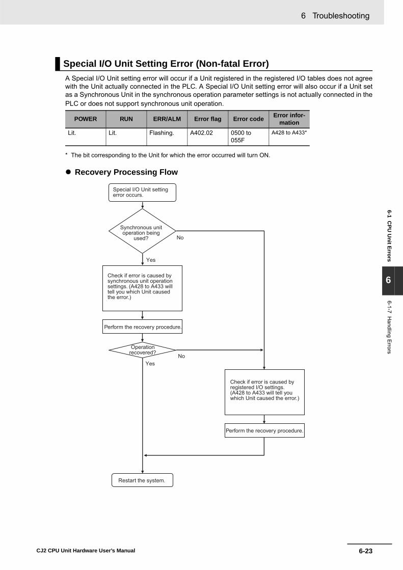
6-23
6 Troubleshooting
CJ2 CPU Unit Hardware User’s Manual
6-1 CPU
Unit Errors
6
6-1-7 Handling E
rrors
A Special I/O Unit setting error will occur if a Unit registered in the registered I/O tables does not agreewith the Unit actually connected in the PLC. A Special I/O Unit setting error will also occur if a Unit setas a Synchronous Unit in the synchronous operation parameter settings is not actually connected in thePLC or does not support synchronous unit operation.
* The bit corresponding to the Unit for which the error occurred will turn ON.
� Recovery Processing Flow
Special I/O Unit Setting Error (Non-fatal Error)
POWER RUN ERR/ALM Error flag Error code Error infor-mation
Lit. Lit. Flashing. A402.02 0500 to 055F
A428 to A433*
Special I/O Unit setting error occurs.
Synchronous unit operation being
used?
Check if error is caused by synchronous unit operation settings. (A428 to A433 will tell you which Unit caused the error.)
Perform the recovery procedure.
Operation recovered?
Restart the system.
Check if error is caused by registered I/O settings. (A428 to A433 will tell you which Unit caused the error.)
Perform the recovery procedure.
NoYes
No
Yes

6 Troubleshooting
6-24 CJ2 CPU Unit Hardware User’s Manual
� Error Causes and Remedies for Synchronous Unit Operation Settings
� Error Causes and Remedies for Registered I/O Table Settings
Suspected cause of error Confirmation method Remedy Prevention of recur-
renceA Unit set in the synchro-nous unit operation set-tings does not support synchronous unit opera-tion.
Check the operation man-ual for the Unit.
Transfer the settings again.
Same as at the left.
A Unit set in the synchro-nous unit operation set-tings does not exist in the PLC.
Check the Units in the PLC.
Transfer the settings again.
Same as at the left.
A Unit set in the synchro-nous unit operation set-tings does not exist on the CPU Rack (i.e., it is on an Expansion Rack).
Check the Units in the PLC.
Move the Synchronous Unit to the CPU Rack. If I/O tables have been registered, change the registered I/O tables.
Same as at the left.
Suspected cause of error Confirmation method Remedy Prevention of recur-
renceThe model of a CPU Bus Unit in the registered I/O tables is different from the model the Unit actually mounted in the PLC.
Check the Units in the PLC.
Correct the I/O table set-tings.
Same as at the left.

6-25
6 Troubleshooting
CJ2 CPU Unit Hardware User’s Manual
6-2 Built-in EtherN
et/IP Port Errors and Rem
edies (CJ2H
-CPU
6@-EIP O
nly)
6
6-2-1 Checking B
uilt-in EtherN
et/IP Port E
rror Status
6-2 Troubleshooting Built-in EtherNet/IP Port Errors (CJ2H-CPU6@-EIP and CJ2M-CPU3@ Only)
Built-in EtherNet/IP port errors can be checked on the built-in EtherNet/IP port seven-segment displayon the front of the CJ2H-CPU6@-EIP or CJ2M-CPU3@ CPU Unit.
Precautions for Correct UsePrecautions for Correct Use
• For details on the types of errors related to the built-in EtherNet/IP port, and measures for han-dling them, refer to the CS/CJ Series EtherNet/IP Units Operation Manual (Cat. No. W465).
6-2-1 Checking Built-in EtherNet/IP Port Error Status
Built-in EtherNet/IP port seven-segment display

6 Troubleshooting
6-26 CJ2 CPU Unit Hardware User’s Manual
� Normal Operation
� Errors Related to CPU Unit Data Exchange
� Errors Related to the CPU Unit
� Errors Related to the Control Bits
6-2-2 Checking Error Status at the EtherNet/IP Port Seven-segment Display
The seven-segment display alternately displays the built-in EtherNet/IP port node address and the following error codes.
IndicationsError
MS NS 7-segment Lit green Lit or flashing
greenBuilt-in Ether-Net/IP port node address
Normal
IndicationsError
MS NS 7-segmentFlashing red Not lit H1 Duplicate unit number
Flashing red Not lit H2 CPU Unit faulty
Lit red Not lit H3 Built-in EtherNet/IP port faulty
Flashing red Not lit H4 Node address setting error
Flashing red Not lit H6 CPU Unit faulty
Flashing red Not lit H7 I/O table not registered
Flashing red --- H8 Simple backup function restore error
Flashing red --- H9 I/O bus error
Flashing red --- HA CPU Unit memory error
Flashing red Not lit Hb CPU Unit event servicing timeout
Flashing red --- HC Routing table error
Flashing red --- Hd I/O refresh error
Flashing red --- HE CPU Unit service monitoring error
Flashing red --- HF CPU Unit watchdog timer error
IndicationsError
MS NS 7-segmentFlashing red --- HH CPU Unit Fatal Error
--- --- --- Output OFF Error
IndicationsError
MS NS 7-segment--- --- C6 Multiple Switches ON
Built-in EtherNet/IP port seven-segment display

6-27
6 Troubleshooting
CJ2 CPU Unit Hardware User’s Manual
6-2 Built-in EtherN
et/IP Port Errors and Rem
edies (CJ2H
-CPU
6@-EIP O
nly)
6
6-2-2 Checking E
rror Status at the EtherN
et/IP Port Seven-segment
Display
� Errors Related to the Tag Data Links
� Errors Related to Memory Access
� Errors Related to the Network
� Errors Related to Units
IndicationsError
MS NS 7-segment--- --- d5 Verification Error (target non-existent)
--- --- d6 Connection Failed
--- --- d9 Tag Data Link Error
IndicationsError
MS NS 7-segmentFlashing red --- E9 Memory Access Error
Flashing red --- E8 Device Parameters Error
Flashing red --- EA IP Advanced Settings Error
Flashing red --- F2 Ethernet Basic Settings Error
IndicationsError
MS NS 7-segment--- --- E1 Ethernet Link Not Detected
--- --- E3 Server Connection Error
--- Lit red F0 IP Address Duplication
Flashing red --- F3 Address mismatch
Flashing red Not lit F4 Communications Controller Error
Flashing red --- C8 Node Address Setting Changed During Operation
IndicatorError
MS NS 7-segmentLit red Not lit --- CPU Bus Unit Error

6 Troubleshooting
6-28 CJ2 CPU Unit Hardware User’s Manual
6-3 Non-CPU Unit Errors and Remedies
6-3-1 Error Causes and Remedies
Input Units
No. Symptom Cause Remedy1 Not all inputs turn ON or indica-
tors are not lit.Power is not supplied to Input Unit.
Supply the appropriate external input power.
Supply voltage is low. Adjust supply voltage to within rated range.
Terminal block mounting screws are loose.
Tighten screws.
Faulty contact of terminal block connector.
Replace terminal block connec-tor.
2 Not all inputs turn ON (indicator lit).
Input circuit is faulty. Replace Unit.
3 Not all inputs turn OFF. Input circuit is faulty. Replace Unit.
4 Specific bit does not turn ON. Input device is faulty. Replace input devices.
Input wiring disconnected. Check input wiring
Terminal block screws are loose. Tighten screws.
Faulty terminal block connector contact.
Replace terminal block connec-tor.
Too short ON time of external input.
Adjust input device.
Faulty input circuit Replace Unit.
Input bit number is used for out-put instruction.
Correct program.
5 Specific bit does not turn OFF. Input circuit is faulty. Replace Unit.
Input bit number is used for out-put instruction.
Correct program.
6 Input irregularly turns ON/OFF. External input voltage is low or unstable.
Adjust external input voltage to within rated range.
Malfunction due to noise. Take protective measures against noise, such as:• Install surge suppressor.• Install insulation transformer.• Install shielded cables between
the Input Unit and the loads.
Terminal block screws are loose. Tighten screws.
Faulty terminal block connector contact.
Replace terminal block connec-tor.

6-29
6 Troubleshooting
CJ2 CPU Unit Hardware User’s Manual
6-3 Non-C
PU U
nit Errors and Rem
edies
6
6-3-1 Error C
auses and Rem
edies
7 Error occurs in units of 8 points or 16 points, i.e., for the same common.
Common terminal screws are loose.
Tighten screws.
Faulty terminal block connector contact.
Replace terminal block connec-tor.
Faulty data bus Replace Unit.
Faulty CPU Replace CPU.
8 Input indicator is not lit in normal operation.
Faulty indicator or indicator cir-cuit.
Replace Unit.
Output Units
No. Symptom Cause Remedy1 Not all outputs turn ON. Load is not supplied with power. Supply power.
Load voltage is low. Adjust voltage to within rated range.
Terminal block screws are loose. Tighten screws.
Faulty terminal block connector contact.
Replace terminal block connec-tor.
An overcurrent (possibly caused by a short at the load) resulted in a blown fuse in the Output Unit. (Some Output Units provide an indicator for blown fuses.)
Replace fuse.
Faulty I/O bus connector contact. Replace Unit.
Output circuit is faulty. Replace Unit.
If the INH indicator is lit, the Out-put OFF Bit (A500.15) is ON.
Turn A500.15 OFF.
2 Not all outputs turn OFF. Output circuit is faulty. Replace Unit.
3 Output of a specific bit number does not turn ON or indicator is not lit.
Output ON time too short because of a mistake in program-ming.
Correct program to increase the time that the output is ON.
Bit status controlled by multiple instructions.
Correct program so that each output bit is controlled by only one instruction.
Faulty output circuit. Replace Unit.
4 Output of a specific bit number does not turn ON (indicator lit).
Faulty output device. Replace output device.
Break in output wiring. Check output wiring.
Loose terminal block screws. Tighten screws.
Faulty terminal block connector contact.
Replace terminal block connec-tor.
Faulty output bit on a Relay Out-put Unit.
Replace relay.
Faulty output circuit. Replace Unit.
5 Output of a specific bit number does not turn OFF (indicator is not lit).
Faulty output bit (Relay Output Units only)
Replace relay.
Bit does not turn OFF due to leakage current or residual volt-age.
Replace external load or add dummy resistor.
6 Output of a specific bit number does not turn OFF (indicator lit).
Bit status controlled by multiple instructions.
Correct program.
Faulty output circuit. Replace Unit.
No. Symptom Cause Remedy
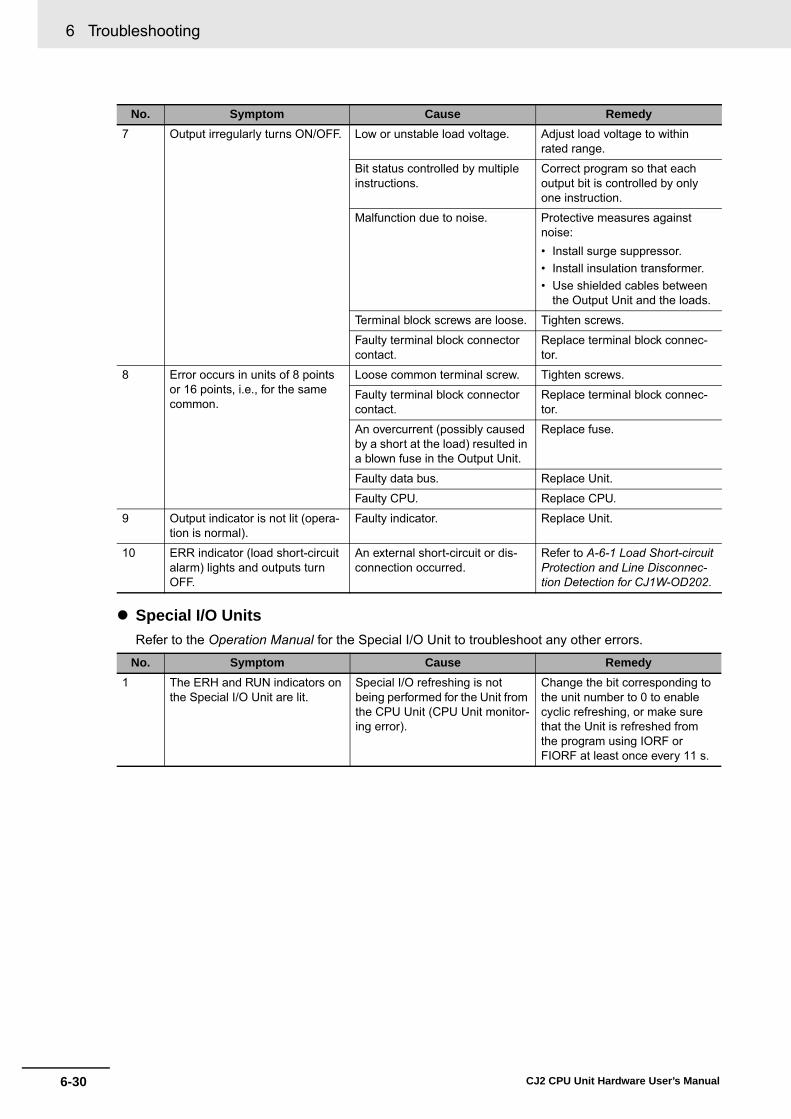
6 Troubleshooting
6-30 CJ2 CPU Unit Hardware User’s Manual
� Special I/O UnitsRefer to the Operation Manual for the Special I/O Unit to troubleshoot any other errors.
7 Output irregularly turns ON/OFF. Low or unstable load voltage. Adjust load voltage to within rated range.
Bit status controlled by multiple instructions.
Correct program so that each output bit is controlled by only one instruction.
Malfunction due to noise. Protective measures against noise:• Install surge suppressor.• Install insulation transformer.• Use shielded cables between
the Output Unit and the loads.
Terminal block screws are loose. Tighten screws.
Faulty terminal block connector contact.
Replace terminal block connec-tor.
8 Error occurs in units of 8 points or 16 points, i.e., for the same common.
Loose common terminal screw. Tighten screws.
Faulty terminal block connector contact.
Replace terminal block connec-tor.
An overcurrent (possibly caused by a short at the load) resulted in a blown fuse in the Output Unit.
Replace fuse.
Faulty data bus. Replace Unit.
Faulty CPU. Replace CPU.
9 Output indicator is not lit (opera-tion is normal).
Faulty indicator. Replace Unit.
10 ERR indicator (load short-circuit alarm) lights and outputs turn OFF.
An external short-circuit or dis-connection occurred.
Refer to A-6-1 Load Short-circuit Protection and Line Disconnec-tion Detection for CJ1W-OD202.
No. Symptom Cause Remedy1 The ERH and RUN indicators on
the Special I/O Unit are lit.Special I/O refreshing is not being performed for the Unit from the CPU Unit (CPU Unit monitor-ing error).
Change the bit corresponding to the unit number to 0 to enable cyclic refreshing, or make sure that the Unit is refreshed from the program using IORF or FIORF at least once every 11 s.
No. Symptom Cause Remedy

6-31
6 Troubleshooting
CJ2 CPU Unit Hardware User’s Manual
6-3 Non-C
PU U
nit Errors and Rem
edies
6
6-3-1 Error C
auses and Rem
edies
Use the following procedure if the CX-Programmer cannot be connected.
� Connecting via the Peripheral (USB) Port
CX-Programmer Connections
The CX-Programmer cannot connect.
Is the USB cable securely
connected?
No
No
No
No
Insert the cable all the way in at both the personal computer and at the CPU Unit.
Yes
Yes
Yes
Yes
Can the CX-Programmer be connected online?
End
Is the CX-Programmernetwork type set
to USB?
Set the CX-Programmer network type to USB.
Can the CX-Programmer be connected online?
Replace the USB cable.

6 Troubleshooting
6-32 CJ2 CPU Unit Hardware User’s Manual
� Connection to the EtherNet/IP Port (CJ2H-CPU6@-EIP and CJ2M-CPU3@ Only)
The CX-Programmer cannot connect.
Is the Ethernet cable securely connected?
At the personal computer (or the switching hub) and the CPU Unit, firmly insert the cable until the connector locks. Confirm that the LINK indicator lights at the personal computer (or switching hub) and that the 100M (10M) indicator lights at the CPU Unit.
Use the ping command from the personal computer to confirm that the communications to the PLC have been established. For details, refer to the EtherNet/IP Unit Operation Manual(Cat. No. W465).
Can the CX-Programmer be connected online?
Is a switching hub used between the personal computer
and the PLC?
If a personal computer is connected to a PLC using Straight Cable (or Cross Cable), it can occasionally be difficult to make the connection. If this occurs, try using a switching hub between the computer and PLC.
Use the ping command from the personal computer to confirm that the communications to the PLC is established. For details, refer to the EtherNet/IP Unit Operation Manual (Cat. No. W465).
Can the CX-Programmer
be connected online?
Are unique IP addresses used for the personal computer and the CPU Unit, and are they set for the same
domain?
Set the IP address for the personal computer. Either use the default IP address for the CPU Unit or else connect the CX-Programmer and set another IP address.
Use the ping command from the personal computer to confirm that the communications to the PLC has been established. For details, refer to the EtherNet/IP Unit Operation Manual (Cat. No. W465).
Can the CX-Programmer be connected online?
Is the CX-Programmer
network type set to EtherNet/IP?
Set the CX-Programmer network type to EtherNet/IP.
Can the CX-Programmer be connected online?
Replace the Ethernet cable and the switching hub.
No
Yes
End
Yes
Yes
Yes
Yes
Yes
No
No
No
No
No
No Yes
Yes
No
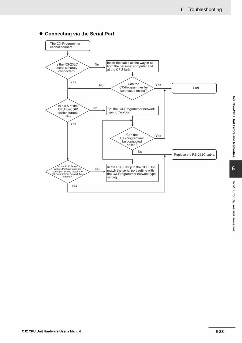
6-33
6 Troubleshooting
CJ2 CPU Unit Hardware User’s Manual
6-3 Non-C
PU U
nit Errors and Rem
edies
6
6-3-1 Error C
auses and Rem
edies
� Connecting via the Serial Port
No
Yes
End
Yes
Yes
Yes
No
No
No
No
Yes
The CX-Programmer cannot connect.
Is the RS-232C cable securely
connected?
Insert the cable all the way in at both the personal computer and at the CPU Unit.
Can the CX-Programmer be connected online?
Is pin 5 of the CPU Unit DIP switch turned
ON?
Set the CX-Programmer network type to Toolbus.
Can the CX-Programmer
be connected online?
Replace the RS-232C cable.
In the PLC Setup in the CPU Unit, does the
serial port setting match the CX-Programmer network type
setting?
In the PLC Setup in the CPU Unit, match the serial port setting with the CX-Programmer network type setting.

6 Troubleshooting
6-34 CJ2 CPU Unit Hardware User’s Manual

7-1CJ2 CPU Unit Hardware User’s Manual
7
This section describes the inspection and maintenance that is required for CJ2 PLCs.
7-1 Inspections . . . . . . . . . . . . . . . . . . . . . . . . . . . . . . . . . . . . . . . . . . . . . . . . . . . 7-27-1-1 Inspection Points . . . . . . . . . . . . . . . . . . . . . . . . . . . . . . . . . . . . . . . . . . . . . . . 7-27-1-2 Unit Replacement Precautions . . . . . . . . . . . . . . . . . . . . . . . . . . . . . . . . . . . . 7-4
7-2 Replacing the Battery . . . . . . . . . . . . . . . . . . . . . . . . . . . . . . . . . . . . . . . . . . 7-57-2-1 Battery Replacement . . . . . . . . . . . . . . . . . . . . . . . . . . . . . . . . . . . . . . . . . . . . 7-57-2-2 Operation When Battery Is Exhausted or Not Installed . . . . . . . . . . . . . . . . . . 7-8
7-3 Power Supply Unit Replacement Time . . . . . . . . . . . . . . . . . . . . . . . . . . . . 7-10
Inspection and Maintenance
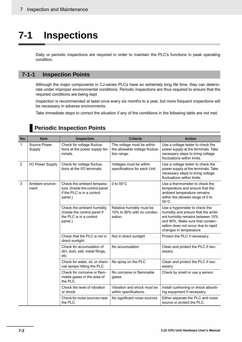
7 Inspection and Maintenance
7-2 CJ2 CPU Unit Hardware User’s Manual
7-1 Inspections
Daily or periodic inspections are required in order to maintain the PLC's functions in peak operatingcondition.
Although the major components in CJ-series PLCs have an extremely long life time, they can deterio-rate under improper environmental conditions. Periodic inspections are thus required to ensure that therequired conditions are being kept.
Inspection is recommended at least once every six months to a year, but more frequent inspections willbe necessary in adverse environments.
Take immediate steps to correct the situation if any of the conditions in the following table are not met.
7-1-1 Inspection Points
Periodic Inspection Points
No. Item Inspection Criteria Action1 Source Power
SupplyCheck for voltage fluctua-tions at the power supply ter-minals.
The voltage must be within the allowable voltage fluctua-tion range.
Use a voltage tester to check the power supply at the terminals. Take necessary steps to bring voltage fluctuations within limits.
2 I/O Power Supply Check for voltage fluctua-tions at the I/O terminals.
Voltages must be within specifications for each Unit.
Use a voltage tester to check the power supply at the terminals. Take necessary steps to bring voltage fluctuations within limits.
3 Ambient environ-ment
Check the ambient tempera-ture. (Inside the control panel if the PLC is in a control panel.)
0 to 55°C Use a thermometer to check the temperature and ensure that the ambient temperature remains within the allowed range of 0 to 55°C.
Check the ambient humidity. (Inside the control panel if the PLC is in a control panel.)
Relative humidity must be 10% to 90% with no conden-sation.
Use a hygrometer to check the humidity and ensure that the ambi-ent humidity remains between 10% and 90%. Make sure that conden-sation does not occur due to rapid changes in temperature.
Check that the PLC is not in direct sunlight.
Not in direct sunlight Protect the PLC if necessary.
Check for accumulation of dirt, dust, salt, metal filings, etc.
No accumulation Clean and protect the PLC if nec-essary.
Check for water, oil, or chem-ical sprays hitting the PLC.
No spray on the PLC Clean and protect the PLC if nec-essary.
Check for corrosive or flam-mable gases in the area of the PLC.
No corrosive or flammable gases
Check by smell or use a sensor.
Check the level of vibration or shock.
Vibration and shock must be within specifications.
Install cushioning or shock absorb-ing equipment if necessary.
Check for noise sources near the PLC.
No significant noise sources Either separate the PLC and noise source or protect the PLC.
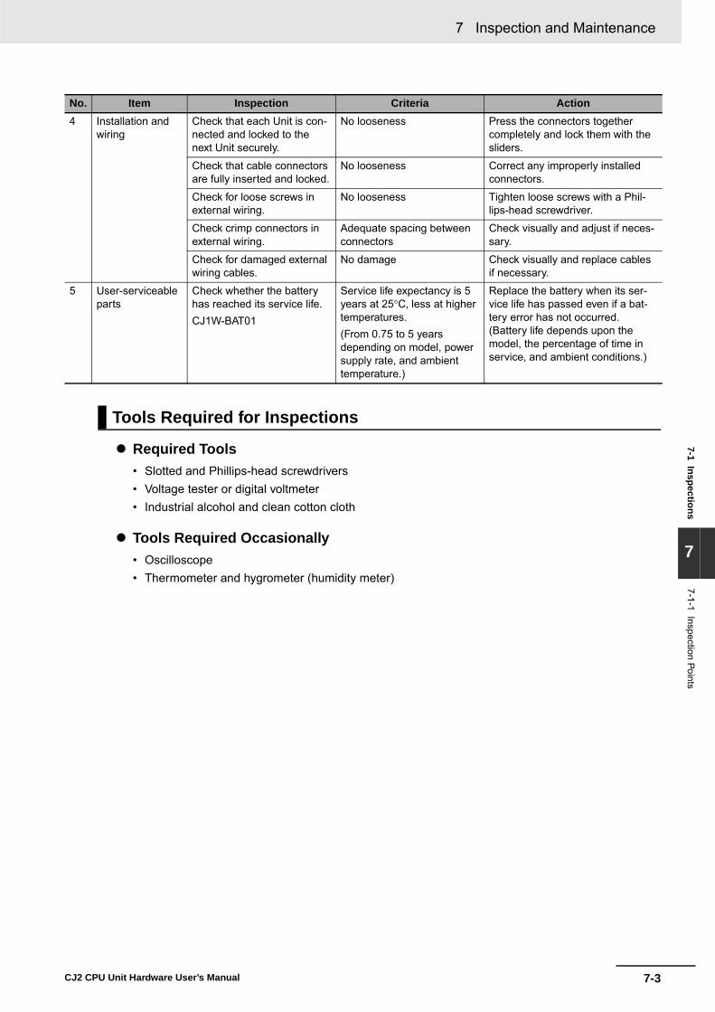
7-3
7 Inspection and Maintenance
CJ2 CPU Unit Hardware User’s Manual
7-1 Inspections
7
7-1-1 Inspection Points
� Required Tools• Slotted and Phillips-head screwdrivers• Voltage tester or digital voltmeter• Industrial alcohol and clean cotton cloth
� Tools Required Occasionally• Oscilloscope• Thermometer and hygrometer (humidity meter)
4 Installation and wiring
Check that each Unit is con-nected and locked to the next Unit securely.
No looseness Press the connectors together completely and lock them with the sliders.
Check that cable connectors are fully inserted and locked.
No looseness Correct any improperly installed connectors.
Check for loose screws in external wiring.
No looseness Tighten loose screws with a Phil-lips-head screwdriver.
Check crimp connectors in external wiring.
Adequate spacing between connectors
Check visually and adjust if neces-sary.
Check for damaged external wiring cables.
No damage Check visually and replace cables if necessary.
5 User-serviceable parts
Check whether the battery has reached its service life.CJ1W-BAT01
Service life expectancy is 5 years at 25°C, less at higher temperatures.(From 0.75 to 5 years depending on model, power supply rate, and ambient temperature.)
Replace the battery when its ser-vice life has passed even if a bat-tery error has not occurred. (Battery life depends upon the model, the percentage of time in service, and ambient conditions.)
Tools Required for Inspections
No. Item Inspection Criteria Action

7 Inspection and Maintenance
7-4 CJ2 CPU Unit Hardware User’s Manual
Check the following after replacing any faulty Unit.• Do not replace a Unit until the power is turned OFF.• Check the new Unit to make sure that there are no errors.• If a faulty Unit is being returned for repair, describe the problem in as much detail as possible,
enclose this description with the Unit, and return the Unit to your OMRON representative.• For poor contact, take a clean cotton cloth, soak the cloth in industrial alcohol, and carefully wipe the
contacts clean. Be sure to remove any lint prior to remounting the Unit.
Precautions for Correct UsePrecautions for Correct Use
• When replacing a CPU Unit, be sure that not only the user program but also all other datarequired for operation is transferred to or set in the new CPU Unit before starting operation,including DM Area and HR Area settings. If data area and other data are not correct for theuser program, unexpected accidents may occur.
• Be sure to include the routing tables, Controller Link Unit data link tables, network parameters,and other CPU Bus Unit data, which are stored as parameters in the CPU Unit. Be sure to setthis data again after replacing the CPU Unit.
• Refer to the CPU Bus Unit and Special I/O Unit operation manuals for details on the datarequired by each Unit.
Additional Information
The simple backup operation can be used to store the user program and all parameters for theCJ2 CPU Unit, DeviceNet Units, Serial Communications Units, and other specific Units in aMemory Card as backup files. A Memory Card and the simple backup operation can be used toeasily restore data after replacing any of these Units.
Refer to 8-3-6 Data Backed Up Using Simple Backup for details.
7-1-2 Unit Replacement Precautions

7-5
7 Inspection and Maintenance
CJ2 CPU Unit Hardware User’s Manual
7-2 Replacing the B
attery
7
7-2-1 Battery R
eplacement
7-2 Replacing the Battery
The Battery in the CJ-series CPU Unit must be replaced periodically as preventative maintenance. (TheBattery is a backup power supply for the CPU Unit's internal clock and RAM). This section describeshow to replace the Battery.
The Battery maintains the CPU Unit internal clock and the I/O memory data held in RAM while the mainpower supply is OFF. If the Battery is not installed or Battery voltage drops too low, the internal clock willstop and the I/O memory data that is held will be lost when the main power supply goes OFF.
At 25°C, the maximum service life for batteries is five years whether or not power is supplied to the CPUUnit while the battery is installed. The battery's lifetime will be shorter when it is used at higher temper-atures and when power is not supplied to the CPU Unit for long periods.
The following table shows the approximate minimum lifetimes and typical lifetimes for the backup bat-tery (total time with power not supplied).
*1 The minimum lifetime is the memory backup time at an ambient temperature of 55°C. The typical lifetime is thememory backup time at an ambient temperature of 25°C.
7-2-1 Battery Replacement
Purpose of the Battery
Battery Service Life and Replacement Period
Model Approx. maximum lifetime Approx. minimum lifetime*1 Typical lifetime*1
CJ2H-CPU6@(-EIP)CJ2M-CPU@@
5 years 1 year 2 months 5 years
Memory Backup Time
5 yr
4 yr
3 yr
2 yr
1 yr
Ambient temperature
This graphic is for reference only.
25°C 40°C 55°C
1 year 2 months
CJ2H-CPU6@(-EIP)
CJ2M-CPU@@
4 year 5 months
3 year 7 months

7 Inspection and Maintenance
7-6 CJ2 CPU Unit Hardware User’s Manual
If the PLC Setup has been set to detect a low-battery error, the ERR/ALM indicator on the front of theCPU Unit will flash when the battery is nearly discharged.
If the Battery Error Flag (A402.04) is ON*1, first check whether the Battery is properly connected to theCPU Unit. If the battery is properly connected, replace the battery as soon as possible.
Once a low-battery error has been detected, it will take 5 days (at an ambient temperature of 25°C*2)before the battery fails assuming that power has been supplied at least once a day. Battery failure andthe resulting loss of data in RAM can be delayed by ensuring that the CPU Unit power is not turnedOFF until the battery has been replaced.*1 The Battery Error Flag (A402.04) will turn ON only if the Detect Low Battery parameter in the PLC Setup has
been set to detect a low-battery error. If this setting has not been made, battery errors will not be detected. *2 The battery will discharge faster at higher temperatures, e.g., 4 days at 40°C and 2 days at 55°C.
� Replacement BatteryUse the CJ1W-BAT01 Battery Set.
Precautions for Correct UsePrecautions for Correct Use
Be sure to install a replacement battery within two years of the production date shown on thebattery's label.
Use the following procedure to replace the battery when the previous battery has become completelydischarged.
Precautions for Safe Use
We recommend replacing the battery with the power OFF to prevent the CPU Unit's sensitiveinternal components from being damaged by static electricity. The battery can be replaced with-out turning OFF the power supply. To do so, always touch a grounded piece of metal to dischargestatic electricity from your body before starting the procedure.
After replacing the battery, connect a Programming Device and clear the battery error.
1 Turn OFF the power to the CPU Unit.If the CPU Unit has not been ON, turn it ON for at least five minutes and then turn it OFF.
Low Battery Indicators
Replacement Procedure
ERR/ALMRUN
COMM
INHPRPHL
BKUP
CJ1W-BAT0108-06
Production Date
Manufactured in June 2008.

7-7
7 Inspection and Maintenance
CJ2 CPU Unit Hardware User’s Manual
7-2 Replacing the B
attery
7
7-2-1 Battery R
eplacement
Additional Information
If power is not turned ON for at least five minutes before replacing the battery, the capacitor thatbacks up memory when the battery is removed will not be fully charged and memory may be lostbefore the new battery is inserted.
2 Open the compartment on the upper left of the CPU Unit and carefully draw out the battery.
Precautions for Safe Use
• You must complete this procedure within five minutes at 25°C after turning OFF the power tothe CPU Unit to ensure memory backup. Data may be lost if more than five minutes isrequired.
• Never short-circuit the battery terminals; never charge the battery; never disassemble the bat-tery; and never heat or incinerate the battery. Doing any of these may cause the battery toleak, burn, or rupturing resulting in injury, fire, and possible loss of life or property. Also, neveruse a battery that has been dropped on the floor or otherwise subject to shock. It may leak.
• UL standards require that batteries be replaced by experienced technicians. Always place anexperienced technician in charge or battery replacement.
• Turn ON the power after replacing the battery for a CPU Unit that has been unused for a longtime. Leaving the CPU Unit unused again without turning ON the power even once after thebattery is replaced may result in a shorter battery life.
Additional Information
The battery error will be cleared automatically the next time the CPU Unit is turned ON afterreplacing the Battery.
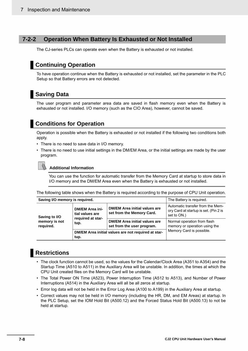
7 Inspection and Maintenance
7-8 CJ2 CPU Unit Hardware User’s Manual
The CJ-series PLCs can operate even when the Battery is exhausted or not installed.
To have operation continue when the Battery is exhausted or not installed, set the parameter in the PLCSetup so that Battery errors are not detected.
The user program and parameter area data are saved in flash memory even when the Battery isexhausted or not installed. I/O memory (such as the CIO Area), however, cannot be saved.
Operation is possible when the Battery is exhausted or not installed if the following two conditions bothapply.• There is no need to save data in I/O memory.• There is no need to use initial settings in the DM/EM Area, or the initial settings are made by the user
program.
Additional Information
You can use the function for automatic transfer from the Memory Card at startup to store data inI/O memory and the DM/EM Area even when the Battery is exhausted or not installed.
The following table shows when the Battery is required according to the purpose of CPU Unit operation.
• The clock function cannot be used, so the values for the Calendar/Clock Area (A351 to A354) and theStartup Time (A510 to A511) in the Auxiliary Area will be unstable. In addition, the times at which theCPU Unit created files on the Memory Card will be unstable.
• The Total Power ON Time (A523), Power Interruption Time (A512 to A513), and Number of PowerInterruptions (A514) in the Auxiliary Area will all be all zeros at startup.
• Error log data will not be held in the Error Log Area (A100 to A199) in the Auxiliary Area at startup.• Correct values may not be held in I/O memory (including the HR, DM, and EM Areas) at startup. In
the PLC Setup, set the IOM Hold Bit (A500.12) and the Forced Status Hold Bit (A500.13) to not beheld at startup.
7-2-2 Operation When Battery Is Exhausted or Not Installed
Continuing Operation
Saving Data
Conditions for Operation
Saving I/O memory is required. The Battery is required.
Saving to I/O memory is not required.
DM/EM Area ini-tial values are required at star-tup.
DM/EM Area initial values are set from the Memory Card.
Automatic transfer from the Mem-ory Card at startup is set. (Pin 2 is set to ON.)
DM/EM Area initial values are set from the user program.
Normal operation from flash memory or operation using the Memory Card is possible. DM/EM Area initial values are not required at star-
tup.
Restrictions

7-9
7 Inspection and Maintenance
CJ2 CPU Unit Hardware User’s Manual
7-2 Replacing the B
attery
7
7-2-2 Operation W
hen Battery Is E
xhausted or Not Installed
• The value for the Output OFF Bit (A500.15) will become unstable. Moreover, when the Output OFFBit turns ON, the outputs of all Output Units will turn OFF. To prevent the outputs of all Output Unitsfrom turning OFF at startup, take countermeasures such as writing the following program section intothe ladder program.
• Bank 0 will be the EM current bank at startup.• Files will not be held in the EM file memory (EM data converted to flash memory) and the file memory
function cannot be used. Make the EM file memory setting again in the PLC Setup, and format theEM file memory.
The following flowchart shows the flow of setup operations for the CPU Unit.
Setup Method
RSETA500.15
First Cycle Flag (A200.11)
CIO/W/TIM CNT/H/DM/EM
CNT/HR/DM/EM
Power ON
Operation with Battery
Is it necessary to hold the values of I/O
memory data for the next startup?
Yes Which data is required?
Operation without Battery
Are I/O memory initial values
required for program execution?
No
Yes
No
Can the I/O memory initial
values be set by the program?
No
The initial values are set in the user program.
Yes
Normal Operation (Memory Card Not Required)PLC Setup: Detect Low BatteryIOM Hold Bit: HoldA500.12 (IOM Hold Bit): ON
Normal Operation (Memory Card Not Required)PLC Setup: Detect Low Battery
Normal Operation (Memory Card Not Required, and User Program and Parameter Area Data Held in Flash Memory) PLC Setup: Do Not Detect Low Battery
Are the DM Area settings (D20000 to
D32767) for Special I/O Units and Inner Boards
the only initial values that are required?
Automatic Transfer at Startup (Memory Card Required)Transferred files: AUTOEXEC.OBJ,AUTOEXEC.STD,AUTOEXEC.IOMPLC Setup: Do Not Detect Low Battery
DM Area beginning with D00000, or EM Area
No Automatic Transfer at Startup (Memory Card Required)Transferred files: AUTOEXEC.OBJ, AUTOEXEC.STD,ATEXECDM.IOM, etc.PLC Setup: Do Not Detect Low Battery
Operation is not possible without a Battery.Other than the above.
Yes

7 Inspection and Maintenance
7-10 CJ2 CPU Unit Hardware User’s Manual
7-3 Power Supply Unit Replacement Time
The Power Supply Unit has a built-in electrolytic capacitor. The electrolytic capacitor is impregnatedwith electrolytic solution that starts to penetrate the sealing rubber from the time of manufacture. Astime elapses, the internal electrolytic solution continues to evaporate, resulting in decreased electro-static capacity and deterioration in other characteristics. Over time, the characteristic deterioration ofthe electrolytic capacitor prevents the Power Supply Unit from being utilized to its full capacity. In partic-ular, the speed at which the electrolytic capacitor deteriorates fluctuates greatly with the ambient tem-perature (generally, a temperature rise of 10°C will double the rate of a reaction, as stated by Arrhenius'law).
The CJ1W-PA205C Power Supply Unit with Replacement Notification monitors the internal temperatureof the Power Supply Unit while the power is turned ON, and calculates the level of deterioration of theelectrolytic capacitor from the operating time and internal temperature. The replacement notificationfunction displays the approximate time until the Power Supply Unit will stop functioning at its full capac-ity due to the characteristic deterioration of the electrolytic capacitor, based on the calculated level ofdeterioration. When 6 months are remaining until replacement is required, the alarm output will turnOFF.
Note The replacement notification function provides an indication of when the deterioration of the electrolyticcapacitor will prevent the power supply functioning at its full capacity. It does not provide information on fail-ures occurring due to other causes.
� CJ1W-PA205C
Principle of Replacement Notification
Power Supply Unit with Replacement Notification
Model SpecificationsCJ1W-PA205C 100 to 240 VAC, Output capacity: 5 A at 5 VDC, 0.8 A at 24 VDC, total of 30 W
With replacement notification
Power Supply Unit Replacement Notification Module
CJ1W-PA205C POWER
TEST
ALARM OUTPUTDC30V, 50mANORMAL:ONALARM OFF
L
Replacement notification display (7-segment, red)
POWER indicator (green)
Alarm output (replacement notification output)test switch
Alarm output (replacement notification output)wiring diagram

7-11
7 Inspection and Maintenance
CJ2 CPU Unit Hardware User’s Manual
7-3 Power Supply U
nit Replacem
ent Time
7
� Replacement Notification Function DisplaysThe replacement notification of the Power Supply Unit is shown using three 7-segment display char-acters.• At time of purchase “FUL” is displayed. The display changes to “HLF” as the electrolytic capacitor
deteriorates (“HLF” may not be displayed, depending on the operating environment).• When the time until replacement is required drops below 2 years, the display will change corre-
sponding to the operating time from “1.5” to “1.0” to “0.5” to “0.0”/”A02.” When the remaining ser-vice life reaches 6 months or less, the display will alternate between “0.0” and “A02” in 2-secondintervals.
Note 1 The time remaining until replacement does not include periods when the power is turned OFF.2 Until approximately one month of operating time has accumulated, the display will always be “ful” and the
alarm output will remain ON (conducting) due to the estimated deterioration speed.3 The time remaining until replacement will vary the operating and storage conditions, so periodically check
the display.4 Fluctuation in the time remaining until replacement may result in the alarm output repeatedly turning ON
and OFF.5 The precision of the replacement notification function will be adversely affected by applications in which
the power is frequently turned ON and OFF.6 Due to the service life of the electronic components, replace the Power Supply Unit approximately 15
years after purchase, even if the replacement notification display or output has not indicated that replace-ment is required.
� Alarm Output (Replacement Notification Output)The output remains ON until the remaining service life drops below 6 months and then turns OFF.
Note The alarm output will also turn OFF under the following conditions.• The AC input to the Power Supply Unit is turned OFF.• An error is detected by the self-diagnostic function.• The TEST switch is pressed for at least 3 seconds.
Function
Capacity at time of manufacture
Replacementrequired
Electrolyticcapacitor level Replacement notification
display (7-Segment)2.0 yr 1.5 yr 1.0 yr 0 yr Remaining
life spanAlarm output (replacement notification output)
Output ONOutputOFF
The output turns OFF when the remaining life span reaches 6 months, and the following display is repeatedly alternated.
0.5 yr

7 Inspection and Maintenance
7-12 CJ2 CPU Unit Hardware User’s Manual
Additional Information
Example of Using the Alarm Output:
Monitoring Power Supply Replacement Notification in the System (6 Months or Less UntilReplacement Is Required)
The Flag is programmed to allow for the delay in the alarm output at system startup. The Flagdoes not turn ON when the alarm output is ON (normal operation). When the alarm output turnsOFF (replacement required), the Flag turns ON, and the replacement notification can be moni-tored from the system.
� Maintenance Function Using the TEST Switch• Press the TEST switch for at least 3 seconds to display “A02” and force the alarm output OFF.
Release the switch to return to normal operating status.The TEST switch is used initially or periodically to check the connection status between the alarmoutput and external devices.
• Press the TEST switch for less than 3 seconds to display the unit version information for thePower Supply Unit.
Precautions for Correct UsePrecautions for Correct Use
• Replace the Power Supply Unit within 6 months when the display on the front panel of thePower Supply Unit alternates between 0.0 and A02 or the alarm output automatically turnsOFF.
• Maintain an ambient storage temperature of −20 to 30°C and humidity of 25% to 70% whenstoring the product (with the power turned OFF) for longer than 3 months to keep the replace-ment notification function in optimum working condition. The replacement time is calculatedfrom when the power is turned ON only. The precision of the replacement period will decline ifthe electrolytic capacitor deteriorates during storage.
� Normal Display: Replacement Notification DisplayWhen 6 months or less are remaining until replacement is required, the display will alternatebetween “0.0” and “A02” (in 2 second intervals), and the alarm output will turn OFF.
Display and Alarm Output Operation
T000
TIM 000 5 s
ON
OFF
Alarm output
Turns OFF when 6 months remains
Alarm output
Internal Flag
ON OFF
Remaining service life: 1 year to 6 months Remaining service life: 6 months max.
Alarm output
2 s 2 s 2 s 2 s 2 s

7-13
7 Inspection and Maintenance
CJ2 CPU Unit Hardware User’s Manual
7-3 Power Supply U
nit Replacem
ent Time
7
� Operation When Turning ON the PowerThe following initial display is shown when the power is turned ON, after which the replacement noti-fication is displayed. The alarm output turns ON approximately 0.2 seconds after the power is turnedON.
When replacement is already required, the alarm display will follow the initial display. The alarm out-put will turn ON approximately 0.2 seconds after the power is turned ON, and then turn OFF afterapproximately 5 seconds.
� Operation at Power OFFWhen the power is turned OFF, the display will turn OFF after the PLC operation stops. The alarmoutput will turn OFF after the display turns OFF.
*1 The values shown are reference values (calculated for a no-load status on the Power Supply Unit's output).
If replacement is already required, the display will turn OFF after the PLC operation stops. When thedisplay turns OFF, the alarm output will turn ON momentarily and then turn OFF again.
*1 The values shown are reference values (calculated for a no-load status on the Power Supply Unit's output).
ONOFF
Power ON
DisplayAlarm output
Display start
1 s max.
0.2 s max.
Initial display (approx. 1.1 s) Replacementrequired display0.3 s 0.1 s 0.3 s 0.1 s 0.3 s
OFFONOFF
Power ON
Display
Alarm output
1 s max.0.2 s max.
Display start Initial display (approx. 1.1 s)
Alarm display
Alarm output OFF
5 s max.
ON OFF
OFF
Display
Alarm output
Replacementnotification display
Power interruption
PLC operation stopped Notification display
Approx. 70 ms*1
Alarm output
100 VAC: Approx. 2 s200 VAC: Approx. 7 s*1
OFF OFF
OFF
ON
Display
Alarm output
Alarm display
Power interruption
PLC operation stopped
Notification display OFF + alarm output ON Alarm output
Approx. 70 ms*1
100 VAC: Approx. 2 s200 VAC: Approx. 7 s*1
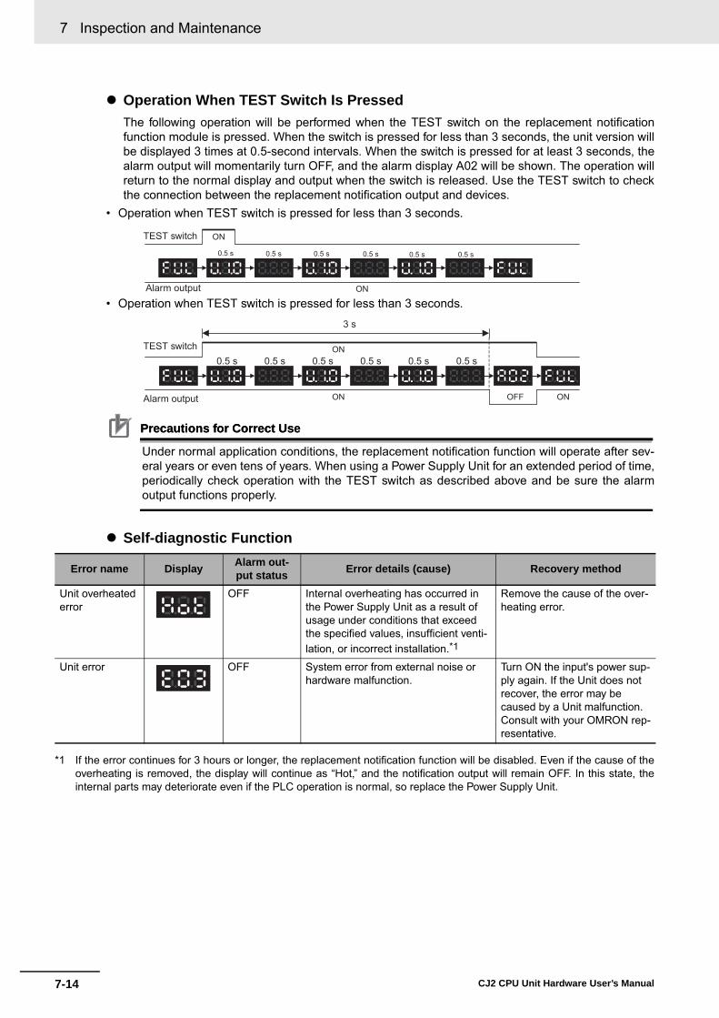
7 Inspection and Maintenance
7-14 CJ2 CPU Unit Hardware User’s Manual
� Operation When TEST Switch Is PressedThe following operation will be performed when the TEST switch on the replacement notificationfunction module is pressed. When the switch is pressed for less than 3 seconds, the unit version willbe displayed 3 times at 0.5-second intervals. When the switch is pressed for at least 3 seconds, thealarm output will momentarily turn OFF, and the alarm display A02 will be shown. The operation willreturn to the normal display and output when the switch is released. Use the TEST switch to checkthe connection between the replacement notification output and devices.
• Operation when TEST switch is pressed for less than 3 seconds.
• Operation when TEST switch is pressed for less than 3 seconds.
Precautions for Correct UsePrecautions for Correct Use
Under normal application conditions, the replacement notification function will operate after sev-eral years or even tens of years. When using a Power Supply Unit for an extended period of time,periodically check operation with the TEST switch as described above and be sure the alarmoutput functions properly.
� Self-diagnostic Function
*1 If the error continues for 3 hours or longer, the replacement notification function will be disabled. Even if the cause of theoverheating is removed, the display will continue as “Hot,” and the notification output will remain OFF. In this state, theinternal parts may deteriorate even if the PLC operation is normal, so replace the Power Supply Unit.
Error name Display Alarm out-put status Error details (cause) Recovery method
Unit overheated error
OFF Internal overheating has occurred in the Power Supply Unit as a result of usage under conditions that exceed the specified values, insufficient venti-lation, or incorrect installation.*1
Remove the cause of the over-heating error.
Unit error OFF System error from external noise or hardware malfunction.
Turn ON the input's power sup-ply again. If the Unit does not recover, the error may be caused by a Unit malfunction. Consult with your OMRON rep-resentative.
ON
ON
TEST switch
Alarm output
0.5 s 0.5 s 0.5 s 0.5 s 0.5 s 0.5 s
ON
ON OFF ON
0.5 s 0.5 s 0.5 s 0.5 s 0.5 s 0.5 sTEST switch
Alarm output
3 s

7-15
7 Inspection and Maintenance
CJ2 CPU Unit Hardware User’s Manual
7-3 Power Supply U
nit Replacem
ent Time
7
Comparison between the CJ1W-PA205C and CJ1W-PA205R
Item CJ1W-PA205C CJ1W-PA205R (for comparison)RUN contact output Not supported Supported
Terminal block arrangement
Terminal block position Located on the left side of the Unit. Located on the right side of the Unit.
POWER indicator On replacement notification module On hood of Power Supply Unit
Replacement notification Supported(7-segment display + transistor out-puts)
Not supported
NC
NC
L2/N
L1
100 to 240 VACINPUT
AC input
LG
Unconnectedterminals
GR
CJ1W-PA205C
L2/N
L1
24 VDC2A RESISTIVE
240 VACOUTPUT
RUN
INPUT100 to 240 VAC
AC input
LG
RUN output (RUN contact)
GR
CJ1W-PA205R
Years
POWERCJ1W-PA205C
TEST
NC
NC
AC100-240VINPUT
L2/N
L1
L+
ALARMOUTPUTDC30V,50mA
NORMAL:ONALARM :OFF
Terminal block Alarm output terminals
POWER
PA205R
DC24VAC240V
OUTPUTRUN
INPUTAC100-240V
L2/N
L1
Terminal block

7 Inspection and Maintenance
7-16 CJ2 CPU Unit Hardware User’s Manual

8-1CJ2 CPU Unit Hardware User’s Manual
8
This section describes operations used to back up and restore data.
8-1 Backing Up Data . . . . . . . . . . . . . . . . . . . . . . . . . . . . . . . . . . . . . . . . . . . . . . . 8-2
8-2 Using a Computer to Back Up Data . . . . . . . . . . . . . . . . . . . . . . . . . . . . . . . 8-38-2-1 PLC Backup Tool . . . . . . . . . . . . . . . . . . . . . . . . . . . . . . . . . . . . . . . . . . . . . . . 8-38-2-2 PLC Backup Tool Operations . . . . . . . . . . . . . . . . . . . . . . . . . . . . . . . . . . . . . . 8-4
8-3 Simple Backup . . . . . . . . . . . . . . . . . . . . . . . . . . . . . . . . . . . . . . . . . . . . . . . . 8-78-3-1 Overview . . . . . . . . . . . . . . . . . . . . . . . . . . . . . . . . . . . . . . . . . . . . . . . . . . . . . 8-78-3-2 Operating Procedures . . . . . . . . . . . . . . . . . . . . . . . . . . . . . . . . . . . . . . . . . . . 8-88-3-3 Verifying Backup Operations with Indicators . . . . . . . . . . . . . . . . . . . . . . . . . 8-108-3-4 Related Auxiliary Bits/Words . . . . . . . . . . . . . . . . . . . . . . . . . . . . . . . . . . . . . 8-128-3-5 Time Required for Simple Backup . . . . . . . . . . . . . . . . . . . . . . . . . . . . . . . . . 8-128-3-6 Data Backed Up Using Simple Backup . . . . . . . . . . . . . . . . . . . . . . . . . . . . . 8-12
Backup Operations

8 Backup Operations
8-2 CJ2 CPU Unit Hardware User’s Manual
8-1 Backing Up Data
There are two methods for backing up PLC data.
• Operation: PLC Backup Tool running on the personal computer• Backup destination: Computer hard disk
• Operation: DIP switch and Memory Card Power Switch• Backup destination: A Memory Card inserted in the CPU Unit
Using a Computer to Back Up Data to the Computer
Using Front-panel Switches on the CPU Unit to Back Up Data to a Memory Card
PLC Backup Tool
CPU Unit
Backup All PLC data
Memory CardAll PLC data
Backup
Back up data by pressing the Memory Card Power Switch.

8-3
8 Backup Operations
CJ2 CPU Unit Hardware User’s Manual
8-2 Using a C
omputer to B
ack Up D
ata
8
8-2-1 PLC
Backup Tool
8-2 Using a Computer to Back Up Data
The PLC Backup Tool can be used to back up, compare, and restore data, such as programs and unitparameters, of all the Units or of only specified Units in a PLC that is connected online.
� ApplicationsThe PLC Backup Tool can be used for the following applications. • Backing up all of the data from the PLC • Comparing all of the data in the PLC with the data backed up in the computer • Transferring all of the data to a PLC that has the same system configuration as another PLC • Transferring data to a Unit that has been replaced, e.g., when the Unit has failed
� Applicable Units
� Applicable Data
8-2-1 PLC Backup Tool
Applicable Unit DescriptionCPU Unit CS/CJ/CP-series PLCs, all models and all versions
Data in the following Units is not backed up: • Screen data for an NSJ Controller • SYSMAC SPU Unit data• Customizable Counter Unit data
Special I/O Units and CPU Bus Units
Refer to the list of backup Units in the help files for the PLC Backup Tool.
Applicable Unit DescriptionCPU Unit User program, symbols tables, rung comments, program index, parameters (PLC
Setup, registered I/O tables, routing tables, Ethernet settings, and all other data in the initial setting areas), I/O memory, forced status (backup and comparison only), and EM file memory data (backup only)
Special I/O Units and CPU Bus Units
Parameter settings and data stored inside the Unit (e.g., programming created with Support Software)
CJ2
Backup folderDefault name:C\Backup\yymmdd_hhmmss
PLC Backup Tool
CPU Unit + Configuration Units
(CPU Bus Units and Special I/O Units)Restore or Compare
Back up

8 Backup Operations
8-4 CJ2 CPU Unit Hardware User’s Manual
� RestrictionsThe following restrictions apply. • Forced Status
Forced status cannot be restored. If you attempt to restore forced status, the address of the force-set/reset bits will be displayed in the log display area. Use the CX-Programmer or Switch Box to man-ually force-set/reset the displayed bits.
• Data Stored in EM File Memory (Part of the EM Area Converted to File Memory) EM file memory cannot be compared or resorted. EM file memory backups are saved in the CPU\EM_FILES Folder that will be created within thebackup file destination folder. Restore EM file memory manually by using the PLC Memory Card Win-dow in the CX-Programmer to write the data to memory.
• Restrictions in Comparing and Restoring I/O Memory The CIO Area and Auxiliary Area data in the I/O memory cannot be compared or restored.
An overview of the PLC Backup Tool is provided below. For details on specific procedures and func-tions, refer to the CX-Programmer Operation Manual (Cat. No. W446).
� Starting the PLC Backup Tool Either of the following methods can be used to start the PLC Backup Tool.• Select PLC Backup Tool from the CX-Programmer Tools Menu. • Select Programs − OMRON− CX-One − CX Programmer − PLC Backup Tool from the Windows
Start Menu.
The PLC Backup Tool Dialog Box will be displayed.
8-2-2 PLC Backup Tool Operations

8-5
8 Backup Operations
CJ2 CPU Unit Hardware User’s Manual
8-2 Using a C
omputer to B
ack Up D
ata
8
8-2-2 PLC
Backup Tool O
perations
� Backing Up DataThe data in the connected PLC can be backed up to the computer as a batch. A folder named with thedate and time will be automatically created under the user-specified folder, and the backup files will becreated in that folder.
� Comparing Data Data in backup files can be compared with data from other backup files or data from connected PLC.The comparison results will be displayed.
Backup files can be restored after the comparison results have been displayed. Also, the comparisonresults can be saved in a CSV file.
All Units in the PLC are displayed here.Individual Units can be selected for backup.
Specify the source backup file on the computer.
Specify the target PLC or backup file to compare.PLC: The currently connected PLC will be
displayed as the target.File: Specify another backup file on the computer
as the target.

8 Backup Operations
8-6 CJ2 CPU Unit Hardware User’s Manual
� Restoring Data PLC data can be restored to a previous state by transferring backup file data to a connected PLC.Before the data is restored, a comparison will be made automatically with the applicable PLC and theresults will be displayed.
Before the data is restored, the contents of the data can be checked by starting the Support Softwarefor that Unit.
Precautions for Correct UsePrecautions for Correct Use
The CPU Unit will be changed to PROGRAM mode before restoring the data. This will stop oper-ation. Be sure it is safe to stop CPU Unit operation before restoring the data.
Precautions for Safe Use
• Sufficiently check the data that is selected for restoring before performing the next step. If thecorrect data is not restored, unexpected operation may occur in the controlled system after thedata is restored.
• Some Special I/O Units and CPU Bus Units operate with parameters that are stored in theCPU Unit. If one of these Units is selected for backup, restrictions will be displayed in the Com-ments Area of the Backup from PLC Dialog Box. Confirm the restrictions, and always selectthe Special I/O Unit or CPU Bus Unit together with the CPU Unit when backing up or restoringdata. If the data from both Units is not backed up or restored together, unexpected operationmay occur in the controlled system.
• If there are any backup restrictions for the Units to which data is being restored, the restric-tions will be displayed in the Comments Area of the Backup from PLC Dialog Box. Confirm therestrictions, and always take the required measures. If required measures are not taken, unex-pected operation may occur in the controlled system after the data is restored.
• Confirm that stopping PLC operation will not create any problems before restoring data duringPLC operation. If the PLC stops at an unanticipated time, unexpected operation may occur inthe controlled system.
• Always turn the power supply to the PLC OFF and then ON after restoring data. If the powersupply is not turned OFF and then ON, memory in the PLC may not be updated to the restoreddata, which may cause unexpected operation of the controlled system.
• Forced status can be backed up, but it cannot be restored. If you restored data that containedforced status, use the CX-Programmer after restoring the data to force-set or force-reset bitsas required. If required bits are not force-set or force-reset, differences in the forced status inmemory may cause unexpected operation of the controlled system.
@: Check boxes will appear for Units to which data can be restored.
Configuration: Indicates whether the configurations match between the backup file and the PLC.

8-7
8 Backup Operations
CJ2 CPU Unit Hardware User’s Manual
8-3 Simple B
ackup
8
8-3-1 Overview
8-3 Simple Backup
The simple backup operation can be used to back up all PLC data to a Memory Card, or to restore orcompare the data, by using a simple DIP switch setting and the Memory Card Power Supply Switch. NoSupport Software is required.
8-3-1 Overview
Backup operation DIP switch on front
of CPU Unit ProcedurePin 7
Backing up data to the Memory Card
ON Press the Memory Card Power Supply Switch for three sec-onds.
The data can be backed up regardless of the CPU Unit operating mode.
Restoring data from the Memory Card
Turn the PLC OFF and ON again. (Data restoration is given priority over the automatic transfer at startup.)
After the data has been restored, the operating mode will remain in PROGRAM mode until the PLC power is turned OFF.
Comparing data to the Memory Card
OFF Press the Memory Card Power Supply Switch for three sec-onds.
The data can be compared regardless of the CPU Unit operating mode.
1.
2.
Power Supply UnitTurn ON pin 7 on the DIP switch.
Memory Card
Backup
Backing Up Data
Press the Memory Card Power Supply Switch.
Memory Card Power Supply Switch
All PLC data, including the following data.Data in the CPU Unit:
User programsParametersI/O memorySymbol tables Comment files Program index file
Data in mounted Special I/O Units and CPU Bus Units
CPU Unit

8 Backup Operations
8-8 CJ2 CPU Unit Hardware User’s Manual
1 Insert the Memory Card into the CPU Unit. The MCPWR indicator will light and the BUSY indicator will flash (meaning the Memory Card isbeing accessed) and then turn OFF.
2 Turn ON pin 7 on the CPU Unit's DIP switch.
3 Press the Memory Card Power Supply Switch for three seconds until the BUSY indicator lights,and then release the switch.
The PLC will start backing up data to the Memory Card. The MCPWR indicator will flash onceand then light while the data is being written. At the same time the BUSY indicator will flash. TheMCPWR and BUSY indicators will both turn OFF when the operation is completed normally.
4 Turn OFF pin 7 on the CPU Unit's DIP switch.
1 Turn OFF the PLC power supply.
2 Insert the Memory Card containing the backup files into the CPU Unit.
3 Turn ON pin 7 on the CPU Unit's DIP switch.
4 Turn ON the PLC power supply.
The PLC will start restoring the data from the Memory Card. The MCPWR indicator will flashonce and then light while the data is being read. At the same time the BUSY indicator will flash.
The MCPWR and BUSY indicators will both turn OFF when the operation is completed normally.If the MCPWR indicator flashes five times, or if only the BUSY signal turns OFF, it means that anerror has occurred. (Refer to 8-3-3 Verifying Backup Operations with Indicators.)
5 Turn OFF pin 7 on the CPU Unit's DIP switch.
Note 1 The backup function will override the automatic transfer at startup function, so the backup files will be readto the CPU Unit when the PLC is turned ON even if pin 2 of the DIP switch is ON.
2 Data will not be read from the Memory Card to the CPU Unit if pin 1 of the DIP switch is ON (write-protect-ing program memory).
8-3-2 Operating Procedures
Backing Up Data from the CPU Unit to the Memory Card
Restoring Data from the Memory Card to the CPU Unit
Memory Card
Press the Memory Card Power Supply Switch for three seconds.
Pin 7: ON

8-9
8 Backup Operations
CJ2 CPU Unit Hardware User’s Manual
8-3 Simple B
ackup
8
8-3-2 Operating P
rocedures
Additional Information
• When the backup files are read from the Memory Card by the backup function, the status of I/O memory and force-set/force-reset bits will be cleared unless the necessary settings aremade in the Auxiliary Area and PLC Setup.If the IOM Hold Bit (A500.12) is ON and the PLC Setup is set to maintain the IOM Hold Bit Sta-tus at Startup when the backup files are written, the status of I/O memory data will be main-tained when data is read from the Memory Card.If the Forced Status Hold Bit (A500.13) is ON and the PLC Setup is set to maintain the ForcedStatus Hold Bit Status at Startup when the backup files are written, the status of force-set andforce-reset bits will be maintained when data is read from the Memory Card.
• After the simple backup operation has been used to restore data from the Memory Card to thePLC, the operating mode will remain in PROGRAM mode and cannot be changed to MONI-TOR or RUN mode until the PLC power is turned OFF. After restoring the data, turn OFF thepower, change the setting of DIP switch pin 7, and then turn the power back ON.
• File backups may take from several seconds to several minutes. For information on executiontimes refer to 8-3-5 Time Required for Simple Backup.
1 Insert the Memory Card containing the backup files into the CPU Unit.
The MCPWR indicator will light and the BUSY indicator will flash and then turn OFF.
2 Turn OFF pin 7 on the CPU Unit's DIP switch.
3 Press the Memory Card Power Supply Switch for three seconds until the BUSY indicator lights,and then release the switch.
The PLC will start comparing the data in the PLC and the data in the backup file on the MemoryCard. The MCPWR indicator will flash once and then light while the data is being written. At thesame time the BUSY indicator will flash.
The MCPWR and BUSY indicators will both turn OFF if the data matches. If the MCPWR andBUSY indicators both flash, it means that the data does not match or that an error has occurred.(Refer to 8-3-3 Verifying Backup Operations with Indicators.)
Note If an error occurs during writing or comparison, the MCPWR indicator will flash. Press the power supplyswitch to stop the flashing and to turn ON the MCPWR indicator.
Comparing Data in the Memory Card and CPU Unit
Memory Card
Press the Memory Card Power Supply Switch for three seconds.
Pin 7: OFF

8 Backup Operations
8-10 CJ2 CPU Unit Hardware User’s Manual
The status of the Memory Card Power (MCPWR) indicator shows whether a simple backup operationhas been completed normally or not.
8-3-3 Verifying Backup Operations with Indicators
Backup operation Normal completion*1 Error occurred
MCPWR status MCPWR status Error
Backing up data from the CPU Unit to the Memory Card
The data was not backed up due to one of the following errors, and no backup file was created.
• Insufficient Memory Card capacity • Memory error in CPU Unit • I/O bus error • Data was not read from the Unit to be backed up.
MCPWR Indicator OPEN
PERIPHERAL
BUSY
MCPWR
MCPWR
MCPWR
MCPWR
MCPWR
Lit
Remains lit while the Memory Card Power Switch is pressed.
Flashes once.
Lit while writing.
OFF after data is written.
MCPWR
MCPWR
Lit
Remains lit while the Memory Card Power Switch is pressed.
Remainsflashing.

8-11
8 Backup Operations
CJ2 CPU Unit Hardware User’s Manual
8-3 Simple B
ackup
8
8-3-3 Verifying Backup O
perations with
Indicators
*1 When the backup operation is completed normally, power to the Memory Card will go OFF when the MCPWR indicatorgoes OFF. If the Memory Card will be used again, press the Memory Card Power Switch to supply power and execute thedesired operation.
*2 The backup files for Units and Boards are also compared.
Restoring data from the Memory Card to the CPU Unit
The data was not restored due to one of the following causes.
• Program in Memory Card exceeds CPU Unit capacity • Required backup files do not exist in Memory Card. • Program can't be written because it is write-protected
(Pin 1 of the DIP switch is ON.) • The EM file was not complete, i.e., a portion was missing.• There are fewer CPU Unit EM banks than backup EM
files.
The I/O tables are not correct (e.g., the same unit number was set twice).
• A Unit was added to the configuration since the data was backed up.
• The unit number settings for Special I/O Units or CPU Bus Units are not correct.
A Unit was added to the configuration since the data was backed up.
Comparing data between the CPU Unit and the Memory Card
The following comparison errors can occur:
• Memory error in CPU Unit*2
• Incorrect I/O tables (e.g., the same unit number set twice)• Comparison results (of backup files on Memory Card and
data in PLC) do not match.
• Required backup files do not exist in Memory Card.*2
• I/O bus error
Backup operation Normal completion*1 Error occurred
MCPWR status MCPWR status Error
MCPWR
MCPWR
MCPWR
MCPWR
Lit when power is turned ON.
Flashes once.
Lit while reading.
OFF after data is read.
MCPWR
MCPWR
MCPWR
Lit when power is turned ON.
Flashes five times.
Goes OFF.
MCPWR
MCPWR
MCPWR
Lit when power is turned ON.
Flashes once.
Remains lit.
MCPWR
H8
Same as for normal completion.
Special I/O or CPU Bus Unit ERR indicator
7-segment LED indicator
Displayed as “H8”
MCPWR
INEE Board READYindicator
Flashing
Same as for normal completion.
MCPWR
MCPWR
MCPWR
MCPWR
Remains lit while the Memory Card Power Switch is pressed.
Lit
Flashes once.
Lit while comparing.
OFF after data is compared.
MCPWR
MCPWR
Lit
Remains lit while the Memory Card Power Switch is pressed.
Remains flashing.

8 Backup Operations
8-12 CJ2 CPU Unit Hardware User’s Manual
The following tables list the benchmark execution times for the simple backup operation. The executiontime will depend on the Unit configuration, cycle time, and Memory Card. These times were measuredunder the following conditions:
CPU Unit Model: CJ2H-CPU6@-EIP or CJ2M-CPU3@
Configuration: CPU Unit only
Operating mode: PROGRAM
Additional Information
The Units that are backed up for the simple backup operation are predetermined. You cannotspecify which Units are backed up and which are not.
The files and applicable data transferred between the Memory Card and CPU Unit using the simplebackup operation are listed below. The file name is fixed as BACKUP@@.
* CJ2H-CPU6@-EIP or CJ2M-CPU3@ only. Program files that include network symbols cannot be transferred to the CJ2H-CPU6@ or CJ2M-CPU1@. AMemory Card transfer error (fatal) will occur if an attempt is made to transfer such a file.
8-3-4 Related Auxiliary Bits/Words
Name Address Description File Memory Operation Flag
A343.13 ON when any of the following are being performed. OFF when execu-tion has been completed.• Memory Card detection• CMND instruction executed for local CPU Unit• FREAD/FWRIT instructions• Program replacement via special control bits• Simple backup operationWiring data to or verifying the contents of the Memory Card is not pos-sible while this flag is ON.
EM File Memory Starting Bank
A344 When the CPU Unit starts reading from the Memory Card, it references this value. If the maximum EM bank number of the [email protected] files (maximum consecutive bank number counting from 0) matches the maximum bank number of the CPU Unit, the EM area will be formatted based on the value in this word. If the maximum EM bank numbers do not match, the EM Area will revert to its unformatted condition.
8-3-5 Time Required for Simple Backup
Operating mode Writing to Memory Card Reading from Memory Card
User program: 120K steps, No network symbols (tags) Approx. 7 s Approx. 20 s
User program: 120K steps, 20,000 network symbols (tags) Approx. 19 s Approx. 68 s
8-3-6 Data Backed Up Using Simple Backup
Program Files
Contents Backup Restore Compare File name Extension• User program• Network symbols*
Yes Yes Yes BACKUP .OBJ

8-13
8 Backup Operations
CJ2 CPU Unit Hardware User’s Manual
8-3 Simple B
ackup
8
8-3-6 Data Backed U
p Using S
imple B
ackup
There are five types of data files, as shown below, when the simple backup operation is used for back-ing up data (creating files) on the Memory Card or for restoring or comparing data from the MemoryCard.• BACKUP.IOM• BKUPIOR.IOR• BACKUPDM.IOM• [email protected]• [email protected]
These files are used exclusively for the simple backup operation. With the exception of BKUPIOR.IOR,they can all be manipulated from the CX-Programmer. (BKUPIOR.IOR files cannot be manipulated.)
Symbol Tables, Comments, and Program Index Files
Contents Backup Restore Compare File name ExtensionSymbol table files Yes Yes Yes BKUPSYM .SYM
Comment files BKUPCMT .CMT
Program index file BKUPPRG .IDX
Parameter Files
Contents Backup Restore Compare File name Extension• PLC Setup• PLC name• Registered I/O tables• Routing tables• CPU Bus Unit setup• Etc.
Yes Yes Yes BACKUP .STD
Data
I/O memoryBackup Restore Compare File name Extension
Area Addresses
DM Area D00000 to D19999 Yes Yes No BACKUP .IOM
CIO Area CIO 0000 to CIO 6143(Includes forced sta-tus.)
Yes --- (See note 3.)
No BAUPIOR .IOR
Work Area W000 to W511(Includes forced sta-tus.)
Yes --- (See note 3.)
No
Holding Area H000 to H511 Yes Yes NoAuxiliary Area A000 to A447, A10000
to A11135Yes --- ---
A448 to A1472 Yes Yes NoTimer Completion Flags and Timer PVs
T0000 to T4095 Yes --- (See note 3.)
No
Counter Comple-tion Flags and Counter PVs
C0000 to C4095 Yes Yes No

8 Backup Operations
8-14 CJ2 CPU Unit Hardware User’s Manual
Note 1 If the number of banks in the EM data on the Memory Card is less than the number of EM banks in theCPU Unit where the data is to be restored (e.g., if data backed up by the CJ2H-CPU64-EIP is to berestored at the CJ2H-CPU68-EIP), the amount of EM data on the Memory Card will be restored. On theother hand, if the number of banks in the EM data on the Memory Card is greater than the number of EMbanks in the CPU Unit where the data is to be restored (e.g., if data backed up by the CJ2H-CPU68-EIP isto be restored at the CJ2H-CPU64-EIP), it will not be possible to restore the data.
2 When the EM file memory function is used, the EM file memory will be restored only if the backup data isrestored to a CPU Unit of the same model. If it is restored to a CPU Unit of a different model, the data willnot function as EM file memory.
3 The BKUPIOR.IOR file will be cleared when data is restored from the Memory Card at startup. If, however,the IOM Hold Bit (A500.12) is ON and the IOM Hold Bit Startup Hold Setting in the PLC Setup is set tohold the setting of the IOM Hold Bit, the CIO and Work Area data and Timer Completion Flags and PVs willbe held without being cleared from the Memory Card at startup.
4 If the Forced Status Hold Bit (A500.13) is ON and the Forced Status Hold Bit Startup Hold Setting in thePLC Setup is set to hold the setting of the Forced Status Hold Bit, the forced status will be held withoutbeing cleared when restored from the Memory Card at startup, to a CPU Unit of the same model. If thedata is restored to a CPU Unit of a different model, the status will not be held.
When CPU Bus or Special I/O Units that support the simple backup function are connected to the CPUUnit, the data in the CPU Bus or Special I/O Units will also be backed up by the simple backup opera-tion. Data in the CPU Bus and Special I/O Units is backed up separately for each Unit.
Note If the file does not exist when restoring data from the Memory Card to I/O memory, an error will not occur atthe CPU Unit but the data will not be restored to the CPU Bus or Special I/O Unit and an error will occur atthe CPU Bus or Special I/O Unit. For details on errors that occur at a CPU Bus or Special I/O Unit, refer tothe operation manual for the specific Unit.
Data in individual Units is saved to the Memory Card under the following file names.
Note The unit address is determined as follows:• Built-in EtherNet/IP (CJ2H-CPU6@-EIP or CJ2M-CPU3@) or CPU Bus Unit: Unit number + 10 hex• Special I/O Unit: Unit number + 20 hex
DM Area D00000 to D19999 Yes Yes No BACKUPDM .IOM
EM Area (See notes 1 and 2.)
E@_0 to E@_32767 (@: Bank No. 0 to 18hex. The maximum bank number depends on the CPU Unit model.)
Yes Yes No BKUPEM@ .IOM
EM Area (forced status) (See note 4.)
When bits are force-set/reset
Yes Yes No BKUPEF@ .IOM
Unit Backup Data
Contents Backup Restore Compare File name ExtensionData in Unit with unit address @@ (The contents depend on the Unit.)
Yes Yes Yes BACKUP@@ .PRM
I/O memoryBackup Restore Compare File name Extension
Area Addresses
BACKUP .PRM
Unit address of Unit/Board (hex)
File name:

8-15
8 Backup Operations
CJ2 CPU Unit Hardware User’s Manual
8-3 Simple B
ackup
8
8-3-6 Data Backed U
p Using S
imple B
ackup
In order for data in a Unit to be backed up, that Unit must support the simple backup function. Refer tothe operation manual for the specific Unit to check whether this function is supported.
Applicable Units Model numbers Data backed up for simple backup Data capacity used in Memory Card
Serial Communica-tions Units
CJ1W-SCU21/22/32/41/42CJ1W-SCU21/31/41-V1
Protocol macro data (Including both stan-dard system protocols and user-defined protocols from the flash memory in the Unit or Board)
129 Kbytes
FL-net Units CJ1W-FLN22 Data link tables 1.3 Kbytes
DeviceNet Units CJ1W-DRM21 Device parameters (all data in EEPROM in the Unit)(Although this is the same data as is backed up from the Memory Card backup function supported by the Unit or the DeviceNet Configuration (Ver. 2.@), there is no file compatibility.)
7 Kbytes
CompoNet Units CJ1W-CRM21 • Registration tables • Software settings• Network parameters• Slave parameters
3.5 Kbytes
Motion Control Units CJ1W-MCH71 • Positioning data• System parameters• G-language programming
8,192 Kbytes
Position Control Units
CJ1W-NCF71 • Common parameters• Individual axis parameters
64 Kbytes
CJ1W-NC113/133/213/233/413/433
• Axis parameters• Sequence data• Speed data• Acceleration/deceleration time data• Dual timer data• Zone data
7 Kbytes
CJ1W-NC214/234/281/414/434/481/881
• Common parameters• Axis parameters• Memory operation parameters• Memory operation data• Memory operation conditions data
220 Kbytes
EtherNet/IP Unit CJ1W-EIP21 • Unit settings• Tag data link settings
459 Kbytes
8 Backup Operations
8-16 CJ2 CPU Unit Hardware User’s Manual
Precautions for Correct UsePrecautions for Correct Use
When using a simple backup file to restore data, use a CPU Unit of the same model as thebackup source. If a CPU Unit of a different model is used, the following operations will result.• If the number of EM banks for the simple backup file is greater than that of the CPU Unit where
the data is to be restored, the data will not be restored.• If the number of EM banks for the simple backup file is less than that of the CPU Unit where
the data is to be restored, the data in the EM bank areas in the simple backup file will berestored, but forced status will not be restored. In addition, EM banks that are not in the simplebackup file will retain their values from before the restoration.

A-1
pp
CJ2 CPU Unit Hardware User’s Manual
App
The appendices provide Unit specifications, Unit dimensions, details on fatal and non-fatal errors, information on connecting to serial ports on the CPU Unit, the procedurefor installing the USB driver on a personal computer, and information on load short-cir-cuit protection and line disconnection detection.
A-1 Specifications of Basic I/O Units . . . . . . . . . . . . . . . . . . . . . . . . . . . . . . . . . A-2A-1-1 Overview of Units . . . . . . . . . . . . . . . . . . . . . . . . . . . . . . . . . . . . . . . . . . . . . . . A-2A-1-2 Basic I/O Units . . . . . . . . . . . . . . . . . . . . . . . . . . . . . . . . . . . . . . . . . . . . . . . . . A-5A-1-3 Precautions on Contact Output Units . . . . . . . . . . . . . . . . . . . . . . . . . . . . . . A-57A-1-4 Connecting Connector-Terminal Block Conversion Units and
I/O Relay Terminals . . . . . . . . . . . . . . . . . . . . . . . . . . . . . . . . . . . . . . . . . . . . A-59A-2 Dimensions . . . . . . . . . . . . . . . . . . . . . . . . . . . . . . . . . . . . . . . . . . . . . . . . . . A-94
A-2-1 CJ2H CPU Units . . . . . . . . . . . . . . . . . . . . . . . . . . . . . . . . . . . . . . . . . . . . . . A-94A-2-2 CJ2M CPU Units . . . . . . . . . . . . . . . . . . . . . . . . . . . . . . . . . . . . . . . . . . . . . . A-95A-2-3 Power Supply Units . . . . . . . . . . . . . . . . . . . . . . . . . . . . . . . . . . . . . . . . . . . . A-96A-2-4 Basic I/O Units . . . . . . . . . . . . . . . . . . . . . . . . . . . . . . . . . . . . . . . . . . . . . . . . A-98A-2-5 I/O Control Unit and I/O Interface Unit . . . . . . . . . . . . . . . . . . . . . . . . . . . . . A-101A-2-6 I/O Memory Card . . . . . . . . . . . . . . . . . . . . . . . . . . . . . . . . . . . . . . . . . . . . . A-101A-2-7 Serial Option Boards (CJ2M-CPU3@ Only) . . . . . . . . . . . . . . . . . . . . . . . . . A-101
A-3 Fatal and Non-fatal Error Details . . . . . . . . . . . . . . . . . . . . . . . . . . . . . . . A-103A-3-1 Fatal Errors . . . . . . . . . . . . . . . . . . . . . . . . . . . . . . . . . . . . . . . . . . . . . . . . . A-103A-3-2 Non-fatal Errors . . . . . . . . . . . . . . . . . . . . . . . . . . . . . . . . . . . . . . . . . . . . . . A-108
A-4 Connecting to a Serial Port on the CPU Unit . . . . . . . . . . . . . . . . . . . . . . A-111A-4-1 Serial Port Interface Types and Specifications . . . . . . . . . . . . . . . . . . . . . . A-111A-4-2 Connection Examples . . . . . . . . . . . . . . . . . . . . . . . . . . . . . . . . . . . . . . . . . A-117A-4-3 Applicable Connectors and Recommended Cables . . . . . . . . . . . . . . . . . . A-133
A-5 Installing the USB Driver . . . . . . . . . . . . . . . . . . . . . . . . . . . . . . . . . . . . . . A-140A-6 Load Short-circuit Protection and Line Disconnection Detection for
Basic I/O Units . . . . . . . . . . . . . . . . . . . . . . . . . . . . . . . . . . . . . . . . . . . . . . A-150A-6-1 Load Short-circuit Protection and Line Disconnection Detection for
CJ1W-OD202 . . . . . . . . . . . . . . . . . . . . . . . . . . . . . . . . . . . . . . . . . . . . . . . A-150A-6-2 Load Short-circuit Protection for CJ1W-OD204/OD212/OD232/MD232 . . . A-152
A-7 Relay Output Noise Reduction Methods . . . . . . . . . . . . . . . . . . . . . . . . . A-154A-8 Functions Supported for Unit Versions . . . . . . . . . . . . . . . . . . . . . . . . . . A-156
Appendices

Appendices
A-2 CJ2 CPU Unit Hardware User’s Manual
A-1 Specifications of Basic I/O Units
� Basic Input Units
*1 Although 16 I/O bits (1 word) are allocated, only 8 of these can be used for external I/O. This Unit is alsotreated as a 16-point I/O Unit in the I/O tables.
A-1-1 Overview of Units
Basic I/O Units
Type of Unit Name Specifications Model Page
Basic Input Units
DC Input Units Terminal block, 12 to 24 VDC 8 inputs CJ1W-ID201*1 A-5
Terminal block, 24 VDC, 16 inputs CJ1W-ID211 A-6
CJ1W-ID212 A-7
Fujitsu-compatible connector, 24 VDC 32 inputs CJ1W-ID231 A-8
MIL connector, 24 VDC 32 inputs CJ1W-ID232 A-9
CJ1W-ID233 A-10
Fujitsu-compatible connector, 24 VDC 64 inputs CJ1W-ID261 A-12
MIL connector, 24 VDC 64 inputs CJ1W-ID262 A-13
AC Input Units Terminal block, 200 to 240 VAC 8 inputs CJ1W-IA201*1 A-14
Terminal block, 100 to 120 VAC 16 inputs CJ1W-IA111 A-16
Interrupt Input Unit Terminal block, 24 VDC 16 inputs CJ1W-INT01 A-17
Quick-response Input Unit Terminal block, 24 VDC 16 inputs CJ1W-IDP01 A-18

A-3
Appendices
CJ2 CPU Unit Hardware User’s Manual
A-1 Specifications of B
asic I/O U
nitsA
ppA
-1-1 Overview
of Units
� Basic Output Units
*1 Although 16 I/O bits (1 word) are allocated, only 8 of these can be used for external I/O. This Unit is alsotreated as a 16-point I/O Unit in the I/O tables.
Type of Unit Name Specifications Model Page
Basic Out-put Units
Relay Output Units Terminal block, 250 VAC/24 VDC, 2 A, 8 independent contacts
8 outputs CJ1W-OC201*1 A-20
Terminal block, 250 VAC/24 VDC, 2 A 16 outputs CJ1W-OC211 A-21
Triac Output Unit Terminal block, 250 VAC, 0.6 A/24 VDC, 8 outputs CJ1W-OA201*1 A-22
Transis-tor Out-put Units
Sinkingoutputs
Terminal block, 12 to 24 VDC, 2 A 8 outputs CJ1W-OD201*1 A-23
Terminal block, 12 to 24 VDC, 0.5 A 8 outputs CJ1W-OD203*1 A-24
Terminal block, 12 to 24 VDC, 0.5 A 16 outputs CJ1W-OD211 A-25
Terminal block, 24 VDC, 0.5 A 16 outputs CJ1W-OD213 A-26
Fujitsu-compatible connector, 12 to 24 VDC, 0.5 A
32 outputs CJ1W-OD231 A-27
MIL connector, 12 to 24 VDC, 0.5 A 32 outputs CJ1W-OD233 A-29
MIL connector, 24 VDC, 0.5 A 32 outputs CJ1W-OD234 A-31
Fujitsu-compatible connector, 12 to 24 VDC, 0.3 A
64 outputs CJ1W-OD261 A-33
MIL connector, 12 to 24 VDC, 0.3 A 64 outputs CJ1W-OD263 A-35
Sourc-ing out-puts
Terminal block, 24 VDC, 2 A, load short-cir-cuit protection, line disconnection detection
8 outputs CJ1W-OD202*1 A-37
Terminal block, 24 VDC, 0.5 A, load short-cir-cuit protection
8 outputs CJ1W-OD204*1 A-39
Terminal block, 24 VDC, 0.5 A, load short-cir-cuit protection
16 outputs CJ1W-OD212 A-40
MIL connector, 24 VDC, 0.5 A, load short-cir-cuit protection
32 outputs CJ1W-OD232 A-41
MIL connector, 12 to 24 VDC, 0.3 A 64 outputs CJ1W-OD262 A-43
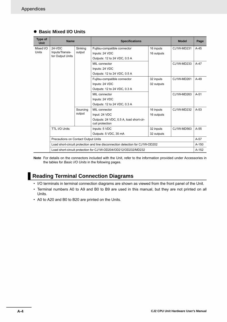
Appendices
A-4 CJ2 CPU Unit Hardware User’s Manual
� Basic Mixed I/O Units
Note For details on the connectors included with the Unit, refer to the information provided under Accessories inthe tables for Basic I/O Units in the following pages.
• I/O terminals in terminal connection diagrams are shown as viewed from the front panel of the Unit.• Terminal numbers A0 to A9 and B0 to B9 are used in this manual, but they are not printed on all
Units. • A0 to A20 and B0 to B20 are printed on the Units.
Type of Unit Name Specifications Model Page
Mixed I/O Units
24-VDC Inputs/Transis-tor Output Units
Sinking output
Fujitsu-compatible connectorInputs: 24 VDCOutputs: 12 to 24 VDC, 0.5 A
16 inputs16 outputs
CJ1W-MD231 A-45
MIL connector Inputs: 24 VDCOutputs: 12 to 24 VDC, 0.5 A
CJ1W-MD233 A-47
Fujitsu-compatible connectorInputs: 24 VDCOutputs: 12 to 24 VDC, 0.3 A
32 inputs32 outputs
CJ1W-MD261 A-49
MIL connectorInputs: 24 VDCOutputs: 12 to 24 VDC, 0.3 A
CJ1W-MD263 A-51
Sourcingoutput
MIL connector Input: 24 VDCOutputs: 24 VDC, 0.5 A, load short-cir-cuit protection
16 inputs16 outputs
CJ1W-MD232 A-53
TTL I/O Units Inputs: 5 VDCOutputs: 5 VDC, 35 mA
32 inputs32 outputs
CJ1W-MD563 A-55
Precautions on Contact Output Units A-57
Load short-circuit protection and line disconnection detection for CJ1W-OD202 A-150
Load short-circuit protection for CJ1W-OD204/OD212/OD232/MD232 A-152
Reading Terminal Connection Diagrams
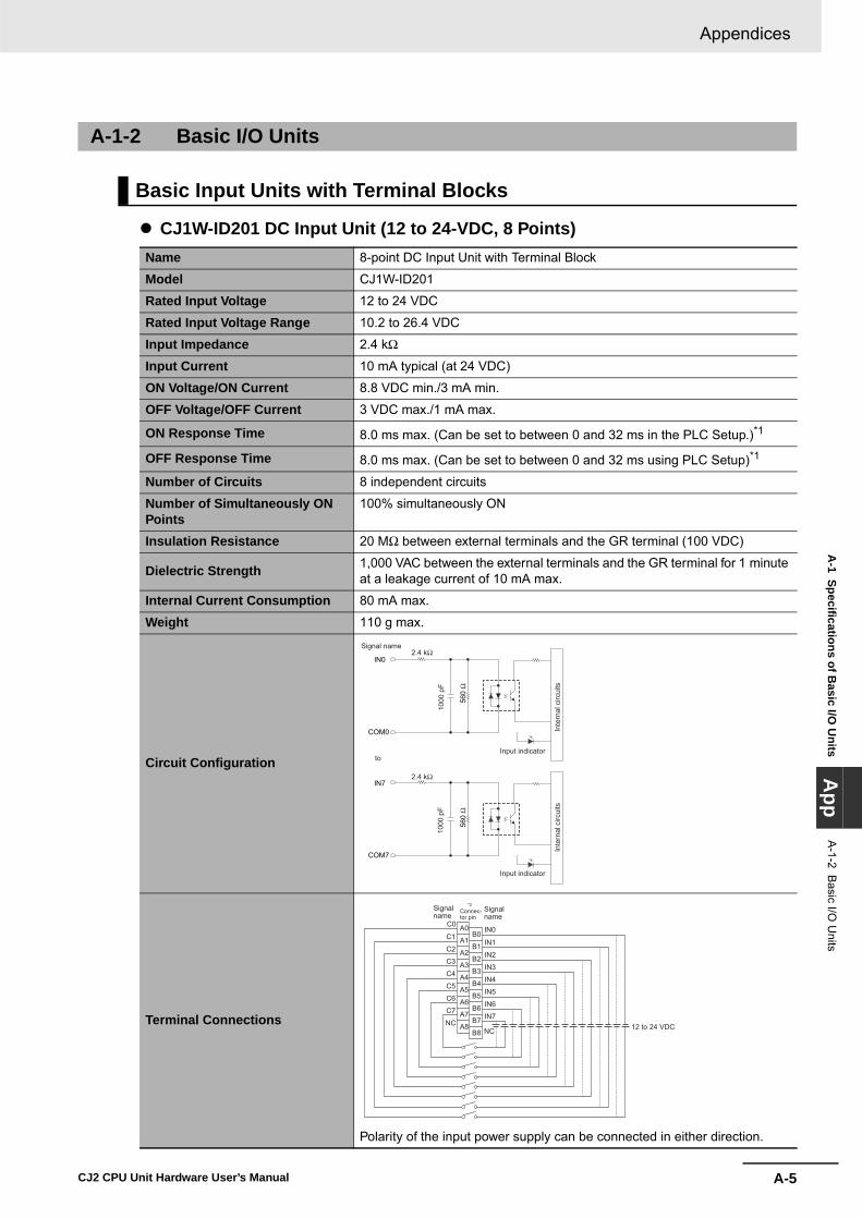
A-5
Appendices
CJ2 CPU Unit Hardware User’s Manual
A-1 Specifications of B
asic I/O U
nitsA
ppA
-1-2 Basic I/O
Units
� CJ1W-ID201 DC Input Unit (12 to 24-VDC, 8 Points)
A-1-2 Basic I/O Units
Basic Input Units with Terminal Blocks
Name 8-point DC Input Unit with Terminal Block
Model CJ1W-ID201
Rated Input Voltage 12 to 24 VDC
Rated Input Voltage Range 10.2 to 26.4 VDC
Input Impedance 2.4 kΩ
Input Current 10 mA typical (at 24 VDC)
ON Voltage/ON Current 8.8 VDC min./3 mA min.
OFF Voltage/OFF Current 3 VDC max./1 mA max.
ON Response Time 8.0 ms max. (Can be set to between 0 and 32 ms in the PLC Setup.)*1
OFF Response Time 8.0 ms max. (Can be set to between 0 and 32 ms using PLC Setup)*1
Number of Circuits 8 independent circuits
Number of Simultaneously ON Points
100% simultaneously ON
Insulation Resistance 20 MΩ between external terminals and the GR terminal (100 VDC)
Dielectric Strength 1,000 VAC between the external terminals and the GR terminal for 1 minute at a leakage current of 10 mA max.
Internal Current Consumption 80 mA max.
Weight 110 g max.
Circuit Configuration
Terminal Connections
Polarity of the input power supply can be connected in either direction.
COM7
IN7
COM0
IN0
560
Ω
2.4 kΩ
560
Ω
2.4 kΩ
1000
pF
Input indicator
Inte
rnal
circ
uits
to
1000
pF
Input indicator
Inte
rnal
circ
uits
Signal name
B1
IN0
B2
IN1
B3
IN2
B4
IN3
B5
IN4
B6
IN5
B7
IN6
B8
IN7
NC
C0
C1
C2
C3
C4
C5
C6
C7
NC
B0A1
A2
A3
A4
A5
A6
A7
A8
A0
Signalname
Signalname
Connec-tor pin
12 to 24 VDC
*2
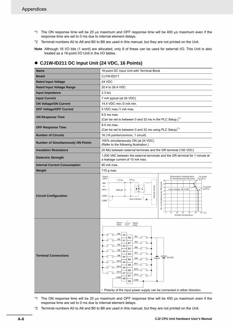
Appendices
A-6 CJ2 CPU Unit Hardware User’s Manual
*1 The ON response time will be 20 μs maximum and OFF response time will be 400 μs maximum even if theresponse time are set to 0 ms due to internal element delays.
*2 Terminal numbers A0 to A8 and B0 to B8 are used in this manual, but they are not printed on the Unit.
Note Although 16 I/O bits (1 word) are allocated, only 8 of these can be used for external I/O. This Unit is alsotreated as a 16-point I/O Unit in the I/O tables.
� CJ1W-ID211 DC Input Unit (24 VDC, 16 Points)
*1 The ON response time will be 20 μs maximum and OFF response time will be 400 μs maximum even if theresponse time are set to 0 ms due to internal element delays.
*2 Terminal numbers A0 to A8 and B0 to B8 are used in this manual, but they are not printed on the Unit.
Name 16-point DC Input Unit with Terminal Block
Model CJ1W-ID211
Rated Input Voltage 24 VDC
Rated Input Voltage Range 20.4 to 26.4 VDC
Input Impedance 3.3 kΩ
Input Current 7 mA typical (at 24 VDC)
ON Voltage/ON Current 14.4 VDC min./3 mA min.
OFF Voltage/OFF Current 5 VDC max./1 mA max.
ON Response Time8.0 ms max. (Can be set to between 0 and 32 ms in the PLC Setup.)*1
OFF Response Time8.0 ms max. (Can be set to between 0 and 32 ms using PLC Setup)*1
Number of Circuits 16 (16 points/common, 1 circuit)
Number of Simultaneously ON Points 100% simultaneously ON (at 24 VDC) (Refer to the following illustration.)
Insulation Resistance 20 MΩ between external terminals and the GR terminal (100 VDC)
Dielectric Strength 1,000 VAC between the external terminals and the GR terminal for 1 minute at a leakage current of 10 mA max.
Internal Current Consumption 80 mA max.
Weight 110 g max.
Circuit Configuration
Terminal Connections
• Polarity of the input power supply can be connected in either direction.
IN0
IN15
COM
COM
1000 pF
470 Ω3.3 kΩ
Inte
rnal
circ
uits
Input indicator
to
Signalname
18
16
14
12
10
8
6
4
2
00 10 20 30 40 50 60
No.
of s
imul
tane
ousl
y O
N p
oint
s
Input voltage: 26.4 VDC12 points at 55°C.
16 points at 45°C.
Ambient temperature(°C)
Temperature characteristics for simultaneously ON points
B1
IN1
B2
IN3
B3
IN5
B4
IN7
B5
IN9
B6
IN11
B7
IN13
B8
IN15
COM
24 VDC
A1
IN0
A2
IN2
A3
IN4
A4
IN6
A5
IN8
A6
IN10
A7
IN12
A8
IN14
COM
B0A0
Signalname
Signalname
Connec-tor pin
*2

A-7
Appendices
CJ2 CPU Unit Hardware User’s Manual
A-1 Specifications of B
asic I/O U
nitsA
ppA
-1-2 Basic I/O
Units
� CJ1W-ID212 DC Input Unit (24 VDC, 16 Points)
*1 The ON response time will be 15 μs maximum and OFF response time will be 90 μs maximum even if theresponse time are set to 0 ms due to internal element delays.
*2 Terminal numbers A0 to A8 and B0 to B8 are used in this manual, but they are not printed on the Unit.
Name 16-point DC Input Unit with Terminal Block
Model CJ1W-ID212
Rated Input Voltage 24 VDC
Rated Input Voltage Range 20.4 to 26.4 VDC
Input Impedance 3.3 kΩ
Input Current 7 mA typical (at 24 VDC)
ON Voltage/ON Current 14.4 VDC min./3 mA min.
OFF Voltage/OFF Current 5 VDC max./1 mA max.
ON Response Time8.0 ms max. (Can be set to between 0 and 32 ms in the PLC Setup.)*1
OFF Response Time8.0 ms max. (Can be set to between 0 and 32 ms using PLC Setup)*1
Number of Circuits 16 (16 points/common, 1 circuit)
Number of Simultaneously ON Points 100% simultaneously ON (at 24 VDC) (Refer to the following illustration.)
Insulation Resistance 20 MΩ between external terminals and the GR terminal (100 VDC)
Dielectric Strength 1,000 VAC between the external terminals and the GR terminal for 1 minute at a leakage current of 10 mA max.
Internal Current Consumption 130 mA max.
Weight 110 g max.
Circuit Configuration
Terminal Connections
• Polarity of the input power supply can be connected in either direction.
IN0
IN15
COM
COM
1000 pF
470 Ω3.3 kΩ
Inte
rnal
circ
uits
Input indicator
to
Signalname
18
16
14
12
10
8
6
4
2
00 10 20 30 40 50 60
No.
of s
imul
tane
ousl
y O
N p
oint
s
Input voltage: 26.4 VDC12 points at 55°C.
16 points at 45°C.
Ambient temperature(°C)
Temperature characteristics for simultaneously ON points
B1
IN1
B2
IN3
B3
IN5
B4
IN7
B5
IN9
B6
IN11
B7
IN13
B8
IN15
COM
24 VDC
A1
IN0
A2
IN2
A3
IN4
A4
IN6
A5
IN8
A6
IN10
A7
IN12
A8
IN14
COM
B0A0
Signalname
Signalname
Connec-tor pin
*2

Appendices
A-8 CJ2 CPU Unit Hardware User’s Manual
� CJ1W-ID231 DC Input Unit (24 VDC, 32 Points)Name 32-point DC Input Unit with Fujitsu Connector
Model CJ1W-ID231
Rated Input Voltage 24 VDC
Rated Input Voltage Range
20.4 to 26.4 VDC
Input Impedance 5.6 kΩ
Input Current 4.1 mA typical (at 24 VDC)
ON Voltage/ON Current 19.0 VDC min./3 mA min.
OFF Voltage/OFF Cur-rent
5 VDC max./1 mA max.
ON Response Time 8.0 ms max. (Can be set to between 0 and 32 in the PLC Setup.)*1
OFF Response Time 8.0 ms max. (Can be set to between 0 and 32 in the PLC Setup.)*1
Number of Circuits 32 (16 points/common, 2 circuits)
Number of Simulta-neously ON Points
75% (12 points/common) simultaneously ON (at 24 VDC) (Refer to the following illus-tration.)
Insulation Resistance 20 MΩ between external terminals and the GR terminal (100 VDC)
Dielectric Strength 1,000 VAC between the external terminals and the GR terminal for 1 minute at a leakage current of 10 mA max.
Internal Current Con-sumption
90 mA max.
Weight 70 g max.
Accessories None
Circuit Configuration
IN0
IN15
COM0
IN0
IN15
COM1
COM0
COM1
SW
560
Ω56
0Ω
5.6 kΩ
5.6 kΩ
1000
pF
1000
pF
Inte
rnal
circ
uits
Input indicator
to
toWdm+1
Wd m
AllocatedCIO word
Signalname
Connector row A
Connector row B
0
5
10
15
20
25
30
35
0 10 20 30 40 50 60
Number of Simultaneously ON Points vs. Ambient Temperature Characteristic
Num
ber o
f sim
ulta
neou
sly
ON
poi
nts
Ambient Temperature(°C)
10 points/commonat 55°C
12 points/commonat 55°C
Input voltage: 26.4 VDC
Input voltage: 24 VDC
32 points at 48°C32 points at 40°C
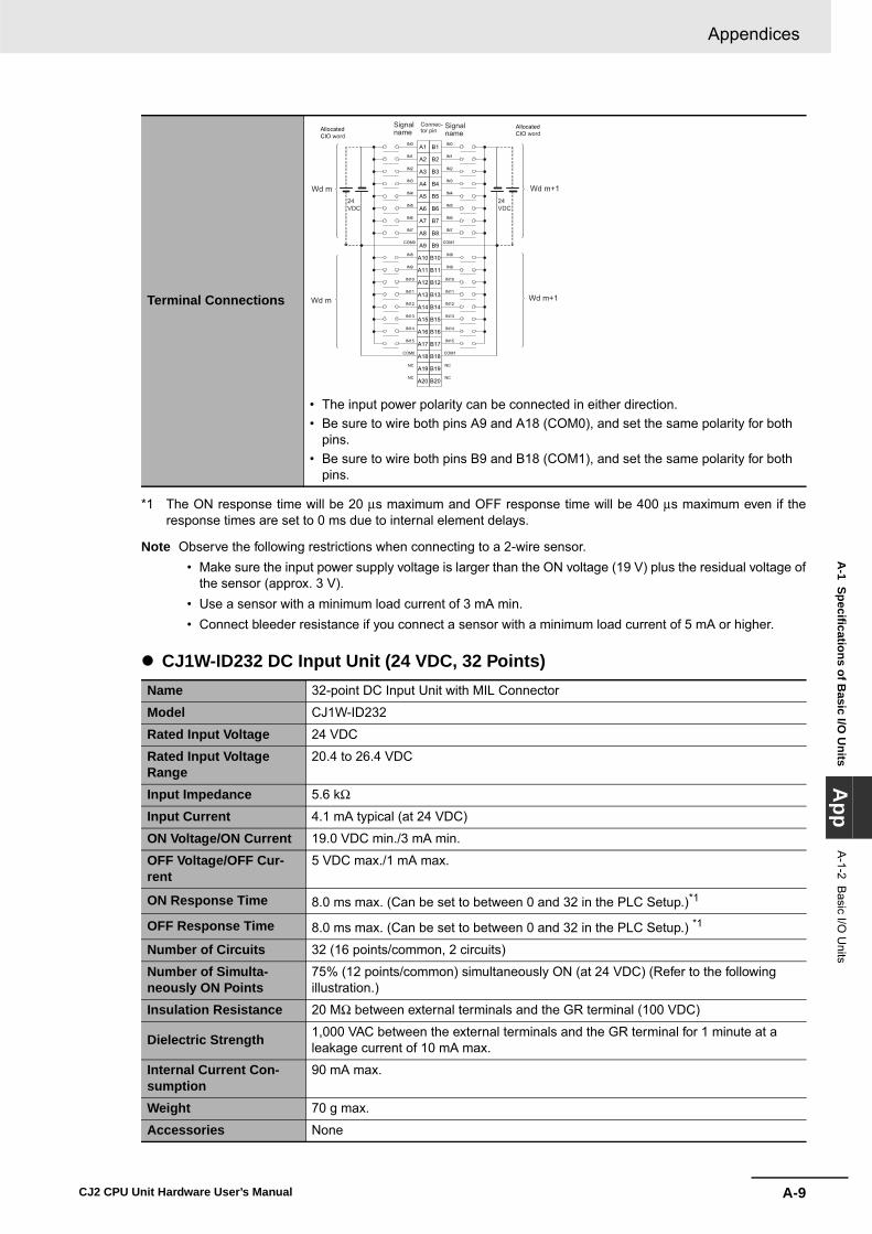
A-9
Appendices
CJ2 CPU Unit Hardware User’s Manual
A-1 Specifications of B
asic I/O U
nitsA
ppA
-1-2 Basic I/O
Units
*1 The ON response time will be 20 μs maximum and OFF response time will be 400 μs maximum even if theresponse times are set to 0 ms due to internal element delays.
Note Observe the following restrictions when connecting to a 2-wire sensor. • Make sure the input power supply voltage is larger than the ON voltage (19 V) plus the residual voltage of
the sensor (approx. 3 V). • Use a sensor with a minimum load current of 3 mA min. • Connect bleeder resistance if you connect a sensor with a minimum load current of 5 mA or higher.
� CJ1W-ID232 DC Input Unit (24 VDC, 32 Points)
Terminal Connections
• The input power polarity can be connected in either direction.• Be sure to wire both pins A9 and A18 (COM0), and set the same polarity for both
pins.• Be sure to wire both pins B9 and B18 (COM1), and set the same polarity for both
pins.
Name 32-point DC Input Unit with MIL Connector
Model CJ1W-ID232
Rated Input Voltage 24 VDC
Rated Input Voltage Range
20.4 to 26.4 VDC
Input Impedance 5.6 kΩ
Input Current 4.1 mA typical (at 24 VDC)
ON Voltage/ON Current 19.0 VDC min./3 mA min.
OFF Voltage/OFF Cur-rent
5 VDC max./1 mA max.
ON Response Time 8.0 ms max. (Can be set to between 0 and 32 in the PLC Setup.)*1
OFF Response Time 8.0 ms max. (Can be set to between 0 and 32 in the PLC Setup.) *1
Number of Circuits 32 (16 points/common, 2 circuits)
Number of Simulta-neously ON Points
75% (12 points/common) simultaneously ON (at 24 VDC) (Refer to the following illustration.)
Insulation Resistance 20 MΩ between external terminals and the GR terminal (100 VDC)
Dielectric Strength 1,000 VAC between the external terminals and the GR terminal for 1 minute at a leakage current of 10 mA max.
Internal Current Con-sumption
90 mA max.
Weight 70 g max.
Accessories None
IN0
IN1
IN2
IN3
IN4
IN5
IN6
IN7
IN0
IN1
IN2
IN3
IN4
IN5
IN6
IN7
COM0
IN8
IN9
IN10
IN11
IN12
IN13
IN14
IN15
IN8
IN9
IN10
IN11
IN12
IN13
IN14
IN15
COM0
NC
NC
COM1
COM1
NC
NC
AllocatedCIO word
AllocatedCIO word
A1
A2
A3
A4
A5
A6
A7
A8
A9
A10
A11
A12
A13
A14
A15
A16
A17
A18
A19
A20
B1
B2
B3
B4
B5
B6
B7
B8
B9
B10
B11
B12
B13
B14
B15
B16
B17
B18
B19
B20
Wd m+1Wd m 24VDC
Wd m Wd m+1
24VDC
Signalname
Signalname
Connec-tor pin

Appendices
A-10 CJ2 CPU Unit Hardware User’s Manual
*1 The ON response time will be 20 μs maximum and OFF response time will be 400 μs maximum even if theresponse times are set to 0 ms due to internal element delays.
Note Observe the following restrictions when connecting to a 2-wire sensor. • Make sure the input power supply voltage is larger than the ON voltage (19 V) plus the residual voltage of
the sensor (approx. 3 V). • Use a sensor with a minimum load current of 3 mA min. • Connect bleeder resistance if you connect a sensor with a minimum load current of 5 mA or higher.
� CJ1W-ID233 DC Input Unit (24 VDC, 32 Points)
Circuit Configuration
Terminal Connections
• The input power polarity can be connected in either direction.• Be sure to wire both pins 23 and 24 (COM0), and set the same polarity for both
pins.• Be sure to wire both pins 3 and 4 (COM1), and set the same polarity for both pins.
Name 32-point DC Input Unit with MIL Connector
Model CJ1W-ID233
Rated Input Voltage 24 VDC
Rated Input Voltage Range
20.4 to 26.4 VDC
Input Impedance 5.6 kΩ
Input Current 4.1 mA typical (at 24 VDC)
ON Voltage/ON Current 19.0 VDC min./3 mA min.
OFF Voltage/OFF Cur-rent
5 VDC max./1 mA max.
IN0
IN15
COM0
IN0
IN15
COM1
COM0
COM1
SW
560
Ω56
0Ω
5.6 kΩ
5.6 kΩ
1000
pF
1000
pF
Inte
rnal
circ
uits
Input indicator
to
toWdm+1
Wd m
AllocatedCIO word
Signalname
Connector row A
Connector row B
0
5
10
15
20
25
30
35
0 10 20 30 40 50 60Num
ber o
f sim
ulta
neou
sly
ON
poi
nts
Ambient Temperature(°C)
10 points/common at 55°C
12 points/common at 55°C
Input voltage: 26.4 VDC
Input voltage: 24 VDC
32 points at 48°C32 points at 40°C
Number of Simultaneously ON Points vs. Ambient Temperature Characteristic
2 NC
4 COM1
6 IN7
8 IN6
10 IN5
12 IN4
14 IN3
16 IN2
18 IN1
20 IN0
IN7
IN6
IN5
IN4
IN3
IN2
IN1
IN0
22 NC
24262830323436
1NC
3COM1
5IN15
7IN14
9IN13
11IN12
13IN11
15IN10
17IN9
19IN8
21NC
23252729313335
3840
3739
COM0 COM0
IN15
IN14
IN13
IN12
IN11
IN10
IN9
IN8
Wd m+1 Wd m+1
Wd m Wd m
24 VDC
24 VDC
Signalname
Signalname
Connec-tor pinAllocated
CIO wordAllocatedCIO word

A-11
Appendices
CJ2 CPU Unit Hardware User’s Manual
A-1 Specifications of B
asic I/O U
nitsA
ppA
-1-2 Basic I/O
Units
*1 The ON response time will be 15 μs maximum and OFF response time will be 90 μs maximum even if theresponse times are set to 0 ms due to internal element delays.
Note Observe the following restrictions when connecting to a 2-wire sensor. • Make sure the input power supply voltage is larger than the ON voltage (19 V) plus the residual voltage of
the sensor (approx. 3 V). • Use a sensor with a minimum load current of 3 mA min. • Connect bleeder resistance if you connect a sensor with a minimum load current of 5 mA or higher.
ON Response Time 8.0 ms max. (Can be set to between 0 and 32 in the PLC Setup.)*1
OFF Response Time 8.0 ms max. (Can be set to between 0 and 32 in the PLC Setup.) *1
Number of Circuits 32 (16 points/common, 2 circuits)
Number of Simulta-neously ON Points
75% (12 points/common) simultaneously ON (at 24 VDC) (Refer to the following illustration.)
Insulation Resistance 20 MΩ between external terminals and the GR terminal (100 VDC)
Dielectric Strength 1,000 VAC between the external terminals and the GR terminal for 1 minute at a leakage current of 10 mA max.
Internal Current Con-sumption
200 mA max.
Weight 70 g max.
Accessories None
Circuit Configuration
Terminal Connections
• The input power polarity can be connected in either direction.• Be sure to wire both pins 23 and 24 (COM0), and set the same polarity for both
pins.• Be sure to wire both pins 3 and 4 (COM1), and set the same polarity for both pins.
IN0
IN15
COM0
IN0
IN15
COM1
COM0
COM1
SW56
0Ω
560
Ω
5.6 kΩ
5.6 kΩ
1000
pF
1000
pF
Inte
rnal
circ
uits
Input indicator
to
toWdm+1
Wd m
AllocatedCIO word
Signalname
Connector row A
Connector row B
0
5
10
15
20
25
30
35
0 10 20 30 40 50 60Num
ber o
f sim
ulta
neou
sly
ON
poi
nts
Ambient Temperature(°C)
10 points/common at 55°C
12 points/common at 55°C
Input voltage: 26.4 VDC
Input voltage: 24 VDC
32 points at 48°C32 points at 40°C
Number of Simultaneously ON Points vs. Ambient Temperature Characteristic
2 NC
4 COM1
6 IN7
8 IN6
10 IN5
12 IN4
14 IN3
16 IN2
18 IN1
20 IN0
IN7
IN6
IN5
IN4
IN3
IN2
IN1
IN0
22 NC
24262830323436
1NC
3COM1
5IN15
7IN14
9IN13
11IN12
13IN11
15IN10
17IN9
19IN8
21NC
23252729313335
3840
3739
COM0 COM0
IN15
IN14
IN13
IN12
IN11
IN10
IN9
IN8
Wd m+1 Wd m+1
Wd m Wd m
24 VDC
24 VDC
Signalname
Signalname
Connec-tor pinAllocated
CIO wordAllocatedCIO word
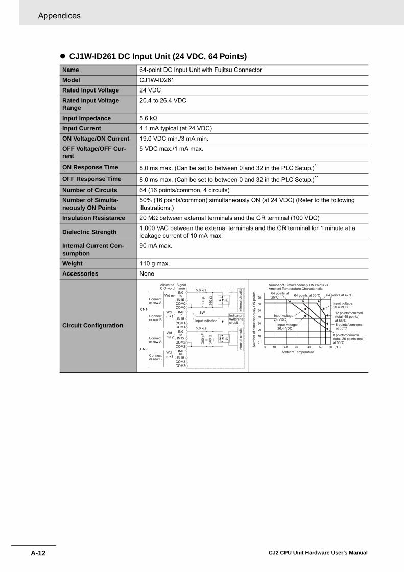
Appendices
A-12 CJ2 CPU Unit Hardware User’s Manual
� CJ1W-ID261 DC Input Unit (24 VDC, 64 Points)Name 64-point DC Input Unit with Fujitsu Connector
Model CJ1W-ID261
Rated Input Voltage 24 VDC
Rated Input Voltage Range
20.4 to 26.4 VDC
Input Impedance 5.6 kΩ
Input Current 4.1 mA typical (at 24 VDC)
ON Voltage/ON Current 19.0 VDC min./3 mA min.
OFF Voltage/OFF Cur-rent
5 VDC max./1 mA max.
ON Response Time 8.0 ms max. (Can be set to between 0 and 32 in the PLC Setup.)*1
OFF Response Time 8.0 ms max. (Can be set to between 0 and 32 in the PLC Setup.)*1
Number of Circuits 64 (16 points/common, 4 circuits)
Number of Simulta-neously ON Points
50% (16 points/common) simultaneously ON (at 24 VDC) (Refer to the following illustrations.)
Insulation Resistance 20 MΩ between external terminals and the GR terminal (100 VDC)
Dielectric Strength 1,000 VAC between the external terminals and the GR terminal for 1 minute at a leakage current of 10 mA max.
Internal Current Con-sumption
90 mA max.
Weight 110 g max.
Accessories None
Circuit Configuration
SWCN1
IN0
IN15COM0
IN0
IN15
COM0
COM1COM1
IN0
IN15COM2
IN0
IN15
COM2
COM3COM3
CN2
5.6 kΩ
1000
pF
560
Ω
5.6 kΩ
Input indicatorIndicatorswitching circuit
Inte
rnal
circ
uits
Inte
rnal
circ
uits
1000
pF
560
Ω
Wdm+1
Wd m
Wdm+2
Wdm+3
to
to
to
to
AllocatedCIO word
Signalname
Connector row A
Connector row B
Connector row A
Connector row B
0
10
20
30
40
50
60
70
0 10 20 30 40 50 60
Ambient Temperature
8 points/common (total: 26 points max.) at 55°C
8 points/common at 55°C
12 points/common (total: 45 points) at 55°C
Input voltage: 20.4 VDC
Input voltage: 26.4 VDC
Input voltage: 24 VDC
Num
ber o
f sim
ulta
neou
sly
ON
poi
nts
Number of Simultaneously ON Points vs. Ambient Temperature Characteristic
64 points at 25°C 64 points at 47°C
(°C)
64 points at 35°C
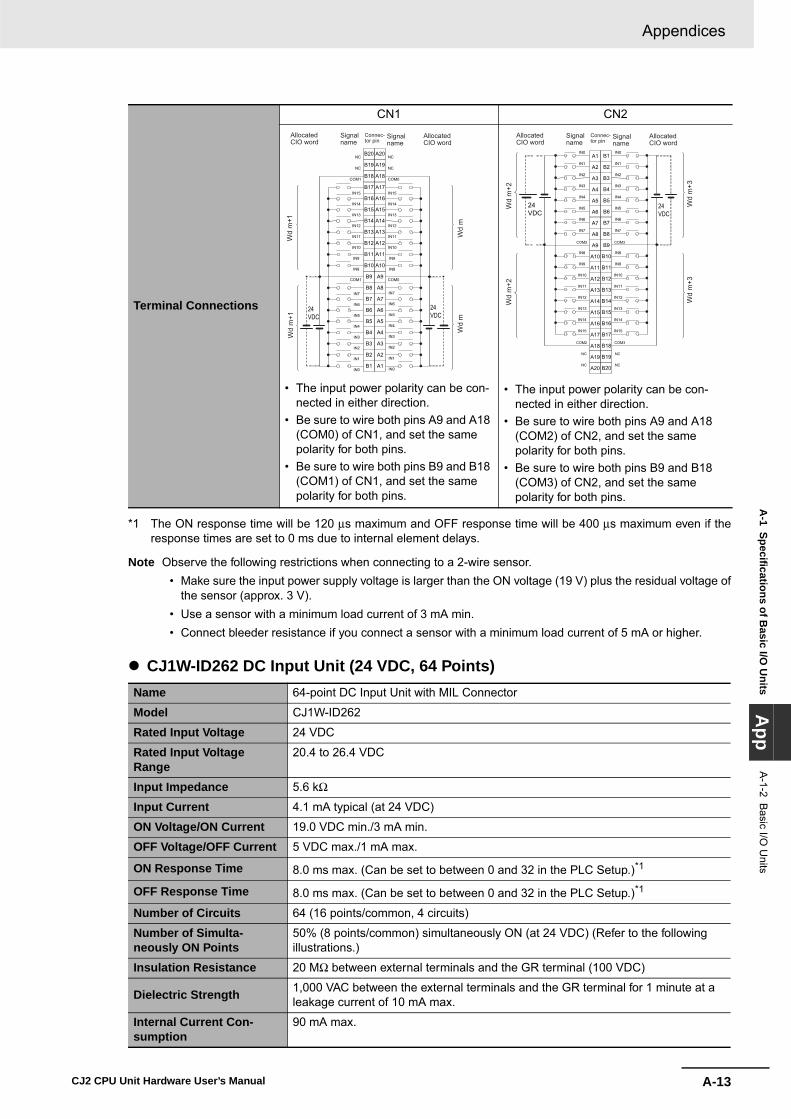
A-13
Appendices
CJ2 CPU Unit Hardware User’s Manual
A-1 Specifications of B
asic I/O U
nitsA
ppA
-1-2 Basic I/O
Units
*1 The ON response time will be 120 μs maximum and OFF response time will be 400 μs maximum even if theresponse times are set to 0 ms due to internal element delays.
Note Observe the following restrictions when connecting to a 2-wire sensor. • Make sure the input power supply voltage is larger than the ON voltage (19 V) plus the residual voltage of
the sensor (approx. 3 V). • Use a sensor with a minimum load current of 3 mA min. • Connect bleeder resistance if you connect a sensor with a minimum load current of 5 mA or higher.
� CJ1W-ID262 DC Input Unit (24 VDC, 64 Points)
Terminal Connections
CN1 CN2
• The input power polarity can be con-nected in either direction.
• Be sure to wire both pins A9 and A18 (COM0) of CN1, and set the same polarity for both pins.
• Be sure to wire both pins B9 and B18 (COM1) of CN1, and set the same polarity for both pins.
• The input power polarity can be con-nected in either direction.
• Be sure to wire both pins A9 and A18 (COM2) of CN2, and set the same polarity for both pins.
• Be sure to wire both pins B9 and B18 (COM3) of CN2, and set the same polarity for both pins.
Name 64-point DC Input Unit with MIL Connector
Model CJ1W-ID262
Rated Input Voltage 24 VDC
Rated Input Voltage Range
20.4 to 26.4 VDC
Input Impedance 5.6 kΩ
Input Current 4.1 mA typical (at 24 VDC)
ON Voltage/ON Current 19.0 VDC min./3 mA min.
OFF Voltage/OFF Current 5 VDC max./1 mA max.
ON Response Time 8.0 ms max. (Can be set to between 0 and 32 in the PLC Setup.)*1
OFF Response Time 8.0 ms max. (Can be set to between 0 and 32 in the PLC Setup.)*1
Number of Circuits 64 (16 points/common, 4 circuits)
Number of Simulta-neously ON Points
50% (8 points/common) simultaneously ON (at 24 VDC) (Refer to the following illustrations.)
Insulation Resistance 20 MΩ between external terminals and the GR terminal (100 VDC)
Dielectric Strength 1,000 VAC between the external terminals and the GR terminal for 1 minute at a leakage current of 10 mA max.
Internal Current Con-sumption
90 mA max.
COM0
COM0
NC
NC
COM1
COM1
NC
NC
24VDC
IN7
IN6
IN5
IN4
IN3
IN2
IN1
IN0
IN7
IN6
IN5
IN4
IN3
IN2
IN1
IN0
IN15
IN14
IN13
IN12
IN11
IN10
IN9
IN8
IN15
IN14
IN13
IN12
IN11
IN10
IN9
IN8
A20
A19
A18
A17
A16
A15
A14
A13
A12
A11
A10
A9
A8
A7
A6
A5
A4
A3
A2
A1
B20
B19
B18
B17
B16
B15
B14
B13
B12
B11
B10
B9
B8
B7
B6
B5
B4
B3
B2
B1
Wd
m+1
Wd
m
Wd
m 24
VDC
Wd
m+1
Signalname
Signalname
Connec-tor pin
AllocatedCIO word
AllocatedCIO word
COM3
COM3
NC
NC
COM2
COM2
NC
NC
IN8
IN9
IN10
IN11
IN12
IN13
IN14
IN15
IN8
IN9
IN10
IN11
IN12
IN13
IN14
IN15
IN0
IN1
IN2
IN3
IN4
IN5
IN6
IN7
IN0
IN1
IN2
IN3
IN4
IN5
IN6
IN7
B1
B2
B3
B4
B5
B6
B7
B8
B9
B10
B11
B12
B13
B14
B15
B16
B17
B18
B19
B20
A1
A2
A3
A4
A5
A6
A7
A8
A9
A10
A11
A12
A13
A14
A15
A16
A17
A18
A19
A20
Wd
m+2
24VDC
Wd
m+2
24VDC
Wd
m+3
Wd
m+3
Signalname
Signalname
Connec-tor pin
AllocatedCIO word
AllocatedCIO word

Appendices
A-14 CJ2 CPU Unit Hardware User’s Manual
*1 The ON response time will be 120 μs maximum and OFF response time will be 400 μs maximum even if theresponse times are set to 0 ms due to internal element delays.
Note Observe the following restrictions when connecting to a 2-wire sensor. • Make sure the input power supply voltage is larger than the ON voltage (19 V) plus the residual voltage of
the sensor (approx. 3 V). • Use a sensor with a minimum load current of 3 mA min. • Connect bleeder resistance if you connect a sensor with a minimum load current of 5 mA or higher.
� CJ1W-IA201 AC Input Unit (200 VAC, 8 Points)
Weight 110 g max.
Accessories None
Circuit Configuration
Terminal Connections
CN1 CN2
• The input power polarity can be connected in either direction.
• Be sure to wire both pins 23 and 24 (COM0) of CN1, and set the same polarity for both pins.
• Be sure to wire both pins 3 and 4 (COM1) of CN1, and set the same polarity for both pins.
• The input power polarity can be con-nected in either direction.
• Be sure to wire both pins 23 and 24 (COM2) of CN2, and set the same polar-ity for both pins.
• Be sure to wire both pins 3 and 4 (COM3) of CN2, and set the same polarity for both pins.
Name 8-point AC Input Unit with Terminal Block
Model CJ1W-IA201
Rated Input Voltage 200 to 240 VAC 50/60 Hz
Rated Input Voltage Range 170 to 264 VAC
Input Impedance 21 kΩ (50 Hz), 18 kΩ (60 Hz)
IN0
IN15 COM0
SWIN0
IN15
CN1COM0
COM1 COM1
IN0
IN15 COM2
IN0
IN15
COM2
COM3COM3
560
Ω56
0Ω
1000
pF
1000
pF
5.6 kΩ
5.6 kΩ
CN2
to
to
to
to
Input indicatorIndicatorswitching circuit
Inte
rnal
circ
uits
Inte
rnal
circ
uits
Wd m+1
Wd m
Wd m+2
Wd m+3
AllocatedCIO word
Signalname
0
10
20
30
40
50
60
70
0 10 20 30 40 50 60
Ambient Temperature
8 points/common (total: 26 points max.) at 55°C
8 points/common at 55°C
12 points/common (total: 45 points) at 55°C
Input voltage: 20.4 VDC
Input voltage: 26.4 VDC
Input voltage: 24 VDC
Num
ber o
f sim
ulta
neou
sly
ON
poi
nts
Number of Simultaneously ON Points vs. Ambient Temperature Characteristic
64 points at 47°C64 points at 35°C64 points at 25°C
(°C)
1 NC3
5
7
9
11
13
15
17
19
21
23
25
27
29
31
33
35
37
NC
39
2
4NC
6
8
10
12
14
16
18
COM1
20
22
24
26
28
30
32
34
36
38
40
COM1
NC
COM0 COM0
IN0
IN1
IN2
IN3
IN4
IN5
IN6
IN7
IN0
IN1
IN2
IN3
IN4
IN5
IN6
IN7
IN8
IN9
IN10
IN11
IN12
IN13
IN14
IN15
IN8
IN9
IN10
IN11
IN12
IN13
IN14
IN15
24 VDC
24 VDC
Wd
m+1
Wd
m+1
Wd
m
Wd
m
Signalname
Signalname
Connec-tor pin
AllocatedCIO word
AllocatedCIO word
40
38
36
34
32
30
28
26
24
22
20
18
16
14
12
10
8
6
4
NC2COM3
39
37
35
33
31
29
27
25
23COM221
19
17
15
13
11
9
7
5
3
NC 1COM3
COM2
NC NC
IN15
IN14
IN13
IN12
IN11
IN10
IN9
IN8
IN15
IN14
IN13
IN12
IN11
IN10
IN9
IN8
IN7
IN6
IN5
IN4
IN3
IN2
IN1
IN0
IN7
IN6
IN5
IN4
IN3
IN2
IN1
IN0
Wd
m+3
Wd
m+3
Wd
m+2
Wd
m+2
24 VDC
24VDC
Signalname
Signalname
Connec-tor pin
AllocatedCIO word
AllocatedCIO word

A-15
Appendices
CJ2 CPU Unit Hardware User’s Manual
A-1 Specifications of B
asic I/O U
nitsA
ppA
-1-2 Basic I/O
Units
*1 The Input ON and OFF response times for Basic I/O Units can be set to 0 ms, 0.5 ms, 1 ms, 2 ms, 4 ms, 8 ms,16 ms, or 32 ms in the PLC Setup. When the response times have been set to 0 ms, the ON response time willbe 10 ms maximum and the OFF response time will be 40 ms maximum due to internal element delays.
*2 Terminal numbers A0 to A8 and B0 to B8 are used in this manual, but they are not printed on the Unit.
Note Although 16 I/O bits (1 word) are allocated, only 8 of these can be used for external I/O. This Unit is alsotreated as a 16-point I/O Unit in the I/O tables.
Input Current9 mA typical (at 200 VAC, 50 Hz), 11 mA typical (at 200 VAC, 60 Hz)
ON Voltage/ON Current 120 VAC min./4 mA min.
OFF Voltage/OFF Current 40 VAC max./2 mA max.
ON Response Time 18.0 ms max. (PLC Setup default setting: 8 ms)*1
OFF Response Time 48.0 ms max. (PLC Setup default setting: 8 ms)*1
Number of Circuits 8 (8 points/common, 1 circuit)
Number of Simultaneously ON Points 100% (8 points/common) simultaneously ON
Insulation Resistance 20 MΩ between external terminals and the GR terminal (500 VDC)
Dielectric Strength 2,000 VAC between the external terminals and the GR terminal for 1 minute at a leakage current of 10 mA max.
Internal Current Consumption 80 mA max.
Weight 130 g max.
Accessories None
Circuit Configuration
Terminal Connections
COM
IN0
IN7
820 Ω 1 MΩ
0.15 μF 220 Ω
Input indicator
Inte
rnal
circ
uits
to
Signalname
IN0
IN1
IN2
IN3
IN5
IN6
IN7
B0
B1
B2
B3
B4
B5
B6
B7
B8
IN4
A0
A1
A2
A3
A4
A5
A6
A7
A8 COM
NC
NC
NC
NC
NC
NC
NC
NC
NC
200 to 240 VAC
Signalname
Connec-tor pin
*2

Appendices
A-16 CJ2 CPU Unit Hardware User’s Manual
� CJ1W-IA111 AC Input Unit (100 VAC, 16 points)
*1 The Input ON and OFF response times for Basic I/O Units can be set to 0 ms, 0.5 ms, 1 ms, 2 ms, 4 ms, 8 ms,16 ms, or 32 ms in the PLC Setup. When the response times have been set to 0 ms, the ON response time willbe 10 ms maximum and the OFF response time will be 40 ms maximum due to internal element delays.
*2 Use an input voltage of 90 VAC or higher when connecting 2-wire sensors.*3 Terminal numbers A0 to A8 and B0 to B8 are used in this manual, but they are not printed on the Unit.
Name 16-point AC Input Unit with Terminal Block
Model CJ1W-IA111
Rated input voltage 100 to 120 VAC 50/60 Hz*2
Rated Input Voltage Range 85 to 132 VAC
Input Impedance 14.5 kΩ (50 Hz), 12 kΩ (60 Hz)
Input Current7 mA typical (at 100 VAC, 50 Hz), 8 mA typical (at 100 VAC, 60 Hz)
ON Voltage/ON Current 70 VAC min./4 mA min
OFF Voltage/OFF Current 20 VAC max./2 mA max
ON Response Time 18 ms max. (PLC Setup default setting: 8 ms)*1
OFF Response Time 48 ms max. (PLC Setup default setting: 8 ms)*1
Number of Circuits 16 (16 points/common, 1 circuit)
Number of Inputs ON Simultaneously 100% simultaneously ON (16 points/common)
Insulation Resistance 20 MΩ between external terminals and the GR terminal (500 VDC)
Dielectric Strength 2,000 VAC between the external terminals and the GR terminal for 1 minute at a leakage current of 10 mA max.
Internal Current Consumption 90 mA max.
Weight 130 g max.
Accessories None
Circuit Layout
Terminal Connections
COM
IN0
IN15
470 Ω 1 MΩ
0.22 μF270 Ω
Input indicator
Inte
rnal
circ
uits
to
Signalname
A0
A1
A2
A3
A4
A5
A6
A7
A8
B0
B1
B2
B3
B4
B5
B6
B7
B8
COMCOM
IN0
IN2
IN4
IN6
IN8
IN10
IN12
IN14
IN1
IN3
IN5
IN7
IN9
IN11
IN13
IN15
100 to 120 VAC
Signalname
Signalname
Connec-tor pin
*3

A-17
Appendices
CJ2 CPU Unit Hardware User’s Manual
A-1 Specifications of B
asic I/O U
nitsA
ppA
-1-2 Basic I/O
Units
� CJ1W-INT01 Interrupt Input Unit (16 Points)Name 16-point Interrupt Input Unit with Terminal Block
Model CJ1W-INT01
Rated Input Voltage 24 VDC
Rated Input Voltage Range
20.4 to 26.4 VDC
Input Impedance 3.3 kΩ
Input Current 7 mA typical (at 24 VDC)
ON Voltage/ON Current 14.4 VDC min./3 mA min.
OFF Voltage/OFF Current 5 VDC max./1 mA max.
ON Response Time 0.05 ms max.
OFF Response Time 0.5 ms max.
Number of Circuits 16 (16 points/common, 1 circuit)
Number of Simulta-neously ON Points
100% (16 points/common) simultaneously ON (24 VDC)
Insulation Resistance 20 MΩ between external terminals and GR terminal (at 100 VDC)
Dielectric Strength 1,000 VAC between external terminals and GR terminal for 1 minute at a leakage current of 10 mA max.
Internal Current Con-sumption
80 mA max.
Weight 110 g max.
Accessories None
Circuit Configuration
• Up to two Interrupt Input Units can be mounted to the CPU Rack, but they must be connected as one the five Unit*1 immediately next to the CPU Unit. If an Interrupt Input Unit is con-nected in any other position, an I/O setting error will occur.
• Set the pulse width of signals input to the Interrupt Input Unit so they satisfy the following conditions.
*1 With the CJ2JH-CPU6@-EIP CPUUnits, the Unit must be mounted asone of the four Units immediatelynext to the CPU Unit.
IN0
IN15
COM
COM
Inte
rnal
circ
uits
3.3 kΩ
1000
pF
470
Ω
to
Input indicator
Signalname
18
16
14
12
10
8
6
4
2
00 10 20 30 40 50 60
Ambient Temperature
12 points at 55°C
Num
ber o
f sim
ulta
neou
sly
ON
poi
nts
(°C)
16 points at 45°C
Input voltage: 26.4 VDC
Temperature characteristics for simultaneously ON points
ON
OFF 0.5 ms min.
0.05 ms min.
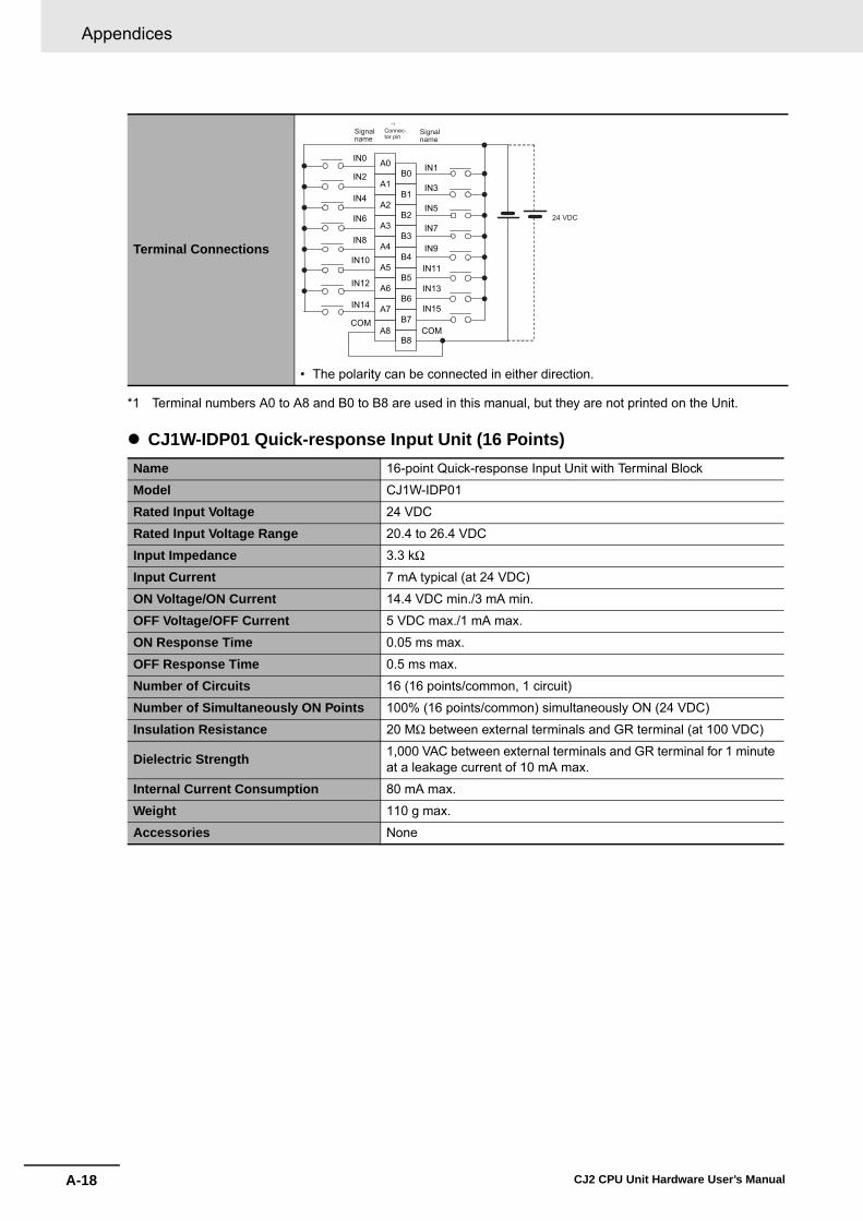
Appendices
A-18 CJ2 CPU Unit Hardware User’s Manual
*1 Terminal numbers A0 to A8 and B0 to B8 are used in this manual, but they are not printed on the Unit.
� CJ1W-IDP01 Quick-response Input Unit (16 Points)
Terminal Connections
• The polarity can be connected in either direction.
Name 16-point Quick-response Input Unit with Terminal Block
Model CJ1W-IDP01
Rated Input Voltage 24 VDC
Rated Input Voltage Range 20.4 to 26.4 VDC
Input Impedance 3.3 kΩ
Input Current 7 mA typical (at 24 VDC)
ON Voltage/ON Current 14.4 VDC min./3 mA min.
OFF Voltage/OFF Current 5 VDC max./1 mA max.
ON Response Time 0.05 ms max.
OFF Response Time 0.5 ms max.
Number of Circuits 16 (16 points/common, 1 circuit)
Number of Simultaneously ON Points 100% (16 points/common) simultaneously ON (24 VDC)
Insulation Resistance 20 MΩ between external terminals and GR terminal (at 100 VDC)
Dielectric Strength 1,000 VAC between external terminals and GR terminal for 1 minute at a leakage current of 10 mA max.
Internal Current Consumption 80 mA max.
Weight 110 g max.
Accessories None
A0
A1
A2
A3
A4
A5
A6
A7
A8
B0
B1
B2
B3
B4
B5
B6
B7
B8
COMCOM
IN1
IN3
IN5
IN7
IN9
IN11
IN13
IN15
IN0
IN2
IN4
IN6
IN8
IN10
IN12
IN14
24 VDC
Signalname
Signalname
Connec-tor pin
*1

A-19
Appendices
CJ2 CPU Unit Hardware User’s Manual
A-1 Specifications of B
asic I/O U
nitsA
ppA
-1-2 Basic I/O
Units
• With quick-response inputs, pulse inputs shorter than the CPU Unit's cycle time can be read by theCPU Unit.
• The pulse width (ON time) that can be read by the Quick-response Input Unit is 0.05 ms.• Inputs read by the internal circuits are cleared when inputs are refreshed.*1 Terminal numbers A0 to A8 and B0 to B8 are used in this manual, but they are not printed on the Unit.
Circuit Configuration
Terminal Connections
• The input power supply polarity can be connected in either direc-tion.
18
16
14
12
10
8
6
4
2
00 10 20 30 40 50 60
Ambient Temperature
12 points at 55°C
Num
ber o
f sim
ulta
neou
sly
ON
poi
nts
(°C)
16 points at 45°C
Input voltage: 26.4 VDC
Number of simultaneously ON points -- Ambient temperature characteristics
IN0
IN15
COM
COM
3.3 kΩ
470
Ω
1000
pFto
Input indicator Inte
rnal
circ
uits
Signalname
A0
A1
A2
A3
A4
A5
A6
A7
A8
B0
B1
B2
B3
B4
B5
B6
B7
B8
IN0
IN2
IN4
IN6
IN10
IN12
IN14
IN8
IN1
IN3
IN5
IN7
COM
IN11
IN13
IN15
IN9
COM
24 VDC
Signalname
Signalname
Connec-tor pin
*1

Appendices
A-20 CJ2 CPU Unit Hardware User’s Manual
� CJ1W-OC201 Contact Output Unit (Independent Relays, 8 Points)
*1 Terminal numbers A0 to A8 and B0 to B8 are used in this manual, but they are not printed on the Unit.
Note Although 16 I/O bits (1 word) are allocated, only 8 of these can be used for external I/O. This Unit is alsotreated as a 16-point I/O Unit in the I/O tables.
Basic Output Units
Name 8-point Contact Output Unit with Terminal Block (Independent Relays)
Model CJ1W-OC201
Max. Switching Capacity 2 A 250 VAC (cosφ = 1), 2 A 250 VAC (cosφ = 0.4), 2 A 24 VDC (16 A/Unit)
Min. Switching Capacity 1 mA 5 VDC
Relays NY-24W-K-IE (Fujitsu Takamizawa Components, Ltd.), Cannot be replaced.
Service Life of Relay
Electrical: 150,000 operations (24 VDC, resistive load)/100,000 oper-ations (240 VAC, cosφ = 0.4, inductive load) Mechanical: 20,000,000 operationsService life will vary depending on the connected load. Refer to page A-57 for information on service life according to the load.
ON Response Time 15 ms max.
OFF Response Time 15 ms max.
Number of Circuits 8 independent contacts
Insulation Resistance 20 MΩ between external terminals and the GR terminal (500 VDC)
Dielectric Strength 2,000 VAC between the external terminals and the GR terminal for 1 minute at a leakage current of 10 mA max.
Internal Current Consumption 90 mA 5 VDC max. 48 mA 24 VDC max. (6 mA × No. of ON points)
Weight 140 g max.
Circuit Configuration
Terminal Connections
• The input power supply polarity can be connected in either direc-tion.
OUT
OUTc
Output indicator
Inte
rnal
circ
uits
Signalname
B1
OUTC0
B2
OUTC1
B3
OUTC2
B4
OUTC3
B5
OUTC4
B6
OUTC5
B7
OUTC6
B8
OUTC7
NC
A1
OUT0
A2
OUT1
A3
OUT2
A4
OUT3
A5
OUT4
A6
OUT5
A7
OUT6
A8
OUT7
NC
B0A0
L
L
L
L
L
L
L
L
2 A 250 VAC, 2 A 24 VDC max.
Signalname
Signalname
Connec-tor pin
*1
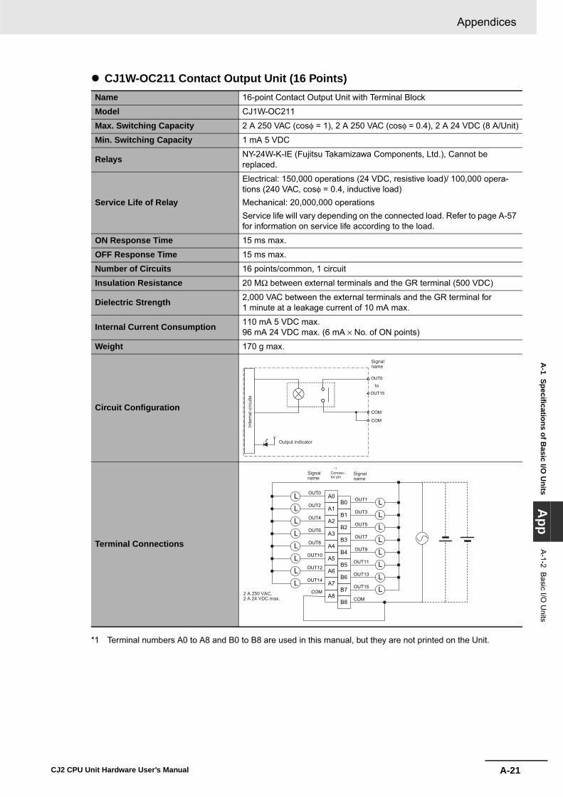
A-21
Appendices
CJ2 CPU Unit Hardware User’s Manual
A-1 Specifications of B
asic I/O U
nitsA
ppA
-1-2 Basic I/O
Units
� CJ1W-OC211 Contact Output Unit (16 Points)
*1 Terminal numbers A0 to A8 and B0 to B8 are used in this manual, but they are not printed on the Unit.
Name 16-point Contact Output Unit with Terminal Block
Model CJ1W-OC211
Max. Switching Capacity 2 A 250 VAC (cosφ = 1), 2 A 250 VAC (cosφ = 0.4), 2 A 24 VDC (8 A/Unit)
Min. Switching Capacity 1 mA 5 VDC
Relays NY-24W-K-IE (Fujitsu Takamizawa Components, Ltd.), Cannot be replaced.
Service Life of Relay
Electrical: 150,000 operations (24 VDC, resistive load)/ 100,000 opera-tions (240 VAC, cosφ = 0.4, inductive load) Mechanical: 20,000,000 operationsService life will vary depending on the connected load. Refer to page A-57 for information on service life according to the load.
ON Response Time 15 ms max.
OFF Response Time 15 ms max.
Number of Circuits 16 points/common, 1 circuit
Insulation Resistance 20 MΩ between external terminals and the GR terminal (500 VDC)
Dielectric Strength 2,000 VAC between the external terminals and the GR terminal for 1 minute at a leakage current of 10 mA max.
Internal Current Consumption 110 mA 5 VDC max. 96 mA 24 VDC max. (6 mA × No. of ON points)
Weight 170 g max.
Circuit Configuration
Terminal Connections
OUT15
OUT0
COM
COM
Output indicator
Inte
rnal
circ
uits
to
Signalname
B1
OUT1
B2
OUT3
B3
OUT5
B4
OUT7
B5
OUT9
B6
OUT11
B7
OUT13
B8
OUT15
A1
OUT0
A2
OUT2
A3
OUT4
A4
OUT6
A5
OUT8
A6
OUT10
A7
OUT12
A8
OUT14
COM
B0A0
COM
L
L
L
L
L
L
L
L
L
L
L
L
L
L
L
L2 A 250 VAC, 2 A 24 VDC max.
Signalname
Signalname
Connec-tor pin
*1

Appendices
A-22 CJ2 CPU Unit Hardware User’s Manual
� CJ1W-OA201 Triac Output Unit (8 Points)
*1 Terminal numbers A0 to A8 and B0 to B8 are used in this manual, but they are not printed on the Unit.
Note Although 16 I/O bits (1 word) are allocated, only 8 of these can be used for external I/O. This Unit is alsotreated as a 16-point I/O Unit in the I/O tables.
Name 8-point Triac Output Unit with Terminal Block
Model CJ1W-OA201
Max. Switching Capacity 0.6 A 250 VAC, 50/60 Hz (2.4 A/Unit)
Max. Inrush Current 15 A (pulse width: 10 ms max.)
Min. Switching Capacity 50 mA 75 VAC
Leakage Current 1.5 mA (200 VAC) max.
Residual Voltage 1.6 VAC max.
ON Response Time 1 ms max.
OFF Response Time 1/2 of load frequency + 1 ms or less.
Number of Circuits 8 (8 points/common, 1 circuit)
Surge Protector C.R Absorber + Surge Absorber
Fuses5 A (1/common, 1 used)The fuse cannot be replaced by the user.
Insulation Resistance 20 MΩ between the external terminals and the GR terminal (500 VDC)
Dielectric Strength 2,000 VAC between the external terminals and the GR terminal for 1 minute at a leakage current of 10 mA max.
Internal Current Consumption 220 mA max.
Weight 150 g max.
Circuit Configuration
Terminal Connections
COM
OUT0
OUT7
Output indicator
Inte
rnal
circ
uits
Fuse
to
Signalname
B0
B1
B2
B3
B4
B5
B6
B7
B8
A0
A1
A2
A3
A4
A5
A6
A7
A8 COM
NC
NC
NC
NC
NC
NC
NC
NC
NC
L
L
L
L
L
L
L
L
OUT0
OUT1
OUT2
OUT3
OUT4
OUT5
OUT6
OUT7
250 VAC max.
Signalname
Connec-tor pin
*1
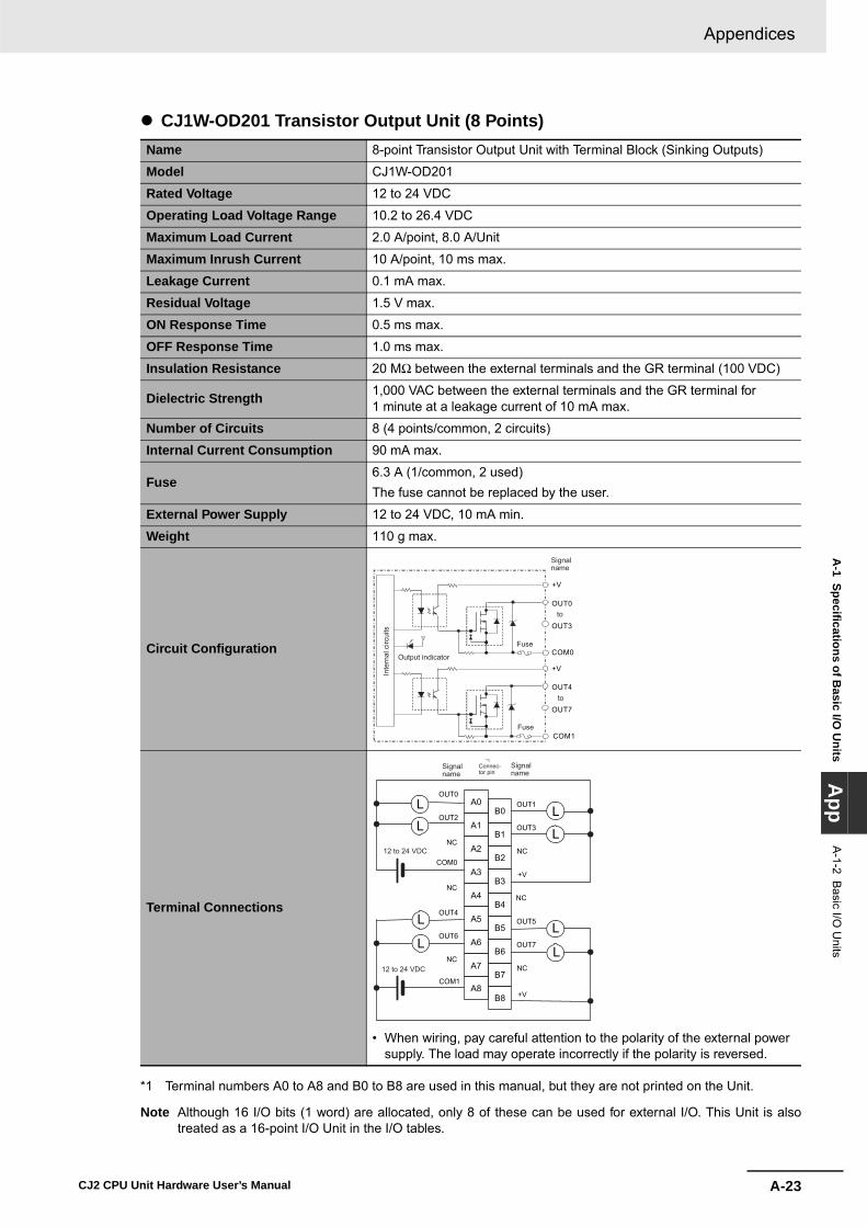
A-23
Appendices
CJ2 CPU Unit Hardware User’s Manual
A-1 Specifications of B
asic I/O U
nitsA
ppA
-1-2 Basic I/O
Units
� CJ1W-OD201 Transistor Output Unit (8 Points)
*1 Terminal numbers A0 to A8 and B0 to B8 are used in this manual, but they are not printed on the Unit.
Note Although 16 I/O bits (1 word) are allocated, only 8 of these can be used for external I/O. This Unit is alsotreated as a 16-point I/O Unit in the I/O tables.
Name 8-point Transistor Output Unit with Terminal Block (Sinking Outputs)
Model CJ1W-OD201
Rated Voltage 12 to 24 VDC
Operating Load Voltage Range 10.2 to 26.4 VDC
Maximum Load Current 2.0 A/point, 8.0 A/Unit
Maximum Inrush Current 10 A/point, 10 ms max.
Leakage Current 0.1 mA max.
Residual Voltage 1.5 V max.
ON Response Time 0.5 ms max.
OFF Response Time 1.0 ms max.
Insulation Resistance 20 MΩ between the external terminals and the GR terminal (100 VDC)
Dielectric Strength 1,000 VAC between the external terminals and the GR terminal for 1 minute at a leakage current of 10 mA max.
Number of Circuits 8 (4 points/common, 2 circuits)
Internal Current Consumption 90 mA max.
Fuse6.3 A (1/common, 2 used)The fuse cannot be replaced by the user.
External Power Supply 12 to 24 VDC, 10 mA min.
Weight 110 g max.
Circuit Configuration
Terminal Connections
• When wiring, pay careful attention to the polarity of the external power supply. The load may operate incorrectly if the polarity is reversed.
OUT0
+V
OUT3
COM0
OUT4
+V
OUT7
COM1
Inte
rnal
circ
uits
Output indicator
Fuse
Fuse
to
to
Signalname
OUT0
OUT2
COM0
NC
NC
OUT4
OUT6
B0
B1
B2
B3
B4
B5
B6
B7
B8
NC
A0 OUT1
OUT3
+V
NC
NC
NC
OUT5
OUT7
A1
A2
A3
A4
A5
A6
A7
A8COM1
+V
L
L
L
LL
L
L
L
12 to 24 VDC
12 to 24 VDC
Signalname
Signalname
Connec-tor pin
*1

Appendices
A-24 CJ2 CPU Unit Hardware User’s Manual
� CJ1W-OD203 Transistor Output Unit (8 Points)
*1 Terminal numbers A0 to A8 and B0 to B8 are used in this manual, but they are not printed on the Unit.
Note Although 16 I/O bits (1 word) are allocated, only 8 of these can be used for external I/O. This Unit is alsotreated as a 16-point I/O Unit in the I/O tables.
Name 8-point Transistor Output Unit with Terminal Block (Sinking Outputs)
Model CJ1W-OD203
Rated Voltage 12 to 24 VDC
Operating Load Voltage Range 10.2 to 26.4 VDC
Maximum Load Current 0.5 A/point, 4.0 A/Unit
Maximum Inrush Current 4.0 A/point, 10 ms max.
Leakage Current 0.1 mA max.
Residual Voltage 1.5 V max.
ON Response Time 0.1 ms max.
OFF Response Time 0.8 ms max.
Insulation Resistance 20 MΩ between the external terminals and the GR terminal (100 VDC)
Dielectric Strength 1,000 VAC between the external terminals and the GR terminal for 1 minute at a leakage current of 10 mA max.
Number of Circuits 8 (8 points/common, 1 circuit)
Internal Current Consumption 100 mA max.
Fuse None
External Power Supply 10.2 to 26.4 VDC, 20 mA min.
Weight 110 g max.
Circuit Configuration
Terminal Connections
• When wiring, pay careful attention to the polarity of the external power supply. The load may operate incorrectly if the polarity is reversed.
OUT0
OUT7
+V
COM
Output indicator
Inte
rnal
circ
uits
to
Signalname
B1
OUT1
B2
OUT3
B3
OUT5
B4
OUT7
B5
B6
B7
B8
A1
OUT0
A2
OUT2
A3
OUT4
A4
OUT6
A5
NC
A6
A7
A8COM
B0A0
+V
L
L
L
L
L
L
L
L
NC
NC
NC
NC
NC
NC
NC12 to 24 VDC
Signalname
Signalname
Connec-tor pin
*1
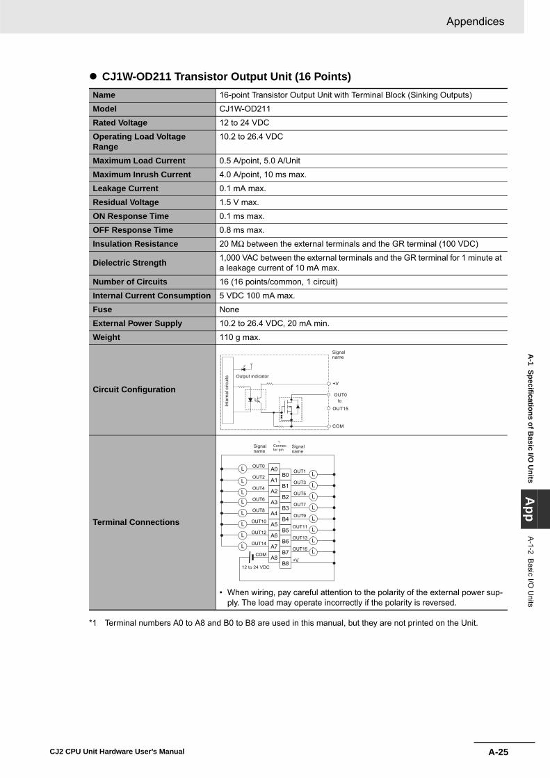
A-25
Appendices
CJ2 CPU Unit Hardware User’s Manual
A-1 Specifications of B
asic I/O U
nitsA
ppA
-1-2 Basic I/O
Units
� CJ1W-OD211 Transistor Output Unit (16 Points)
*1 Terminal numbers A0 to A8 and B0 to B8 are used in this manual, but they are not printed on the Unit.
Name 16-point Transistor Output Unit with Terminal Block (Sinking Outputs)
Model CJ1W-OD211
Rated Voltage 12 to 24 VDC
Operating Load Voltage Range
10.2 to 26.4 VDC
Maximum Load Current 0.5 A/point, 5.0 A/Unit
Maximum Inrush Current 4.0 A/point, 10 ms max.
Leakage Current 0.1 mA max.
Residual Voltage 1.5 V max.
ON Response Time 0.1 ms max.
OFF Response Time 0.8 ms max.
Insulation Resistance 20 MΩ between the external terminals and the GR terminal (100 VDC)
Dielectric Strength 1,000 VAC between the external terminals and the GR terminal for 1 minute at a leakage current of 10 mA max.
Number of Circuits 16 (16 points/common, 1 circuit)
Internal Current Consumption 5 VDC 100 mA max.
Fuse None
External Power Supply 10.2 to 26.4 VDC, 20 mA min.
Weight 110 g max.
Circuit Configuration
Terminal Connections
• When wiring, pay careful attention to the polarity of the external power sup-ply. The load may operate incorrectly if the polarity is reversed.
OUT0
+V
OUT15
COM
Output indicator
Inte
rnal
circ
uits
to
Signalname
B1
OUT1
B2
OUT3
B3
OUT5
B4
OUT7
B5
OUT9
B6
OUT11
B7
OUT13
B8
OUT15
A1
OUT0
A2
OUT2
A3
OUT4
A4
OUT6
A5
OUT8
A6
OUT10
A7
OUT12
A8
OUT14
COM
B0A0
+V
L
L
L
L
L
L
L
L
L
L
L
L
L
L
L
L
12 to 24 VDC
Signalname
Signalname
Connec-tor pin
*1

Appendices
A-26 CJ2 CPU Unit Hardware User’s Manual
� CJ1W-OD213 Transistor Output Unit (16 Points)
*1 Terminal numbers A0 to A8 and B0 to B8 are used in this manual, but they are not printed on the Unit.
Name 16-point Transistor Output Unit with Terminal Block (Sinking Outputs)
Model CJ1W-OD213
Rated Voltage 24 VDC
Operating Load Voltage Range
20.4 to 26.4 VDC
Maximum Load Current 0.5 A/point, 5.0 A/Unit
Maximum Inrush Current 4.0 A/point, 10 ms max.
Leakage Current 0.1 mA max.
Residual Voltage 1.5 V max.
ON Response Time 15 μs max.
OFF Response Time 80 μs max.
Insulation Resistance 20 MΩ between the external terminals and the GR terminal (100 VDC)
Dielectric Strength 1,000 VAC between the external terminals and the GR terminal for 1 minute at a leakage current of 10 mA max.
Number of Circuits 16 (16 points/common, 1 circuit)
Internal Current Consumption 5 VDC 150 mA max.
Fuse None
External Power Supply 20.4 to 26.4 VDC, 55 mA min.
Weight 110 g max.
Circuit Configuration
Terminal Connections
• When wiring, pay careful attention to the polarity of the external power sup-ply. The load may operate incorrectly if the polarity is reversed.
OUT0+V
OUT15
COM
Output indicator
Inte
rnal
circ
uits
to
Signalname
B1
OUT1
B2
OUT3
B3
OUT5
B4
OUT7
B5
OUT9
B6
OUT11
B7
OUT13
B8
OUT15
A1
OUT0
A2
OUT2
A3
OUT4
A4
OUT6
A5
OUT8
A6
OUT10
A7
OUT12
A8
OUT14
COM
B0A0
+V
L
L
L
L
L
L
L
L
L
L
L
L
L
L
L
L
24 VDC
Signalname
Signalname
Connec-tor pin
*1

A-27
Appendices
CJ2 CPU Unit Hardware User’s Manual
A-1 Specifications of B
asic I/O U
nitsA
ppA
-1-2 Basic I/O
Units
� CJ1W-OD231 Transistor Output Unit (32 Points)Name 32-point Transistor Output Unit with Fujitsu Connector (Sinking Outputs)
Model CJ1W-OD231
Rated Voltage 12 to 24 VDC
Operating Load Voltage Range 10.2 to 26.4 VDC
Maximum Load Current 0.5 A/point, 2.0 A/common, 4.0 A/Unit
Maximum Inrush Current 4.0 A/point, 10 ms max.
Leakage Current 0.1 mA max.
Residual Voltage 1.5 V max.
ON Response Time 0.1 ms max.
OFF Response Time 0.8 ms max.
Insulation Resistance 20 MΩ between the external terminals and the GR terminal (100 VDC)
Dielectric Strength 1,000 VAC between the external terminals and the GR terminal for 1 minute at a leakage current of 10 mA max.
Number of Circuits 32 (16 points/common, 2 circuits)
Internal Current Consumption 5 VDC 140 mA max.
Fuse None
External Power Supply 10.2 to 26.4 VDC, 30 mA min.
Weight 70 g max.
Accessories None
Circuit Configuration
OUT0
+V
OUT15
COM0
OUT0
+V
OUT15
COM1
COM0
COM1
SW
Output indicator
to
to
Inte
rnal
circ
uits
Wd m+1
Wd m
AllocatedCIO word
Signalname
Connector row A
Connector row B

Appendices
A-28 CJ2 CPU Unit Hardware User’s Manual
Terminal Connections
• When wiring, pay careful attention to the polarity of the external power supply. The load may operate incorrectly if the polarity is reversed.
• Be sure to wire both terminals A9 and A19 (COM0).• Be sure to wire both terminals B9 and B19 (COM1).• Be sure to wire both terminals A10 and A20 (+V).• Be sure to wire both terminals B10 and B20 (+V).
COM1
+V+V
COM0
COM1
+V+V
COM0
OUT8
OUT9
OUT10
OUT11
OUT12
OUT13
OUT14
OUT15
OUT0
OUT1
OUT2
OUT3
OUT4
OUT5
OUT6
OUT7
L
L
L
L
L
L
L
L
L
L
L
L
L
L
L
L
L
L
L
L
L
L
L
L
L
L
L
L
L
L
L
L
OUT8
OUT9
OUT10
OUT11
OUT12
OUT13
OUT14
OUT15
OUT0
OUT1
OUT2
OUT3
OUT4
OUT5
OUT6
OUT7
A1
A2
A3
A4
A5
A6
A7
A8
A9
A10
A11
A12
A13
A14
A15
A16
A17
A18
A19
A20
B1
B2
B3
B4
B5
B6
B7
B8
B9
B10
B11
B12
B13
B14
B15
B16
B17
B18
B19
B20
Wd m+1
Wd m+1
Wd m
Wd m
12 to 24 VDC 12 to
24 VDC
Signalname
Signalname
Connec-tor pin Allocated
CIO wordAllocatedCIO word
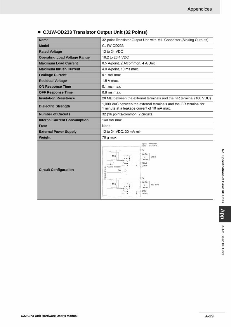
A-29
Appendices
CJ2 CPU Unit Hardware User’s Manual
A-1 Specifications of B
asic I/O U
nitsA
ppA
-1-2 Basic I/O
Units
� CJ1W-OD233 Transistor Output Unit (32 Points)Name 32-point Transistor Output Unit with MIL Connector (Sinking Outputs)
Model CJ1W-OD233
Rated Voltage 12 to 24 VDC
Operating Load Voltage Range 10.2 to 26.4 VDC
Maximum Load Current 0.5 A/point, 2 A/common, 4 A/Unit
Maximum Inrush Current 4.0 A/point, 10 ms max.
Leakage Current 0.1 mA max.
Residual Voltage 1.5 V max.
ON Response Time 0.1 ms max.
OFF Response Time 0.8 ms max.
Insulation Resistance 20 MΩ between the external terminals and the GR terminal (100 VDC)
Dielectric Strength 1,000 VAC between the external terminals and the GR terminal for 1 minute at a leakage current of 10 mA max.
Number of Circuits 32 (16 points/common, 2 circuits)
Internal Current Consumption 140 mA max.
Fuse None
External Power Supply 12 to 24 VDC, 30 mA min.
Weight 70 g max.
Circuit Configuration
OUT0
+V
OUT15
COM0
OUT0
+V
OUT15
COM1
COM0
COM1
SW
Wd m+1
Wd m to
to
Output indicator
Inte
rnal
circ
uits
AllocatedCIO word
Signalname

Appendices
A-30 CJ2 CPU Unit Hardware User’s Manual
Terminal Connections
• When wiring, pay careful attention to the polarity of the external power supply. The load may operate incorrectly if the polarity is reversed.
• Be sure to wire both terminals 23 and 24 (COM0).• Be sure to wire both terminals 3 and 4 (COM1).• Be sure to wire both terminals 21 and 22 (+V).• Be sure to wire both terminals 1 and 2 (+V).
40
38
36
34
32
30
28
26
24
22
20
18OUT0
16OUT1
14OUT2
12OUT3
10OUT4
8OUT5
6OUT6
4
+V2COM1
39
37
35
33
31
29
27
25
23
21
OUT8 19
OUT9 17
OUT10 15
OUT11 13
OUT12 11
OUT7
9OUT137OUT145OUT153
+V 1COM1
+V +V
L
L
L
L
L
L
L
L
L
L
L
L
L
L
L
L
L
L
L
L
L
L
L
L
L
L
L
L
LL
L
L OUT0
OUT1
OUT2
OUT3
OUT4
OUT5
OUT6
OUT7
OUT8
OUT9
OUT10
OUT11
OUT12
OUT13
OUT14
OUT15
COM0 COM0
Wd
m+1
Wd
m
Wd
m+1
Wd
m
12 to 24 VDC
12 to 24 VDC
Signalname
Signalname
Connec-tor pin
AllocatedCIO word
AllocatedCIO word

A-31
Appendices
CJ2 CPU Unit Hardware User’s Manual
A-1 Specifications of B
asic I/O U
nitsA
ppA
-1-2 Basic I/O
Units
� CJ1W-OD234 Transistor Output Unit (32 Points)Name 32-point Transistor Output Unit with MIL Connector (Sinking Outputs)
Model CJ1W-OD234
Rated Voltage 24 VDC
Operating Load Voltage Range 20.4 to 26.4 VDC
Maximum Load Current 0.5 A/point, 2 A/common, 4 A/Unit
Maximum Inrush Current 4.0 A/point, 10 ms max.
Leakage Current 0.1 mA max.
Residual Voltage 1.5 V max.
ON Response Time 15 μs max.
OFF Response Time 80 μs max.
Insulation Resistance 20 MΩ between the external terminals and the GR terminal (100 VDC)
Dielectric Strength 1,000 VAC between the external terminals and the GR terminal for 1 minute at a leakage current of 10 mA max.
Number of Circuits 32 (16 points/common, 2 circuits)
Internal Current Consumption 220 mA max.
Fuse None
External Power Supply 20.4 to 26.4 VDC, 110 mA min.
Weight 70 g max.
Circuit Configuration
OUT0+V
OUT15
COM0
OUT0+V
OUT15
COM1
COM0
COM1
SW
Wd m+1
Wd m to
to
Output indicator
Inte
rnal
circ
uits
AllocatedCIO word
Signalname

Appendices
A-32 CJ2 CPU Unit Hardware User’s Manual
Terminal Connections
• When wiring, pay careful attention to the polarity of the external power supply. The load may operate incorrectly if the polarity is reversed.
• Be sure to wire both terminals 23 and 24 (COM0).• Be sure to wire both terminals 3 and 4 (COM1).• Be sure to wire both terminals 21 and 22 (+V).• Be sure to wire both terminals 1 and 2 (+V).
40
38
36
34
32
30
28
26
24
22
20
18OUT0
16OUT1
14OUT2
12OUT3
10OUT4
8OUT5
6OUT6
4
+V2COM1
39
37
35
33
31
29
27
25
23
21
OUT8 19
OUT9 17
OUT10 15
OUT11 13
OUT12 11
OUT7
9OUT137OUT145OUT153
+V 1COM1
+V +V
L
L
L
L
L
L
L
L
L
L
L
L
L
L
L
L
L
L
L
L
L
L
L
L
L
L
L
L
LL
L
L OUT0
OUT1
OUT2
OUT3
OUT4
OUT5
OUT6
OUT7
OUT8
OUT9
OUT10
OUT11
OUT12
OUT13
OUT14
OUT15
COM0 COM0
Wd
m+1
Wd
m
Wd
m+1
Wd
m
24 VDC
24 VDC
Signalname
Signalname
Connec-tor pin
AllocatedCIO word
AllocatedCIO word

A-33
Appendices
CJ2 CPU Unit Hardware User’s Manual
A-1 Specifications of B
asic I/O U
nitsA
ppA
-1-2 Basic I/O
Units
� CJ1W-OD261 Transistor Output Unit (64 Points)Name 64-point Transistor Output Unit with Fujitsu Connectors (Sinking Outputs)
Model CJ1W-OD261
Rated Voltage 12 to 24 VDC
Operating Load Voltage Range
10.2 to 26.4 VDC
Maximum Load Current 0.3 A/point, 1.6 A/common, 6.4 A/Unit
Maximum Inrush Current 3.0 A/point, 10 ms max.
Leakage Current 0.1 mA max.
Residual Voltage 1.5 V max.
ON Response Time 0.5 ms max.
OFF Response Time 1.0 ms max.
Insulation Resistance 20 MΩ between the external terminals and the GR terminal (100 VDC)
Dielectric Strength 1,000 VAC between the external terminals and the GR terminal for 1 minute at a leakage current of 10 mA max.
Number of Circuits 64 (16 points/common, 4 circuits)
Internal Current Consump-tion
5 VDC, 170 mA max.
Fuse None
External Power Supply 10.2 to 26.4 VDC, 50 mA min.
Weight 110 g max.
Accessories None
Circuit Configuration
OUT0
+V
OUT15COM0
OUT0
+V
OUT15
COM2
COM0
COM2
+VOUT0
OUT15COM1COM1
+VOUT0
OUT15COM3COM3
CN1
SW
CN2
Output indicator
to
to
to
to
Wd m
Wd m+1
Wd m+2
Wd m+3
Inte
rnal
circ
uits
AllocatedCIO word
Signalname
Connector row A
Connector row B
Connector row A
Connector row B

Appendices
A-34 CJ2 CPU Unit Hardware User’s Manual
Terminal Connections
CN1 CN2
• When wiring, pay careful attention to the polarity of the external power supply. The load may operate incor-rectly if the polarity is reversed.
• Be sure to wire both terminals A9 and A19 (COM0) of CN1.
• Be sure to wire both terminals B9 and B19 (COM1) of CN1.
• Be sure to wire both terminals A10 and A20 (+V) of CN1.
• Be sure to wire both terminals B10 and B20 (+V) of CN1.
• When wiring, pay careful attention to the polarity of the external power supply. The load may operate incor-rectly if the polarity is reversed.
• Be sure to wire both terminals A9 and A19 (COM2) of CN2.
• Be sure to wire both terminals B9 and B19 (COM3) of CN2.
• Be sure to wire both terminals A10 and A20 (+V) of CN2.
• Be sure to wire both terminals B10 and B20 (+V) of CN2.
COM0
+V
COM0
+V
COM1
+V
OUT8
OUT9
OUT10
OUT11
OUT12
OUT13
OUT14
OUT15
COM1
+V
L
L
LL
L
LL
L
L
L
LL
L
LL
L
L
L
LL
L
LL
L
L
L
LL
L
LL
LOUT0
OUT1
OUT2
OUT3
OUT4
OUT5
OUT6
OUT7
OUT0
OUT1
OUT2
OUT3
OUT4
OUT5
OUT6
OUT7
OUT8
OUT9
OUT10
OUT11
OUT12
OUT13
OUT14
OUT15
A20
A19
A18
A17
A16
A15
A14
A13
A12
A11
A10
A9
A8
A7
A6
A5
A4
A3
A2
A1
B20
B19
B18
B17
B16
B15
B14
B13
B12
B11
B10
B9
B8
B7
B6
B5
B4
B3
B2
B1
12 to 24VDC
Wd
m
Wd
m+1
12 to 24VDC
Wd
m+1
Wd
m
Signalname
Signalname
Connec-tor pin Allocated
CIO wordAllocatedCIO word
COM3
+V
COM3
+V
COM2
+V
OUT8
OUT9
OUT10
OUT11
OUT12
OUT13
OUT14
OUT15
COM2
+V
L
L
LL
L
LL
L
L
L
LL
L
LL
L
L
L
LL
L
LL
L
L
L
LL
L
LL
L
OUT0
OUT1
OUT2
OUT3
OUT4
OUT5
OUT6
OUT7
OUT0
OUT1
OUT2
OUT3
OUT4
OUT5
OUT6
OUT7
OUT8
OUT9
OUT10
OUT11
OUT12
OUT13
OUT14
OUT15
A1
A2
A3
A4
A5
A6
A7
A8
A9
A10
A11
A12
A13
A14
A15
A16
A17
A18
A19
A20
B1
B2
B3
B4
B5
B6
B7
B8
B9
B10
B11
B12
B13
B14
B15
B16
B17
B18
B19
B20
12 to 24VDC
Wd
m+3
Wd
m+2
Wd
m+2
Wd
m+3
12 to 24VDC
Signalname
Signalname
Connec-tor pin Allocated
CIO wordAllocatedCIO word
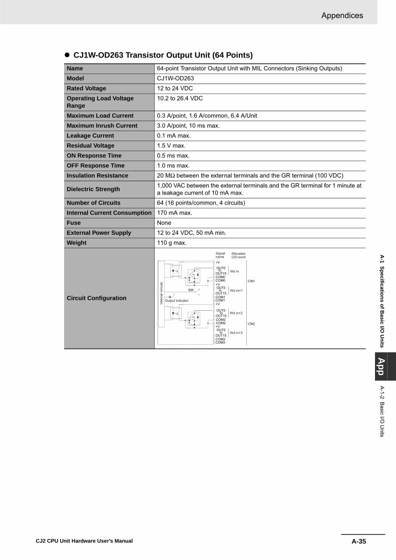
A-35
Appendices
CJ2 CPU Unit Hardware User’s Manual
A-1 Specifications of B
asic I/O U
nitsA
ppA
-1-2 Basic I/O
Units
� CJ1W-OD263 Transistor Output Unit (64 Points)Name 64-point Transistor Output Unit with MIL Connectors (Sinking Outputs)
Model CJ1W-OD263
Rated Voltage 12 to 24 VDC
Operating Load Voltage Range
10.2 to 26.4 VDC
Maximum Load Current 0.3 A/point, 1.6 A/common, 6.4 A/Unit
Maximum Inrush Current 3.0 A/point, 10 ms max.
Leakage Current 0.1 mA max.
Residual Voltage 1.5 V max.
ON Response Time 0.5 ms max.
OFF Response Time 1.0 ms max.
Insulation Resistance 20 MΩ between the external terminals and the GR terminal (100 VDC)
Dielectric Strength 1,000 VAC between the external terminals and the GR terminal for 1 minute at a leakage current of 10 mA max.
Number of Circuits 64 (16 points/common, 4 circuits)
Internal Current Consumption 170 mA max.
Fuse None
External Power Supply 12 to 24 VDC, 50 mA min.
Weight 110 g max.
Circuit Configuration
OUT0
+V
OUT15COM0
OUT0
+V
OUT15
COM2
COM0
COM2
+VOUT0
OUT15COM1COM1
+VOUT0
OUT15COM3COM3
CN1
SW
CN2
Inte
rnal
circ
uits
Output indicator
to
to
to
to
Wd m
Wd m+1
Wd m+2
Wd m+3
AllocatedCIO word
Signalname
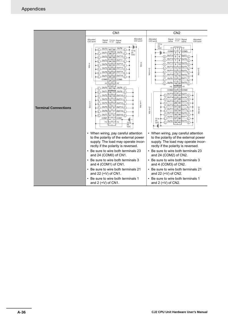
Appendices
A-36 CJ2 CPU Unit Hardware User’s Manual
Terminal Connections
CN1 CN2
• When wiring, pay careful attention to the polarity of the external power supply. The load may operate incor-rectly if the polarity is reversed.
• Be sure to wire both terminals 23 and 24 (COM0) of CN1.
• Be sure to wire both terminals 3 and 4 (COM1) of CN1.
• Be sure to wire both terminals 21 and 22 (+V) of CN1.
• Be sure to wire both terminals 1 and 2 (+V) of CN1.
• When wiring, pay careful attention to the polarity of the external power supply. The load may operate incor-rectly if the polarity is reversed.
• Be sure to wire both terminals 23 and 24 (COM2) of CN2.
• Be sure to wire both terminals 3 and 4 (COM3) of CN2.
• Be sure to wire both terminals 21 and 22 (+V) of CN2.
• Be sure to wire both terminals 1 and 2 (+V) of CN2.
1 +V3
5
7
9
11
13
15
17
19
21
23
25
27OUT15
29OUT14
31OUT13
33OUT12
35OUT11
37
+V
39
2
4+V
6
8
10
12
14
16
18
COM1
20
22
24
26
28
30
OUT10
32
34
36
38
40
COM1
+V
OUT0
OUT7
OUT6
OUT5
OUT4
OUT3
OUT2
OUT1
COM0
OUT8
OUT9
COM0
L
L
L
L
LL
L
L
L
L
L
L
LL
L
L
L
L
L
L
LL
L
L
L
L
L
L
LL
L
LOUT15
OUT14
OUT13
OUT12
OUT11
OUT10
OUT8
OUT9
OUT0
OUT7
OUT6
OUT5
OUT4
OUT3
OUT2
OUT1W
d m
Wd
mW
d m
+1
Wd
m+1
12 to 24VDC
12 to 24VDC
Signalname
Signalname
Connec-tor pin
AllocatedCIO word
AllocatedCIO word
40
38
36
34
32
30
28
26
24
22
20
18
16
14
12
10
8
6
4
+V2COM3
39
37
35
33
31
29
27
25
23
21
19
17
15
13
11
9
7
5
3
+V 1COM3
+V +V
COM2 COM2
L
L
L
L
LL
L
L
L
L
L
L
LL
L
L
L
L
L
L
LL
L
L
L
L
L
L
LL
L
L
OUT8
OUT9
OUT10
OUT11
OUT12
OUT13
OUT14
OUT15
OUT8
OUT9
OUT10
OUT11
OUT12
OUT13
OUT14
OUT15
OUT0
OUT1
OUT2
OUT3
OUT4
OUT5
OUT6
OUT7
OUT0
OUT1
OUT2
OUT3
OUT4
OUT5
OUT6
OUT7
Wd
m+3
Wd
m+3
Wd
m+2
Wd
m+2
12 to 24VDC
12 to 24VDC
Signalname
Signalname
Connec-tor pin
AllocatedCIO word
AllocatedCIO word

A-37
Appendices
CJ2 CPU Unit Hardware User’s Manual
A-1 Specifications of B
asic I/O U
nitsA
ppA
-1-2 Basic I/O
Units
� CJ1W-OD202 Transistor Output Unit (8 Points)Name 8-point Transistor Output Unit with Terminal Block (Sourcing Outputs)
Model CJ1W-OD202
Rated Voltage 24 VDC
Operating Load Voltage Range 20.4 to 26.4 VDC
Maximum Load Current 2 A/point, 8 A/Unit
Leakage Current 0.1 mA max.
Residual Voltage 1.5 V max.
ON Response Time 0.5 ms max.
OFF Response Time 1.0 ms max.
Load Short-circuit ProtectionDetection current: 6 A min.Automatic restart after error clearance. (Refer to page A-150.)
Line Disconnection Detection Detection current: 200 mA (Refer to page A-150.)
Insulation Resistance 20 MΩ between the external terminals and the GR terminal (100 VDC)
Dielectric Strength 1,000 VAC between the external terminals and the GR terminal for 1 minute at a leakage current of 10 mA max.
Number of Circuits 8 (4 points/common, 2 circuits)
Internal Current Consumption 110 mA max.
Fuse None
External Power Supply 24 VDC, 50 mA min.
Weight 120 g max.
Circuit Configuration
• The ERR indicator will light and the corresponding bit in A050 to A069 (Basic I/O Unit Information, two points per bit) will turn ON if an overcur-rent or line disconnection is detected.
COM0 (+V)
OUT3
OUT0
0 V
OUT4
OUT70 V
COM1 (+V)
Sho
rt-ci
rcui
tpr
otec
tion
Sho
rt-ci
rcui
tpr
otec
tion
to
to
Output indicator
ERR indicator
Inte
rnal
circ
uits
Signalname

Appendices
A-38 CJ2 CPU Unit Hardware User’s Manual
*1 Terminal numbers A0 to A8 and B0 to B8 are used in this manual, but they are not printed on theUnit.
Note Although 16 I/O bits (1 word) are allocated, only 8 of these can be used for external I/O. This Unit is alsotreated as a 16-point I/O Unit in the I/O tables.
Terminal Connections
• When wiring, pay careful attention to the polarity of the external power supply. The load may operate incorrectly if the polarity is reversed.
OUT0
OUT2
0V
NC
NC
OUT4
OUT6
B0
B1
B2
B3
B4
B5
B6
B7
B8
NC
A0 OUT1
OUT3
COM0 (+V)
NC
NC
NC
OUT5
OUT7
A1
A2
A3
A4
A5
A6
A7
A80V
COM1 (+V)
L
L
L
L
L
L
L
L
24 VDC
24 VDC
Signalname
Signalname
Connec-tor pin
*1

A-39
Appendices
CJ2 CPU Unit Hardware User’s Manual
A-1 Specifications of B
asic I/O U
nitsA
ppA
-1-2 Basic I/O
Units
� CJ1W-OD204 Transistor Output Unit (8 Points)
*1 Terminal numbers A0 to A8 and B0 to B8 are used in this manual, but they are not printed on theUnit.
Note Although 16 I/O bits (1 word) are allocated, only 8 of these can be used for external I/O. This Unit is alsotreated as a 16-point I/O Unit in the I/O tables.
Name 8-point Transistor Output Unit with Terminal Block (Sourcing Outputs)
Model CJ1W-OD204
Rated Voltage 24 VDC
Operating Load Voltage Range 20.4 to 26.4 VDC
Maximum Load Current 0.5 A/point, 4.0 A/Unit
Leakage Current 0.1 mA max.
Residual Voltage 1.5 V max.
ON Response Time 0.5 ms max.
OFF Response Time 1.0 ms max.
Load Short-circuit ProtectionDetection current: 0.7 to 2.5 AAutomatic restart after error clearance. (Refer to page A-150.)
Insulation Resistance 20 MΩ between the external terminals and the GR terminal (100 VDC)
Dielectric Strength 1,000 VAC between the external terminals and the GR terminal for 1 minute at a leakage current of 10 mA max.
Number of Circuits 8 (8 points/common, 1 circuit)
Internal Current Consumption 100 mA max.
Fuse None
External Power Supply 20.4 to 26.4 VDC, 40 mA min.
Weight 120 g max.
Circuit Configuration
• When overcurrent is detected, the ERR indicator will light, and the cor-responding flag in the Basic I/O Unit Information Area (A050 to A069) will turn ON.
Terminal Connections
• When wiring, pay careful attention to the polarity of the external power supply. The load may operate incorrectly if the polarity is reversed.
COM (+V)
OUT0
OUT70 V
Output indicator
ERR indicator
Inte
rnal
circ
uits to
Sho
rt-ci
rcui
t pr
otec
tion
Signalname
B1
OUT1
B2
OUT3
B3
OUT5
B4
OUT7
B5
B6
B7
B8
A1
OUT0
A2
OUT2
A3
OUT4
A4
OUT6
A5
NC
A6
A7
A80V
B0A0
COM (+V)
L
L
L
L
L
L
L
L
NC
NC
NC
NC
NC
NC
NC
24 VDC
Signalname
Signalname
Connec-tor pin
*1

Appendices
A-40 CJ2 CPU Unit Hardware User’s Manual
� CJ1W-OD212 Transistor Output Unit (16 Points)
*1 Terminal numbers A0 to A8 and B0 to B8 are used in this manual, but they are not printed on theUnit.
Name 16-point Transistor Output Unit with Terminal Block (Sourcing Outputs)
Model CJ1W-OD212
Rated Voltage 24 VDC
Operating Load Voltage Range 20.4 to 26.4 VDC
Maximum Load Current 0.5 A/point, 5.0 A/Unit
Maximum Inrush Current 0.1 mA max.
Leakage Current 1.5 V max.
ON Response Time 0.5 ms max.
OFF Response Time 1.0 ms max.
Load Short-circuit ProtectionDetection current: 0.7 to 2.5 AAutomatic restart after error clearance. (Refer to page A-150.)
Insulation Resistance 20 MΩ between the external terminals and the GR terminal (100 VDC)
Dielectric Strength 1,000 VAC between the external terminals and the GR terminal for 1 minute at a leakage current of 10 mA max.
Number of Circuits 16 (16 points/common, 1 circuit)
Internal Current Consumption 5 VDC, 100 mA max.
External Power Supply 20.4 to 26.4 VDC, 40 mA min.
Weight 120 g max.
Circuit Configuration
• When overcurrent is detected, the ERR indicator will light, and the corre-sponding flag in the Basic I/O Unit Information Area (A050 to A069) will turn ON.
Terminal Connections
• When wiring, pay careful attention to the polarity of the external power supply. The load may operate incorrectly if the polarity is reversed.
OUT15 OUT0
0 V
COM (+V)
Inte
rnal
circ
uits
Output indicator
ERR indicator
Sho
rt-ci
rcui
tpr
otec
tion
to
Signalname
B1
OUT1
B2
OUT3
B3
OUT5
B4
OUT7
B5
OUT9
B6
OUT11
B7
OUT13
B8
OUT15
24 VDC
A1
OUT0
A2
OUT2
A3
OUT4
A4
OUT6
A5
OUT8
A6
OUT10
A7
OUT12
A8
OUT14
0 V
B0A0L
L
L
L
L
L
L
L
L
L
L
L
L
L
L
LCOM (+V)
Signalname
Signalname
Connec-tor pin
*1
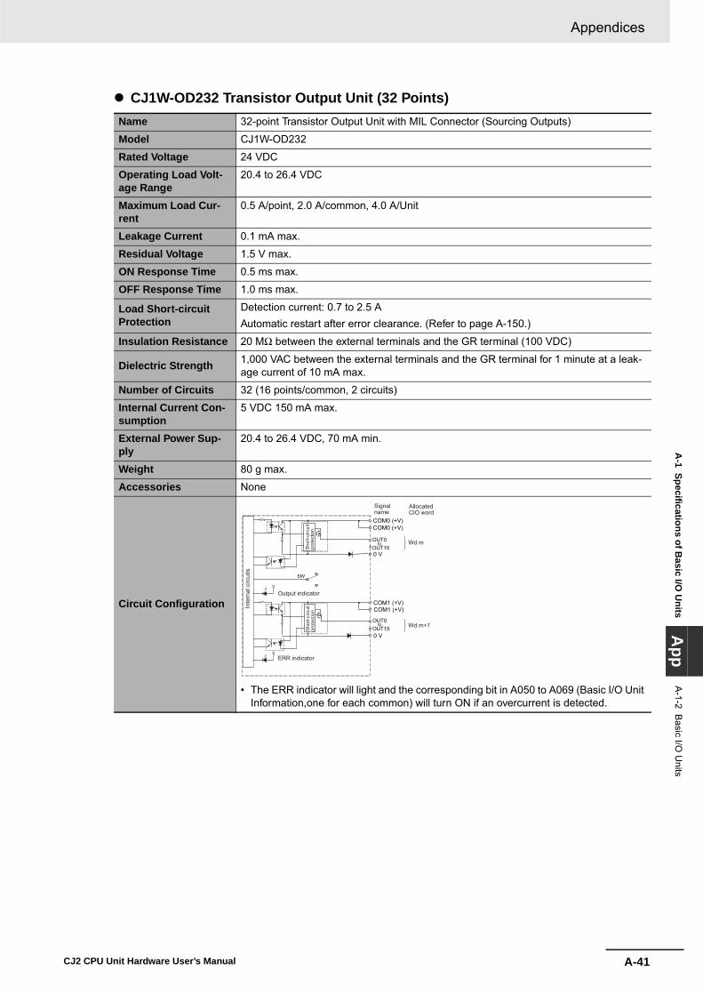
A-41
Appendices
CJ2 CPU Unit Hardware User’s Manual
A-1 Specifications of B
asic I/O U
nitsA
ppA
-1-2 Basic I/O
Units
� CJ1W-OD232 Transistor Output Unit (32 Points)Name 32-point Transistor Output Unit with MIL Connector (Sourcing Outputs)
Model CJ1W-OD232
Rated Voltage 24 VDC
Operating Load Volt-age Range
20.4 to 26.4 VDC
Maximum Load Cur-rent
0.5 A/point, 2.0 A/common, 4.0 A/Unit
Leakage Current 0.1 mA max.
Residual Voltage 1.5 V max.
ON Response Time 0.5 ms max.
OFF Response Time 1.0 ms max.
Load Short-circuit Protection
Detection current: 0.7 to 2.5 AAutomatic restart after error clearance. (Refer to page A-150.)
Insulation Resistance 20 MΩ between the external terminals and the GR terminal (100 VDC)
Dielectric Strength 1,000 VAC between the external terminals and the GR terminal for 1 minute at a leak-age current of 10 mA max.
Number of Circuits 32 (16 points/common, 2 circuits)
Internal Current Con-sumption
5 VDC 150 mA max.
External Power Sup-ply
20.4 to 26.4 VDC, 70 mA min.
Weight 80 g max.
Accessories None
Circuit Configuration
• The ERR indicator will light and the corresponding bit in A050 to A069 (Basic I/O Unit Information,one for each common) will turn ON if an overcurrent is detected.
OUT15OUT0
0 V
0 V
SW
COM0 (+V)COM0 (+V)
COM1 (+V)COM1 (+V)
Wd m
Wd m+1
to
OUT15OUT0
to
Output indicator
Inte
rnal
circ
uits
ERR indicator
Sho
rt-ci
rcui
tpr
otec
tion
Sho
rt-ci
rcui
tpr
otec
tion
AllocatedCIO word
Signalname

Appendices
A-42 CJ2 CPU Unit Hardware User’s Manual
Terminal Connections
• When wiring, pay careful attention to the polarity of the external power supply. The load may operate incorrectly if the polarity is reversed.
• Be sure to wire both terminals 21 and 22 (COM0 (+V)). • Be sure to wire both terminals 1 and 2 (COM1 (+V)).• Be sure to wire both terminals 3 and 4 (0 V).• Be sure to wire both terminals 23 and 24 (0 V).
OUT0
OUT1
OUT2
OUT3
OUT4
OUT5
OUT6
OUT7
0 V
COM1 (+V)
OUT8
OUT9
OUT10
OUT11
OUT12
OUT13
OUT14
OUT15
0 V
40
38
36
34
32
30
28
26
24
22
20
18
16
14
12
10
8
6
4
2
39
37
35
33
31
29
27
25
23
21
19
17
15
13
11
9
7
5
3
1COM1 (+V)
L
0 V
COM0 (+V)
0 V
COM0 (+V)
L
L
L
L
L
L
L
L
L
L
L
L
L
L
L
L
L
L
L
L
L
L
L
L
L
L
L
L
L
L
LOUT0
OUT1
OUT2
OUT3
OUT4
OUT5
OUT6
OUT7
OUT8
OUT9
OUT10
OUT11
OUT12
OUT13
OUT14
OUT15
Wd
m+1
Wd
m+1
Wd
m
Wd
m
24 VDC
24 VDC
Signalname
Signalname
Connec-tor pin
AllocatedCIO word
AllocatedCIO word

A-43
Appendices
CJ2 CPU Unit Hardware User’s Manual
A-1 Specifications of B
asic I/O U
nitsA
ppA
-1-2 Basic I/O
Units
� CJ1W-OD262 Transistor Output Unit (64 Points)Name 64-point Transistor Output Unit with MIL Connectors (Sourcing Outputs)
Model CJ1W-OD262
Rated Voltage 12 to 24 VDC
Operating Load Volt-age Range
10.2 to 26.4 VDC
Maximum Load Cur-rent
0.3 A/point, 1.6 A/common, 6.4 A/Unit
Maximum Inrush Cur-rent
3.0 A/point, 10 ms max.
Leakage Current 0.1 mA max.
Residual Voltage 1.5 V max.
ON Response Time 0.5 ms max.
OFF Response Time 1.0 ms max.
Insulation Resistance 20 MΩ between the external terminals and the GR terminal (100 VDC)
Dielectric Strength 1,000 VAC between the external terminals and the GR terminal for 1 minute at a leak-age current of 10 mA max.
Number of Circuits 64 (16 points/common, 4 circuits)
Internal Current Con-sumption
170 mA max. (5 VDC)
Fuse None
External Power Sup-ply
10.2 to 26.4 VDC, 50 mA min.
Weight 110 g max.
Accessories None
Circuit Configuration
OUT150 V
OUT0
COM0COM0
0 V
0 V
COM1
0 V
COM1
OUT15
OUT0
COM2COM2
OUT15
OUT0
OUT15
OUT0
COM3COM3
CN1 (OUT)
CN2 (OUT)
Wd m
Wd m+1
Wd m+3
Wd m+2
Inte
rnal
circ
uits Indicator switch
Output indicator
to
to
to
to
AllocatedCIO word
Signalname

Appendices
A-44 CJ2 CPU Unit Hardware User’s Manual
Terminal Connections
CN1 CN2
• When wiring, pay careful attention to the polarity of the external power supply. The load may operate incorrectly if the polarity is reversed.
• Be sure to wire both terminals 21 and 22 (COM0 (+V)) of CN1.
• Be sure to wire both terminals 1 and 2 (COM1 (+V)) of CN1.
• Be sure to wire both terminals 23 and 24 (0 V) of CN1.
• Be sure to wire both terminals 3 and 4 (0 V) of CN1.
• When wiring, pay careful attention to the polarity of the external power supply. The load may operate incorrectly if the polarity is reversed.
• Be sure to wire both terminals 21 and 22 (COM2 (+V)) of CN2.
• Be sure to wire both terminals 1 and 2 (COM3 (+V)) of CN2.
• Be sure to wire both terminals 23 and 24 (0 V) of CN2.
• Be sure to wire both terminals 3 and 4 (0 V) of CN2.
13
5
7
9
11
13
15
17
19
21
23
25
27
29
31
33
35
37
39
24
6
8
10
12
14
16
18
20
22
24
26
28
30
32
34
36
38
40L L
L L
L L
L L
L L
L L
L L
L L
L L
L L
L L
L L
L L
L L
L L
L LOUT15
OUT14
OUT13
OUT12
OUT11
OUT10OUT2
OUT15
OUT14
OUT13
OUT12
OUT11
0 V
0 V
OUT7
OUT6
OUT5
OUT4
OUT3
COM1 (+V)
OUT10
0 V
OUT0
OUT7
OUT6
OUT5
OUT4
OUT3OUT2
OUT1
COM0 (+V)
OUT8
OUT9
COM0 (+V)
OUT8
OUT9
OUT0
OUT1
0 V
COM1 (+V)
Wd
m
12 to 24 VDC
Wd
m+1
Wd
mW
d m
+1
12 to 24 VDC
Signalname
Signalname
Connec-tor pin
AllocatedCIO word
AllocatedCIO word
L L
L L
L L
L L
L L
L L
L L
L L
L L
L L
L L
L L
40OUT0
38OUT1
36OUT2
34OUT3
32OUT4
30OUT5
28OUT6
26OUT7
24
22
OUT15
20
18OUT0
16OUT1
14OUT2
12OUT3
10OUT4
8OUT5
6OUT6
4
2
39
37OUT8
35OUT9
33OUT10
31OUT11
29OUT12
27OUT13
25OUT14
23
21
OUT819
OUT917
OUT1015
OUT1113
OUT1210
OUT7
9OUT13
7OUT14
5OUT15
30 V
1COM3 (+V)
0 V
COM2 (+V)
0 V
COM3 (+V)
LL
0 V
COM2 (+V)L L
L
L L
L
Wd
m+3
Wd
m+2
12 to 24 VDC
12 to 24 VDC
Wd
m+3
Wd
m+2
Signalname
Signalname
Connec-tor pin
AllocatedCIO word
AllocatedCIO word
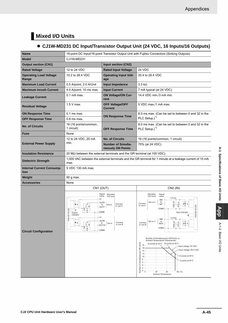
A-45
Appendices
CJ2 CPU Unit Hardware User’s Manual
A-1 Specifications of B
asic I/O U
nitsA
ppA
-1-2 Basic I/O
Units
� CJ1W-MD231 DC Input/Transistor Output Unit (24 VDC, 16 Inputs/16 Outputs)
Mixed I/O Units
Name 16-point DC Input/16-point Transistor Output Unit with Fujitsu Connectors (Sinking Outputs)
Model CJ1W-MD231
Output section (CN1) Input section (CN2)
Rated Voltage 12 to 24 VDC Rated Input Voltage 24 VDC
Operating Load Voltage Range
10.2 to 26.4 VDC Operating Input Volt-age
20.4 to 26.4 VDC
Maximum Load Current 0.5 A/point, 2.0 A/Unit Input Impedance 3.3 kΩ
Maximum Inrush Current 4.0 A/point, 10 ms max. Input Current 7 mA typical (at 24 VDC)
Leakage Current 0.1 mA max. ON Voltage/ON Cur-rent
14.4 VDC min./3 mA min.
Residual Voltage 1.5 V max. OFF Voltage/OFF Current
5 VDC max./1 mA max.
ON Response Time 0.1 ms max.ON Response Time
8.0 ms max. (Can be set to between 0 and 32 in the PLC Setup.)*1OFF Response Time 0.8 ms max.
No. of Circuits 16 (16 points/common, 1 circuit) OFF Response Time
8.0 ms max. (Can be set to between 0 and 32 in the PLC Setup.)*1
Fuse None
External Power Supply12 to 24 VDC, 20 mA min.
No. of Circuits 16 (16 points/common, 1 circuit)
Number of Simulta-neously ON Points
75% (at 24 VDC)
Insulation Resistance 20 MΩ between the external terminals and the GR terminal (at 100 VDC)
Dielectric Strength 1,000 VAC between the external terminals and the GR terminal for 1 minute at a leakage current of 10 mA max.
Internal Current Consump-tion
5 VDC 130 mA max.
Weight 90 g max.
Accessories None
Circuit Configuration
CN1 (OUT) CN2 (IN)
OUT0
+V
OUT7
OUT8
+V
OUT15
COM0
COM0
Inte
rnal
circ
uits
Outputindicator
to
to
Wd m
Wd m
AllocatedCIO word
Signalname
Connector row A
Connector row B
IN8
IN15
COM1
IN0
IN7
COM1
3.3 kΩ
3.3 kΩ
1000
pF
470
Ω
1000
pF
470
Ω
to
to
Input indicator
Inte
rnal
circ
uits
Wd m+1
Wd m+1
AllocatedCIO word
Signalname
Connector row A
Connector row B
02
4
6
810
12
14
16
18
0 20 40 60 (°C)
Number of Simultaneously ON Points vs. Ambient Temperature Characteristic
16 points at 33°C 16 points at 45°C
Num
ber o
f sim
ulta
neou
sly
ON
poi
nts
Input voltage: 24 VDC
Input voltage: 26.4 VDC
12 points at 55°C
9 points at 55°C
Ambient Temperature

Appendices
A-46 CJ2 CPU Unit Hardware User’s Manual
*1 The ON response time will be 20 μs maximum and OFF response time will be 400 μs maximum even if the responsetimes are set to 0 ms due to internal element delays.
Terminal Connections
CN1 (OUT) CN2 (IN)
• When wiring, pay careful attention to the polarity of the external power supply. The load may oper-ate incorrectly if polarity is reversed.
• Be sure to wire both pins A9 and B9 (COM0 (0 V)) of CN1.
• Be sure to wire both pins A10 and B10 (+V) of CN1.
• When wiring, pay careful attention to the polarity of the external power supply. The load may operate incorrectly if polarity is reversed.
• Be sure to wire both pins A9 and B9 (COM1) of CN2, and set the same polarity for both pins.
A1
A2
A3
A4
A5
A6
A7
A8
OUT0
OUT1
OUT2
OUT3
OUT4
OUT5
OUT6
OUT7A9
A10
A11
A12 NC
NC
COM0 (0V)
+V
B1
B2
B3
B4
B5
B6
B7
B8
B9
OUT9
OUT10
OUT11
OUT12
OUT13
OUT14
OUT15
OUT8
B10
B11
B12
L
L
L
L
L
L
L
L
L
L
L
L
L
L
L
L
NC
COM0 (0V)
+V
NC
12 to 24VDC
Wd
m
Wd
m
Signalname
Signalname
Connec-tor pinAllocated
CIO wordAllocatedCIO word
B12
B11
B10
B9
B8
B7
B6
B5
IN15
IN14
IN13
IN12
IN11
IN10
IN9
IN8
B4
B3
B2
B1
A12
A11
A10
A9
A8
A7
A6
A5
A4
IN6
IN5
IN4
IN3
IN2
IN1
IN0
IN7
A3
A2
A1
NC
COM1
NC
NC
NC
NC
COM1
NC
24 VDC
Wd
m+1
Wd
m+1
Signalname
SignalnameConnec-
tor pinAllocatedCIO word
AllocatedCIO word

A-47
Appendices
CJ2 CPU Unit Hardware User’s Manual
A-1 Specifications of B
asic I/O U
nitsA
ppA
-1-2 Basic I/O
Units
� CJ1W-MD233 DC Input/Transistor Output Unit (24 VDC, 16 Inputs/16 Outputs)Name 16-point DC Input/16-point Transistor Output Unit with MIL Connectors (Sinking Outputs)
Model CJ1W-MD233
Output section (CN1) Input section (CN2)
Rated Voltage 12 to 24 VDC Rated Input Volt-age
24 VDC
Operating Load Voltage Range
10.2 to 26.4 VDC Operating Input Voltage
20.4 to 26.4 VDC
Maximum Load Current 0.5 A/point, 2.0 A/Unit Input Impedance 3.3 kΩ
Maximum Inrush Current 4.0 A/point, 10 ms max. Input Current 7 mA typical (at 24 VDC)
Leakage Current 0.1 mA max. ON Voltage/ON Current
14.4 VDC min./3 mA min.
Residual Voltage 1.5 V max. OFF Voltage/OFF Current
5 VDC max./1 mA max.
ON Response Time 0.1 ms max. ON Response Time
8.0 ms max. (Can be set to between 0 and 32 in the PLC Setup.)*1OFF Response Time 0.8 ms max.
No. of Circuits 16 (16 points/common, 1 circuit) OFF Response
Time
8.0 ms max. (Can be set to between 0 and 32 in the PLC Setup.)*1
Fuse None
External Power Supply
12 to 24 VDC, 20 mA min. No. of Circuits 16 (16 points/common, 1 circuit)
Number of Simul-taneously ON Points
75% (at 24 VDC)
Insulation Resistance 20 MΩ between the external terminals and the GR terminal (at 100 VDC)
Dielectric Strength 1,000 VAC between the external terminals and the GR terminal for 1 minute at a leakage current of 10 mA max.
Internal Current Consump-tion
5 VDC 130 mA max.
Weight 90 g max.
Accessories None
Circuit Configuration
CN1 (OUT) CN2 (IN)
OUT0
+V
OUT7
OUT8
+V
OUT15
COM0
COM0
Inte
rnal
circ
uits
to
to
Outputindicator
Wd m
Wd m
AllocatedCIO word
Signalname
IN0
IN7
COM1
IN8
IN15
COM1
Wd m+1
Wd m+1
3.3 kΩ
3.3 kΩ
1000
pF
470
Ω
1000
pF
470
Ω
to
to
Input indicator
Inte
rnal
circ
uits
AllocatedCIO word
Signalname
024681012141618
0 20 40 60 (°C)
Number of Simultaneously ON Points vs. Ambient Temperature Characteristic
Num
ber o
f sim
ulta
neou
sly
ON
poi
nts
Ambient Temperature
Input voltage: 24 VDC
Input voltage: 26.4 VDC
12 points at 55°C
9 points at 55°C
16 points at 33°C 16 points at 45°C

Appendices
A-48 CJ2 CPU Unit Hardware User’s Manual
*1 The ON response time will be 20 μs maximum and OFF response time will be 400 μs maximum even if the responsetimes are set to 0 ms due to internal element delays.
Terminal Connections
CN1 (OUT) CN2 (IN)
• When wiring, pay careful attention to the polarity of the external power supply. The load may oper-ate incorrectly if polarity is reversed.
• Be sure to wire both terminals 3 and 4 (COM0 (0 V)) of CN1.
• Be sure to wire both terminals 1 and 2 (+V) of CN1.
• When wiring, pay careful attention to the polarity of the external power supply. The load may operate incorrectly if polarity is reversed.
• Be sure to wire both pins 3 and 4 (COM1) of CN2, and set the same polarity for both pins.
1
3
5
7
9
11
13
15
OUT15
OUT14
OUT13
OUT12
OUT11
OUT10
OUT9
OUT8
17
19
COM0 (0V)
+V2
4
6
8
10
12
14
16
18
OUT6
OUT5
OUT4
OUT3
OUT2
OUT1
OUT0
OUT7
20
COM0 (0V)
+V
L
L
L
L
L
L
L
L
L
L
L
L
L
L
L
L
12 to 24 VDC
Wd
m
Wd
m
Signalname
Signalname
Connec-tor pin
AllocatedCIO word
AllocatedCIO word
20
18
16
14
12
10
8
6
4
2
19
17
15
13
11
9
7 IN6
IN5
IN4
IN3
IN2
IN1
IN0
IN7 5
3
1
IN15
IN14
IN13
IN12
IN11
IN10
IN9
IN8
COM1
NC
COM1
NC
24 VDC
Wd
m+1
Wd
m+1
Signalname
Signalname
Connec-tor pinAllocated
CIO wordAllocatedCIO word

A-49
Appendices
CJ2 CPU Unit Hardware User’s Manual
A-1 Specifications of B
asic I/O U
nitsA
ppA
-1-2 Basic I/O
Units
� CJ1W-MD261 DC Input/Transistor Output Unit (24 VDC 32 Inputs/32 Outputs)Name 32-point DC Input/32-point Transistor Output Unit with Fujitsu Connectors (Sinking Outputs)
Model CJ1W-MD261
Output section (CN1) Input section (CN2)
Rated Voltage 12 to 24 VDC Rated Input Voltage 24 VDC
Operating Load Voltage Range
10.2 to 26.4 VDC Operating Input Voltage
20.4 to 26.4 VDC
Maximum Load Current
0.3 A/point, 1.6 A/common, 3.2 A/Unit Input Impedance 5.6 kΩ
Maximum Inrush Current
3.0 A/point, 10 ms max. Input Current 4.1 mA typical (at 24 VDC)
Leakage Current 0.1 mA max. ON Voltage/ON Cur-rent
19.0 VDC min./3 mA min. *2
Residual Voltage 1.5 V max. OFF Voltage/OFF Current
5 VDC max./1 mA max.
ON Response Time
0.5 ms max.
ON Response Time
8.0 ms max. (Can be set to between 0 and 32 in the PLC Setup.)*1
OFF Response Time
1.0 ms max.
No. of Circuits 32 (16 points/common, 2 circuits) OFF Response Time
8.0 ms max. (Can be set to between 0 and 32 in the PLC Setup.)*1Fuse None
External Power Supply
12 to 24 VDC, 30 mA min. No. of Circuits 32 (16 points/common, 2 circuits)
Number of Simulta-neously ON Points
75% (24 points) (at 24 VDC)
Insulation Resis-tance
20 MΩ between the external terminals and the GR terminal (at 100 VDC)
Dielectric Strength 1,000 VAC between the external terminals and the GR terminal for 1 minute at a leakage current of 10 mA max.
Internal Current Consumption
5 VDC 140 mA max.
Weight 110 g max.
Accessories None
Circuit Configura-tion
CN1 (OUT) CN2 (IN)
0
5
10
15
20
25
30
35
0 20 40 60 (°C)
Number of Simultaneously ON Points vs. Ambient Temperature Characteristic
Num
ber o
f sim
ulta
neou
sly
ON
poi
nts 32 points at 38°C 32 points at 44°C
Ambient Temperature
Input voltage: 24 VDC
Input voltage: 26.4 VDC
12 points/commonat 55°C
8 points/commonat 55°C
OUT0
+V
OUT15 COM0
OUT0
+V
OUT15
COM1
COM0
COM1
Inte
rnal
circ
uits
to
to
Outputindicator Indicator
switch
Wd m
Wdm+1
AllocatedCIO word
Signalname
Connector row A
Connector row B
IN0
IN15
COM2
IN0
IN15
COM3
COM2
COM3
5.6 kΩ
560
Ω
1000
pF
5.6 kΩ
560
Ω
1000
pFto
to
Indicator switchInput indicator
Inte
rnal
circ
uits
Wdm+2
Wdm+3
AllocatedCIO word
Signalname
Connector row A
Connector row B
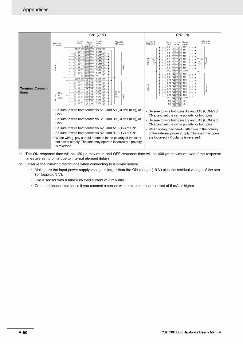
Appendices
A-50 CJ2 CPU Unit Hardware User’s Manual
*1 The ON response time will be 120 μs maximum and OFF response time will be 400 μs maximum even if the responsetimes are set to 0 ms due to internal element delays.
*2 Observe the following restrictions when connecting to a 2-wire sensor. • Make sure the input power supply voltage is larger than the ON voltage (19 V) plus the residual voltage of the sen-
sor (approx. 3 V). • Use a sensor with a minimum load current of 3 mA min. • Connect bleeder resistance if you connect a sensor with a minimum load current of 5 mA or higher.
Terminal Connec-tions
CN1 (OUT) CN2 (IN)
• Be sure to wire both terminals A19 and A9 (COM0 (0 V)) of CN1.
• Be sure to wire both terminals B19 and B9 (COM1 (0 V)) of CN1.
• Be sure to wire both terminals A20 and A10 (+V) of CN1.• Be sure to wire both terminals B20 and B10 (+V) of CN1.• When wiring, pay careful attention to the polarity of the exter-
nal power supply. The load may operate incorrectly if polarity is reversed.
• Be sure to wire both pins A9 and A18 (COM2) of CN2, and set the same polarity for both pins.
• Be sure to wire both pins B9 and B18 (COM3) of CN2, and set the same polarity for both pins.
• When wiring, pay careful attention to the polarity of the external power supply. The load may oper-ate incorrectly if polarity is reversed.
A1A2A3A4A5A6A7A8
OUT0 OUT1 OUT2 OUT3 OUT4 OUT5 OUT6 OUT7
A9A10A11A12A13A14A15A16A17A18
OUT8 OUT9 OUT10 OUT11 OUT12 OUT13 OUT14 OUT15
A19A20
B1B2B3B4B5B6B7B8
OUT0 OUT1 OUT2 OUT3 OUT4 OUT5 OUT6 OUT7
B9B10 +V +V B11B12B13B14B15B16B17B18
OUT8 OUT9 OUT10 OUT11 OUT12 OUT13 OUT14 OUT15
B19 COM0 (0V) COM1 (0V) B20 +V +V
L
LLLLLLL
LLLLL
LLL
LLLLL
LLL
LLLLLLLL
COM0 (0V) COM1 (0V)
Wd
m+1
Wd
m
Wd
m+1
12 to 24VDC
Wd
m
12 to 24VDC
Signalname
Signalname
Connec-tor pinAllocated
CIO word
AllocatedCIO word
B1 IN0
B2 IN1
B3 IN2
B4 IN3
B5 IN4
B6 IN5
B7 IN6
B8 IN7
B9B10 IN8
B11 IN9
B12 IN10
B13 IN11
B14 IN12
B15 IN13
B16 IN14
B17 IN15
B18 B19 NC
B20 NC
A1IN0
A2IN1
A3IN2
A4IN3
A5IN4
A6IN5
A7IN6
A8IN7
A9A10 IN8
A11 IN9
A12 IN10
A13 IN11
A14 IN12
A15 IN13
A16 IN14
A17 IN15COM2 COM3
COM2 COM3
A18 A19 NC
A20 NC
Wd
m+2
Wd
m+3
Wd
m+2
Wd
m+3
24VDC
24VDC
Signalname
Signalname
Connec-tor pin
AllocatedCIO word
AllocatedCIO word

A-51
Appendices
CJ2 CPU Unit Hardware User’s Manual
A-1 Specifications of B
asic I/O U
nitsA
ppA
-1-2 Basic I/O
Units
� CJ1W-MD263 DC Input/Transistor Output Unit (24 VDC 32 Inputs/32 Outputs)Name 32-point DC Input/32-point Transistor Output Unit with MIL Connectors (Sinking Outputs)
Model CJ1W-MD263
Output section (CN1) Input section (CN2)
Rated Voltage 12 to 24 VDC Rated Input Voltage 24 VDC
Operating Load Voltage Range
10.2 to 26.4 VDC Operating Input Voltage
20.4 to 26.4 VDC
Maximum Load Current
0.3 A/point, 1.6 A/common, 3.2 A/Unit Input Impedance 5.6 kΩ
Maximum Inrush Current
3.0 A/point, 10 ms max. Input Current 4.1 mA typical (at 24 VDC)
Leakage Current 0.1 mA max. ON Voltage/ON Cur-rent
19.0 VDC min./3 mA min.*2
Residual Voltage 1.5 V max. OFF Voltage/OFF Current
5 VDC max./1 mA max.
ON Response Time
0.5 ms max.
ON Response Time
8.0 ms max. (Can be set to between 0 and 32 in the PLC Setup.)*1
OFF Response Time
1.0 ms max.
No. of Circuits 32 (16 points/common, 2 circuits)OFF Response Time
8.0 ms max. (Can be set to between 0 and 32 in the PLC Setup.)*1Fuse None
External Power Supply
12 to 24 VDC, 30 mA min. No. of Circuits 32 (16 points/common, 2 circuits)
Number of Simulta-neously ON Points
75% (24 points) (at 24 VDC)
Insulation Resis-tance
20 MΩ between the external terminals and the GR terminal (at 100 VDC)
Dielectric Strength 1,000 VAC between the external terminals and the GR terminal for 1 minute at a leakage current of 10 mA max.
Internal Current Consumption
5 VDC 140 mA max.
Weight 110 g max.
Accessories None
Circuit Configura-tion
CN1 (OUT) CN2 (IN)
0
5
10
15
20
25
30
35
0 20 40 60 (°C)
Number of Simultaneously ON Points vs. Ambient Temperature Characteristic
Num
ber o
f sim
ulta
neou
sly
ON
poi
nts 32 points at 38°C 32 points at 44°C
Ambient Temperature
Input voltage: 24 VDC
Input voltage: 26.4 VDC
12 points/commonat 55°C
8 points/commonat 55°C
OUT0
+V
OUT15
COM0
OUT0
+V
OUT15
COM1
COM0
COM1
Inte
rnal
circ
uits
Outputindicator Indicator
switch
to
to
Wd m
Wd m+1
AllocatedCIO word
Signalname
IN0
IN15
COM2
IN0
IN15
COM3
COM2
COM3
5.6 kΩ
560
Ω
1000
pF
5.6 kΩ
560
Ω
1000
pF Inte
rnal
circ
uitsIndicator switch
Input indicator
to
to
Wd m+2
Wd m+3
AllocatedCIO word
Signalname

Appendices
A-52 CJ2 CPU Unit Hardware User’s Manual
*1 The ON response time will be 120 μs maximum and OFF response time will be 400 μs maximum even if the responsetimes are set to 0 ms due to internal element delays.
Note Observe the following restrictions when connecting to a 2-wire sensor. • Make sure the input power supply voltage is larger than the ON voltage (19 V) plus the residual voltage of the sen-
sor (approx. 3 V). • Use a sensor with a minimum load current of 3 mA min. • Connect bleeder resistance if you connect a sensor with a minimum load current of 5 mA or higher.
Terminal Connec-tions
CN1 (OUT) CN2 (IN)
• Be sure to wire both terminals 23 and 24 (COM0) of CN1.• Be sure to wire both terminals 3 and 4 (COM1) of CN1.• Be sure to wire both terminals 21 and 22 (+V) of CN1.• Be sure to wire both terminals 1 and 2 (+V) of CN1.• When wiring, pay careful attention to the polarity of the exter-
nal power supply. The load may operate incorrectly if polarity is reversed.
• Be sure to wire both pins 23 and 24 (COM2) of CN2, and set the same polarity for both pins.
• Be sure to wire both pins 3 and 4 (COM3) of CN2, and set the same polarity for both pins.
• When wiring, pay careful attention to the polarity of the external power supply. The load may oper-ate incorrectly if polarity is reversed.
1 +V 35 OUT15 7 OUT14 9 OUT13 11 OUT12 13 OUT11 15 OUT10 1719
OUT2
21232527
OUT15
29OUT14
31OUT13
33OUT12
35OUT11
37
+V
39
24
+V
68
OUT7
10 OUT6
12 OUT5
14 OUT4
16 OUT3
18
COM1
20 22 24 26 28 30
OUT10
32 34 36 38 40
COM1
+V
OUT0
OUT7OUT6OUT5OUT4OUT3OUT2OUT1
COM0
OUT8 OUT9
COM0
OUT8 OUT9
OUT0OUT1
LLLLLLLL
LLLLLLLL
LLLLLLLL
LLLLLLLL
Wd
mW
d m
+1
12 to 24 VDC
12 to 24VDC
Wd
mW
d m
+1
Signalname
Signalname
Connec-tor pin
AllocatedCIO word
AllocatedCIO word
40 IN0 38 IN1 36 IN2 34 IN3 32 IN4 30 IN5 28 IN6 26 IN7 24 22
IN15
20 18
IN0
16 IN1
14 IN2
12 IN3
10 IN4
8IN5
6IN6
4
NC2COM3
39 37
IN8
35 IN9
33 IN10
31 IN11
29 IN12
27 IN13
25 IN14
23 COM221
IN8NC NC
19
IN9 17
IN10 15
IN11 13
IN12 11
IN7
9IN137IN145IN153
NC 1COM3
COM2
24 VDC
Wd
m+3
Wd
m+2
24 VDC
Wd
m+3
Wd
m+2
Signalname
Signalname
Connec-tor pin
AllocatedCIO word
AllocatedCIO word
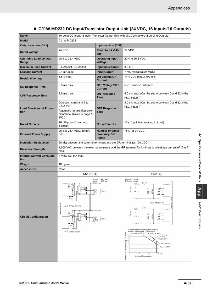
A-53
Appendices
CJ2 CPU Unit Hardware User’s Manual
A-1 Specifications of B
asic I/O U
nitsA
ppA
-1-2 Basic I/O
Units
� CJ1W-MD232 DC Input/Transistor Output Unit (24 VDC, 16 inputs/16 Outputs)Name 16-point DC Input/16-point Transistor Output Unit with MIL Connectors (Sourcing Outputs)
Model CJ1W-MD232
Output section (CN1) Input section (CN2)
Rated Voltage 24 VDC Rated Input Volt-age
24 VDC
Operating Load Voltage Range
20.4 to 26.4 VDC Operating Input Voltage
20.4 to 26.4 VDC
Maximum Load Current 0.5 A/point, 2.0 A/Unit Input Impedance 3.3 kΩ
Leakage Current 0.1 mA max. Input Current 7 mA typical (at 24 VDC)
Residual Voltage 1.5 V max. ON Voltage/ON Current
14.4 VDC min./3 mA min.
ON Response Time 0.5 ms max. OFF Voltage/OFF Current
5 VDC max./1 mA max.
OFF Response Time1.0 ms max. ON Response
Time8.0 ms max. (Can be set to between 0 and 32 in the PLC Setup.)*1
Load Short-circuit Protec-tion
Detection current: 0.7 to 2.5 A min.Automatic restart after error clearance. (Refer to page A-150.)
OFF Response Time
8.0 ms max. (Can be set to between 0 and 32 in the PLC Setup.)*1
No. of Circuits 16 (16 points/common, 1 circuit) No. of Circuits 16 (16 points/common, 1 circuit)
External Power Supply20.4 to 26.4 VDC, 40 mA min.
Number of Simul-taneously ON Points
75% (at 24 VDC)
Insulation Resistance 20 MΩ between the external terminals and the GR terminal (at 100 VDC)
Dielectric Strength 1,000 VAC between the external terminals and the GR terminal for 1 minute at a leakage current of 10 mA max.
Internal Current Consump-tion
5 VDC 130 mA max.
Weight 100 g max.
Accessories None
Circuit Configuration
CN1 (OUT) CN2 (IN)
COM0 (+V)
OUT0
OUT70 V
COM0 (+V)
0 V
OUT8
OUT15to
ERR indicator
Output indicator
Inte
rnal
circ
uits
Sho
rt-ci
rcui
t P
rote
ctio
n
to Wd m
Wd m
Sho
rt-ci
rcui
t P
rote
ctio
n
AllocatedCIO word
Signalname
COM1
IN0
IN7
COM1
IN8
IN15
470
Ω
3.3 kΩ
1000
pF
Input indicator
to
to
Inte
rnal
circ
uits
470
Ω
3.3 kΩ
1000
pF
Wd
m+1
Wd
m+1
AllocatedCIO word
Signalname
0
2
4
6
8
10
12
14
16
18
6040200 (°C)
Number of Simultaneously ON Points vs. Ambient Temperature Characteristic
Num
ber o
f sim
ulta
neou
sly
ON
poi
nts
16 points at 33°C 16 points at 45°C
Ambient Temperature
Input voltage: 24 VDCInput voltage: 26.4 VDC
12 points at 55°C
9 points at 55°C
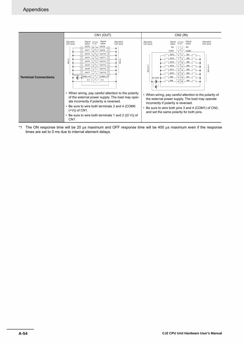
Appendices
A-54 CJ2 CPU Unit Hardware User’s Manual
*1 The ON response time will be 20 μs maximum and OFF response time will be 400 μs maximum even if the responsetimes are set to 0 ms due to internal element delays.
Terminal Connections
CN1 (OUT) CN2 (IN)
• When wiring, pay careful attention to the polarity of the external power supply. The load may oper-ate incorrectly if polarity is reversed.
• Be sure to wire both terminals 3 and 4 (COM0 (+V)) of CN1.
• Be sure to wire both terminals 1 and 2 ((0 V)) of CN1.
• When wiring, pay careful attention to the polarity of the external power supply. The load may operate incorrectly if polarity is reversed.
• Be sure to wire both pins 3 and 4 (COM1) of CN2, and set the same polarity for both pins.
1
3
5
7
9
11
13
15
OUT15
OUT14
OUT13
OUT12
OUT11
OUT10
OUT9
OUT8
17
19
COM0 (+V)
0 V 2
4
6
8
10
12
14
16
18
OUT6
OUT5
OUT4
OUT3
OUT2
OUT1
OUT0
OUT7
20
COM0 (+V)
0 V
L
L
L
L
L
L
L
L
L
L
L
L
L
L
L
L
24 VDC
Wd
m
Wd
m
AllocatedCIO word
Signalname
Signalname
AllocatedCIO word
Connec-tor pin
20
18
16
14
12
10
8
6
4
2
19
17
15
13
11
9
7 IN6
IN5
IN4
IN3
IN2
IN1
IN0
IN7 5
3
1
IN15
IN14
IN13
IN12
IN11
IN10
IN9
IN8
COM1
NC
COM1
NC
24 VDC
Wd
m+1
Wd
m+1
AllocatedCIO word
Signalname
Signalname
AllocatedCIO word
Connec-tor pin

A-55
Appendices
CJ2 CPU Unit Hardware User’s Manual
A-1 Specifications of B
asic I/O U
nitsA
ppA
-1-2 Basic I/O
Units
� CJ1W-MD563 TTL I/O Unit (32 Inputs/32 Outputs)Name 32-point Input /32-point Output TTL I/O Unit with MIL Connectors
Model CJ1W-MD563
Output section (CN1) Input section (CN2)
Rated Voltage 5 VDC±10% Rated Input Volt-age
5 VDC±10%
Operating Load Voltage Range
4.5 to 5.5 VDC Input Impedance 1.1 kΩ
Maximum Load Current 35 mA/point, 560 mA/com-mon, 1.12 A/Unit Input Current Approx. 3.5 mA (at 5 VDC)
Leakage Current 0.1 mA max. ON Voltage 3.0 VDC min.
Residual Voltage 0.4 V max. OFF Voltage 1.0 VDC max.
ON Response Time0.2 ms max. ON Response
Time8.0 ms max. (Can be set to between 0 and 32 in the PLC Setup.)*1
OFF Response Time 0.3 ms max. OFF Response Time
8.0 ms max. (Can be set to between 0 and 32 in the PLC Setup.)*1
No. of Circuits 32 points (16 points/com-mon, 2 circuits)
Fuse None No. of Circuits 32 points (16 points/common, 2 circuits)
External Power Supply5 VDC±10%, 40 mA min. (1.2 mA × No. of ON points)
Number of Simul-taneously ON Points
100% (16 points/common)
Insulation Resistance 20 MΩ between the external terminals and the GR terminal (at 100 VDC)
Dielectric Strength 1,000 VAC between the external terminals and the GR terminal for 1 minute at a leakage current of 10 mA max.
Internal Current Consump-tion
5 VDC 190 mA max.
Weight 110 g max.
Accessories None
Circuit Configuration
CN1 (OUT) CN2 (IN)
OUT0
+V
OUT15
COM0
OUT0
+V
OUT15
COM1
COM0
COM1
5.6 kΩ
5.6 kΩ
Outputindicator Indicator
switch
Inte
rnal
circ
uits
to
to
Wd m
Wd m+1
AllocatedCIO word
Signalname
IN0
IN15
COM2
IN0
IN15
COM3
COM2
COM3
to
Indicator switch
Input indicator
Inte
rnal
circ
uits
to
1.1 kΩ
2.2
kΩ
1000
pF
1.1 kΩ
2.2
kΩ
1000
pF
Wd m+2
Wd m+3
AllocatedCIO word
Signalname

Appendices
A-56 CJ2 CPU Unit Hardware User’s Manual
*1 The ON response time will be 120 μs maximum and OFF response time will be 400 μs maximum even if the responsetimes are set to 0 ms due to internal element delays.
Terminal Connections
CN1 (OUT) CN2 (IN)
• When wiring, pay careful attention to the polarity of the external power supply. The load may oper-ate incorrectly if the polarity is reversed.
• Be sure to wire both terminals 23 and 24 (COM0) of CN1.
• Be sure to wire both terminals 3 and 4 (COM1) of CN1.
• Be sure to wire both terminals 21 and 22 (+V) of CN1.
• Be sure to wire both terminals 1 and 2 (+V) of CN1.
• When wiring, pay careful attention to the polarity of the external power supply. The load may operate incorrectly if the polarity is reversed.
• Be sure to wire both pins 23 and 24 (COM2) of CN2, and set the same polarity for both pins.
• Be sure to wire both pins 3 and 4 (COM3) of CN2, and set the same polarity for both pins.
1 +V 3
5 OUT15 7 OUT14 9 OUT13
11 OUT12 13 OUT11 15 OUT10 17
19
OUT2
21
23
25
27OUT15
29OUT14
31OUT13
33OUT12
35OUT11
37
+V
39
2
4+V
6
8OUT7
10OUT6
12OUT5
14OUT4
16OUT3
18
COM1
20
22
24
26
28
30
OUT10
32
34
36
38
40
COM1
+V
OUT0
OUT7
OUT6
OUT5
OUT4
OUT3
OUT2
OUT1
COM0
OUT8
OUT9
COM0
OUT8
OUT9
OUT0
OUT1
L
L
L
L
L
L
L
L
L
L
L
L
L
L
L
L
L
L
L
L
L
L
L
L
L
L
L
L
L
L
L
L
5 VDC
5 VDC
Wd
mW
d m
+1
Wd
mW
d m
+1
AllocatedCIO word
Signalname
Signalname
AllocatedCIO word
Connec-tor pin
40 IN038 IN136 IN234 IN332 IN430 IN528 IN626 IN724
22
IN15
20
18IN0
16IN1
14IN2
12IN3
10IN4
8IN5
6IN6
4
NC2COM3
39
37IN8
35IN9
33IN10
31IN11
29IN12
27IN13
25IN14
23COM221
IN8
NC NC19
IN9 17
IN10 15
IIN11 13
IN12 11
IN7
9IN137IN145IN153
NC 1COM3
COM2
5 VDC
5 VDC
Wd
m+2
Wd
m+3
Wd
m+2
Wd
m+3
AllocatedCIO word
Signalname
Signalname
AllocatedCIO word
Connec-tor pin
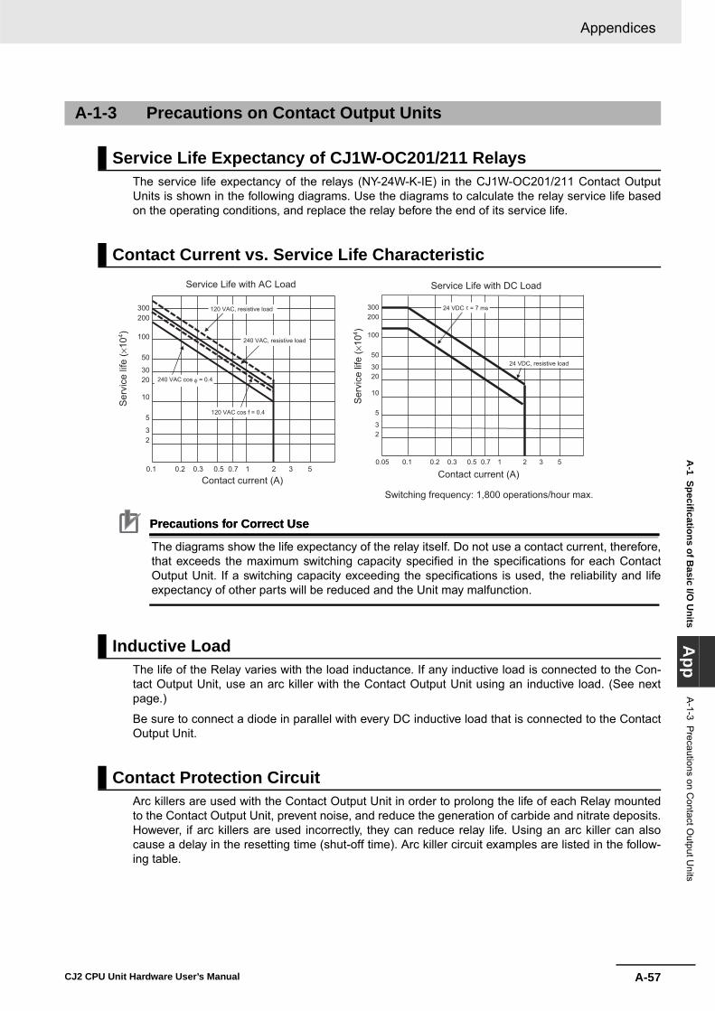
A-57
Appendices
CJ2 CPU Unit Hardware User’s Manual
A-1 Specifications of B
asic I/O U
nitsA
ppA
-1-3 Precautions on C
ontact Output U
nits
The service life expectancy of the relays (NY-24W-K-IE) in the CJ1W-OC201/211 Contact OutputUnits is shown in the following diagrams. Use the diagrams to calculate the relay service life basedon the operating conditions, and replace the relay before the end of its service life.
Precautions for Correct UsePrecautions for Correct Use
The diagrams show the life expectancy of the relay itself. Do not use a contact current, therefore,that exceeds the maximum switching capacity specified in the specifications for each ContactOutput Unit. If a switching capacity exceeding the specifications is used, the reliability and lifeexpectancy of other parts will be reduced and the Unit may malfunction.
The life of the Relay varies with the load inductance. If any inductive load is connected to the Con-tact Output Unit, use an arc killer with the Contact Output Unit using an inductive load. (See nextpage.)
Be sure to connect a diode in parallel with every DC inductive load that is connected to the ContactOutput Unit.
Arc killers are used with the Contact Output Unit in order to prolong the life of each Relay mountedto the Contact Output Unit, prevent noise, and reduce the generation of carbide and nitrate deposits.However, if arc killers are used incorrectly, they can reduce relay life. Using an arc killer can alsocause a delay in the resetting time (shut-off time). Arc killer circuit examples are listed in the follow-ing table.
A-1-3 Precautions on Contact Output Units
Service Life Expectancy of CJ1W-OC201/211 Relays
Contact Current vs. Service Life Characteristic
Inductive Load
Contact Protection Circuit
0.1 0.2 0.3 0.5 1 2 3 50.7
23
5
10
2030
50
100
200300
0.1 0.2 0.3 0.5 1 2 3 5 0.7
23
5
10
2030
50
100
200300
0.05
Service Life with AC Load Service Life with DC Load
120 VAC, resistive load
240 VAC, resistive load
120 VAC cos f = 0.4
240 VAC cos φ = 0.4
Ser
vice
life
( ×10
4 )
Ser
vice
life
( ×10
4 )
Contact current (A) Contact current (A)
24 VDC, resistive load
24 VDC τ = 7 ms
Switching frequency: 1,800 operations/hour max.

Appendices
A-58 CJ2 CPU Unit Hardware User’s Manual
Precautions for Correct UsePrecautions for Correct Use
Do not connect a capacitor as an arc killer in parallel with an inductive loadas shown in the following diagram. This arc killer is very effective for pre-venting spark discharge at the moment when the circuit is opened. How-ever, when the contacts are closed, the contacts may be welded due to thecurrent charged in the capacitor.
DC inductive loads can be more difficult to switch than resistive loads. Ifappropriate arc killers are used, however, DC inductive loads will be as easyto switch as resistive loads.
CircuitCurrent
Characteristic Required elementAC DC
CR method
Yes Yes If the load is a relay or solenoid, there is a time lag between the moment the circuit is opened and the moment the load is reset.If the supply voltage is 24 or 48 V, insert the arc killer in parallel with the load. If the supply voltage is 100 to 200 V, insert the arc killer between the contacts.
The capacitance of the capacitor must be 1 to 0.5 μF per contact current of 1 A and resistance of the resistor must be 0.5 to 1 Ω per contact volt-age of 1 V. These values, however, vary with the load and the characteristics of the relay. Decide these values from experiments, and take into con-sideration that the capacitance suppresses spark discharge when the contacts are separated and the resistance limits the current that flows into the load when the circuit is closed again.The dielectric strength of the capacitor must be 200 to 300 V. If the circuit is an AC circuit, use a capacitor with no polarity.
Diode method
No Yes The diode connected in parallel with the load changes energy accumulated by the coil into a current, which then flows into the coil so that the current will be converted into Joule heat by the resistance of the inductive load. This time lag, between the moment the cir-cuit is opened and the moment the load is reset, caused by this method is longer than that caused by the CR method.
The reversed dielectric strength value of the diode must be at least 10 times as large as the circuit voltage value. The forward current of the diode must be the same as or larger than the load current.The reversed dielectric strength value of the diode may be two to three times larger than the supply voltage if the arc killer is applied to elec-tronic circuits with low circuit voltages.
Varistor method
Yes Yes The varistor method prevents the imposition of high voltage between the contacts by using the constant voltage characteristic of the varistor. There is time lag between the moment the cir-cuit is opened and the moment the load is reset.If the supply voltage is 24 or 48 V, insert the varistor in parallel with the load. If the supply voltage is 100 to 200 V, insert the varistor between the contacts.
---
Powersupply
Indu
ctiv
e lo
adC
R
Powersupply
Indu
ctiv
e lo
ad
Powersupply
Indu
ctiv
e lo
ad
CPowersupply
Indu
ctiv
e lo
ad
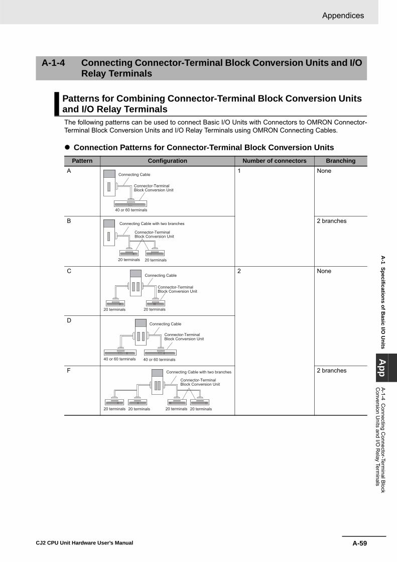
A-59
Appendices
CJ2 CPU Unit Hardware User’s Manual
A-1 Specifications of B
asic I/O U
nitsA
ppA
-1-4 Connecting C
onnector-Terminal B
lock C
onversion Units and I/O
Relay Term
inals
The following patterns can be used to connect Basic I/O Units with Connectors to OMRON Connector-Terminal Block Conversion Units and I/O Relay Terminals using OMRON Connecting Cables.
� Connection Patterns for Connector-Terminal Block Conversion Units
A-1-4 Connecting Connector-Terminal Block Conversion Units and I/O Relay Terminals
Patterns for Combining Connector-Terminal Block Conversion Units and I/O Relay Terminals
Pattern Configuration Number of connectors BranchingA 1 None
B 2 branches
C 2 None
D
F 2 branches
Connecting Cable
Connector-TerminalBlock Conversion Unit
40 or 60 terminals
Connecting Cable with two branches
Connector-TerminalBlock Conversion Unit
20 terminals 20 terminals
Connecting Cable
Connector-TerminalBlock Conversion Unit
20 terminals 20 terminals
Connecting Cable
Connector-TerminalBlock Conversion Unit
40 or 60 terminals 40 or 60 terminals
Connecting Cable with two branches
Connector-TerminalBlock Conversion Unit
20 terminals 20 terminals 20 terminals 20 terminals
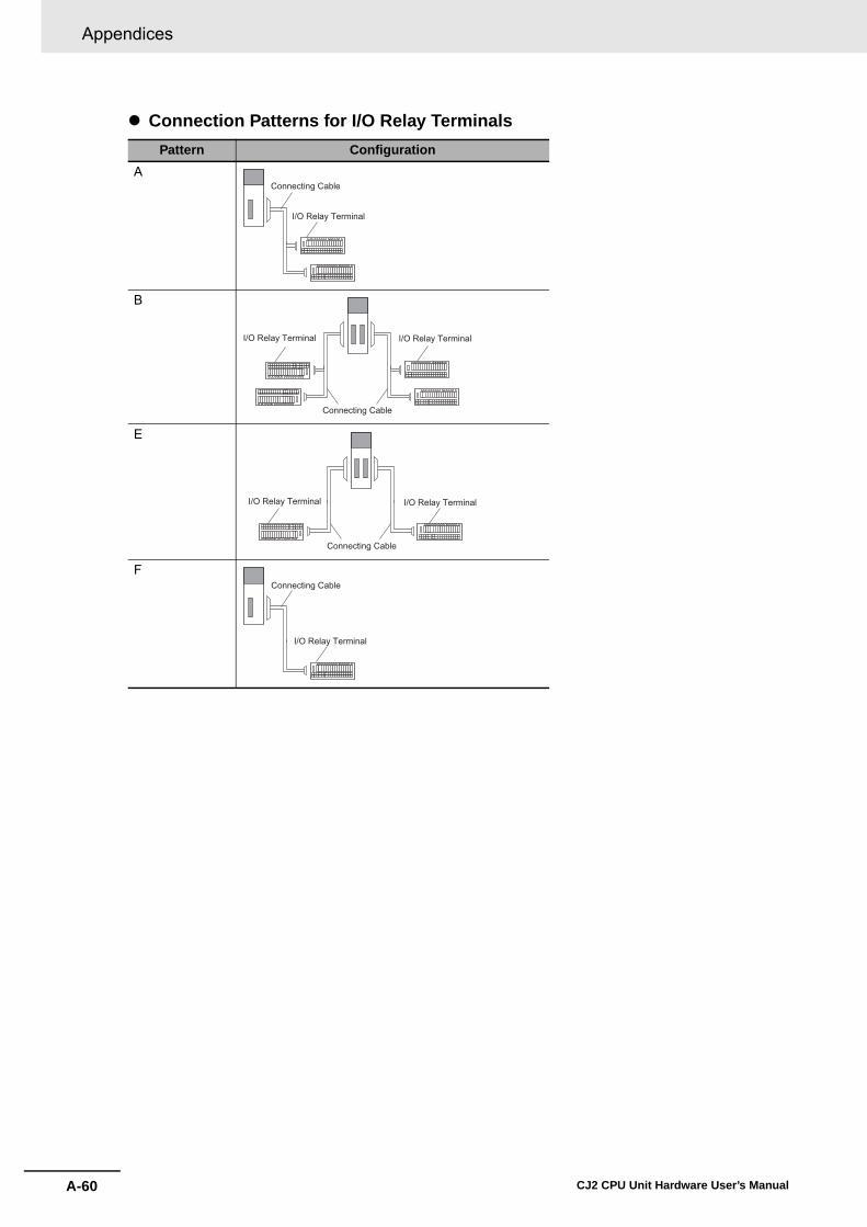
Appendices
A-60 CJ2 CPU Unit Hardware User’s Manual
� Connection Patterns for I/O Relay TerminalsPattern Configuration
A
B
E
F
Connecting Cable
I/O Relay Terminal
Connecting Cable
I/O Relay Terminal I/O Relay Terminal
Connecting Cable
I/O Relay Terminal I/O Relay Terminal
Connecting Cable
I/O Relay Terminal
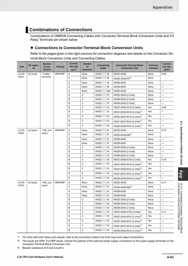
A-61
Appendices
CJ2 CPU Unit Hardware User’s Manual
A-1 Specifications of B
asic I/O U
nitsA
ppA
-1-4 Connecting C
onnector-Terminal B
lock C
onversion Units and I/O
Relay Term
inals
Combinations of OMRON Connecting Cables with Connector-Terminal Block Conversion Units and I/ORelay Terminals are shown below.
� Connections to Connector-Terminal Block Conversion UnitsRefer to the pages given in the right columns for connection diagrams and details on the Connector-Ter-minal Block Conversion Units and Connecting Cables.
*1 For Units with both inputs and outputs, refer to the connection patterns for both input and output connections.*2 The inputs are NPN. For PNP inputs, reverse the polarity of the external power supply connections to the power supply terminals on the
Connector-Terminal Block Conversion Unit.*3 Bleeder resistance (5.6 kΩ) is built in.
Combinations of Connections
Unit I/O capac-ity
Number of con-nectors
PolarityConnec-tion pat-
tern*1
Number of
branches
Connecting Cable
Connector-Terminal Block Conversion Unit
Common terminal
Connec-tion dia-
gram
CJ1W-ID231
32 inputs 1 Fujitsu connector
NPN/PNP A None XW2Z-@@@B XW2D-40G6 None A-69
A None XW2Z-@@@B XW2D-40G6-RF*3 None
A None XW2Z-@@@B XW2B-40G5 None ---
A None XW2Z-@@@B XW2B-40G4 None ---
A None XW2Z-@@@BU XW2D-40C6 None ---
B 2 XW2Z-@@@D XW2D-20G6 (2 Units) None ---
B 2 XW2Z-@@@D XW2B-20G5 (2 Units) None ---
B 2 XW2Z-@@@D XW2B-20G4 (2 Units) None ---
B 2 XW2Z-@@@D XW2C-20G6-IO16 (2 Units) Yes A-69
B 2 XW2Z-@@@D XW2C-20G5-IN16 (2 Units)*2 Yes ---
B 2 XW2Z-@@@D XW2E-20G5-IN16 (2 Units)*2 Yes ---
B 2 XW2Z-@@@D XW2F-20G7-IN16 (2 Units)*2 Yes ---
B 2 XW2Z-@@@D XW2N-20G8-IN16 (2 Units)*2 Yes ---
CJ1W-ID232
32 inputs 1 MIL con-nector
NPN/PNP A None XW2Z-@@@K XW2D-40G6 None A-70
A None XW2Z-@@@K XW2D-40G6-RM*3 None
A None XW2Z-@@@K XW2B-40G5 None ---
A None XW2Z-@@@K XW2B-40G4 None ---
B 2 XW2Z-@@@N XW2D-20G6 (2 Units) None ---
B 2 XW2Z-@@@N XW2B-20G5 (2 Units) None ---
B 2 XW2Z-@@@N XW2B-20G4 (2 Units) None ---
B 2 XW2Z-@@@N XW2C-20G6-IO16 (2 Units) Yes A-70
B 2 XW2Z-@@@N XW2C-20G5-IN16 (2 Units)*2 Yes ---
B 2 XW2Z-@@@N XW2E-20G5-IN16 (2 Units)*2 Yes ---
B 2 XW2Z-@@@N XW2F-20G7-IN16 (2 Units)*2 Yes ---
B 2 XW2Z-@@@N XW2N-20G8-IN16 (2 Units)*2 Yes ---
CJ1W-ID233
32 inputs 1 MIL con-nector
NPN/PNP A None XW2Z-@@@K XW2D-40G6 None A-71
A None XW2Z-@@@K XW2D-40G6-RM*3 None
A None XW2Z-@@@K XW2B-40G5 None ---
A None XW2Z-@@@K XW2B-40G4 None ---
B 2 XW2Z-@@@N XW2D-20G6 (2 Units) None ---
B 2 XW2Z-@@@N XW2B-20G5 (2 Units) None ---
B 2 XW2Z-@@@N XW2B-20G4 (2 Units) None ---
B 2 XW2Z-@@@N XW2C-20G6-IO16 (2 Units) Yes A-71
B 2 XW2Z-@@@N XW2C-20G5-IN16 (2 Units)*2 Yes ---
B 2 XW2Z-@@@N XW2E-20G5-IN16 (2 Units)*2 Yes ---
B 2 XW2Z-@@@N XW2F-20G7-IN16 (2 Units)*2 Yes ---
B 2 XW2Z-@@@N XW2N-20G8-IN16 (2 Units)*2 Yes ---

Appendices
A-62 CJ2 CPU Unit Hardware User’s Manual
*1 For Units with both inputs and outputs, refer to the connection patterns for both input and output connections.*2 The inputs are NPN. For PNP inputs, reverse the polarity of the external power supply connections to the power supply
terminals on the Connector-Terminal Block Conversion Unit.*3 Bleeder resistance (5.6 kΩ) is built in.
Unit I/O capac-ity
Number of con-nectors
PolarityConnec-tion pat-
tern*1
Number of
branches
Connecting Cable
Connector-Terminal Block Conversion Unit
Common terminal
Connec-tion dia-
gram
CJ1W-ID261
64 inputs 2 Fujitsu connectors
NPN/PNP D None XW2Z-@@@B XW2D-40G6 None A-72
D None XW2Z-@@@B XW2D-40G6-RF*3 None
D None XW2Z-@@@B XW2B-40G5 None ---
D None XW2Z-@@@B XW2B-40G4 None ---
D None XW2Z-@@@BU XW2D-40C6 None ---
F 2 XW2Z-@@@D XW2D-20G6 (2 Units) None ---
F 2 XW2Z-@@@D XW2B-20G5 (2 Units) None ---
F 2 XW2Z-@@@D XW2B-20G4 (2 Units) None ---
F 2 XW2Z-@@@D XW2C-20G6-IO16 (2 Units) Yes A-72
F 2 XW2Z-@@@D XW2C-20G5-IN16 (2 Units)*2 Yes ---
F 2 XW2Z-@@@D XW2E-20G5-IN16 (2 Units)*2 Yes ---
F 2 XW2Z-@@@D XW2F-20G7-IN16 (2 Units)*2 Yes ---
F 2 XW2Z-@@@D XW2N-20G8-IN16 (2 Units)*2 Yes ---
CJ1W-ID262
64 inputs 2 MIL con-nectors
NPN/PNP D None XW2Z-@@@K XW2D-40G6 None A-73
D None XW2Z-@@@K XW2D-40G6-RM*3 None
D None XW2Z-@@@K XW2B-40G5 None ---
D None XW2Z-@@@K XW2B-40G4 None ---
F 2 XW2Z-@@@N XW2D-20G6 (2 Units) None ---
F 2 XW2Z-@@@N XW2B-20G5 (2 Units) None ---
F 2 XW2Z-@@@N XW2B-20G4 (2 Units) None ---
F 2 XW2Z-@@@N XW2C-20G6-IO16 (2 Units) Yes A-73
F 2 XW2Z-@@@N XW2C-20G5-IN16 (2 Units)*2 Yes ---
F 2 XW2Z-@@@N XW2E-20G5-IN16 (2 Units)*2 Yes ---
F 2 XW2Z-@@@N XW2F-20G7-IN16 (2 Units)*2 Yes ---
F 2 XW2Z-@@@N XW2N-20G8-IN16 (2 Units)*2 Yes ---
CJ1W-OD231
32 outputs 1 Fujitsu connector
NPN A None XW2Z-@@@B XW2D-40G6 None A-74
A None XW2Z-@@@B XW2B-40G5 None ---
A None XW2Z-@@@B XW2B-40G4 None ---
A None XW2Z-@@@BU XW2D-40C6 None A-74
B 2 XW2Z-@@@L XW2D-20G6 (2 Units) None ---
B 2 XW2Z-@@@L XW2B-20G5 (2 Units) None ---
B 2 XW2Z-@@@L XW2B-20G4 (2 Units) None ---
B 2 XW2Z-@@@L XW2C-20G6-IO16 (2 Units) Yes A-74
B 2 XW2Z-@@@L XW2F-20G7-OUT16 (2 Units) Yes ---
CJ1W-OD232
32 outputs 1 MIL con-nector
PNP A None XW2Z-@@@K XW2D-40G6 None A-75
A None XW2Z-@@@K XW2B-40G5 None ---
A None XW2Z-@@@K XW2B-40G4 None ---
B 2 XW2Z-@@@N XW2D-20G6 (2 Units) None ---
B 2 XW2Z-@@@N XW2B-20G5 (2 Units) None ---
B 2 XW2Z-@@@N XW2B-20G4 (2 Units) None ---
B 2 XW2Z-@@@N XW2C-20G6-IO16 (2 Units) Yes A-75
B 2 XW2Z-@@@N XW2F-20G7-OUT16 (2 Units) Yes ---
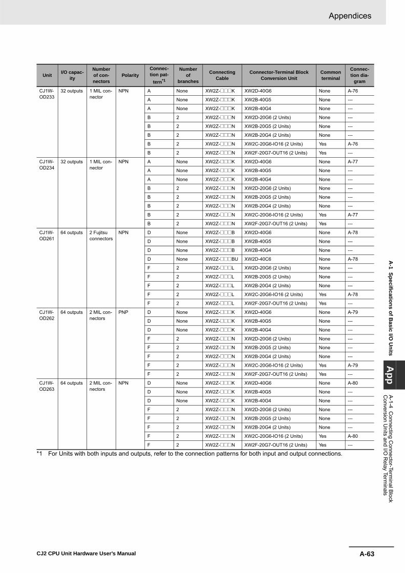
A-63
Appendices
CJ2 CPU Unit Hardware User’s Manual
A-1 Specifications of B
asic I/O U
nitsA
ppA
-1-4 Connecting C
onnector-Terminal B
lock C
onversion Units and I/O
Relay Term
inals
*1 For Units with both inputs and outputs, refer to the connection patterns for both input and output connections.
Unit I/O capac-ity
Number of con-nectors
PolarityConnec-tion pat-
tern*1
Number of
branches
Connecting Cable
Connector-Terminal Block Conversion Unit
Common terminal
Connec-tion dia-
gram
CJ1W-OD233
32 outputs 1 MIL con-nector
NPN A None XW2Z-@@@K XW2D-40G6 None A-76
A None XW2Z-@@@K XW2B-40G5 None ---
A None XW2Z-@@@K XW2B-40G4 None ---
B 2 XW2Z-@@@N XW2D-20G6 (2 Units) None ---
B 2 XW2Z-@@@N XW2B-20G5 (2 Units) None ---
B 2 XW2Z-@@@N XW2B-20G4 (2 Units) None ---
B 2 XW2Z-@@@N XW2C-20G6-IO16 (2 Units) Yes A-76
B 2 XW2Z-@@@N XW2F-20G7-OUT16 (2 Units) Yes ---
CJ1W-OD234
32 outputs 1 MIL con-nector
NPN A None XW2Z-@@@K XW2D-40G6 None A-77
A None XW2Z-@@@K XW2B-40G5 None ---
A None XW2Z-@@@K XW2B-40G4 None ---
B 2 XW2Z-@@@N XW2D-20G6 (2 Units) None ---
B 2 XW2Z-@@@N XW2B-20G5 (2 Units) None ---
B 2 XW2Z-@@@N XW2B-20G4 (2 Units) None ---
B 2 XW2Z-@@@N XW2C-20G6-IO16 (2 Units) Yes A-77
B 2 XW2Z-@@@N XW2F-20G7-OUT16 (2 Units) Yes ---
CJ1W-OD261
64 outputs 2 Fujitsu connectors
NPN D None XW2Z-@@@B XW2D-40G6 None A-78
D None XW2Z-@@@B XW2B-40G5 None ---
D None XW2Z-@@@B XW2B-40G4 None ---
D None XW2Z-@@@BU XW2D-40C6 None A-78
F 2 XW2Z-@@@L XW2D-20G6 (2 Units) None ---
F 2 XW2Z-@@@L XW2B-20G5 (2 Units) None ---
F 2 XW2Z-@@@L XW2B-20G4 (2 Units) None ---
F 2 XW2Z-@@@L XW2C-20G6-IO16 (2 Units) Yes A-78
F 2 XW2Z-@@@L XW2F-20G7-OUT16 (2 Units) Yes ---
CJ1W-OD262
64 outputs 2 MIL con-nectors
PNP D None XW2Z-@@@K XW2D-40G6 None A-79
D None XW2Z-@@@K XW2B-40G5 None ---
D None XW2Z-@@@K XW2B-40G4 None ---
F 2 XW2Z-@@@N XW2D-20G6 (2 Units) None ---
F 2 XW2Z-@@@N XW2B-20G5 (2 Units) None ---
F 2 XW2Z-@@@N XW2B-20G4 (2 Units) None ---
F 2 XW2Z-@@@N XW2C-20G6-IO16 (2 Units) Yes A-79
F 2 XW2Z-@@@N XW2F-20G7-OUT16 (2 Units) Yes ---
CJ1W-OD263
64 outputs 2 MIL con-nectors
NPN D None XW2Z-@@@K XW2D-40G6 None A-80
D None XW2Z-@@@K XW2B-40G5 None ---
D None XW2Z-@@@K XW2B-40G4 None ---
F 2 XW2Z-@@@N XW2D-20G6 (2 Units) None ---
F 2 XW2Z-@@@N XW2B-20G5 (2 Units) None ---
F 2 XW2Z-@@@N XW2B-20G4 (2 Units) None ---
F 2 XW2Z-@@@N XW2C-20G6-IO16 (2 Units) Yes A-80
F 2 XW2Z-@@@N XW2F-20G7-OUT16 (2 Units) Yes ---

Appendices
A-64 CJ2 CPU Unit Hardware User’s Manual
*1 For Units with both inputs and outputs, refer to the connection patterns for both input and output connections.*2 The inputs are NPN. For PNP inputs, reverse the polarity of the external power supply connections to the power supply terminals on the
Connector-Terminal Block Conversion Unit.*3 Bleeder resistance (5.6 kΩ) is built in.
Unit I/O capac-ity
Number of con-nectors
PolarityConnec-tion pat-
tern*1
Number of
branches
Connecting Cable
Connector-Terminal Block Conversion Unit
Common terminal
Connec-tion dia-
gram
CJ1W-MD231
16 inputs 1 Fujitsu connector
NPN/PNP C None XW2Z-@@@A XW2D-20G6 None A-81
C None XW2Z-@@@A XW2B-20G5 None ---
C None XW2Z-@@@A XW2B-20G4 None ---
C None XW2Z-@@@A XW2C-20G6-IO16 Yes A-82
C None XW2Z-@@@A XW2C-20G5-IN16*2 Yes ---
C None XW2Z-@@@A XW2E-20G5-IN16*2 Yes ---
C None XW2Z-@@@A XW2F-20G7-IN16*2 Yes ---
C None XW2Z-@@@A XW2N-20G8-IN16*2 Yes ---
16 outputs 1 Fujitsu connector
NPN C None XW2Z-@@@A XW2D-20G6 None A-81
C None XW2Z-@@@A XW2B-20G5 None ---
C None XW2Z-@@@A XW2B-20G4 None ---
C None XW2Z-@@@A XW2C-20G6-IO16 Yes A-82
C None XW2Z-@@@A XW2F-20G7-OUT16 Yes ---
CJ1W-MD232
16 inputs 1 MIL con-nector
NPN/PNP C None XW2Z-@@@X XW2D-20G6 None A-83
C None XW2Z-@@@X XW2B-20G5 None ---
C None XW2Z-@@@X XW2B-20G4 None ---
16 outputs 1 MIL con-nector
PNP C None XW2Z-@@@X XW2D-20G6 None A-83
C None XW2Z-@@@X XW2B-20G5 None ---
C None XW2Z-@@@X XW2B-20G4 None ---
CJ1W-MD233
16 inputs 1 MIL con-nector
NPN/PNP C None XW2Z-@@@X XW2D-20G6 None A-83
C None XW2Z-@@@X XW2B-20G5 None ---
C None XW2Z-@@@X XW2B-20G4 None ---
16 outputs 1 MIL con-nector
NPN C None XW2Z-@@@X XW2D-20G6 None A-83
C None XW2Z-@@@X XW2B-20G5 None ---
C None XW2Z-@@@X XW2B-20G4 None ---
CJ1W-MD261
32 outputs 1 Fujitsu connector
NPN/PNP D None XW2Z-@@@B XW2D-40G6 None A-84
D None XW2Z-@@@B XW2D-40G6-RF*3 None
D None XW2Z-@@@B XW2B-40G5 None ---
D None XW2Z-@@@B XW2B-40G4 None ---
D None XW2Z-@@@BU XW2D-40C6 None ---
F 2 XW2Z-@@@D XW2D-20G6 (2 Units) None ---
F 2 XW2Z-@@@D XW2B-20G5 (2 Units) None ---
F 2 XW2Z-@@@D XW2B-20G4 (2 Units) None ---
F 2 XW2Z-@@@D XW2C-20G6-IO16 (2 Units) Yes A-85
F 2 XW2Z-@@@D XW2C-20G5-IN16 (2 Units)*2 Yes ---
F 2 XW2Z-@@@D XW2E-20G5-IN16 (2 Units)*2 Yes ---
F 2 XW2Z-@@@D XW2F-20G7-IN16 (2 Units)*2 Yes ---
F 2 XW2Z-@@@D XW2N-20G8-IN16 (2 Units)*2 Yes ---
32 outputs 1 Fujitsu connector
NPN D None XW2Z-@@@B XW2D-40G6 None A-84
D None XW2Z-@@@B XW2B-40G5 None ---
D None XW2Z-@@@B XW2B-40G4 None ---
D None XW2Z-@@@BU XW2D-40C6 None ---
F 2 XW2Z-@@@L XW2D-20G6 (2 Units) None ---
F 2 XW2Z-@@@L XW2B-20G5 (2 Units) None ---
F 2 XW2Z-@@@L XW2B-20G4 (2 Units) None ---
F 2 XW2Z-@@@L XW2C-20G6-IO16 (2 Units) Yes A-85
F 2 XW2Z-@@@L XW2F-20G7-OUT16 (2 Units) Yes ---

A-65
Appendices
CJ2 CPU Unit Hardware User’s Manual
A-1 Specifications of B
asic I/O U
nitsA
ppA
-1-4 Connecting C
onnector-Terminal B
lock C
onversion Units and I/O
Relay Term
inals
*1 For Units with both inputs and outputs, refer to the connection patterns for both input and output connections.*2 The inputs are NPN. For PNP inputs, reverse the polarity of the external power supply connections to the power supply terminals on the
Connector-Terminal Block Conversion Unit.*3 Bleeder resistance (5.6 kΩ) is built in.
Unit I/O capac-ity
Number of con-nectors
PolarityConnec-tion pat-
tern*1
Number of
branches
Connecting Cable
Connector-Terminal Block Conversion Unit
Common terminal
Connec-tion dia-
gram
CJ1W-MD263
32 inputs 1 MIL con-nector
NPN/PNP D None XW2Z-@@@K XW2D-40G6 None A-86
D None XW2Z-@@@K XW2D-40G6-RM*3 None
D None XW2Z-@@@K XW2B-40G5 None ---
D None XW2Z-@@@K XW2B-40G4 None ---
F 2 XW2Z-@@@N XW2D-20G6 (2 Units) None ---
F 2 XW2Z-@@@N XW2B-20G5 (2 Units) None ---
F 2 XW2Z-@@@N XW2B-20G4 (2 Units) None ---
F 2 XW2Z-@@@N XW2C-20G6-IO16 (2 Units) None A-87
F 2 XW2Z-@@@N XW2C-20G5-IN16 (2 Units)*2 Yes ---
F 2 XW2Z-@@@N XW2E-20G5-IN16 (2 Units)*2 Yes ---
F 2 XW2Z-@@@N XW2F-20G7-IN16 (2 Units)*2 Yes ---
F 2 XW2Z-@@@N XW2N-20G8-IN16 (2 Units)*2 Yes ---
32 outputs 1 MIL con-nector
NPN D None XW2Z-@@@B XW2D-40G6 None A-86
D None XW2Z-@@@B XW2B-40G5 None ---
D None XW2Z-@@@B XW2B-40G4 None ---
F 2 XW2Z-@@@L XW2D-20G6 (2 Units) None ---
F 2 XW2Z-@@@L XW2B-20G5 (2 Units) None ---
F 2 XW2Z-@@@L XW2B-20G4 (2 Units) None ---
F 2 XW2Z-@@@L XW2C-20G6-IO16 (2 Units) Yes A-87
F 2 XW2Z-@@@L XW2F-20G7-OUT16 (2 Units) Yes ---
CJ1W-MD563
32 inputs 1 MIL con-nector
NPN/PNP D None XW2Z-@@@K XW2D-40G6 None A-88
D None XW2Z-@@@K XW2D-40G6-RM*3 None
D None XW2Z-@@@K XW2B-40G5 None ---
D None XW2Z-@@@K XW2B-40G4 None ---
F 2 XW2Z-@@@N XW2D-20G6 (2 Units) None ---
F 2 XW2Z-@@@N XW2B-20G5 (2 Units) None ---
F 2 XW2Z-@@@N XW2B-20G4 (2 Units) None ---
32 outputs 1 MIL con-nector
NPN D None XW2Z-@@@K XW2D-40G6 None A-88
D None XW2Z-@@@K XW2B-40G5 None ---
D None XW2Z-@@@K XW2B-40G4 None ---
F 2 XW2Z-@@@N XW2D-20G6 (2 Units) None ---
F 2 XW2Z-@@@N XW2B-20G5 (2 Units) None ---
F 2 XW2Z-@@@N XW2B-20G4 (2 Units) None ---
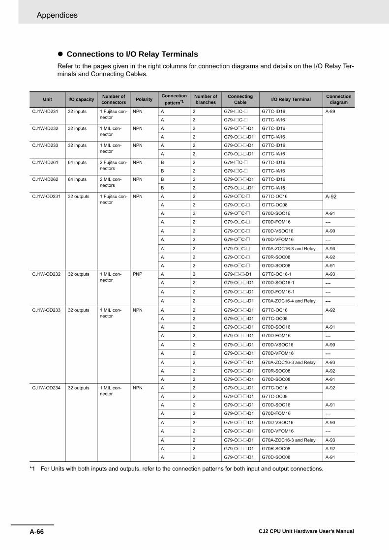
Appendices
A-66 CJ2 CPU Unit Hardware User’s Manual
� Connections to I/O Relay TerminalsRefer to the pages given in the right columns for connection diagrams and details on the I/O Relay Ter-minals and Connecting Cables.
*1 For Units with both inputs and outputs, refer to the connection patterns for both input and output connections.
Unit I/O capacity Number of connectors Polarity
Connection pattern*1
Number of branches
ConnectingCable I/O Relay Terminal Connection
diagram
CJ1W-ID231 32 inputs 1 Fujitsu con-nector
NPN A 2 G79-I@C-@ G7TC-ID16 A-89
A 2 G79-I@C-@ G7TC-IA16
CJ1W-ID232 32 inputs 1 MIL con-nector
NPN A 2 G79-O@-@-D1 G7TC-ID16
A 2 G79-O@-@-D1 G7TC-IA16
CJ1W-ID233 32 inputs 1 MIL con-nector
NPN A 2 G79-O@-@-D1 G7TC-ID16
A 2 G79-O@-@-D1 G7TC-IA16
CJ1W-ID261 64 inputs 2 Fujitsu con-nectors
NPN B 2 G79-I@C-@ G7TC-ID16
B 2 G79-I@C-@ G7TC-IA16
CJ1W-ID262 64 inputs 2 MIL con-nectors
NPN B 2 G79-O@-@-D1 G7TC-ID16
B 2 G79-O@-@-D1 G7TC-IA16
CJ1W-OD231 32 outputs 1 Fujitsu con-nector
NPN A 2 G79-O@C-@ G7TC-OC16 A-92A 2 G79-O@C-@ G7TC-OC08
A 2 G79-O@C-@ G70D-SOC16 A-91
A 2 G79-O@C-@ G70D-FOM16 ---
A 2 G79-O@C-@ G70D-VSOC16 A-90
A 2 G79-O@C-@ G70D-VFOM16 ---
A 2 G79-O@C-@ G70A-ZOC16-3 and Relay A-93
A 2 G79-O@C-@ G70R-SOC08 A-92
A 2 G79-O@C-@ G70D-SOC08 A-91
CJ1W-OD232 32 outputs 1 MIL con-nector
PNP A 2 G79-I@-@-D1 G7TC-OC16-1 A-93
A 2 G79-O@-@-D1 G70D-SOC16-1 ---
A 2 G79-O@-@-D1 G70D-FOM16-1 ---
A 2 G79-O@-@-D1 G70A-ZOC16-4 and Relay ---
CJ1W-OD233 32 outputs 1 MIL con-nector
NPN A 2 G79-O@-@-D1 G7TC-OC16 A-92
A 2 G79-O@-@-D1 G7TC-OC08
A 2 G79-O@-@-D1 G70D-SOC16 A-91
A 2 G79-O@-@-D1 G70D-FOM16 ---
A 2 G79-O@-@-D1 G70D-VSOC16 A-90
A 2 G79-O@-@-D1 G70D-VFOM16 ---
A 2 G79-O@-@-D1 G70A-ZOC16-3 and Relay A-93
A 2 G79-O@-@-D1 G70R-SOC08 A-92
A 2 G79-O@-@-D1 G70D-SOC08 A-91
CJ1W-OD234 32 outputs 1 MIL con-nector
NPN A 2 G79-O@-@-D1 G7TC-OC16 A-92
A 2 G79-O@-@-D1 G7TC-OC08
A 2 G79-O@-@-D1 G70D-SOC16 A-91
A 2 G79-O@-@-D1 G70D-FOM16 ---
A 2 G79-O@-@-D1 G70D-VSOC16 A-90
A 2 G79-O@-@-D1 G70D-VFOM16 ---
A 2 G79-O@-@-D1 G70A-ZOC16-3 and Relay A-93
A 2 G79-O@-@-D1 G70R-SOC08 A-92
A 2 G79-O@-@-D1 G70D-SOC08 A-91

A-67
Appendices
CJ2 CPU Unit Hardware User’s Manual
A-1 Specifications of B
asic I/O U
nitsA
ppA
-1-4 Connecting C
onnector-Terminal B
lock C
onversion Units and I/O
Relay Term
inals
*1 For Units with both inputs and outputs, refer to the connection patterns for both input and output connections.
Unit I/O capacity Number of connectors Polarity
Connectionpattern*1
Number of branches
Connecting Cable I/O Relay Terminal Connection
diagram
CJ1W-OD261 64 outputs 2 Fujitsu con-nectors
NPN B 2 G79-O@C-@ G7TC-OC16 A-92
B 2 G79-O@C-@ G7TC-OC08
B 2 G79-O@C-@ G70D-SOC16 A-91
B 2 G79-O@C-@ G70D-FOM16 ---
B 2 G79-O@C-@ G70D-VSOC16 A-90
B 2 G79-O@C-@ G70D-VFOM16 ---
B 2 G79-O@C-@ G70A-ZOC16-3 and Relay A-93
B 2 G79-O@C-@ G70R-SOC08 A-92
B 2 G79-O@C-@ G70D-SOC08 A-91
CJ1W-OD262 64 outputs 2 MIL con-nectors
PNP B 2 G79-I@-@-D1 G7TC-OC16-1 A-93
B 2 G79-O@-@-D1 G70D-SOC16-1 ---
B 2 G79-O@-@-D1 G70D-FOM16-1 ---
B 2 G79-O@-@-D1 G70A-ZOC16-4 and Relay ---
CJ1W-OD263 64 outputs 2 MIL con-nectors
NPN B 2 G79-O@-@-D1 G7TC-OC16 A-92
B 2 G79-O@-@-D1 G7TC-OC08
B 2 G79-O@-@-D1 G70D-SOC16 A-91
B 2 G79-O@-@-D1 G70D-FOM16 ---
B 2 G79-O@-@-D1 G70D-VSOC16 A-90
B 2 G79-O@-@-D1 G70D-VFOM16 ---
B 2 G79-O@-@-D1 G70A-ZOC16-3 and Relay A-93
B 2 G79-O@-@-D1 G70R-SOC08 A-92
B 2 G79-O@-@-D1 G70D-SOC08 A-91
CJ1W-MD231 16 inputs 1 Fujitsu con-nector
NPN F None G79-@C G7TC-ID16 A-89
F None G79-@C G7TC-IA16
16 outputs 1 Fujitsu con-nector
NPN F None G79-@C G7TC-OC16 A-92
F None G79-@C G7TC-OC08
F None G79-@C G70D-SOC16 A-91
F None G79-@C G70D-FOM16 ---
F None G79-@C G70D-VSOC16 A-90
F None G79-@C G70D-VFOM16 ---
F None G79-@C G70A-ZOC16-3 and Relay A-93
F None G79-@C G70R-SOC08 A-92
F None G79-@C G70D-SOC08 A-91
CJ1W-MD232 16 outputs 1 MIL con-nector
PNP F None G79-O@C G7TC-OC16-1 A-93
F None G79-I@C G70D-SOC16-1 ---
F None G79-I@C G70D-FOM16-1 ---
F None G79-I@C G70A-ZOC16-4 and Relay ---
CJ1W-MD233 16 inputs 1 MIL con-nector
NPN E None G79-O@C G7TC-ID16 A-89
E None G79-O@C G7TC-IA16
16 outputs 1 MIL con-nector
NPN E None G79-O@C G7TC-OC16 A-92
E None G79-O@C G7TC-OC08
E None G79-O@C G70D-SOC16 A-91
E None G79-O@C G70D-FOM16 ---
E None G79-O@C G70D-VSOC16 A-90
E None G79-O@C G70D-VFOM16 ---
E None G79-O@C G70A-ZOC16-3 and Relay A-93
E None G79-O@C G70R-SOC08 A-92
E None G79-O@C G70D-SOC08 A-91
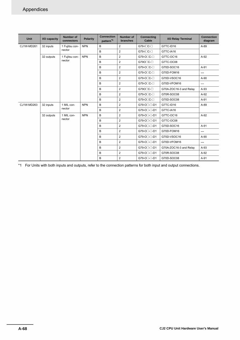
Appendices
A-68 CJ2 CPU Unit Hardware User’s Manual
*1 For Units with both inputs and outputs, refer to the connection patterns for both input and output connections.
Unit I/O capacity Number of connectors Polarity
Connection pattern*1
Number of branches
ConnectingCable I/O Relay Terminal Connection
diagram
CJ1W-MD261 32 inputs 1 Fujitsu con-nector
NPN B 2 G79-I@C-@ G7TC-ID16 A-89
B 2 G79-I@C-@ G7TC-IA16
32 outputs 1 Fujitsu con-nector
NPN B 2 G79-O@C-@ G7TC-OC16 A-92
B 2 G79O@C-@ G7TC-OC08
B 2 G79-O@C-@ G70D-SOC16 A-91
B 2 G79-O@C-@ G70D-FOM16 ---
B 2 G79-O@C-@ G70D-VSOC16 A-90
B 2 G79-O@C-@ G70D-VFOM16 ---
B 2 G79O@C-@ G70A-ZOC16-3 and Relay A-93
B 2 G79-O@C-@ G70R-SOC08 A-92
B 2 G79-O@C-@ G70D-SOC08 A-91
CJ1W-MD263 32 inputs 1 MIL con-nector
NPN B 2 G79-O@-@-D1 G7TC-ID16 A-89
B 2 G79-O@-@-D1 G7TC-IA16
32 outputs 1 MIL con-nector
NPN B 2 G79-O@-@-D1 G7TC-OC16 A-92
B 2 G79-O@-@-D1 G7TC-OC08
B 2 G79-O@-@-D1 G70D-SOC16 A-91
B 2 G79-O@-@-D1 G70D-FOM16 ---
B 2 G79-O@-@-D1 G70D-VSOC16 A-90
B 2 G79-O@-@-D1 G70D-VFOM16 ---
B 2 G79-O@-@-D1 G70A-ZOC16-3 and Relay A-93
B 2 G79-O@-@-D1 G70R-SOC08 A-92
B 2 G79-O@-@-D1 G70D-SOC08 A-91

A-69
Appendices
CJ2 CPU Unit Hardware User’s Manual
A-1 Specifications of B
asic I/O U
nitsA
ppA
-1-4 Connecting C
onnector-Terminal B
lock C
onversion Units and I/O
Relay Term
inals
The applicable terminals on the Connector-Terminal Block Conversion Unit and external connectiondiagrams are provided below for Basic I/O Unit connections to Connector-Terminal Block ConversionUnits.
� Inputs
Note 1 The polarity for input power supply connectionsindicated with dotted lines ( ) can be con-nected in either direction provided that the samepolarity is used for the commons for rows A and B.
2 Both COM0 and COM1 have two pins each. Theyare internally connected inside the PLC, but theymust all be wired.
Note 1 Connect the A9/B9 terminal and the terminal forNPN.Connect the A9/B9 terminal and the terminal forPNP. (Use the enclosed short bar.)
2 The COM terminals are wired inside the Connec-tor-Terminal Block Conversion Unit.
Connector-Terminal Block Conversion Unit Connection Diagrams
Programma-ble Control-ler I/O Unit
CJ1W-ID231
Connector-Terminal Block Con-version Unit
XW2D-40G6XW2D-40G6-RF
Connecting Cables
XW2Z-@@@B
Connection diagram
Wd m
A20
A11
A12
A13
A14
A15
A16
A17
A18
A19
B20
B11
B12
B13
B14
B15
B16
B17
B18
B19
A10
A1
A2
A3
A4
A5
A6
A7
A8
A9
B10
B1
B2
B3
B4
B5
B6
B7
B8
B9
15
COM0
NC
14
13
12
11
10
09
08
NC
07
COM0
06
05
04
03
02
01
00
15
COM1
NC
14
13
12
11
10
09
08
NC
07
COM1
06
05
04
03
02
01
00
Wd (m+1)
24VDC
24VDC
Programma-ble Controller I/O Unit
CJ1W-ID231
Connector-Ter-minal Block Conversion Unit
XW2C-20G6-IO16 (two Units)
Connecting Cables
XW2Z-@@@D
Connection diagram
0
1
2
3
4
5
6
7
8
9
10
11
12
13
14
15
A9B9
A10B10
24 VDC
(Short bar)
Wd m(Wd (m+1))
PNP
NPN
Black (White)Brown (Red)Blue (Black)
Blue (Black)Brown (White)
Black (White)
Brown (Red)
Blue (Black)
3-wire sensor with PNP output (photoelectric sensor or proximity sensor)
3-wire sensor with NPN output (photoelectric sensor or proximity sensor)
2-wire sensor (e.g., limit switch)
Blue (Black)Brown (White)
2-wire sensor (e.g., limit switch)
+
++
+
+
+
+
+
+
+
+
��
�
�
�
�
�
�
�
�
�
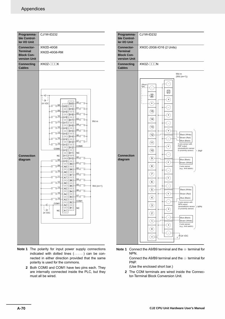
Appendices
A-70 CJ2 CPU Unit Hardware User’s Manual
Note 1 The polarity for input power supply connectionsindicated with dotted lines ( ) can be con-nected in either direction provided that the samepolarity is used for the commons.
2 Both COM0 and COM1 have two pins each. Theyare internally connected inside the PLC, but theymust all be wired.
Note 1 Connect the A9/B9 terminal and the terminal forNPN.Connect the A9/B9 terminal and the terminal forPNP. (Use the enclosed short bar.)
2 The COM terminals are wired inside the Connec-tor-Terminal Block Conversion Unit.
Programma-ble Control-ler I/O Unit
CJ1W-ID232
Connector-Terminal Block Con-version Unit
XW2D-40G6XW2D-40G6-RM
Connecting Cables
XW2Z-@@@K
Connection diagram
A20
A11
A12
A13
A14
A15
A16
A17
A18
A19
B20
B11
B12
B13
B14
B15
B16
B17
B18
B19
A10
A1
A2
A3
A4
A5
A6
A7
A8
A9
B10
B1
B2
B3
B4
B5
B6
B7
B8
B9
08
09
10
11
12
13
14
15
09
08
10
11
12
13
14
15
00
01
02
03
04
05
06
07
00NC
NC
NCNC
COM0COM0
COM1COM1
01
02
03
04
05
06
07
24 VDC
24 VDC
Wd (m+1)
Wd m
Programma-ble Control-ler I/O Unit
CJ1W-ID232
Connector-Terminal Block Con-version Unit
XW2C-20G6-IO16 (2 Units)
Connecting Cables
XW2Z-@@@N
Connection diagram
0
1
2
3
4
5
6
7
8
9
10
11
12
13
14
15
A9B9
A10B10
24 VDC
(Short bar)
Wd m(Wd (m+1))
PNP
NPN
Black (White)Brown (Red)Blue (Black)
Blue (Black)Brown (White)
Black (White)
Brown (Red)
Blue (Black)
3-wire sensor with PNP output (photoelectric sensor or proximity sensor)
3-wire sensor with NPN output (photoelectric sensor or proximity sensor)
2-wire sensor (e.g., limit switch)
Blue (Black)Brown (White)
2-wire sensor (e.g., limit switch)
+
��
+�
�
+
+
+
�
�
+
+
�
�
+
�
+
+
�
�+

A-71
Appendices
CJ2 CPU Unit Hardware User’s Manual
A-1 Specifications of B
asic I/O U
nitsA
ppA
-1-4 Connecting C
onnector-Terminal B
lock C
onversion Units and I/O
Relay Term
inals
Note 1 The polarity for input power supply connectionsindicated with dotted lines ( ) can be con-nected in either direction provided that the samepolarity is used for the commons.
2 Both COM0 and COM1 have two pins each. Theyare internally connected inside the PLC, but theymust all be wired.
Note 1 Connect the A9/B9 terminal and the terminal forNPN.Connect the A9/B9 terminal and the terminal forPNP. (Use the enclosed short bar.)
2 The COM terminals are wired inside the Connec-tor-Terminal Block Conversion Unit.
Programma-ble Control-ler I/O Unit
CJ1W-ID233
Connector-Terminal Block Con-version Unit
XW2D-40G6XW2D-40G6-RM
Connecting Cables
XW2Z-@@@K
Connection diagram
A20
A11
A12
A13
A14
A15
A16
A17
A18
A19
B20
B11
B12
B13
B14
B15
B16
B17
B18
B19
A10
A1
A2
A3
A4
A5
A6
A7
A8
A9
B10
B1
B2
B3
B4
B5
B6
B7
B8
B9
08
09
10
11
12
13
14
15
09
08
10
11
12
13
14
15
00
01
02
03
04
05
06
07
00NC
NC
NCNC
COM0COM0
COM1COM1
01
02
03
04
05
06
07
24 VDC
24 VDC
Wd (m+1)
Wd m
Programma-ble Control-ler I/O Unit
CJ1W-ID233
Connector-Terminal Block Con-version Unit
XW2C-20G6-IO16 (2 Units)
Connecting Cables
XW2Z-@@@N
Connection diagram
0
1
2
3
4
5
6
7
8
9
10
11
12
13
14
15
A9B9
A10B10
24 VDC
(Short bar)
Wd m(Wd (m+1))
PNP
NPN
Black (White)Brown (Red)Blue (Black)
Blue (Black)Brown (White)
Black (White)
Brown (Red)
Blue (Black)
3-wire sensor with PNP output (photoelectric sensor or proximity sensor)
3-wire sensor with NPN output (photoelectric sensor or proximity sensor)
2-wire sensor (e.g., limit switch)
Blue (Black)Brown (White)
2-wire sensor (e.g., limit switch)
+
��
+�
�
+
+
+
�
�
+
+
�
�
+
�
+
+
�
�+

Appendices
A-72 CJ2 CPU Unit Hardware User’s Manual
Note 1 The polarity for input power supply connectionsindicated with dotted lines ( ) can be con-nected in either direction provided that the samepolarity is used for the commons for rows A and B.
2 COM0, COM1, COM2, and COM3 have two pinseach. They are internally connected inside thePLC, but they must all be wired.
Note 1 Connect the A9/B9 terminal and the terminal forNPN.Connect the A9/B9 terminal and the terminal forPNP. (Use the enclosed short bar.)
2 The COM terminals are wired inside the Connec-tor-Terminal Block Conversion Unit.
Programma-ble Control-ler I/O Unit
CJ1W-ID261
Connector-Terminal Block Con-version Unit
XW2D-40G6XW2D-40G6-RF
Connecting Cables
XW2Z-@@@B
Connection diagram
A20
A11
A12
A13
A14
A15
A16
A17
A18
A19
B20
B11
B12
B13
B14
B15
B16
B17
B18
B19
A10
A1
A2
A3
A4
A5
A6
A7
A8
A9
B10
B1
B2
B3
B4
B5
B6
B7
B8
B9
15
COM0(COM2)
NC
14
13
12
11
10
09
08
NC
07
COM0(COM2)
06
05
04
03
02
01
00
15
COM1(COM3)
NC
14
13
12
11
10
09
08
NC
07
COM1(COM3)
06
05
04
03
02
01
00
24VDC
24VDC
CN1 ( CN2 )Wd m(Wd (m+2))
Wd (m+1)(Wd (m+3))
Programma-ble Control-ler I/O Unit
CJ1W-ID261
Connector-Terminal Block Con-version Unit
XW2C-20G6-IO16 (2 Units)
Connecting Cables
XW2Z-@@@D
Connection diagram
0
1
2
3
4
5
6
7
8
9
10
11
12
13
14
15
A9B9
A10B10
24 VDC
CN1CN2
Wd m and m+1(Wd m+2 and m+3)
(Short bar)
PNP
NPN
Black (White)Brown (Red)Blue (Black)
Blue (Black)Brown (White)
Black (White)
Brown (Red)
Blue (Black)
3-wire sensor with PNP output (photoelectric sensor or proximity sensor)
3-wire sensor with NPN output (photoelectric sensor or proximity sensor)
2-wire sensor (e.g., limit switch)
Blue (Black)Brown (White)
2-wire sensor (e.g., limit switch)
( )
+
��
+
�
+
�
+
�
�
+
�
+
+
+
�
�
+
+
+
�
�

A-73
Appendices
CJ2 CPU Unit Hardware User’s Manual
A-1 Specifications of B
asic I/O U
nitsA
ppA
-1-4 Connecting C
onnector-Terminal B
lock C
onversion Units and I/O
Relay Term
inals
Note 1 The polarity for input power supply connectionsindicated with dotted lines ( ) can be con-nected in either direction provided that the samepolarity is used for the commons.
2 COM0, COM1, COM2, and COM3 have two pinseach. They are internally connected inside thePLC, but they must all be wired.
Note 1 Connect the A9/B9 terminal and the terminal forNPN.Connect the A9/B9 terminal and the terminal forPNP. (Use the enclosed short bar.)
2 The COM terminals are wired inside the Connec-tor-Terminal Block Conversion Unit.
Programma-ble Control-ler I/O Unit
CJ1W-ID262
Connector-Terminal Block Con-version Unit
XW2D-40G6XW2D-40G6-RM
Connecting Cables
XW2Z-@@@K
Connection diagram
08
09
10
11
12
13
14
15
09
08
10
11
12
13
14
15
00
01
02
03
04
05
06
07
00NC
NC
NCNC
01
02
03
04
05
06
07
24 VDC
24 VDC
COM0COM0
COM1COM1
CN1CN2
A20
A11
A12
A13
A14
A15
A16
A17
A18
A19
B20
B11
B12
B13
B14
B15
B16
B17
B18
B19
A10
A1
A2
A3
A4
A5
A6
A7
A8
A9
B10
B1
B2
B3
B4
B5
B6
B7
B8
B9
(COM2)(COM2)
(COM3)(COM3)
( )
Wd m(Wd (m+2))
Wd (m+1)(Wd (m+3))
Programma-ble Control-ler I/O Unit
CJ1W-ID262
Connector-Terminal Block Con-version Unit
XW2C-20G6-IO16 (2 Units)
Connecting Cables
XW2Z-@@@N
Connection diagram
0
1
2
3
4
5
6
7
8
9
10
11
12
13
14
15
A9B9
A10B10
CN1
24 VDC
Wd m and m+1(Wd m+2 and m+3)
PNP
NPN
Black (White)Brown (Red)Blue (Black)
Blue (Black)Brown (White)
Black (White)
Brown (Red)
Blue (Black)
3-wire sensor with PNP output (photoelectric sensor or proximity sensor)
3-wire sensor with NPN output (photoelectric sensor or proximity sensor)
2-wire sensor (e.g., limit switch)
Blue (Black)Brown (White)
2-wire sensor (e.g., limit switch)
( )CN2
(Short bar)
+
��
+�
+
�
+
+
�
�
+
+
�
�
+
�
+
�
+
+�

Appendices
A-74 CJ2 CPU Unit Hardware User’s Manual
� Outputs
Note The +V terminals and COM terminals are internallyconnected inside the PLC, but they must all be wired.
Note 1 Connect the A9/B9 terminal and the terminal.Connect the A10/B10 terminal and the terminal. (Use the enclosed short bar.)
2 The COM terminals are wired inside the Connec-tor-Terminal Block Conversion Unit.
Programma-ble Control-ler I/O Unit
CJ1W-OD231
Connector-Terminal Block Con-version Unit
XW2D-40G6XW2D-40C6
Connecting Cables
XW2Z-@@@BXW2Z-@@@BU
Connection diagram
A20
A11
A12
A13
A14
A15
A16
A17
A18
A19
B20
B11
B12
B13
B14
B15
B16
B17
B18
B19
A10
A1
A2
A3
A4
A5
A6
A7
A8
A9
B10
B1
B2
B3
B4
B5
B6
B7
B8
B9
14
15
+V
13
12
11
10
09
08
COM0
07
COM0
06
05
04
03
02
01
00
14
15
13
12
11
10
09
08
COM1
07
COM1
06
05
04
03
02
01
00
12to24VDC
L
L
L
L
L
L
L
L
L
L
L
L
L
L
L
L
L
L
L
L
L
L
L
L
L
L
L
L
L
L
L
L
Wd mWd (m+1)
+V
+V+V
12to24VDC
Programma-ble Control-ler I/O Unit
CJ1W-OD231
Connector-Terminal Block Con-version Unit
XW2C-20G6-IO16 (2 Units)
Connecting Cables
XW2Z-@@@L
Connection diagram
0
1
2
3
4
5
6
7
8
9
10
11
12
13
14
15
A9B9
A10B10
COM0
15
14
13
12
11
10
09
08
07
06
05
04
03
02
01
00
12 to 24 VDC
+V
(COM1)
(Short bar)
(Short bar)
Solenoid valve, etc.
Wd m(Wd (m+1))
Solenoid valve, etc.
+�
+
�
+
+
�
�
�
+
+
�
+
�
�
+
+
++
�
��

A-75
Appendices
CJ2 CPU Unit Hardware User’s Manual
A-1 Specifications of B
asic I/O U
nitsA
ppA
-1-4 Connecting C
onnector-Terminal B
lock C
onversion Units and I/O
Relay Term
inals
Note The COM (+V) terminals and 0 V terminals are inter-nally connected inside the PLC, but they must all bewired.
Note 1 Connect the A9/B9 terminal and the terminal.Connect the A10/B10 terminal and the terminal. (Use the enclosed short bar.)
2 The COM terminals are wired inside the Connec-tor-Terminal Block Conversion Unit.
Programma-ble Control-ler I/O Unit
CJ1W-OD232
Connector-Terminal Block Con-version Unit
XW2D-40G6
Connecting Cables
XW2Z-@@@K
Connection diagram
24 VDC
24 VDC
A20
A11
A12
A13
A14
A15
A16
A17
A18
A19
B20
B11
B12
B13
B14
B15
B16
B17
B18
B19
A10
A1
A2
A3
A4
A5
A6
A7
A8
A9
B10
B1
B2
B3
B4
B5
B6
B7
B8
B9
11
10
12
13
14
15
10
11
12
13
14
15
03
0209
0108
00
04
05
06
07
0V0V
0 V0V
0209
0108
00
03
04
05
06
07
L
L
L
L
L
L
L
L
L
L
L
L
L
L
L
L
L
L
L
L
L
L
L
L
L
L
L
L
L
L
L
L
COM1(+V)COM1
(+V)
Wd (m+1)
COM0 (+V)COM0 (+V)
Wd m
Programma-ble Control-ler I/O Unit
CJ1W-OD232
Connector-Terminal Block Con-version Unit
XW2C-20G6-IO16 (2 Units)
Connecting Cables
XW2Z-@@@N
Connection diagram
0
1
2
3
4
5
6
7
8
9
10
11
12
13
14
15
A9B9
A10B10
15
14
13
12
11
10
09
08
07
06
05
04
03
02
01
00
24 VDC
Solenoid valve, etc.
Solenoid valve, etc.
COM0
+V
(COM1)
(Short bar)
(Short bar)
Wd m(Wd (m+1))
+
��
+�
+
�
+
�
+
�
+
�
�
+
+
+
�
�
�
+
+
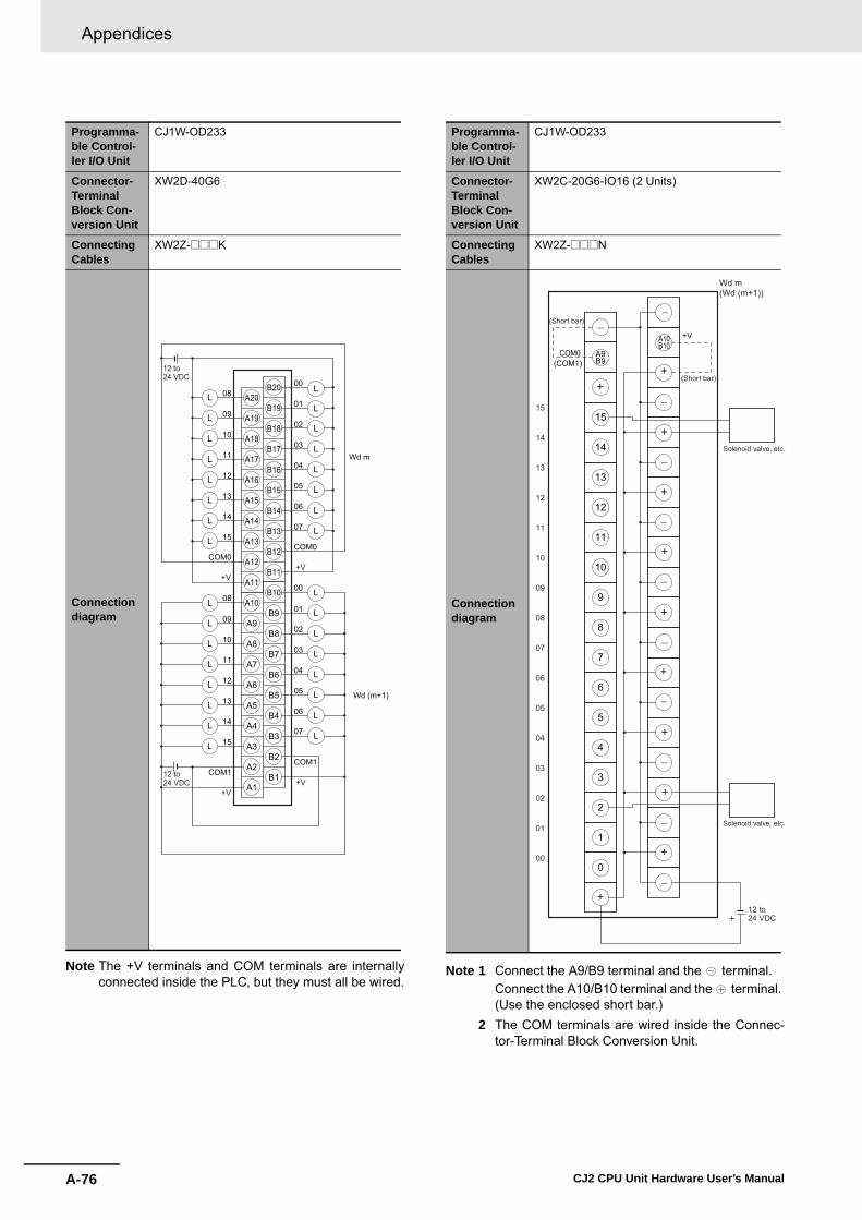
Appendices
A-76 CJ2 CPU Unit Hardware User’s Manual
Note The +V terminals and COM terminals are internallyconnected inside the PLC, but they must all be wired.
Note 1 Connect the A9/B9 terminal and the terminal.Connect the A10/B10 terminal and the terminal. (Use the enclosed short bar.)
2 The COM terminals are wired inside the Connec-tor-Terminal Block Conversion Unit.
Programma-ble Control-ler I/O Unit
CJ1W-OD233
Connector-Terminal Block Con-version Unit
XW2D-40G6
Connecting Cables
XW2Z-@@@K
Connection diagram
12 to24 VDC
A20
A11
A12
A13
A14
A15
A16
A17
A18
A19
B20
B11
B12
B13
B14
B15
B16
B17
B18
B19
A10
A1
A2
A3
A4
A5
A6
A7
A8
A9
B10
B1
B2
B3
B4
B5
B6
B7
B8
B9
11
10
12
13
14
15
10
11
12
13
14
15
03
0209
0108
00
04
05
06
07
COM0COM0
COM1COM1
0209
0108
00
03
04
05
06
07
L
L
L
L
L
L
L
L
L
L
L
L
L
L
L
L
L
L
L
L
L
L
L
L
L
L
L
L
L
L
L
L
Wd m
12 to24 VDC
Wd (m+1)
+V+V
+V+V
Programma-ble Control-ler I/O Unit
CJ1W-OD233
Connector-Terminal Block Con-version Unit
XW2C-20G6-IO16 (2 Units)
Connecting Cables
XW2Z-@@@N
Connection diagram
0
1
2
3
4
5
6
7
8
9
10
11
12
13
14
15
A9B9
A10B10
15
14
13
12
11
10
09
08
07
06
05
04
03
02
01
00
12 to 24 VDC
Solenoid valve, etc.
Solenoid valve, etc.
COM0
+V
(COM1)
(Short bar)
(Short bar)
Wd m(Wd (m+1))
+
��
+�
+
�
+
�
�
+
+
�
+
�
+
�
+
+
�
�+

A-77
Appendices
CJ2 CPU Unit Hardware User’s Manual
A-1 Specifications of B
asic I/O U
nitsA
ppA
-1-4 Connecting C
onnector-Terminal B
lock C
onversion Units and I/O
Relay Term
inals
Note The +V terminals and COM terminals are internallyconnected inside the PLC, but they must all be wired.
Note 1 Connect the A9/B9 terminal and the terminal.Connect the A10/B10 terminal and the terminal. (Use the enclosed short bar.)
2 The COM terminals are wired inside the Connec-tor-Terminal Block Conversion Unit.
Programma-ble Control-ler I/O Unit
CJ1W-OD234
Connector-Terminal Block Con-version Unit
XW2D-40G6
Connecting Cables
XW2Z-@@@K
Connection diagram
12 to24 VDC
A20
A11
A12
A13
A14
A15
A16
A17
A18
A19
B20
B11
B12
B13
B14
B15
B16
B17
B18
B19
A10
A1
A2
A3
A4
A5
A6
A7
A8
A9
B10
B1
B2
B3
B4
B5
B6
B7
B8
B9
11
10
12
13
14
15
10
11
12
13
14
15
03
0209
0108
00
04
05
06
07
COM0COM0
COM1COM1
0209
0108
00
03
04
05
06
07
L
L
L
L
L
L
L
L
L
L
L
L
L
L
L
L
L
L
L
L
L
L
L
L
L
L
L
L
L
L
L
L
Wd m
12 to24 VDC
Wd (m+1)
+V+V
+V+V
Programma-ble Control-ler I/O Unit
CJ1W-OD234
Connector-Terminal Block Con-version Unit
XW2C-20G6-IO16 (2 Units)
Connecting Cables
XW2Z-@@@N
Connection diagram
0
1
2
3
4
5
6
7
8
9
10
11
12
13
14
15
A9B9
A10B10
15
14
13
12
11
10
09
08
07
06
05
04
03
02
01
00
12 to 24 VDC
Solenoid valve, etc.
Solenoid valve, etc.
COM0
+V
(COM1)
(Short bar)
(Short bar)
Wd m(Wd (m+1))
+
��
+�
+
�
+
�
�
+
+
�
+
�
+
�
+
+
�
�+

Appendices
A-78 CJ2 CPU Unit Hardware User’s Manual
Note The +V terminals and COM terminals are internallyconnected inside the PLC, but they must all be wired.
Note 1 Connect the A9/B9 terminal and the terminal.Connect the A10/B10 terminal and the terminal. (Use the enclosed short bar.)
2 The COM terminals are wired inside the Connec-tor-Terminal Block Conversion Unit.
Programma-ble Control-ler I/O Unit
CJ1W-OD261
Connector-Terminal Block Con-version Unit
XW2D-40G6XW2D-40C6
Connecting Cables
XW2Z-@@@BXW2Z-@@@BU
Connection diagram
A20
A11
A12
A13
A14
A15
A16
A17
A18
A19
B20
B11
B12
B13
B14
B15
B16
B17
B18
B19
A10
A1
A2
A3
A4
A5
A6
A7
A8
A9
B10
B1
B2
B3
B4
B5
B6
B7
B8
B9
14
15
13
12
11
10
09
08
COM0
07
COM0
06
05
04
03
02
01
00
14
15
13
12
11
10
09
08
COM1
07
COM1
06
05
04
03
02
01
00
12 to 24VDC
L
L
L
L
L
L
L
L
L
L
L
L
L
L
L
L
L
L
L
L
L
L
L
L
L
L
L
L
L
L
L
L
CN1 CN2( )
+V+V
(COM3)(COM2)
Wd m(Wd (m+2))
Wd (m+1)(Wd (m+3))
+V+V
(COM3)(COM2)
12 to 24VDC
Programma-ble Control-ler I/O Unit
CJ1W-OD261
Connector-Terminal Block Con-version Unit
XW2C-20G6-IO16 (2 Units)
Connecting Cables
XW2Z-@@@L
Connection diagram
0
1
2
3
4
5
6
7
8
9
10
11
12
13
14
15
A9B9
A10B10
CN1
( CN2 )
COM
15
14
13
12
11
10
09
08
07
06
05
04
03
02
01
00
12 to 24 VDC
Solenoid valve, etc.
+V
(Short bar)
Wd m and (m+1)(Wd (m+2) and (m+3))
(Short bar)
Solenoid valve, etc.
+�
+
�
�
+
+
�
+
�
+
�
+
�
�
+
+
�
+
��
+

A-79
Appendices
CJ2 CPU Unit Hardware User’s Manual
A-1 Specifications of B
asic I/O U
nitsA
ppA
-1-4 Connecting C
onnector-Terminal B
lock C
onversion Units and I/O
Relay Term
inals
Note The COM (+V) terminals and 0 V terminals are inter-nally connected inside the PLC, but they must all bewired.
Note 1 Connect the A9/B9 terminal and the terminal.Connect the A10/B10 terminal and the terminal. (Use the enclosed short bar.)
2 The COM terminals are wired inside the Connec-tor-Terminal Block Conversion Unit.
Programma-ble Control-ler I/O Unit
CJ1W-OD262
Connector-Terminal Block Con-version Unit
XW2D-40G6
Connecting Cables
XW2Z-@@@K
Connection diagram
24 VDC
24 VDC
11
10
12
13
14
15
10
11
12
13
14
15
03
0209
0108
00
04
05
06
07
0 V
0 V0 V
0209
0108
00
03
04
05
06
07
L
L
L
L
L
L
L
L
L
L
L
L
L
L
L
L
L
L
L
L
L
L
L
L
L
L
L
L
L
L
L
L
A20
A11
A12
A13
A14
A15
A16
A17
A18
A19
B20
B11
B12
B13
B14
B15
B16
B17
B18
B19
A10
A1
A2
A3
A4
A5
A6
A7
A8
A9
B10
B1
B2
B3
B4
B5
B6
B7
B8
B9
CN1 CN2( )
Wd m(Wd (m+2))
COM0 (+V)(COM2 (+V))
0 V
COM0 (+V)(COM2 (+V))
Wd (m+1)(Wd (m+3))
COM1 (+V)(COM3 (+V))COM1 (+V)
(COM3 (+V))
Programma-ble Control-ler I/O Unit
CJ1W-OD262
Connector-Terminal Block Con-version Unit
XW2C-20G6-IO16 (2 Units)
Connecting Cables
XW2Z-@@@N
Connection diagram
0
1
2
3
4
5
6
7
8
9
10
11
12
13
14
15
A9B9
A10B10
CN1
COM0
15
14
13
12
11
10
09
08
07
06
05
04
03
02
01
00
24 VDC
Solenoid valve, etc.
Solenoid valve, etc.
(Short bar)
Wd m and (m+1)(Wd (m+2) and (m+3))
(Short bar)
+V
(COM1)
( )CN2
�
+
�
+
�
+
�
+
�
+
�
�
+
+
�
+
�
+
+
�
�+

Appendices
A-80 CJ2 CPU Unit Hardware User’s Manual
Note The +V terminals and COM terminals are internallyconnected inside the PLC, but they must all be wired.
Note 1 Connect the A9/B9 terminal and the terminal.Connect the A10/B10 terminal and the terminal. (Use the enclosed short bar.)
2 The COM terminals are wired inside the Connec-tor-Terminal Block Conversion Unit.
Programma-ble Control-ler I/O Unit
CJ1W-OD263
Connector-Terminal Block Con-version Unit
XW2D-40G6
Connecting Cables
XW2Z-@@@K
Connection diagram
12 to 24 VDC
12 to 24 VDC
11
10
12
13
14
15
10
11
12
13
14
15
03
0209
0108
00
04
05
06
07
0209
0108
00
03
04
05
06
07
L
L
L
L
L
L
L
L
L
L
L
L
L
L
L
L
L
L
L
L
L
L
L
L
L
L
L
L
L
L
L
L
COM0COM0
COM1COM1
CN1
A20
A11
A12
A13
A14
A15
A16
A17
A18
A19
B20
B11
B12
B13
B14
B15
B16
B17
B18
B19
A10
A1
A2
A3
A4
A5
A6
A7
A8
A9
B10
B1
B2
B3
B4
B5
B6
B7
B8
B9
( )
Wd m(Wd (m+2))
CN2
(COM2)(COM2) +V
+V
(COM3)
+V
Wd (m+1)(Wd (m + 3))
(COM3)
+V
Programma-ble Control-ler I/O Unit
CJ1W-OD263
Connector-Terminal Block Con-version Unit
XW2C-20G6-IO16 (2 Units)
Connecting Cables
XW2Z-@@@N
Connection diagram
0
1
2
3
4
5
6
7
8
9
10
11
12
13
14
15
A9B9
A10B10
CN1
COM0
15
14
13
12
11
10
09
08
07
06
05
04
03
02
01
00
12 to 24 VDC
Solenoid valve, etc.
(Short bar)
Wd m and (m+1)(Wd (m+2) and (m+3))
(Short bar)
+V
(COM1)
( )CN2
Solenoid valve, etc.
�+
�
+
+
�
+
�
+
�
+
�
+
�
+
�
+
�+
+
��

A-81
Appendices
CJ2 CPU Unit Hardware User’s Manual
A-1 Specifications of B
asic I/O U
nitsA
ppA
-1-4 Connecting C
onnector-Terminal B
lock C
onversion Units and I/O
Relay Term
inals
� Inputs and Outputs
Note 1 The polarity for input power supply connections indicated with dotted lines ( ) can be connected in either direc-tion.
2 The COM terminals are internally connected inside the PLC, but they must all be wired.
Programma-ble Control-ler I/O Unit
CJ1W-MD231
Connector-Terminal Block Con-version Unit
XW2D-20G6
Connecting Cables
XW2Z-@@@A
Connection diagram
A10
A1
A2
A3
A4
A5
A6
A7
A8
A9
B10
B1
B2
B3
B4
B5
B6
B7
B8
B9
CN2
A10
A1
A2
A3
A4
A5
A6
A7
A8
A9
B10
B1
B2
B3
B4
B5
B6
B7
B8
B9
CN1
L
L
L
L
L
L
L
L
L
L
L
L
L
L
L
L
07
06
05
04
03
02
01
00
07
COM
NC
06
05
04
03
02
01
00
15
COM
NC
14
13
12
11
10
09
08
15
14
13
12
11
10
09
08
12 to 24 VDC
12 to 24 VDC
24VDC 24
VDC
Wd m (OUT)
+V+V
COM (0 V)COM (0 V)
Wd (m+1) (IN)

Appendices
A-82 CJ2 CPU Unit Hardware User’s Manual
Programmable Con-troller I/O Unit
CJ1W-MD231
Connector-Terminal Block Conversion Unit
XW2C-20G6-IO16
Connecting Cables XW2Z-@@@A
Connection diagram
Note 1 Connect the A9/B9 terminal and the terminal.Connect the A10/B10 terminal and the
terminal. (Use the enclosed short bar.)
2 The COM terminals are wired inside theConnector-Terminal Block ConversionUnit.
Note 1 Connect the A9/B9 terminal and the terminal for NPN. Connect the A9/B9 terminal and the terminal for PNP. (Use the enclosed short bar.)
2 The COM terminals are wired inside theConnector-Terminal Block ConversionUnit.
0
1
2
3
4
5
6
7
8
9
10
11
12
13
14
15
A9B9
A10B10
COM0
15
14
13
12
11
10
09
08
07
06
05
04
03
02
01
00
12 to 24 VDC
CN1 (OUT)
Solenoid valve, etc.
Wd m
(Short bar)
+V
(COM1)
(Shortbar)
Solenoid valve, etc.
+�
+
�
+
�
+
�
+
�
+
�
+
�
+
�
+
�
++
��
0
1
2
3
4
5
6
7
8
9
10
11
12
13
14
15
A9B9
A10B10
CN2 Wd (m+1)
(Short bar)
(IN)
24 VDC
PNP
NPN
Black (White)Brown (Red)Blue (Black)
Blue (Black)Brown (White)
Black (White)
Brown (Red)
Blue (Black)
3-wire sensor with PNP output (photoelectric sensor or proximity sensor)
3-wire sensor with NPN output (photoelectric sensor or proximity sensor)
2-wire sensor (e.g., limit switch)
Blue (Black)Brown (White)2-wire sensor (e.g., limit switch)
+
��
+�
+
�
+
�
+
�
+
�
+
�
+
�
+
�
�
+
+

A-83
Appendices
CJ2 CPU Unit Hardware User’s Manual
A-1 Specifications of B
asic I/O U
nitsA
ppA
-1-4 Connecting C
onnector-Terminal B
lock C
onversion Units and I/O
Relay Term
inals
Note 1 The polarity for input power supply connectionsindicated with dotted lines ( ) can be con-nected in either direction.
2 The COM terminals and 0V terminal are internallyconnected inside the PLC, but they must all bewired.
Note 1 The polarity for input power supply connectionsindicated with dotted lines ( ) can be con-nected in either direction.
2 The COM terminals and +V terminals are inter-nally connected inside the PLC, but they must allbe wired.
Programma-ble Control-ler I/O Unit
CJ1W-MD232
Connector-Terminal Block Con-version Unit
XW2D-20G6
Connecting Cables
XW2Z-@@@X
Connection diagram
A10
A1
A2
A3
A4
A5
A6
A7
A8
A9
B10
B1
B2
B3
B4
B5
B6
B7
B8
B9
CN2
A10
A1
A2
A3
A4
A5
A6
A7
A8
A9
B10
B1
B2
B3
B4
B5
B6
B7
B8
B9
CN1
L
L
L
L
L
L
L
L
L
L
L
L
L
L
L
L
10
09
08
11
12
13
14
15
0 V
09
08
NC
10
11
12
13
14
15
COM
01
00
NC
02
03
04
05
06
07
COM
02
01
00
03
04
05
06
07
0 V24 VDC
COM (+V)COM (+V)
Wd m (OUT)
Wd (m+1) (OUT)
24 VDC
Programma-ble Control-ler I/O Unit
CJ1W-MD233
Connector-Terminal Block Con-version Unit
XW2D-20G6
Connecting Cables
XW2Z-@@@X
Connection diagram
A10
A1
A2
A3
A4
A5
A6
A7
A8
A9
B10
B1
B2
B3
B4
B5
B6
B7
B8
B9
CN2
A10
A1
A2
A3
A4
A5
A6
A7
A8
A9
B10
B1
B2
B3
B4
B5
B6
B7
B8
B9
CN1
10
09
08
11
12
13
14
15
09
08
NC
10
11
12
13
14
15
COM
01
00
NC
02
03
04
05
06
07
COM
02
01
00
03
04
05
06
07 L
L
L
L
L
L
L
L
L
L
L
L
L
L
L
L
12 to 24VDC
24VDC
24VDC
12 to 24VDC
Wd m (OUT)
COM (0 V)COM (0 V)
+V+V
Wd (m+1) (IN)

Appendices
A-84 CJ2 CPU Unit Hardware User’s Manual
Programmable Con-troller I/O Unit
CJ1W-MD261
Connector-Terminal Block Conversion Unit
XW2D-40G6XW2D-40G6RF
Connecting Cables XW2Z-@@@B
Connection diagram
Note The +V terminals and COM terminals areinternally connected inside the PLC, butthey must all be wired.
Note 1 The polarity for input power supply con-nections indicated with dotted lines( ) can be connected in eitherdirection provided that the same polarityis used for the commons for rows A andB.
2 Both COM2 and COM3 have two pinseach. They are internally connectedinside the PLC, but they must all bewired.
A20
A11
A12
A13
A14
A15
A16
A17
A18
A19
B20
B11
B12
B13
B14
B15
B16
B17
B18
B19
A10
A1
A2
A3
A4
A5
A6
A7
A8
A9
B10
B1
B2
B3
B4
B5
B6
B7
B8
B9
14
15
13
12
11
10
09
08
COM0
07
COM0
06
05
04
03
02
01
00
14
15
13
12
11
10
09
08
COM1
07
COM1
06
05
04
03
02
01
00
12 to 24 VDC
L
L
L
L
L
L
L
L
L
L
L
L
L
L
L
L
L
L
L
L
L
L
L
L
L
L
L
L
L
L
L
L
CN1
+V+V
(OUT)
Wd m Wd (m+1)
+V+V
12 to 24 VDC
A20
A11
A12
A13
A14
A15
A16
A17
A18
A19
B20
B11
B12
B13
B14
B15
B16
B17
B18
B19
A10
A1
A2
A3
A4
A5
A6
A7
A8
A9
B10
B1
B2
B3
B4
B5
B6
B7
B8
B9
15
COM2
NC
14
13
12
11
10
09
08
NC
07
COM2
06
05
04
03
02
01
00
15
COM3
NC
14
13
12
11
10
09
08
NC
07
COM3
06
05
04
03
02
01
00
24 VDC
CN2 (IN)Wd (m+3)Wd (m+2)
24 VDC

A-85
Appendices
CJ2 CPU Unit Hardware User’s Manual
A-1 Specifications of B
asic I/O U
nitsA
ppA
-1-4 Connecting C
onnector-Terminal B
lock C
onversion Units and I/O
Relay Term
inals
Programmable Con-troller I/O Unit
CJ1W-MD261
Connector-Terminal Block Conversion Unit
XW2C-20G6-IO16 (2 Units) XW2C-20G6-IO16 (2 Units)
Connecting Cables XW2Z-@@@L XW2Z-@@@D
Connection diagram
Note 1 Connect the A9/B9 terminal and the terminal.Connect the A10/B10 terminal and the
terminal. (Use the enclosed short bar.)
2 The COM terminals are wired inside theConnector-Terminal Block ConversionUnit.
Note 1 Connect the A9/B9 terminal and the terminal for NPN. Connect the A9/B9 terminal and the terminal for PNP. (Use the enclosed short bar.)
2 The COM terminals are wired inside theConnector-Terminal Block ConversionUnit.
0
1
2
3
4
5
6
7
8
9
10
11
12
13
14
15
A9B9
A10B10
COM0
15
14
13
12
11
10
09
08
07
06
05
04
03
02
01
00
CN2
12 to 24 VDC
Solenoid valve, etc.
Solenoid valve, etc.
Wd m(Wd (m+1))
(Short bar)
+V
(COM1)
(Shortbar)
(OUT)
+
��
�+
+
�
�
+
+
+
�
�
+
�
+
+
�
�
�
+
+
0
1
2
3
4
5
6
7
8
9
10
11
12
13
14
15
A9B9
A10B10
CN2
24 VDC
PNP
NPN
Black (White)Brown (Red)Blue (Black)
Blue (Black)Brown (White)
Black (White)
Brown (Red)
Blue (Black)
3-wire sensor with PNP output (photoelectric sensor or proximity sensor)
3-wire sensor with NPN output (photoelectric sensor or proximity sensor)
2-wire sensor (e.g., limit switch)
Blue (Black)Brown (White)
2-wire sensor (e.g., limit switch)
Wd (m+2)(Wd (m+3))
(Short bar)
(IN)
+
��
+
+
+
+
+
+
+
+
+
+
�
�
�
�
�
�
�
�
�
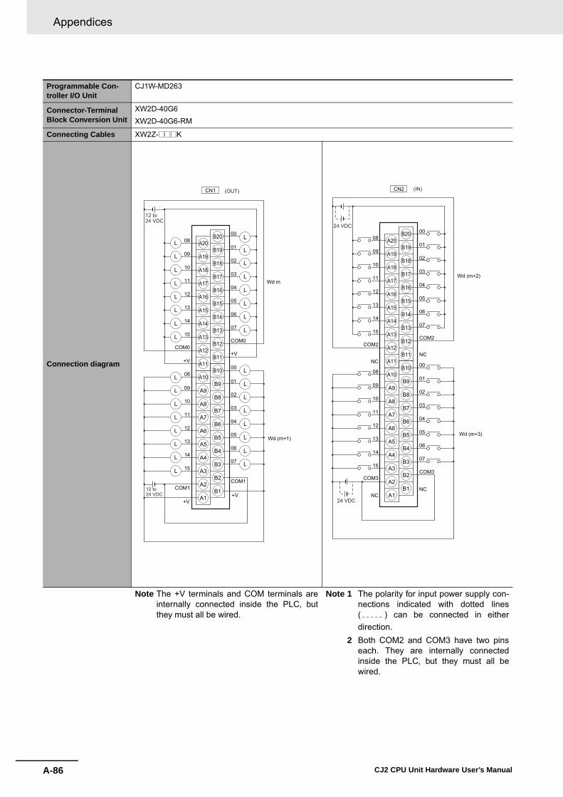
Appendices
A-86 CJ2 CPU Unit Hardware User’s Manual
Programmable Con-troller I/O Unit
CJ1W-MD263
Connector-Terminal Block Conversion Unit
XW2D-40G6XW2D-40G6-RM
Connecting Cables XW2Z-@@@K
Connection diagram
Note The +V terminals and COM terminals areinternally connected inside the PLC, butthey must all be wired.
Note 1 The polarity for input power supply con-nections indicated with dotted lines( ) can be connected in eitherdirection.
2 Both COM2 and COM3 have two pinseach. They are internally connectedinside the PLC, but they must all bewired.
CN1
12 to 24 VDC
12 to 24 VDC
A20
A11
A12
A13
A14
A15
A16
A17
A18
A19
B20
B11
B12
B13
B14
B15
B16
B17
B18
B19
A10
A1
A2
A3
A4
A5
A6
A7
A8
A9
B10
B1
B2
B3
B4
B5
B6
B7
B8
B9
11
10
12
13
14
15
+V
10
11
12
13
14
15
03
0209
0108
00
04
05
06
07
+VCOM0
COM0
COM1COM1
0209
0108
00
03
04
05
06
07
L
L
L
L
L
L
L
L
L
L
L
L
L
L
L
L
L
L
L
L
L
L
L
L
L
L
L
L
L
L
L
L
Wd m
Wd (m+1)
+V+V
(OUT)
A20
A11
A12
A13
A14
A15
A16
A17
A18
A19
B20
B11
B12
B13
B14
B15
B16
B17
B18
B19
A10
A1
A2
A3
A4
A5
A6
A7
A8
A9
B10
B1
B2
B3
B4
B5
B6
B7
B8
B9
08
09
10
11
12
13
14
15
09
08
10
11
12
13
14
15
00
01
02
03
04
05
06
07
00NC
NC
NCNC
COM2COM2
COM3COM3
01
02
03
04
05
06
07
24 VDC
24 VDC
Wd (m+2)
CN2 (IN)
Wd (m+3)

A-87
Appendices
CJ2 CPU Unit Hardware User’s Manual
A-1 Specifications of B
asic I/O U
nitsA
ppA
-1-4 Connecting C
onnector-Terminal B
lock C
onversion Units and I/O
Relay Term
inals
Programmable Con-troller I/O Unit
CJ1W-MD263
Connector-Terminal Block Conversion Unit
XW2C-20G6-IO16 (2 Units)
Connecting Cables XW2Z-@@@N
Connection diagram
Note 1 Connect the A9/B9 terminal and the terminal.Connect the A10/B10 terminal and the
terminal. (Use the enclosed short bar.)
2 The COM terminals are wired inside theConnector-Terminal Block ConversionUnit.
Note 1 Connect the A9/B9 terminal and the terminal for NPN. Connect the A9/B9 terminal and the terminal for PNP. (Use the enclosed short bar.)
2 The COM terminals are wired inside theConnector-Terminal Block ConversionUnit.
0
1
�
2
3
4
5
6
7
8
9
10
11
12
13
14
15
�
A9B9
�
�
�
�
�
�
�
�
�
�
�
�
�
�
�
�
�
�
�
A10B10
�
COM0
15
14
13
12
11
10
09
08
07
06
05
04
03
02
01
00
12 to 24 VDC
CN1
Solenoid valve, etc.
Wd m(Wd (m+1))
(Short bar)
+V
(COM1)
(Shortbar)
(OUT)
Solenoid valve, etc.
0
1
2
3
4
5
6
7
8
9
10
11
12
13
14
15
A9B9
A10B10
CN2
24 VDC
PNP
NPN
Black (White)Brown (Red)Blue (Black)
Blue (Black)Brown (White)
Black (White)
Brown (Red)
Blue (Black)
3-wire sensor with PNP output (photoelectric sensor or proximity sensor)
3-wire sensor with NPN output (photoelectric sensor or proximity sensor)
2-wire sensor (e.g., limit switch)
Blue (Black)Brown (White)
2-wire sensor (e.g., limit switch)
Wd (m+2)(Wd (m+3))
(Short bar)
(IN)
+
��
�
�
�
�
�
�
�
�
�
+
+
+
+
+
+
+
+
+
+

Appendices
A-88 CJ2 CPU Unit Hardware User’s Manual
Programmable Con-troller I/O Unit
CJ1W-MD563
Connector-Terminal Block Conversion Unit
XW2D-40G6XW2D-40G6-RM
Connecting Cables XW2Z-@@@K
Connection diagram
Note 1 The +V terminals and COM terminalsare internally connected inside the PLC,but they must all be wired.
2 The power supply voltage for the CJ1W-MD563 is 5 V.
Note 1 The COM terminals are internally con-nected inside the PLC, but they must allbe wired.
2 The power supply voltage for the CJ1W-MD563 is 5 V.
CN1
5 VDC
5 VDC
A20
A11
A12
A13
A14
A15
A16
A17
A18
A19
B20
B11
B12
B13
B14
B15
B16
B17
B18
B19
A10
A1
A2
A3
A4
A5
A6
A7
A8
A9
B10
B1
B2
B3
B4
B5
B6
B7
B8
B9
11
10
12
13
14
15
10
11
12
13
14
15
03
0209
0108
00
04
05
06
07
COM0COM0
COM1COM1
0209
0108
00
03
04
05
06
07
L
L
L
L
L
L
L
L
L
L
L
L
L
L
L
L
L
L
L
L
L
L
L
L
L
L
L
L
L
L
L
L
Wd m
Wd (m+1)
+V+V
+V+V
(OUT)
A20
A11
A12
A13
A14
A15
A16
A17
A18
A19
B20
B11
B12
B13
B14
B15
B16
B17
B18
B19
A10
A1
A2
A3
A4
A5
A6
A7
A8
A9
B10
B1
B2
B3
B4
B5
B6
B7
B8
B9
08
09
10
11
12
13
14
15
09
08
10
11
12
13
14
15
00
01
02
03
04
05
06
07
00NC
NC
NCNC
COM2COM2
COM3COM3
01
02
03
04
05
06
07
5 VDC
5 VDC
Wd (m+2)
CN2 (IN)
Wd (m+3)

A-89
Appendices
CJ2 CPU Unit Hardware User’s Manual
A-1 Specifications of B
asic I/O U
nitsA
ppA
-1-4 Connecting C
onnector-Terminal B
lock C
onversion Units and I/O
Relay Term
inals
Connection examples and internal connection diagrams for I/O Relay Terminals connected to Basic I/OUnits are shown below.
� InputsG7TC I/O Relay Terminals
Connection Diagrams for I/O Relay Terminals
G7TC-ID16 G7TC-IA16
TOP VIEW TOP VIEW
Note 1 Inputs to the PLC Input Units and I/O Relay Terminalsuse isolated contacts. “00” to “15” are the input bitnumbers for the PLC Input Unit and the input numbersfor the I/O Relay Terminal.
2 Use the G78-04 short bar to short to the common ter-minal.
Note 1 Inputs to the PLC Input Units and I/O Relay Terminalsuse isolated contacts. “00” to “15” are the input bit num-bers for the PLC Input Unit and the input numbers forthe I/O Relay Terminal.
2 Use the G78-04 short bar to short to the common termi-nal.
PLC
G7TC
15
14
13
12
11
10
9
8
7
6
5
4
3
2
1
0
C15
C14
C13
C12
C11
C10
C9
C8
C7
C6
C5
C4
C3
C2
C1
C0
NC NC
15
14
13
12
11
10
09
08
07
06
05
04
03
02
01
00
Relay side
+ �
PLC
15
14
13
12
11
10
9
8
7
6
5
4
3
2
1
0
NC
C15
C14
C13
C12
C11
C10
C9
C8
C7
C6
C5
C4
C3
C2
C1
C0
NC
14
13
12
11
10
09
08
07
06
05
04
03
02
01
00
15G7TC
Relay side
+ �

Appendices
A-90 CJ2 CPU Unit Hardware User’s Manual
� OutputsG70D-V Relay Terminals
G70D-VSOC16 G70D-VSOC16+G70D-ET
TOP VIEW TOP VIEW
Note 1 All outputs are independent. Outputs on the PLC Out-put Unit and I/O Relay Terminal are isolated. “00” to“15” are the output bit numbers for the PLC OutputUnit and the output numbers for the I/O Relay Termi-nal.
2 Use the G6D-4-SB short bar to short to the commonterminal.
Note 1 All outputs are independent. Outputs on the PLC Out-put Unit and I/O Relay Terminal are isolated. “00” to“15” are the output bit numbers for the PLC OutputUnit and the output numbers for the I/O Relay Termi-nal.
2 Use the G6D-4-SB short bar to short to the commonterminal.
PLC
15
14
13
12
11
10
09
08
07
06
05
04
03
02
01
00
A15
A14
A13
A12
A11
A10
A9
A8
A7
A6
A5
A4
A3
A2
A1
A0
B15
B14
B13
B12
B11
B10
B9
B8
B7
B6
B5
B4
B3
B2
B1
B0
Power supply
G70D-VSOC16
Back side24
VDC 0
L
L
L
L
L
L
L
L
L
L
L
L
L
L
L
L
PLC
15
14
13
12
11
10
09
08
07
06
05
04
03
02
01
00
B15
B14
B13
B12
B11
B10
B9
B8
B7
B6
B5
B4
B3
B2
B1
B0
C15
C14
C13
C12
C11
C10
C9
C8
C7
C6
C5
C4
C3
C2
C1
C0
A15
A14
A13
A12
A11
A10
A9
A8
A7
A6
A5
A4
A3
A2
A1
A0
G70D-VSOC16 G70D-ET
24VDC 0
L
L
L
L
L
L
L
L
L
L
L
L
L
L
L
L
Power supply
Back side

A-91
Appendices
CJ2 CPU Unit Hardware User’s Manual
A-1 Specifications of B
asic I/O U
nitsA
ppA
-1-4 Connecting C
onnector-Terminal B
lock C
onversion Units and I/O
Relay Term
inals
G70D Relay Terminals
G70D-SOC16 G70D-SOC08
TOP VIEW TOP VIEW
Note Every two outputs share a common. The current suppliedis 3 A per common. Outputs on the PLC Output Unit andI/O Relay Terminal are isolated. “00” to “15” are the out-put bit numbers for the PLC Output Unit and the outputnumbers for the I/O Relay Terminal.
Note 1 All outputs are independent. Outputs on the PLC Out-put Unit and I/O Relay Terminal are isolated. “00” to“07” are the output bit numbers for the PLC OutputUnit and the output numbers for the I/O Relay Termi-nal.
2 Use the G6D-4-SB short bar to short to the commonterminal.
PLC
B7
B5
B5
B3
B3
B1
NC
NC
B6
B4
B4
B2
B2
B0
0
NC
15
13
11
09
07
05
03
01
00
02
04
06
08
10
12
14
Power supply
A15
A13
A11
A9
A7
A5
A3
A2
A0
A4
A6
A8
A10
A12
A1
A14
G70D-SOC16
Relay side24
VDC
L
L
L
L
L
L
L
L
L
L
L
L
L
L
L
L
PLC
07
06
05
04
03
02
01
00
A7
A6
A5
A4
A3
A2
A1
A0
B7
B6
B5
B4
B3
B2
B1
B0
Power supply
G70D-SOC08
Relay side24
VDC0V
L
L
L
L
L
L
L
L

Appendices
A-92 CJ2 CPU Unit Hardware User’s Manual
G70R Relay Terminals
Note 1 All outputs are independent. Outputs on the PLCOutput Unit and I/O Relay Terminal are isolated.“00” to “07” are the output bit numbers for the PLCOutput Unit and the output numbers for the I/ORelay Terminal.
2 Use the G6D-4-SB short bar to short to the com-mon terminal.
G7TC I/O Relay Terminals
Note 1 All outputs are independent. Outputs on the PLCOutput Unit and I/O Relay Terminal are isolated.“00” to “15” are the output bit numbers for the PLCOutput Unit and the output numbers for the I/ORelay Terminal.
2 The G7TC-OC08 has only 8 outputs and thereforedoes not have 8 to 15 and C8 to C15.
3 Use the G78-04 short bar to short to the commonterminal.
G70R-SOC08
TOP VIEW
PLC
07
06
05
04
03
02
01
00
A7
A6
A5
A4
A3
A2
A1
A0
B7
B6
B5
B4
B3
B2
B1
B0
Power supply
G70R-SOC08
24VDC0V
L
L
L
L
L
L
L
L
G7TC-OC16/OC08
TOP VIEW
PLC
Powersupply
15
14
13
12
11
10
9
8
7
6
5
4
3
2
1
0
NC
C15
C14
C13
C12
C11
C10
C9
C8
C7
C6
C5
C4
C3
C2
C1
C0
NC
G7TC
Relay side
15
14
13
12
11
10
09
08
07
06
05
04
03
02
01
00
L
L
L
L
L
L
L
L
L
L
L
L
L
L
L
L

A-93
Appendices
CJ2 CPU Unit Hardware User’s Manual
A-1 Specifications of B
asic I/O U
nitsA
ppA
-1-4 Connecting C
onnector-Terminal B
lock C
onversion Units and I/O
Relay Term
inals
G7TC I/O Relay Terminals
Note 1 All outputs are independent. Outputs on the PLCOutput Unit and I/O Relay Terminal are isolated.“00” to “15” are the output bit numbers for the PLCOutput Unit and the output numbers for the I/ORelay Terminal.
2 Use the G78-04 short bar to short to the commonterminal.
G70A-ZOC16 Relay Terminal Socket
Note 1 The above diagram is an example with the G2R-1-S(N) mounted to the G70A-ZOC16-3.
2 All outputs are independent. Outputs on the PLCOutput Unit and I/O Relay Terminal are isolated.“00” to “15” are the output bit numbers for the PLCOutput Unit and the output numbers for the I/ORelay Terminal.
G7TC-OC16-1
TOP VIEW
PLC
15
14
13
12
11
10
09
08
07
06
05
04
03
02
01
00
Powersupply
15
14
13
12
11
10
9
8
7
6
5
4
3
2
1
0
NC
C15
C14
C13
C12
C11
C10
C9
C8
C7
C6
C5
C4
C3
C2
C1
C0
NC
G7TC
Relay side
L
L
L
L
L
L
L
L
L
L
L
L
L
L
L
L
G70A-ZOC16-3+G2R-1-S (16 Units)
TOP VIEW
PLC
G70A-ZOC16-3 + G2R-1-S (16 Units)
Relay side
12
14
22
24 21
32
34 31
42
44 41
52
54 51
62
64 61
72
74 71
82
84 81
92
94 91
102
104 101
112
114 111
122
124 121
132
134 131
142
144 141
152
154 151
162
164 161
11
Powersupply
00
00
01
01
02
02
03
03
04
04
05
05
06
06
07
07
08
08
09
09
10
10
11
11
12
12
13
13
14
14
15
15L
L
L
L
L
L
L
L
L
L
L
L
L
L
L
L
L
L
L
L
L
L
L
L
L
L
L
L
L
L
L
L
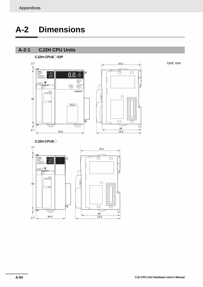
Appendices
A-94 CJ2 CPU Unit Hardware User’s Manual
A-2 Dimensions
CJ2H-CPU6@-EIP
CJ2H-CPU6@
A-2-1 CJ2H CPU Units
6579.8 74.5
2.7
2.7
90
66.2 Unit: mm
6548.8 74.5
2.7
2.7
66.2
90

A-95
Appendices
CJ2 CPU Unit Hardware User’s Manual
A-2 D
imensions
App
A-2-2 C
J2M C
PU
Units
CJ2M-CPU3@
CJ2M-CPU1@
A-2-2 CJ2M CPU Units
76.22.7
90
62 752.7
84.5
Unit: mm
76.2
7584.5
2.7
31
90
2.7

Appendices
A-96 CJ2 CPU Unit Hardware User’s Manual
A-2-3 Power Supply Units
CJ1W-PA205R
CJ1W-PA205C
POWER
PA205R
DC24VAC240V
OUTPUTRUN
INPUTAC100-240V
L2/N
L1
658081.6
90
Unit: mm
Years
POWERCJ1W-PA205C
TEST
658081.6
90
NC
NC
AC100-240VINPUT
L2/N
L1
L+
ALARMOUTPUTDC30V,50mA
NORMAL:ONALARM :OFF
Unit: mm

A-97
Appendices
CJ2 CPU Unit Hardware User’s Manual
A-2 D
imensions
App
A-2-3 Pow
er Supply Units
CJ1W-PA202
CJ1W-PD025
CJ1W-PD022
654581.6
90
POWER
PA202
INPUT
NC
NC
AC100-240V
L2/N
L1
Unit: mm
656081.6
90
POWER
PD025
DC24V+INPUT
NC
NC
Unit: mm
652781.6
90
POWER
PD022 Unit: mm
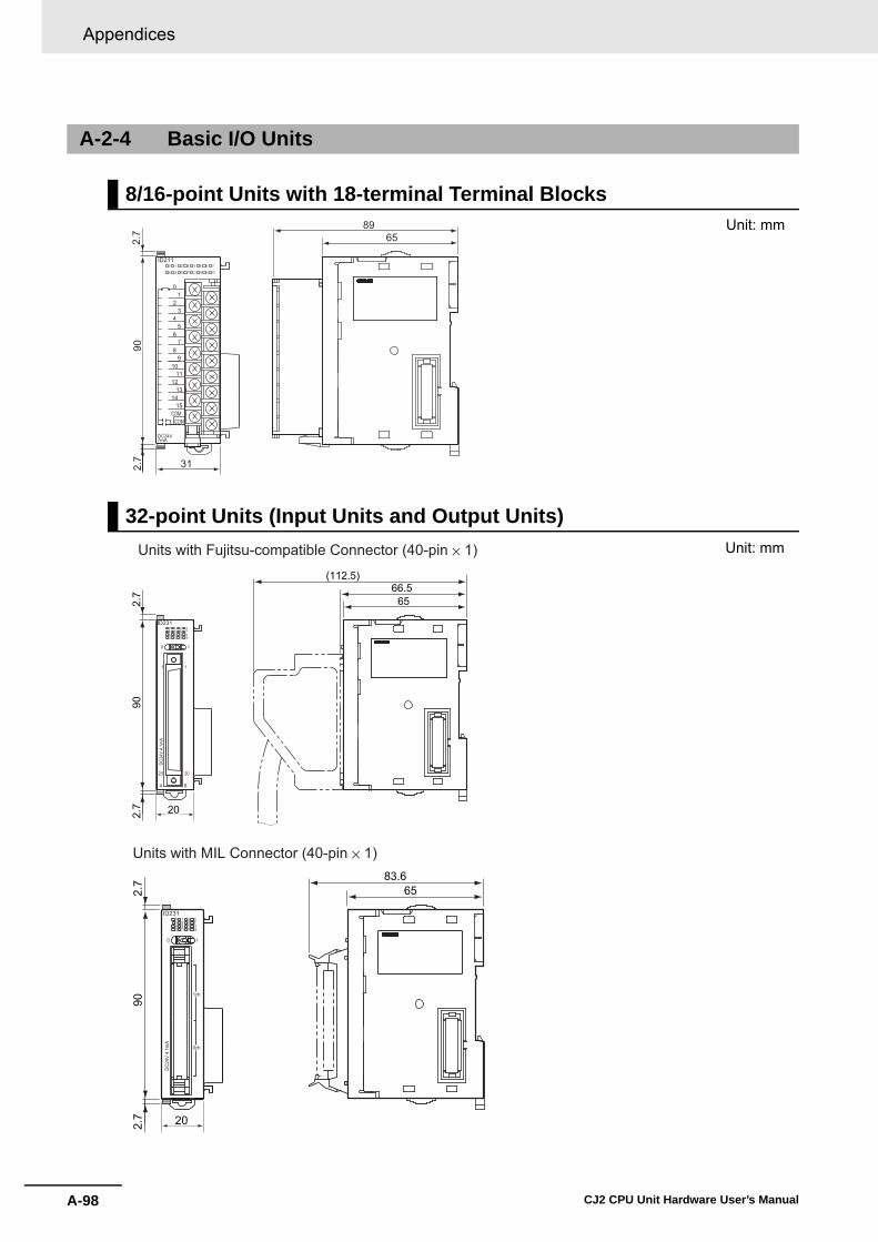
Appendices
A-98 CJ2 CPU Unit Hardware User’s Manual
A-2-4 Basic I/O Units
8/16-point Units with 18-terminal Terminal Blocks
32-point Units (Input Units and Output Units)
7.27.2
09
6589
ID2110 1 2 3 4 5 6 7
8 9 10 11 12 13 14 15
01
32
45
76
89
1110
1213
1415
DC24V7mA
COMCOM
31
Unit: mm
7.27.2
09
6566.5
(112.5)
ID2310
0
1
20
A B
20
1
1
1 2 34 5 6 78 9 10 1112 13 14 15
Am1.4 V42CD
20
Units with Fujitsu-compatible Connector (40-pin × 1)
7.27.2
09
6583.6
ID2310
0 1
1ch
0ch
1 2 34 5 6 78 9 10 1112 13 14 15
Am1.4 V42CD
20
Units with MIL Connector (40-pin × 1)
Unit: mm
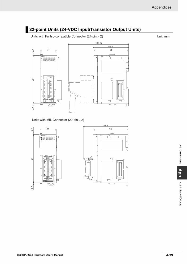
A-99
Appendices
CJ2 CPU Unit Hardware User’s Manual
A-2 D
imensions
App
A-2-4 B
asic I/O U
nits
32-point Units (24-VDC Input/Transistor Output Units)Units with Fujitsu-compatible Connector (24-pin × 2)
7.27.2
09
6566.5
(112.5)
31
Units with MIL Connector (20-pin × 2)
7.27.2
09
6583.6
31
Unit: mm

Appendices
A-100 CJ2 CPU Unit Hardware User’s Manual
64-point Units (Input Units, Output Units, 24-VDC Input/Transistor Output Units, TTL I/O Units)Units with Fujitsu-compatible Connector (40-pin × 2)
7.27.2
09
6566.5
(112.5)
31
Units with MIL Connector (40-pin × 2)
7.27.2
09
6583.6
31
Unit: mm

A-101
Appendices
CJ2 CPU Unit Hardware User’s Manual
A-2 D
imensions
App
A-2-5 I/O
Control U
nit and I/O Interface U
nit
A-2-5 I/O Control Unit and I/O Interface Unit
A-2-6 I/O Memory Card
A-2-7 Serial Option Boards (CJ2M-CPU3@ Only)
CP1W-CIF01 RS-232C Option Board
OUTIC101IC101
7.27.2
09
69.3
6568
(140)
20
7.27.2
09
69.3
6568
(140)
OUT INII101
31
CJ1W-IC101I/O Control Unit
CJ1W-II101I/O Interface Unit
Unit: mm
36.43.3
42.8
Unit: mm
0.15
37.3
35.9
35.9
5.1
16.513.5
16.519.7
Unit: mm

Appendices
A-102 CJ2 CPU Unit Hardware User’s Manual
CP1W-CIF11 RS-422A/485 Option Board
CP1W-CIF12 RS-422A/485 Option Board
8.9
16.513.5
15.7
16.5
0.1537
.335
.9
35.9
Unit: mm
7.9
16.5
0.15
37.3
36.4
36.4 28.230.3
Unit: mm

A-103
Appendices
CJ2 CPU Unit Hardware User’s Manual
A-3 Fatal and N
on-fatal Error Details
App
A-3-1 Fatal E
rrors
A-3 Fatal and Non-fatal Error Details
This appendix describes the fatal and non-fatal errors that can occur in the CPU Unit.
Operation will stop if a fatal error occurs. Information on the fatal error is displayed on the Error TabPage opened from the CX-Programmer's PLC Error Window. Check the details on the error based onthe message that is displayed, and the error flags and error information in the Auxiliary Area, and takesuitable countermeasures. The following list shows the fatal errors.
A-3-1 Fatal Errors
Fatal error Cycle Time Exceeded Error (0x809F)
I/O Bus Error (0x80C0 to 0x80C7, 0x80CE , or 80CF)
I/O Setting Error (0x80E0)
Too Many I/O Points Error (0x80E1)
Unit Number Duplication Error (0x80E9)
Rack Number Duplication Error (0x80EA)
Program Error (0x80F0) Instruction error
Indirect BCD error
Illegal access error
No END error
Task error
Differentiation overflow error
Illegal instruction error
UM overflow error
Memory Error (0x80F1)
Memory Card Transfer Error (0x80F4)
FALS(007) Error (0xC101 to 0xC2FF)
Version Error (0x80F2)

Appendices
A-104 CJ2 CPU Unit Hardware User’s Manual
• The table of fatal errors is arranged in ascending order of error codes.• When two or more errors occur at the same time, the error code of the more serious error will be
recorded in A400. • If the IOM Hold Bit hasn't been turned ON to protect I/O memory, all nonretained areas of I/O memory
will be cleared when a fatal error other than FALS(007) occurs.
• If the IOM Hold Bit is ON, the contents of I/O memory will be retained but all outputs will be turned OFF.
*1 A404.00 to A404.07 contain the error slot number (00 to 09) in binary. “0F hex” indicates that the slot cannot be deter-mined.“0B hex” indicates a bus error occurred for the built-in EtherNet/IP port.“0E hex” indicates the End Cover is not connected to the CPU Rack or an Expansion Rack.
*2 The maximum processing time for an interrupt task will not be stored in A440 if High-speed interrupt function is enabled inthe PLC Setup.
Table of Fatal Errors
Error Error
code (in A400)
Error flag (Auxiliary
Area)
Flag and word data Probable cause Possible remedy
Cycle Time Exceeded Error
0x809F A401.08: Cycle Time Exceeded Flag
--- The cycle time has exceeded the maximum cycle time (watch cycle time) set in the PLC Setup.
Change the program to reduce the cycle time or change the maximum cycle time setting. Check the Maximum Interrupt Task Processing Time in A440 and see if the Cycle Time Watch Time can be changed.*2 The cycle time can be reduced by divid-ing unused parts of the program into tasks, jumping unused instructions in tasks, and disabling cyclic refreshing of Special I/O Units that don't require fre-quent refreshing.
I/O Bus Error 0x80C0 to 0x80C7, 0x80CE, or 0x80CF
A401.14: I/O Bus Error Flag
A404: I/O Bus Error Slot and Rack Num-bers
Error has occurred in the bus line between the CPU and I/O Units or the End Cover is not connected to the CPU Rack or an Expansion Rack.*1
A404.08 to A404.15 contain the error rack number (00 to 03) in binary. 0F hex indicates that the rack cannot be determined.0E hex indicates the End Cover is not connected to the CPU Rack or an Expansion Rack.
Try turning the power OFF and ON again. If the error isn't corrected, turn the power OFF and check cable connections between the I/O Units and Racks and the End Covers. Check for damage to the cable or Units. Turn the Rack's power supply OFF and then ON again.
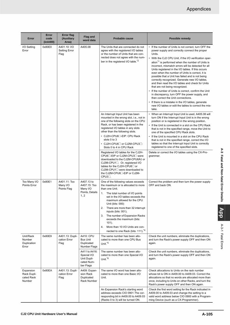
A-105
Appendices
CJ2 CPU Unit Hardware User’s Manual
A-3 Fatal and N
on-fatal Error Details
App
A-3-1 Fatal E
rrors
Error Error code
(inA400)
Error flag (Auxiliary
Area)
Flag and word data Probable cause Possible remedy
I/O Setting Error
0x80E0 A401.10: I/O Setting Error Flag
A405.08 The Units that are connected do not agree with the registered I/O tables or the number of Units that are con-nected does not agree with the num-ber in the registered I/O table.*2
• If the number of Units is not correct, turn OFF the power supply and correctly connect the proper Units.
• With the CJ2 CPU Unit, if the I/O verification oper-ation*1 is performed when the number of Units is incorrect, mismatch errors will be detected for all Units registered in the I/O tables. If this occurs even when the number of Units is correct, it is possible that a Unit has failed and is not being correctly recognized. Generate new I/O tables, and then read the I/O tables and check for Units that are not being recognized.
• If the number of Units is correct, confirm the Unit in discrepancy, turn OFF the power supply, and then correct the Unit connections.
• If there is a mistake in the I/O tables, generate new I/O tables or edit the tables to correct the mis-take.
An Interrupt Input Unit has been mounted in the wrong slot, i.e., not in one of the following slots on the CPU Rack, or has been registered in the registered I/O tables in any slots other than the following slots.
• CJ2H-CPU6@-EIP: CPU Rack slots 0 to 3
• CJ2H-CPU6@ or CJ2M-CPU3@:Slots 0 to 4 in CPU Rack
• When an Interrupt Input Unit is used, A405.08 will turn ON if the Interrupt Input Unit is in the wrong position or is registered in the wrong position.
• If the Unit is connected in a slot on the CPU Rack that is not in the specified range, move the Unit to one of the specified CPU Rack slots.
• If the Unit is mounted in a slot on the CPU Rack that is not in the specified range, correct the I/O tables so that the Interrupt Input Unit is correctly registered to one of the specified slots.
Registered I/O tables for the CJ2H-CPU6@-EIP or CJ2M-CPU3@ were downloaded to the CJ2M-CPU6ņ or CJ2M-CPU1@. Or, registered I/O tables for the CJ2H-CPU6@ or CJ2M-CPU1@ were downloaded to the CJ2M-CPU6@-EIP or CJ2M-CPU3@.
Delete or correct the I/O tables using the CX-Pro-grammer.
Too Many I/O Points Error
0x80E1 A401.11: Too Many I/O Points Flag
A407.13 to A407.15: Too Many I/O Points, Details 1, 2
One of the following values exceeds the maximum or is allocated to more than one Unit.
1. The total number of I/O points set in the I/O tables exceeds the maximum allowed for the CPU Unit (bits: 000)
2. There are more than 32 interrupt inputs (bits: 001).
3. The number of Expansion Racks exceeds the maximum (bits: 101).
4. More than 10 I/O Units are con-nected to one Rack (bits: 111).*4
Correct the problem and then turn the power supply OFF and back ON.
Unit/Rack Number Duplication Error
0x80E9 A401.13: Dupli-cation Error Flag
A410: CPU Bus Unit Duplicated Number Flags
The same number has been allo-cated to more than one CPU Bus Unit.*5
Check the unit numbers, eliminate the duplications, and turn the Rack's power supply OFF and then ON again.
A411 to A416: Special I/O Unit Dupli-cated Num-ber Flags
The same number has been allo-cated to more than one Special I/O Unit.*6
Check the unit numbers, eliminate the duplications, and turn the Rack's power supply OFF and then ON again.
Expansion Rack Dupli-cated Rack Number
0x80EA A401.13: Dupli-cation Error Flag
A409: Expan-sion Rack Duplicated Rack Number
The same I/O word has been allo-cated to more than one Basic I/O Unit.
Check allocations to Units on the rack number whose bit is ON in A409.00 to A409.03. Correct the allocations so that no words are allocated more than once, including to Units on other Racks, and turn the Rack's power supply OFF and then ON again.
An Expansion Rack's starting word address exceeds CIO 0901.The cor-responding bit in A409.00 to A409.03 (Racks 0 to 3) will be turned ON.
Check the first word setting for the Rack indicated in A409.00 to A409.03 and change the setting to a valid word address below CIO 0900 with a Program-ming Device (such as a CX-Programmer).

Appendices
A-106 CJ2 CPU Unit Hardware User’s Manual
Program Error 0x80F0 A401.09: Pro-gram Error Flag
A294 to A299: Program Error Information
The program is incorrect. See the fol-lowing rows of this table for details. The address at which the program stopped will be output to A298 and A299.
Check the program using A298/A299 and the error flags to find the mistake, and correct the program. Correct the program and then clear the error.
A295.11: No END error Be sure that there is an END(001) instruction at the end of the task specified in A294 (program stop task number).
A295.15: UM overflow error The last address in UM (user pro-gram memory) has been exceeded.
Transfer the program again.
A295.13: Differentiation overflow error Too many differentiated instruc-tions have been inserted or deleted during online editing.
Return to PROGRAM mode and transfer the pro-gram again.
A295.12: Task errorA task error has occurred. The follow-ing conditions will generate a task error.
1. There is no executable cyclic task.
2. There is no task that corre-sponds to the interrupt that was input. (Only when the Stop CPU on Instruction Error parameter inthe PLC Setup is set to Stop.)
Check the startup cyclic task attributes. Check the execution status of each task as controlled by TKON(820) and TKOF(821).Make sure that all of the task numbers specified in TKON(820), TKOF(821), and MSKS(690) instructions have corresponding tasks. Use MSKS(690) to mask any I/O or sched-uled interrupt tasks that are not being used and that do not have programs set for them.
A295.10: Illegal access error An illegal access error has occurred and the PLC Setup has been set to stop operation for an instruction error. The following are illegal access errors:
1. Reading/writing a parameter area.
2. Writing memory that is not installed.
3. Writing an EM bank that is EM file memory.
4. Writing to a read-only area.5. Indirect DM/EM address that is
not in BCD when BCD mode is specified.
Find the program address where the error occurred (A298/A299) and correct the instruction.
Indirect DM/EM BCD Error Flag (A295.09) turned ON: An indirect DM/EM BCD error has occurred, causing the AER Flag to turn ON. Also, the PLC Setup has been set to stop operation for an instruction error.
Find the program address where the error occurred using A298/A299 and correct the indirect address-ing (the indirect address or the word holding the indi-rect address) or change to binary mode.
Instruction Error Flag (A295.08) turned ON: Incorrect data values were provided in an operand when an attempt was made to execute an instruction, causing the ER Flag to turn ON, and the PLC Setup has been set to stop operation for an instruction error.
Check the Program Error Position (A298/A299) to find the reason that the ER Flag turned ON and cor-rect the operand data according to the descriptions of the instructions in the Instructions Reference Manual (Cat. No. W474).
A295.14: Illegal instruction errorThe program contains an instruction that cannot be executed.
Retransfer the program to the CPU Unit.
Error Error code
(inA400)
Error flag (Auxiliary
Area)
Flag and word data Probable cause Possible remedy
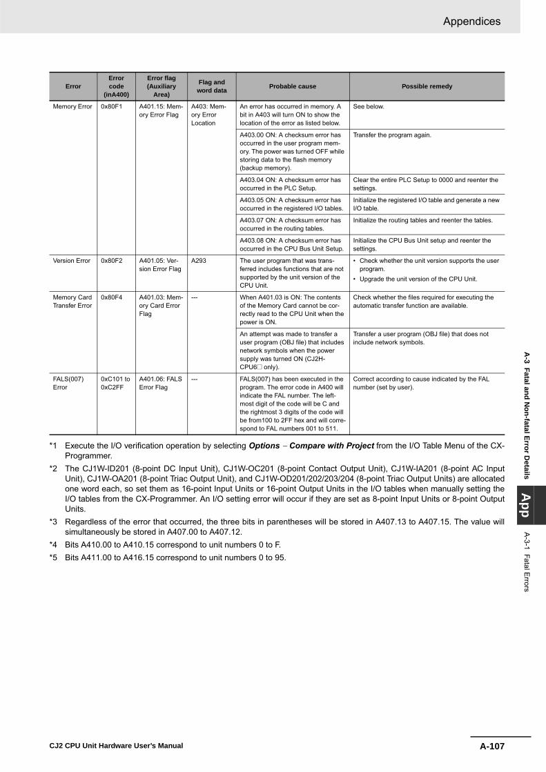
A-107
Appendices
CJ2 CPU Unit Hardware User’s Manual
A-3 Fatal and N
on-fatal Error Details
App
A-3-1 Fatal E
rrors
*1 Execute the I/O verification operation by selecting Options − Compare with Project from the I/O Table Menu of the CX-Programmer.
*2 The CJ1W-ID201 (8-point DC Input Unit), CJ1W-OC201 (8-point Contact Output Unit), CJ1W-IA201 (8-point AC InputUnit), CJ1W-OA201 (8-point Triac Output Unit), and CJ1W-OD201/202/203/204 (8-point Triac Output Units) are allocatedone word each, so set them as 16-point Input Units or 16-point Output Units in the I/O tables when manually setting theI/O tables from the CX-Programmer. An I/O setting error will occur if they are set as 8-point Input Units or 8-point OutputUnits.
*3 Regardless of the error that occurred, the three bits in parentheses will be stored in A407.13 to A407.15. The value willsimultaneously be stored in A407.00 to A407.12.
*4 Bits A410.00 to A410.15 correspond to unit numbers 0 to F. *5 Bits A411.00 to A416.15 correspond to unit numbers 0 to 95.
Memory Error 0x80F1 A401.15: Mem-ory Error Flag
A403: Mem-ory Error Location
An error has occurred in memory. A bit in A403 will turn ON to show the location of the error as listed below.
See below.
A403.00 ON: A checksum error has occurred in the user program mem-ory. The power was turned OFF while storing data to the flash memory (backup memory).
Transfer the program again.
A403.04 ON: A checksum error has occurred in the PLC Setup.
Clear the entire PLC Setup to 0000 and reenter the settings.
A403.05 ON: A checksum error has occurred in the registered I/O tables.
Initialize the registered I/O table and generate a new I/O table.
A403.07 ON: A checksum error has occurred in the routing tables.
Initialize the routing tables and reenter the tables.
A403.08 ON: A checksum error has occurred in the CPU Bus Unit Setup.
Initialize the CPU Bus Unit setup and reenter the settings.
Version Error 0x80F2 A401.05: Ver-sion Error Flag
A293 The user program that was trans-ferred includes functions that are not supported by the unit version of the CPU Unit.
• Check whether the unit version supports the user program.
• Upgrade the unit version of the CPU Unit.
Memory Card Transfer Error
0x80F4 A401.03: Mem-ory Card Error Flag
--- When A401.03 is ON: The contents of the Memory Card cannot be cor-rectly read to the CPU Unit when the power is ON.
Check whether the files required for executing the automatic transfer function are available.
An attempt was made to transfer a user program (OBJ file) that includes network symbols when the power supply was turned ON (CJ2H-CPU6@ only).
Transfer a user program (OBJ file) that does not include network symbols.
FALS(007) Error
0xC101 to 0xC2FF
A401.06: FALS Error Flag
--- FALS(007) has been executed in the program. The error code in A400 will indicate the FAL number. The left-most digit of the code will be C and the rightmost 3 digits of the code will be from100 to 2FF hex and will corre-spond to FAL numbers 001 to 511.
Correct according to cause indicated by the FAL number (set by user).
Error Error code
(inA400)
Error flag (Auxiliary
Area)
Flag and word data Probable cause Possible remedy

Appendices
A-108 CJ2 CPU Unit Hardware User’s Manual
Operation continues when a non-fatal error occurs. Connect the CX-Programmer to display the errormessage in the Error Log Dialog Box on the CX-Programmer.
The cause of the error can be determined from the error message and related Auxiliary Area flags andwords. The following list shows the non-fatal errors.
A-3-2 Non-fatal Errors
Non-fatal errors Duplicated Refreshing Error (CJ1: Interrupt task error) (0x008B)
PLC Setup Error (0x009B)
Basic I/O Error (0x009A)
Backup Memory Error (0x00F1)
Tag Memory Error (0x00F2)
System Work Error (0x00F3)
Battery Error (0x00F7)
CPU Bus Unit Error (0x0200 to 0x020F)
Special I/O Unit Error (0x0300 to 0x035F or 0x03FF)
CPU Bus Unit Setting Error (0x0400 to 0x040F)
Special I/O Unit Setting Error (0x0500 to 0x055F)
FAL(006) Error (0x4104 to 0x42FF)

A-109
Appendices
CJ2 CPU Unit Hardware User’s Manual
A-3 Fatal and N
on-fatal Error Details
App
• The table of non-fatal errors is arranged in ascending order of error codes.• When two or more errors occur at the same time, the error code of the more serious error will be
recorded in A400. • When the IOM Hold Bit is set to ON, I/O memory will be retained and outputs to the Output Unit will
turn OFF.
Table of Non-fatal Errors
Error Error code (in A400)
Error flag (Auxiliary
Area)
Flag and word data Probable cause Possible remedy
Duplicated Refreshing Error (CJ1: Interrupt task error)
0x008B A402.13: Dupli-cated Refresh Error Flag
A426: Unit number where duplicated refresh error occurred
ON when the Detect Duplicated Refresh Errors setting in the PLC Setup is set to Detect and one of the following occurs for the same Special I/O Unit.
• IORF(097), FIORF(225), IORD(222) or IOWR(223) in a cyclic task are competing with FIORF(225), IORF(097), IORD(222) or IOWR(223) in an interrupt task.
• IORF(097), FIORF(225), IORD(222) or IOWR(223) was executed in an interrupt task when I/O was being refreshed.*1
Check the program. Either disable detection of duplicated refresh errors in the PLC Setup or correct the problem in the program.
Basic I/O Error 0x009A A402.12: CJ-series Basic I/O Unit Error Flag
A408: Basic I/O Unit Error, Slot Number
An error has occurred in a Basic I/O Unit.*2 Check the Basic I/O Unit to see whether a fuse needs to be replaced.
PLC Setup Error
0x009B A402.10: PLC Setup Error Flag
--- There is a setting error in the PLC Setup. The location of the error is written to A406.
Change the indicated setting to a valid setting.
Option Board Error
0x00D1 A315.13 Option Board Error FlagA402.00 Other Non-fatal Error Flag
--- The Option Board was removed while the sys-tem was operating.
Option Board failure
Check the mating of the Option Board connector and reconnect the connector. If the Option Board still fails, replace it.
Backup Mem-ory Error
0x00F1 A315.15: Backup Mem-ory Error Flag
--- Writing to the built-in flash memory failed. Operation may not be possible the next time power is restored after a power interruption. Replace the CPU Unit.
Tag Memory Error*3
0x00F2 A315.12: Tag Memory Error Flag
--- An error occurred in memory where network tags are stored.
Transfer the program again.
System Work Error
0x00F3 A315.04: Sys-tem Work Error Flag
--- An error occurred in the memory for online edit-ing.
Operation may not be possible the next time power is restored after a power interruption. Trans-fer the program again.
Battery Error 0x00F7 A402.04: Bat-tery Error Flag
--- This error occurs when the PLC Setup has been set to detect battery errors and the CPU Unit's backup battery is missing or its voltage has dropped.
Check battery and replace if nec-essary. Change the PLC Setup setting if battery-free operation is being used.
CPU Bus Unit Error
0x0200 to 0x020F
A402.07: CPU Bus Unit Error Flag
A417: CPU Bus Unit Error, Unit Number Flags
An error occurred in a data exchange between the CPU Unit and a CPU Bus Unit.*4
Check the Unit indicated in A417. Refer to the Unit's operation man-ual to find and correct the cause of the error. Restart the Unit by toggling its Restart Bit or turn the power OFF and ON again. Replace the Unit if it won't restart.
Special I/O Unit Error
0x0300 to 0x035F or 0x03FF
A402.06: Spe-cial I/O Unit Error Flag
A418 to A423: Special I/O Unit Error, Unit Number Flags
An error occurred in a data exchange between the CPU Unit and a Special I/O Unit.*5
Check the Unit indicated in A418 to A423. Refer to the Unit's opera-tion manual to find and correct the cause of the error. Restart the Unit by toggling its Restart Bit or turn the power OFF and ON again. Replace the Unit if it won't restart.
CPU Bus Unit Setting Error
0x0400 to 0x040F
A402.03: CPU Bus Unit Set-ting Error Flag
A427: CPU Bus Unit Setting Error, Unit Number Flags
An installed CPU Bus Unit does not match the CPU Bus Unit registered in the I/O tables.*6
Change the registered I/O table.

Appendices
A-110 CJ2 CPU Unit Hardware User’s Manual
*1 If cyclic refreshing is not disabled in the PLC Setup for a Special I/O Unit and IORF(097), FIORF(225), IORD(222) orIOWR(223) is executed for the same Special I/O Unit in an interrupt task, a duplicate refreshing status will occur and anduplicated refreshing error will occur.
*2 A408 contains the errant rack/slot number. *3 CJ2H-CPU6@-EIP or CJ2M-CPU3@ only.*4 The corresponding flag in A417 is turned ON to indicate the problem Unit. *5 The corresponding flag in A418 to A423 is turned ON to indicate the problem Unit.*6 The corresponding flag in A427 will be ON. *7 The corresponding flag in A428 to A433 will be ON. *8 Executed FAL Number Flags in consecutive bits in A360 to A391 correspond to FAL numbers 001 to 511.
The error code in A400 will indicate the FAL number. The leftmost digit of the code will be 4 and the rightmost 3 digits of the code will be from 101 to 2FF hex and will corre-spond to FAL numbers 001 to 511.
Special I/O Unit Setting Error
0x0500 to 0x055F
A402.02: Spe-cial I/O Unit Setting Error Flag
A428 to A433: Special I/O Unit Setting Error, Unit Number Flags
An installed Special I/O Unit does not match the Special I/O Unit registered in the I/O tables.*7
Change the registered I/O table.
• A Unit that is specified for synchronous unit operation does not support synchronous unit operation. *7
• A Unit that is specified for synchronous unit operation does not exist.*7
Correct the settings for synchro-nous unit operation in the PLC Setup and transfer the PLC Setup again.
A Synchronous Unit that is specified for syn-chronous unit operation is not on the CPU Rack (the Synchronous Unit is on an Expansion Rack).*7
Move the Synchronous Unit to the CPU Rack. If I/O tables have been registered, correct the set-tings in the registered I/O tables.
FAL(006) Error 0x4101 to 0x42FF
A402.15: FAL Error Flag
A360 to A391: Executed FAL Number Flags
FAL(006) has been executed in program.*8 Correct according to cause indi-cated by FAL number (set by user).
Error Error code (in A400)
Error flag (Auxiliary
Area)
Flag and word data Probable cause Possible remedy

A-111
Appendices
CJ2 CPU Unit Hardware User’s Manual
A-4 C
onnecting to a Serial Port on the CPU
Unit
App
A-4 Connecting to a Serial Port on the CPU Unit
This appendix provides information on configurations and wiring methods when connecting variousfunctionality to a serial port on a CPU Unit.
With the following configurations, the serial port on a CJ2 CPU Unit can be used with an RS-232C orRS-422A/485 interface. In this appendix, serial ports on CPU Units with these interfaces are called RS-232C ports and RS-422A/485 ports.
� CPU Unit Built-in RS-232C Interface Specifications
• Connector Pin Arrangement
A-4-1 Serial Port Interface Types and Specifications
InterfaceModel RS-232C
RS-422A/485Not isolated Isolated
CJ2H-CPU6@(-EIP) Built into the CPU Unit as a standard feature.
A CJ1W-CIF11 RS-422A Converter is mounted directly to the built-in RS-232C inter-face.
The built-in RS-232C inter-face and an NT-AL001 RS-232C/RS-422A Link Adapter are connected with a cable.
CJ2M-CPU1@
CJ2M-CPU3@ A CP1W-CIF01 RS-232C Option Board is mounted.
A CP1W-CIF11 RS-422A/485 Option Board is mounted.
A CP1W-CIF12 RS-422A/485 Option Board is mounted.
RS-232C Interface Specifications
Pin No. Signal Name Direction1 FG Protection earth ---
2 SD (TXD) Send data Output
3 RD (RXD) Receive data Input
4 RS (RTS) Request to send Output
5 CS (CTS) Clear to send Input
6 5 V Power supply ---
7 DR (DSR) Data set ready Input
8 ER (DTR) Data terminal ready Output
9 SG (0 V) Signal ground ---
Connector hood FG Protection earth ---
5
1
9
6

Appendices
A-112 CJ2 CPU Unit Hardware User’s Manual
� CP1W-CIF01 RS-232C Option Board Specifications
• Connector Pin Arrangement
Precautions for Safe Use
Do not use the 5-V power from pin 6 of the RS-232C port on the CPU Unit for anything but theNT-AL001 Link Adapter, CJ1W-CIF11 RS-422A Converter, or NV3W-M@20L Programmable Ter-minal. The external device or the CPU Unit may be damaged.
�� Communications Specifications
*1 Baud rates for the RS-232C are specified only up to 19.2 kbps.The CJ Series supports serial communicationsfrom 38.4 kbps to 115.2 kbps, but some computers cannot support these speeds.Lower the baud rate if neces-sary.
Pin No. Signal Name Direction1 FG Protection earth ---2 SD (TXD) Send data Output3 RD (RXD) Receive data Input4 RS (RTS) Request to send Output5 CS (CTS) Clear to send Input6 5 V Power supply ---7 DR (DSR) Data set ready Input8 ER (DTR) Data terminal ready Output9 SG (0 V) Signal ground ---Connector hood FG Protection earth ---
Item SpecificationCommunications method Half duplex
Synchronization Start-stop
Baud rate 0.3/0.6/1.2/2.4/4.8/9.6/19.2/38.4/57.6/115.2 kbps*1
Transmission distance 15 m max.
Interface EIA RS-232C
Protocol Host Link, NT Link, 1:N, No-protocol, or Peripheral Bus
COMM
Front Back
1. Communications status indicators
2. RS-232C connector
3. CPU Unit connector
5
6
1
9

A-113
Appendices
CJ2 CPU Unit Hardware User’s Manual
A-4 C
onnecting to a Serial Port on the CPU
Unit
App
� CP1W-CIF11 and CP1W-CIF12 RS-422A/485 Option Board Specifications
• RS-422A/485 Terminal Block
• DIP Switch for Operation Settings
� Converting Built-in RS-232C to RS-422A/485When converting the RS-232C port on a CJ2 CPU Unit to RS-422A, using one of the following LinkAdapters and Conversion Units. • CJ1W-CIF11 RS-422A Converter
The maximum distance is 50 m. Either RS-422A or RS-485 can be used.
• NT-AL001 RS-232C/RS-422A Link AdapterThe maximum distance is 500 m. Only RS-422A can be used.
RS-422A/485 Interface Specifications
PinNo. Setting
1 ON ON (both ends) Terminating resistance settingOFF OFF
2 ON 2-wire 2-wire or 4-wire setting*1
OFF 4-wire3 ON 2-wire 2-wire or 4-wire setting*1
OFF 4-wire4 --- --- Not used.5 ON RS control enabled RS control selection for RD*2
OFF RS control disabled (Data always received.)
6 ON RS control enabled RS control selection for SD*3
OFF RS control disabled (Data always sent.)
*1 Set both pins 2 and 3 to either ON (2-wire) or OFF (4-wire).*2 To disable the echo-back function, set pin 5 to ON (RS control enabled).*3 When connecting to a device on the N side in a 1: N connection with the 4-wire method,
set pin 6 to ON (RS control enabled).Also, when connecting by the 2-wire method, set pin 6 to ON (RS control enabled).
COMM
Front Back
1. Communications status indicators
4. DIP switch for operation settings
2. RS-422A/485 connector
RDA- RDB+ SDA- SDB+ FG
3. CPU Unit connector
RDB+
RDA−
SDA− SDB+
FG
Tighten the terminal block screws to the torque of 0.28 N·m.
1 2 3 4 5 6
O N

Appendices
A-114 CJ2 CPU Unit Hardware User’s Manual
CJ1W-CIF11 RS-422A Converter
The CJ1W-CIF11 RS-422A Converter is used to convert RS-232C to RS-422A/485. It is connected directly to the RS-232C port on a CJ2 CPU Unit.It is not isolated, so the maximum distance for RS-422A/485 is 50 m.
Appearance
Electric Specifications
• RS-422A/485 Terminal Block
• RS-232C Connector
* The hood will have the same electric potential as the connector hood where it is connected.
DIP Switch Settings
*1 Set both pins 2 and 3 to either ON (2-wire) or OFF (4-wire).*2 To disable the echo-back function, set pin 5 to ON (RS control enabled).*3 When connecting to a device on the N side in a 1: N connection with the 4-wire method, set pin 6 to ON (RS
control enabled).Also, when connecting by the 2-wire method, set pin 6 to ON (RS control enabled).
Signal nameRDA−RDB+SDA−SDB+FG
Pin No. Signalname
1 FG2 RD3 SD4 CS5 RS6 +5 V7, 8 NC9 SG (0 V)Hood NC*
Pin No. Setting ON OFF1 Terminating resistance set-
tingConnects terminating resistance on both ends of the transmission path.
Disconnects terminating resistance.
2 2-wire/4-wire setting*1 2-wire 4-wire
3 2-wire/4-wire setting*1 2-wire 4-wire
4 Not used. --- ---5 RS control selection for RD*2 RS control enabled RS control disabled (Data
always received.)6 RS control selection for SD*3 RS control enabled RS control disabled (Data
always sent.)
RDA− RDB+ SDA− SDB+ FG
RDA− RDB+ SDA− SDB+ FG
RS-232C port
+5V 6−7−8
SG (0 V) 9
1 FG2 RD3 SD4 CS5 RS
Connector pin arrangement

A-115
Appendices
CJ2 CPU Unit Hardware User’s Manual
A-4 C
onnecting to a Serial Port on the CPU
Unit
App
A-4-1 S
erial Port Interface Types and S
pecifications
Dimensions (Unit: mm)
5.8 38.8
34.0
18.2

Appendices
A-116 CJ2 CPU Unit Hardware User’s Manual
NT-AL001 RS-232C/RS-422A Link Adapter
The NT-AL001 RS-232C/RS-422A Link Adapter is used to connect to devices that have RS-232C orRS-422A terminals. It is connected with a cable to the RS-232C port on a CJ2 CPU Unit. It is iso-lated, so the maximum distance for RS-422A is 500 m.
Appearance
DIP Switch Settings
There is a DIP switch on the NT-AL001 RS-232C/RS-422A Link Adapter that is used to set RS-422A/485 communications parameters. Set the DIP switch as required for the serial communica-tions mode according to the following table.
* When connecting to a CJ-series CPU Unit, turn OFF pin 5 and turn ON pin 6.
Application Example
Note Use the special cables for the above cables.
Pin Function Defaultsetting
1 Not used. (Leave set to ON.) ON2 Internal terminating resistance setting.
ON: Terminating resistance connected.OFF: Terminating resistance not connected.
ON
3 2-wire/4-wire settingBoth pins ON: 2-wire communicationsBoth pins OFF: 4-wire communications
OFF4 OFF
5 Communications mode*Both pins OFF: Always send.5 OFF/6 ON: Send when RS-232C's CS is high.5 ON/6 OFF: Send when RS-232C's CS is low.
ON6 OFF
32456789
RDSDRSCS+5VDRERSGFG
43651
SDASDBRDARDBGRD
RDARDBSDASDB
RS-422
RDARDBSDASDB
SDRDRSCS+5VDRERSGFG
23456789
FG
RS-232C
External device
Shield
Signalname
Signalname
Shell
PinNo.
PinNo.
Signalname
PinNo.
Signalname
Signalname
External deviceShell
(See note.)
CJ2M CPU Unit Built-in RS-232C port or RS-232C Option Board NT-AL001 RS-232C/RS-422A Link Adapter

A-117
Appendices
CJ2 CPU Unit Hardware User’s Manual
A-4 C
onnecting to a Serial Port on the CPU
Unit
App
A-4-2 C
onnection Exam
ples
Use the following Cables to connect the RS-232C port on an Option Board to an NT-AL001 RS-232C/RS-422A Link Adapter.
Wiring the Recommended Cable (XW2Z-070T-1/XW2Z-200T-1)
Note The shell (FG) is internally connected to the protective earth (GR) terminal on the CPU Unit. FG can thus beconnected by connecting the protective earth (GR) terminal on the Power Supply Unit.
Precautions for Correct UsePrecautions for Correct Use
• The XW2Z-@@0T-1 Cable is designed to connect the NT-AL001 and contains special wiring forthe DS and RS signals. Do not use this cable for any other application. Connecting this cableto other devices can damage them.
• Always turn ON the terminating resistance on the ends of the RS-422A/485 line.
This section provides connection examples and corresponding connection diagrams.
Refer to A-4-3 Applicable Connectors and Recommended Cables for actual wiring methods.
Note Connections to a computer running the CX-Programmer are the same as those shown here.
� 1:1 Connections via RS-232C Port
Note The maximum cable length for an RS-232C connection is 15 m. RS-232C communications specifications,however, do not cover transmissions at 19.2 Kbps. Refer to documentation of the device being connectedwhen using this baud rate.
Length Model70 cm XW2Z-070T-12 m XW2Z-200T-1
A-4-2 Connection Examples
Host Computer (Host Link or Tool Bus)
132456789
RDSDRSCS+5VDRERSGFG
FGSDRDRSCS+5VDRERSGFG
123456789
Wiring with XW2Z-@@0T-1 (10 conductors)PLC NT-AL001 (inside NT-AL001)
Shell
Notused.
ShieldShell
Signalname
Signalname
Arrows indicate signal directions
Returned
Returned
PinNo.
PinNo.
RS-232C
RS-232Cport

Appendices
A-118 CJ2 CPU Unit Hardware User’s Manual
Connection Example for the Host Link Serial Communications Mode
Connection Example for the Peripheral Bus (Toolbus) Serial Communications Mode
123456789
CDRDSDERSGDRRSCSCI
123456789
FGSDRDRSCS5VDRERSG
CPU Unit IBM PC/AT or compatible
RS-232Cinterface
Signalname
Signalname
RS-232Cinterface
D-sub, 9-pin connector (male)
D-sub, 9-pin connector (female)
PinNo.
PinNo.
CPU Unit
RS-232Cinterface
Signalname
Signalname
RS-232Cinterface
D-sub, 9-pin connector (male)
D-sub, 9-pin connector (female)
PinNo.
PinNo.123456789
CDRDSDERSGDRRSCSCI
123456789
FGSDRDRSCS5VDRERSG
IBM PC/AT or compatible
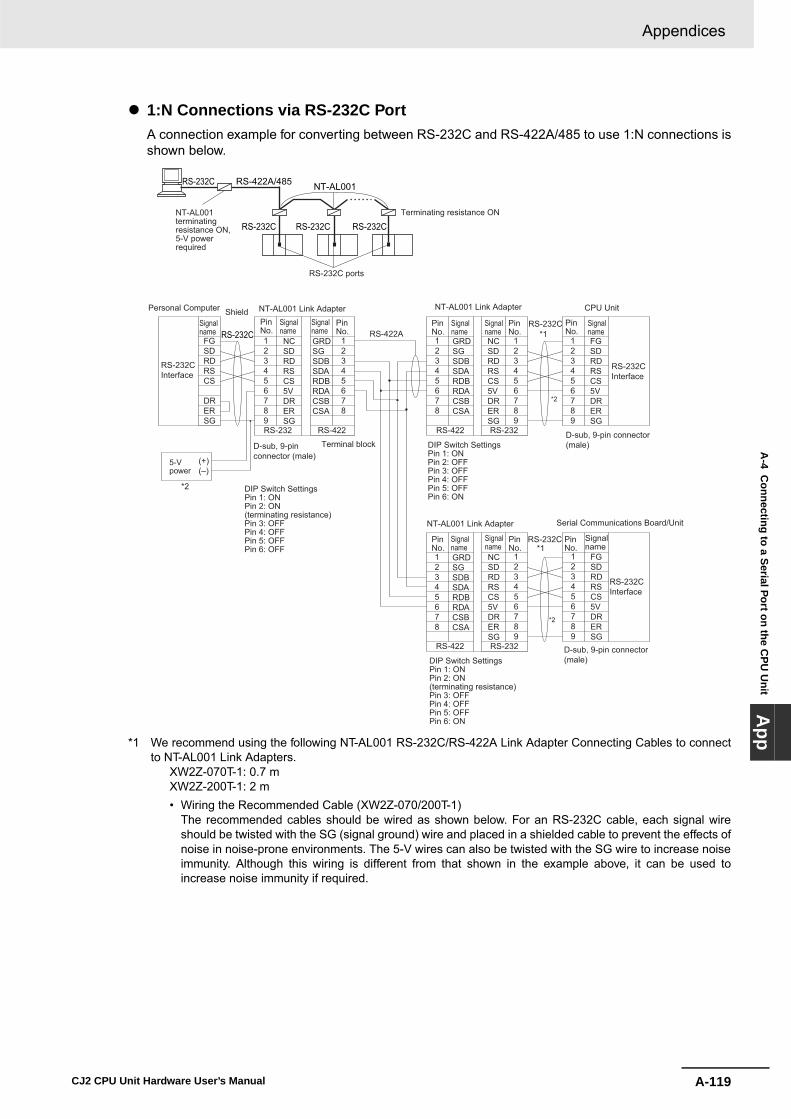
A-119
Appendices
CJ2 CPU Unit Hardware User’s Manual
A-4 C
onnecting to a Serial Port on the CPU
Unit
App
� 1:N Connections via RS-232C PortA connection example for converting between RS-232C and RS-422A/485 to use 1:N connections isshown below.
*1 We recommend using the following NT-AL001 RS-232C/RS-422A Link Adapter Connecting Cables to connectto NT-AL001 Link Adapters.
XW2Z-070T-1: 0.7 mXW2Z-200T-1: 2 m• Wiring the Recommended Cable (XW2Z-070/200T-1)
The recommended cables should be wired as shown below. For an RS-232C cable, each signal wireshould be twisted with the SG (signal ground) wire and placed in a shielded cable to prevent the effects ofnoise in noise-prone environments. The 5-V wires can also be twisted with the SG wire to increase noiseimmunity. Although this wiring is different from that shown in the example above, it can be used toincrease noise immunity if required.
NT-AL001RS-422A/485RS-232C
RS-232C RS-232C RS-232CNT-AL001terminatingresistance ON, 5-V power required
Terminating resistance ON
RS-232C ports
RS-232C
RS-232C
Shield CPU Unit
*2
Personal Computer
Signalname
Signalname
Signalname
Signalname
Signalname
Signalname
Signalname
Signalname
Signalname
RS-232CInterface
NT-AL001 Link Adapter
D-sub, 9-pin connector (male)
DIP Switch SettingsPin 1: ONPin 2: ON(terminating resistance)Pin 3: OFFPin 4: OFFPin 5: OFFPin 6: OFF
DIP Switch SettingsPin 1: ONPin 2: OFFPin 3: OFFPin 4: OFFPin 5: OFFPin 6: ON
D-sub, 9-pin connector (male)
RS-232CInterface
RS-232CInterface
*1
*2
D-sub, 9-pin connector (male)
Serial Communications Board/Unit NT-AL001 Link Adapter
DIP Switch SettingsPin 1: ONPin 2: ON(terminating resistance)Pin 3: OFFPin 4: OFFPin 5: OFFPin 6: ON
NT-AL001 Link Adapter
PinNo.
PinNo.
PinNo.
PinNo.
PinNo.
PinNo.
PinNo.
PinNo.
RS-232C
Terminal block
FGSDRDRSCS
DRERSG
123456789
12345678
12345678
123456789
123456789
RS-422A
*1
*2
NCSDRDRSCS5VDRERSG
NCSDRDRSCS5VDRERSG
GRDSGSDBSDARDBRDACSBCSA
GRDSGSDBSDARDBRDACSBCSA
FGSDRDRSCS5VDRERSG
RS-232 RS-422 RS-422 RS-232
12345678
GRDSGSDBSDARDBRDACSBCSA
RS-422
123456789
NCSDRDRSCS5VDRERSGRS-232
123456789
FGSDRDRSCS5VDRERSG
5-Vpower
(+)(–)

Appendices
A-120 CJ2 CPU Unit Hardware User’s Manual
Wiring with XW2Z-@@0T-1 (10 conductors)
*2 When the NT-AL001 Link Adapter is connected to the RS-232C port on the CPU Unit, 5 V is supplied from pin6, eliminating the need for a 5-V power supply.
Precautions for Correct UsePrecautions for Correct Use
• Do not use the 5-V power from pin 6 of the RS-232C port for anything but the NT-AL001 LinkAdapter, CJ1W-CIF11 RS-422A Converter, or NV3W-M@20L Programmable Terminals. Usingthis power supply for any other external device may damage the CPU Unit or the externaldevice.
• The XW1Z-@@0T-1 Cable is designed to connect the NT-AL001 and contains special wiring forthe CS and RS signals. Do not use this cable for any other application. Connecting this cableto other devices can damage them.
DIP Switch Settings on the NT-AL001 Link Adapter
There is a DIP switch on the NT-AL001 Link Adapter that is used to set RS-422A/485 communicationsparameters. Set the DIP switch as required for the serial communications mode according to the follow-ing table.
Pin Function Default setting1 Not used. (Leave set to ON.) ON
2 Internal terminating resistance setting.ON: Terminating resistance connected.OFF: Terminating resistance not connected.
ON
3 2-wire/4-wire settingBoth pins ON: 2-wire communicationsBoth pins OFF: 4-wire communications
OFF
4 OFF
5 Communications modeBoth pins OFF: Always send.5 OFF/6 ON: Send when RS-232C's CS is high.5 ON/6 OFF: Send when RS-232C's CS is low.
ON
6 OFF
Shell
Notused.
ShieldShell
Signalname
Signalname
Internal signalsArrows indicate signal directions
Returned
Returned
PinNo.
PinNo.
PLC NT-AL001
123456789
FGSDRDRSCS5VDRERSGFG
132456789
RDSDRSCS5VDRERSGFG
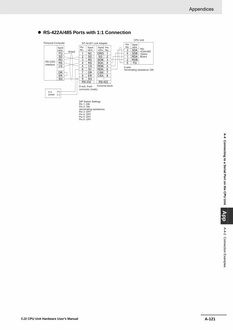
A-121
Appendices
CJ2 CPU Unit Hardware User’s Manual
A-4 C
onnecting to a Serial Port on the CPU
Unit
App
A-4-2 C
onnection Exam
ples
� RS-422A/485 Ports with 1:1 Connection
FGSDRDRSCS
DRERSG
123456789
NCSDRDRSCS5VDRERSG
12345678
RS-422RS-232
GRDSG
SDBSDARDBRDACSBCSA
34125
SDASDBRDARDBFG
Shield
CPU UnitPersonal Computer
Signalname
Signalname
SignalnameSignal
name
RS-232CInterface
NT-AL001 Link Adapter
D-sub, 9-pin connector (male)
DIP Switch SettingsPin 1: ONPin 2: ON(terminating resistance)Pin 3: OFFPin 4: OFFPin 5: OFFPin 6: OFF
PinNo.
PinNo.Pin
No.
Terminal block
5-Vpower
(+)(–)
RS-422A/485OptionBoard
4-wireTerminating resistance: ON
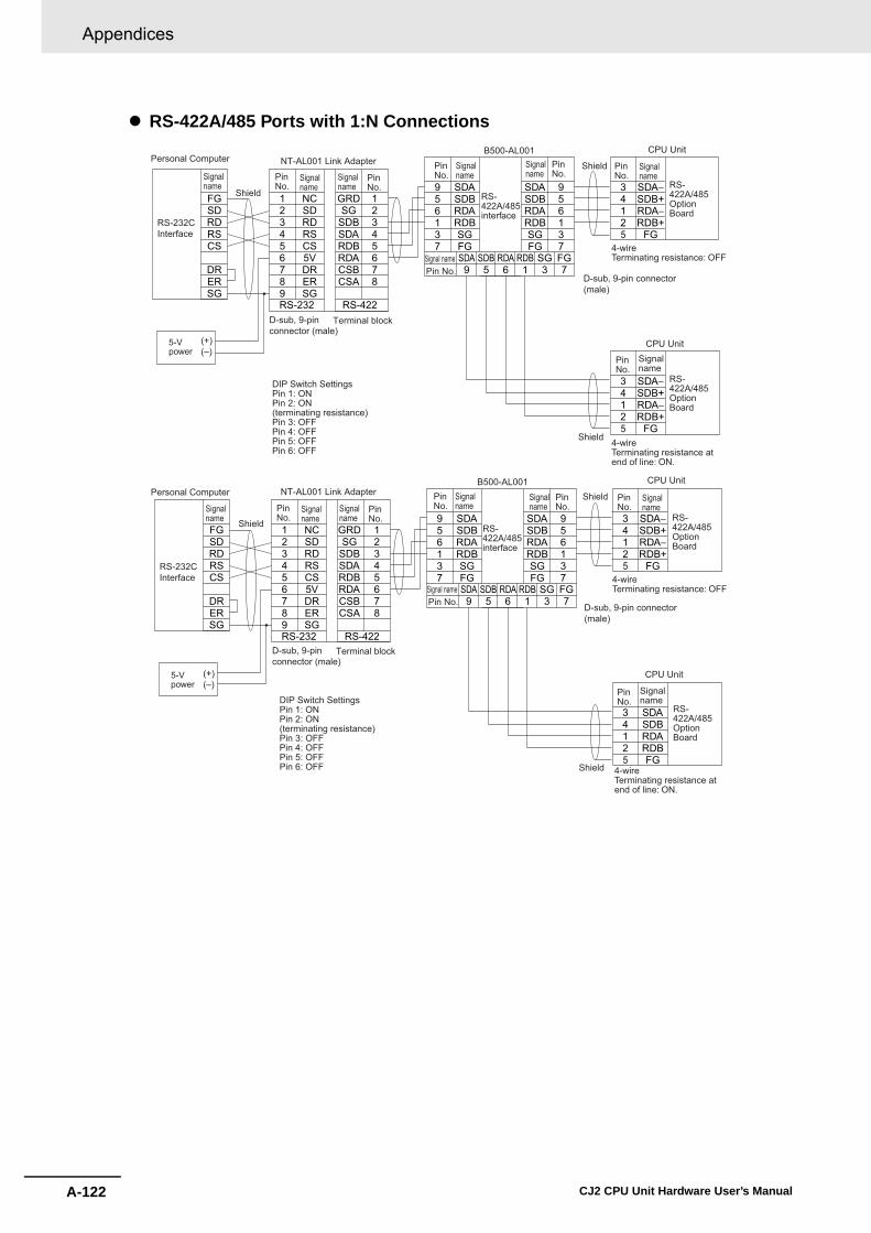
Appendices
A-122 CJ2 CPU Unit Hardware User’s Manual
� RS-422A/485 Ports with 1:N Connections
FGSDRDRSCS
DRERSG
123456789
NCSDRDRSCS5VDRERSG
12345678
RS-422RS-232
GRDSG
SDBSDARDBRDACSBCSA
956137
SDASDBRDARDBSGFG
956137
SDA9
SDB5
RDA6
RDB1
SG3
FG7
SDASDBRDARDBSGFG
34125
SDA−SDB+RDA−RDB+
FG
34125
SDA−SDB+RDA−RDB+
FG
Shield
CPU UnitPersonal Computer
Signalname
Signalname
Signalname
Signalname
Signalname
SignalnameSignal
name
RS-232CInterface
NT-AL001 Link Adapter
D-sub, 9-pin connector (male)
DIP Switch SettingsPin 1: ONPin 2: ON(terminating resistance)Pin 3: OFFPin 4: OFFPin 5: OFFPin 6: OFF
D-sub, 9-pin connector (male)
PinNo.
PinNo.
PinNo.
PinNo.
PinNo.Pin
No.
Terminal block
5-Vpower
(+)(–)
Signal namePin No.
Shield
CPU Unit
Shield
B500-AL001
RS-422A/485interface
RS-422A/485OptionBoard
4-wireTerminating resistance: OFF
RS-422A/485OptionBoard
4-wireTerminating resistance at end of line: ON.
FGSDRDRSCS
DRERSG
123456789
NCSDRDRSCS5VDRERSG
12345678
RS-422RS-232
GRDSG
SDBSDARDBRDACSBCSA
956137
SDASDBRDARDBSGFG
956137
SDA9
SDB5
RDA6
RDB1
SG3
FG7
SDASDBRDARDBSGFG
34125
SDA−SDB+RDA−RDB+
FG
34125
SDASDBRDARDBFG
Shield
CPU UnitPersonal Computer
Signalname
Signalname
Signalname
Signalname
Signalname
SignalnameSignal
name
RS-232CInterface
NT-AL001 Link Adapter
D-sub, 9-pin connector (male)
DIP Switch SettingsPin 1: ONPin 2: ON(terminating resistance)Pin 3: OFFPin 4: OFFPin 5: OFFPin 6: OFF
D-sub, 9-pin connector (male)
PinNo.
PinNo.
PinNo.
PinNo.
PinNo.Pin
No.
Terminal block
5-Vpower
(+)(–)
Signal namePin No.
Shield
CPU Unit
Shield
B500-AL001
RS-422A/485interface
RS-422A/485OptionBoard
4-wireTerminating resistance: OFF
RS-422A/485OptionBoard
4-wireTerminating resistance at end of line: ON.

A-123
Appendices
CJ2 CPU Unit Hardware User’s Manual
A-4 C
onnecting to a Serial Port on the CPU
Unit
App
A-4-2 C
onnection Exam
ples
� Direct Connection from RS-232C to RS-232C
• Communications Mode: Host Link (unit number 0 only for Host Link)NT Link (1:N, N = 1 Unit only)
• OMRON Cables with Connectors:XW2Z-200T-1: 2 mXW2Z-500T-1: 5 m
� RS-422A/485 Ports with 1:1 Connection
• Communications Mode: Host Link (Host Link unit number 0 only)NT Link (1:N, N = 1 Unit only)
* Switch Settings on RS-422A/485 Option Board• Terminating resistance: ON• 2-wire/4-wire setting: 4-wire
Note The terminating resistance setting example is for the NT631/NT631C. The setting method depends on the PT model. Refer to the manual for your PT.
OMRON PT (Host Link or 1:N NT Link)
RS-232C
PT
Host Link or NT Link (1:N)
RS-232C port
–
––
CPU Unit PT
HoodHood
Signalname
Signalname
RS-232CInterface
RS-232CInterface
D-sub, 9-pin connector (male) D-sub, 9-pin
connector (male)
PinNo.
PinNo.
FGFGSDRDRSCS5VDRERSG
123456789
123456789
FG
SDRDRSCS5V
SG
RDATRMRDBSDASDBRSARSB
34125
SDA−SDB+RDA−RDB+FG
CPU Unit
Signalname
Signal namePinNo.
Terminal block
RS-422A/485OptionBoard
Short pinPT (See note.)
RS-422A/485interface
Functional ground
Terminal block/D-sub connector
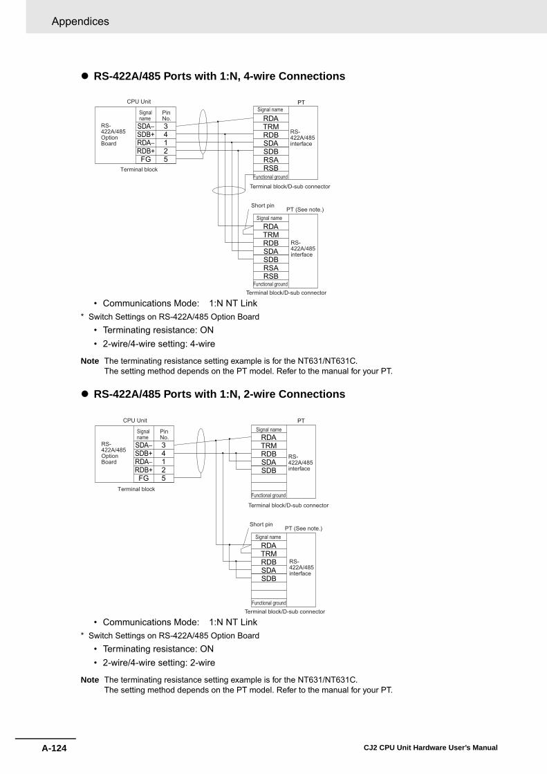
Appendices
A-124 CJ2 CPU Unit Hardware User’s Manual
� RS-422A/485 Ports with 1:N, 4-wire Connections
• Communications Mode: 1:N NT Link* Switch Settings on RS-422A/485 Option Board
• Terminating resistance: ON• 2-wire/4-wire setting: 4-wire
Note The terminating resistance setting example is for the NT631/NT631C. The setting method depends on the PT model. Refer to the manual for your PT.
� RS-422A/485 Ports with 1:N, 2-wire Connections
• Communications Mode: 1:N NT Link* Switch Settings on RS-422A/485 Option Board
• Terminating resistance: ON• 2-wire/4-wire setting: 2-wire
Note The terminating resistance setting example is for the NT631/NT631C. The setting method depends on the PT model. Refer to the manual for your PT.
PT
RDATRMRDBSDASDBRSARSB
34125
SDA−SDB+RDA−RDB+FG
RDATRMRDBSDASDBRSARSB
CPU Unit
Signalname
Signal namePinNo.
Terminal block
Signal name
RS-422A/485OptionBoard
Short pinPT (See note.)
RS-422A/485interface
Terminal block/D-sub connector
RS-422A/485interface
Terminal block/D-sub connector
Functional ground
Functional ground
RDATRMRDBSDASDB
34125
SDA−SDB+RDA−RDB+FG
RDATRMRDBSDASDB
CPU Unit
Signalname
Signal namePinNo.
Terminal block
Signal name
PT
RS-422A/485OptionBoard
Short pinPT (See note.)
RS-422A/485interface
Terminal block/D-sub connector
RS-422A/485interface
Terminal block/D-sub connector
Functional ground
Functional ground
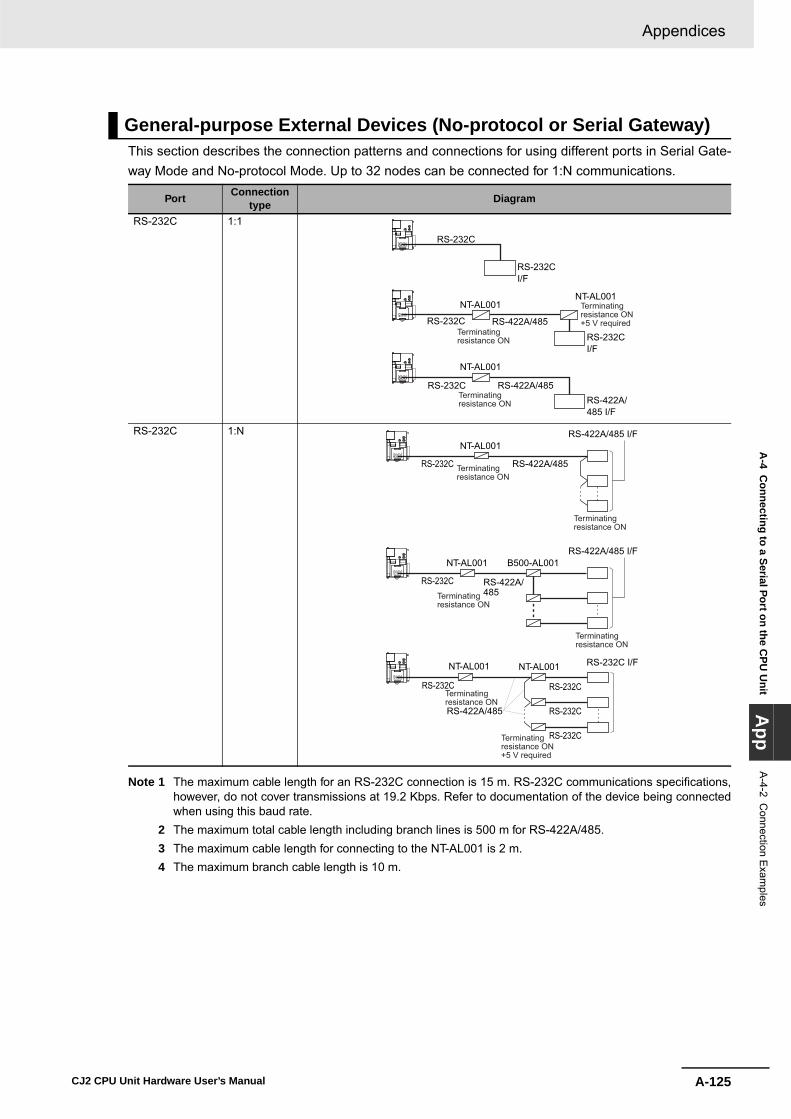
A-125
Appendices
CJ2 CPU Unit Hardware User’s Manual
A-4 C
onnecting to a Serial Port on the CPU
Unit
App
A-4-2 C
onnection Exam
ples
This section describes the connection patterns and connections for using different ports in Serial Gate-way Mode and No-protocol Mode. Up to 32 nodes can be connected for 1:N communications.
Note 1 The maximum cable length for an RS-232C connection is 15 m. RS-232C communications specifications,however, do not cover transmissions at 19.2 Kbps. Refer to documentation of the device being connectedwhen using this baud rate.
2 The maximum total cable length including branch lines is 500 m for RS-422A/485. 3 The maximum cable length for connecting to the NT-AL001 is 2 m. 4 The maximum branch cable length is 10 m.
General-purpose External Devices (No-protocol or Serial Gateway)
Port Connection type Diagram
RS-232C 1:1
RS-232C 1:N
RS-232CI/F
RS-232C
NT-AL001
NT-AL001
NT-AL001
RS-232CI/F
RS-422A/485RS-232C
RS-422A/485 I/F
RS-422A/485RS-232C
Terminating resistance ON+5 V required
Terminating resistance ON
Terminating resistance ON
RS-422A/485 I/FNT-AL001
RS-232C RS-422A/485
NT-AL001
RS-232C RS-422A/485
B500-AL001
NT-AL001
RS-232C RS-232C
RS-232C
RS-232C
RS-422A/485
NT-AL001
RS-422A/485 I/F
RS-232C I/F
Terminating resistance ON+5 V required
Terminating resistance ON
Terminating resistance ON
Terminating resistance ON
Terminating resistance ON
Terminating resistance ON

Appendices
A-126 CJ2 CPU Unit Hardware User’s Manual
Note 1 The maximum cable length for an RS-232C connection is 15 m. RS-232C communications specifications,however, do not cover transmissions at 19.2 Kbps. Refer to documentation of the device being connectedwhen using this baud rate.
2 The CP1W-CIF11 RS-422A/485 Option Board is not isolated. The maximum transmission distance istherefore 50 m. If the distance exceeds 50 m, use the isolated CP1W-CIF12, or connect the isolated NT-AL001 RS-422A Link Adapter to the RS-232C port on the CP1W-CIF01 RS-232C Option Board. If you useone of these methods, the maximum total transmission distance will be 500 m.
3 The maximum cable length for connecting to the NT-AL001 is 2 m. 4 The maximum branch cable length is 10 m.
� Examples of 1:1 Connections to RS-232C PortsConnecting to E5CK Temperature Controllers
Port Connection type Diagram
RS-422A/485 1:1
RS-422A/485 1:N
NT-AL001
RS-422A/485
RS-422A/485
RS-422A/485 I/F
RS-232C I/FRS-232C
Terminating resistance ON+5 V required
RS-422A/485 I/F
RS-422A/485
RS-422A/485
B500-AL001
RS-232C
RS-232C
RS-232C
RS-422A/485
NT-AL001
RS-422A/485 I/F
RS-232C I/F
Terminating resistance ON+5 V required
Terminating resistance ON
Terminating resistance ON
Terminating resistance ON
Terminating resistance ON
Terminating resistance ON
12345789
FGSDRDRSCSDRERSG
13141
SDRDSG
Signal name
D-sub, 9-pin connector (male)
Pin No.Signal name
CPU UnitRS-232C Option Board
RS-232Cshield
Example: E5CK (OMRON Temperature Controller)
RS-232C: Terminal blockTerminal

A-127
Appendices
CJ2 CPU Unit Hardware User’s Manual
A-4 C
onnecting to a Serial Port on the CPU
Unit
App
A-4-2 C
onnection Exam
ples
Using an NT-AL-001 RS-232C/RS-422A Link Adapter
*1 We recommend using the following NT-AL001 Link Adapter Connecting Cables to connect to NT-AL001 LinkAdapters.
Connecting to Modems
NT-AL001 Connecting Cables: XW2Z-070T-1 (0.7 m)XW2Z-200T-1 (2 m)
RS-232C
RS-422A RS-232CFGSDRDRSCS
DRERSG
123456789
NCSDRDRSCS5VDRERSG
12345678
RS-422RS-232
GRDSG
SDBSDARDBRDACSBCSA
123456789
FGSDRDRSCS5VDRERSG
12345678
GRDSG
SDBSDARDBRDACSBCSA
123456789
RS-232RS-422
NCSDRDRSCS5VDRERSG
Shield
CPU Unit
*1
Personal Computer
Signalname
Signalname
Signalname
Signalname
Signalname
Signalname
RS-232CInterface
NT-AL001 Link Adapter
D-sub, 9-pin connector (male)
DIP Switch SettingsPin 1: ONPin 2: ON (terminating resistance)Pin 3: OFF (4-wire)Pin 4: OFF (4-wire)Pin 5: OFFPin 6: ON
NT-AL001 Link Adapter
PinNo.
PinNo.
PinNo.
PinNo.
PinNo.
Terminal block
5-Vpower
(+)(–)
D-sub, 9-pin connector (male)
RS-232COptionBoard
DIP Switch SettingsPin 1: ONPin 2: ON (terminating resistance)Pin 3: OFF (4-wire)Pin 4: OFF (4-wire)Pin 5: OFFPin 6: OFF
123456789
10111213141516171819202122232425
ModemFGSDRDRSCSDRSGCD
ST2
RT
ER
CI
ST1
123456789
FGSDRDRSCS5VDRERSG
CPU Unit RS-232COption Board

Appendices
A-128 CJ2 CPU Unit Hardware User’s Manual
� Examples of 1:N Connections to RS-232C Ports
*1 We recommend using the following NT-AL001 Link Adapter Connecting Cables to connect to NT-AL001 LinkAdapters.
NT-AL001 Connecting Cables: XW2Z-070T-1 (0.7 m)XW2Z-200T-1 (2 m)
RS-422ARS-232C
123456789
NCSDRDRSCS5VDRERSG
12345678
RS-422RS-232
GRDSG
SDBSDARDBRDACSBCSA
SDASDBRDARDB
SDASDBRDARDB
123456789
FGSDRDRSCS5VDRERSG
Shield
CPU Unit
Signalname
Signalname
Signalname
Signalname
Signalname
NT-AL001 Link Adapter
D-sub, 9-pin connector (male)
DIP Switch SettingsPin 1: ONPin 2: ON (terminating resistance)Pin 3: OFF (4-wire)Pin 4: OFF (4-wire)Pin 5: OFFPin 6: OFF
D-sub, 9-pin connector (male)
*1
PinNo.
PinNo.
PinNo.
Terminal block
Shield
RS-232COptionBoard
ComponentwithRS-422A/485(4-wire)
RS-422A/485interface
RS-422A/485interface
ComponentwithRS-422A/485(4-wire)
123456789
NCSDRDRSCS5VDRERSG
12345678
RS-422RS-232
GRDSG
SDBSDARDBRDACSBCSA
123456789
FGSDRDRSCS5VDRERSG
CPU UnitSignalname
Signalname
Signalname
Signalname
Signalname
NT-AL001 Link Adapter
D-sub, 9-pin connector (male)
D-sub, 9-pin connector (male)
*1
PinNo.
PinNo.
PinNo.
Terminal block
ShieldA(−)B(+)
A(−)B(+)
DIP Switch SettingsPin 1: ONPin 2: ON (terminating resistance)Pin 3: ON (2-wire)Pin 4: ON (2-wire)Pin 5: OFFPin 6: ON
RS-232COptionBoard
ComponentwithRS-422A/485(2-wire)
RS-422A/485interface
RS-422A/485interface
ComponentwithRS-422A/485(2-wire)

A-129
Appendices
CJ2 CPU Unit Hardware User’s Manual
A-4 C
onnecting to a Serial Port on the CPU
Unit
App
A-4-2 C
onnection Exam
ples
� Examples of 1:1 Connections to RS-422A/485 Ports
34125
SDA−SDB+RDA−RDB+FG
SDASDBRDARDB
34125
SDA−SDB+RDA−RDB+FG
CPU Unit
Signalname
Signalname
Signalname
Signalname
PinNo.
PinNo.
Terminal block
ShieldA(−)B(+)
Terminal block
CPU Unit
Shield
ComponentwithRS-422A/485(4-wire)
RS-422A/485interface
RS-422A/485interface
ComponentwithRS-422A/485(2-wire)
RS-422A/485OptionBoard
RS-422A/485OptionBoard
34125
SDA−SDB+RDA−RDB+FG
FGSDRDRSCS
DRERSG
RS-422A
RS-232C12345678
GRDSG
SDBSDARDBRDACSBCSA
123456789
RS-232RS-422
NCSDRDRSCS5VDRERSG
CPU Unit
Signalname Signal
nameSignalname
Signalname
NT-AL001 Link Adapter
DIP Switch SettingsPin 1: ONPin 2: ON(terminating resistance)Pin 3: OFFPin 4: OFFPin 5: OFFPin 6: OFF
D-sub, 9-pin connector (male)
PinNo. Pin
No.PinNo.
Terminal block
ShieldPersonal Computer
5-Vpower
(+)(–)
RS-232CInterface
RS-422A/485OptionBoard

Appendices
A-130 CJ2 CPU Unit Hardware User’s Manual
� Examples of 1:N Connections to RS-422A/485 Ports
34125
SDA−SDB+RDA−RDB+FG
Signalname
PinNo.
Terminal block
CPU Unit
SignalnameA(−)B(+)
SignalnameA(−)B(+)
RS-422A/485interface
ComponentwithRS-422A/485(2-wire)
RS-422A/485interface
ComponentwithRS-422A/485(2-wire)
RS-422A/485OptionBoard
34125
SDA−SDB+RDA−RDB+FG
B500-AL001RS-422A
RS-422A
RS-422A
956137
SDASDBRDARDBSGFG
956137
SDA9
SDB5
RDA6
RDB1
SG3
FG7
SDASDBRDARDBSGFG
SDASDBRDARDB
SDASDBRDARDB
CPU UnitSignalname
Signalname
Signalname
Signalname
D-sub, 9-pin connector (male)
PinNo.
PinNo.
PinNo.
Terminal block
Shield
Shield
ShieldSignalname
Signal namePin No.
RS-422A/485interface
ComponentwithRS-422A/485(4-wire)
RS-422Ainterface
RS-422A/485OptionBoard
ComponentwithRS-422A/485(4-wire)
RS-422A/485interface

A-131
Appendices
CJ2 CPU Unit Hardware User’s Manual
A-4 C
onnecting to a Serial Port on the CPU
Unit
App
A-4-2 C
onnection Exam
ples
Examples of connections to use Serial PLC Links are provided below. The Serial PLC Link communica-tions mode is used.
� Connecting with RS-422A Converters
Note The CP1W-CIF11 is not isolated. The maximum transmission distance is therefore 50 m.If the distance exceeds 50 m, use the isolated CP1W-CIF12, or the NT-AL001. Do not use the CJ1W-CIF11 in the transmission path. If you use the NT-AL001 and CP1W-CIF12, the maxi-mum total transmission distance will be 500 m.
Serial PLC Links for OMRON CJ2M, CJ1M, CP1H, CP1L, and CP1EPLCs
34125
SDA−SDB+RDA−RDB+FG
RS-232C
RS-232C
RS-422AFGSDRDRSCS
DRERSG
12345678
GRDSG
SDBSDARDBRDACSBCSA
123456789
RS-232RS-422
NCSDRDRSCS5VDRERSG
FGSDRDRSCS
DRERSG
12345678
GRDSG
SDBSDARDBRDACSBCSA
123456789
RS-232RS-422
NCSDRDRSCS5VDRERSG
Shield
CPU Unit
Signalname
Signalname
Signalname
Signalname
Signalname
Signalname
Signalname
D-sub, 9-pin connector (male)
DIP Switch SettingsPin 1: ONPin 2: ON(terminating resistance)Pin 3: OFFPin 4: OFFPin 5: OFFPin 6: ON
D-sub, 9-pin connector (male)
RS-232CInterface
NT-AL001 Link Adapter
NT-AL001 Link Adapter
PinNo.
PinNo.
PinNo.
PinNo.
PinNo.
Terminal block
5-Vpower
(+)(–)
Shield
RS-232CInterface
Shield
Terminal block5-Vpower
(+)(–)
Shield
RS-422A/485OptionBoard
4-wireTerminating resistance: ON
Terminal blockDIP Switch: Pin 2: OFF (terminating resistance); Other pins are the same as below.
CJ2M CPU Unit (Polling Unit) CJ2M CPU Unit (Polled Unit 0)
CJ1W-CIF11 RS-422A Converter
RS-422A/485Option Board
Serial PLC Link (maximum total distance: 50 m)
CJ1M CPU Unit (Polled Unit 1)
RS-232C port built into CPU Unit
CJ1W-CIF11 RS-422A Converter

Appendices
A-132 CJ2 CPU Unit Hardware User’s Manual
� Connections to RS-232C PortsRS-232C can also be used to connect two CJ2M CPU Units with a Serial PLC Link.
� Connection Example
FG 1 SD 2 RD 3 RS 4 CS 5 5V 6 DR 7 ER 8 SG 9
1 FG 2 SD 3 RD 4 RS 5 CS 6 5V 7 DR 8 ER 9 SG
CJ2M CPU Unit RS-232C Option Board
RS
-232
C
RS
-232
C
CJ2M CPU Unit RS-232C Option Board
Signal name Pin No. Signal namePin No.
CJ2M CPU Unit (Polling Unit)RS-232C Option Board CP1W-CIF01CJ1W-CIF11 DIP SW SW1: ON (terminating resistance ON) SW2: OFF (4-wire) SW3: OFF (4-wire) SW4: OFF SW5: OFF (no RS control for RD) SW6: OFF (no RS control for SD)
RS-422A/485 interface
Shield
PinNo.
PinNo.
Sig
nal
nam
e
Sig
nal
nam
e
PinNo.
Sig
nal
nam
e
RS-422A/485 interface RS-422A/485 interface
CJ2M CPU Unit (Polled Unit 0)RS-422A/485 Option Board CP1W-CIF11/CIF12 DIP SW SW1: ON (terminating resistance OFF) SW2: OFF (4-wire) SW3: OFF (4-wire) SW4: OFF SW5: OFF (no RS control for RD) SW6: ON (RS control for SD)
CJ1M CPU Unit (Polled Unit 1)
CJ1W-CIF11 DIP SW SW1: ON (terminating resistance ON) SW2: OFF (4-wire) SW3: OFF (4-wire) SW4: OFF SW5: OFF (no RS control for RD) SW6: ON (RS control for SD)
RD
A
RD
B
SD
A
SD
B
FG
1 2 3 4 5
RD
A
RD
B
SD
A
SD
B
FG
1 2 3 4 5
RD
A
RD
B
SD
A
SD
B
FG
1 2 3 4 5
CJ2M CPU Unit (Polling Unit)RS-232C Option Board CP1W-CIF01CP1W-CIF11 DIP SW SW1: ON (terminating resistance ON) SW2: ON (2-wire) SW3: ON (2-wire) SW4: OFF SW5: OFF (no RS control for RD) SW6: ON (RS control for SD)
RS-422A/485 interface
Shield
PinNo.
PinNo.
Sig
nal
nam
e
Sig
nal
nam
e
PinNo.
Sig
nal
nam
e
RS-422A/485 interface RS-422A/485 interface
CJ2M CPU Unit (Polled Unit 0)RS-422A/485 Option Board CP1W-CIF11/CIF12 DIP SW SW1: OFF (terminating resistance OFF) SW2: ON (2-wire) SW3: ON (2-wire) SW4: OFF SW5: OFF (no RS control for RD) SW6: ON (RS control for SD)
CJ1M CPU Unit (Polled Unit 1)
CJ1W-CIF11 DIP SW SW1: ON (terminating resistance ON) SW2: ON (2-wire) SW3: ON (2-wire) SW4: OFF SW5: OFF (no RS control for RD) SW6: ON (RS control for SD)

A-133
Appendices
CJ2 CPU Unit Hardware User’s Manual
A-4 C
onnecting to a Serial Port on the CPU
Unit
App
A-4-3 A
pplicable Connectors and R
ecomm
ended C
ables
� Connections for Echoback Test
We recommend the following wiring methods for RS-232C, especially in environment prone to noise.• Use shielded twisted-pair cable for communications cables. • Use a twisted-pair cable for each signal line and SG (signal ground) to connect the CPU Unit to a
communications partner. Also, bundle all the SG lines at the Unit and at the other device and connectthem together.
• Connect the shield line of the communications cable to the hood (FG) of the RS-232C connector atthe Unit. Also, ground the protective earth (GR) terminal of the Power Supply Units on the CPU Rackand the CJ-series Expansion Racks to a resistance of 100 Ω or less. The following example showsconnecting SD-SG, RD-SG, RS-SG, and CS-SG for Serial Communications Mode using a twisted-pair cable using the peripheral bus.
Note The hood (FG) is internally connected to the protective earth (GR) terminal on the Power Supply Unitthrough the CPU Rack. FG can thus be connected by connecting the protective earth (GR) terminal on thePower Supply Unit. The hood (FG) is also electrically connected to pin 1 (FG), but the connection resistancebetween the shield and the FG is smaller for the hood. To reduce contact resistance between the hood (FG)and the FG, connect the shield both to the hood (FG) and to pin 1 (FG).
Use the following connections.
A-4-3 Applicable Connectors and Recommended Cables
Examples of Recommended RS-232C Wiring
Example for CJ2H CPU Unit Example for CJ2M CPU Unit
RS-232C portSignal name
SDRDRSCSFGERDR
Pin No.2345187
RS-422A/485 portSignal name
SDA-SDB+RDA-RDB+
FG
Pin No.34125
XM2S-0911-EHoodShield
SG signal lineCPU Unit External device
Signalname
PinNo.
Signalname
SG signal lines bundled together
Aluminum foil23459
1
SDRDRSCSSGFGFG
RDSDCSRSSGFG
GR
CPU UnitPower Supply Unit
Ground to 100 Ωor less
Hood and GR connected internally.The hood will be grounded if the GR terminal is grounded.
POWER
PA205R
DC24VAC240V
OUTPUTRUN
INPUTAC100-240V
L2/N
L1
COMM
GR
Power Supply Unit
Ground to 100 Ωor less

Appendices
A-134 CJ2 CPU Unit Hardware User’s Manual
� Applicable Connector and Recommended CablesUse the following connectors and cables when making an RS-232C cable to connect to the RS-232Cport.
Applicable Connectors
CPU Unit Connector
Personal Computer Connector for IBM PC/AT Computer (9-pin Male Connector)
Recommended Cables
We recommend using the following shielded twisted-pair cables to provide noise resistance.
Fujikura Ltd.: UL2464 AWG28 × 5P IFS-RVV-SB (UL product)AWG 28 × 5P IFVV-SB (non-UL product)
Hitachi Cable, Ltd.: UL2464-SB(MA) 5P × 28AWG (7/0.127) (UL product)CO-MA-VV-SB 5P × 28AWG (7/0.127) (non-UL product)
Precautions for Correct UsePrecautions for Correct Use
Use the special cables provided from OMRON for all connections whenever possible. If cablesare produced in-house, be sure they are wired correctly. External devices and the CPU Unit maybe damaged if general purpose (e.g., computer to modem) cables are used or if wiring is not cor-rect.
Item Model SpecificationsPlug XM2A-0901 9-pin male Used together (One of each pro-
vided with CPU Unit.)Hood XM2S-0911-E 9-pin, millimeter screws, static-resistant
Item Model SpecificationsPlug XM2A-0901 9-pin female Used together
Hood XM2S-0913 9-pin, inch screws, static-resistant
IBM PC/AT or compatible
Computer(9-pin male connector)
Plug:XM2D-0901(9-pin female)
CPU Unit
RS-232Cport
Hood: XM2S-0913Recommended cable Hood: XM2S-0911-E Plug: XM2A-0901
Provided with the CPU Unit
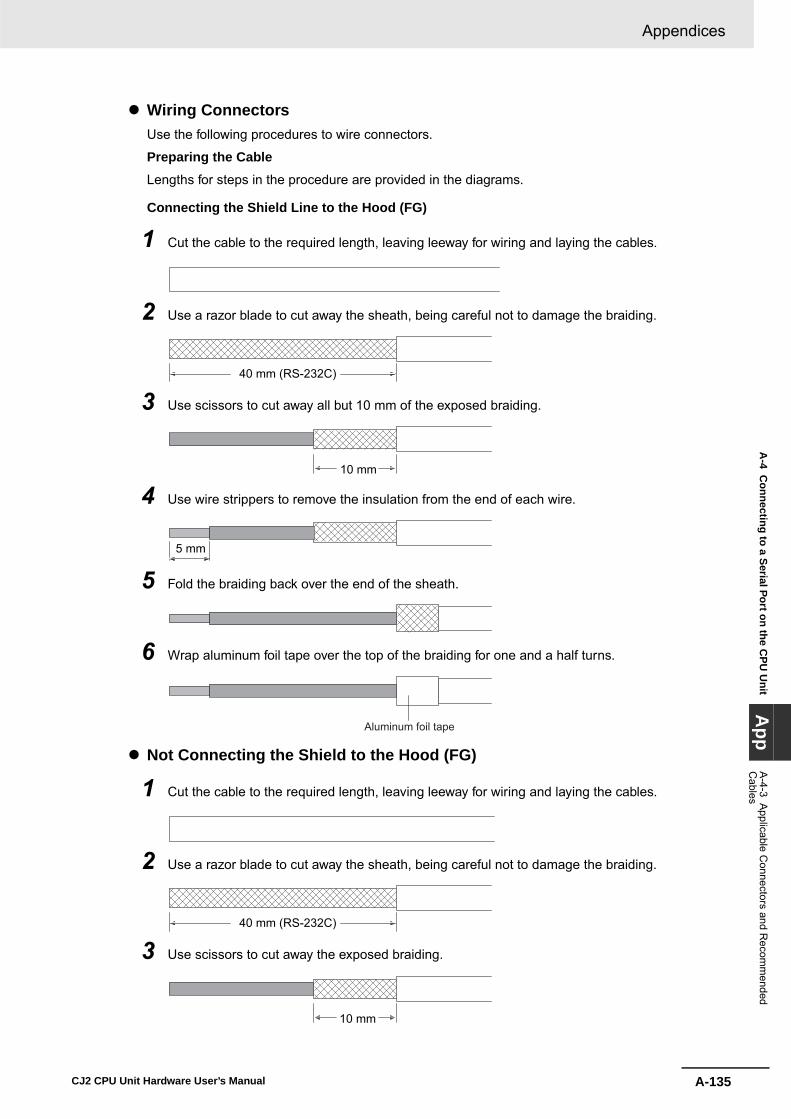
A-135
Appendices
CJ2 CPU Unit Hardware User’s Manual
A-4 C
onnecting to a Serial Port on the CPU
Unit
App
A-4-3 A
pplicable Connectors and R
ecomm
ended C
ables
� Wiring ConnectorsUse the following procedures to wire connectors.
Preparing the Cable
Lengths for steps in the procedure are provided in the diagrams.
Connecting the Shield Line to the Hood (FG)
1 Cut the cable to the required length, leaving leeway for wiring and laying the cables.
2 Use a razor blade to cut away the sheath, being careful not to damage the braiding.
3 Use scissors to cut away all but 10 mm of the exposed braiding.
4 Use wire strippers to remove the insulation from the end of each wire.
5 Fold the braiding back over the end of the sheath.
6 Wrap aluminum foil tape over the top of the braiding for one and a half turns.
� Not Connecting the Shield to the Hood (FG)
1 Cut the cable to the required length, leaving leeway for wiring and laying the cables.
2 Use a razor blade to cut away the sheath, being careful not to damage the braiding.
3 Use scissors to cut away the exposed braiding.
40 mm (RS-232C)
10 mm
5 mm
Aluminum foil tape
40 mm (RS-232C)
10 mm

Appendices
A-136 CJ2 CPU Unit Hardware User’s Manual
4 Use wire strippers to remove the insulation from the end of each wire.
5 Wrap electrician's tape over the top and end of the cut sheath.
� Soldering
1 Place heat-shrinking tubes over all wires.
2 Pre-solder all wires and connector terminals.
3 Solder the wires.
4 Move the heat-shrinking tubes onto the soldered area and shrink them into place.
� Assembling the HoodAssemble the connector hood as shown.
5 mm
Electrician's tape
1 mm
Heat-shrinking tube (inner dia. 1.5, l = 10)
Soldering iron
Heat-shrinking tube
FG Connection
Ground plate
Aluminum foil tapeNo FG Connection

A-137
Appendices
CJ2 CPU Unit Hardware User’s Manual
A-4 C
onnecting to a Serial Port on the CPU
Unit
App
A-4-3 A
pplicable Connectors and R
ecomm
ended C
ables
� Connections to the CPU Unit• Always turn OFF the power supply to the PLC before connecting or disconnecting communica-
tions cables.• Tighten the communications connector attachment screws to 0.4 N·m.
We recommend using the following wiring for RS-422A/485 to ensure transmission quality.
1 Use shielded twisted-pair cable for communications cables.
• Recommended RS-422A/485 Cable
2 Connect the shield on the communications cable to the FG terminal on the RS-422A/485 OptionBoard. Also, ground the protective earth (GR) terminal on the CPU Unit to a resistance of 100 Ωor less.
Precautions for Correct UsePrecautions for Correct Use
Connect the shield on the communications cable to the FG terminal on the RS-422A/485 OptionBoard. Do not connect it on the other end of the cable. If you ground both ends, a difference inground potential may damage the equipment.
Example of Recommended RS-422A/485 Wiring
Model ManufacturerCO-HC-ESV-3P × 7/0.2 Hirakawa Hewtech Corp.
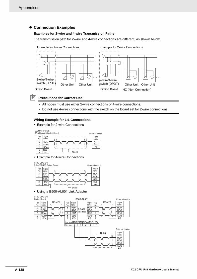
Appendices
A-138 CJ2 CPU Unit Hardware User’s Manual
� Connection ExamplesExamples for 2-wire and 4-wire Transmission Paths
The transmission path for 2-wire and 4-wire connections are different, as shown below.
Precautions for Correct UsePrecautions for Correct Use
• All nodes must use either 2-wire connections or 4-wire connections. • Do not use 4-wire connections with the switch on the Board set for 2-wire connections.
Wiring Example for 1:1 Connections• Example for 2-wire Connections
• Example for 4-wire Connections
• Using a B500-AL001 Link Adapter
NC (Non Connection)Option BoardOther Unit Other Unit Other Unit Other Unit
Example for 4-wire Connections Example for 2-wire Connections
2-wire/4-wireswitch (DPDT)
2-wire/4-wireswitch (DPDT)
Option Board
SDA−SDB+RDA−RDB+
FG
34125
FG
Signalname
PinNo.
SignalnameA(−)B(+)
Shield
CJ2M CPU Unit RS-422A/485 Option Board External device
SDA−SDB+RDA−RDB+
FG
34125
RDARDBSDASDBFG
Signalname
PinNo.
Signalname
Shield
CJ2M CPU Unit RS-422A/485 Option Board External device
SDA−SDB+RDA−RDB+
FG
34125
B500-AL001
61957
RDARDBSDASDBFG
61957
RDA6
RDB1
SDA9
SDB5
FG7
RDARDBSDASDBFG
RDARDBSDASDBFG
RS-422
RS-422
RDARDBSDASDBFG
RS-422Signalname
PinNo.
Signalname
Signalname
Signalname
Signalname
PinNo.
PinNo.
Signal namePin No.
RS-422Interface
CJ2M CPU Unit Option Board
External device
External device

A-139
Appendices
CJ2 CPU Unit Hardware User’s Manual
A-4 C
onnecting to a Serial Port on the CPU
Unit
App
A-4-3 A
pplicable Connectors and R
ecomm
ended C
ables
Take the following points into account when externally wiring communications cables.• When multi-conductor signal cable is being used, do not combine I/O wires and other control wires in
the same cable.• If wiring racks are parallel, allow at least 300 mm between them.
• If the I/O wiring and power cables must be placed in the same duct, they must be shielded from eachother using grounded steel sheet metal plates.
Noise Countermeasures for External Wiring
Communications cables
SYSMAC power supply lines and general control circuit lines
Power lines
Low-power cables
Control cables
Power cables
300 mm min.
300 mm min.
Ground to less than 100 Ω
200 mm min.
Communications cables
Power lines Steel sheet metal plates
Ground to less than 100 Ω
SYSMAC power supply lines and general control circuit lines
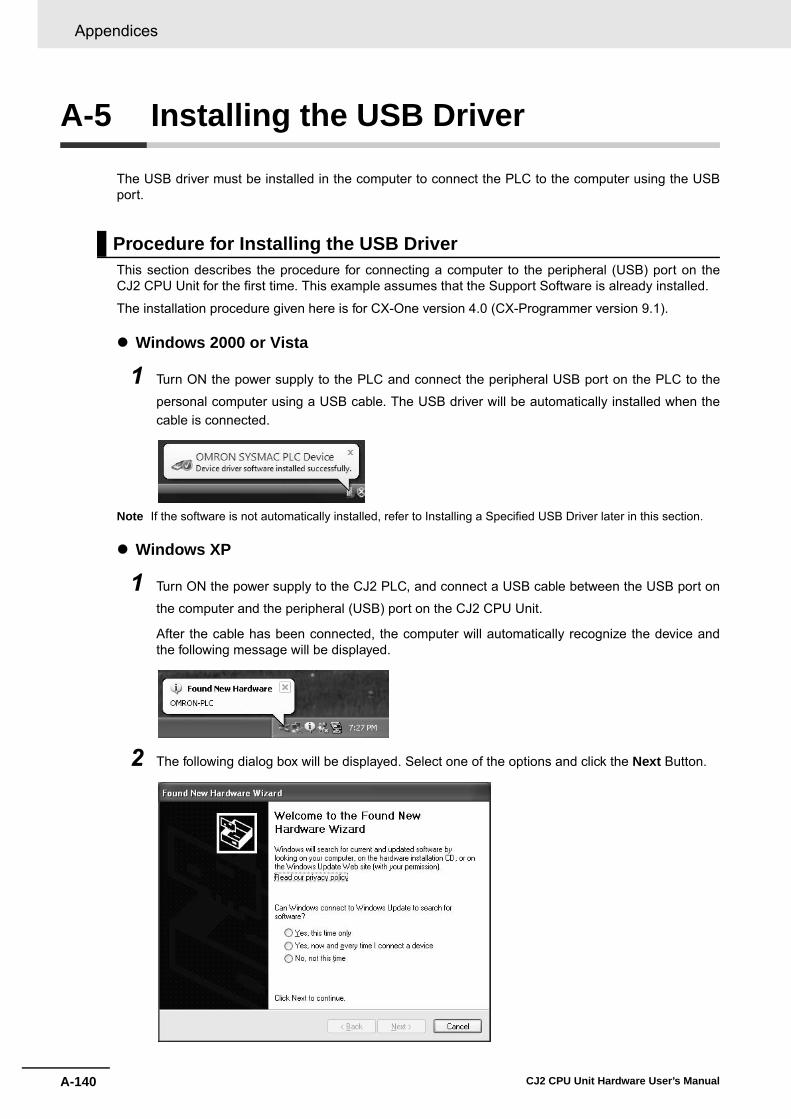
Appendices
A-140 CJ2 CPU Unit Hardware User’s Manual
A-5 Installing the USB Driver
The USB driver must be installed in the computer to connect the PLC to the computer using the USBport.
This section describes the procedure for connecting a computer to the peripheral (USB) port on theCJ2 CPU Unit for the first time. This example assumes that the Support Software is already installed.
The installation procedure given here is for CX-One version 4.0 (CX-Programmer version 9.1).
� Windows 2000 or Vista
1 Turn ON the power supply to the PLC and connect the peripheral USB port on the PLC to the
personal computer using a USB cable. The USB driver will be automatically installed when thecable is connected.
Note If the software is not automatically installed, refer to Installing a Specified USB Driver later in this section.
� Windows XP
1 Turn ON the power supply to the CJ2 PLC, and connect a USB cable between the USB port on
the computer and the peripheral (USB) port on the CJ2 CPU Unit.
After the cable has been connected, the computer will automatically recognize the device andthe following message will be displayed.
2 The following dialog box will be displayed. Select one of the options and click the Next Button.
Procedure for Installing the USB Driver

A-141
Appendices
CJ2 CPU Unit Hardware User’s Manual
A-5 Installing the U
SB D
riverA
ppA
-4-3 Applicable C
onnectors and Recom
mended
Cables
3 The following dialog box will be displayed. Select the Install the software automatically (Recom-mended) Option and click the Next Button.
Note 1 If the software cannot be installed automatically, refer to Installing a Specified USB Driver later in this sec-tion.
2 If the installation media is not inserted or the USB device driver is installed for another port, a Driver ListDialog Box will be displayed. Make sure that the newest driver is selected and click the Next Button.
4 Ignore the following dialog box if it is displayed and click the Continue Anyway Button.

Appendices
A-142 CJ2 CPU Unit Hardware User’s Manual
5 The following dialog box will be displayed if the installation is completed normally. Click the Fin-ish Button.
If the USB driver cannot be installed automatically, use the following procedure to install it.
� Windows Vista
1 Turn ON the power supply to the PLC and connect the peripheral USB port on the PLC to the
personal computer using a USB cable.
2 The following dialog box will be displayed. Select Locate and install driver software (Recom-mended).
Installing a Specified USB Driver
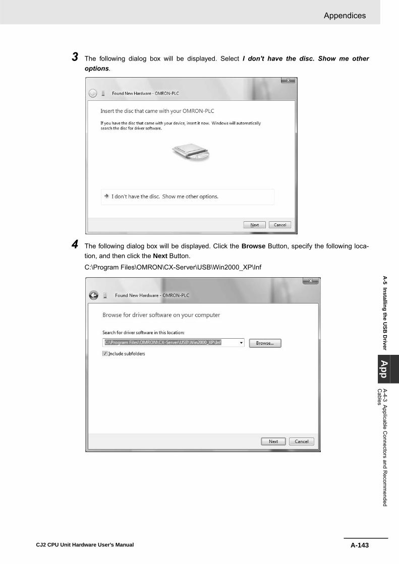
A-143
Appendices
CJ2 CPU Unit Hardware User’s Manual
A-5 Installing the U
SB D
riverA
ppA
-4-3 Applicable C
onnectors and Recom
mended
Cables
3 The following dialog box will be displayed. Select I don't have the disc. Show me otheroptions.
4 The following dialog box will be displayed. Click the Browse Button, specify the following loca-tion, and then click the Next Button.
C:\Program Files\OMRON\CX-Server\USB\Win2000_XP\Inf

Appendices
A-144 CJ2 CPU Unit Hardware User’s Manual
5 Ignore the following dialog box if it is displayed and select Install this driver software anyway.
6 The following dialog box will be displayed when the driver software has been installed success-fully.
� Windows XP
1 The following window will be displayed. Select the Install from a list of specific location Optionand then click the Next Button.
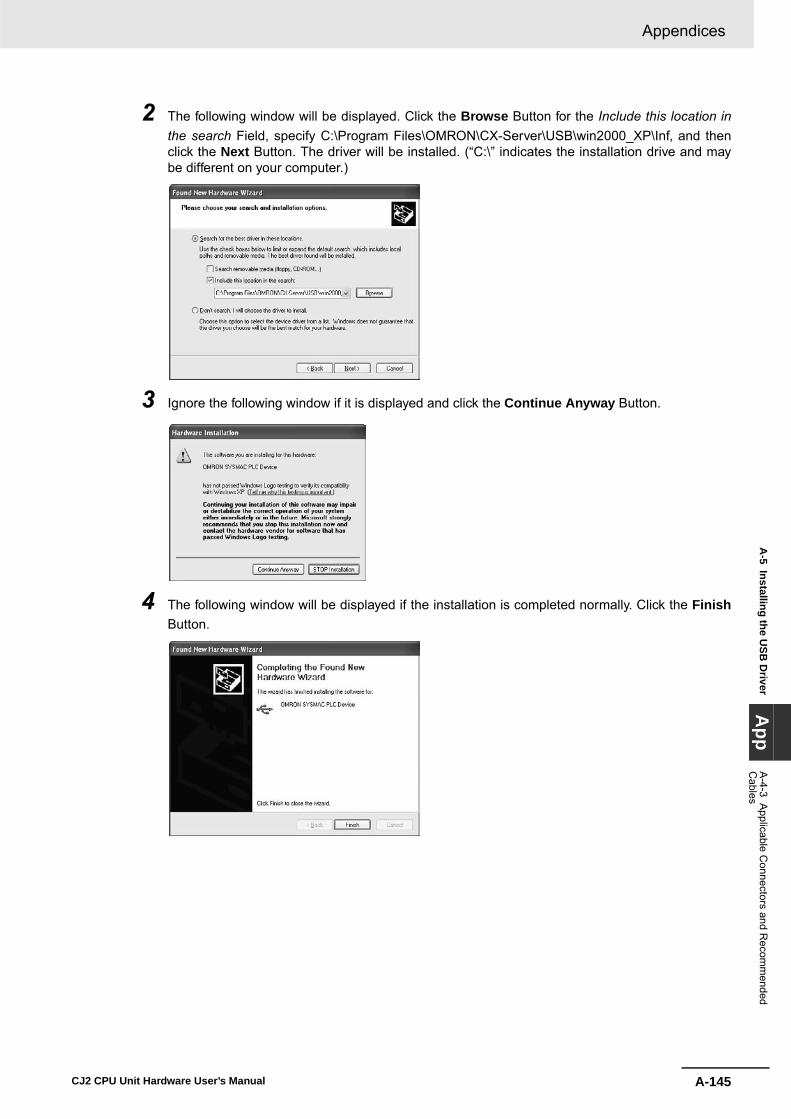
A-145
Appendices
CJ2 CPU Unit Hardware User’s Manual
A-5 Installing the U
SB D
riverA
ppA
-4-3 Applicable C
onnectors and Recom
mended
Cables
2 The following window will be displayed. Click the Browse Button for the Include this location inthe search Field, specify C:\Program Files\OMRON\CX-Server\USB\win2000_XP\Inf, and thenclick the Next Button. The driver will be installed. (“C:\” indicates the installation drive and maybe different on your computer.)
3 Ignore the following window if it is displayed and click the Continue Anyway Button.
4 The following window will be displayed if the installation is completed normally. Click the FinishButton.

Appendices
A-146 CJ2 CPU Unit Hardware User’s Manual
� Windows 2000
1 Turn ON the power supply to the CJ2 PLC, and connect a USB cable between the USB port on
the computer and the peripheral (USB) port on the CJ2 CPU Unit.
After the cable has been connected, the computer will automatically recognize the device andthe following message will be displayed.
2 The following message will be displayed. Click the Next Button.
3 The following window will be displayed.
Select the Search for a suitable driver for the device (recommended) Option and then click theNext Button.

A-147
Appendices
CJ2 CPU Unit Hardware User’s Manual
A-5 Installing the U
SB D
riverA
ppA
-4-3 Applicable C
onnectors and Recom
mended
Cables
4 The following window will be displayed. From the list in the window, select the Specify locationCheck Box and then click the Next Button.
5 Click the Browse Button, specify C:\Program Files\OMRON\CX-Server\USB\win2000_XP\Inf,and then click the Next Button. (“C:\” indicates the installation drive and may be different on yourcomputer.)
6 A search will be made for the driver and the following window will be displayed. Click the NextButton. The driver will be installed.
7 After the driver has been successfully installed, the following window will be displayed. Click theFinish Button.
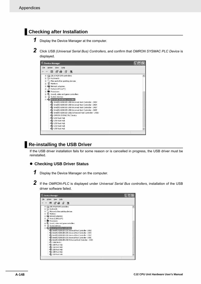
Appendices
A-148 CJ2 CPU Unit Hardware User’s Manual
1 Display the Device Manager at the computer.
2 Click USB (Universal Serial Bus) Controllers, and confirm that OMRON SYSMAC PLC Device isdisplayed.
If the USB driver installation fails for some reason or is cancelled in progress, the USB driver must bereinstalled.
� Checking USB Driver Status
1 Display the Device Manager on the computer.
2 If the OMRON-PLC is displayed under Universal Serial Bus controllers, installation of the USBdriver software failed.
Checking after Installation
Re-installing the USB Driver
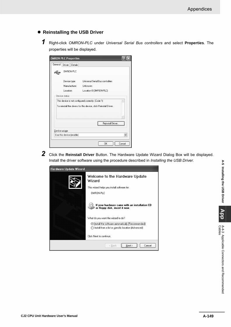
A-149
Appendices
CJ2 CPU Unit Hardware User’s Manual
A-5 Installing the U
SB D
riverA
ppA
-4-3 Applicable C
onnectors and Recom
mended
Cables
� Reinstalling the USB Driver
1 Right-click OMRON-PLC under Universal Serial Bus controllers and select Properties. The
properties will be displayed.
2 Click the Reinstall Driver Button. The Hardware Update Wizard Dialog Box will be displayed.Install the driver software using the procedure described in Installing the USB Driver.

Appendices
A-150 CJ2 CPU Unit Hardware User’s Manual
A-6 Load Short-circuit Protection and Line Disconnection Detection for Basic I/O Units
This section describes the load short-circuit protection of the CJ1W-OD202 Output Units.
As shown below, normally when the output bit turns ON (OUT), the transistor will turn ON and then out-put current (Iout) will flow.
Normal Operation
If the output (Iout) is overloaded or short-circuited exceeding the detection current (Ilim), the output cur-rent (Iout) will be limited as shown in figure below. When the junction temperature (Tj) of the output tran-sistor reaches the thermal shutdown temperature (Tstd), the output will turn OFF to protect thetransistor from being damaged, and the alarm output bit will turn ON to light the ERR indicator. Whenthe junction temperature (Tj) of the transistor drops down to the reset temperature (Tr), the ERR indica-tor will be automatically reset and the output current will start flowing.
Operation for Overload or Short Circuit
If the line is disconnected and the output current (Iout) drops below the line disconnection detection cur-rent (IOL), the ERR indicator will light as shown in the following figure.
Operation for Disconnected Line with Output Current below the Line Disconnection Detection Current
A: Load not connected or load line broken.
B: Current to load at or below line disconnection detection current.
C: Rise of current to load too slow and error detected before the disconnection detection current wasreached.
A-6-1 Load Short-circuit Protection and Line Disconnection Detection for CJ1W-OD202
OUTON
OFF
IOUT
ON
OFF
ERRON
OFF
OUT: OUTPUT instructionIOUT: Output currentERR: Alarm output, ERR indicatorIlim: Short-circuit detection currentIOL: Disconnection detection currentTj: Junction temperature of transistor Tstd: Thermal shutdown temperatureTr: Reset temperature
OUTON
OFF
IOUT
ON
OFF
ERRON
OFF
Ilim
Tj =Tstd Tj =Tr
OUTON
OFF
IOUT
ON
OFF
ERRON
OFF
IOL
A B C

A-151
Appendices
CJ2 CPU Unit Hardware User’s Manual
A-6 Load Short-circuit Protection and Line D
isconnection Detection for B
asic I/O U
nitsA
ppA
-6-1 Load Short-circuit P
rotection and Line D
isconnection Detection for C
J1W-O
D202
When load L is connected, the ERR indicator may light and the Alarm Output Bit may turn ON forapproximately 100 ms. The programming example given later in this section can be used so that anerror is not detected in this case.
� Operating RestrictionsAlthough the CJ1W-OD202 is provided with short-circuit protection, these are for protecting internalcircuits against momentary short-circuiting in the load. As shown in Figure 2, the short-circuit protec-tion is automatically released when the Tj equals to Tr. Therefore, unless the cause of short-circuit isremoved, ON/OFF operations will be repeated in the output. Leaving short-circuits for any length oftime will cause internal temperature rise, deterioration of elements, discoloration of the case orPCBs, etc. Therefore, observe the following restrictions.
� RestrictionsIf a short-circuit occurs in an external load, immediately turn OFF the corresponding output andremove the cause. The CJ1W-OD202 turns ON an alarm output bit that corresponds to the externalload output number. There is an alarm output bit for every common.
When an alarm output bit turns ON, use a self-holding bit for the alarm in the user program and turnOFF the corresponding output.
The alarm output bit is allocated in the Basic I/O Unit Information Area (A050 to A069) for every Unitmounting slot.
The following table shows the correspondence between output bits and bits in the Basic I/O UnitInformation Area.
For example, when the CJ1W-OD202 is mounted in slot 0 on Rack 0, A50.00 will turn ON if the out-put 0 is short-circuited. When the CJ1W-OD202 is mounted in slot 1 of Rack 0, A50.11 will turn ONif the output 7 is short-circuited.
� Programming ExampleIn this example, CJ1W-OD202 is mounted in slot 0 of the Rack 0.
This example shows how to turn OFF output bits CIO 0.00 immediately if the alarm output bit A50.00turns ON and how to keep the output bits OFF until the cause is removed and the bit is reset usingwork bit W0.01.
Change to CIO 0.00, CIO 1.00, 0 (under TIM and at bottom right of diagram), A50.00, and W0.01.
To prevent the alarm output bit from turning ON momentarily when the load turns ON, the alarm out-put is not turned ON for 200 ms after the input (CIO 1.00) turns ON.
Output bit 0 to 1 2 to 3 4 to 5 6 to 7CJ1W-OD202 Mounted in even slot 0 1 2 3
Mounted in odd slot 8 9 10 11
TIM0W0.00
W0.01
A50.00 1.00 TIM 0000
#0002
W0.00
1.00
0.00
W0.00
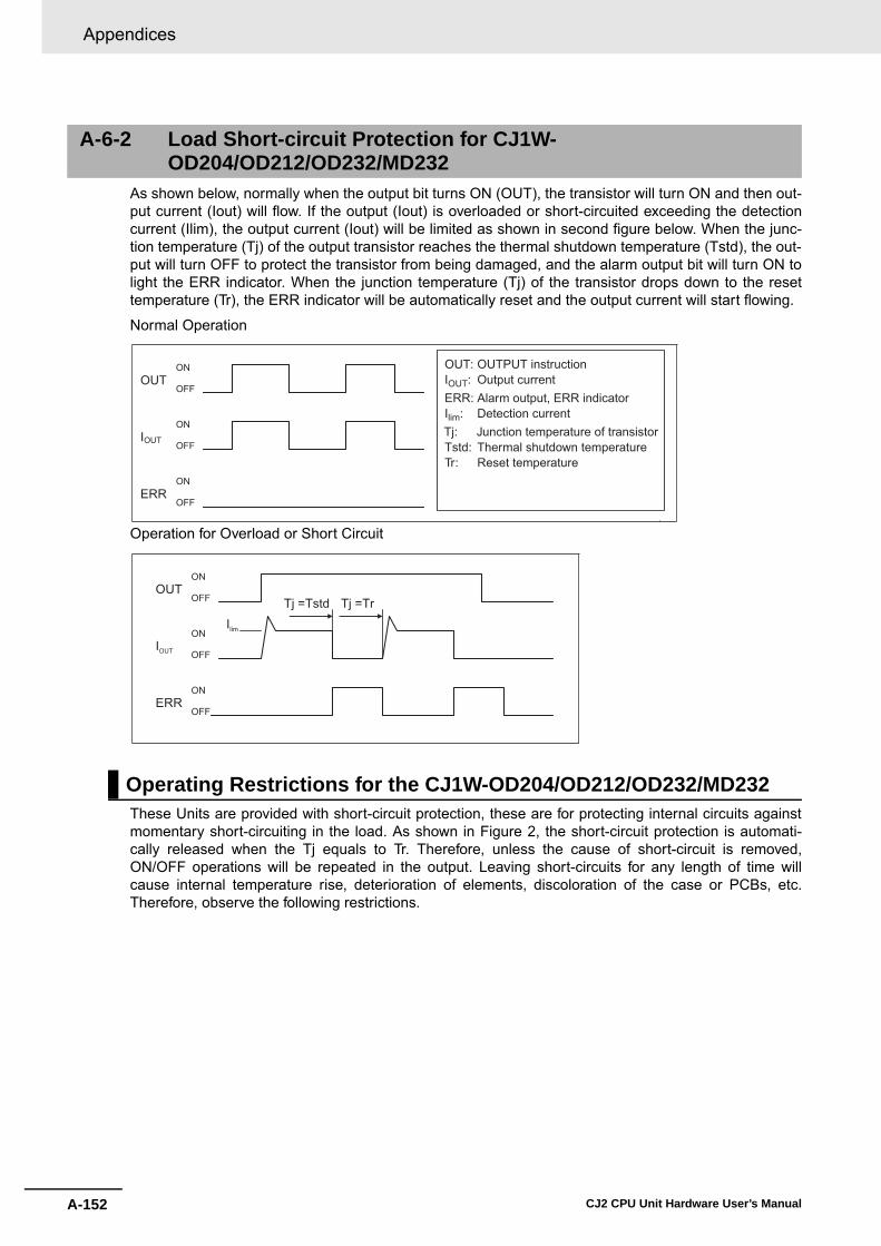
Appendices
A-152 CJ2 CPU Unit Hardware User’s Manual
As shown below, normally when the output bit turns ON (OUT), the transistor will turn ON and then out-put current (Iout) will flow. If the output (Iout) is overloaded or short-circuited exceeding the detectioncurrent (Ilim), the output current (Iout) will be limited as shown in second figure below. When the junc-tion temperature (Tj) of the output transistor reaches the thermal shutdown temperature (Tstd), the out-put will turn OFF to protect the transistor from being damaged, and the alarm output bit will turn ON tolight the ERR indicator. When the junction temperature (Tj) of the transistor drops down to the resettemperature (Tr), the ERR indicator will be automatically reset and the output current will start flowing.
Normal Operation
Operation for Overload or Short Circuit
These Units are provided with short-circuit protection, these are for protecting internal circuits againstmomentary short-circuiting in the load. As shown in Figure 2, the short-circuit protection is automati-cally released when the Tj equals to Tr. Therefore, unless the cause of short-circuit is removed,ON/OFF operations will be repeated in the output. Leaving short-circuits for any length of time willcause internal temperature rise, deterioration of elements, discoloration of the case or PCBs, etc.Therefore, observe the following restrictions.
A-6-2 Load Short-circuit Protection for CJ1W-OD204/OD212/OD232/MD232
Operating Restrictions for the CJ1W-OD204/OD212/OD232/MD232
OUTON
OFF
IOUT
ON
OFF
ERRON
OFF
OUT: OUTPUT instructionIOUT: Output currentERR: Alarm output, ERR indicatorIlim: Detection currentTj: Junction temperature of transistorTstd: Thermal shutdown temperatureTr: Reset temperature
OUTON
OFF
IOUT
ON
OFF
ERR ON
OFF
Ilim
Tj =Tstd Tj =Tr
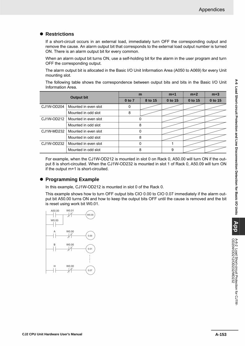
A-153
Appendices
CJ2 CPU Unit Hardware User’s Manual
A-6 Load Short-circuit Protection and Line D
isconnection Detection for B
asic I/O U
nitsA
ppA
-6-2 Load Short-circuit P
rotection for CJ1W
-O
D204/O
D212/O
D232/M
D232
� RestrictionsIf a short-circuit occurs in an external load, immediately turn OFF the corresponding output andremove the cause. An alarm output bit that corresponds to the external load output number is turnedON. There is an alarm output bit for every common.
When an alarm output bit turns ON, use a self-holding bit for the alarm in the user program and turnOFF the corresponding output.
The alarm output bit is allocated in the Basic I/O Unit Information Area (A050 to A069) for every Unitmounting slot.
The following table shows the correspondence between output bits and bits in the Basic I/O UnitInformation Area.
For example, when the CJ1W-OD212 is mounted in slot 0 on Rack 0, A50.00 will turn ON if the out-put 8 is short-circuited. When the CJ1W-OD232 is mounted in slot 1 of Rack 0, A50.09 will turn ONif the output m+1 is short-circuited.
� Programming ExampleIn this example, CJ1W-OD212 is mounted in slot 0 of the Rack 0.
This example shows how to turn OFF output bits CIO 0.00 to CIO 0.07 immediately if the alarm out-put bit A50.00 turns ON and how to keep the output bits OFF until the cause is removed and the bitis reset using work bit W0.01.
Output bitm m+1 m+2 m+3
0 to 7 8 to 15 0 to 15 0 to 15 0 to 15CJ1W-OD204 Mounted in even slot 0
Mounted in odd slot 8
CJ1W-OD212 Mounted in even slot 0
Mounted in odd slot 8
CJ1W-MD232 Mounted in even slot 0
Mounted in odd slot 8
CJ1W-OD232 Mounted in even slot 0 1
Mounted in odd slot 8 9
A0.00
W0.00
B0.01
W0.00
H0.07
W0.00
A50.00W0.00
W0.01
W0.00
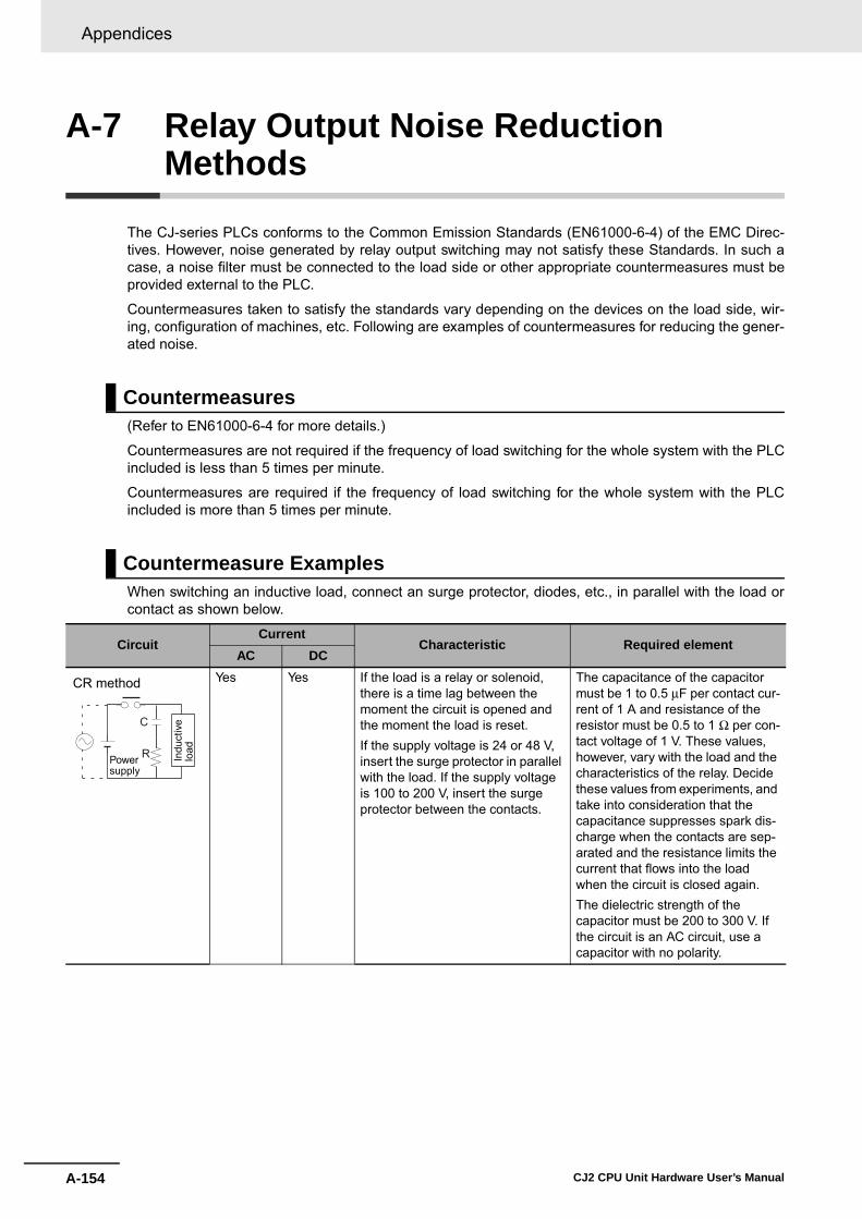
Appendices
A-154 CJ2 CPU Unit Hardware User’s Manual
A-7 Relay Output Noise Reduction Methods
The CJ-series PLCs conforms to the Common Emission Standards (EN61000-6-4) of the EMC Direc-tives. However, noise generated by relay output switching may not satisfy these Standards. In such acase, a noise filter must be connected to the load side or other appropriate countermeasures must beprovided external to the PLC.
Countermeasures taken to satisfy the standards vary depending on the devices on the load side, wir-ing, configuration of machines, etc. Following are examples of countermeasures for reducing the gener-ated noise.
(Refer to EN61000-6-4 for more details.)
Countermeasures are not required if the frequency of load switching for the whole system with the PLCincluded is less than 5 times per minute.
Countermeasures are required if the frequency of load switching for the whole system with the PLCincluded is more than 5 times per minute.
When switching an inductive load, connect an surge protector, diodes, etc., in parallel with the load orcontact as shown below.
Countermeasures
Countermeasure Examples
CircuitCurrent
Characteristic Required elementAC DC
Yes Yes If the load is a relay or solenoid, there is a time lag between the moment the circuit is opened and the moment the load is reset.If the supply voltage is 24 or 48 V, insert the surge protector in parallel with the load. If the supply voltage is 100 to 200 V, insert the surge protector between the contacts.
The capacitance of the capacitor must be 1 to 0.5 μF per contact cur-rent of 1 A and resistance of the resistor must be 0.5 to 1 Ω per con-tact voltage of 1 V. These values, however, vary with the load and the characteristics of the relay. Decide these values from experiments, and take into consideration that the capacitance suppresses spark dis-charge when the contacts are sep-arated and the resistance limits the current that flows into the load when the circuit is closed again.The dielectric strength of the capacitor must be 200 to 300 V. If the circuit is an AC circuit, use a capacitor with no polarity.
CR method
Power supply
Indu
ctiv
elo
ad
C
R

A-155
Appendices
CJ2 CPU Unit Hardware User’s Manual
A-7 R
elay Output N
oise Reduction M
ethodsA
ppA
-6-2 Load Short-circuit P
rotection for CJ1W
-O
D204/O
D212/O
D232/M
D232
When switching a load with a high inrush current such as an incandescent lamp, suppress the inrushcurrent as shown below.
No Yes The diode connected in parallel with the load changes energy accu-mulated by the coil into a current, which then flows into the coil so that the current will be converted into Joule heat by the resistance of the inductive load.This time lag, between the moment the circuit is opened and the moment the load is reset, caused by this method is longer than that caused by the CR method.
The reversed dielectric strength value of the diode must be at least 10 times as large as the circuit volt-age value. The forward current of the diode must be the same as or larger than the load current.The reversed dielectric strength value of the diode may be two to three times larger than the supply voltage if the surge protector is applied to electronic circuits with low circuit voltages.
Yes Yes The varistor method prevents the imposition of high voltage between the contacts by using the constant voltage characteristic of the varis-tor. There is time lag between the moment the circuit is opened and the moment the load is reset.If the supply voltage is 24 or 48 V, insert the varistor in parallel with the load. If the supply voltage is 100 to 200 V, insert the varistor between the contacts.
---
CircuitCurrent
Characteristic Required elementAC DC
Diode method
Powersupply
Indu
ctiv
elo
ad
Powersupply
Varistor method
Indu
ctiv
elo
ad
OUT
COM
ROUT
COM
R
Countermeasure 1 Countermeasure 2
Providing a dark current ofapprox. one-third of the ratedvalue through an incandescentlamp
Providing a limiting resistor

Appendices
A-156 CJ2 CPU Unit Hardware User’s Manual
A-8 Functions Supported for Unit Versions
CX-Programmer version 9.1 or higher must be used to enable using the functions added for unit ver-sion 1.3.
CX-Programmer version 8.3 or higher must be used to enable using the functions added for unit ver-sion 1.2.
Note User programs that use functions of CJ2H CPU Units with unit version 1.2 or later cannot be used with CJ2HCPU Units with unit version 1.1 or earlier. If an attempt is made to transfer a program that uses any of thesefunctions from the CX-Programmer to a CPU Unit with unit version 1.1 or earlier, an error will be displayedand it will not be possible to download to the CPU Unit.
CX-Programmer version 8.1* or higher must be used to enable using the functions added for unit ver-sion 1.1.
Functions Supported for Unit Version 1.3 or Later
Units CJ2H CPU Units
Models CJ2H-CPU6@-EIP and CJ2H-CPU6@
Unit versionFunction
Unit version 1.3 or later
Unit version 1.2
Unit version 1.1
Unit version 1.0
Special instructions for certain Special I/O Units
CJ1W-NC281/NC481/NC881 Position Control Units: PCU HIGH-SPEED POSITIONING (NCDMV(218))
Supported. Not supported. Not supported. Not supported.
CJ1W-NC281/NC481/NC881 Position Control Units: PCU POSITIONING TRIGGER (NCDTR(219))
Supported. Not supported. Not supported. Not supported.
New special instruc-tions
SIGNED AREA RANGE COM-PARE: ZCPS(088)
Supported. Not supported. Not supported. Not supported.
DOUBLE SIGNED AREA RANGE COMPARE: ZCPSL(116)
Supported. Not supported. Not supported. Not supported.
Unit Version 1.2 or Later
Unit CJ2H CPU Units
ModelCJ2H-CPU6@-EIP
CJ2H-CPU6@
Unit version Unit version 1.2 or later Other unit versions
EM Area Force-setting/resetting Supported. Not supported.
Functions Supported for Unit Version 1.1 or Later
Units CJ2H CPU Unit
Models CJ2H-CPU6@-EIP andCJ2H-CPU6@
Unit versionFunction Unit version 1.1 Unit version 1.0
High-speed interrupt functionReduced overhead time for interrupt tasksMinimum interval for scheduled interrupt task execution: 0.1 ms
Supported. Not supported.
Changing the minimum cycle time setting during operation Supported. Not supported.

A-157
Appendices
CJ2 CPU Unit Hardware User’s Manual
A-8 Functions Supported for U
nit VersionsA
ppA
-6-2 Load Short-circuit P
rotection for CJ1W
-O
D204/O
D212/O
D232/M
D232
* CX-Programmer version 8.02 or higher is required to use the high-speed interrupt function and the function tochange the minimum cycle time setting during operation.
Note User programs that use functions of CJ2H CPU Units with unit version 1.1 or later cannot be used with CJ2HCPU Units with unit version 1.0 or earlier. If an attempt is made to transfer a program that uses any of thesefunctions from the CX-Programmer to a CPU Unit with unit version 1.0, an error will be displayed and it willnot be possible to download to the CPU Unit. If a program file (extension: .OBJ) that uses any of these func-tions is transferred to a CPU Unit with unit version 1.0, a program error will occur when operation starts orwhen the function starts and operation of the CPU Unit will stop.
Synchronous unit operation Supported. Not supported.
Addition of immediate refreshing instructions for certain Special I/O UnitsCJ1W-AD042 High-speed Analog Input Unit: ANALOG INPUT DIRECT CONVERSION (AIDC(216))CJ1W-DA042V High-speed Analog Output Unit: ANALOG OUTPUT DIRECT CONVERSION (AODC(217))
Supported. Not supported.
High-speed Serial Communications UnitsCJ1W-SCU22/SCU32/SCU42 High-speed Serial Communications Units: DIRECT RECEIVE VIA SERIAL COMMUNICATIONS UNIT (DRXDU(261)) and DIRECT TRANSMIT VIA SERIAL COMMUNICATIONS UNIT (DTXDU(262))
Supported. Not supported.
Units CJ2H CPU Unit
Models CJ2H-CPU6@-EIP andCJ2H-CPU6@
Unit versionFunction Unit version 1.1 Unit version 1.0

Appendices
A-158 CJ2 CPU Unit Hardware User’s Manual

Index-1CJ2 CPU Unit Hardware User’s Manual
Index
A
alarm output ................................................................ 3-23
B
Basic I/O Units ............................................................ 2-14Basic I/O Units specifications ........................................ A-2battery replacement procedure ..................................... 7-6battery service life and replacement periods ................ 7-5
C
calculating power consumption ................................... 2-24calculating unit current consumption ........................... 2-21checking errors ............................................................. 6-2Connector-Terminal Block Conversion Unit .......5-33, A-59CPU Bus Units ............................................................ 2-20CPU error .................................................................... 6-10CPU error (WDT error) .................................................. 6-6CPU Rack ..................................................................... 2-3CPU reset ..................................................................... 6-9CPU reset error ............................................................. 6-6CPU standby error ................................................. 6-6, 6-8current consumption .....................2-5, 2-6, 2-7, 2-11, 2-14
D
dimensions ...........................................................5-8, A-94DIN Track ............................................................. 2-9, 5-15DIP switch .............................................................. 3-3, 3-6
E
End Cover ..................................................................... 2-3error log information ...................................................... 6-3EtherNet/IP port ..................................................... 2-9, 4-9Expansion Rack .......................................................... 2-10
F
fail-safe circuit ............................................................... 5-2fatal errors ..........................................................6-6, A-103
cycle time exceeded error ...................6-6, 6-12, A-104FALS(007) error ............................................6-6, A-107I./O setting error .................................................. A-105I/O bus error ........................................6-6, 6-13, A-104I/O setting error .............................................. 6-6, 6-15Memory Card transfer error ..........................6-6, A-107memory error .......................................6-6, 6-16, A-107program error ...............................................6-6, A-106too many I/O points ................................................. 6-6too many I/O points error ..................................... A-105Unit/Rack number duplication error ..................... A-105version error .................................................6-6, A-107
G
grounding .................................................................... 5-49
I
I/O Relay Terminal ...................................................... 5-33I/O Relay Terminals connection patterns ....................A-60I/O table verification ...................................................... 6-5indicators ................................................................ 3-4, 6-2Interrupt Input Unit ...................................................... 3-25IP address ................................................................... 3-12
L
line disconnection detection ...................................... A-150
M
Memory Card ....................................................... 3-3, 3-13Memory Card connector ............................................... 3-3Memory Card indicator .................................................. 3-5Memory Card indicators ................................................ 3-3Memory Card power supply switch ............................... 3-3
N
node address .............................................................. 3-12non-fatal errors ...................................................6-6, A-108
backup memory error ...................................6-6, A-109Basic I/O error ..............................................6-6, A-109basic I/O error ........................................................ 6-18battery error .........................................6-6, 6-20, A-109CPU Bus Unit error ..............................6-6, 6-21, A-109CPU Bus Unit setting error ...........................6-6, A-109duplicated refreshing error ...........................6-6, A-109FAL(006) error ..............................................6-6, A-110PLC Setup error ...........................................6-6, A-109Special I/O Unit error ...........................6-6, 6-22, A-109Special I/O Unit setting error ........................6-6, A-110tag memory error ..........................................6-6, A-109
O
Option Board error ............................................... 6-6, 6-19
P
periodic inspection ........................................................ 7-2peripheral (USB) port .................................... 3-3, 4-5, 6-11PLC Backup Tool ........................................................... 8-2Power supply error ........................................................ 6-6power supply error ........................................................ 6-7Power Supply Unit replacement time .......................... 7-10Power Supply Units ..................................................... 3-18program capacity ................................................... 2-5, 2-6
Index-2 CJ2 CPU Unit Hardware User’s Manual
R
replacement notification .............................................. 7-10rotary switch ................................................................ 3-11RS-232C ...................................................................... 6-11RS-232C interface .....................................................A-111RS-232C Option Board
specifications .......................................................A-112RS-232C port communications error ............................. 6-6RS-422A/485 Option Board
specifications .......................................................A-113RUN output .................................................................. 3-23
S
Serial Option Board ......................................... 3-17, A-101serial port ...............................................................2-9, 3-3serial port (RS-232C) .................................................... 4-8seven-segment display .........................................3-9, 6-26short-circuit protection ...............................................A-150simple backup ............................................................... 8-7Special I/O Units .......................................................... 2-17Support Software .......................................................... 4-2
U
unit address ................................................................. 8-14USB driver .................................................................A-140USB port .................................................................2-9, 4-5USB port communications error .................................... 6-6
W
weight .................................................... 2-5, 2-6, 2-7, 2-14wiring duct ..................................................................... 5-7
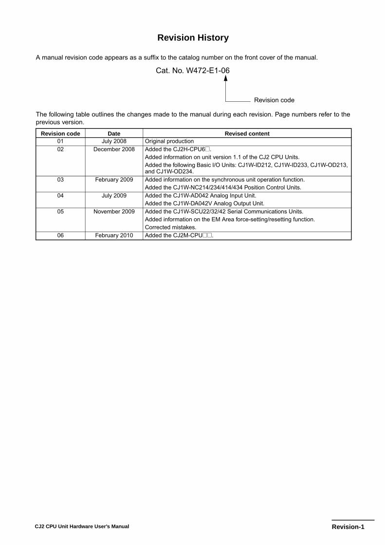
Revision-1CJ2 CPU Unit Hardware User’s Manual
Revision History
A manual revision code appears as a suffix to the catalog number on the front cover of the manual.
The following table outlines the changes made to the manual during each revision. Page numbers refer to theprevious version.
Revision code Date Revised content01 July 2008 Original production02 December 2008 Added the CJ2H-CPU6@.
Added information on unit version 1.1 of the CJ2 CPU Units.Added the following Basic I/O Units: CJ1W-ID212, CJ1W-ID233, CJ1W-OD213, and CJ1W-OD234.
03 February 2009 Added information on the synchronous unit operation function. Added the CJ1W-NC214/234/414/434 Position Control Units.
04 July 2009 Added the CJ1W-AD042 Analog Input Unit.Added the CJ1W-DA042V Analog Output Unit.
05 November 2009 Added the CJ1W-SCU22/32/42 Serial Communications Units. Added information on the EM Area force-setting/resetting function.Corrected mistakes.
06 February 2010 Added the CJ2M-CPU@@.
Cat. No. W472-E1-06
Revision code

Revision-2 CJ2 CPU Unit Hardware User’s Manual


Authorized Distributor:
In the interest of product improvement, specifications are subject to change without notice.
Cat. No. W472-E1-06Printed in Japan
0210
© OMRON Corporation 2008 All Rights Reserved.
OMRON Corporation Industrial Automation Company
OMRON ELECTRONICS LLCOne Commerce Drive Schaumburg,IL 60173-5302 U.S.A.Tel: (1) 847-843-7900/Fax: (1) 847-843-7787
Regional HeadquartersOMRON EUROPE B.V.Wegalaan 67-69-2132 JD HoofddorpThe NetherlandsTel: (31)2356-81-300/Fax: (31)2356-81-388
Contact: www.ia.omron.comTokyo, JAPAN
OMRON ASIA PACIFIC PTE. LTD.No. 438A Alexandra Road # 05-05/08 (Lobby 2), Alexandra Technopark, Singapore 119967Tel: (65) 6835-3011/Fax: (65) 6835-2711
OMRON (CHINA) CO., LTD.Room 2211, Bank of China Tower, 200 Yin Cheng Zhong Road, PuDong New Area, Shanghai, 200120, ChinaTel: (86) 21-5037-2222/Fax: (86) 21-5037-2200