city of victoria drainage criteria manual
TRANSCRIPT

448153 i
City of Victoria
Drainage Criteria Manual
Prepared for:
City of Victoria
Public Works Department
Prepared by:
PBS&J
6504 Bridge Point Parkway, Suite 200
Austin, Texas 78730
May 2007

448153 ii
Table of Contents
1.0 INTRODUCTION.......................................................................................................................................... 1-1
2.0 DRAINAGE POLICIES................................................................................................................................ 2-1
2.1 GENERAL DRAINAGE POLICIES........................................................................................2-1 2.1.1 Definitions.................................................................................................................2-1 2.1.2 Drainage Impacts .....................................................................................................2-4
2.2 CONSTRAINTS AND REQUIREMENTS..............................................................................2-4 2.2.1 Jurisdiction ...............................................................................................................2-4 2.2.2 Base Impervious Cover Limits .................................................................................2-4 2.2.3 Drainage Study.........................................................................................................2-5 2.2.4 Interim Phasing ........................................................................................................2-6 2.2.5 Incremental Development ........................................................................................2-6 2.2.6 Small Development (areas less than 5 acres) .........................................................2-6 2.2.7 Drainage Easements................................................................................................2-6 2.2.8 Storm water Detention .............................................................................................2-7
2.3 DRAINAGE DESIGN POLICIES ...........................................................................................2-7 2.3.1 Design Frequencies .................................................................................................2-7 2.3.2 Design Conditions ....................................................................................................2-8 2.3.3 Street Drainage ........................................................................................................2-8 2.3.4 Inlets.........................................................................................................................2-8 2.3.5 Storm Drains and Open Channels ...........................................................................2-9 2.3.6 Bridges and Culverts ..............................................................................................2-10 2.3.7 Erosion and Sedimentation Control .......................................................................2-10 2.3.8 Design Calculations and Required Technical Backup ...........................................2-10 2.3.9 Lot Grading Requirements .....................................................................................2-13 2.3.10 Preparation of Construction Drawings and Specifications for
Improvements to be Dedicated to the Public .........................................................2-14
SECTION 2.0 FIGURES AND TABLES INDEX ............................................................................2-17
3.0 DETERMINATION OF STORM RUNOFF FROM SMALL AREAS........................................................ 3-1
3.1 RAINFALL .............................................................................................................................3-1
3.2 RATIONAL METHOD............................................................................................................3-1 3.2.1 Runoff Coefficient.....................................................................................................3-1 3.2.2 Time of Concentration..............................................................................................3-1 3.2.3 Rainfall Intensity .......................................................................................................3-2
3.3 SECTION 3.0 FIGURES AND TABLES INDEX....................................................................3-3
4.0 DETERMINATION OF STORM RUNOFF FROM LARGE AREAS........................................................ 4-1
4.1 RAINFALL DATA...................................................................................................................4-1 4.1.1 Rainfall Duration and Total Rainfall..........................................................................4-1 4.1.2 Rainfall Distribution ..................................................................................................4-1
4.2 UNIT HYDROGRAPH ...........................................................................................................4-1 4.2.1 Unit Hydrograph Parameters ...................................................................................4-1
4.3 LOSS RATE ..........................................................................................................................4-2

448153 iii
4.3.1 Flow Routing ............................................................................................................4-3
4.4 SECTION 4.0 FIGURES AND TABLES INDEX....................................................................4-4
5.0 DRAINAGE DESIGN ................................................................................................................................... 5-1
5.1 DESIGN REQUIREMENTS ..................................................................................................5-1
5.2 DESIGN OF STORM DRAINS..............................................................................................5-1 5.2.1 Design Goals............................................................................................................5-1 5.2.2 Design Frequency ....................................................................................................5-2 5.2.3 Velocity Considerations............................................................................................5-3 5.2.4 Inlets.........................................................................................................................5-3 5.2.5 Manholes and Junction Boxes .................................................................................5-5 5.2.6 Storm Drain Sizes and Placement ...........................................................................5-5 5.2.7 Storm Drain Design Methodology ............................................................................5-6 5.2.8 Starting Water Surface and Hydraulic Gradient.......................................................5-7
5.3 CONSIDERATION OF “OVERLAND RELIEF “FLOW..........................................................5-7 5.3.1 Design Frequency ....................................................................................................5-7 5.3.2 Relationship of Structures to Street .........................................................................5-7 5.3.3 Calculation of Flow...................................................................................................5-8
5.4 DESIGN OF OPEN CHANNELS...........................................................................................5-8 5.4.1 Design Frequency ....................................................................................................5-8 5.4.2 Determination of Water Surface Elevation...............................................................5-8 5.4.3 Design of Culverts ....................................................................................................5-9
5.5 DESIGN OF ROADSIDE DITCHES......................................................................................5-9 5.5.1 Design Frequency ....................................................................................................5-9 5.5.2 Velocity Considerations............................................................................................5-9 5.5.3 Culverts ..................................................................................................................5-10 5.5.4 Invert Protection .....................................................................................................5-10 5.5.5 Depth and Size Limitations ....................................................................................5-10
5.6 DESIGN OF OUTFALLS.....................................................................................................5-10
5.7 SECTION 5.0 FIGURES AND TABLES INDEX..................................................................5-11
6.0 STORM WATER DETENTION ................................................................................................................... 6-1
6.1 APPLICATION OF DETENTION...........................................................................................6-1
6.2 CALCULATION OF DETENTION VOLUME.........................................................................6-1
6.3 CALCULATION OF OUTLET SIZE.......................................................................................6-1
6.4 OWNERSHIP AND EASEMENTS ........................................................................................6-2
7.0 STORM DRAINAGE MASTER PLAN ....................................................................................................... 7-1
8.0 GLOSSARY.................................................................................................................................................. 8-1
9.0 BIBLIOGRAPHY.......................................................................................................................................... 9-1

448153 1-1
1.0 INTRODUCTION
The purpose of this Storm Drainage Design Criteria Manual (DCM) is to establish the storm drainage
design criteria and storm drainage design procedures for development and capital improvements within
the City of Victoria, Texas, and it’s Extraterritorial Jurisdiction (ETJ). These criteria and procedures were
used in the preparation of the Storm Drainage Master Plan (SDMP) the results of which are presented in
another document.
The overall “style” of this DCM is in the form of a “users guide” with the overall drainage policies
presented in Section 2 and the methods and applicable nomographs and tables presented in subsequent
sections and associated appendices. The DCM is not intended to be a lengthy educational textbook with
pages of theory and equations. It is assumed that the user of this DCM will already have a working
knowledge of the basic mathematical theories involved in hydrology and hydraulics and is simply looking
for the “standard practices” of the City. A Bibliography will be presented at the end of the DCM should
the user wish to make further study of the theories within a particular hydrologic or hydraulic area.
Each design section includes a list of “deliverables” that should be submitted to the City as “backup” for
an individual design review submittal package. These lists will focus on “what” is to be submitted, the
“how” is left to the discretion of the developer/designer within the boundaries presented in the DCM.

441184/030203 2-1
2.0 DRAINAGE POLICIES
These policies shall govern the planning, design and construction of storm drainage facilities within the
City of Victoria, Texas and within all areas subject to its extraterritorial jurisdiction.
2.1 GENERAL DRAINAGE POLICIES
A Storm Drainage Master Plan (SDMP) has been developed and implemented by the City of Victoria.
The SDMP establishes the baseline drainage conditions to be used in the regulation of development
within the City and its Extra Territorial Jurisdiction (ETJ), provides a set of hydrologic and hydraulic
models for the major watersheds, outlines plans to eliminate or significantly reduce flooding along the
City’s drainage systems and describes the assumptions and methodologies used to develop this
information. As part of the overall work associated with the SDMP, the City’s Drainage Criteria Manual
(DCM) was updated to provide consistent and standard policy and methods to design and evaluate
drainage systems within the City and its ETJ.
In order to manage future development and to guide use of the SDMP and DCM within the City and its
ETJ, revisions to the City’s drainage policies are also required. These policies are being proposed such
that new development can occur within the City and its ETJ with thorough considerations for flood
potential to property and existing homes.
2.1.1 Definitions
1. Development - Any man-made change to improved or unimproved real estate, including, but not
limited to, buildings or other structures, mining, dredging, filling, grading, paving, excavation or
drilling operations located within the City and its ETJ.
2. Drainage Conditions – There are several drainage conditions that shall be considered or evaluated in
the preparation of a development application. Each drainage condition represents a different
combination of level of development within a watershed and condition of the major drainage system
serving that watershed.
a. Baseline Drainage Condition (Baseline) – The baseline drainage condition for areas within the
Victoria City limits and ETJ shall be the Present/Present drainage condition as defined in the
SDMP. The SDMP provides a baseline set of existing condition hydrologic and hydraulic models
for the major drainage systems within the Victoria city limits and ETJ. The Present/Present
drainage condition established by the SDMP denotes first, the “present” level of development
within a watershed and second, the “present” condition of the main or primary drainage system at
the time of the SDMP. These models were developed based on 1997 development and main
channel conditions. However, the baseline condition will be used for the determination of any
impacts that necessitate the implementation of interim or permanent flood control measures.

448153 2-2
b. Future Drainage Conditions (Future/Future) – The future drainage condition denotes the future
(i.e. ultimate) level of development anticipated within a watershed along with future (i.e.
ultimate) drainage system modifications called for in the SDMP. The SDMP provides a set of
future/future condition hydrologic and hydraulic models that reflect full watershed development
conditions (as described under the Impervious Cover section below) and SDMP main channel
improvements anticipated for each major watershed within the City and ETJ. The watershed-
specific flows and water surface elevations from these future condition SDMP models were
achieved as a result of the flood control measures selected in the SDMP. Further, these flood
control measures will achieve the goal of preventing increases in flooding potential above
baseline conditions as the respective watersheds develop. All new or proposed developments
should evaluate and consider both the baseline and future drainage conditions.
c. Drainage Conditions Associated with Drainage Studies for Development – In order to properly
evaluate the potential for flood impacts associated with a development site, it may be necessary to
update the hydrologic and/or hydraulic modeling conditions to reflect the state of the system and
the development within a watershed at the time of the development application The following
conditions describe possible watershed development and main channel/creek conditions that
could exist when a development application is submitted to the City.
i. Present/Present Condition (Present/Present) – The present/present drainage condition denotes
watershed conditions, specifically including the degree of current watershed development as
well as the major drainage system conditions at the time of the development application.
This condition would include any modifications made to the major drainage system since the
establishment of the baseline condition.
ii. Future/Existing Drainage Conditions (Future/Present) – The future/present drainage condition
denotes watershed conditions, specifically including the proposed development (impervious
cover, land use, etc.) and the current (at the time of the development application) major
drainage system condition.
iii. Future/Future Drainage Condition (Future/Future) – The future/future drainage condition
denotes the watershed conditions, specifically including the proposed development as well as
any modifications associated with the major drainage system.
3. Impervious Cover –Roads, parking lots, sidewalks, rooftops and other impermeable surfaces that tend
to decrease the infiltration of rainfall into the ground, increase runoff volumes, increase runoff peak
flows, increase runoff flow velocities, and decrease runoff times.
4. Infill Development – Development of small, undeveloped properties within larger, predominantly
urbanized areas.

448153 2-3
5. Interim Phasing – The process to be followed between the time of approval of a development and the
time at which the drainage system is upgraded to the level proposed for future conditions in the
SDMP. In cases where the drainage system has not been improved at the time of development, the
developer will be required to mitigate any increases in flow or water level above the baseline
condition levels in the watershed.
6. Major Drainage System – A major drainage system within the City of Victoria and ETJ is a system
that was studied in detail in the SDMP. These systems include both open channels and closed
systems. Refer to the SDMP for a full description of the major drainage systems.
a. The major open channel systems within City and ETJ are:
� Jim Branch Outfall
� South Outfall
� West Outfall
� Spring Creek
� Whispering Creek
� North Outfall/US 77 Outfall
� Lone Tree Creek (including the East Branch of Lone Tree Creek and the Southern Pacific
Railroad Ditch)
� Marcado Creek
b. The major closed systems include large tributary systems to the major open channel systems
listed above and the following named systems.
� Second Street Outfall
� Mockingbird Outfall
7. Redevelopment – Removal of the existing development on a property and construction of new
development on that same property.
8. Regulatory Flood Elevations – Refer to the City of Victoria Flood Damage Prevention Ordinance for
additional definitions and requirements.

448153 2-4
a. FEMA Effective Base Flood – Elevations associated with this flood condition are defined as
flood elevations that have a 1% chance of occurring in any given year. This 1% annual chance
event defines the floodplains and flood elevations that are used in the determination of the need
for, and cost of, flood insurance for a property. It is anticipated that FEMA will update base
flood elevations to be consistent with, and/or primarily based on, the SDMP hydrologic and
hydraulic modeling that has been performed.
b. Baseline Condition Flood – Elevations associated with this flood event are the primary regulatory
elevations to be used in consideration of all development within the City of Victoria and its ETJ
and is based on the 1% annual chance event with the assumptions of watershed development and
major drainage system conditions set at 1997 levels as outlined in the SDMP. The baseline
condition base flood has been established with the present/present condition hydrologic and
hydraulic models from the SDMP.
2.1.2 Drainage Impacts
2.1.2.1 Baseline Condition Drainage System
Runoff-related impacts associated with a development may not increase the flood conditions above the
baseline established by the SDMP. Any increase over the baseline must be mitigated through onsite
detention, additional conveyance increases or additional purchase of drainage easements at the expense of
the developer.
2.1.2.2 Structures (Bridges and Culverts)
The impacts of a development may not result in any increase in the base flood elevation at any structures
(downstream or upstream) that would exceed the overtopping depths allowed by the DCM. Any such
impacts will require temporary mitigation by the developer.
2.2 CONSTRAINTS AND REQUIREMENTS
2.2.1 Jurisdiction
The drainage policies, DCM, and floodplain ordinances for the City of Victoria shall apply to areas within
both the city limits and the ETJ of the City of Victoria.
2.2.2 Base Impervious Cover Limits
1. The SDMP established the allowable levels of impervious cover under future conditions as 43%
(forty three percent) in residential areas and 85% (eighty five percent) impervious cover for
commercial and other land use developments in strips along selected highways and major arterial
streets. The more intensely developed strips extend a distance of 200 (two hundred) feet from the

448153 2-5
center line on each side of the road. Refer to the SDMP for the roads with such commercial/densely
developed strips.
2. Any development that exceeds the SDMP impervious cover limitations must provide permanent
onsite detention sufficient to mitigate for the additional impervious cover and to ensure that the future
condition peak flow discharging from the proposed development does not exceed the peak flow from
the development area under SDMP conditions. Temporary detention must be provided and
maintained by the developer until downstream SDMP improvements are constructed. If a
development limits its impervious cover within each major watershed to the SDMP limits, no
permanent storm water detention will be required.
2.2.3 Drainage Study
1. A drainage study using the City’s DCM performed and/or supervised by a licensed professional
engineer is required for all development other than single family residential development that does
not involve the subdivision of land. The study must consider watershed existing, proposed and future
conditions with the proposed development as well as document calculations made to size onsite
drainage and to make any necessary modifications to adjoining drainage systems. Off-site
evaluations of connected drainage systems are required in cases where one or more of the following
conditions exist: 1) the proposed development exceeds the impervious cover assumptions used to
define the Baseline Condition flood elevations, 2) downstream SDMP improvements/modifications
have not been constructed, 3) there is potential for increased flood risks along intervening drainage
systems between the development and the major receiving system, or 4) the development directly
modifies one of the major drainage systems studied as part of the SDMP. Such modifications include
changes to the size or shape of an existing drainage element, changing the characteristics of the
drainage element (concrete lining, etc.), constructing or modifying a stream crossing or placing fill in
the floodplain.
2. Individual sections of larger planned developments will be considered on an individual basis.
However, the entire planned development will also have to be evaluated at the time that the first
phase is submitted. The required drainage study must show the impacts of the entire planned
development as well as its various individual phases.
3. Any development or modification to the existing drainage system or construction/modification of a
stream crossing that results in an increase in the effective FEMA base flood elevation will require the
preparation and submittal of a Letter of Map Change (LOMC) to the City’s floodplain administrator
and, once approved by the City’s floodplain administrator, to FEMA.

448153 2-6
2.2.4 Interim Phasing
In instances where the existing drainage systems cannot accommodate increased runoff rates resulting
from new developments without impacts (i.e. rises in flood levels that inundate, or increase the inundation
of, a home, business or other damageable structure), the developer (residential, commercial or any other
land use) will be required to provide mitigation until SDMP improvements can be extended to the subject
area. If this mitigation is on-site detention, then the structure would be “temporary” until such a time as
the full SDMP projects are completed downstream of the development. At such time, which could be a
considerable time in the future, the mitigation measures could be removed and the mitigation site (e.g. a
storm water detention facility) developed. However, if the development’s impervious cover exceeds the
SDMP limits, a permanent detention facility or other measure would be required.
2.2.5 Incremental Development
Smaller sections of a larger development will be considered on an individual basis as well as, and as part
of, the entire development. A drainage study, by a licensed engineer, and a LOMC (if needed) will be
required for the entire planned development.
2.2.6 Small Development (areas less than 5 acres)
The City Engineer may eliminate the requirement of a Drainage Study or any part of said study for any
development of less than 5 acres if he/she determines that drainage conditions would not change
substantially and, therefore, there would be no increase in the potential flood risks caused by the
development.
2.2.7 Drainage Easements
2.2.7.1 Closed Systems
Drainage easements for closed drainage systems will be set based on the greater of 20-ft or the widest
conduit dimension plus two times the maximum invert depth.
2.2.7.2 Open Channels
Drainage easements for open channels shall be set to the greater of the top width of the required open
channel plus twelve foot maintenance strips on either side or the full extent (or width) of the future
condition, 1% annual chance flood event. The City may allow variances based on the availability of
sufficient space for maintenance strips. In all cases, the minimum allowable drainage easement width for
open channel shall be 25 feet.
448153 2-7
2.2.8 Storm water Detention
2.2.8.1 Permanent
Permanent, on-site storm water detention upstream of discharge locations will be required in cases where
the development’s impervious cover percentages exceed those used in the definition of the future/future
drainage condition in the SDMP and DCM. The storm water detention solution shall be maintained by
the developer or another entity as approved in writing by the City Engineer.
2.2.8.2 Temporary
Temporary, on-site storm water detention upstream of discharge locations will be required in cases where
the flood levels increase relative to the baseline condition as a result of the development, but the
necessary future condition drainage system has not been constructed. The temporary detention solution
shall be maintained by the developer, or another entity approved in writing, by the City Engineer until
such time that the drainage system has been upgraded to eliminate any upstream or downstream impacts
that would exceed the baseline flood conditions. All temporary detention must follow the guidelines for
construction of detention facilities outlined in the DCM. Once the necessary major drainage system
improvements have been completed by the City, the temporary detention may be removed and the
property developed so long as the development does not exceed the base impervious cover levels stated
herein. If the development’s impervious cover levels exceed the SDMP base limits, then a permanent
detention facility must remain that meets all requirements for such a facility.
2.3 DRAINAGE DESIGN POLICIES
2.3.1 Design Frequencies
Storm drainage shall be designed according to the following storm frequencies:
A. 5-Year Storm Frequency:
1. Local Streets* (this includes bridges and culverts)
2. Marginal Access Streets*
3. Residential Areas
4. Multifamily Areas (when density is 12 or less units/acre)
B. 10-Year Storm Frequency:
1. Collector Streets* (this includes bridges and culverts)
2. Commercial and Industrial Areas
3. Multifamily Areas (When density is greater than 12 units per acre.)

448153 2-8
C. 25-Year Storm Frequency:
1. Arterial Streets* (this includes bridges and culverts)
2. Storm Drainage Facilities for Major Drainageways.** The Master Drainage Plan will
designate either 25-year or 100-year Storm Frequency for major drainageways.
D. 100-Year Storm Frequency:
1. Storm Drainage Facilities for Major Drainageways.** The Master Drainage Plan will
designate either 25-year or 100-year Storm Frequency for Major Drainageways.
* See City of Victoria “Specifications and Design Standards for Public Works Construction”.
** A Major Drainageway is a drainageway serving an area of 250 acres or more.
2.3.2 Design Conditions
A. Full Development: The storm drainage system shall be designed on the basis that the contributing
drainage basin is fully developed.
B. Most Stringent Case Governs: In the event of two storm frequencies applying to the same system
the most stringent case governs.
1. Example: A collector street (10-year Storm Frequency) in a residential area (5-year Storm
Frequency) - the storm drain shall be designed on the basis of a 10-year storm instead of a 5-
year storm.
2.3.3 Street Drainage
Streets may be used for storm water drainage only to the extent that the calculated storm water flow does
not exceed the flows in Table 5-1 for a given configuration. It is the intent of this policy that the
calculated water surface shall not rise above the top of the curb for the design frequency. The standard
street cross section shall not be modified to increase the water carrying capacity.
At the point where the water carrying capacity of the street is exceeded, inlets and storm drain shall be
provided. In all cases, the maximum depth of water at the centerline of the road shall be less than one (1)
foot in order to allow for passage of emergency vehicles.
2.3.4 Inlets
Inlets shall be of the curb type and shall conform to the details shown in Section 5.2.4 of this Manual,
unless an alternate type is approved by the City Engineer.

448153 2-9
In some cases the use of other types of inlets may be allowed if the situation warrants approval of another
type. Detailed information and the justification must be submitted for review and approval to the City
Engineer. Construction shall not begin until approval is obtained.
The hydraulic capacity of all inlets shall be included in all storm drainage facility design.
Valley Gutters of all types are prohibited in public Right-of-Ways, unless otherwise approved by the City
Engineer.
2.3.5 Storm Drains and Open Channels
2.3.5.1 General
All storm drainage shall be transported in closed storm drains, except where designated to be open
channels (ditches) in the Master Drainage Plan, or in cases specifically approved by the City Engineer.
Approved material for closed storm drain is reinforced concrete pipe, pre-cast concrete box and cast-in-
place concrete box. The City Engineer may consider and approve alternative materials.
2.3.5.2 Matching of Hydraulic Gradients
In the event a high design frequency ditch or conduit (such as a 5-year frequency) enters a low design
frequency ditch or conduit (such as a 25-year frequency) the elevation of the hydraulic gradient of the 25-
year design shall be used as the beginning elevation of the 5-year design.
2.3.5.3 Closed Storm Drain System
A. Pipe: Pipe for storm drains shall be reinforced concrete pipe conforming to A.S.T.M.
Specification C-76, Class III with a minimum wall thickness “B”, unless an alternate material is
approved by the City Engineer.
1. Provide engineering computations for trench loading and pipe strength design for all concrete
pipe having more than 12 feet of cover or concrete pipe that is subject to traffic loading.
2. In some cases the use of alternate pipe material may be allowed if the situation warrants its
use. Detailed calculations, information and justification must be submitted for review and
approval to the City Engineer. Construction shall not begin until approval is obtained.
B. Matching Pipe Crowns: In all cases the crown elevations (top of pipe) of pipe or conduit shall be
matched at manholes, junction boxes, inlets, etc. Example: An 18” diameter pipe and a 24”
diameter pipe enter a common manhole - the flow line of the 18” pipe will be 6” higher than the
flow line of the 24” pipe.
448153 2-10
C. Minimum Pipe Size: Pipe shall have a minimum diameter of 18”. A larger pipe shall not
discharge into a smaller pipe, even though the capacity of the smaller pipe may be greater due to
a greater hydraulic gradient.
D. Concrete Box: Pre-cast and cast-in-place reinforced concrete box may be adaptations of Texas
Department of Transportation (TxDOT) standards. Provide engineering computations for all
concrete box culverts if TxDOT standards are not used. Concrete box culverts shall have
minimum dimensions of 2-ft by 2-ft.
2.3.5.4 Open Channels
When open channels are approved for use in the storm drainage system they shall be designed in
accordance with Part 5.4 of this Manual.
2.3.6 Bridges and Culverts
Construction plans for bridges, concrete box culverts and related structures may be adaptations of TxDOT
standards. Provide engineering computations for all bridges and culverts if TxDOT standards are not
used. Low water crossings are prohibited in Public Rights-of-way.
2.3.7 Erosion and Sedimentation Control
An adequate Storm Water Pollution Prevention Plan (SWPPP) with associated forms and documentation
per the current Texas Commission on Environmental Quality (TCEQ) rules may be required for
construction projects. All projects shall use Best Management Practices (BMP) to mitigate erosion and
sedimentation.
2.3.8 Design Calculations and Required Technical Backup
Calculations to support all drainage designs shall be submitted to the City Engineer for review and
approval. Construction shall not begin until approval is obtained. The calculations shall be in a form as to
facilitate an orderly and timely review by the City Engineer and to allow these calculations to be made a
part of the City’s permanent engineering records. These calculations shall bear the seal of a Registered
Professional Engineer licensed in the State of Texas, and shall contain a statement by said Engineer that
the design calculations have been prepared in compliance with the requirements of this manual.
All projects shall be tied to standard horizontal and vertical datums for the City of Victoria. The
horizontal datum shall be the North American Datum of 1983 (NAD83). The vertical datum shall be the
National Geodetic Vertical Datum of 1988 (NGVD 88). Coordinates shall be in the State Plan mappings
system, South zone with units of feet. The In the event GPS surveying is used to establish benchmarks, at
least two references to City of Victoria benchmarks relating to the FEMA rate maps must be identified.
Equations may be used to translate other datum adjustments to the required adjustment.

448153 2-11
Soil boring with logs shall be made along the alignment of all storm drains having a cross section equal to
or greater than 72 inches in diameter or equivalent cross section area. Boring should be taken at intervals
not to exceed 500 linear feet to a depth not less than 3 feet below the flow line of the sewer. The required
bedding will be determined based on the soil borings.
2.3.8.1 Hydrologic Design
Support data for hydrologic calculations shall include:
• A topographic drainage area map with all drainage areas and flow rate calculation points
delineated,
• A table presenting all the flow rate calculations for all points included in the design, and
• Documentation of the hydrologic calculation method and associated parameters used (Rational
Method or HEC-1/HEC-HMS depending on drainage area as discussed in Sections 3 and 4).
2.3.8.2 Open Channel design
Support data for open channel design calculations shall include:
• A topographic map of the subject drainage basin showing proposed drainage areas and proposed
channel locations.
• Design flow rate calculations carried out as described in this manual.
• For design using the Manning Equation, a listing of the following parameters is required:
o Flow depth (feet)
o Channel Slope (ft/ft)
o Channel flow (cfs)
o Manning “n” value
o Channel Side slopes (Horizontal to Vertical)
o Channel Bottom Width (feet)
o Maximum shear stress in the channel (psf)
o Maximum velocity in the channel (fps)
• For design using HEC-2 (or other hydraulic model acceptable to FEMA), provide an output
listing of the input data and a summary of the output. Additional information may be required.
• Existing and proposed typical channel cross-sections with their location delineated on the
drainage map.

448153 2-12
2.3.8.3 Culvert Design
Support data for culvert design calculations shall include:
• Calculations used to determine the design discharge for the culvert(s)
• A summary table delineating the following (output from either the FWHA software HY-8 (DOS)
or Culvert Master (Windows) will be acceptable):
o Design flow rate
o The frequency of the storm event
o The culvert length
o Culvert slope
o Allowable headwater depth
o Tail-water depth
o Selected culvert type and size
o Flow velocity at the culvert outlet
o The need for an energy dissipation device
o The designation of inlet or outlet control.
2.3.8.4 Storm Drain Design
Support data for storm drain design calculations shall include:
• A contour and drainage area map showing the proposed development, including storm drain
locations, inlet locations and drainage areas contributing to each inlet
• A table summarizing drainage area, time of concentration, assumed C values (if Rational method
used) or assumed CN values (if watershed modeling used), design discharge (assumed to enter
the inlet) and size and number of inlets for each inlet(s) location and its contributing drainage
area.
• Storm drain plans must have the HGL plotted on the profile for the design storm event as well as
the 100-year event. If storm drain hydraulic design is carried out by hand, present calculations of
HGL profile including pipe friction and junction losses. The Hydraflow computer model by
Intelisolve is the preferred hydraulic software for storm drainage design. The City Engineer may
consider and approve other submitted computer software models.

448153 2-13
2.3.8.5 Storm Water Detention Design
Support data for storm water detention design calculations shall include:
• A flow routing analysis using detailed hydrographs must be applied for all detention pond
designs. The Soil Conservation Service hydrologic methods (available in TR-20, HEC-1 and
HEC-HMS) and the Hydrologic Engineering Center (HEC) hydrologic methods may be used.
The engineer may use other methods but must have their acceptability approved by the City
Engineer.
• Supporting data and calculations (including input and output files for model methods) for pre-
and post-development conditions.
• Calculations used to determine outflow structure sizing and rating curves.
2.3.9 Lot Grading Requirements
2.3.9.1 Residential Lot Grading Requirements
Residential Lot Grading Requirements: All single-family lots shall be graded to so that the finished floor
elevation of the habitable portions of the house shall be a minimum of 30” above the gutter for curb and
gutter streets, 24” above the center line of the street for open road sections, 1’ above the base flood
elevation for slab on grade, or 1’ above the base flood elevation to the lowest girder or floor joist for pier
and beam and lowest horizontal structural member of a manufactured home chassis; whichever is
greatest. Refer to Figure 2-1 for illustrations of these requirements.
Any exceptions to the provisions of this paragraph must be approved by the City Engineer. Complete data
and calculations justifying the exception must be submitted by a Licensed Professional Engineer before it
will be considered. Lot grading shall not block drainage from adjacent property.
2.3.9.2 Multifamily, Commercial and Industrial Lot Grading
Requirements
All multifamily, commercial and industrial lots shall be graded to provide positive drainage away from
buildings and towards streets and/or storm drainage facilities. In all cases, the finished floor of any
structure shall be a minimum of 20” above the gutter for curb and gutter streets, 12” above the center line
of the street for open road sections or 1’ above the base flood elevation for slab on grade, 1’ above the
base flood elevation to the lowest girder or floor joist for pier and beam or lowest horizontal structural
member of a manufactured building chassis; whichever is greatest.
Any exceptions to the provisions of this paragraph must be approved by the City Engineer. Complete data
and calculations justifying the exception must be submitted by a Licensed Professional Engineer before it
will be considered. Lot grading shall not block drainage from adjacent properties.

448153 2-14
2.3.10 Preparation of Construction Drawings and
Specifications for Improvements to be Dedicated to the
Public
These requirements apply to improvements intended to be dedicated to the public. These requirements
are intended to comply with Sections 21-66 and 21-91 of the Victoria City Code. The City Engineer may
reduce the requirements stated in this section.
Planimetrics for design drawings shall be based on the standard City of Victoria topographic and
planimetric data unless more detailed data is acquired.
Construction drawings for all drainage facilities shall be submitted to the City of Victoria for review and
approval. Construction shall not begin until approval is obtained.
Preparation of plans shall conform to the following requirements:
1. Size of Drawings: All drawings shall be 22” x 34” or 24” x 36”.
2. Scales:
a. Storm drainage system layout sheets shall be at a scale of 1” = 100’ or 1” = 50’ unless otherwise
approved by the City Engineer.
b. Plan-Profile sheets shall have a horizontal scale of 1” = 20’ or 1” = 50’ in the plan view and 1”=
2’ or 1” = 5’ vertical scale in the profile unless otherwise approved by the City Engineer.
3. Stationing: Stationing will proceed upstream and shall proceed from left to right on plan-profile
sheets.
4. Storm Drainage System Layout Sheet: The layout sheet(s) shall include the following information:
a. Property line, lot and block numbers, dimensions, right-of-way and easement lines, and street
names.
b. Location, size and type of inlets, manholes, pipe, headwalls, culverts, bridges and channels.
c. Proposed top and invert elevations of all inlets, manholes, etc.
d. Existing contour lines at a suitable interval to indicate the slope of the existing ground.
e. Suitable labeling to aid in relating to plan-profile sheets.
f. Existing or proposed utilities where they cross the proposed improvements.
448153 2-15
g. North arrow, scale, title block, etc.
5. Plan-Profile Sheets:
a. The plan view shall include the following information:
i. Property lines, lot and block numbers, dimensions, right-of-way and easement lines, and
street names.
ii. Location, size and type of inlets, manholes, pipes, headwalls, culverts, bridges and channels.
iii. Proposed top and invert elevations of all inlets, manholes, etc.
iv. Existing or proposed utilities where they cross the proposed improvements.
v. Existing or proposed improvements such as pavement curbs, sidewalk, poles, trees, shrubs,
etc.
vi. North arrow and scale.
b. The profile shall include the following information:
i. Profile of existing ground and proposed finished grade (on open channels give left and right
bank as well as center line).
ii. Profile of proposed storm drainage improvements (flowline of open channels, flowline and
top of pipes, inlets, manholes, headwalls, etc.).
iii. Profile of the hydraulic gradient.
iv. Size of pipe, structure or channel.
v. Station numbers, proposed slopes, and proposed flow line and invert elevations.
vi. Proposed and existing utility crossings.
vii. Title block and scale.
6. Detail Sheets: Detail sheets shall provide scaled drawings of all details required to construct all
inlets, manholes, headwalls, culverts, bridges, and riprap. The detail sheet shall also include typical
channel sections, pipe embedment sections, backfill sections, etc.
7. Specifications: Specifications shall include complete information on materials and construction
methods that will govern the construction of the drainage improvements.

448153 2-16
2.3.10.1 Final Design
The completed design documents shall be submitted for review, comment and final approval.
Information included with this submittal shall include the following items:
• Copies of any documents that show approval of exceptions to the city design criteria.
• Design calculations for storm line sizes and grades, and for detention facilities, if any.
• Design calculations for the hydraulic grade line of each line or ditch, and for detention facilities,
if any.
• Contour map and drainage area map of the project.
• Plan and profile sheets showing storm water design (public facilities only).
• Projects located within a Flood Plain boundary or within a Flood Plain Management area shall:
o Show the Flood Plain boundary or Flood Plain area, as appropriate, on the one-line drawing
or drainage area map.
o Comply with all applicable rules related to the federal Flood Insurance Program.
• Geotechnical report with soil boring logs.
The final review set drawings should include a note stating that the drawings are a “not-for-construction”
review set along with the engineers name and registration number.
2.3.10.2 Quality Assurance
Calculations and construction drawings shall be prepared under the supervision of a Professional
Engineer trained and licensed in Texas under the disciplines required by the drawings. The final
construction drawings and all design calculations must be sealed, signed, and dated by the Professional
Engineer responsible for the development of the drawings.

448153 2-17
SECTION 2.0 FIGURES AND TABLES INDEX
Figures
Figure 2-1: Residential Lot Grading

...\Documents\DCM\Figures.dgn 3/16/2007 2:02:28 AM

441184/030203 3-1
3.0 DETERMINATION OF STORM RUNOFF FROM SMALL AREAS
Small areas are defined as contiguous areas draining 200 or less acres.
3.1 RAINFALL
Figure 3.1 depicts the Intensity-Duration-Frequency (IDF) curves to be used for storm water design in the
City of Victoria and its extraterritorial jurisdiction.
3.2 RATIONAL METHOD
The rational method shall be used for the design of storm drainage systems for contributing areas up to
200 acres in size. Refer to the policy statement in Section 2.3.8.5 for information regarding the design of
detention facilities for all contributing area sizes. The equation used in determining runoff is as follows:
Q = CiA
Where Q = Runoff in cubic feet per second,
C = Runoff coefficient,
i = Rainfall intensity in inches per hour,
A = Contributing drainage area in acres.
3.2.1 Runoff Coefficient
The runoff coefficient “C” values in the Rational Method formula will vary based on the land use and soil
type. Land use types and “C” values that are to be used are presented in Table 3-1. The land use types
are directly correlated to the City of Victoria land use codes. These relationships were used in the SDMP
modeling.
3.2.2 Time of Concentration
Time of concentration can be calculated from the combination of 1) the overland flow (over a maximum
of 300 feet) time plus 2) the time of travel in the storm drain, paved gutter, roadside ditch, or drainage
channel. For the estimation of overland flow, Figure 3-2 presents the relationship between Distance (D),
Slope of the flow path (S), the Rational Equation Runoff Coefficient (C), and the Time (T) in minutes.
Overland flow segments shall be limited to a maximum length of 300 ft. The time of travel (minutes) for
shallow concentrated and channelized flow is estimated from Figure 3-3.
The minimum time of concentration shall be 10 minutes.

448153 3-2
3.2.3 Rainfall Intensity
The rainfall intensity for the watershed Time of Concentration will be determined based on the curves and
equations presented in Figure 3-1.

448153 3-3
3.3 SECTION 3.0 FIGURES AND TABLES INDEX
Figures
Figure 3-1: IDF Curves for the City of Victoria
Figure 3-2: Nomograph for Overland Flow Travel Time
Figure 3-3: Nomograph for Shallow Concentrated Travel Time
Tables
Table 3-1: Rational Runoff Coefficients (C)

Figure 3-1
IDF Curves for the City of Victoria
0
2
4
6
8
10
12
14
16
0 20 40 60 80 100 120 140 160 180 200 220 240
Time (minutes)
Inte
ns
ity
(in
/hr)
Rainfall Intensity for Various Storm
Frequencies are:
I5 = 75 / (Tc + 8.6)0.782
I10 = 78 / (Tc + 8.6)0.755
I25 = 90 / (Tc + 8.6)0.752
I100 = 99 / (Tc + 9.0)0.730
Formulae developed by Texas Department of Transportation and based on
Technical Paper No. 40 prepared by the U.S. Department of Commerce and
the Weather Bureau
The minimum Time of Concentration used for design of
storm drainage system shall be 10 minutes.
100-Year
5-Year
10-Year
25-Year

...\Documents\DCM\Figures.dgn 3/16/2007 12:56:36 PM

...\Documents\DCM\Figures.dgn 3/16/2007 2:06:10 AM

Runoff Coefficient for Recurrance Interval (Years)
Land Use
Code Victoria Land Use Description 2 5 10 25 50 100 500
11 Residential - Single Family 0.46 0.50 0.53 0.58 0.61 0.65 0.75
12 Residential - Dup/Two Family 0.49 0.53 0.56 0.60 0.64 0.68 0.75
13 Residential - Multi-family 0.59 0.63 0.66 0.71 0.75 0.79 0.89
14 Residential - Manu. Housing 0.49 0.53 0.56 0.60 0.64 0.68 0.75
15 Residential - Group Homes 0.59 0.63 0.66 0.71 0.75 0.79 0.89
21 Commercial - Retail 0.71 0.76 0.79 0.83 0.88 0.92 0.98
22 Commercial - Office Services 0.73 0.78 0.81 0.86 0.91 0.95 0.99
23 Commercial - Wholesale 0.73 0.78 0.81 0.86 0.91 0.95 0.99
31 Industrial 0.67 0.71 0.74 0.79 0.83 0.87 0.97
41 Utilities 0.58 0.62 0.65 0.70 0.74 0.78 0.88
51 Public - Open Space 0.25 0.28 0.30 0.34 0.37 0.41 0.53
52 Public - Building/Facility 0.58 0.62 0.65 0.70 0.74 0.78 0.88
53 Quasi/Public - Open Space 0.25 0.28 0.30 0.34 0.37 0.41 0.53
54 Quasi/Public - Building/Facility 0.58 0.62 0.65 0.70 0.74 0.78 0.88
61 Agriculture 0.31 0.34 0.36 0.40 0.43 0.47 0.57
71 Undeveloped Land 0.25 0.28 0.30 0.34 0.37 0.41 0.53
Note: Base Rational Runoff Coefficients were taken from the City of Austin and Longview Drainage
Criteria Manuals.
Table 3-1
Rational Runoff Coefficients (C)

441184/030203 4-1
4.0 DETERMINATION OF STORM RUNOFF FROM LARGE AREAS
Large areas are defined as contiguous areas draining over 200 acres. Hydrologic models were developed
as part of the City’s Storm drainage master plan. These models shall be used as the starting point for
analysis of large areas. All modeling for large areas is to be performed with either the USACE HEC-1 or
HEC-HMS computer models.
4.1 RAINFALL DATA
4.1.1 Rainfall Duration and Total Rainfall
For design purposes, the rainfall duration for drainage areas of more than 200 acres will be no less than 24
hours in duration.
Table 4-1 presents the rainfall totals for various recurrence intervals and durations. The rainfall amounts
were developed from the National Weather Service TP-40 and Hydro 35 publications.
4.1.2 Rainfall Distribution
The recurrence interval rainfall totals to be used in runoff modeling are listed in Table 4-1. The rainfall
amounts were developed from the National Weather Service TP-40 and Hydro 35 publications.
The NRCS (SCS) Type III, 24-hour rainfall distribution will be used with the selected Rainfall Runoff
Model. The Type III distribution is applicable for regions along the Gulf Coast. The cumulative form of
this distribution is shown in Figure 4-1. The distribution is tabulated at 6-minute time interval in Table 4-
2. The distribution is also presented in HEC-1 input form in Table 4-3.
4.2 UNIT HYDROGRAPH
The Snyder Unit Hydrograph method will be used for rainfall runoff modeling. The coefficients required
for the Snyder method will be derived as shown in the equations below:
4.2.1 Unit Hydrograph Parameters
The Tulsa method lag equation, which is based on the geometry of the watershed and the state of
development, is given as
39.0
=
S
LLCT
ca
tLag
where:

448153 4-2
Ct = coefficient based on the percentage of development in a watershed,
L = length of the main flow path for the subbasin in miles,
Lca = length to the centroid of the subbasin along the main flow path in miles, and
S = slope of the main flow path in feet per mile.
Values for the Ct coefficient:
Ct = 1.42 for natural, undeveloped watersheds (0-33% urbanized),
Ct = 0.92 for moderate urbanization (33-66% urbanized), and
Ct = 0.59 for full urbanization (66-100% urbanized).
The slope of the main flow path is to be calculated as the slope between points 10% from the downstream
end and 80% from the downstream end.
An additional peaking coefficient is required to define the shape of the Snyder Unit Hydrograph. The
form of the peaking coefficient equation to be used is given as
92.0128 −
= Lagp Tq
640
Lag
p
TC =
where:
qp = peak flow rate,
TLag = watershed lag time, and
Cp = is the peaking coefficient.
These equations simplify to a power curve in the form of
08.020.0 Lagp TC =
that can be used for direct calculation of the peaking coefficient.
4.3 LOSS RATE
The NRCS (SCS) Curve Number method is to be used for determination of rainfall losses to infiltration
and depression storage. Curve numbers derived from the SCS TR-55 publication for City of Victoria
Land Use categories are shown in Table 4-4. The specific curve number for the given land use is
determined by the type of soils in the area. Soils data should be derived from detailed maps from the Soil
Survey for Victoria County or directly observed at the given site.

448153 4-3
4.3.1 Flow Routing
Modified Puls Routing based on data from a hydraulic model (HEC-2 or HEC-RAS) should be used
where available. The Modified Puls routing technique requires a table of storage versus discharge for a
given channel reach. This table is to be generated from the results of hydraulic model simulations over
the range of flows that the channel may carry.
Routing in areas without detailed hydraulic models is to be performed with the Muskingum Routing
Method. This method requires an estimate of the travel time through the given reach (K) and an
attenuation coefficient (X). The reach may be either closed conduit or open channel. The travel time for
the given reach should be estimated based on the nomograph shown in Figure 3-3. A list of values for the
X coefficient for various channel types is shown in Table 4-5.

448153 4-4
4.4 SECTION 4.0 FIGURES AND TABLES INDEX
Figures
Figure 4-1: NRCS (SCS) Type III, 24-hour Cumulative Rainfall Distribution
Tables
Table 4-1: Rainfall Totals for the City of Victoria
Table 4-2: NRCS (SCS) Type III, 24-hour Cumulative Rainfall Distribution
Table 4-3: HEC-1 Cumulative Precipitation Cards for The NRCS (SCS) Type III, 24-hour Cumulative
Rainfall Distribution
Table 4-4: NRCS (SCS) Curve Numbers
Table 4-5: Muskingum Weighting Factor

FIGURE 4-1
NRCS (SCS) TYPE III, 24-HOUR CUMULATIVE RAINFALL DISTRIBUTION
0
0.1
0.2
0.3
0.4
0.5
0.6
0.7
0.8
0.9
1
0 2 4 6 8 10 12 14 16 18 20 22 24
Time (hours)
Cu
mu
lati
ve R
ain
fall

Recurranc
e Interval
(years) 5-min 10-min 15-min 30-min 60-min 2-hr 3-hr 6-hr 12-hr 24-hr
1 2.11 2.28 2.68 3.04 3.45
2 0.54 0.91 1.17 1.68 2.21 2.62 2.86 3.39 3.86 4.50
5 0.61 1.04 1.34 2.02 2.72 3.40 3.75 4.51 5.35 6.25
10 0.67 1.14 1.47 2.27 3.09 3.94 4.39 5.32 6.38 7.50
25 0.75 1.30 1.67 2.63 3.62 4.64 5.14 6.30 7.58 8.90
50 0.82 1.42 1.83 2.91 4.03 5.20 5.83 7.11 8.66 10.10
100 0.89 1.54 1.99 3.19 4.44 5.81 6.35 7.92 9.75 11.50
500 1.06 1.85 2.39 3.91 5.49 7.26 8.03 10.00 12.37 14.55
Note: 1. Durations from 5-minutes to 60-minutes were develped from Hydro35
2. Durations greater than one hour were developed from TP-40
Rainfall Duration
Table 4-1
Rainfall Totals for the City of Victoria

Time Rain Time Rain Time Rain Time Rain Time Rain Time Rain
(hours) (inches) (hours) (inches) (hours) (inches) (hours) (inches) (hours) (inches) (hours) (inches)
0.0 0.000 4.0 0.043 8.0 0.114 12.0 0.500 16.0 0.886 20.0 0.957
0.1 0.001 4.1 0.044 8.1 0.117 12.1 0.584 16.1 0.889 20.1 0.958
0.2 0.002 4.2 0.046 8.2 0.119 12.2 0.627 16.2 0.891 20.2 0.960
0.3 0.003 4.3 0.047 8.3 0.122 12.3 0.661 16.3 0.894 20.3 0.961
0.4 0.004 4.4 0.048 8.4 0.125 12.4 0.686 16.4 0.896 20.4 0.962
0.5 0.005 4.5 0.050 8.5 0.128 12.5 0.702 16.5 0.898 20.5 0.963
0.6 0.006 4.6 0.051 8.6 0.132 12.6 0.713 16.6 0.901 20.6 0.965
0.7 0.007 4.7 0.052 8.7 0.135 12.7 0.724 16.7 0.903 20.7 0.966
0.8 0.008 4.8 0.054 8.8 0.138 12.8 0.734 16.8 0.905 20.8 0.967
0.9 0.009 4.9 0.055 8.9 0.142 12.9 0.742 16.9 0.907 20.9 0.968
1.0 0.010 5.0 0.057 9.0 0.146 13.0 0.750 17.0 0.910 21.0 0.969
1.1 0.011 5.1 0.058 9.1 0.150 13.1 0.757 17.1 0.912 21.1 0.971
1.2 0.012 5.2 0.060 9.2 0.153 13.2 0.764 17.2 0.914 21.2 0.972
1.3 0.013 5.3 0.061 9.3 0.158 13.3 0.771 17.3 0.916 21.3 0.973
1.4 0.014 5.4 0.063 9.4 0.162 13.4 0.777 17.4 0.918 21.4 0.974
1.5 0.015 5.5 0.064 9.5 0.166 13.5 0.784 17.5 0.919 21.5 0.975
1.6 0.016 5.6 0.066 9.6 0.170 13.6 0.789 17.6 0.921 21.6 0.976
1.7 0.017 5.7 0.067 9.7 0.175 13.7 0.795 17.7 0.923 21.7 0.977
1.8 0.018 5.8 0.069 9.8 0.179 13.8 0.801 17.8 0.925 21.8 0.979
1.9 0.019 5.9 0.070 9.9 0.184 13.9 0.806 17.9 0.926 21.9 0.980
2.0 0.020 6.0 0.072 10.0 0.189 14.0 0.811 18.0 0.928 22.0 0.981
2.1 0.021 6.1 0.074 10.1 0.194 14.1 0.816 18.1 0.930 22.1 0.982
2.2 0.022 6.2 0.075 10.2 0.199 14.2 0.821 18.2 0.931 22.2 0.983
2.3 0.023 6.3 0.077 10.3 0.205 14.3 0.825 18.3 0.933 22.3 0.984
2.4 0.024 6.4 0.079 10.4 0.211 14.4 0.830 18.4 0.934 22.4 0.985
2.5 0.025 6.5 0.081 10.5 0.217 14.5 0.834 18.5 0.936 22.5 0.986
2.6 0.026 6.6 0.083 10.6 0.223 14.6 0.838 18.6 0.937 22.6 0.987
2.7 0.027 6.7 0.084 10.7 0.229 14.7 0.842 18.7 0.939 22.7 0.988
2.8 0.028 6.8 0.086 10.8 0.236 14.8 0.847 18.8 0.940 22.8 0.989
2.9 0.030 6.9 0.088 10.9 0.243 14.9 0.850 18.9 0.942 22.9 0.990
3.0 0.031 7.0 0.091 11.0 0.250 15.0 0.854 19.0 0.943 23.0 0.991
3.1 0.032 7.1 0.093 11.1 0.258 15.1 0.858 19.1 0.945 23.1 0.992
3.2 0.033 7.2 0.095 11.2 0.266 15.2 0.862 19.2 0.946 23.2 0.993
3.3 0.034 7.3 0.097 11.3 0.276 15.3 0.865 19.3 0.948 23.3 0.994
3.4 0.035 7.4 0.099 11.4 0.287 15.4 0.868 19.4 0.949 23.4 0.995
3.5 0.037 7.5 0.102 11.5 0.298 15.5 0.872 19.5 0.950 23.5 0.996
3.6 0.038 7.6 0.104 11.6 0.314 15.6 0.875 19.6 0.952 23.6 0.997
3.7 0.039 7.7 0.106 11.7 0.339 15.7 0.878 19.7 0.953 23.7 0.997
3.8 0.040 7.8 0.109 11.8 0.373 15.8 0.881 19.8 0.954 23.8 0.998
3.9 0.042 7.9 0.111 11.9 0.416 15.9 0.883 19.9 0.956 23.9 0.999
24.0 1.000
TABLE 4-2
NRCS (SCS) TYPE III, 24-HOUR CUMULATIVE RAINFALL DISTRIBUTION

ID 1 2 3 4 5 6 7 8 9 10
PC 0.000 0.002 0.004 0.006 0.008 0.010 0.012 0.014 0.016 0.018
PC 0.020 0.022 0.024 0.026 0.028 0.031 0.033 0.035 0.038 0.040
PC 0.043 0.046 0.048 0.051 0.054 0.057 0.060 0.063 0.066 0.069
PC 0.072 0.075 0.079 0.083 0.086 0.091 0.095 0.099 0.104 0.109
PC 0.114 0.119 0.125 0.132 0.138 0.146 0.153 0.162 0.170 0.179
PC 0.189 0.199 0.211 0.223 0.236 0.250 0.266 0.287 0.314 0.373
PC 0.500 0.627 0.686 0.713 0.734 0.750 0.764 0.777 0.789 0.801
PC 0.811 0.821 0.830 0.838 0.847 0.854 0.862 0.868 0.875 0.881
PC 0.886 0.891 0.896 0.901 0.905 0.910 0.914 0.918 0.921 0.925
PC 0.928 0.931 0.934 0.937 0.940 0.943 0.946 0.949 0.952 0.954
PC 0.957 0.960 0.962 0.965 0.967 0.969 0.972 0.974 0.976 0.979
PC 0.981 0.983 0.985 0.987 0.989 0.991 0.993 0.995 0.997 0.998
PC 1.000 1.000 1.000 1.000 1.000 1.000 1.000 1.000 1.000 1.000
HEC-1 CUMULATIVE PRECIPITATION CARDS FOR THE NRCS (SCS) TYPE III, 24-HOUR
RAINFALL DISTRIBUTION WITH A TIME STEP OF 12 MINUTES
TABLE 4-3
FIELD NUMBER

Land Use
Code City of Victoria Description NRCS (SCS) TR-55 Category A B C D
11 Residential - Single Family Residential: 1/4 acre 61 75 83 87
12 Residential - Dup/Two Family Residential: 1/5 acre (43% Imp.) 64 77 84 88
13 Residential - Multi-family Residential: 1/8 acre or less 77 85 90 92
14 Residential - Manu. Housing Residential: 1/5 acre (43% Imp.) 64 77 84 88
15 Residential - Group Homes Residential: 1/8 acre or less 77 85 90 92
21 Commercial - Retail Commercial and Business 89 92 94 95
22 Commercial - Office Services Commercial and Business 89 92 94 95
23 Commercial - Wholesale Commercial and Business 89 92 94 95
31 Industrial Industrial 81 88 91 93
41 Utilities Industrial 81 88 91 93
51 Public - Open Space Open Space: Fair Condition 49 69 79 84
52 Public - Building/Facility Industrial 81 88 91 93
53 Quasi/Public - Open Space Open Space: Fair Condition 49 69 79 84
54 Quasi/Public - Building/Facility Industrial 81 88 91 93
61 Agriculture Fallow: Crop Residue Cover (Good) 74 83 88 90
71 Undeveloped Land Brush: Fair Condition 35 56 70 77
Note: Curve numbers were taken from tables in the SCS TR-55 publication.
Hydrologic Soil Group
Table 4-4
NRCS (SCS) Curve Numbers

Type of Channel
Muskingum
X
Concrete Lined Open Channel 0.40
Concrete Pipe/Box 0.40
Grass Lined Open Channel 0.20
Natural Channel 0.15
TABLE 4-5
MUSKINGUM WEIGHTING FACTOR (X)
441184/030203 5-1
5.0 DRAINAGE DESIGN
The drainage criteria administered by the City of Victoria for newly designed areas provides protection
from structural flooding in a 100-year storm event. This is accomplished with the application of various
drainage enhancements such as storm drains, roadside ditches, open channels, detention and “overland
relief” runoff. The combined system is intended to prevent structural flooding from extreme events up to
a 100-year storm.
Recognizing that each site has unique differences that can enhance the opportunity to provide proper
drainage, the intent of these criteria is to specify minimum requirements that can be modified provided
that the objective for drainage standards is maintained.
Street Drainage - Street ponding of short duration is anticipated and designed to contribute to the overall
drainage capability of the system. Storm drains and roadside ditch conduits are designed as a balance of
capacity and economics. These conduits are designed to convey less intense, more frequent rainfalls with
the intent of allowing for traffic movement during these events. When rainfall events exceed the capacity
of the storm drainage system, the additional runoff is intended to be stored or conveyed overland in a
manner that reduces the threat of flooding to structures.
The City has a policy regarding the maintenance of roadside ditches, which involves street drainage.
Flood Control - The City of Victoria is a participant in the National Flood Insurance Program of the
Federal Emergency Management Agency. The intent of the flood insurance program is to make insurance
available at low cost by providing for measures that reduce the likelihood of structural flooding. Regional
detention is a structural control measure that can be used to provide flood control.
Relationship to the Platting Process - Approval of storm drainage is a part of the review process for
planning and platting of new development. The review of storm drainage is conducted by the City
Engineer’s Office.
5.1 DESIGN REQUIREMENTS
All designs for drainage facilities shall meet the requirements of the City of Victoria Standard
Specifications and Standard Drawings or approved special specifications as required.
5.2 DESIGN OF STORM DRAINS
5.2.1 Design Goals
The allowable storm water ponding in streets will be governed by: 1) limiting the depth of water to the
top of curb height for a 5-year storm event while also; 2) limiting the 100-year flood level to twelve (12)

448153 5-2
inches at the road crown at any selected point on the roadway. Table 5-1 shows the flow capacity of the
City’s standard street sections. Figure 5-1 shows the standard street sections.
5.2.2 Design Frequency
Newly Developed Areas
Refer to Section 2.3.1 for the design storms to be used for the sizing of storm drains in newly developed
areas. Figure 5-1 presents the design sections of each of the standard roadway types for use in the City of
Victoria. Table 5-2 presents the street capacity (cfs) flowing full at the curb and flowing six (6) inches
above the curb. Figures 5-2 and 5-3 present the concept of “overland relief” drainage for the 100-year
event.
Small Development (areas less than 5 acres)
The existing storm drain will be evaluated using the appropriate design frequency storm for both with and
without proposed development conditions.
A. If the proposed redevelopment has a lower or equal impervious cover, no modifications to the
existing storm drainage system are required.
B. If the hydraulic gradient of the existing storm drainage with the proposed development is below
the top of curb, no improvements to the existing storm drainage system are required.
C. If the hydraulic gradient is above the top of curb, and no structures are threatened, the applicant
must check with the City Engineer to see if a Capital Improvement Project is proposed that will
require a capital contribution. If no Capital Improvement Project is in place for the subject
system and no structural flooding is threatened by the project, then no improvements to the
existing storm drain are required.
D. If the hydraulic gradient indicates that structures are threatened by flooding, the applicant has the
option of either making improvements to the existing storm drain or providing on-site detention.
City Capital Improvement Program Projects
If a proposed development is required by the Storm Drainage Master Plan to provide a larger diameter
storm drainage facility than is necessary to account for the impact of the proposed development on the
City's drainage system, then the developer may entitled to be reimbursed by the City for the added cost of
the oversized facility pursuant to an infrastructure reimbursement contract.

448153 5-3
5.2.3 Velocity Considerations
A. Storm drains should be constructed to flow in subcritical hydraulic conditions if possible.
B. Minimum velocities should not be less than 2.5 feet per second with the pipe flowing full, under
the 5-year design condition.
C. Maximum velocities should not exceed 8 feet per second without use of energy dissipation at
outfalls to downstream open systems
D. Maximum velocities should not exceed 12 feet per second.
5.2.4 Inlets
A. Inlet Locations
1. Sump inlets shall be located at all low points in gutters. The inlets shall be sized in
conformance with Item C below.
2. Inlet spacing is a function of gutter slope and the contributing flow for inlets on grade. The
maximum spacing of inlets (or junction boxes and manholes) shall result from a gutter run of
500 feet from high point in pavement or the adjacent inlet on a continuously graded street
section, with a maximum of 1,000 feet of pavement draining towards any one-inlet location.
3. Inlets shall not be placed in the circular portion of cul-de-sac streets unless special conditions
warrant otherwise. Overland relief routes for the 100-year event in these areas should be
designed based on the concepts presented in Figures 5-2 and 5-3.
4. Place inlets at the end of proposed pavement, if drainage will enter or leave pavement.
5. Do not locate inlets adjacent to esplanade openings.
6. Place inlets on side streets intersecting major streets, unless special conditions warrant
otherwise.
B. Inlet Types
1. Use only City of Victoria Standard Inlets.
2. Valley gutters across intersections are not permitted, unless otherwise approved by the City
Engineer.
3. Do not use “Beehive” grate inlets or other “specialty” inlets.

448153 5-4
4. The use of grate inlets will be considered on an individual basis only. Do not use grate top
inlets in an unlined roadside ditch.
C. Inlet Capacity
1. Curb Inlets: The capacity of curb inlets in sumps shall be designed as a rectangular
submerged orifice with no approach velocity. The water surface is assumed to be at the top
of the curb. Refer to Details 8-1 and 8-2 for the City of Victoria standard inlets.
The capacity is to be determined by the following equation
ghACQ D 2=
where:
Q = Capacity in cubic feet per second (cfs)
CD = Orifice coefficient of discharge (Use 0.6)
A = Area of orifice in square feet
g = 32.2 feet per second squared
h = Head on center of orifice in feet (Use 0.5 feet – top of curb)
The capacity of curb inlets on grade shall be taken as 60% of the capacity of inlets at sumps.
The following table shall be used to determine the capacity of standard inlets.
Throat Opening
(ft)
Capacity (cfs)
for Inlet in Sump
Capacity (cfs)
for Inlet on Grade
5 8.5 5.1
10* 16.1 9.3
* For standard 10-ft inlet throats, the opening is 9’-6”.
2. Grate Inlets: The capacity of grate inlets in sumps shall be determined according to the
following formula:
ghACQ D 221=
where:
Q = Capacity in cubic feet per second (cfs)
CD = Orifice coefficient of discharge (Use 0.6)
A = Area of open space in grate in square feet

448153 5-5
g = 32.2 feet per second squared
h = Head on the grate
½ = adjustment for debris clogging
Area inlets with grates in sumps have a tendency to clog from debris that becomes trapped by
the inlet. For this reason, the calculated inlet capacity of a grate inlet capacity is reduced by
50 percent. The use of grate inlets will be considered only on a case by case basis.
5.2.5 Manholes and Junction Boxes
D. Use manholes or junction boxes for pre-cast conduits at the following locations:
1. Size or cross section changes.
2. Inlet lead and conduit intersections.
3. Changes in pipe grade.
4. Street intersections.
5. A maximum spacing of 500 feet measured along the conduit run.
6. Manholes shall be placed so as not to be located in the driveway area.
E. Use manholes for monolithic-concrete storm drains at the same locations as above with the
following permitted exception:
1. At intersections of inlet leads unless needed to provide maintenance access.
5.2.6 Storm Drain Sizes and Placement
A. Storm drains and inlet leads shall have a minimum inside diameter of 18 inches. Box culverts
shall be at least 2' x 2'. Closed conduits (circular or box) shall be selected based on hydraulic
principals and economy of size and shape.
B. Larger pipes upstream should not flow into smaller pipes downstream unless construction
constraints prohibit the use of a larger pipe downstream, the improvements outfall into an existing
system, or the upstream system is intended for use in detention. Any such exceptions must be
approved by the City Engineer.
C. Crowns of pipes shall be matched at any size change unless prohibited by severe depth
constraints.

448153 5-6
D. Straight line shall be used for inlet leads and storm drains. Any changes in direction shall occur
at manholes or junction boxes.
E. Locate storm drains in public street rights-of-way or in approved easements.
1. Back lot drainage easements are discouraged, unless otherwise approved by the City
Engineer.
2. Follow the alignment of the right-of-way or easement when designing cast in place concrete
storm drains.
3. Center culverts in side lot storm drain easements (all new development and where available
in existing development).
5.2.7 Storm Drain Design Methodology
All storm drains shall be designed by the application of the Continuity Equation and Manning’s Equation
either through the appropriate charts and nomographs, by direct solution of the equations. The Hydraflow
computer model by Intelisolve is the preferred hydraulic software for storm drainage design. The City
Engineer may consider and approve other submitted computer software models.
A. Table 5-3 presents the minimum allowable slopes for storm drains
B. Table 5-4 presents a listing of Manning’s “n” values for many types of closed conduits as well as
open channel conditions.
C. Minor Head Losses
1. Entrance losses due to turbulence of flow entering a pipe from an inlet, manhole or junction
box.
a) Straight approach k = 0.25
b) 22-1/2º approach k = 0.4
c) 45º approach k = 0.6
d) 90º approach k = 1.0
e) Where:
Head Loss = g
Vk
2
2
2
V2 = Down stream velocity in feet per second
g = 32.2 ft/sec2
448153 5-7
2. Exit loss due to turbulence of flow entering an inlet, manhole or junction box from a pipe.
Head Loss = g
V
25.0
2
1
V1 = Down stream velocity in feet per second
g = 32.2 ft/sec2
5.2.8 Starting Water Surface and Hydraulic Gradient
A. In the event a high design frequency ditch or conduit (such as a 5-year frequency) enters a low
design frequency ditch or conduit (such as a 25-year frequency) the elevation of the hydraulic
gradient of the 25-year design shall be used as the beginning elevation of the 5-year design.
Otherwise, the hydraulic gradient shall be calculated assuming the top of the outfall pipe as the
starting water surface.
B. At drops in pipe invert, should the upstream pipe be higher than the hydraulic grade line, the
hydraulic grade line shall be recalculated assuming the starting water surface to be at the top of
pipe at that point.
C. For the design storm, the hydraulic gradient shall at all times be below the gutter line for all
newly developed areas.
5.3 CONSIDERATION OF “OVERLAND RELIEF “FLOW
Overland Relief will be considered in areas where the storm drainage system is insufficient to convey the
100-year flow. Overland Relief areas must contain the future condition, 100-year flow within a dedicated
drainage easement.
5.3.1 Design Frequency
For design allowances for overland sheet flow, the 100-year storm event will be considered. This event,
in most cases, will exceed the capacity of the underground storm drain system resulting in ponding and
overland sheet flow through a development to the primary outlet.
5.3.2 Relationship of Structures to Street
All structures will be higher than the highest level of ponding anticipated resulting from the extreme event
analysis. Figure 5-2 presents a general layout of typical “relief” channels. These drainage ways may be
designed as open channels.

448153 5-8
5.3.3 Calculation of Flow
A. Streets will be designed so that consecutive high points in the street will provide for a gravity
flow of drainage to the ultimate outlet.
B. The maximum depth of ponding at high points will be 6 inches above top of curb.
C. The maximum depth of ponding at low points will be 12 inches above the centerline of the street.
D. Sheet flow between lots can be provided only through a defined drainage easement.
E. A map shall be provided to delineate extreme event flow direction through a proposed
development and how this flow is discharged to the primary drainage outlet.
F. In areas where ponding occurs and no sheet flow path exists, then a calculation showing that
runoff from the 100-year event can be conveyed and remain in compliance with the other terms of
this paragraph must be provided.
5.4 DESIGN OF OPEN CHANNELS
5.4.1 Design Frequency
A. Open channels shall be designed for the 5-year, 10-year, or 25-year event based on the type of
thoroughfare that is impacted by the channel. The larger flood control channels must be
evaluated for the 100-year event.
B. Flow velocities shall not exceed six (6) feet per second for the one-hundred (100) year storm in
grass-lined channel sections or when exiting a riprap or concrete lined section back onto grass-
lined channels. Appropriate energy dissipator designs shall be used.
5.4.2 Determination of Water Surface Elevation
A. Water surface elevations for open channels shall be calculated based on Manning’s equation for
small channel that are not subject to backwater effects at the downstream end. For the majority of
channels, backwater analyses (USACE HEC-2 or HEC-RAS computer models) that consider the
water surface in receiving streams or at the downstream limit of the channel should be used.
B. Manning’s Roughness Coefficients based on Table 5-3 shall be used in the analysis and design of
open channels.
C. Open channels shall be designed to contain the flow from the design event within the proposed
tops of bank. A minimum of 1ft of freeboard shall be included in the design of open channels.
448153 5-9
5.4.3 Design of Culverts
A. Culverts shall be designed based on the methodology outlined in either the current Texas
Department of Transportation Hydraulic Design Manual or the Federal Highway Administration
(FHWA) Hydraulic Design Series Number 5. The FHWA publication presents a number of
nomographs that can be used to facilitate the design of culverts. Calculations from applications
such as HY-8 or CulvertMaster that are consistent with these publications will be accepted.
B. Head losses in culverts shall conform to the guidelines contained in the TxDOT Hydraulics
Manual, Chapter 4 - Culverts.
C. Generally, corrugated metal pipe will not be approved for permanent installation of culverts in
City of Victoria right-of-way.
5.5 DESIGN OF ROADSIDE DITCHES
5.5.1 Design Frequency
A. Roadside ditch design is permissible only for single-family residential lots or commercial areas
equal to or larger than 0.5 acres.
B. The design storm event for the roadside ditches shall be a 2-year rainfall.
C. Design capacity for a roadside ditch shall be to 0.5 feet below the edge of pavement or the natural
ground at the right of way line, whichever is lower.
D. The design must include an extreme event analysis to indicate that structures will not be flooded.
5.5.2 Velocity Considerations
A. For grass-lined sections, the maximum design velocity shall be 3.0 feet per second during the
design event.
B. A grass lined or unimproved roadside ditch shall have side slopes no steeper than three horizontal
to one vertical.
C. Minimum grades for roadside ditches shall be 0.1-foot per 100-foot.
D. Calculation of velocity will use a Manning’s roughness coefficient of 0.040 for earthen sections
and 0.025 for ditches with paved inverts.
E. Use erosion control methods approved by the City Engineer when design velocities are expected
to be greater than 3 feet per second.

448153 5-10
5.5.3 Culverts
A. Roadside culverts shall be placed at all driveway and roadway crossings, and other locations
where appropriate.
B. Roadside culverts shall be designed assuming inlet control.
C. Roadside culverts are to be sized based on drainage area. Calculations are to be provided for each
block based on drainage calculations. The minimum culvert size shall be 18 inches in diameter.
D. Storm water discharging from a ditch into a storm drain system must be received by use of an
appropriate structure (i.e., stubs with ring grates or type “E” manholes).
5.5.4 Invert Protection
A. Ditch invert protection shall be used when velocities exceed 3 feet per second.
B. Ditch invert protection will be used at the upstream and downstream ends of all culverts.
5.5.5 Depth and Size Limitations
A. Residential streets - the maximum depth shall not be more than 4 feet below the elevation of
center-line of pavement.
B. Commercial and thoroughfare areas - the maximum depth will not exceed 4 feet.
C. Roadside ditch bottoms should be at least 2 feet wide, unless design analysis will support a
narrower width.
D. Ditches in adjoining and parallel easements shall have the top of bank not less than 2 feet from
the outside easement line.
5.6 DESIGN OF OUTFALLS
Outfall design shall conform to City of Victoria Standards.

448153 5-11
5.7 SECTION 5.0 FIGURES AND TABLES INDEX
Figures
Figure 5-1: City of Victoria Standard Street Sections
Figure 5-2: Overland Relief Flow Pattern for Cul-de-Sac Streets
Figure 5-3: Preferred Overland Pattern for Cul-de-Sac Streets
Tables
Table 5-1: Hydraulic Capacity of Standard Street Sections, Curb Full
Table 5-2: Hydraulic Capacity of Standard Street Sections, 6 Inches Above Curb
Table 5-3: Minimum Allowable Slope for Storm Drains
Table 5-4: Manning Roughness Coefficients
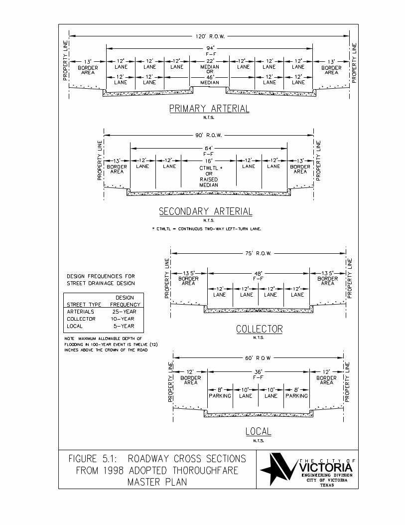

...\Documents\DCM\Figures.dgn 3/16/2007 2:06:46 AM

Local St. Collector St.
Secondary Arterial
St.
Primary Arterial
St.
0.1 9.5 17.6 19.0 20.5
0.2 13.4 24.9 26.9 29.0
0.3 16.5 30.5 32.9 35.5
0.4 19.0 35.3 38.0 41.0
0.5 21.3 39.4 42.5 45.8
0.6 23.3 43.2 46.6 50.2
0.7 25.2 46.6 50.3 54.2
0.8 26.9 49.9 53.8 58.0
0.9 28.5 52.9 57.0 61.5
1.0 30.1 55.7 60.1 64.8
1.5 36.8 68.3 73.6 79.4
2.0 42.5 78.8 85.0 91.6
3.0 52.1 96.5 104.1 112.2
4.0 60.1 111.5 120.2 129.6
5.0 67.2 124.6 134.4 144.9
Local St. Collector St.
Secondary Arterial
St.
Primary Arterial
St.
0.1 51.2 73.0 94.1 126.7
0.2 72.5 103.2 133.0 179.2
0.3 88.7 126.4 162.9 219.5
0.4 102.5 146.0 188.1 253.5
0.5 114.6 163.2 210.3 283.4
0.6 125.5 178.8 230.4 310.4
0.7 135.6 193.1 248.9 335.3
0.8 144.9 206.5 266.1 358.4
0.9 153.7 219.0 282.2 380.2
1.0 162.0 230.8 297.5 400.7
1.5 198.4 282.7 364.3 490.8
2.0 229.1 326.4 420.7 566.8
3.0 280.6 399.8 515.2 694.1
4.0 324.0 461.7 594.9 801.5
5.0 362.3 516.1 665.1 896.1
Slope
%
Street Capacities (cfs) with 6 Inches of Flow Above Curb
TABLE 5-1
HYDRAULIC CAPACITIES OF STANDARD STREET SECTIONS, CURB FULL
Slope
%
Street Capacities (cfs) Flowing Curb Full
TABLE 5-2
HYDRAULIC CAPACITY OF STANDARD STREET SECTIONS, 6 INCHES ABOVE CURB

Table 5-3
Minimum Allowable Slope for Storm Drains
Pipe Size
(Inches) Concrete Pipe Slope (ft/ft)
18 0.0018
21 0.0015
24 0.0013
27 0.0011
>30 0.0010

Table 5-4
Manning Roughness Coefficients, n
Manning's
n range
Manning's
n range
I. Closed conduits:
IV. Highway channels and swales with maintained vegetation (values
shown are for velocities of 2 and 6 f.p.s.):A. Concrete pipe 0.011-0.013 A. Depth of flow up to 0.7 foot:
B. Corrugated-metal pipe or pipe-arch: 1. Besmudagrass, Kentucky bluegrass, buffalograss:
1. 2 2/3 by ½-in. corrugation (riveted pipe):3
a. Mowed to 2 inches 0.07-0.045
a. Plain or fully coated 0.024 b. Length 44 inches 0.09-0.05b. Paved invert (range values are for 25 and 10 percent of
circumference paved): 2. Good stand, any grass:
(1) Flow full depth 0.021-0.018 a. Length about 12 inches 0.13-0.09(2) Flow 0.8 depth 0.021-0.016 b. Length about 24 inches 0.30-0.15(3) Flow 0.6 depth 0.019-0.013 3. Fair stand, any grass:
2. 6 by 2-in. corrugation (field bolted) 0.030 a. Length about 12 Inches 0.14-0.08C. Vitrified clay pipe 0.012-0.014 b. Length about 24 Inches 0.25-0.13D. Cast-Iron pipe, uncoated 0.013 B. Depth of flow 0.7-1.5 feet:
E. Steel pipe 0.009-0.011 1. Bermudagrass, Kentucky bluegrass, buffalograss:
F. Brick 0.014-0.017 a. Mowed to 2 inches 0.05-0.035G. Monolithic concrete: b. Length 4 to 6 inches 0.06-0.04
1. Wood forms, rough 0.015-0.017 2. Good stand, any grass:
2. Wood forms, smooth 0.012-0.014 a. Length about 12 inches 0.12-0.073. Steel forms 0.012-0.013 b. Length about 24 inches 0.20-0.10
H. Cemented rubble masonry walls: 3. Fair stand, any grass:
1. Concrete floor and top 0.017-0.020 a. Length about 12 inches 0.10-0.062. Natural floor 0.019-0.025 b. Length about 24 inches 0.17-0.09
I. Laminated treated wood 0.015-0.017J. Vitrified clay liner plates 0.015 V. Streets and expressway gutters:
A. Concrete gutter, troweled finish 0. 012
II. Open channels, lined4 (straight alinement):
5B. Asphalt pavement:
A. Concrete, with surfaces as indicated: 1. Smooth texture 0.0131. Formed, no finish 0.013-0.017 2. Rough texture 0.0162. Trowel finish 0.012-0.014 C. Concrete gutter with asphalt pavement:
3. Float finish 0.013-0.015 1. Smooth 0.0134. Float finish, some gravel on bottom 0.015-0.017 2. Rough 0.0155. Gunite, good section 0.016-0.019 D. Concrete pavement:
6. Gunite, wavy section 0.015-0.020 1. Float finish 0.014B. Concrete, bottom float finished, sides as indicated: 2. Broom finish 0.016
1. Dressed stone in mortar0.015-0.017 E. For gutters with small slope, where sediment may accumulate,
Increase above values of a by0.002
2. Random stone in mortar 0.017-0.020
3. Cement rubble masonry 0.020-0.025 VI. Natural stream channel:8
4. Cement rubble masonry, plastered 0.016-0.020 A. Minor streams’ (surface width at flood stage less than 100 ft.):
5. Dry rubble (riprap) 0.020-0.030 1. Fairly regular section:
C. Gravel bottom, sides as indicated: a. Some grass and weeds, little or no brush 0.030-0.035
1. Formed concrete0.017-0.020 b. Dense growth of weeds, depth of flow materially greater than
weed height0.035-0.05
2. Random stone in mortar 0.020-0.023 c. Some weeds, light brush on banks 0.035-0.053. Dry rubble (riprap) 0.021-0.033 d. Some weeds, heavy brush on banks 0.05-0.07
D. Brick 0.014-0.017 e. Some weeds, dense willows on banks 0.06-0.06
E. Asphalt:
f. For trees within channel, with branches submerged at high stage,
increase all above values by0.01-0.02
1. Smooth0.013 2. Irregular sections, with pools, slight channel meander; increase
values given in 1a-e about0.05-0.02
2. Rough0.016 3. Mountain streams, no vegetation in channel, banks usually steep,
trees and brush along banks sub merged at high stage:
F. Wood, planet clean 0.011-0.013 a. Bottom of gravel, cobbles, and few boulders 0.04-0.05G. Concrete-lined excavated rock: b. Bottom of cobbles, with large boulders 0.05-0.07
1. Good section 0.017-0.020 B. Flood plains (adjacent to natural streams):
2. Irregular section 0.022-0.027 1. Pasture, no brush:
a. Short grass 0.030-0.035
III. Open channels, excavated4 (straight alignment,5 natural lining): b. High grass0.035-0.05
A. Earth, uniform section: 2. Cultivated areas:
1. Clean, recently completed 0.016-0.018 a. No crop 0.03-0.042. Clean, alter weathering 0.018-0.020 b. Mature row crops 0.035-0.0453. With short grass, few weeds 0.022-0.027 c. Mature field crops 0.04-0.054. In gravelly soil, uniform section, clean 0.022-0.025 3. Heavy weeds, scattered brush 0.05-0.07
B. Earth, fairly uniform section: 4. Light brush and trees:
1. No vegetation 0.022-0.025 a. Winter 0.05-0.062. Grass, some weeds 0.025-0.030 b. Summer 0.06-0.063. Dense weeds or aquatic plants in deep channels 0.030-0.035 5. Medium to dense brush:
4. Sides clean, gravel bottom 0.025-0.030 a. Winter 0. 07-0.115. Sides clean, cobble bottom 0.030-0.040 b. Summer 0. 10-0.16
C. Dragline excavated or dredged: 6. Dense willows, summer, not bent over by current 0.15-0.201. No vegetation 0.028-0.033 7. Cleared land with tree stumps. 100-150 per acre:
2. Light brush on banks 0.035-0.050 a. No sprouts 0.04-0.05D. Rock: b. With heavy growth of sprouts 0.06-0.06
1. Based on design section 0.035 8. Heavy stand of timber, a few down trees, little undergrowth:
2. Based on actual mean section: a. Flood depth below branches 0.10-0.12a. Smooth and uniform 0.035-0.040 b. Flood depth roaches branches 0.12-0.16b. Jagged and irregular 0.040-0.045
H. Channels not maintained, weeds and brush uncut:
1. Dense weeds, high as flow depth 0.08-0.122. Clean bottom, brush on sides 0.05-0.083. Clean bottom, brush on sides, highest stage of flow 0.07-0.11
4. Dense brush, high stage 0.10-0.14
C. Major streams (surface width at flood stage more than 100 ft.):
Manning's n is usually less than for minor streams of similar description due
to less effective resistance offered by irregular banks or vegetation on
banks. Values of n may be somewhat reduced. The value of n for larger
streams of regular section, with no boulders or brush, may be in the range
of
0.038-0.033
441184/030203 6-1
6.0 STORM WATER DETENTION
6.1 APPLICATION OF DETENTION
Refer to Section 2.0 for policy statements governing situations that necessitate the use of storm water
detention facilities.
6.2 CALCULATION OF DETENTION VOLUME
A flow routing analysis using detailed hydrographs must be applied for all detention pond designs. The
Soil Conservation Service hydrologic methods (available in TR-20, HEC-1 and HEC-HMS) and the
Hydrologic Engineering Center (HEC) hydrologic methods may be used. The engineer may use other
methods but must have their acceptability approved by the City Engineer.
A. The required volume must be such that the peak flow before the development must be reasonably
duplicated after the development, or in cases where the existing site results in a potential or real
threat to existing structures; the new development must provide detention in accordance with
Section 2.2.8.
B. Detention volume for redevelopment areas is calculated on the basis of the amount of area of
increased impervious cover.
C. Private parking areas, private streets, and private storm drains may be used for detention provided
the maximum depth of flooding does not exceed 9 inches directly over the inlet and paved
parking areas are clearly marked.
6.3 CALCULATION OF OUTLET SIZE
A. In the case of detention facility discharge into an existing storm drain line or existing City of
Victoria ditch the following shall apply:
1. Maximum pool elevation at or below the design hydraulic grade at the outfall - The discharge
line shall be sized for the Design Storm with the outfall pipe flowing full.
2. Maximum pool elevation at or above the hydraulic grade at the outfall - Provide a reducer or
restrictor pipe to be constructed inside the discharge line. The discharge line shall be sized
for the Design Storm with the outfall pipe flowing full.
B. Reducer or Restrictor Pipes shall be sized as follows:
1. The reducer or restrictor will be sized for the undeveloped rate of discharge up to a maximum
release of 0.5 cfs per acre.

448153 6-2
2. Use the following equations to calculate the required outflow orifice:
Q = CA (2gh)1/2
D = Q1/2
/ 2.25 h1/4
Where Q = outflow discharge in cfs
C = coefficient (Use 0.6)
h = water surface differential in feet (head on the orifice)
D = orifice diameter in feet
A = cross sectional area of the orifice in square feet
3. The restrictor orifice shall be either of the required diameter or of the equivalent cross-
sectional area. The orifice diameter (D) shall be a minimum of 6 inches.
C. In addition to a pipe outlet, the detention basin should be provided with a gravity spillway that
will protect adjacent and upstream structures from flooding should the detention basin be
overtopped.
6.4 OWNERSHIP AND EASEMENTS
A. Private Facilities
1. Pump discharges into a roadside ditch shall require the submittal of pump specifications on
the design drawings.
2. The City reserves the right to prohibit the use of pump discharges where their use may
aggravate flooding in the public right-of-way.
3. Responsibility for maintenance of detention facilities must be indicated by letter submitted to
the City Engineer as part of the design review.
4. All private properties being served by a detention facility must have drainage access to the
facility.
5. No public properties should drain into a private detention facility.
6. A private maintenance agreement must be provided when multiple tracts are being served.
B. Public Facilities
1. The City will only accept facilities for maintenance in cases where public drainage is
provided.

448153 6-3
2. The City will require a maintenance work area of 20-foot width surrounding the extent of the
detention area. Public rights-of-way or permanent access easements may be included as a
portion of this 20-foot width.
3. A dedication of easement must be provided by plat or by separate instrument.
4. Proper dedication of public access to the detention pond must be shown on the plat or by
separate instrument. This includes permanent access easements with overlapping public
utility easements.

441184/030203 7-1
7.0 STORM DRAINAGE MASTER PLAN
The Storm Drainage Master Plan (SDMP) encompassed the City's 100-square mile drainage area east of
the Guadalupe River and includes. The major watersheds in this area include Lone Tree Creek, Spring
Creek, Whispering Creek, North Outfall, Jim Branch Creek, West Outfall, Mercado creek and their
tributaries (US Highway 77 Outfall, Mockingbird Outfall, South Outfall, and Second Street).
An integral part of the storm drainage master plan development involved the identification and location of
problem areas, the gathering of pertinent data for the areas identified, the hydrologic/hydraulic analysis of
the areas, the screening and evaluation of storm water structural and non-structural control measures and
the selection of recommended control measures (or a combination thereof) for the individual problem
areas and watersheds. This effort was organized and carried out on a watershed and subwatershed basis
for various reasons including the interactions of the hydrologic and hydraulic systems within a watershed.
Care was taken to avoid creating new problems while solving the original problem. In that regard,
drainage solutions were generally be developed working from downstream to upstream.
The SDMP included the development of a series of models for hydrologic and hydraulic (open and closed
system) analyses. These models were created for the existing condition hydrology, the future condition
hydrology, the existing system hydraulics, and a first estimate of the future system hydraulics. As these
individual aspects of the City drainage were combined with each other, the following three scenarios were
generated and included in the SDMP analysis:
1. Present land use and Present drainage infrastructure conditions (the "present/present" condition),
2. Future land use and Present drainage infrastructure conditions (the "future/present" condition), and
3. Future land use and Future drainage infrastructure conditions (the "future/future" condition).
Separate sets of hydrologic and hydraulic models were generated for each of the three conditions.
These models were used to evaluate the existing open channel and closed systems and to develop
recommendations for improvements to these systems. All recommended improvements were based on
the future condition hydrology.

448153 8-1
8.0 GLOSSARY
A. Conduit - Any open or closed device for conveying flowing water.
B. Drainage Area Map - Area map of watershed which is subdivided to show each area
served by each subsystem.
C. Hydraulic Grade Line (HGL) - A line representing the pressure head available at any
given point within the drainage system.
D. Redevelopment - A change in land use that alters the impervious cover from one type of
development to either the same type or another type, and takes advantage of the existing
infrastructure in place as a drainage outlet.
E. In-Fill Development - Development of open tracts of land in areas where the storm
drainage infrastructure is already in place and takes advantage of the existing
infrastructure as a drainage outlet.
F. Rational Formula - A method for calculating the peak runoff for a storm drain system
using the following equation for runoff:
G. Design Storm Event - The rainfall intensity upon which the drainage facility will be
sized.
H. Rainfall Frequency - The probability of a rainfall event of defined characteristics
occurring in any given year. Information on rainfall frequency is published by the
National Weather Service. For the purpose of storm drainage design, the following
frequencies are applicable:
1. 2-year frequency - a rainfall intensity having a 50% probability of occurrence in any given
year, or nominally likely to occur once every two years.
2. 3-year frequency - a rainfall intensity having a 33% probability of occurrence in any given
year, or nominally likely to occur once every three years.
3. 5-year frequency - a rainfall intensity having a 20% probability of occurrence in any given
year, or nominally likely to occur once every five years.
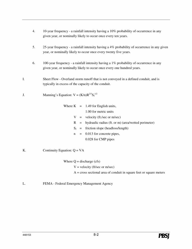
448153 8-2
4. 10-year frequency - a rainfall intensity having a 10% probability of occurrence in any
given year, or nominally likely to occur once every ten years.
5. 25-year frequency - a rainfall intensity having a 4% probability of occurrence in any given
year, or nominally likely to occur once every twenty five years.
6. 100-year frequency - a rainfall intensity having a 1% probability of occurrence in any
given year, or nominally likely to occur once every one hundred years.
I. Sheet Flow - Overland storm runoff that is not conveyed in a defined conduit, and is
typically in excess of the capacity of the conduit.
J. Manning’s Equation: V = (K/n)R2/3
Sf1/2
Where K = 1.49 for English units,
1.00 for metric units
V = velocity (ft./sec or m/sec)
R = hydraulic radius (ft. or m) (area/wetted perimeter)
Sf = friction slope (headloss/length)
n = 0.013 for concrete pipes,
0.028 for CMP pipes
K. Continuity Equation: Q = VA
Where Q = discharge (cfs)
V = velocity (ft/sec or m/sec)
A = cross sectional area of conduit in square feet or square meters
L. FEMA - Federal Emergency Management Agency
441184/030203 9-1
9.0 BIBLIOGRAPHY
Arkansas State Highway and Transportation, Drainage Manual, 1982.
Brater, E.F., and H.W. King, Handbook of Hydraulics, McGraw Hill, 6th Edition, 1976.
Brazoria County, Drainage Criteria Manual, Draft, 1990.
Chow, Ven Te, Open Channel Hydraulics, McGraw Hill, 1959.
Chow, Ven Te, Handbook of Applied Hydrology, McGraw Hill, 1964.
City of Austin, Drainage Criteria Manual, 1989.
City of Fayetteville, Arkansas, Drainage Criteria Manual, Draft, 1995.
City of Fort Worth, Public Works Department, Storm Drainage Criteria and Design Manual, 1967.
City of Houston, Department of Public Works and Engineering, Design Manual for Wastewater
Collection Systems, Water Lines, Storm Drainage and Street Paving, 1996.
City of Longview, Texas, Drainage Criteria and Erosion Control Manual.
City of Shreveport, Louisiana, Department of Public Works, Design Criteria for Storm Sewers and
Appurtenances, 1975.
City of Victoria, Texas, Storm Drainage Design Manual for the City of Victoria, Texas, 1980.
City of Victoria Flood-Prone Areas, the Code of Ordinances
City of Waco, Texas, Engineering Department, Storm Drainage Design Manual, 1959.
Davis, C.V. and K.E. Sorensen, Handbook of Applied Hydraulics, McGraw Hill, 3rd Edition, 1969.
Fort Bend County Drainage District, Drainage Criteria Manual for Fort Bend County, Texas, 1987.

448153 9-2
Harris County Flood Control District, Criteria Manual for the Design of Flood Control and Drainage
Facilities in Harris County, Texas, 1984.
Hjelmfelt, A.T. and J. Cassidy, Hydrology for Engineers and Planners, Iowa State University Press, 1975.
Leopold, Luna. A View of the River, Harvard University Press, 1994.
Linsley, R.K., M.A. Kohler, and J.L.H. Paulhus, Hydrology for Engineers, McGraw Hill, 1958.
Montgomery County, Drainage Criteria Manual for Montgomery County, Texas, 1989.
National Weather Service , TP-40 Rainfall Frequency Atlas of the United States
National Weather Service , Hydro-35; 5-to-60 Minute Precipitation Duration of the Eastern and Central
United States
Rosgen, Dave, Applied River Morphology, Wildland Hydrology, 1996.
Texas Department of Transportation, Hydraulic Design Manual, 2004.
U.S. Army Corps of Engineers, Engineer Manuals (EM) on hydrology and hydraulics,
http://www.usace.army.mil/publications/eng-manuals/em.htm.
U.S. Department of Agriculture, Predicting Soil Erosion by Water, A Guide to Conservation Planning
with the Revised Universal Soil Loss Equation (RUSLE), 1997.
U.S. Department of Agriculture, Agricultural Research Service, Agriculture Handbook No. 667, Stability
Design of Grass-Lined Open Channels, 1987.
U.S. Department of Interior, Bureau of Reclamation, Hydraulic and Excavation Tables, 11th Ed, 1957.
U.S. Department of Interior, Bureau of Reclamation, Design of Small Dams, 1973.
U.S. Department of Interior, Bureau of Reclamation, Hydraulic Design of Stilling Basins and Energy
Dissipators, Engineering Monograph No. 25, 1978.

448153 9-3
U.S. Department of Transportation, Federal Highway Administration, Hydraulic Charts for the Selection
of Highway Culverts, Hydraulic Engineering Circular No. 5, 1980.
U.S. Department of Transportation, Federal Highway Administration, Hydraulic Design of Energy
Dissipators for Culverts and Channels, Hydraulic Engineering Circular No. 14, 1983.
U.S. Department of Transportation, Federal Highway Administration, Hydraulic Design of Highway
Culverts, Hydraulic Design Series No. 5, 2005.
U.S. Department of Transportation, Federal Highway Administration, Hydraulic Design of Improved
Inlets for Culverts, Hydraulic Engineering Circular No. 13, 1972.