city of gulfport construc on standards · fire hydrant assemblies ... cross connection control for...
TRANSCRIPT

City of Gulfport
Construc on Standards
City of Gulfport Engineering Department 4050 Hewes Avenue Gulfport, MS 39507
(228) 868-5815
City of Gulfport Public Works Department 4050 Hewes Avenue Gulfport, MS 39507
(228) 868-5740
May, 2015 Rev. August, 2015

City of Gulfport Table of Contents - 1 AUGUST, 2015 Standard Specifications
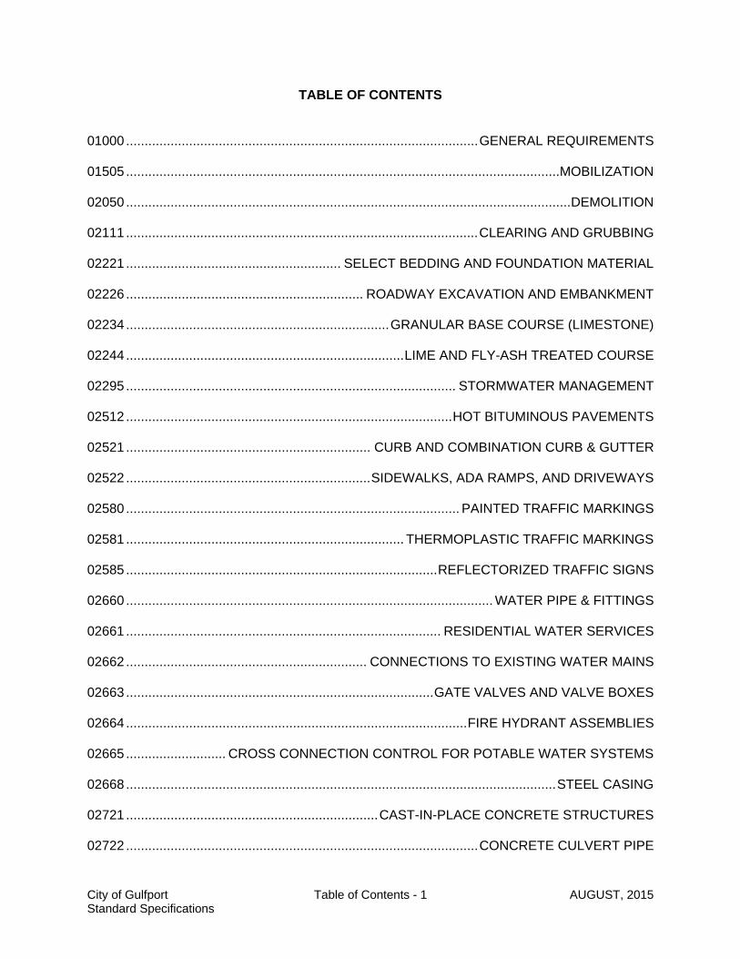
TABLE OF CONTENTS 01000 ............................................................................................... GENERAL REQUIREMENTS 01505 ..................................................................................................................... MOBILIZATION 02050 ........................................................................................................................ DEMOLITION 02111 ............................................................................................... CLEARING AND GRUBBING 02221 .......................................................... SELECT BEDDING AND FOUNDATION MATERIAL 02226 ................................................................ ROADWAY EXCAVATION AND EMBANKMENT 02234 ....................................................................... GRANULAR BASE COURSE (LIMESTONE) 02244 ........................................................................... LIME AND FLY-ASH TREATED COURSE 02295 ......................................................................................... STORMWATER MANAGEMENT 02512 ........................................................................................ HOT BITUMINOUS PAVEMENTS 02521 .................................................................. CURB AND COMBINATION CURB & GUTTER 02522 .................................................................. SIDEWALKS, ADA RAMPS, AND DRIVEWAYS 02580 .......................................................................................... PAINTED TRAFFIC MARKINGS 02581 ........................................................................... THERMOPLASTIC TRAFFIC MARKINGS 02585 .................................................................................... REFLECTORIZED TRAFFIC SIGNS 02660 ................................................................................................... WATER PIPE & FITTINGS 02661 ..................................................................................... RESIDENTIAL WATER SERVICES 02662 ................................................................. CONNECTIONS TO EXISTING WATER MAINS 02663 ................................................................................... GATE VALVES AND VALVE BOXES 02664 ............................................................................................ FIRE HYDRANT ASSEMBLIES 02665 ........................... CROSS CONNECTION CONTROL FOR POTABLE WATER SYSTEMS 02668 .................................................................................................................... STEEL CASING 02721 .................................................................... CAST-IN-PLACE CONCRETE STRUCTURES 02722 ............................................................................................... CONCRETE CULVERT PIPE

City of Gulfport Table of Contents - 2 AUGUST, 2015 Standard Specifications
02723 ................................................................ HIGH DENSITY POLYETHYLENE PIPE (HDPE) 02730 .................................................................................................... GRAVITY SEWER PIPES 02731 .......................................................................................................................... MANHOLES 02732 ................................................................................ PRECAST SEWAGE PUMP STATION 02733 .............................................................. PRESSURE SEWER MAIN & APPURTENANCES 02734 ................................................................. AIR VALVES FOR PRESSURE SEWER MAINS 02735 .................................. CLEANING AND INSPECTION OF GRAVITY SANITARY SEWERS 02736 .......................................................................................... CURED-IN-PLACE PIPE (CIPP) 02737 .......................................................................................... SEWER MAIN PIPE-BURSTING 02738 ............................................................................... SEWER MANHOLE REHABILITATION 02739 ................................................................................. SANITARY SEWER POINT REPAIRS 02740 .................................................................................. SEWER SYSTEM SMOKE TESTING 02752 ................................................................................................................... STONE RIPRAP 02762 ......................................................................... INSPECTION OF UNDERGROUND PIPES 02931 ................................................................................................... PLANT ESTABLISHMENT 02935 .............................................................................................. MAINTENANCE OF TRAFFIC APPENDIX A .............................................................. STANDARD OPERATING PROCEDURES

01000 ............................................................................................. GENERAL REQUIREMENTS 1.0 SCOPE OF WORK 1.0.1 MDOT Specifications. Where this term is used within these technical specifications, it
shall be construed to mean the current edition of the Mississippi Department of Transportation Specifications for Road and Bridge Construction.
1.1 Abbreviations
Where the following abbreviations and definitions are used in these specifications or other contract documents, they are to be construed the same as the respective expression.
AASHTO American Association of State Highway Transportation Officials ACI American Concrete Institute ADA American Disabilities Act AISC American Institute of Steel Construction ANSI American National Standards Institute AREA American Railway Engineering Association
ASTM American Society for Testing and Materials AWWA American Water Works Association CRMP Coastal Resource Management Program CRSI Concrete Reinforcing Steel Institute EPA Environmental Protection Agency LCNOI Large Construction Notice of Intent (Required for projects disturbing 5.0 or
more acres) MDMR Mississippi Department of Marine Resources
MDOT Mississippi Department of Transportation MUTCD Manual on Uniform Traffic Control Devices NAPA National Asphalt Pavement Association NBC National Building Code NEC National Electric Code
SCNOI Small Construction Notice of Intent (Required for projects disturbing 1.0 to 5.0 acres)
SWPPP Stormwater Pollution Prevention Plan 2.0 PERMITS REQUIRED 2.1 Regulatory and environmental permits may be required, depending on the nature and
location of the construction work. 2.2 In general, permitting is generally required for the following types of work: (NOTE: This list is not intended to be all-inclusive, and is for general guidance.)
City of Gulfport 01000 - 1 May, 2015 Standard Specifications
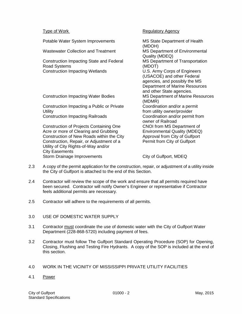
Type of Work Regulatory Agency Potable Water System Improvements MS State Department of Health
(MDOH) Wastewater Collection and Treatment MS Department of Environmental
Quality (MDEQ) Construction Impacting State and Federal MS Department of Transportation
Road Systems (MDOT) Construction Impacting Wetlands U.S. Army Corps of Engineers
(USACOE) and other Federal agencies, and possibly the MS Department of Marine Resources and other State agencies.
Construction Impacting Water Bodies MS Department of Marine Resources (MDMR)
Construction Impacting a Public or Private Coordination and/or a permit Utility from utility owner/provider Construction Impacting Railroads Coordination and/or permit from
owner of Railroad Construction of Projects Containing One CNOI from MS Department of Acre or more of Clearing and Grubbing Environmental Quality (MDEQ) Construction of New Roads within the City Approval from City of Gulfport Construction, Repair, or Adjustment of a Permit from City of Gulfport Utility of City Rights-of-Way and/or City Easements Storm Drainage Improvements City of Gulfport, MDEQ 2.3 A copy of the permit application for the construction, repair, or adjustment of a utility inside
the City of Gulfport is attached to the end of this Section.
2.4 Contractor will review the scope of the work and ensure that all permits required have been secured. Contractor will notify Owner’s Engineer or representative if Contractor feels additional permits are necessary.
2.5 Contractor will adhere to the requirements of all permits. 3.0 USE OF DOMESTIC WATER SUPPLY 3.1 Contractor must coordinate the use of domestic water with the City of Gulfport Water
Department (228-868-5720) including payment of fees. 3.2 Contractor must follow The Gulfport Standard Operating Procedure (SOP) for Opening,
Closing, Flushing and Testing Fire Hydrants. A copy of the SOP is included at the end of this section.
4.0 WORK IN THE VICINITY OF MISSISSIPPI PRIVATE UTILITY FACILITIES 4.1 Power
City of Gulfport 01000 - 2 May, 2015 Standard Specifications

4.1.1 Contractor is advised that Mississippi Power Company (MSPCo) will charge Contractors a fee to recover costs associated with services such as holding poles when excavation may affect the stability of the pole line, and/or covering power lines with insulated blankets when overhead work will occur in the vicinity of overhead lines. If this project warrants MSPCo involvement, Contractors are advised to contact MSPCo to obtain a cost estimate and include sufficient funds in their bid. Contractors are further advised that the Owner will not accept responsibility for these costs outside of the Contract unless specifically stated in these documents.
4.1.2 Coast Electric Power Association (CEPA) 4.1.2 Work in the vicinity of CEPA facilities shall be coordinated with CEPA at (877) 769-2372 or
(228) 832-1761. If the project warrants CEPA’s involvement, Contractors are advised to contact CEPA to obtain a cost estimate for hold poles, moving facilities and include sufficient funds in their bid. Contractors are further advised that the Owner will not accept responsibility for these costs outside of the Contract unless specifically stated in these documents.
4.2 Natural Gas 4.2.1 Work in the vicinity of natural gas mains or pumping stations shall be coordinated with
Centerpoint Energy at (800) 371-5417, Gulf South Pipeline at (832) 453-1813. Contractors shall fully coordinate their work including required clearances between new construction and existing natural gas mains with the companies listed above. If this project warrants any natural gas company involvement, Contractors are advised to contact Centerpoint to obtain a cost estimate and include sufficient funds in their bid. Contractors are further advised that the Owner will not accept responsibility for these costs outside of the Contract unless specifically stated in these documents.
4.3 Communications
Work in the vicinity of communications facilities shall be coordinated with one or more of the following:
Bell South (228) 557-6123 AT&T (228) 374-5595
If the project warrants any communications company involvement, Contractors are advised to contact the communications facility to obtain a cost estimate and include sufficient funds in their bid. Contractors are further advised that the Owner will not accept responsibility for these costs outside of the Contract unless specifically stated in these documents.
4.4 Cable Television
Work in the vicinity of cable television facilities shall be coordinated with Cable One at (228) 864-1506. If this project warrants cable television company involvement, Contractors are advised to contact the communications facility to obtain a cost estimate and include sufficient funds in their bid. Contractors are further advised that the Owner will not accept responsibility for these costs outside of the Contract unless specifically stated in these documents.
City of Gulfport 01000 - 3 May, 2015 Standard Specifications

01505 .................................................................................................................. MOBILIZATION 1.0 SCOPE OF WORK 1.1 This work shall consist of preparatory operations, including, but not limited to, those
necessary to the cost and movement of labor, material, equipment and incidentals to the project site; and for all other work operations which must be performed or costs included prior to beginning work on the various items on the project site.
2.0 MATERIALS 2.1 None 3.0 CONSTRUCTION REQUIREMENTS 3.1 None 4.0 METHOD OF MEASUREMENT 4.1 Partial payments will be made as the work progresses in accordance with the following
schedule: 4.1.1 When 5 percent of the original contract amount is earned from other bid items, 50 percent
of the amount bid for mobilization, or 2.5 percent of the original contract amount, whichever is lesser, will be paid.
4.1.2 When 10 percent of the original contract amount is earned from other bid items, 100
percent of the amount bid for mobilization, or 5 percent of the original contract amount, whichever is lesser, will be paid.
4.1.3 Upon completion of all work on the project, payment of any amount bid for mobilization in
excess of 5 percent of the original contract amount, will be paid. 4.1.4 The total sum of all payments shall not exceed the original contract amount bid for
mobilization, regardless of the fact that Contractor may have, for any reason, shut down his work on the project or moved equipment away from the project and then back again.
5.0 PAYMENT 5.1 Payment shall be made in accordance with Pay Item No. 01505-A Mobilization $ per lump sum
City of Gulfport 01505 - 1 May, 2015 Standard Specifications

02050 ..................................................................................................................... DEMOLITION 1.0 SCOPE OF WORK 1.1 This work shall consist of the demolition, removal, and satisfactory disposal of structures,
foundations, pavement, curb, culverts, utilities, and any other items which are designated in the plans to be removed, or necessary to construct the project.
1.2 This work shall also consist of furnishing all labor, equipment and materials and
performing all operations in connection with the saw cutting of concrete and asphalt surfaces, as indicated on the plans, as determined in the field, and as specified herein.
1.3 This work shall also consist of salvage and delivery to Owner of items deemed to be
salvageable. 1.4 Specified Elsewhere: Clearing and Grubbing — 02111 2.0 MATERIALS 2.1 None. 3.0 CONSTRUCTION REQUIREMENTS 3.1 Contractor shall obtain and pay for all required demolition permits and shall conform with
all Local, State, and Federal laws and codes. 3.2 Contractor shall raze or remove and satisfactorily dispose of all items designed to be
removed. 3.3 All forming materials will be removed before backfilling, no wood or biodegradable
materials shall remain or be buried on site. 3.4 Contractor shall preserve and protect all structures, sidewalks, driveways, fences, trees,
private utilities, and all other items which are to remain. 3.5 Contractor shall conform to applicable codes, safety of adjacent structures, dust control,
erosion control, and off-site disposal locations and notify any affected utility companies before starting work. Contractor shall not burn or bury material on site.
3.5 Contractor shall not close or obstruct roadways, sidewalks or hydrants, without proper
permission and/or permits as may be required by the City. 3.6 Contractor shall conform to applicable regulatory procedures when discovering hazardous
or contaminated materials and report it immediately to the City Engineer. 3.7 In areas of the project where existing concrete surfaces must be protected and clean
match lines maintained between an existing concrete surface and a new concrete curb, driveway, sidewalk, etc., the existing concrete surface shall be saw cut the full thickness of
City of Gulfport 02050 - 1 May, 2015 Standard Specifications
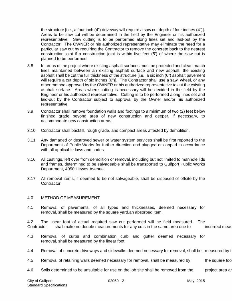
the structure [i.e., a four inch (4”) driveway will require a saw cut depth of four inches (4”)]. Areas to be saw cut will be determined in the field by the Engineer or his authorized representative. Saw cutting is to be performed along lines set and laid-out by the Contractor. The OWNER or his authorized representative may eliminate the need for a particular saw cut by requiring the Contractor to remove the concrete back to the nearest construction joint if a construction joint is within five feet (5’) of where the saw cut is planned to be performed.
3.8 In areas of the project where existing asphalt surfaces must be protected and clean match lines maintained between an existing asphalt surface and new asphalt, the existing asphalt shall be cut the full thickness of the structure [i.e., a six inch (6”) asphalt pavement will require a cut depth of six inches (6”)]. The Contractor shall use a saw, wheel, or any other method approved by the OWNER or his authorized representative to cut the existing asphalt surface. Areas where cutting is necessary will be decided in the field by the Engineer or his authorized representative. Cutting is to be performed along lines set and laid-out by the Contractor subject to approval by the Owner and/or his authorized representative.
3.9 Contractor shall remove foundation walls and footings to a minimum of two (2) feet below finished grade beyond area of new construction and deeper, if necessary, to accommodate new construction areas.
3.10 Contractor shall backfill, rough grade, and compact areas affected by demolition. 3.11 Any damaged or destroyed sewer or water system services shall be first reported to the
Department of Public Works for further direction and plugged or capped in accordance with all applicable laws and codes.
3.16 All castings, left over from demolition or removal, including but not limited to manhole lids
and frames, determined to be salvageable shall be transported to Gulfport Public Works Department, 4050 Hewes Avenue.
3.17 All removal items, if deemed to be not salvageable, shall be disposed of offsite by the
Contractor. 4.0 METHOD OF MEASUREMENT 4.1 Removal of pavements, of all types and thicknesses, deemed necessary for removal, shall be measured by the square yard.an absorbed item. 4.2 The linear foot of actual required saw cut performed will be field measured. The Contractor shall make no double measurements for any cuts in the same area due to incorrect meas 4.3 Removal of curbs and combination curb and gutter deemed necessary for removal, shall be measured by the linear foot. 4.4 Removal of concrete driveways and sidewalks deemed necessary for removal, shall be measured by th 4.5 Removal of retaining walls deemed necessary for removal, shall be measured by the square foot 4.6 Soils determined to be unsuitable for use on the job site shall be removed from the project area an
City of Gulfport 02050 - 2 May, 2015 Standard Specifications

4.7 Removal of existing sewer manholes shall be included in the cost of new manholes measured per e 4.8 Removal of existing sewer main, 24” and smaller, shall be measured by the linear foot. 4.9 Removal of existing drainage pipes shall be measured by the linear foot of pipe removed. 5.0 PAYMENT 5.1 Payments shall be made under Pay Item No. 02050-A Removal of Pavement (All Types and Thicknesses) $ per square yard 02050-B Saw Cut (All Types and Thicknesses) $ per linear foot 02050-C Removal Curb and Gutter $ per linear foot 02050-D Removal of Concrete Driveway $ per square yard 02050-E Removal of Sidewalk $ per square yard 02050-F Removal of Retaining Walls $ per square foot 02050-G Removal of Unsuitable Soils From Job Site $ per cubic yard
02050-H Removal of Sewer Manholes $ per each 02050-I Remove Existing Sewer Pipes
City of Gulfport 02050 - 3 May, 2015 Standard Specifications

(24” and smaller) $ per linear foot 02050-J Removal of RCP 12”-23” $ per linear foot 02050-K Removal of RCP 24”-36” $ per linear foot
City of Gulfport 02050 - 4 May, 2015 Standard Specifications

02111 ............................................................................................ CLEARING AND GRUBBING 1.0 SCOPE OF WORK 1.1 This work shall consist of all labor, materials, and equipment for the clearing, grubbing,
removing, and proper disposal of all things within the limits of the site or right-of-way, except things designated to remain or to be removed by others. This work shall also include the preservation from injury or defacement of trees, vegetation, objects, or materials designated to remain or to be salvaged.
1.2 Specified Elsewhere: Excavation and Embankment — 02226 2.0 MATERIALS 2.1 None. 3.0 CONSTRUCTION REQUIREMENTS 3.1 The property lines and/or right-of-way lines and all trees, shrubs, plants, and other things
designated to remain are shown on the plans. 3.2 Surface objects, trees, stumps, roots, and other protruding or underground obstructions,
not designated to remain, shall be cleared and grubbed (including mowing, if required). Undisturbed stumps and roots and non-perishable solid objects which will be a minimum of three (3) feet below subgrade or slope of embankment may be left when authorized by Engineer.
3.3 All operations shall be conducted in such a manner as to prevent damage to anything that
is to remain on the right-of-way or to adjacent property. 3.4 Burning or burying of perishable material will not be allowed. Materials and debris shall be
removed from the site or right-of-way and disposed of at an approved location obtained by Contractor.
3.5 Low hanging and unsound or unsightly branches on trees or shrubs designated to remain
shall be removed as directed. Branches of trees extending over the roadway shall be trimmed to give a clear height of at least twenty (20) feet above the roadway surface. All trimming shall be done by skilled workmen and in accordance with good tree surgery practices. An approved asphaltum base paint prepared specifically for tree surgery shall be furnished and applied by Contractor to cut or scarred surfaces on trees or shrubs selected to remain.
3.6 Contractor shall conform to applicable regulatory procedures when discovering hazardous
contaminated materials and possible historic / archeological finds.
City of Gulfport 02111 - 1 May, 2015 Standard Specifications

4.0 METHOD OF MEASUREMENT 4.1 Clearing and Grubbing shall be paid for at the contract price per acre (plan measure),
which shall be full compensation for satisfactorily completing the work as specified. 5.0 PAYMENT 5.1 Payment will be made under Pay Item No. 02111-A Clearing and Grubbing $ per acre (PM)
City of Gulfport 02111 - 2 May, 2015 Standard Specifications

02221 ............................................................. SELECT BEDDING & FOUNDATION MATERIAL 1.0 SCOPE OF WORK 1.1 This work shall consist of all labor, materials, and equipment required to construct a
compacted embedment or foundation, for pipeline construction, to the lines and dimensions indicated in the plans and as specified and authorized herein.
2.0 MATERIALS 2.1 Select Bedding Material shall consist of clean sand with less than 10 percent passing the
No. 200 sieve. 2.2 Select Foundation Material shall consist of a manufactured mixture of 65 percent crushed
limestone (#610 gradation) and 35 percent sand (less than 10 percent passing the No. 200 sieve).
3.0 CONSTRUCTION REQUIREMENTS 3.1 This work shall conform to the widths and depths as shown on the plans.
3.2 Select bedding and foundation material shall be installed in generally parallel layers, and
each layer will not exceed 9" in thickness unless otherwise specified. 3.2.1 In areas where select bedding and foundation materials are installed, the material will be
compacted to 95% percent of Standard Proctor Maximum dry density per ASTM 698. 4.0 METHOD OF MEASUREMENT 4.1 Select Bedding Material and Select Foundation Material will be measured by the cubic
yard, plan measure. The volume will be determined by the allowable trench width multiplied by the allowable depth (less the area of the pipe) as shown on the plans multiplied by the authorized trench length.
5.0 PAYMENT 5.1 Payment will be made in accordance with Pay Item No.
02221-A Select Bedding Material $ per cubic yard (PM) 02221-B Select Foundation Material $ per cubic yard (PM)
City of Gulfport 02221 - 1 May, 2015 Standard Specifications

02226 .............................................................. ROADWAY EXCAVATION AND EMBANKMENT 1.0 SCOPE OF WORK 1.1 This work shall consist of excavation and embankment required for roadway
construction and includes the preparation of subgrade and foundations, the furnishing of borrow materials, the construction of embankments, other utilization or disposal of materials excavated, and the compaction and dressing of excavated areas and embankments.
1.2 A Stormwater Pollution Prevention Plan (SWPPP) shall be approved by the
Gulfport Engineering Department per Section 02295 (examples can be provided if needed).
1.3 DEFINITIONS 1.3.1 Excess excavation will consist of the excavation, removal, and disposal of all
soils that are determined by Project Engineer to be unsatisfactory foundation material, to a point beyond the excavation limits shown on the plans. Contractor shall provide, at his own expense, the location for excess excavation disposal.
Note: Check with the Department of Public Works as this material may be
useable in other locations within the City. 1.3.2 Borrow material will consist of approved material required for the construction of
embankments and the replacement of unsuitable material which has been removed. Contractor shall make arrangements for obtaining borrow material and shall pay all costs involved.
1.3.3 Stripping excavation shall consist of the excavation, removal, and stockpiling of
the upper six (6) inches of organic material within the right-of-way, which material will later be processed by Contractor, without additional compensation, as plating for embankments.
1.3.4 Unclassified excavation shall consist of all excavation and processing,
stockpiling, or disposal of all materials of whatever character encountered on the work, except for those for which additional pay items are provided. Processing shall include haul, drying if required, placing, and compacting of suitable excavated materials to areas requiring backfill material. Stockpiling, if allowed, shall consist of the hauling and spreading of all suitable surplus unclassified excavation as shown on the plans. Disposal shall include haul for proper disposal of all unclassified excavation unsuitable for backfill material, as deemed by Project Engineer. Contractor shall provide, at his own expense, the location for the disposal of unsuitable material.
1.4 SPECIFIED ELSEWHERE. 02295 – Erosion Control
City of Gulfport 02226 - 1 May, 2015 Standard Specifications

2.0 MATERIALS 2.1 BORROW MATERIAL – TYPE A AND B. Granular material meeting the Class 9,
Group C, requirements of the MDOT Specifications. 2.2 BORROW MATERIAL – TYPE C. Clean sand with less than ten percent (10%)
passing the No. 200 sieve. 3.0 CONSTRUCTION REQUIREMENTS 3.1 GENERAL. Excavation and embankment operations may be started by
Contractor at the location and in sequence approved by Engineer when:
(1) sufficient clearing and grubbing has been completed and accepted;
(2) the work has been cross sectioned and slope staked; (3) installation of required pipes, culverts, and approved backfills are
complete;
(4) the site has been prepared in accordance with these specifications;
(5) Contractor has informed himself as to the proper haul and disposal of material.
3.1.1 Where plating is contemplated, either in cut or fill sections, appropriate
adjustment shall be made by Contractor in the graded section during construction so that the finished section after plating will conform within reasonable tolerances to the typical sections shown on the plans.
3.1.2 Contractor shall not excavate beyond the dimensions and elevations established
or approved and shall not move any material prior to the staking out and cross sectioning of the site.
3.1.3 When Contractor’s excavation operations encounter remains of prehistoric
dwelling sites or other artifacts of historical or archeological significance, the operations shall be temporarily discontinued. Project Engineer will contact the appropriate City authorities to determine the disposition of the remains thereof. When directed by City Engineer, Contractor shall excavate the site in a manner so as to preserve the artifacts encountered and if required, shall remove them for delivery to the custody of the proper state authorities. Such excavation will be considered and paid for as extra work.
3.1.4 Where excavation to grade results in foundation, subgrade, or slope of unsuitable
soil, Project Engineer may require Contractor to remove unsuitable materials and backfill to the required grade with approved material. Slides or other soil failures shall be removed by Contractor unless their removal is waived by Project Engineer. Contractor shall conduct his operations in such a way that Project Engineer can take the necessary cross sections before backfill is placed.
City of Gulfport 02226 - 2 May, 2015 Standard Specifications

3.1.5 Engineer may designate as unsuitable those soils that cannot be properly
compacted under satisfactory conditions. All unsuitable material shall be disposed of by Contractor as specified or directed.
3.1.6 When the contract requires excavation to be handled more than one (1) time
prior to final placement (such as stripping excavation that is to be stockpiled and reserved for later use), the cost of this second handling will be included in the contract unit price for the class excavation involved.
3.2 TOPSOIL. Where the salvaging and stockpiling of topsoil or plating material is
specified, such operation shall be completed by Contractor before beginning excavation of the underlying material.
3.3 EXCAVATION OPERATIONS. Contractor shall so conduct excavation
operations as to minimize the loosening of materials outside the required slopes or below the indicated grade. No payment will be made for the removal, disposal, or replacement of material determined to be loosened or undercut through carelessness or negligence on the part of Contractor. Neither will payment be made for excavation which is used for purposes other than designated by Project Engineer.
3.3.1 When practicable, excavation and disposal of the material shall be conducted by
Contractor in such a manner that the most suitable material will be placed in the top courses of embankments. Adequate drainage which will conform to the finished drainage system shall be maintained.
3.4 DISPOSAL OF EXCESS EXCAVATION. All material encountered in excavation
within the right-of-way that is unsuitable for use in the work shall be removed and disposed of by Contractor as specified in the contract or as directed. Unsuitable material shall be understood to be any material, which at the proper moisture content, cannot be processed to the required density and stability. Contractor shall provide at his own expense the location for the disposal of excess excavation.
3.5 EMBANKMENT CONSTRUCTION 3.5.1 General. Embankment construction shall consist of the following: constructing
roadway embankments; dikes; placing and compacting of approved material where unsuitable material has been removed; backfilling of structures where not otherwise provided for; and placing and compacting embankment material in holes, pits, or other depressions. This work shall also consist of preparation of the areas upon which embankments are to be constructed. Only approved materials excavated as provided in the contract shall be placed in embankments and backfills; unsuitable or perishable materials such as rubbish, sod, brush, roots, loose stumps, logs, heavy vegetation, sawdust, rocks, broken concrete, or other solid material shall not be placed in embankment areas.
3.5.2 Preparation of Embankment Areas
City of Gulfport 02226 - 3 May, 2015 Standard Specifications

3.5.2.1 Contractor shall remove all sod, vegetable matter, and unsuitable soil from the surface upon which the embankment is to be constructed. The cleared surface shall be completely broken up by plowing, scarifying, or disk-harrowing to a depth of at least six (6) inches. Contractor shall then compact the loosened material to the density specified (SV) for the foundation soils. No direct payment will be made for plowing, scarifying, or disk-harrowing under this type of preparation.
3.5.2.2 Where an embankment is to be constructed on hillsides or against existing
railway or roadway slopes, slopes which are steeper than 4:1 shall be continuously benched by Contractor as the new work is brought up against the slope. Benching shall be of sufficient width to permit operation of placing and compacting equipment. Each horizontal cut shall begin at the intersection of the original ground or slope and the vertical side of the previous cut. Material thus cut out shall be recompacted along with the new embankment material and will not be measured for payment.
3.5.3 Embankment Formation. After the area has been prepared as specified,
Contractor shall construct the embankment in full-width layers parallel to the finished grade.
3.5.3.1 Except as herein provided, each layer shall not exceed eight (8) inches (loose) in
thickness; shall be spread, shaped, and compacted so that the completed embankment will conform to the required density, stability, line, grade, and cross-section; and shall be finished to reasonably smooth and uniform surfaces.
3.5.3.2 The required stability in embankment construction shall be that which City
Engineer determines can be reasonably obtained at the proper moisture content for the material being placed. Sponginess, shoving, or other displacement under heavy equipment will be considered prima facie evidence of lack of stability under this requirement.
3.5.3.3 Direct casting or similar methods will not be permitted unless authorized in
writing by Engineer. Should direct casting be authorized, Contractor shall ensure that all cast material is moved from the point where it is deposited, spread, and compacted in uniform layers as specified herein.
3.5.3.4 In low, swampy ground which will not support the weight of hauling equipment,
Project Engineer may permit the bottom portion of the embankment to be constructed in a uniformly distributed layer of sufficient thickness to support equipment placing subsequent layers.
3.5.3.5 In areas where the embankment material is of a highly varying character,
construction shall be performed by Contractor in a manner so as to eliminate pockets or strata of varying materials. Each layer shall be disk-harrowed and heavily bladed for its full depth; moved from its position of deposit by motor grader, bulldozer, or other equipment; or processed by other means to the extent necessary to eliminate pockets or strata of material of varying character. The layer shall then be shaped and compacted in accordance with these specifications.
3.5.4 Backfill and Embankment Formation Adjacent to Structures
City of Gulfport 02226 - 4 May, 2015 Standard Specifications
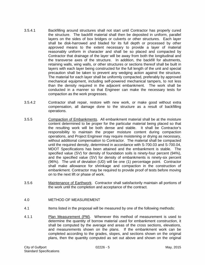
3.5.4.1 Backfilling around structures shall not start until Contractor has properly cured
the structure. The backfill material shall then be deposited in uniform, parallel layers on the sides of box bridges or culverts or other structures. Each layer shall be disk-harrowed and bladed for its full depth or processed by other approved means to the extent necessary to provide a layer of material reasonably uniform in character and shall be so placed and compacted by Contractor that drainage of the layer will be away from both the longitudinal and the transverse axes of the structure. In addition, the backfill for abutments, retaining walls, wing walls, or other structures or sections thereof shall be built in layers with each layer being constructed for the full length of the unit and special precaution shall be taken to prevent any wedging action against the structure. The material for each layer shall be uniformly compacted, preferably by approved mechanical equipment, including self-powered mechanical tampers, to not less than the density required in the adjacent embankment. The work shall be conducted in a manner so that Engineer can make the necessary tests for compaction as the work progresses.
3.5.4.2 Contractor shall repair, restore with new work, or make good without extra
compensation, all damage done to the structure as a result of backfilling operations.
3.5.5 Compaction of Embankments. All embankment material shall be at the moisture
content determined to be proper for the particular material being placed so that the resulting work will be both dense and stable. It shall be Contractor’s responsibility to maintain the proper moisture content during compaction operations, and Project Engineer may require moistening or drying as necessary, without additional compensation to Contractor. The material shall be compacted until the required density, determined in accordance with S-700.03 and S-700.04, MDOT Specifications has been attained and the embankment is stable. The specified value (SV) for density of foundation soils is ninety-four percent (94%), and the specified value (SV) for density of embankments is ninety-six percent (96%). The unit of deviation (UD) will be one (1) percentage point. Contractor shall make allowance for shrinkage and compaction in the construction of embankment. Contractor may be required to provide proof of tests before moving on to the next lift or phase of work.
3.5.6 Maintenance of Earthwork. Contractor shall satisfactorily maintain all portions of
the work until the completion and acceptance of the contract. 4.0 METHOD OF MEASUREMENT 4.1 Items listed in the proposal will be measured by one of the following methods: 4.1.1 Plan Measurement (PM). Whenever this method of measurement is used to
determine the quantity of borrow material used for embankment construction, it shall be computed by the average end areas of the cross sections, elevations, and measurements shown on the plans. If the embankment work can be completed according to the grades, slopes, and sections shown on the original plans, then the quantity computed as set out above and shown on the original
City of Gulfport 02226 - 5 May, 2015 Standard Specifications

plans will be the measurement for final payment. If during construction, however, the grades, slopes and/or sections are changed by Project Engineer for any reason, cross section templates reflecting the revised grades, slopes, and sections will be superimposed onto the original plan cross sections. The embankment volume delineated by these revised sections will then be computed by the method of average end areas, and the revised quantities so computed and reflecting any increased or decreased volume will be measured for final payment.
4.1.2 Loose Vehicle Measurement (LVM). Whenever this method of measurement is
specified, the excavation will be measured in the hauling vehicle at the point of deposit.
4.2 Excess excavation will be measured by the cubic yard, loose vehicle
measurement. 4.3 Stripping excavation will be measured by the cubic yard, plan measurement. 4.4 Borrow material will be measured by the cubic yard, plan measurement or loose
vehicular measurement as specified herein or on the plans. 5.0 PAYMENT 5.1 Payment will be made under Pay Item No.
02226-A Borrow Material, Type A
$_________________________________ per cubic yard (LVM)
02226-B Borrow Material, Type B $_________________________________ per cubic yard (PM)
02226-C Borrow Material, Type C $_________________________________ per cubic yard (LVM)
02226-D Stripping Excavation $_________________________________ per cubic yard (PM)
02226-E Excess Excavation $_________________________________ per cubic yard (LVM)
City of Gulfport 02226 - 6 May, 2015 Standard Specifications

02234 ..................................................................... GRANULAR BASE COURSE (LIMESTONE) 1.0 SCOPE OF WORK 1.1 This work shall consist of the furnishing of granular materials and the
construction of one (1) or more courses of base on a prepared foundation in reasonably close conformity with the lines, grades, and cross sections shown on the plans.
2.0 MATERIALS 2.1 The granular material shall be dense-graded crushed domestic limestone, plant
mixed to conform to Size No. 610 or 825B, MDOT Specifications. 3.0 CONSTRUCTION REQUIREMENTS 3.1 PREPARATION OF GRADE. The foundation on which granular material will be
laid shall be prepared by Contractor to the lines and grades established in the plans and compacted to ninety-five percent (95%) standard density.
3.2 MOISTURE CONTENT. All materials shall contain moisture content sufficient to
ensure that the design density requirements will be obtained when the materials are compacted.
3.3 SHAPING, COMPACTING, AND FINISHING 3.3.1 Contractor shall ensure that each course or layer of material is shaped to the
required section, watered or aerated as necessary to produce the required moisture content, and compacted. Throughout the compaction operation, the shape of the course or layer shall be maintained by blading and rolling so that the aggregates are uniformly distributed and firmly keyed.
3.3.2 Shaping and compaction shall be carried out by Contractor in such a manner that
will prevent lamination and shall continue until the entire depth and width of the course or layer has reached the required density. Surface compaction and finishing shall be performed so as to produce a smooth, closely knit surface that is free from lamination, cracks, ridges, or loose material. The finished surface shall conform (within allowable tolerances) to the required section at established lines and grades.
3.3.3 Prior to subsequent construction or final acceptance, all irregularities,
depressions, soft spots, and other deficiencies found by Project Engineer shall be corrected by Contractor to meet the requirements of these specifications, without additional compensation to Contractor.
3.3.4 After compaction and finishing, Contractor shall make at least one (1) complete
coverage with a steel wheel tandem roller. The resulting surface shall then be
City of Gulfport 02234 - 1 May, 2015 Standard Specifications

sprinkled as necessary to maintain the required moisture content and shall be thoroughly compacted and sealed with a pneumatic roller.
3.3.5 Contractor shall be responsible for constructing and maintaining a course which will remain firm and stable under construction equipment and other traffic to which the course will be subjected.
3.3.6 The specified density shall be ninety-five percent (95%) standard density. 3.3.7 Unless pavement is to follow immediately after preparation of base course, the
surface shall be primed in conformity with Section 408, MDOT Specifications. 4.0 METHOD OF MEASUREMENT 4.1 Accepted quantities of granular base course (limestone) will be measured by the
cubic yard, plan measure. 4.2 Accepted quantities of granular base course (limestone) for granular driveway
restoration will be measured by the cubic yard, 6” thickness, field measure. 5.0 PAYMENT 5.1 Payment will be made under Pay Item No.
02234-A Crushed Limestone Sub-base for Cuts in the Street R-O-W
$ per cubic yard (FM) 02234-B Limestone Granular Base Course for Driveways
$ per cubic yard (FM)
WARNING
AVOID BREATHING DUST FROM LIMESTONE
o This product contains crystalline silica. Prolonged and repeated breathing of crystalline silica dust can cause a progressive lung disease called silicosis.
o Some researchers have also reported that there is evidence that
prolonged and repeated breathing of crystalline silica dust might cause lung cancer.
o Either silicosis or lung cancer can result in permanent injury or death.
City of Gulfport 02234 - 2 May, 2015 Standard Specifications

o For detailed information, see the Material Safety Data Sheet before using or handling this product.
City of Gulfport 02234 - 3 May, 2015 Standard Specifications

02244 ......................................................................... LIME AND FLY-ASH TREATED COURSE 1.0 SCOPE OF WORK 1.1 This work shall consist of furnishing lime and fly-ash to construct one (1) or more
treated base courses of a mixture of soil, soil aggregate or aggregate, fly-ash, lime, and water in accordance with these specifications and in reasonably close conformity with the lines, grades, thicknesses, and typical cross sections as shown on the plans.
1.2 Unless otherwise provided, the Contractor may use either the travel plant or
central plant method. 1.3 SPECIFIED ELSEWHERE. Roadway Excavation and Embankment – 02226 2.0 MATERIALS 2.1 Aggregate, water, lime, and fly-ash shall be as required in Section 311.02 of the
MDOT Specifications, latest edition, or approved equivalent. 2.2 SOIL – LIME – FLY-ASH DESIGN 2.2.1 The actual application rate for lime and fly-ash will be established by a testing
laboratory secured by the Contractor and approved by Project Engineer from tests made prior to beginning treatment. The testing laboratory shall have previous successful experience in preparing a design report with this type of process and procedures. Contractor shall be responsible for taking samples, performing tests, acquiring materials for tests, and submitting a design to Engineer for approval prior to construction.
3.0 CONSTRUCTION REQUIREMENTS 3.1 The rough-graded road surface shall then be proof-rolled with a partially loaded
dump truck in the presence of the Project Engineer and the City Engineer or their designees. Any areas shown to be soft and yielding shall be undercut and the unsuitable material shall be replaced with stable material. The purpose of this is to detect and correct any areas of native material which will be unsuitable to incorporate into the lime/fly –ash base.
3.2 Contractor shall ensure that the character of the material in place on the roadway
conforms with the samples used to prepare the laboratory design of the lime/fly-ash base. If areas are found where the material appears to be substantially different, then a new design mix shall be prepared to apply to those areas, or else the existing material shall be removed and replaced by material which matches the tested material.
3.3 Requirements for constructing a lime, fly-ash soil stabilized base shall conform to
the requirements of Section 311.03 of the MDOT Specifications.
City of Gulfport 02244 - 1 May, 2015 Standard Specifications

3.4 Unconfined compressive strength of lime and fly-ash stabilized soils shall be 200
psi at seven (7) days. A CBR test must be run on the mix design in the laboratory to conform the data from the unconfined compressive strength tests. Relative densities must also be determined in the lab. The Owner will be responsible for determining the relative densities and having the field density testing accomplished.
3.5 The beginning of each day’s treated base course operation shall overlap the end
of the preceding recycling operation a minimum of fifty (50) feet unless otherwise directed by the Engineer. Any fillet of fine, pulverized material which forms adjacent to a vertical face shall be removed prior to spreading the treated base course mix, except that such fillet adjacent to the existing pavement that will be removed by overlapping during subsequent operations need not be removed. Vertical cuts in the area being treated shall NOT be left overnight. The operation shall be conducted in a manner that does not disturb the underlying subbase material that is not to be treated. Passes shall overlap at the longitudinal joint a minimum of four (4) inches.
3.6 MIXING. In addition to the requirements of Section 311.03.6 of the MDOT
Specifications, when commencing operations, the binder shall be applied to the pulverized in situ or select material at the initial design rate determined by the laboratory, based on samples obtained by Contractor prior to construction. The exact application rate of the binder and/or reagents will be determined and may be varied as required by existing conditions. An allowable tolerance of plus or minus 0.2 percent of the initial design rate or directed rate of application shall be maintained at all times.
3.6.1 The mixing operation shall be conducted in a manner that does not disturb the
underlying subbase material that is not to be treated. 3.6.2 Contractor shall blend the cementatious materials into the soil to the specified
depth, forming a pulverized homogeneous mixture for the full depth, but not less than ten (10) inches. Water shall be added concurrently with the blending operation to provide necessary moisture for the hydration of the binder and/or reagent and to maintain uniform optimum moisture content. If site conditions indicate a need to vary the application rate, contact Engineer at once for needed adjustments.
3.6.3 The Contractor will add water to the pulverized material to facilitate uniform
mixing with the binder and/or reagents. Water will be added concurrently with the binder and/or reagent, providing necessary moisture for the hydration of the binder and/or reagent and maintain uniform optimum moisture content.
3.7 SPREADING. Treated base course stabilization shall be at a rate sufficient to
provide continuous operation of the spreading machinery. If spreading operations result in being excessively behind or in excessive stopping of the spreading machinery, as determined by the Engineer, operations shall be suspended. Treatment may resume when the Contractor can synchronize the rate of the operations with the capacity of the spreading, compaction, and finishing machinery.
City of Gulfport 02244 - 2 May, 2015 Standard Specifications

3.8 SHAPING, COMPACTING, AND FINISHING. In addition to Section 308.03.9 of the MDOT Specifications, shaping, compacting, and finishing shall be in accordance with the following requirements:
3.8.1 After the treated base course material has been spread, traffic, including
Contractor’s equipment, shall not be allowed on the mixture until directed by the Engineer. However, if precipitation is imminent, compaction may proceed to seal the surface from additional moisture.
3.8.2 Compaction equipment and technique shall be at Contractor’s option. However,
If any type of cracking, movement, or other type of distress is observed while rolling, discontinue rolling and contact Engineer. After compaction is completed, NO traffic including Contractor’s equipment shall be permitted on the treated base until the material has cured.
3.8.3 The treated base course material shall be compacted to a minimum of ninety-five
percent (95%) of the density of a laboratory specimen compacted in accordance with ASTM D 698. The frequency of density testing for project acceptance will be a minimum of one (1) per 500 square yards. The Owner shall be responsible for having field density tests conducted and compared with the density of the approved laboratory mix design specimen.
3.8.4 At the option of the Engineer, the field compaction may be controlled by using a
uniform rolling pattern. If the uniform rolling pattern is used, the Contractor shall demonstrate that the proposed rolling pattern will achieve a minimum relative compaction of ninety-five percent (95%) of the density of a laboratory specimen compacted in accordance with ASTM D 698. The Engineer may require a re-demonstration of rolling capabilities if a change in the recycled material is observed, a change in rolling equipment is made, large temperature changes are encountered, and/or if the required densities are not being obtained with the rolling pattern being used.
3.8.5 Roller vibration shall not be started or stopped on newly compacted treated base
course material. Rolling shall be accomplished so that starting and stopping of roller vibration will be on accepted previously compacted recycled material or on existing un-recycled pavement.
3.8.6 Any type of rolling that results in cracking, movement, or other types of pavement
distress shall be discontinued until the problem is resolved. After the treated base course material has been compacted, traffic, including the Contractor’s equipment, shall not be permitted on the completed recycled material for at least one (1) hour, unless otherwise approved.
3.8.7 Before placing the prime coat or hot bituminous pavement overlay, the treated
base course material shall be allowed to cure until the free moisture content is reduced to one percent (1%) free moisture or less, by total weight of mix or until no surface movement is evident during the proof-rolling on the completed treated base course as approved by the Engineer. Free moisture is defined as moisture present which is not absorbed by the pulverized bituminous material blended into the existing underlying base to create a reconstructed base course. After the moisture content of the treated base course material has reached the acceptable
City of Gulfport 02244 - 3 May, 2015 Standard Specifications

level, the hot bituminous pavement overlay or prime coat, when required, shall be placed. The prime coat shall be applied to the surface at an approximate rate of 0.25 to 0.30 gallons per square yard and shall consist of a fifty percent (50%) dilution of an acceptable asphalt emulsion and water. The prime coat shall be installed when the Engineer determines that compaction and final grading have been achieved.
3.8.8 Any damage caused by the Contractor and any soft spots detected by the proof-
rolling on the completed recycled pavement shall be repaired by the Contractor, as directed, prior to placing any hot bituminous surfacing. Repairs shall be at the Contractor’s expense.
3.8.9 The completed and cured base shall be proof rolled with a one-half full single
axle or tandem axle dump truck in the presence of Project Engineer and the City Engineer or their designees. Any areas found to be yielding under the wheel load shall be undercut and repaired as directed by the City Engineer and then re-tested until satisfactory results are obtained.
3.9 OPERATIONS. The Contractor shall furnish a self-propelled mixer capable of
pulverizing in-place materials to a minimum depth of sixteen (16) inches, in one (1) pass. The machine will have a minimum rotor cutting width of eight (8) feet and shall have a rotor complete with necessary tooth cutters. The rotor cutting width selected for the project shall allow for longitudinal joint to be offset from the longitudinal joint of the layer placed above by approximately six (6) inches. In no case shall the longitudinal joint fall in the wheel path. The machine shall have standard automatic depth controls, and maintain a constant cutting depth. The machine shall also incorporate screening and/or crushing capabilities (breaker bar) to reduce or remove oversized particles prior to mixing with binder.
3.9.1 Provisions shall be made for continuous volume measurement of the treated
base course material, interlocked with the liquid metering device in order that the desired liquid content will be maintained. Positive means shall be provided for calibrating the volume measurement device and the liquid meter device. The Contractor shall be required to have a competent operator experienced in the use and operation of the equipment.
3.9.2 The reagents shall be blended through a self-propelled mixing and pulverizing
machine capable of mixing the lime, fly-ash, base, and the liquid to homogeneous mixture and placing the mixture in a fluffed spread for proper curing time. The method of depositing the mixed material in a fluffed spread shall be such that segregation does not occur.
3.9.3 A positive displacement pump, capable of accurately metering the required
quantity of rates as low as four (4) gal/min, shall be used to apply the liquid to the treated base course material. The pump shall be equipped with a positive interlock system which will permit addition of the liquid only when the treated base course mixture is present in the mixing chamber and will automatically shut off when the material is not in the mixing chamber or when the mixing machine stops.
City of Gulfport 02244 - 4 May, 2015 Standard Specifications
3.9.4 Each mixing machine shall be equipped with a meter capable of registering the rate of flow and total amount of the liquid introduced into the mixture through a computerized additive system.
3.10 COMPACTORS. The number and weight of rollers shall be sufficient to obtain
the required compaction while the mixture is in workable condition. 3.11 Grade tested base material to the required section, and compact the entire
thickness to not less than 95% of the optimum laboratory density per ASTM D 698. Provide density tests at the rate of one test per 500 square yards of completed work, or not less than one test for each day’s work.
3.11.1 Core samples shall be taken at random locations not less than 500 feet apart.
These cores shall be laboratory tested and shall have an unconfined compressive strength of not less than 90% of the design mix compressive strength, with due consideration of the amount of cure time of the specimens before testing.
3.11.2 Core holes and any other defects in the surface of the base shall be repaired with
asphalt mix or other approved material prior to placement of asphalt surface. 4.0 MEASUREMENT 4.1 Measurement for payment shall be by the square yard, plan measurement (PM)
at a specified depth which shall include preparation of application rate by the contractor’s engineer, and the furnishing of all material, mixing and completing of a lime and fly-ash treated course in accordance with these specifications.
5.0 PAYMENT Payment shall be made under Pay Item No. 02244-A Lime and Fly-Ash Treated Course (____” Thick) $_________________________________________per square yard (PM)
City of Gulfport 02244 - 5 May, 2015 Standard Specifications

02295 ....................................................................................... STORMWATER MANAGEMENT 1.0 SCOPE OF WORK 1.1 This work shall consist of supplying the necessary materials and labor and
constructing and maintaining, throughout the period of construction, stormwater management structures and devices, as shown on the plans or as directed by the Engineer.
1.2 The work shall also include implementing and adhering to the City approved
stormwater management plan, monitoring and inspecting stormwater management structures, and completing and submitting appropriate monitoring reports on a monthly basis. Monthly pay applications will not be processed unless accompanied by that month’s report.
1.3 All work and construction shall be in accordance with City of Gulfport
Ordinance No. 2419 “Erosion, Sediment, and Post-Construction Control”, regarding stormwater management.
1.4 A copy of the Stormwater Construction Notice of Intent (CNOI) or Small
Construction Notice of Intent (SCNOI), Stormwater Pollution Prevention Plan (SWPPP), and the inspection report forms are included elsewhere in the contract documents.
1.5 SPECIFIED ELSEWHERE. Clearing and Grubbing – 02111
Roadway Excavation and Embankment – 02226
Granular Base Course (Limestone) – 02234 Riprap – 02752 Plant Establishment – 02930 1.6 All erosion controls shall be in place prior to staring construction. 2.0 MATERIALS 2.1 Silt fence materials shall be in accordance with Section 234.02, MDOT
Specifications. 2.2 Straw Wattles shall consist of rice or wheat straw, shall be twelve (12) inches in
diameter (± 1 inch), shall be wrapped in a tubular plastic netting and shall be furnished in lengths of twenty (20) feet or greater.
2.3 Grass and sod shall be in accordance with Section 02931 of these specifications. 2.4 Gravel or limestone for construction entrances shall be in accordance with Section
02234 of these specifications. 2.5 Rock check dams shall be constructed of riprap meeting the requirements of
Section 02752.
City of Gulfport 02295 - 1 May, 2015 Standard Specifications

3.0 CONSTRUCTION REQUIREMENTS 3.1 Gravel or limestone construction entrances shall be constructed at the locations
and to the dimensions shown on the plans. 3.1.1 The construction entrance shall be maintained in a condition that will prevent the
tracking or flow of mud onto public rights-of-way. This may require periodic top dressing with additional gravel or limestone as conditions may demand. All materials spilled, dropped, washed, or tracked from vehicles onto roadway or into storm drains shall be removed immediately.
3.1.2 When the construction entrance is no longer necessary (the site has been paved),
the materials shall be removed from the site by the Contractor at his expense. 3.2 Silt fences shall be constructed at the locations shown on the plans or as directed
by the Project Engineer. 3.2.1 All posts shall be installed so that not more than three (3) feet of the post shall
protrude above the ground. Extra posts for bracing shall be installed as necessary by the Contractor to provide stability. The woven wire shall be securely fastened to the wood posts with staples. When metal posts are used, the wire shall be fastened to the post with wire or other approved means. The fabric shall be attached to the wire fence by wire or other approved means. The bottom edge of the fabric shall be buried six (6) inches below ground surface to prevent undermining. When splicing of the fabric is necessary, two (2) posts shall be installed approximately eighteen (18) inches apart, and each piece of fabric shall be fastened to both posts.
3.2.2 The fabric will be rejected if it has defects, rips, holes, flaws, deterioration, or
damage incurred during manufacture, transportation, storage, or installation. 3.2.3 Type II material may be installed without woven wire, provided that all of the
conditions stated in Paragraph 234.03.1 of the MDOT Specifications are met. 3.3 Straw Wattles shall be installed as shown on the plans or as directed by the Project
Engineer. They shall be placed on contour and staked with 18 inch or 24 inch wood stakes at four (4) foot on center. The ends of adjacent Straw Wattles shall be abutted to each other snugly.
3.4 Inlet protection shall utilize silt fencing and/or Straw Wattles to prevent sediment
from entering into the storm drainage system. 3.5 Silt basins shall be constructed to the dimensions and at the locations shown on
the plans or as directed by the Project Engineer. The silt basins shall be cleaned out as frequently as necessary to have at least fifty percent (50%) of the basin capacity available at all times. The silt basins shall be backfilled, compacted, and the areas shaped and dressed for seeding and mulching prior to completion of the project, unless otherwise directed by the Project Engineer. Grassing shall be done in accordance with the provisions contained in these specifications.
City of Gulfport 02295 - 2 May, 2015 Standard Specifications

3.6 Grass seed and sod shall be in accordance with Section 02930 of these
specifications. 3.7 Rock check dams shall be constructed to the general dimensions and in the
locations as shown on the plans. 3.8 MONITORING, MAINTENANCE, AND REMOVAL 3.8.1 The Contractor shall adhere to the City approved Stormwater Pollution Prevention
Plan, which is included in this section. This Plan requires the monitoring and reporting of on-site stormwater management devices.
3.8.2 Monitoring shall occur at least once a week and after any rainfall event of one-half
(½) inch or more. A maintenance report shall be made after each inspection, and these reports will be reproduced by the Contractor if requested by Project Engineer, City Engineer or other Regulatory Agency Representative.
3.8.3 The Contractor shall maintain all silt fences, erosion checks, rock check dams and
silt basins throughout the project. When silt has accumulated against or within stormwater management devices, it shall be removed. When silt fences become ineffective or torn, they shall be replaced immediately. Maintenance shall be performed immediately as necessary to prevent erosion.
3.8.4 When stormwater management devices are no longer needed (i.e., site stabilized,
project completed, and grass or vegetation has been established), they shall be removed and shall become the property of the Contractor for reuse or disposal. Disposal of all materials will be in accordance with all federal, state, and local laws and regulations. The area shall be neatly restored as close to its original state and given a pleasing appearance. All bare areas shall be seeded or sodded.
3.8.5 When rock check dams are no longer necessary, the riprap shall be placed within
on-site drainage features such as pipe outlets, at headwalls or other areas where its use may prevent erosion.
4.0 METHOD OF MEASUREMENT 4.1 Silt fences shall be measured by the linear foot for the length of fence that is
actually constructed, which shall be full compensation for its construction and maintenance and removal of silt accumulations throughout the project. There shall be no separate measurement or payment for the replacement of damaged or ineffective silt fence.
4.2 The contract price paid per linear foot of Straw Wattles shall include full
compensation for furnishing all labor, material, including wood stakes, tools, equipment, and incidentals for all work involved in furnishing and installing Straw Wattles, complete in place as directed by the Project Engineer.
4.3 Silt basins complete-in-place and accepted will be measured per each. 4.4 Gravel or limestone construction driveways shall be measured in accordance with
City of Gulfport 02295 - 3 May, 2015 Standard Specifications

Section 02234. 4.5 Rock Check Dams shall be constructed at the locations and to the dimensions
shown on the plans and shall be measured as a unit, per each. 5.0 PAYMENT 5.1 Payment shall include all materials, installation, construction, maintenance,
replacement, if necessary, and removal of silt throughout the project and will be full compensation for completing the work.
5.2 Payment shall be made in accordance with Pay Item No. 02295-A Silt Fence $ per linear foot
02295-B Straw Wattles $ per each 02295-C Temporary Silt Basins $ per each 02295-D Rock Check Dams $ per each
City of Gulfport 02295 - 4 May, 2015 Standard Specifications

02512 ...................................................................................... HOT BITUMINOUS PAVEMENTS
1.0 SCOPE OF WORK 1.1 This work shall consist of constructing one or more courses of bituminous
pavement on a prepared foundation in accordance with the requirements of these specifications and in reasonably close conformity with the lines, grades, thicknesses, and typical sections shown on the plans.
1.2 The bituminous pavement shall be composed of mineral aggregates, filler or
other material, if required and bituminous material, mixed in a central plant and placed hot.
1.3 The work shall be in general accordance with Sections 401 and 403, Mississippi
Standard Specifications for Road and Bridge Construction, latest edition. 2.0 MATERIALS 2.1 Materials and their use shall meet the applicable requirements of Section 401
and all other referenced sections of the Mississippi Standard Specifications for Road and Bridge Construction, latest edition.
3.0 CONSTRUCTION REQUIREMENTS 3.1 The construction requirements shall be as prescribed in Sections 401 and 403,
Mississippi Standard Specifications for Road and Bridge Construction, latest edition, and/or all current Special Provisions.
3.2 Surface course thickness in excess of two (2) inches shall be constructed in two
(2) lifts. The minimum overall thickness for two-lift surfaces shall not be less than 3 inches. Acceptable thickness of the specified lift shall be in accordance with Section 401.02.04 of the Mississippi Standard Specifications for Road and Bridge Construction, latest edition, by mixture.
3.3 The Contractor shall perform a subgrade proof roll test on all city streets prior to
pavement or base application in the presence of the City Engineer or his duly authorized representative. This test must be coordinated through the City Engineering Department at least 48 to 72 hours prior to the proof roll inspection.
3.3.1 Proof rolling shall be performed by the utilization of a tandem-axle twelve (12)-
cubic yard ¾-loaded dump truck or equivalent load, as approved by the City Engineer.
3.3.2 Asphalt shall be rolled and compacted per MDOT Standards. When paving on
new surfaces a prime coat shall be applied at a rate of 0.25 gal/ per square yard.
City of Gulfport 02512 - 1 May, 2015 Standard Specifications

4.0 METHOD OF MEASUREMENT 4.1 Accepted quantities of hot bituminous pavement, MDOT ST, 12.5 mm mix, of a
specified thickness, will be measured by the square yard, plan measure. 4.2 Accepted quantities of hot bituminous pavement, MDOT ST, 19 mm mix, of a
specified thickness, will be measured by the square yard, plan measure. 5.0 PAYMENT 5.1 Payment will be made under Pay Item No.
02512-A Hot Bituminous Pavement (MDOT ST, 12.5 mm mix)(___” Thick)
$ per square yard
02512-B Hot Bituminous Pavement (MDOT ST, 19 mm mix)(___” Thick)
$ per square yard
City of Gulfport 02512 - 2 May, 2015 Standard Specifications

02521 ................................................................ CURB AND COMBINATION CURB & GUTTER 1.0 SCOPE OF WORK 1.1 This work shall consist of constructing curb, gutter, and combination curb and gutter in
accordance with these specifications and in reasonably close conformity with the lines, grades, dimensions and cross-sections shown on the plans.
1.2 All curb and gutter shall be constructed to meet current ADA Standards. 2.0 MATERIALS 2.1 Concrete — Class B, MDOT Specifications. 2.2 Reinforcement — Deformed, Grade 40 or 60 Billet Steel, ASTM A-615. 2.3 Pre-Molded Joint Filler — Bituminous, ½ inch thick, per AASHTO M-213. 2.4 Curing Compound — ASTM C-309. 3.0 CONSTRUCTION REQUIREMENTS 3.1 Excavation and Grade Preparation 3.1.1 Excavation and grade preparation for curb, gutter, and combination curb and gutter shall
be included in the cost of the curbing. Material below curb and gutter shall be compacted to 95% Standard Proctor Density.
3.2 Forms 3.2.1 Forms, except for divider plates and templates, may be wood or metal. All forms shall be
full depth, straight, and free of warp and shall be securely staked, braced, and sufficiently tight to prevent leakage of mortar. All forms shall be cleaned thoroughly and oiled before placing concrete against them.
3.2.2 Lumber for wood forms shall be sound, free of bulges, loose knots, and warps, and of
uniform width. All lumber shall be dressed and at least two inches (commercial) thick, except Project Engineer may permit the use of flexible material on short radii.
3.2.3 Metal forms shall be approved sections and shall have a flat surface on top. They shall
present a smooth surface and be of sufficient strength when braced to withstand the weight of the concrete without bulging or displacement. Special care shall be exercised by Contractor to keep metal forms free from rust, grease, or other foreign matter which would discolor the concrete.
3.2.4 Metal templates or dividing plates shall be of sufficient thickness and of such design as to
hold the forms rigidly in place and to produce a smooth vertical joint after the plates are removed. They shall be of the full dimensions shown on the plans.
City of Gulfport 02521 - 1 May, 2015 Standard Specifications

3.3 Placing Concrete 3.3.1 Unless otherwise specified, concrete used for curb, gutter, and combination curb and
gutter shall be Class B, proportioned, mixed and placed in accordance with the provisions of S-601, MDOT Specifications.
3.3.2 Contractor shall place the concrete on a moist grade, consolidating it by vibration or other
acceptable methods, and shall place weep holes through the curbs, where indicated on the plans.
3.4 Extruded Construction 3.4.1 Concrete curb and curb and gutter may be constructed by the use of a curb forming
machine. Its continued use shall be contingent upon it producing curb with the specified section, line and grade. If these conditions cannot be met, construction shall be by conventional methods.
3.5 Sections and Joints 3.5.1 Concrete curb, gutter or combination curb and gutter, shall be constructed in uniform
sections of the length specified on the plans. These lengths may be reduced where necessary for closure, but no section less than six (6) feet will be permitted. Contractor shall accurately set the templates before placing the concrete and allow them to remain in place wherever possible until the concrete has set sufficiently to hold its shape, but shall remove them while the forms are still in place.
3.5.2 Expansion joints shall be formed of pre-molded joint filler of the specified thickness, and
shall be placed by Contractor in line with the expansion joints in the adjoining pavement or structure and at other locations designated on the plans. All joint fillers shall be cut to full cross section and shall extend for full depth, width and length. All expansion joint material protruding after the concrete is finished shall be trimmed as directed. Immediately after removal of forms, Contractor shall carefully expose the outer edges of filled joints.
3.6 Finishing 3.6.1 The concrete shall be finished smooth and even by a wood or other approved float. Forms
on the face of curbs shall be removed as soon as the concrete will hold its shape, and the surface shall be finished with a wood float to a smooth even texture. Plastering will not be permitted. Strike-off templates of the form and shape of the gutter shall be used to shape the top surface of gutters. Before final finishing, Contractor shall check the surface of the gutters with a ten (10) foot straight-edge and all irregularities of more than 1/8 inch in ten (10) feet shall be corrected.
3.6.2 Edges on the faces of curbs shall be rounded with finishing tools having the radii shown on
the plans. Edges where templates have been removed or expansion joint material has been placed shall be finished with an edging tool have a radius of 1/4-inch. All exposed surfaces against which some rigid type of construction is to be made shall be left smooth and uniform so as to permit free movement of the curb, gutter, or combination curb and gutter.
City of Gulfport 02521 - 2 May, 2015 Standard Specifications

3.6.3 Contractor shall remove all tool marks with a wetted brush or wood float. The finished surface shall be a uniform color free from discolorations.
3.6.4 Where water valves are located either in the pavement or behind the curb, the curb face
shall be stamped “WV” at the point where the alignment of the curb is perpendicular to the water valve.
3.7 Protection and Curing 3.7.1 After finishing operations have been completed and immediately after free water has
evaporated, the surface and any exposed edges shall be uniformly coated by Contractor with the membrane-curing compound. It can be applied by a pressure sprayer, with a maximum coverage of 200 ft2/gal. Two (2) applications at 90°offset may be required on windy days.
3.7.2 Contractor shall have materials available at all times for the protection of unhardened
concrete against rain. During the curing period, all traffic, both pedestrian and vehicular, shall be kept off the concrete. Vehicular traffic shall be kept off for such additional time as Engineer may direct. Contractor shall protect the work from damage until final acceptance. All sections which are damaged before final acceptance shall be removed and reconstructed by Contractor without additional compensation.
3.8 Backfilling and Clean Up 3.8.1 After the concrete has set sufficiently, Contractor shall fill the areas on the sides of the
curb, gutter and combination curb and gutter to the required elevation with the specified materials and compacted as specified.
3.8.2 All surplus material shall be disposed of by Contractor as directed, and the entire area
shall be left in a neat and satisfactory condition. 4.0 METHOD OF MEASUREMENT 4.1 Complete, in place, concrete curb, gutter and mountable curb and gutter will be measured
by the linear foot along the face of the curb or flow line of the gutter. A deduction will be made for driveway openings.
5.0 PAYMENT 5.1 Payment shall be made in accordance with Pay Item No. 02521-A Mountable Curb and Gutter $ per linear foot 02521-B Free Standing Curb $ per linear foot
City of Gulfport 02521 - 3 May, 2015 Standard Specifications

02522 ............................................................... SIDEWALKS, ADA RAMPS, AND DRIVEWAYS 1.0 SCOPE OF WORK
1.1 This work shall consist of constructing portland cement concrete sidewalk, ADA
ramps or driveway on a prepared subgrade in accordance with the plans and specifications. Lines and grades shall be as shown on the plans. “Subgrade” in this section shall mean the prepared foundation on which the sidewalk or driveway is constructed.
1.2 All pedestrian traffic areas including sidewalks and ramps shall conform to the
requirements of the Americans with Disabilities Act (ADA). 1.3 Specified Elsewhere. 2.0 MATERIALS 2.1 Concrete — Class B, MDOT Specifications. Water will not be added to truck
mixed concrete on site unless approved by City Engineer Department. 2.1.1 Concrete mixed by hand or on site concrete mixer shall be mixed at a minimum
of 3,500 psi. 2.2 Reinforcement. Driveways — 6 x 6 No. 6 WWF or Fiber additive as approved by
Engineer. Sidewalks and Ramps — if required, it will be specified on the plans. 2.3 Pre-Molded Expansion Joint Filler — Bituminous, ½ inch thick, per AASHTO M-
213. 2.4 Curing Compound — ASTM C-309 2.5 Detectable / Tactile Warning Surfaces – Both cast-in-place and surface applied
detectable / tactile warning surface tile shall be produced of a vitrified polymer composite (VPC) such as Armor-Tile as manufactured by Engineered Plastics, Inc. (800-682-2525) or approved equal. If not indicated otherwise on the plans, the color of the product shall be yellow conforming to Federal Color No. 33538.
2.5.1 For surface applied detectable / tactile warning surface tiles, the following or an
approved equivalent shall be used:
a) Fasteners: Color matched, corrosion resistant, flat head drive anchor: ¼” diameter x 1 ½” long as supplied by Engineered Plastics, Inc. or approved equal.
b) Adhesive: Armor-Bond as supplied by Engineered Plastics, Inc. or
approved equal.
c) Sealant: Armor-Seal as supplied by Engineered Plastics, Inc. or approved equal.
City of Gulfport 02522 - 1 May, 2015 Standard Specifications

3.0 CONSTRUCTION REQUIREMENTS 3.1 Excavation and In-Grade Preparation 3.1.1 Excavation shall be made to the required depth and to a width that will permit the
installation and bracing of forms. The foundation shall be shaped and compacted at the proper moisture content to a firm, even surface conforming to the lines, grades and sections shown on the plans. All soft, spongy, or other unsuitable materials encountered shall be removed and replaced with acceptable material. The foundation shall be shaped and compacted to 90% Standard Proctor at the proper moisture in areas with no traffic load and 95% in areas where traffic passes over.
3.2 Setting Forms. Forms shall be set to the required line and grade and rigidly held
in place by stakes or braces. Ends of adjoining form sections shall be flush. Forms and division plates shall be cleaned and oiled before placing concrete against them.
3.3 Placing Concrete 3.3.1 A template resting upon the side forms and having its lower edge at the elevation
of the subgrade shall be drawn along the forms to shape and grade the subgrade before concrete is deposited. The subgrade shall be moist and free of debris and foreign material before concrete is deposited upon it. The concrete mixture shall be placed on the prepared subgrade to the depth required to complete the sidewalk or driveway in one course. It shall then be vibrated and/or tamped and struck off with an approved straight-edge resting upon the side forms and drawn forward with a sawing motion. The surface shall be given a float finish.
3.3.2 The edges of the sidewalk shall be rounded with an edging tool having a radius
of ½ inch. Expansion joints shall be edged with an edger having a radius of ¼ inch.
3.3.3 The edges of driveways at expansion joints shall be edged with an edger having
a radius of ½ inch. 3.4 Joints 3.4.1 Expansion joints shall be of the dimensions specified and shall be filled with the
type of premolded expansion joint filler specified. Sidewalks shall be divided into sections by dummy joints formed by a jointing tool or other acceptable means. These dummy joints shall extend into the concrete for at least one-inch and shall be approximately 1/8 inch wide. Joints shall match as nearly as possible adjacent joints in curb or pavements. Dummy joints may be sawed in lieu of forming with a joint tool.
3.4.2 Construction joints shall be formed around all appurtenances such as manholes,
utility poles, etc., extending into and through the sidewalk. Premolded expansion joint filler ¼-inch thick shall be installed in these joints. Expansion joint filler of the thickness indicated shall be installed between concrete sidewalks and fixed
City of Gulfport 02522 - 2 May, 2015 Standard Specifications
structure, such as a building or bridge. This expansion joint material shall extend for the full length of the walk.
3.5 Protection and Curing 3.5.1 After finishing and texturing operations have been completed and immediately
after free water has evaporated, the surface of the slab and any exposed edges shall be uniformly coated with the membrane-curing compound. It can be applied by a pressure sprayer, with a maximum coverage of 200 ft2/gal. Two applications at 90° offset may be required on windy days.
3.5.2 Contractor shall have materials available at all times for the protection of
unhardened concrete against rain. During the curing period, all traffic, both pedestrian and vehicular, shall be kept off the concrete. Vehicular traffic shall be kept off for such additional time as Engineer may direct. Contractor shall protect the work from damage until final acceptance. All sections which are damaged before final acceptance shall be removed and reconstructed by Contractor without additional compensation.
3.6 Detectable / Tactile Warning Surfaces. Detectable / Tactile Warning surface tiles
shall be either cast-in-place for new construction or surface applied to existing improvements. Installation will not be allowed on asphalt surfaces.
3.6.1 Cast-In-Place Installation 3.6.1.1 The specifications of the structural embedment flange system and related
materials shall be in strict accordance with the contract documents and the guildelines set by their manufacturers.
3.6.1.2 The physical characteristics of the concrete shall be consistent with the contract
specifications while maintaining a slump range of 4 – 7 to permit solid placement of the Cast-In-Place Tile system. An overly wet mix will cause the tile to float. Under these conditions, suitable weights such as 2 concrete blocks or sandbags (25 lb) shall be placed on each tile.
3.6.1.3 The concrete pouring and finishing operations require typical mason’s tools,
however, a four (4) inch long level with electronic slope readout, 25 lb. Weights, and a large non-marring rubber mallet are specific to the installation of the Cast-In-Place Tile system. A vibrating mechanism such as that manufactured by Vibco can be employed, if desired. The vibrating unit should be fixed to a soft base such as wood, at least one (1) foot square.
3.6.1.4 The factory-installed plastic sheeting shall remain in place during the entire
installation process to prevent the splashing of concrete onto the finished surface of the tile.
3.6.1.5 The concrete shall be poured and finished true and smooth to the required
dimensions and slope prior to the tile placement. Immediately after finishing concrete, a level should be used to check that the required slope is achieved. The tile shall be placed true and square to the curb edge in accordance with the drawings. The Cast-In-Place tiles shall be tamped (or vibrated) into the fresh concrete to ensure that the field level of the tile is flush to the adjacent concrete
City of Gulfport 02522 - 3 May, 2015 Standard Specifications

surface. The embedment process shall not be accomplished by stepping on the tile as this may cause uneven setting which can result in air voids under the tile surface. The contract drawings indicate that the tile field level (base of truncated dome) is flush to adjacent surfaces to permit proper water drainage and eliminate tripping hazards between adjacent finishes.
3.6.1.6 Immediately after placement, the tile elevation is to be checked to adjacent
concrete. The elevations and slope should be set consistent with contract drawings to permit water drainage to curb as the design dictates. Ensure that the field surface of the tile is flush with the surrounding concrete and back of curb so that no ponding is possible on the tile at the back side of curb.
3.6.1.7 While concrete is workable, a 3/8” radius edging tool shall be used to create a
finished edge of concrete, then a steel trowel shall be used to finish the concrete around the tile’s perimeter, flush to the field level of the tile.
3.6.1.8 Following tile placement, review installation tolerances to contract drawings and
adjust tile before the concrete sets. Two (2) suitable weights of 25 lbs. each may be required to be placed on each tile as necessary to ensure solid contact of the underside of tile to concrete.
3.6.1.9 Following the concrete curing stage, protective plastic wrap is to be removed
from the tile surface by curing the plastic with a sharp knife, tight to the concrete/tile interface. If concrete bled under the plastic, a soft brass wire brush will clean the residue without damage to the tile surface.
3.6.1.10 Individual tiles can be bolted together using ¼ inch or equivalent hardware. This
can help to ensure that adjacent tiles are flush to each other during the installation process. Tape or caulking can be placed on the underside of the bolted butt joint to ensure that concrete does not rise up between the tiles during installation. Any protective plastic wrap which was peeled back to facilitate bolting or cutting, should be replaced and taped to ensure that the tile surface remains free of concrete during the installation process.
3.7 Backfilling and Cleaning Up 3.7.1 When the concrete has set sufficiently, all forms, bracing, etc., shall be removed
and the sides of the walk or driveway shall be backfilled and compacted to the required elevation with suitable material. All surplus material shall be disposed of as directed, and the completed work and the site shall be left in a neat and presentable condition.
3.7.1.1 Set the tile true and square to the curb ramp area as detailed in the design
drawings, so that its location can be marked on the concrete surface. 3.7.1.2 The surface to receive the tile shall be mechanically cleaned with a diamond cup
grinder or shot blaster to remove any dirt or foreign material. This cleaning and roughening of the concrete surface should include at least four (4) inches around the perimeter of the area to receive the tile, and also along the cross pattern established by the corresponding areas on the backside of the tile. Those same areas should then be cleaned with a clean rag soaked in Acetone.
City of Gulfport 02522 - 4 May, 2015 Standard Specifications

3.7.1.3 Immediately prior to installing the tile, the concrete surfaces shall be inspected to
ensure that they are clean, dry, free of voids, curing compounds, projections, loose material, dust, oil, grease, sealers and determined to be structurally sound and cured for a minimum of thirty (30) days.
3.7.1.4 Using Acetone, wipe the backside of the tile around the perimeter and along the
internal cross pattern, to remove any dirt or dust particles from the area to receive the adhesive.
3.7.1.5 Apply adhesive to the backside of the tile, following the perimeter and internal
cross pattern established by the tile manufacturer. Sufficient adhesive must be placed on the prescribed areas to have full coverage across the two (2) inch width of the adhesive locator and shall be applied to within ¼” continuously around the perimeter edge of the tile. The entire tube of adhesive shall be applied to the back of each tile, sizes 24” x 36” and greater.
3.7.1.6 Set the tile true and square to the curb ramp area as detailed in the design
drawings. 3.7.1.7 Working from the center of the tile outwards, proceed to drill and install all
fasteners in the tile’s molded recesses. 3.7.1.8 Standing with both feet, applying pressure around the molded recess provided in
the tile, drill a hole true and straight to a depth of 3 ½” using a ¼” masonry drill bit. Drill through the tile without hammer option (on the drill) until the tile has been successfully penetrated, then with the hammer option (on the drill) to drill into the concrete.
3.7.1.9 Immediately after drilling each hole, before moving on to the next, and while still
applying foot pressure, mechanically fasten tiles to the concrete substrate using a leather bound or hard plastic mallet to set the fasteners. Ensure the fastener has been placed to full depth in the dome, straight, and flush to the top of dome.
3.7.1.10 Following the installation of the fasteners, the concrete dust should be
vacuumed, brushed or blown away from the tile’s surface and adjacent concrete. Using Acetone on a rag, wipe the concrete around the tile’s perimeter to ensure a clean, dry surface to receive perimeter sealant.
3.7.1.11 Perimeter caulking sealant shall be applied following the sealant manufacturer’s
recommendations. Tape all perimeter edges of the tile back 1/16” from the tile’s perimeter edge and tape the adjacent concrete back ½” from the tile’s perimeter edge to maintain a straight and even caulking line. Apply sealant around the perimeter using care to work sealant into any void between the tile and concrete interface. Tool the perimeter caulking with a rounded plastic applicator or spatula to create a cove profile between the tile and adjacent concrete. Remove tape immediately after tooling perimeter caulking sealant.
3.7.1.12 Do not allow foot traffic on installed tiles until the perimeter caulking sealant has
cured sufficiently to avoid tracking. Adhesive or caulking on the surface of the tile can be removed with Acetone.
City of Gulfport 02522 - 5 May, 2015 Standard Specifications

3.7.1.13 If installing adjacent tiles, note the orientation of each tile. Careful attention will
reveal that one of the long edges of the tile is different than the other in regard to the tiny dotted texture. You may also note a larger perimeter margin before the tiny dotted texture pattern begins. Consistent orientation of each Armor-tile is required in order that the truncated domes on adjacent tiles line up with each other.
3.7.1.14 In order to maintain proper spacing between truncated domes on adjacent tiles,
the tapered edge should be trimmed off using a continuous rim diamond blade in a circular saw or mini-grinder. The use of a straightedge to guide the cut is required. All cuts should be made prior to installation of the tiles. If installing adjacent tiles, care should be taken to leave a 1/8 inch gap between each tile to allow for expansion and contraction.
4.0 METHOD OF MEASUREMENT 4.1 Complete and accepted concrete sidewalks, ADA ramps and driveways will be
measured for payment by the square yard. Ramps shall be considered as sidewalks for payment.
4.2 Detectable / Tactile Warning Surface Tiles shall be measured by the square foot
and shall be paid for according to the installation method. 5.0 PAYMENT 5.1 Payment will be made in accordance with Pay Item No. 02522-A Concrete Sidewalk $ per square yard 02522-B Concrete Driveway $ per square yard 02522-C Detectable / Tactile Warning Surface Tiles (Cast-In-Place) $ per square foot 02522-D Detectable / Tactile Warning Surface Tiles (Surface Applied) $ per square foot
City of Gulfport 02522 - 6 May, 2015 Standard Specifications

02580 . . . . . . . . . . . . . . . . . . . . . . . . . . . . . . . . . . . . . . . . . . . . . . . . PAINTED TRAFFIC MARKINGS 1.0 SCOPE OF WORK 1.1 This work shall consist of furnishing materials and applying reflectorized paint traffic
markings in reasonably close conformity with these specifications and the details shown on the plans. This work shall fully conform to Section 625 “Painted Traffic Markings” of the Mississippi Standard Specifications for Road and Bridge Construction, latest edition.
2.0 MATERIALS 2.1 Materials shall be as specified in Sections 710, 720.01 and all other referenced sections of
the Mississippi Standard Specifications for Road and Bridge Construction, latest edition. 3.0 CONSTRUCTION REQUIREMENTS 3.1 Construction requirements will be in accordance with Sections 619 and 625 of
the Mississippi Standard Specifications for Road and Bridge Construction, latest edition. 4.0 MEASUREMENT 4.1 Painted Traffic Markings, in accordance with the plans and specifications, shall be
measured as a lump sum for the entire project. 5.0 PAYMENT 5.1 Payment will be in accordance with the stipulations of Section 625.05 and will be made
under the following pay items: 02580-A Painted Traffic Markings $ per lump sum
City of Gulfport 02580 - 1 May, 2015 Standard Specifications

02581 . . . . . . . . . . . . . . . . . . . . . . . . . . . . . . . . . . . . . . . .THERMOPLASTIC TRAFFIC MARKINGS 1.0 SCOPE OF WORK 1.1 This work shall consist of furnishing materials and applying reflectorized paint traffic
markings in reasonably close conformity with these specifications and the details shown on the plans. This work shall fully conform to Section 626 “Painted Traffic Markings” of the Mississippi Standard Specifications for Road and Bridge Construction, latest edition.
2.0 MATERIALS 2.1 Materials shall be as specified in Sections 720.01 and all other referenced sections of
the Mississippi Standard Specifications for Road and Bridge Construction, latest edition. 3.0 CONSTRUCTION REQUIREMENTS 3.1 Construction requirements will be in accordance with Section 626.03 of the Mississippi
Standard Specifications for Road and Bridge Construction, latest edition. 4.0 MEASUREMENT 4.1 Painted Traffic Markings, in accordance with the plans and specifications, shall be
measured as a lump sum for the entire project. 5.0 PAYMENT 5.1 Payment will be in accordance with Section 626.05 and will be made under the following
pay items: 02581-A Painted Traffic Markings $ per lump sum
City of Gulfport 02581 - 1 May, 2015 Standard Specifications

02585 . . . . . . . . . . . . . . . . . . . . . . . . . . . . . . . . . . . . . . . . . . . REFLECTORIZED TRAFFIC SIGNS 1.0 SCOPE OF WORK 1.1 This work shall consist of furnishing and installing delineators, reflectorized traffic signs
and markers, and reflectorized warning and railroad crossing signs, together with accessories and posts of the designated materials, sizes, shapes, weights, and designs, in reasonably close conformity with the requirements shown on the plans and set out in these specifications.
1.2 In general, the work and materials shall meet the requirements of the “Manual on Uniform
Traffic Control Devices for Streets and Highways”, or latest revision thereof except as modified by these specifications or as shown on the plans.
1.3 Sign fabrication shall be in a properly equipped plant which shall show evidence of
successful experience in fabrication and erection of quality reflectorized highway warning signs.
2.0 MATERIALS 2.1 All materials or equipment shall be of new stock and shall be the product of a reputable
manufacturer. Completed equipment and materials shall be guaranteed to be free from defects in materials and workmanship for a reasonable period of time after erection.
2.2 All materials shall conform to the material requirements of 630.02, MDOT Specifications,
latest edition. 3.0 CONSTRUCTION REQUIREMENTS 3.1 The construction requirements shall be as prescribed in 630.03 through 603.05, MDOT
Specifications, latest edition. 4.0 METHOD OF MEASUREMENT 4.1 Reflectorized signs of the size, color and markings as prescribed in the “Manual on
Uniform Traffic Control Devices for Streets and Highways”, or revision thereof, delineators and hazard markers will be paid for by the unit installed including posts, parts, fastenings, fittings, labor, tools and incidentals necessary to complete the work.
4.2 Reflectorized cross buck warning signs and Advanced Railroad Warning signs of the size,
color and markings as prescribed in the “Manual on Uniform Traffic Control Devices for Streets and Highways,” or revision thereof, will be paid for by the unit installed, including posts, parts, fastenings, fittings, labor, tools, and incidentals necessary to complete the work.
4.3 Concrete, if required for post stabilization, will not be measured and paid for separately,
but shall be included in the contract unit price bid per sign.
City of Gulfport 02585 - 1 May, 2015 Standard Specifications

4.4 Street name signs where required shall not be separately measured, but shall be included in the cost of the sign post that is to be mounted.
5.0 PAYMENT 5.1 Payment will be made under Pay Item No. 02585-A Reflectorized Traffic Signs $ per each
City of Gulfport 02585 - 2 May, 2015 Standard Specifications

02660 . . . . . . . . . . . . . . . . . . . . . . . . . . . . . . . . . . . . . . . . . . . . . . . . . . . . WATER PIPE & FITTINGS 1.0 SCOPE OF WORK 1.01 This work shall consist of all labor, materials, equipment, tools and services
required to furnish and install water mains, fittings, thrust blocks and related appurtenances at sites and locations as designated in these specifications and in reasonably close conformity with the lines and grades specified in the Drawings.
2.0 MATERIALS 2.1 Water Pipe (4" diameter and larger) shall be either of the following materials, at
Project Engineer’s option: 2.1.1 Polyvinyl Chloride (PVC) Pipe conforming to AWWA C-900, Class 150, SDR-18.
Pipe shall be made to cast iron O.D.'s. Each length of pipe shall be stamped with approval of National Sanitation Foundation and Underwriters Laboratories, Inc. for transporting potable water. Pipe couplings or joints shall be an integral part of the pipe barrel, consisting of an expanded bell with a groove to retain a rubber sealing ring conforming to the requirements of AWWA C-111. Gaskets shall be factory bonded into the groove. Pipe shall be in standard 20 foot lengths. Remaining random lengths shall not be less than 10 feet long.
2.1.2 Molecularly Oriented Polyvinyl Chloride (PVCO) pipe conforming to ASTM
Standards F1483, D1784, D2241, D3139, and D2774 and also designed using the same criteria as AWWA C900 for Class 150 pipe. Pipe shall be made to cast iron O.D.'s, and each length shall be stamped with the approval of the National Sanitation Foundation and Underwriters Laboratories, Inc., for transporting potable water. Pipe couplings shall be an integral part of the pipe barrel, consisting of an expanded bell with a factory-installed retained rubber sealing ring designed to avoid rolling of the ring during pipe joint assembly.
2.1.3 Ductile Iron Pipe conforming to ANSI/AWWA C151/A21.51 PC 350 Ductile Iron.
Pipe interior shall be cement mortar lined per ANSI/AWWA C104/A21.4. Rubber gasket joints per ANSI/AWWA C111/A21-11.
2.2 Fittings for pipes 4 inches in size or greater may meet any one of the following
specifications, at Project Engineer's option: 2.2.1 Cast Iron conforming with ANSI A-21.10 (AWWA C-110), 250 p.s.i rated. 2.2.2 Ductile Iron conforming with ANSI A-21.10 (AWWA C-110), 350 p.s.i. rated. 2.2.3 Compact Ductile Iron Fittings conforming with ANSI A-21.53 (AWWA C-153), 350
p.s.i. rated.
All fittings shall be cement mortar lined per ANSI A21.4 (AWWA C-104). All fittings shall be of the mechanical joint type.
City of Gulfport 02660 - 1 May, 2015 Standard Specifications

2.3 Mechanical Joint Retainer Glands shall be used for all connections of pipe to fittings and shall be made with a suitable restrained joint system, meeting any one of the following specifications:
2.3.1 For Ductile or PVC Pipe, a suitable ductile iron retainer gland, designed and
recommended by the gland manufacturer, for the type of pipe used. Gland shall be manufactured entirely of 60-42-10 ductile iron conforming to ASTM A536-80. Glands shall attach to the pipe barrel through a plurality of individually activated gripping surfaces (wedges). EBAA Iron "Megalug" series or equal.
2.3.2 For PVC Pipe, a heavy ductile iron or fused epoxy coated structural steel (ASTM
A36) clamp which employs serrations on its inside surface to firmly grip the outside of the PVC pipe barrel. Clamp shall be specifically designed and recommended for use with the size and thickness class of pipe used. All hardware shall be ductile iron. Uni-flange Series 1300 or approved equal.
2.3.3 For Ductile Pipe only, a ductile iron mechanical joint retainer gland employing
cupped-end threaded set screws which conform with the pipe manufacturer's guidelines as to number of set screws and torque to be applied to properly restrain the joint to a rating of not less than 250 p.s.i.
2.4 Pipe Joint Restraint (applicable only for pipe joints within specified distances from
fittings--see schedule in Drawings): Use two glands similar in design and materials to the joint retainer glands previously specified, one immediately behind the joint bell and one on the pipe spigot, connected by two or more ductile iron rods spanning across the pipe joint. For ductile pipe, it is also permissible to use mechanical joint pipe with restrained retainer gland, or special "lock-ring" pipe joints.
2.5 Detectable underground utility marker tape for burial with PVC pipe shall be a
minimum of 5 mils thick and 3 inches in width. Minimum tensile strength shall be 35 pounds and tape shall elongate not less than 80 percent before breaking. Tape shall be permanently imprinted with an appropriate legend to identify the contents of the pipe (e.g. "Water Main Below").
2.6 Electronic Ball Markers shall be provided in a standard frequency and color coded
(blue) to APWA standards for water systems. The markers shall be readable with proper instrumentation to a bury depth of five (5) feet. The markers shall be a four (4) inch diameter sphere, weigh 0.77 lb., have a high-density, watertight polyethylene shell. Electronic ball markers shall be model no. 1423-XR/iD as manufactured by 3M or an approved equivalent.
2.7 Concrete shall conform to requirements for Class B concrete, MDOT Standard
Specifications. 2.8 Reinforcement shall be grade 40 or grade 60 billet steel conforming to ASTM
A-615. 2.9 Water Sampling Stations shall be furnished in a heavy-duty non-corroding
lockable box with an anchor post; shall have a water evacuation system for freeze control; shall have a separate tap for flow control and shall be model no. EH101 as
City of Gulfport 02660 - 2 May, 2015 Standard Specifications

manufactured by Gil Industries, Inc., Gonzales, FL or approved equivalent. 2.10 Automatic Flushing Assemblies shall be provided in lockable, corrosion resistant
box, shall be provided with freeze protection apparatus and shall be Eclipse model no. 9600 as manufactured by Kupferle Foundry Company, St. Louis, MO, (314) 231-8738, or an approved equivalent. Automatic flushing assemblies shall be provided with a six (6) inch PVC drain and P-trap connected to the sewer collection system.
3.0 CONSTRUCTION REQUIREMENTS 3.1 Excavation - General 3.1.1 Excavation shall include the clearing of the site of the work, the loosening, loading,
removing, transporting and disposing of all materials, wet or dry, above or below ground necessary to be removed to construct all pipes included in this contract to the lines, grades and locations shown on the Drawings. No burying or burning of trees, stumps, roots, or other debris will be allowed.
3.1.2 Where required, the Contractor shall remove with care all shrubbery, plants, flower
planters, flower bed borders, set aside, watered, and kept alive and reset as before construction work. The Contractor shall furnish and install replacement plants which die as a result of construction operations.
3.1.3 In areas where water main will be installed in close proximity to trees designated to
remain, the major root systems of the trees shall be protected from damage. Where necessary, contractor shall install water main by tunneling underneath the tree roots.
3.1.4 The Contractor shall, at his own expense, furnish and install all temporary
sheeting, timbering and bracing required to maintain the excavation in a condition to furnish safe working conditions and to permit the safe and efficient installation of all items of contract work. The Contractor shall further, at his own expense, shore up or otherwise protect all fences, buildings, walls, walks, curbs, or other property adjacent to any excavation which might be disturbed during the progress of the work, except for such facilities which are within the allowable trench limits and are designated for removal and restoration.
3.1.5 Temporary supports must be removed by the Contractor at his own expense after
or concurrently with the completion of the permanent facility. 3.1.6 The Contractor shall do all ditching, pumping, well pointing and bailing, build all
drains, and do all other work necessary to keep the excavation clear of ground water, sewage or storm water during the progress of the work and until the finished work is safe from injury. Where the excavation is wet sand, and suitable construction conditions cannot be obtained by other methods, the Contractor shall install and operate, at his own expense, a pumping system connected with well points, so as to drain the same effectually. All well point holes shall be backfilled with sand after removal. No masonry or pipe shall be laid in water, and water shall not be allowed to rise over masonry until concrete or masonry has set at least 48
City of Gulfport 02660 - 3 May, 2015 Standard Specifications

hours. All water pumped or drained from the work shall be disposed of in a manner that will not damage adjacent property or other work under construction. Necessary precautions shall be taken to protect all construction against flooding.
3.1.7 Whenever the excavation is carried beyond the lines and grades shown on the
drawings, the Contractor shall, at this own expense, refill all such excavated space with such material and in such manner as may be directed.
3.1.8 Unsuitable and surplus excavated material not incorporated in the work shall be
disposed of by the Contractor at his own expense. 3.1.9 In the event that any existing gas pipe, water pipes, conduits, sewers, tile drains or
poles are blocked or interfered with by the excavation required on this project, the Contractor shall maintain them in continuous operation, and restore them to the same condition as they were prior to the start of construction of this project. Gas pipes or electrical power distribution facilities which are disturbed in any way shall be inspected and repaired (if necessary) by the utility owner. All at no additional compensation.
3.1.10 Any culvert pipe joint exposed by excavation shall be wrapped with an approved
geotextile filter fabric, three feet in width, before backfilling, at no additional compensation.
3.2 Trench Excavation 3.2.1 The ground shall be excavated in open trenches, of sufficient width and depth to
provide ample room within the limits of the excavation, or lines of sheeting and bracing, for the proper construction of the water main.
3.2.2 Mechanical excavation of trenches shall be stopped above the final invert grade
elevation so that the pipe may be laid on a firm, undisturbed native earth bed. 3.2.3 The width of the trench at the top of the pipe shall not exceed the outside diameter
of the pipe plus two feet. The maximum allowable trench width at the ground surface shall not exceed the outside diameter of the pipe, plus twice the depth of cut. Restoration of disturbed facilities as a pay item will only be allowed within these limits.
3.2.4 The minimum depth of excavation shall be as required for a cover over the
completed water main of not less than 30 inches. Where water pipes cross under existing drainageways, provide not less than 24 inches cover under ditches or 12 inches clearance under storm drain pipes.
3.3 Bedding 3.3.1 When the native bedding material encountered in the trench bottom consists of a
material deemed by the Project Engineer to be unsuitable for pipe bedding, the Contractor shall overdig to a depth as specified in the Drawings and replace with bedding material. Should overdigging occur where a suitable native soil exists for bedding purposes, the Contractor shall fill the area of over-excavation with an acceptable bedding material, but at Contractor's expense.
City of Gulfport 02660 - 4 May, 2015 Standard Specifications

3.3.2 Trenches shall be dry when the trench bottom is prepared. A continuous trough shall be pared or excavated to receive the bottom quadrant of the pipe barrel. In addition, bell holes shall be excavated so that after placement, only the barrel of the pipe receives bearing pressure from the trench bottom.
3.3.3 Preparation of the trench bottom and placement of the pipe shall be carefully made
so that when in final position, the pipe is true to line and grade. 3.4 Laying Pipe 3.4.1 Pipe shall be protected during handling against impact shocks and free fall. Pipe
shall be clean at all times, and no pipe shall be used in the work that does not conform to the appropriate specifications.
3.4.2 Pipe shall be laid accurately, to the line and grades with fittings and valves at the
required locations as designated in the Drawings. Preparatory to making pipe joints all surfaces of the portions of the pipe to be jointed or of the factory-made jointing material shall be clean and dry. Lubricants, primers, adhesives, etc., shall be used as recommended by the pipe or joint manufacturer's specifications. The jointing materials or factory fabricated joints shall then be placed, fitted, joined, and adjusted in such a workmanlike manner as to obtain the degree of water-tightness required.
3.4.3 If dirt enters the pipe, it shall be removed and the interior pipe surface swabbed
with a 1 percent hypochlorite disinfecting solution. 3.4.4 Trenches shall be kept water-free and as dry as possible during bedding, laying,
and jointing and for as long a period as required. As soon as possible after the joint is made, sufficient backfill material shall be placed along each side of the pipe to offset conditions that might tend to move the pipe off line and grade.
3.4.5 If pipe and fittings are not kept dry during installation, Contractor shall ensure that
any water entering the pipe contains an available-chlorine concentration of approximately 25 mg/l by adding calcium hypochlorite granules or tablets to each length of pipe.
3.4.6 Wherever necessary to deflect pipe from a straight line, either in the horizontal or
vertical plane, the degree of deflection shall not exceed maximum permissible deflections as recommended by pipe manufacturer.
3.5 Backfilling 3.5.1 All trenches and excavation shall be backfilled as soon as the work has developed
sufficient strength to resist backfilling loads and forces and the work shall be prosecuted expeditiously after it has commenced.
3.5.2 No pipe shall be backfilled above the top of the pipe until the pipe elevations,
alignment and the pipe joints have been checked, inspected and approved by the Engineer.
3.5.3 All pipes as soon as laid shall have the space between the pipe and the bottom and
City of Gulfport 02660 - 5 May, 2015 Standard Specifications

the sides of the trench backfilled to the spring line of the pipe with a select sandy material. This material shall be thoroughly compacted by hand or mechanical means.
3.5.4 Backfill shall then proceed with the placement of select sandy material in 6 inch
layers to one foot above the top of the pipe. This backfill shall be compacted by mechanical compactor to not less than 90 percent Standard Proctor Density.
3.5.5 Compaction of Pipe Trenches 3.5.5.1 In areas where pipe trenches are not under or immediately adjacent to existing or
proposed structures, roads, driving surfaces, or sidewalks, the material will be compacted to 90% Standard Proctor Density.
3.5.5.2 In areas where pipe trenches are under or immediately adjacent to existing or
proposed structures, roads, driving surfaces, or sidewalks, the material will be compacted to 95% Standard Proctor Density.
3.5.6 The select sandy backfill referred to in paragraphs (c) through (e) above shall be a
sandy, cohesionless material, no more than 20 percent (by weight) of which shall pass the No. 200 sieve. The materials shall be well-graded to make it easily compactible. The moisture content when placed in the trench shall be reasonably close enough to optimum so as to not adversely affect proper compaction.
3.5.7 Where the native excavated soil does not meet the requirement for select sandy
backfill, the Project Engineer or City Engineer may authorize the replacement for such unsuitable material with contractor-furnished select sandy backfill. All surplus or unsuitable material not used in backfilling shall be disposed of off-site by Contractor.
3.6 All PVC pipe installations require that metalized marker tape and approved tracer
wire be buried in the backfill. Marker tape shall be approximately 12 inches above the pipe and tracer wire placed directly on the pipe. The detectible tracer wire shall be attached to fittings, valves, hydrants, etc. to provide a location above ground to transmit the signal to the wire without having to dig down to the pipe.
3.7 General Requirements 3.7.1 All connections between pipe and fittings shall be made with an approved
restrained joint system. In addition, all pipe joints within a distance which is tabulated in the Drawings from a fitting must also employ an approved restrained joint system. The assembly and installation of each restrained joint system shall be in strict accordance with the manufacturer's printed instructions and in the presence of a representative of the Engineer.
3.7.2 Concrete thrust blocks shall also be installed in addition to any type of joint
restraint system. Concrete thrust blocks are to be installed according to the plan dimensions and details, placed between the fittings and undisturbed earth. Thrust blocks are also required at all bends of 11 1/2 degrees or more, unless specifically waived by the City Engineer because of unusual conditions at a specific fitting.
City of Gulfport 02660 - 6 May, 2015 Standard Specifications

3.7.3 For all pipe sizes and types, install only full lengths of pipe adjacent to fittings, except in unusual circumstances.
3.7.4 Contractor must use care to prevent the entry of ground water or other
contaminants into the water pipe, fittings, valves and appurtenances, either before, during, or after construction. Pipe delivered for construction shall be stored so as to minimize the entrance of foreign materials. All openings in the pipeline shall be closed with watertight plugs when pipe laying is stopped.
3.7.5 Connections to existing distribution system shall be made in a manner approved
by the Engineer and shall be scheduled during times with the least inconvenience to customers and shall be accomplished in a timely manner with a minimum interruption of service. Contractor will be required to provide a minimum of 48 hours advance notification to customers where service will be interrupted. Contractor shall also provide advance notification to the Owner's water department and fire department.
3.7.6 Where the project requires connection, removal, or any type of contact with
existing asbestos cement pipe, Contractor shall comply with all local, state and federal requirements for cutting, handling and disposal of asbestos cement pipe.
3.7.7 Contractor must coordinate the use of domestic water with the Owner. The Owner
will allow Contractor to utilize water from the distribution system for the filling of the new water mains and a reasonable amount of water for initial flushing, without compensation. If in the opinion of the Engineer and Owner, the Contractor did not take proper precautions in preventing debris and contaminants from entering the new system during construction or does not follow proper disinfection procedures as described in the latest revision of AWWA C651, the Owner reserves the right to assess charges to the Contractor for any excessive use of domestic water.
3.7.8 The new water mains shall be kept isolated from the active distribution system by
physical separation until satisfactory bacteriological testing has been completed and the disinfected water flushed out. Water required to fill the new water mains for hydrostatic pressure testing, disinfection and flushing shall be supplied through a temporary connection between the distribution system and the water main and shall include an appropriate cross-connection control device.
3.7.9 Contractor shall be responsible for the proper handling and disposal of water
discharged during flushing operations. All water discharged from the water system shall be disposed of in a manner that will not damage adjacent property, other work under construction, or adversely affect traffic or the general public. No water shall be discharged to the sanitary sewer collection system. Contractor shall advise and coordinate flushing of water mains with the Owner's water department and fire department and shall be performed in a manner that will not result in less than acceptable water pressure in the existing system. In case of fire or emergency, Contractor shall temporarily cease flushing operations.
3.8 Hydrostatic Testing 3.8.1 Pressure and leakage tests shall be completed in conformance with AWWA
C-600, Section 4, latest revision, and in the presence of the Engineer or his
City of Gulfport 02660 - 7 May, 2015 Standard Specifications

representative. 3.8.2 Pressure Test 3.8.2.1 After the pipe has been laid, all newly laid pipe or any valved section thereof,
including hydrants, shall be subjected to a hydrostatic pressure of at least 1 ½ times the working pressure at the point of testing.
3.8.2.2 Test pressures shall:
1. Not be less than 1.25 times the working pressure at the highest point along the test section;
2. Not exceed pipe or thrust-restraint design pressures; 3. Be of at least 2-hour duration; 4. Not vary by more than ± 5 psi (0.35 Bar) for the duration of the test; 5. Not exceed twice the rated pressure of the valves or hydrants when the
pressure boundary of the test section includes closed gate valves or hydrants; and
NOTE: Valves shall not be operated in either direction at Differential pressure exceeding the rated pressure.
6. Not exceed the rated pressure of the valves when the pressure boundary of
the test section includes closed resilient seated gate valves or butterfly valves.
3.8.2.3 Pressurization. Each valved section of pipe shall be filled with water slowly and the
specified test pressure, based on the elevation of the lowest point of the line or section under test and corrected to the elevation of the test gauge, shall be applied by means of a pump connected to the pipe in a manner satisfactory to Owner. Valves shall not be operated in either the opening or closing direction at differential pressures above the rated pressure. It is good practice to allow the system to stabilize at the test pressure before conducting the leakage test.
3.8.2.4 Air Removal. Before applying the specified test pressure, air shall be expelled
completely from the pipe, valves and hydrants. If permanent air vents are not located at all high points, Contractor shall install corporation cocks at such points so that the air can be expelled as the line is filled with water. After all the air has been evacuated, the corporation cocks shall be closed and the test pressure applied. At the conclusion of the pressure test, the corporation cocks shall be removed and plugged or left in place at the discretion of the Engineer.
3.8.2.5 Examination. Any exposed pipe, fittings, valves, hydrants and joints shall be
examined carefully during the test. Any damaged or defective pipe, fittings, valves or hydrants that are discovered following the pressure test, shall be repaired or replaced with sound material, and the test shall be repeated until it is satisfactory to Engineer.
City of Gulfport 02660 - 8 May, 2015 Standard Specifications

3.8.3 Leakage Test 3.8.3.1 The leakage test shall be conducted concurrently with the pressure test. 3.8.3.2 Leakage Defined. Leakage shall be defined as the quantity of water that must be
supplied into the newly laid pipe, or any valved section thereof, to maintain pressure within 5 psi (0.35 Bar) of the specified test pressure after the air in the pipeline has been expelled and the pipe has been filled with water. Leakage shall not be measured by a drop in pressure in a test section over a period of time.
3.8.3.3 Allowable Leakage. No pipe installation will be accepted if the leakage is greater
than that determined by the following formula: L = SD √ P 133,200
in which L is the allowable leakage, in gallons per hour; S is the length of pipe tested, in feet; D is the nominal diameter of the pipe, in inches; and P is the average test pressure during the leakage test, in pounds per square inch gauge. This formula is based on an allowable leakage of 11.65 gpd, per mile, per inch nominal diameter, at a pressure of 150 psi.
3.8.3.4 When testing against closed metal-seated valves, an additional leakage per
closed valve of 0.0078 gal/hr/inch of nominal valve size shall be allowed. 3.8.3.5 When hydrants are in the test section, the test shall be made against the closed
hydrant. 3.8.3.6 Acceptance of installation. Acceptance shall be determined on the basis of
allowable leakage. If any test of pipe laid discloses leakage greater than that specified in Section 3.5.3.3, Contractor shall, at his own expense, locate and make repairs as necessary until the leakage is within the specified allowance.
3.8.3.7 All visible leaks are to be repaired regardless of the amount of leakage. 3.9 Disinfection 3.9.1 After completion of the construction and pressure testing of water distribution lines,
they shall be flushed and disinfected using at least a 50 mg/l free chlorine solution for 24 hours or as described in the latest revision of AWWA C651, Standard for Disinfecting Water Mains, and in a manner acceptable to the Mississippi State Department of Health. Disposal of heavily chlorinated water may require the Contractor to obtain a permit from the Department of Environmental Quality/Office of Pollution Control.
3.9.2 After final flushing and before the new water mains are connected to the
distribution system, the Contractor shall arrange for water samples to be collected and tested for bacteriological quality by a laboratory certified by the Mississippi State Department of Health. At least one set of samples shall be collected from every 1200 feet of looped lines and from every dead-end line. No hose or fire hydrant shall be used in the collection of samples. The costs for all bacteriological
City of Gulfport 02660 - 9 May, 2015 Standard Specifications

sampling and testing shall be the responsibility of the Contractor. 3.9.3 Water being collected for testing shall not have a chlorine residual higher than is
normally maintained in other parts of the distribution system. No chlorine shall be present which is a result of line disinfection. A sample showing "No Coliform Present" shall constitute a satisfactory sample when analyzed by Mississippi Department of Health Laboratory or a laboratory certified by the Mississippi State Department of Health. This sterilization and sampling procedure shall be repeated until two consecutive acceptable samples (taken at least 24 hours apart) are obtained from each sample point.
3.9.4 If trench water has entered the new mains during construction or, if in the opinion
of the Engineer, excessive quantities of dirt or debris have entered the new mains, bacteriological samples shall be taken at intervals of approximately 200 feet. Samples shall be taken of water that has stood in the new mains for at least 16 hours after final flushing has been completed.
3.9.5 If the initial disinfection fails to produce satisfactory bacteriological results, the new
mains shall be reflushed and resampled. If check samples also fail to produce acceptable results, the mains shall be rechlorinated by the continuous-feed or slug method of chlorination as described in the latest revision of AWWA C651 until satisfactory results are obtained.
3.9.6 The testing and disinfection operations shall be coordinated with the City’s Water
Division. Chlorine tablets shall not be used. Chlorine granules, gas, or liquid are acceptable.
3.10 Separation between Sewer and Water Lines 3.10.1 Horizontal and Vertical Separation
Water mains shall be laid at least 10 feet horizontally and 18 inches vertically from any existing or proposed sanitary sewer or manhole (including force mains). The distance shall be measured edge to edge. Water lines should always be installed above sewer lines and the bottom of the water line should be at least 18 inches from the top of the sewer line.
3.10.2 Special Conditions
Where local conditions prevent adequate horizontal and vertical separation, the City Engineer may allow the water line to be laid closer to the sewer line if supported by adequate data from the design engineer. Each situation will be reviewed on a case by case basis. In this situation, all three of the following conditions must be met:
3.10.2.1 If the 10 foot horizontal separation between water and sewer lines cannot be
maintained then the water line should be ductile iron with water joints located at the maximum distance possible from sewer line joints. PVC pipe may be used if it is protected by a steel casing. Also the water and sewer lines must be in separate trenches with adequate space for maintenance. In some cases, special sewer line construction procedures may be required.
City of Gulfport 02660 - 10 May, 2015 Standard Specifications

3.10.2.2 Where the 10 foot horizontal and 18 inch vertical separation cannot be maintained, condition 3.10.2.1 must be met and the sewer line shall be constructed according to water main standards.
3.10.2.3 Where water lines cross over sewer lines, the pipe segments should be centered
to provide maximum spacing of joints of both water and sewer lines. A vertical separation of at least 18 inches should be maintained (water over sewer).
4.0 METHOD OF MEASUREMENT 4.1 Water distribution pipe will be measured as the number of linear feet of pipe in
place, field measure. 4.2 Distribution pipe fittings will be measured by the ton (2,000 pounds) of fittings in
place, including glands, bolts, and gaskets computed upon unit weights listed in AWWA C-110. This applies even if the fittings used are compact ductile iron fittings conforming with AWWA C-153.
4.3 Water Sampling Stations and Automatic Flushing Assemblies shall be measured
as a unit, per each which shall include components as specified herein. 5.0 PAYMENT 5.1 Payment will be made under PAY ITEM NO.
02660-A “ PVC WATER MAIN
$ per linear foot
02660-B “ DUCTILE IRON WATER MAIN
$ per linear foot
02660-C DUCTILE IRON FITTINGS
$ per ton 02660-D AUTOMATIC FLUSING ASSEMBLY
$ per each
02660-E WATER SAMPLING STATION
$ per each
City of Gulfport 02660 - 11 May, 2015 Standard Specifications

02661 ......................................................................................... RESIDENTIAL WATER SERVICES 1.0 SCOPE OF WORK 1.1 This work shall consist of all labor, materials, equipment, tools and services required to
furnish and install residential water service lines and fittings at locations designated in the Drawings or as directed by the Project Engineer.
1.2 Specified Elsewhere: Water Pipe and Fittings - Section 02660 2.0 MATERIALS 2.1 Water service tubing shall be polybutylene plastic conforming to ASTM 2666, or
polyethylene plastic conforming to ASTM 2737, NSF approved, dimensions to fit standard CTS fittings, SDR 9, 250 p.s.i.
2.2 Service saddles shall be ductile iron or brass with double stainless steel bands designed
for use with C-900 PVC pipe, outlet tapped with AWWA taper, 200 psig working pressure, one inch tap size conforming to all applicable parts of ANSI/AWWA C-800; Mueller BR25 Series, Ford 202 BS, or approved equivalent. Service saddles are required for all service line connections.
2.3 Corporation stops, curb valves, wye fittings, and other required service fittings shall
conform to AWWA C-800. All connections to service tubing shall be by approved compression type fitting, with stainless steel tubing inserts as recommended by the fitting manufacturer. Curb valves shall employ a one-piece integral plug with full-opening port and tee head, turning on a plastic thrust washer at the top and sealed by an "O"-ring. The valve body shall be a one-piece brass casting with closed bottom. The inlet and/or outlet port shall be sealed by a second "O"-ring. Corporation stops shall be one inch, ground key, taper thread inlet with CTS O.D. outlet, and shall be Mueller No. H-15008, or Ford B43 Series.
2.4 Service wyes shall be Mueller or Ford, 1"x1"x¾" brass, compression connection for CTS
O.D. tubing on all ends, and shall conform to ANSI/AWWA C-800. 2.5 Meter valves shall be Mueller or Ford, straight, brass with lockwing, 1" compression
connection x ¾ inch for domestic service and 1" compression connection x 1" meter connection for irrigation service.
2.6 Meter boxes shall be plastic structural foam boxes with cast iron covers and cast iron
hinged reader lid. Box shall measure not less than 10" X 16" (at the top) by 12" deep. Where shown on the plans or designated by the Project Engineer.
3.0 CONSTRUCTION REQUIREMENTS 3.1 Installation of all service line components (service saddle, corporation stop, tubing, and
curb valve) shall be in strict accordance with manufacturer's recommendations.
City of Gulfport 02661 - 1 May, 2015 Standard Specifications

3.2 Excavation, bedding, and backfilling shall be generally in accordance with the requirements given for water main pipe.
3.3 Water service lines shall be pressure tested and sterilized in conjunction with the
associated water main. 3.4 Service lines shall be thoroughly flushed upon placing the associated water main into
service. 3.5 Service lines shall be laid deep enough to prevent damage from freezing, or during
routine road or street maintenance, but not so deep as to require installing the line at an excessive angle in the meter box.
3.6 The meter should be located in an obvious, well drained location, but not in driveways,
under fences or in flower beds. It should be set with the register in an easily readable position, and clear of the ground within the meter box. The top of the meter box should be set approximately 1" above the surrounding ground surface. In all cases, the meter must be set within the meter box with the lid closed.
4.0 METHOD OF MEASUREMENT 4.1 Residential water services will be measured by the completed unit, including saddle,
corporation stop, service tubing, wye, two meter valves, and two meter boxes, per each. 5.0 PAYMENT 5.1 Payment will be made under PAY ITEM NO. 02661-A RESIDENTIAL WATER SERVICE $ per each
City of Gulfport 02661 - 2 May, 2015 Standard Specifications

02662. . . . . . . . . . . . . . . . . . . . . . . . . . . . . . . . .CONNECTIONS TO EXISTING WATER MAINS 1.0 SCOPE OF WORK 1.1 This work shall consist of all labor, materials, equipment, tools, and services required to
make connections between new water piping systems and existing water mains, at locations designated in the Drawings or as directed by the Engineer.
1.2 Specified Elsewhere: Water Pipe & Fittings - Section 02660 Gate Valves and Valve Boxes - Section 02663 2.0 MATERIALS 2.1 Tapping sleeves shall be fabricated from heavy Type 304 stainless steel, with a full
circumferential seal to the run pipe provided by a rubber gasket resistant to water, salt solutions, mild acids, gases, and sewage. Multiple stainless steel bolts shall ensure uniform sealing. Outlet flange shall conform with ANSI 150 pound drilling, recessed for tapping valve per MSS-SP 60. A 3/4 inch NPT test plug shall be provided. O.D. range of body must match the actual measured O.D. of the pipe being tapped.
2.2 Tapping valves shall conform with the requirements for Gate Valves and Valve Boxes on Water Mains, except that the inlet shall be Class 125 Flange and the outlet, Mechanical Joint. The valve opening shall be oversized to permit a cutter head to pass which is 1/2" smaller than the nominal branch pipe size. Valves shall be furnished complete with cast iron sectional valve box, as is specified under Item for Gate Valves and Valve Boxes on Water Mains. A retainer gland as is specified under Item for Water Pipe & Fittings is required for the connection of the new pipe to the tapping valve.
3.0 CONSTRUCTION REQUIREMENTS
3.1 It is the intent of this contract that the new segments of water mains be constructed and pressure tested prior to connecting them to existing pipes. Temporary plugs and water service-type connections will be required to allow this.
3.2 After the new pipe segments are complete and tested, connections will be made to the existing pipes. All abandoned pipes shall be capped.
3.3 Installation of tapping sleeves shall fully conform with manufacturer's recommendations. The pipe barrel to be tapped shall be fully and carefully cleaned. Asbestos cement pipe shall be smoothed with a wire brush to ensure a tight seal of the gaskets against the pipe.
3.4 Before each sleeve is installed, the pipe barrel to be tapped shall be measured and the actual measured pipe O.D. shall be within the range recommended for the sleeve used.
3.5 The actual size of the hole cut in the pipe barrel shall be not more than 1/2 inch smaller than the nominal size of the branch connection (e.g., not less than 5 1/2 inches for a 6 inch tap). The drilling machine and shell cutter head used shall be specifically recommended for the type of pipe being tapped.
3.6 After the tap is complete and the tapping valve closed, the sleeve shall be bled of air and
City of Gulfport 02662 - 1 May, 2015 Standard Specifications

then visually checked for leakage before backfilling.
3.7 Connections made to existing pipe shall be made as specified under Item for Water Pipe & Fittings. Necessary adapter fittings, glands, or special gaskets shall be furnished as needed to properly connect to the type of existing pipe or fitting encountered.
3.8 The City Public Work Department will assist Contractor by locating existing valves necessary to turn off the water pressure for a short period necessary to make the connection. Contractor shall provide at least 48-72 hours’ notice to the City for any outages. The Contractor may be requested to schedule some connections for a specific time of day or night, to reduce inconvenience to customers. Refer to Section 02660, Paragraph 3.7.5 for coordination with City for new connections.
4.0 METHOD OF MEASUREMENT
4.1 Tapping valves and sleeves will be measured as the number of valve sleeve combinations of the various sizes actually furnished and installed, field measure.
5.0 PAYMENT
5.1 Payment will be made under PAY ITEM NO.
02662-A ____” x ____” Tapping Sleeve and ____” Valve
$ per each
City of Gulfport 02662 - 2 May, 2015 Standard Specifications
02663 ...................................................................................... GATE VALVES AND VALVE BOXES 1.0 SCOPE OF WORK 1.1 This work shall consist of all labor, materials and equipment required for furnishing and
installing valves and valve boxes on water mains in accordance with these specifications and/or as detailed in the Drawings.
1.2 Specified elsewhere: Curb and Combination Curb & Gutter – 02521 Water Pipe & Fittings - Section 02660 Fire Hydrant Assemblies - Section 02664
2.0 MATERIALS
2.1 Gate valves shall be of the "resilient seat" type, conforming to AWWA C-509, epoxy
coated inside to AWWA C550. End connections shall be mechanical joint, except that valves used in fire hydrant stubs shall be flange by Mechanical Joint. Valves shall be rated for zero leakage to 200 p.s.i., and 400 p.s.i. hydrostatic test pressure. Valves shall be of the non-rising stem (NRS) design. Gates shall be encapsulated in rubber where exposed to line velocity and shall be field replaceable. Each valve shall have a 2 inch square operating nut and shall open to the left. Retainer glands shall conform with the requirements specified for water main pipe. Gate valves shall be "Mueller," which has been adopted as the City's standard valve.
2.2 Valve boxes shall be supplied for all buried valves. Valve boxes shall be made of good
quality cast iron and shall be of the sectional type. The lower section shall be a minimum of five (5) inches in diameter, enlarged to fit around the bonnet of the valve if a two section box is used, or to fit a circular or oval base section of a three section box is used. The upper section shall be arranged to slide or screw down over the adjoining lower section and shall be provided with cast iron lids or covers marked "WATER".
2.3 Concrete shall be Class B, MDOT Standard Specifications.
2.4 Bar Reinforcement shall be Grade 40 or grade 60 billet steel conforming to ASTM A-615.
3.0 CONSTRUCTION REQUIREMENTS
3.1 Gate Valves shall be installed as detailed in the Drawings and in strict accordance with
manufacturer's recommendations.
3.2 Valve Boxes shall be installed as detailed in the Drawings and in strict accordance with manufacturer's recommendations.
3.3 Installation of restrained joint retainer glands shall be as specified for water main pipe.
3.4 Installation of thrust blocks will be as detailed in the Drawings. 3.5 Valves shall be marked in curb as in Section 02521.
City of Gulfport 02663 - 1 May, 2015 Standard Specifications

4.0 METHOD OF MEASUREMENT
4.1 Gate Valves and Boxes to be measured as the number of valves and valve boxes in place, per unit. Valves used as fire hydrant isolation valves will not be measured under this item.
5.0 PAYMENT
5.1 Payment will be made under PAY ITEM NO.
02663-A ____” GATE VALVES WITH VALVE BOXES
$ per each
City of Gulfport 02663 - 2 May, 2015 Standard Specifications

02664 . . . . . . . . . . . . . . . . . . . . . . . . . . . . . . . . . . . . . . . . . . . . . . . . . FIRE HYDRANT ASSEMBLIES 1.0 SCOPE OF WORK 1.1 This work shall consist of the furnishing of all labor, materials, equipment, and testing to
install fire hydrants in accordance with these specifications and/or as detailed in the Drawings. The 6" water main, the 6" gate valve, the thrust block, and all other materials are included under this item.
1.2 Specified elsewhere: Water Pipe & Fittings - Section 02660 Gate Valves & Valve Boxes - Section 02663 2.0 MATERIALS 2.1 All fire hydrants shall comply with AWWA Specifications C-502 and the following design
specifications. 2.1.1 Fire hydrants shall be of the compression type closing with the line pressure. The valve
opening shall be 5 1/4 inch. The friction loss though the hydrant shall not exceed 2.5 p.s.i. at 1,000 GPM flowing through the pumper nozzle.
2.1.2 The bonnet section of all hydrants shall be designed so the bearing surfaces and stem
threads are sealed in a cone shaped lubricant reservoir and automatically lubricated each time the hydrant is operated.
2.1.3 The hydrant shoe shall have at least two drain outlets. Size of shoe shall be 6 inches and
of the mechanical joint type. A retainer gland as specified for water main pipe is required. 2.1.4 Hydrants shall be furnished with two 2 1/2 inch hose nozzles and one 4 1/2 inch pumper
nozzle. The type and size of threads shall be National Standard. The distance from the ground line to the center line of the pumper nozzle shall be not less than 17 inches, nor more than 26 inches. The operating nut shall be pentagonal, 1 ½" from point to flat, and shall open in the counter-clockwise direction.
2.1.5 Hydrants shall be furnished with a breakable feature designed to break cleanly 2 inches
above the ground line upon contact. This feature shall consist of a two part breakable safety flange with a torque diverting breakable stem coupling. Flangible bolt construction will not be accepted.
2.1.6 The design of the hydrant shall permit easy installation of top extensions and a full 360
rotation of the upper barrel without shutting off the water. 2.1.7 Hydrants shall be M & H 129 or Mueller A-423 model, which have been adopted as the
City's standard fire hydrant. 2.2 Concrete shall be Class B, MDOT Standard Specifications. 2.3 Gravel shall be crushed stone or washed pit run gravel. 2.4 Bar Reinforcement shall be grade 40 or grade 60 billet steel conforming to ASTM A-615.
City of Gulfport 02664 - 1 May, 2015 Standard Specifications

2.5 Paint shall conform to requirements of AWWA C-502, and shall be yellow. 2.6 Valve shall be installed with each fire hydrant and shall be a six inch gate valve located on
the hydrant stub as detailed in Drawings, complete with cast iron valve box. This valve and box shall conform with the specifications for gate valves and valve boxes on water mains, except that the end connections shall be flange x Mechanical Joint. The cost of these shall be included under this Item.
3.0 CONSTRUCTION REQUIREMENTS 3.1 Hydrants shall be installed as shown in the detailed drawings and in a manner that will
provide complete accessibility and will prevent damage from vehicles. All hydrants shall be vertical and shall have their pumper connections at right angles to the curb line. Thrust block backings shall be constructed in strict accordance with manufacturer's recommendations.
3.2 Hydrants shall be tested in conjunction with entire system. 3.3 Crushed stone or gravel shall be placed at the base of the hydrant to provide drainage. 3.4 After installation and prior to final acceptance the fire hydrants shall be painted above the
ground line in accordance with AWWA Standard C-502. Multiple coats may be required to achieve uniform appearance if the hydrants are supplied by the manufacturer in a different color than desired.
3.5 It is anticipated that some hydrants designed for bury depths greater than the standard 36
inches will be required, due to existing utility lines and/or roadside ditches. For this reason, provisions are made in the contract for different depths of fire hydrants. However, the Contractor is cautioned that the exact number of hydrants of each depth may vary from the contract quantity. To avoid possible complications due to the slow delivery of hydrants, the Contractor may choose to utilize manufactured hydrant barrel extensions for some or all of the long-barrel hydrants.
4.0 METHOD OF MEASUREMENT 4.1 Fire hydrants shall be measured as the number of assemblies, complete in place, per
each. 5.0 PAYMENT 5.1 Payment will be made under PAY ITEM NO. 02664-A FIRE HYDRANT ASSEMBLY $ per each
City of Gulfport 02664 - 2 May, 2015 Standard Specifications

02665 . . . . . . . . . . . . . CROSS CONNECTION CONTROL FOR POTABLE WATER SYSTEMS 1.0 SCOPE OF WORK 1.1 Pursuant to the Mississippi State Department of Health (MSHD) Environmental
Regulations, Division 300, Part 301, it is the responsibility of the City of Gulfport to protect its potable water system by instituting and enforcing a cross connection control program. Therefore, work under this section will provide for the installation of appropriate cross connection control devices to prevent backflow and potential contamination of the potable water system.
2.0 MATERIALS 2.1 As a general guide, Appendix B of the Mississippi State Board of Health 1998
publication Cross Connection Control Program Reference Manual for Public Water Systems has been attached at the end of this section. Contractor will select an appropriate backflow prevention assembly from the list and will confirm with the proper City official that the device is approved.
3.0 INSTALLATION REQUIREMENTS 3.1 Contractor will install the backflow prevention assembly in conformance with the
manufacturer’s recommendations and the MSHD’s reference manual. 4.0 METHOD OF MEASUREMENT 4.1 Accepted assemblies will be measured by the specific units, complete and functioning. 5.0 PAYMENT 5.1 Payment will be made under PAY ITEM NO.
02665-A TYPE AND SIZE BACKFLOW PREVENTION ASSEMBLY
$ per each
City of Gulfport 02665 - 1 May, 2015 Standard Specifications
City of Gulfport 02668 - 1 August, 2015 Standard Specifications
02668 ...................................................................................................... STEEL CASING 1.0 SCOPE OF WORK 1.1 This work shall consist of furnishing equipment, materials, labor, tools, and
supplies necessary to install steel casing in accordance with the plans and these specifications. Also included in this scope of work is the construction and operation of pits, bracing, shoring, well points, pumping, and dewatering necessary to install steel casing.
1.2 SPECIFIED ELSEWHERE. Gravity Sanitary Sewers – 02730 Water Pipe & Fittings - 02660 Pressure Sewer Main & Appurtenances – 02733 1.3 Permits - Where a permit has been obtained from the Dept. of Transportation or
a Rail Company, the contractor shall adhere to its provisions in executing the work.
2.0 MATERIALS 2.1 Steel pipe shall meet or exceed the requirements of ASTM A-139, Grade B and
have a 35,000 psi yield strength. The pipe shall have a minimum wall thickness of 0.375 inches and a diameter as specified on the plans. The pipe shall be supplied in twenty (20)-foot lengths, except that one (1) piece may be of an odd length to establish the required total length of the steel pipeline. The ends of pipe shall be beveled for welding.
2.2 Coal tar epoxy shall be Indurall Right Stuff 2100, Amercoat No. 78, Koppers 300-
M or approved equivalent, applied in strict accordance with manufacturer’s recommendations.
2.3 Utilize commercially produced casing spacers as specified elsewhere, to support
the carrier pipe.
3.0 CONSTRUCTION REQUIREMENTS 3.1 Contractor shall install casings by either boring and jacking or by open cut as
shown on the plans. 3.2 Coal tar epoxy shall be applied to the steel pipe in strict accordance with the
manufacturer’s recommendations at the following thicknesses:
Inside Steel Pipe: 10 mil thickness 3.3 Boring and jacking operations shall be in accordance with Section 603.03.9
through 603.03.9.3 of the MDOT Specifications, latest edition.

City of Gulfport 02668 - 2 August, 2015 Standard Specifications
3.4 Upon the completion of pipe installation, the Contractor shall backfill the boring and receiving pits with native excavated material. The material shall be installed in lifts not exceeding ten (10) inches thick and compacted to a minimum of ninety percent (90%) Standard Proctor density.
3.5 For open cut installations, the method of pipe laying, bedding, and backfill shall
be in accordance with paragraph 3.6 of Section 02730. 3.6 The Contractor shall be responsible for maintaining a rust-free pipe interior for a
period of one (1) year after acceptance of the project. This shall include sanding of any rust spots and reapplying coal tar epoxy, as needed.
4.0 MEASUREMENT 4.1 The installation of steel pipe per the plans and these specifications shall be
measured by the length of pipe that is actually installed, per linear foot, which shall be full compensation for completing the work.
5.0 PAYMENT 5.1 Payment shall be made under Pay Item No. 02668-A ______" Steel Casing (Bore and Jack) $ per linear foot 02668-B ______" Steel Casing (Open Cut) $ per linear foot

02721 . . . . . . . . . . . . . . . . . . . . . . . . . . . . . . . . . . . . . . CAST-IN-PLACE CONCRETE STRUCTURES 1.0 SCOPE OF WORK 1.1 This work shall consist of the construction of various cast-in-place concrete structures,
including inlets, junction boxes, conflict boxes, and other concrete structures as detailed in these specifications or in the plans.
2.0 MATERIALS 2.1 Concrete - Class B, MDOT Specifications. 2.2 Reinforcement - Deformed Grade 40 or 60 Billet Steel, ASTM A-615. 2.3 Grates and Frames 2.3.1 Ferrous castings shall be of uniform quality, free from blowholes, shrinkage, distortion, or
other defects. They shall be smooth and well cleaned by shot blasting. Metal used in the manufacture of castings shall conform to ASTM A-48-83 Class 35B for Gray Iron or ASTM A-536-80 Grade 65-45-12 for Ductile Iron. All castings shall be manufactured true to pattern; component parts shall fit together in a satisfactory manner. Round frames and covers shall have continuously machined bearing surfaces to prevent rocking and rattling.
2.4 Underdrain - High density slotted polyethylene tubing, 4-inch I.D., with soil barrier nylon
cloth sock that totally encapsulates the pipe (sock pipe). 3.0 CONSTRUCTION REQUIREMENTS 3.1 Excavation 3.1.1 Excavation shall include the loosening, loading, removing, transporting and disposing of
all materials, wet or dry, above or below ground, necessary to be removed to expose a firm, even foundation and sufficient to permit the installation and bracing of forms.
3.1.2 Native or select foundation material beneath concrete structures will be compacted to
95% Standard Proctor density. 3.1.3 Excavation shall be incidental and included in the cost of the structure. 3.2 Setting Forms 3.2.1 Forms shall be set to the required line and grade and rigidly held in place by stakes or
braces. Ends of adjoining form sections shall be flush. Forms shall be cleaned and oiled before placing concrete against them.
3.3 Reinforcement
City of Gulfport 02721 - 1 May, 2015 Standard Specifications
3.3.1 Reinforcement shall be placed as indicated on the plans. 3.4 Inlet and Outlet Pipe 3.4.1 Inlet and outlet pipes shall extend through the walls of manholes and catch basins for a
sufficient distance beyond the outside surface to allow for connections and shall be cut flush with the wall on the inside surface and neatly pointed.
3.4.2 The concrete, brick or mortar, shall be constructed around the pipes as to prevent leakage
and form a neat connection. 3.5 Castings, Gratings and Fittings 3.5.1 All castings and gratings shall be carefully handled. Injurious cracks, chips, surface mars,
etc., which render them unsuitable for use or unsightly after being placed will be cause for rejection, and if so directed, they shall be replaced.
3.5.2 The castings, gratings and fittings shall be placed as indicated on the plans, or as directed,
to line and grade, and in such a manner that subsequent adjustments will not be necessary.
3.5.3 When castings or gratings are to be set in concrete or cement mortar, all anchors or bolts
shall be in the correct place and position before the concrete or mortar is placed, and they shall not be disturbed while the concrete or mortar is hardening.
3.5.4 Castings or gratings placed on previously constructed masonry shall be set in mortar beds
or anchored to the masonry as shown on the plans. The bearing surface of the original masonry shall present an even surface and conform to line and grade so that the entire face of the back of the casting will come in contact with the masonry.
3.5.5 Castings and gratings shall be set firm and snug so that they will not rattle, shake or move
unnecessarily. 3.5.6 Gray iron castings for manholes and catch basins shall be thoroughly coated with an
approved coal tar pitch varnish. 3.5.7 All concrete structures which allow personnel access for maintenance, and are greater
than four feet vertically, shall have pre-formed, coated steps installed in the wall closest to the access. Steps shall be installed at no more than 14” o.c. vertically. Plans and/or direction by Engineer’s agent will be reviewed by contractor prior to installation.
3.5.8 Concrete shall be vibrated as needed to remove all possible air voids in the structure. 3.5.9 Prior to pouring concrete, all areas to receive concrete shall be absent of all sand, mud,
debris, water or other such material. 3.6 Cleaning Up 3.6.1 Upon curing of the concrete, all forms and forming material shall be removed from the
structure.
City of Gulfport 02721 - 2 May, 2015 Standard Specifications

3.6.2 Upon completion, all structures shall be thoroughly cleaned of accumulations of silt, debris, and foreign matter. All surplus material shall be removed, and the site and the structure shall be maintained in a clean and neat condition until final acceptance.
3.7 Pre-Cast Structure 3.7.1 Pre-cast concrete inlets, manholes, and junction boxes may be substituted for
poured-in-place structures, subject to City Engineer’s determination of equivalency and approval of submittals.
4.0 METHOD OF MEASUREMENT 4.1 Concrete structures, completed in accordance with these specifications and the details in
the plans, for which pay items are listed, will be measured by then number of units of the kind and size specified.
5.0 PAYMENT 5.1 Payment shall be made in accordance with Pay Item No.
02721-A Curb Inlet (Type SS-2) $ per each 02721-B Curb Inlet (Type SS-2, With 2 Extensions) $ per each 02721-C Area Inlet $ per each 02721-D Pedestal Inlet $ per each
City of Gulfport 02721 - 3 May, 2015 Standard Specifications

02722 . . . . . . . . . . . . . . . . . . . . . . . . . . . . . . . . . . . . . . . . . . . . . . . . .CONCRETE CULVERT PIPE 1.0 SCOPE OF WORK 1.1 This work shall consist of the furnishing and installation of pre-cast concrete culvert
pipe and end sections in accordance with these specifications and in reasonably close conformity with the lines and grades shown on the plans. It shall also consist of furnishing all materials and joining the work to other pipe, catch basins, manholes, inlets, etc., as maybe required to complete the work as designed.
1.2 Specified Elsewhere: Cast-in-Place Concrete Structures — 02721 Select Bedding & Foundation Material — 02221 Inspection of Underground Pipe – 02762 2.0 MATERIALS 2.1 Round reinforced concrete pipe shall conform to the requirements of ASTM C-76,
Class III, minimum wall classification “B” conforming to AASHTO M-170. Joints shall be sealed with pre-lubricated pipe seal manufactured by the Forsheda Pipe Seal Corporation, Anderson, S.C., or approved equivalent.
2.2 Arch reinforced concrete pipe shall conform to the requirements of ASTM C-506,
Class III conforming to the requirements of AASHTO M-206. Joints shall be sealed with “Ram-Nek” joint compound as manufactured by K.T. Snyder Co., or approved equivalent.
2.3 Flared end sections shall conform to Mississippi DOT Standard Specifications,
Section 708.04. Flared end section pipe joints connecting to Round Reinforced Concrete Pipe shall utilize rubber gaskets to form an essentially watertight joint. Gaskets shall meet the requirements of ASTM Designation C-443. Flared end section pipe joints connecting to Arch Reinforced Concrete Pipe shall utilize preformed joint compound conforming to requirements of Federal Specification SS-S00210 (222-A) and AASHTO Designation M-198. Wrap all pipe joints with approved geotextile filter fabric.
2.4 Pipe shall be supplied in lengths of eight feet, except for closure pieces. 2.5 Pipe shall be supplied without lifting holes. 2.6 Pipes smaller than 15” (Round) or 18” x 11” (Arch) will not be allowed. 3.0 CONSTRUCTION REQUIREMENTS 3.1 Excavation 3.1.1 Excavation shall include the loosening, loading, removing, transporting, and
disposing of all materials, wet or dry, above or below ground, within the allowable limits, necessary to be removed to install all concrete culverts included in this
City of Gulfport 02722 - 1 May, 2015 Standard Specifications

contract to the lines, grades, and dimensions specified in the plans.
3.1.2 The maximum allowable trench width at the ground or pavement surface is 2 multiplied by the depth of the cut plus the pipe O.D.
3.1.3 The bottom width of the trench shall be within the limits detailed in the plans.
Overdigging is not permitted unless authorized by Project Engineer or City Engineer.
3.2 Laying Pipe
3.2.1 Begin at the downstream end. The lower segment of the pipe shall be in contact
with the shaped bedding throughout its full length. Bell or groove ends shall face upstream.
3.3 Joining Pipe 3.3.1 Comply with the joint seal manufacturer’s written instructions. Ends shall be clean
and dry and full entered. Wrap pipe joint with 4 ounce filter cloth as detailed in the plans.
3.4 Pipe Embedment and Backfill 3.4.1 Embedment of pipe and placement of backfill shall proceed as detailed in the
plans. Backfill shall be free of debris and woody or vegetative matter. 3.4.2 Should Project Engineer determine that the native material at the bottom of the
trench is not a suitable foundation for the pipe, he may authorize overdigging the trench a depth of six (6) inches and replace with a select foundation material upon approval by City Engineer.
3.4.3 Generally, loose material left by the excavator on the trench bottom and soft
material shaved from the trench excavation will be adequate for bedding the pipe so that it is fully supported.
3.4.4 The haunching material shall be native material secured from the trench
excavation and thoroughly compacted to the spring line of the pipe and extending to the side walls of the trench. A minimum 90 percent Standard Proctor will be considered adequate compaction.
3.4.5 The initial backfill (native material secured from the trench excavation) may then
proceed to a height of 12 inches above the top of the pipe and be mechanically tamped. Further backfill shall not proceed until initial backfill has been observed by Project Engineer.
3.4.6 Should Project Engineer determine that the native material secured from the
trench excavation is not suitable for embedment, he may authorize the use of a select bedding material and with concurrence from City Engineer.
3.4.7 Further backfill utilizing material from trench excavation may then proceed to the
original ground surface in 12-inch lifts compacted to eliminate air voids.
City of Gulfport 02722 - 2 May, 2015 Standard Specifications

3.4.7.1 In areas where pipe trench backfill is not under or immediately adjacent to existing or proposed structures, roads, driving surfaces, or sidewalks, the material will be compacted to 90% Standard Proctor Density.
3.4.7.2 In areas where pipe trench backfill is under or immediately adjacent to existing or
proposed structures, roads, driving surfaces, or sidewalks, the material will be compacted to 95% Standard Proctor Density.
3.4.8 Contractor shall maintain trench backfill at ground surface until final acceptance of
the Work. 3.4.9 All surplus material not used in backfilling shall be removed and disposed of by
Contractor, at his own expense. 3.5 Prior to acceptance, pipes shall be inspected and/or repaired in accordance with
Section 02762.
4.0 METHOD OF MEASUREMENT
4.1 The lengths of pipe, complete in place, will be measured by the linear foot by
multiplying the number of commercial lengths by the nominal length per section.
4.2 End sections will be measured by the number of units of the kind and size specified.
4.3 There shall be no separate measurement or payment for work under Section
02762. Clearing and inspection shall be included in the bid price for the pipe. 5.0 PAYMENT
5.1 Payment shall be made under Pay Item No.
02722-A ” RCP
$ per linear foot
02722-B ” RCAP
$ per linear foot 02722-C ” Flared End Section
$ per each
City of Gulfport 02722 - 3 May, 2015 Standard Specifications

02723 ............................................................... HIGH DENSITY POLYETHYLENE PIPE (HDPE) 1.0 SCOPE OF WORK 1.1 This work shall consist of the furnishing and installation of high density polyethylene
(HDPE) pipe, end sections, and perforated pipe underdrains in accordance with these specifications and in reasonably close conformity with the lines and grades shown on the plans or established. It shall also consist of furnishing all materials and joining the work to other pipe, catch basins, manholes, inlets, etc., as may be required to complete the work as designated.
1.2 HDPE pipe shall be installed only in locations outside of a road right-of-way such as
easements between or through lots. 1.3 SPECIFIED ELSEWHERE. Select Bedding & Foundation Material – 02221 Cast-in-Place Concrete Structures – 02721
Inspection of Underground Pipes – 02762
2.0 MATERIALS 2.1 CORRUGATED HIGH DENSITY POLYETHYLENE (HDPE) PIPE 2.1.1 HDPE pipe shall be equal to the ADS N-12 pipe manufactured by Advanced
Drainage Systems, Inc., or approved equivalent and shall conform to the requirements of AASHTO Designation M 294.
2.1.2 When perforated HDPE pipe is specified (sizes 15" through 48"), it shall be provided
in a knitted polyester sock with a minimum weight of two and one-half (2½) ounces per square yard, a minimum burst strength (ASTM D 3786) of 100 psi, and a minimum melt temperature (ASTM D 276) of 258°C (496°F).
2.2 The pipe and fittings shall be made of virgin polyethylene compounds which conform
to the requirements of Type III, Category 4 or 5, Grade P 33 or P 34, Class C of ASTM Designation D 1248.
2.3 HDPE perforated pipe for underdrains shall be flexible corrugated drainage pipe with
perforations as manufactured by ADS, 3300 Riverside Drive, Columbus, OH 43221 or an approved equivalent. This perforated pipe shall be totally encapsulated in a nylon “sock” in such a manner to allow only water to pass through the perforations of the sock.
2.4 Gravel used in the construction of underdrains shall be washed gravel meeting the
gradation requirements of Size No. 57, Section 703.03.2.4, MDOT Specifications.
City of Gulfport 02723 - 1 May, 2015 Standard Specifications

3.0 CONSTRUCTION REQUIREMENTS 3.1 EXCAVATION 3.1.1 Excavation shall include the loosening, loading, removing, transporting, and
disposing of all materials, wet or dry, above or below ground, within the allowable limits necessary to be removed to install all pipe included in this contract to the lines, grades, and dimensions specified in the plans.
3.1.2 Excavation shall be incidental and included in the cost of the pipe. 3.1.3 The maximum allowable trench width at the ground or pavement surface is (2 x
depth of cut) plus the pipe O.D. 3.1.4 The bottom width of the trench shall be within the limits detailed in the plans.
Overdigging is not permitted unless authorized by Project Engineer. 3.2 LAYING PIPE. Begin at the downstream end. The lower segment of the pipe shall
be in contact with the shaped bedding throughout its full length. Bell or groove ends shall face upstream.
3.3 JOINING PIPE. Joints shall be made with a neoprene gasket with the coupling to
provide a soil tight joint. Where allowed by Project Engineer, split couplings, corrugated to engage the pipe corrugations, may be used. Installation shall be in accordance with ASTM Recommended Practice D 2321.
3.4 PIPE EMBEDMENT AND BACKFILL 3.4.1 Embedment of pipe and placement of backfill shall proceed as detailed in the plans. 3.4.2 Should Project Engineer determine that the native material at the bottom of the
trench is not suitable foundation for the pipe, he may authorize overdigging the trench a depth of six (6) inches and replace with a select foundation material and concurrence with City Engineer.
3.4.3 Generally, loose material left by the excavator on the trench bottom and soft material
shaved from the trench excavation will be adequate for bedding the pipe so that it is fully supported.
3.4.4 The haunching material shall be native material secured from the trench excavation
and thoroughly compacted to the spring line of the pipe and extending to the side walls of the trench. A minimum eighty-five percent (85%) Standard Proctor will be considered adequate compaction.
3.4.5 The initial backfill (native material secured from the trench excavation) may then
proceed to a height of twelve (12) inches above the top of the pipe and be mechanically tamped. Further backfill shall not proceed until initial backfill has been observed by Project Engineer.
3.4.6 Should Project Engineer determine that the native material secured from the trench
excavation is not suitable for embedment, he may authorize the use of a select
City of Gulfport 02723 - 2 May, 2015 Standard Specifications

bedding material and confirmed by City Engineer. 3.4.7 Further backfill utilizing material from trench excavation may then proceed to the
original ground surface in twelve (12)-inch lifts, compacted to eliminate air voids. In areas where the ground surface is to receive payment, a minimum eighty-five percent (85%) Standard Proctor for each lift shall be considered adequate compaction.
3.4.8 Contractor shall maintain trench backfill at ground surface until final acceptance of
the work. 3.4.9 All surplus materials not used in backfilling shall be removed and disposed of by
Contractor at his own expense. 3.5 Prior to acceptance, pipes shall be inspected and/or repaired in accordance with
Section 02762. The City reserves the right to request a digital copy of the pipe inspection when requested for verification of quality work.
4.0 METHOD OF MEASUREMENT 4.1 The lengths of pipe, complete in place, will be measured by the linear foot by
multiplying the number of commercial lengths by the nominal length per section. 4.2 End sections will be measured by the number of units of the kind and size specified. 4.3 Perforated underdrain installed at the locations shown on the plans with gravel as
specified shall be measured by the linear foot, field measure. 4.4 There shall be no separate measurement for washed gravel used in the construction
of underdrains. Payment for washed gravel shall be included in the bid price for perforated underdrains.
4.5 There shall be no separate measurement or payment for work under 02762.
Cleaning and inspections shall be included in the bid price for the pipe. 5.0 PAYMENT 5.1 Payment shall be made in accordance with Pay Item No.
02723-A ___" Perforated HDPE Pipe
$________________________________________________ per linear foot
02723-B ___" HDPE Pipe
$________________________________________________ per linear foot 02723-C ___" Perforated HDPE Underdrain in Gravel Bed
City of Gulfport 02723 - 3 May, 2015 Standard Specifications
$________________________________________________ per linear foot
City of Gulfport 02723 - 4 May, 2015 Standard Specifications

02730 ........................................................................................................... GRAVITY SEWER PIPE 1.0 SCOPE OF WORK 1.1 This work shall consist of all labor, materials, equipment, tools and services required for
the furnishing, installing, and testing of all gravity sewer pipe in accordance with these specifications and/or as detailed in the drawings.
1.2 Specified Elsewhere: Manholes – 02731 Inspection of Underground Pipes – 02762 2.0 MATERIALS 2.1 Solid wall polyvinyl chloride (PVC) sewer pipe and fittings conforming to ASTM D-3034,
(4" - 15") or ASTM F679 (18" - 27"), SDR-26, elastomeric gasket joint. 2.2 Where ductile iron pipe is required by the Drawings or where directed by the City
Engineer, use ductile iron pipe conforming to ANSI A-21.51 (AWWA C-151) Grade 60-42-10 Ductile Iron, thickness Class 52 minimum, rubber ring joint. Furnish PVC clamp to join with adjacent sewer pipe, with no extra compensation. Pipe shall be lined with polyethylene per ANSI/ASTM D-1248. Ductile iron fittings shall be used with ductile iron pipe.
2.3 Solid wall polyvinyl chloride (PVC) sewer service pipe and fittings, conforming to ASTM
D-3034, SDR-26, elastomeric gasket joints. 2.4 Connectors and adapters shall be especially made for joining pipes of different materials
and diameters. These couplings will be Strong Back RC series as manufactured by Fernco or an approved equivalent. All connectors must comply with the requirements of ASTM C1173.
2.5 Underground utility marker tape for burial with all types of pipe shall be a minimum of 4
mils thick and 3 inches in width. Minimum tensile strength shall be 35 pounds and tape shall elongate not less than 80 percent before breaking. Tape shall be permanently imprinted with an appropriate legend to identify the contents of the pipe (e.g. "Sewer Main Below".)
3.0 CONSTRUCTION REQUIREMENTS 3.1 General 3.1.1 Contractor shall be responsible for laying out his own work and for the preparation of cut
sheets and service wye reports. Cut sheets shall be submitted to the Project Engineer for review and approval prior to beginning work. Service wye reports must be accurately completed by the Contractor and submitted to the Engineer for review and approval prior to any payment for the sewer service.
City of Gulfport 02730 - 1 May, 2015 Standard Specifications

3.1.2 Contractor must use laser beam for establishing grade of sewer and will be entirely responsible for the accuracy of the work. Contractor shall check the grade with level and rod each 100 feet and at each manhole and anytime a new set up is made in the same section. The grade as shown on the plans is that of invert and to which the work must conform. Any variation from the line or grade will be deemed sufficient reason to cause the work to be rejected and rebuilt at Contractor’s expense.
3.2 Excavation - General 3.2.1 Excavation shall include the clearing of the site of the work, the loosening, loading,
removing, transporting and disposing of all materials, wet or dry, above or below ground necessary to be removed to construct all sewers included in this contract to the lines, grades and locations shown on the drawings. No burying or burning of trees, stumps, roots, or other debris will be allowed.
3.2.2 Where required, the Contractor shall remove with care all shrubbery, plants, flower
planters, flower bed borders, set aside, watered, and kept alive and reset as before construction work. The Contractor shall furnish and install replacement plants which die as a result of construction operations.
3.2.3 In areas where sewer main will be installed in close proximity to trees designated to
remain, the major root systems of the trees shall be protected from damage. Where necessary, contractor shall install sewer main by tunneling underneath the tree roots.
3.2.4 The Contractor shall, at his own expense furnish and install all temporary sheeting,
timbering and bracing required to maintain the excavation in a condition to furnish safe working conditions and to permit the safe and efficient installation of all items of contract work. The Contractor shall further, at his own expense, shore up or otherwise protect all fences, buildings, walls, walks, curbs, or other property adjacent to any excavation which might be disturbed during the progress of the work, except those facilities designated for removal and restoration.
3.2.5 Temporary supports must be removed by the Contractor at his own expense after or
concurrently with the completion of the permanent facility. 3.2.6 The Contractor shall do all ditching, pumping, well pointing and bailing, build all drains,
and do all other work necessary to keep the excavation clear of ground water, sewage or storm water during the progress of the work and until the finished work is safe from injury. Where the excavation is wet sand, and suitable construction conditions cannot be obtained by other methods, the Contractor shall install and operate, at his own expense, a pumping system connected with well points, so as to drain the same effectually. All well point holes shall be backfilled with sand after removal. No masonry or pipe shall be laid in water, and water shall not be allowed to rise over masonry until concrete or masonry has set at least 48 hours. All water pumped or drained from the work shall be disposed of in a manner that will not damage adjacent property or other work under construction. Necessary precautions shall be taken to protect all construction against flooding.
3.2.7 Whenever the excavation is carried beyond the lines and grades shown on the drawings,
the Contractor shall, at this own expense, refill all such excavated space with such material and in such manner as may be directed.
City of Gulfport 02730 - 2 May, 2015 Standard Specifications
3.2.8 Unsuitable and surplus excavated material not incorporated in the work shall be disposed of by the Contractor at his own expense.
3.2.9 In the event that any existing gas pipe, water pipes, conduits, sewers, tile drains or poles
are blocked or interfered with by the excavation required on this project, the Contractor shall maintain them in continuous operation, and restore them to the same condition as they were prior to the start of construction of this project. Gas pipes or electrical power distribution facilities which are disturbed in any way shall be inspected and repaired (if necessary) by the utility owner. All at no additional compensation.
3.2.10 In some cases, existing sewer pipes will be removed to allow installation of new pipe,
manholes, and facilities. The removal and disposal of those existing pipes shall be included in this item. Where existing pipes are partially removed, the exposed ends shall be completely plugged with bricks and mortar, at no additional compensation.
3.2.11 Any culvert pipe joint exposed by excavation shall be wrapped with an approved geotextile
filter fabric, three feet in width, before backfilling, at no additional compensation. 3.3 Trench Excavation
3.3.1 The ground shall be excavated in open trenches, of sufficient width and depth to provide
ample room within the limits of the excavation, or lines of sheeting and bracing, for the proper construction of the sewer.
3.3.2 Mechanical excavation of trenches shall be stopped above the final invert grade elevation
so that the pipe may be laid on a firm, undisturbed native earth bed. 3.3.3 The width of the trench at the top of the pipe shall not exceed the outside diameter of the
pipe plus two feet. The maximum allowable trench width at the ground surface shall not exceed the outside diameter of the pipe, plus twice the depth of cut. Restoration of disturbed facilities as a pay item will only be allowed within these limits.
3.4 Bedding
3.4.1 When the native bedding material encountered in the trench bottom consists of a material
deemed by the Project Engineer to be unsuitable for pipe bedding, the Contractor shall overdig to a depth as specified in the Drawings and replace with bedding material. Should overdigging occur where a suitable native soil exists for bedding purposes, the Contractor shall fill the area of over-excavation with an acceptable bedding material, but at Contractor's expense.
3.4.2 Trenches shall be dry when the trench bottom is prepared. A continuous trough shall be
pared or excavated to receive the bottom quadrant of the pipe barrel. In addition, bell holes shall be excavated so that after placement, only the barrel of the pipe receives bearing pressure from the trench bottom.
3.4.3 Preparation of the trench bottom and placement of the pipe shall be carefully made so that
when in final position, the pipe is true to line and grade. 3.4.4 Bedding material equal to Classes I, II, or III, as described in ASTM D2321 shall be used
for all flexible pipe bedding, haunching and initial backfill provided the proper strength pipe
City of Gulfport 02730 - 3 May, 2015 Standard Specifications

is used with the specified bedding to support the anticipated load. 3.5 Laying Pipe 3.5.1 Pipe shall be protected during handling against impact shocks and free fall. Pipe shall be
kept clean at all times, and no pipe shall be used in the work that does not conform to the appropriate specifications.
3.5.2 The laying of pipe in finished trenches shall be commenced at the lowest point, with the
spigot ends pointing in the direction of the flow. 3.5.3 All pipe shall be laid with ends abutting and true to line and grade. They shall be carefully
centered, so that when laid they will form a sewer with a uniform invert. 3.5.4 Pipe shall be laid accurately, to the line and grade as designated on the drawings.
Preparatory to making pipe joints all surfaces of the portions of the pipe to be jointed or of the factory-made jointing material shall be clean and dry. Lubricants, primers, adhesives, etc., shall be used as recommended by the pipe or joint manufacturers' specifications. The jointing materials or factory fabricated joints shall then be placed, fitted, joined and adjusted in such a workmanlike manner as to obtain the degree of water-tightness required.
3.5.5 Trenches shall be kept water-free and as dry as possible during bedding, laying and
jointing and for as long a period as required. As soon as possible after the joint is made, sufficient backfill material shall be placed along each side of the pipe to offset conditions that might tend to move the pipe off line and grade.
3.5.6 Service wye report forms will be furnished by the Project Engineer. These must be
accurately completed by Contractor and submitted prior to payment for the service. 3.5.7 Where sewers cross water mains, Contractor shall adjust sewer laying lengths so that
sewer joints are equidistant and as far as possible from the water main joints. 3.5.8 Where required by the Drawings or by job conditions, new sewer pipe shall be connected
to existing sewer mains by means of an appropriate flexible PVC coupling. 3.5.9 Where existing sewers are to be replaced or abandoned, the Contractor shall locate all
existing active sewer services which connect to such sewers to be replaced by probing, excavation, or other approved means. Each of these shall be reconnected to the new sewer main with a new service wye and service pipe constructed to the right-of-way or easement line, complete with a cleanout assembly at that point.
3.5.10 Existing sewage flow must not be impeded to the point that sewage may back up into
homes or overflow into the environment. If necessary, suitable reliable bypass pumping equipment must be provided, operated, and maintained.
3.6 Backfilling 3.6.1 All trenches and excavation shall be backfilled as soon as the work has developed
sufficient strength to resist backfilling loads and forces and the work shall be prosecuted expeditiously after it has commenced.
City of Gulfport 02730 - 4 May, 2015 Standard Specifications

3.6.2 No sewer shall be backfilled above the top of the pipe until the sewer elevations, gradient, alignment and the pipe joints have been checked, inspected and approved by the Project Engineer.
3.6.3 All pipes as soon as laid shall have the space between the pipe and the bottom and the
sides of the trench backfilled to the spring line of the pipe with a select sandy material. This material shall be thoroughly compacted by hand or mechanical means.
3.6.4 Backfill shall then proceed with the placement of select sandy material in 6 inch layers to
one foot above the top of the pipe. This backfill shall be compacted by mechanical compactor to not less than 90 percent Standard Proctor Density.
3.6.5 Compaction of Pipe Trenches 3.6.5.1In areas where pipe trench backfill is not under or immediately adjacent to existing or
proposed structures, roads, driving surfaces, or sidewalks, the material will be compacted to 90% Standard Proctor Density.
3.6.5.2In areas where pipe trench backfill is under or immediately adjacent to existing or proposed
structures, roads, driving surfaces, or sidewalks, the material will be compacted to 95% Standard Proctor Density.
3.6.6 The select sandy backfill referred to in the above paragraphs shall be a sandy,
cohesionless material, no more than 20 percent (by weight) of which shall pass the No. 200 sieve. The materials shall be well-graded to make it easily compactible. The moisture content when placed in the trench shall be reasonably close enough to optimum so as to not adversely affect proper compaction.
3.6.7 Where the native excavated soil does not meet the requirement for select sandy backfill,
the Project Engineer may authorize the replacement for such unsuitable material with contractor-furnished select sandy backfill. All surplus or unsuitable material not used in backfilling shall be disposed of off-site by Contractor.
3.6.8 All pipe installations require that utility marker tape be buried in the backfill approximately
12” above the top of the pipe. Tape shall be permanently imprinted with an appropriate legend to identify the contents of the pipe (e.g. “Sewer Main Below”).
3.7 Testing 3.7.1 General: All projects shall be tested upon completion of installation. The Engineer will
designate the locations and type of tests and extent of the system to be tested. Equipment for performing tests and making measurements shall be furnished by the Contractor. All sewers shall be subject to a visual inspection, deflection test, and either an infiltration or air test. Sections of sewer which fail to pass the tests shall have defects located and repaired or replaced at the Contractor's expense and be retested until within the specified allowance.
3.7.2 Visual Inspection and Internal Video Inspection: All sewer lines shall be inspected to verify
accuracy of alignment and freedom from debris and obstructions. The full diameter of the pipe for straight alignments shall be visible when viewed between consecutive manholes. The method of test shall be by video. The Contractor shall provide a copy of video in DVD+
City of Gulfport 02730 - 5 May, 2015 Standard Specifications
format to the City of Gulfport for review prior to Final Inspection of project and acceptance. 3.7.3 Deflection Test: Deflection tests shall be performed on all flexible pipe. Not less than 30
days after placing of the backfill, a deflection test shall be made in the presence of the Engineer to demonstrate that deflection of the flexible sewer pipe does not exceed five percent of the pipe diameter. A fixed-diameter multi-vane mandrel having an outside diameter of not less than 95 percent of the actual inside diameter of the pipe shall be pulled through the pipe without encountering restriction. The test shall be performed without mechanical pulling devices.
3.7.4 Infiltration Test: Where the ambient groundwater level is higher than two feet above the
top of the sewer main in the test area, then an infiltration test shall be performed. The Contractor shall furnish, install and maintain a V-notch sharp crested weir in a wood frame tightly secured at the entrance to the junction manhole to demonstrate to the Engineer the amount of infiltration. The maximum allowable infiltration shall be 100 gallons per inch of pipe diameter per mile per day for any section of the system between consecutive manholes.
3.7.5 Exfiltration Test: Where the ambient groundwater level is lower than two feet above the
top of the sewer main in the test area, then an exfiltration test shall be performed. Contractor shall place leakage-free plugs at each end of the test section, and then fill the sewer main and connecting manholes and services with water to an elevation of not less than two feet above the ambient groundwater level. After the water level stabilizes, the test water level within the observation manhole shall be observed over a period of not less than two hours, and the observed rate of water loss shall be calculated based upon the cross sectional area of the observation manhole. The maximum allowable exfiltration shall be 100 gallons per inch of pipe diameter per mile per day for any section of the system between consecutive manholes.
3.7.6 Air Test: Low pressure air testing shall conform to the test procedure described in ASTM
C924. All air used shall pass through a single control panel, equipped with sufficient valves and gauges to monitor air pressure and control the flow of air at all times. All pneumatic plugs shall be seal tested before being used in the actual test. Low pressure air shall be introduced into the sealed section of sewer to be tested until the internal air pressure reaches 4 psig greater than the average back pressure of any ground water that may be over the pipe. After stabilization, the time required for the pressure to decrease from 3.5 to 2.5 psig (greater than the average back pressure), shall not be less than 4.0 minutes for 8 inch diameter sewer pipe.
3.8 Separation Between Sewer and Water Lines 3.8.1 Horizontal and Vertical Separation Sewer mains (including force mains) shall be laid at least 10 feet horizontally and 18
inches vertically from any existing or proposed water main. The distance shall be measured edge to edge. Sewer lines should always be installed below water lines and the bottom of the water line should be at least 18 inches from the top of the sewer line.
3.8.2 Special Conditions Where local conditions prevent adequate horizontal and vertical separation, the
City of Gulfport 02730 - 6 May, 2015 Standard Specifications

appropriate reviewing agency may allow the sewer line to be laid closer to the water line if supported by adequate data from the design engineer. Each situation will be reviewed on a case by case basis. In this situation, all three of the following conditions must be met:
A. If the 10 foot horizontal separation between water and sewer lines cannot be
maintained then the water line should be ductile iron with water joints located at the maximum distance possible from sewer line joints. PVC pipe may be used if it is protected by a steel casing. Also the water and sewer lines must be in separate trenches with adequate space for maintenance. In some cases, special sewer line construction procedures may be required.
B. Where the 10 foot horizontal and 18 inch vertical separation cannot be maintained,
condition 1. must be met and the sewer line shall be constructed according to water main standards.
C. Where sewer lines cross under water lines, the pipe segments should be centered to
provide maximum spacing of joints of both water and sewer lines. A vertical separation of at least 18 inches should be maintained (water over sewer).
4.0 METHOD OF MEASUREMENT 4.1 Sewer pipe shall be measured by the number of linear feet of pipe in place as measured
horizontally from center to center of manholes, or inside wall of pump station wet wells. Depths of cut shall be measured from the invert of the pipe to the actual ground surface above the pipe. The Contractor shall prepare and submit detailed cut sheets adequate to accurately calculate the number of linear feet installed at the various pay cut classifications.
4.2 Where ductile iron pipe is required by Drawings or where use is directed by Owner’s
authorized representative, then payment will be made in addition to payment made under corresponding sewer pipe Pay Items for the respective size of ductile iron sewer pipe, regardless of the depth of cut.
4.3 Connection of existing gravity sewer pipe to new manholes shall not be measured
separately for payment but shall be included in the unit price to which it is subsidiary, regardless of whether or not the required connection is indicated in the plans.
4.4 Sewer service pipe shall be measured by the number of linear feet of pipe in place as
measured horizontally from the main line wye to the service line cleanout. Compensation shall include bends and connection to existing service pipe and main line wye. Single and/or double sewer services, when listed as a pay item, will be measured by the completed unit, per each.
4.5 Main line wyes shall be measured by the unit, in place, per each. 4.6 Single and/or double sewer services, when listed as a pay item, will be measured by the
complete unit, per each. 4.7 Cleanouts shall be measured by the unit, in place, per each, including bends, pipe, cap,
and plugs.
City of Gulfport 02730 - 7 May, 2015 Standard Specifications
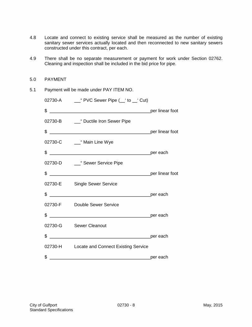
4.8 Locate and connect to existing service shall be measured as the number of existing
sanitary sewer services actually located and then reconnected to new sanitary sewers constructed under this contract, per each.
4.9 There shall be no separate measurement or payment for work under Section 02762.
Cleaning and inspection shall be included in the bid price for pipe. 5.0 PAYMENT 5.1 Payment will be made under PAY ITEM NO.
02730-A “ PVC Sewer Pipe ( ‘ to ‘ Cut) $ per linear foot 02730-B “ Ductile Iron Sewer Pipe $ per linear foot 02730-C “ Main Line Wye $ per each 02730-D “ Sewer Service Pipe $ per linear foot 02730-E Single Sewer Service $ per each
02730-F Double Sewer Service $ per each 02730-G Sewer Cleanout $ per each 02730-H Locate and Connect Existing Service $ per each
City of Gulfport 02730 - 8 May, 2015 Standard Specifications

02731 . . . . . . . . . . . . . . . . . . . . . . . . . . . . . . . . . . . . . . . . . . . . . . . . . . . . . . . . . . . . . . . MANHOLES 1.0 SCOPE OF WORK 1.1 This work shall consist of all labor, materials, and equipment to install precast manholes
as designated in these specifications and in reasonably close conformity with the lines and grades specified on the plans.
1.2 Specified elsewhere: Gravity Sewer Pipe – 02730
2.0 MATERIALS
2.1 Precast concrete risers, eccentric cone sections, flat slab top (where required), base
section, and adjusting rings shall conform to the requirements of ASTM Designation C-478. Manholes will have a minimum wall thickness of 5 inches, a minimum base thickness of 6 inches, and a minimum base diameter 12 inches greater than the outside diameter of the riser section. Both cone shaped top sections and flat slab tops shall be designed to withstand H-20 wheel loadings in accordance with AASHTO requirements. The nominal inside diameter of manholes shall be 48 inches, unless otherwise designated.
2.2 Joints shall be sealed with either a preformed joint compound or a rubber gasket.
Preformed joint compound shall meet Federal Specification SS-S00210 (210-A) and AASHTO Specification M-198. Rubber gaskets shall meet ASTM Designation C-443.
2.3 Castings 2.3.1 Standard castings shall consist of cast iron frames and covers shall conform to the plans
in all essentials of design. All castings shall be made of clean, even grain, tough gray cast iron. The quality of iron in the castings shall conform to the current ASTM Specification A-48 for Class 30 Gray Iron Castings. Frames and covers shall weigh not less than that shown on the plans. The castings shall be smooth, true to pattern and free from projections, sand holes or defects and shall properly fit the manhole opening. The portion of the frame and cover which forms the cover seal shall be machined so that no rocking of the cover is possible. The castings shall be coated with coal tar pitch varnish. The cover shall have non-penetrating pick holes. Standard castings shall be DF-24 Manhole Ring and Cover as manufactured by Dews Foundry, model no. V-1339 as manufactured by East Jordan Iron Works, Inc., or an approved equivalent. All manholes shall be furnished with standard castings unless otherwise specified on the plans.
2.3.2 At locations designated on the plans, watertight type manhole frame and cover sets shall
be provided. Covers and frames shall be manufactured from Ductile Iron in accordance with ISO 1083. Covers shall be one-man operable using standard tools and shall be capable of withstanding an average load of 100,000 lbs. Frames shall be circular and shall incorporate a sealing gasket. Cover shall withstand pressure of 14 psi positive and negative. The flange shall incorporate bedding slots and bolt holes. Cover shall be held in place by six clamping claws with fully enclosed bolts. Frames shall provide a minimum inside dimension of 24 inches and a frame depth of 4 inches. All components shall be black coated. Manhole frame and cover sets shall be “PAMTIGHT” as manufactured by Saint Gobain Canalisation or equal.
City of Gulfport 02731 - 1 May, 2015 Standard Specifications

2.2.3 All manhole covers shall be marked “SEWER” or “SANITARY SEWER”. 2.3.4 Castings shall be sealed to manhole with a preformed joint compound. Preformed joint
compound shall meet Federal Specification SS-S00210 (210-A) and AASHTO Specification M-198.
2.4 Manhole steps are required in manholes over four feet in depth and shall have a minimum
tread width of 12 inches, 5 3/4 inch projection, integrally cast with manhole section, and constructed of 1/2 inch Grade 60 steel reinforcement encapsuled in a copolymer polypropylene plastic, molded to form a slip-proof manhole step. Steps shall be installed perfectly in line vertically for ease of access or egress.
2.5 Concrete (other than precast) shall conform to requirements for Class B concrete, MDOT
Standard Specifications. 2.6 Reinforcement shall be Grade 40 or Grade 60 billet steel conforming to ASTM A-615. 2.7 Coating / Waterproofing of all manholes shall be either of the following materials: 2.7.1 Coating for both the interior and exterior surfaces of all manhole walls, including both joint
surfaces between manhole sections, shall be a coal tar epoxy or other approved sealant. All precast concrete sections shall be prepared, coated, and cured at the manufacturer's plant prior to shipping. Minimum dry-film thickness shall be 20 mils. Material shall be Indurall Right Stuff 2100, Americoat No. 78, Koppers 300-M, or approved equivalent, applied in strict conformance with manufacturer’s recommendations.
2.7.2 Concrete waterproofing admixture shall be of the cementitious crystalline type that
chemically controls and permanently fixes a non-soluble crystalline structure throughout the capillary voids of concrete. The design shall include the use of the crystalline waterproofing repair materials that generate a non-soluble crystalline formation in the concrete. The admixture shall contain a dye for visual detection. Materials shall be as manufactured by Xypex Chemical Corporation, applied in strict conformance with manufacturer’s requirements.
2.8 One hundred percent (100%) solids epoxy shall or 100% solids polyurethane be in
accordance with this paragraph, and shall be paid for in addition to the manhole.Where indicated on the drawings, manholes will be coated with an interior protective coating system to be field-applied to all interior surfaces of the designated manholes, in lieu of the interior coal tar epoxy system. The coal tar epoxy system shall still be applied to the exterior surfaces of the manholes as specified above. The interior protective coating system shall be an approved one hundred percent (100%) solids epoxy coating system or one hundred percent (100%) solids polyurethane, which is specifically recommended by the coating manufacturer to protect concrete and other surfaces against corrosion from hydrogen sulfide gas and other substances common in raw domestic sewage.
2.8.1 The 100% solids epoxy coating system product must have the following minimum
characteristics: a. Minimum Compressive Strength per ASTM D695 = 12,000 psi b. Minimum Tensile Strength per ASTM D638 = 7,200 psi
City of Gulfport 02731 - 2 May, 2015 Standard Specifications

c. Minimum Flexural Strength per ASTM D790 = 13,000 psi d. Minimum Adhesive Strength per ASTM C882 = 11,000 psi e. Minimum Bond Strength per ASTM D4541 = 900 psi f. Minimum Corrosion Resistance per ASTM D543 = pH 0.5 or higher 2.8.1.1 Product shall be Warren Environmental System one hundred percent (100%) Solids
Epoxy, Raven 405 Lining System or an approved equivalent. 2.8.2 The 100% solids polyurethane coating system product must have the following minimum
characteristics: a. Minimum Compressive Strength per ASTM D695 = 14,000 psi b. Minimum Tensile Strength per ASTM D638 = 7,500 psi c. Minimum Flexural Strength per ASTM D790 = 12,000 psi d. Minimum Bond Strength per ASTM D4541 = 900 psi e. Minimum Corrosion Resistance per ASTM D543 = pH 0.5 or higher
2.8.2.1 Product shall be Sprayoq Spraywall, or an approved equivalent. 2.8.3 A minimum thickness of one hundred fifty (150) mils of one hundred percent (100%)
Solids Epoxy or Solids Polyurethane shall be applied where specified. 2.9 Flexible watertight manhole pipe connectors shall be provided at all pipe openings and
shall consist of a neoprene rubber boot designed to clamp securely into an opening in the manhole wall and to clamp around the barrel of the sewer pipe. Openings in the manhole wall shall be made by a coring machine or by a hole former during the manufacturing process. Rubber material shall conform to the requirements of ASTM C-923 and be a minimum of 3/8 inches thick. External and internal clamps shall be all type 304 stainless steel conforming to ASTM A-167. Gasket shall be similar to "Kor-N-Seal Boot" as manufactured by the National Pollution Control Systems, Inc., Milford, New Hampshire, or approved equal.
2.10 Water stops shall be commercially available rubber, employing ribs to engage the PVC
pipe and large fins to engage the grout. The stop ring shall be clamped to the pipe by an all-stainless steel worm clamp.
2.11 Where a new sewer main is to be proposed to be connected to an existing manhole,
regardless if the existing pipe is smaller than the new proposed main, the contractor shall core the existing manhole to the appropriate diameter for the new main and shall furnish a flexible pipe to manhole connector similar to "Kor-N-Seal Boot" as manufactured by the National Pollution Control Systems, Inc., Milford, New Hampshire, or approved equal.
2.12 Manholes located within pavement shall have the cone elevation adjusted by utilizing
HDPE manhole adjusting rings with a butyl sealant placed between each additional adjusting ring installed. The rings shall be installed per the manufacturer’s recommendation. The HDPE adjusting rings shall be Ladtech, Inc. or an approved equivalent.
3.0 CONSTRUCTION REQUIREMENTS 3.1 Excavation for manholes shall conform to same requirements as adjoining sewers to
City of Gulfport 02731 - 3 May, 2015 Standard Specifications

which they are connected. No additional allowance in allowable trench width will be made for manholes and cleanouts.
3.2 In some cases, existing manholes within the allowable construction limits will be removed
to allow installation of new pipe, manholes, and facilities. In this case, the removal and disposal of those existing manholes shall be included in this item. Where existing pipes are partially removed, the exposed ends shall be completely plugged with bricks and mortar, at no additional compensation.
3.3 Precast manhole base sections shall be set, true and plumb, on a prepared, firm
subgrade, free of water. When the native subgrade material encountered consists of a material deemed by the Project Engineer to be unsuitable, the Contractor shall excavate an additional 12 inches and replace with limestone, Class A-610. The native material and/or the limestone base material under manholes will be completed to 95% Standard Proctor Density.
3.4 The method of joining precast concrete riser and cone sections shall be such that the ends
are fully entered and the inner surfaces are reasonably flush and even. The finished manhole shall be free of visible evidence of leakage. Not more than two (2) adjusting rings shall be allowed per manhole.
3.5 Where necessary to construct a manhole with a poured-in-place bottom, it shall be not
less than 12 inches thick and not less than 12 inches in diameter larger than the outside of the precast riser section conforming to details shown in the plans.
3.6 Reinforcement shall conform accurately to the dimensions and details indicated on the
drawings. Before being placed in any concrete work, it shall be cleaned thoroughly of all rust, mill scale, mortar, oil, dirt, or coating of any character which would be likely to destroy, reduce or impair its proper bonding with the concrete.
3.7 Concrete shall conform accurately to the dimensions and details indicated on the plans.
Concrete shall not be permitted to fall more than six feet without the use of pipe or tremies at least six inches in diameter. Concrete shall be thoroughly consolidated in a manner that will encase the reinforcement and inserts, fill the forms, and produce a surface or even texture free of rock pockets and excessive voids.
3.8 Contractor shall form invert channels smooth and shape to semi-circular bottom
conforming to the inside of the adjacent sewer section. Inverts shall extend up at least half of the diameter of the pipe. Changes in direction of the sewer and entering branches shall have a true curve of as large a radius as the size of the manhole will permit.
3.9 The annular space between the pipe and the pipe entry gasket boot shall be sealed at the
interior of the manhole to be flush and uniform with the interior manhole wall with a manufactured rubber sealer ring, grout, or by other approved means to prevent invert grout or debris from entering the boot.
3.10 Lifting holes in manhole walls shall be sealed with a non-shrink grout and shall have no
visible evidence of leakage. 3.11 Manhole steps shall be a straight alignment so as to form a continuous ladder with a
maximum distance of 14 inches between steps.
City of Gulfport 02731 - 4 May, 2015 Standard Specifications

3.12 Manhole frame casting shall be set on a preformed joint compound on top of concrete
cone section or adjusting ring, to line and grade, and in such a manner that subsequent adjustments will not be necessary. On paved streets, the frame and cover shall be set flush with and in the plane of the final paved surface course.
3.13 Watertight castings shall be provided for manholes at locations designated in the
Drawings. 3.14 Backfill may proceed as soon as manholes have developed sufficient strength to resist
backfilling loads and forces. Backfill for manholes shall be in the same manner as the adjoining sewers to which they are connected.
3.15 Where indicated on the plans, drop manhole connections shall be assembled using pipe
and fittings of the same type as the sewer main and in accordance with the details in the Drawings.
3.16 Connection to Existing System
3.16.1 The point at which the proposed system is to be connected to existing lines are designated
on the plans. Connections shall be made into existing lines at existing manholes or by construction of new manholes over existing lines. When the plans indicate connections to existing manholes, these connections shall be watertight and all work performed in an acceptable manner. Openings thru manhole walls shall be bored or shall be made with a small pneumatic device. Use of mauls or large pneumatic hammers likely to crack the manhole wall is prohibited. The size of the opening cut in the existing manhole wall shall be restricted to a nominal diameter sufficient only to insert the sewer pipe. After insertion of the sewer pipe, the void between the outside of the pipe and the manhole wall shall be packed with a non-shrink grout. There should be NO leakage through this wall connection.
3.16.2 The Contractor shall not interfere with the functioning of the existing sewers and shall not
allow debris to enter these sewers as a result of his work. When sewage flow quantities in the existing system are large and/or when the time of interruption of flow affects the operations of upstream mains and service lines, by-pass pumping will be necessary. No discharge will be permitted onto surface areas. No separate pay item will be allowed for bypass pumping.
3.17 Protective Coating System 3.17.1 All interior surfaces of designated manholes, as indicated on the Drawings, shall be field
coated with an approved coating system to protect it from Hydrogen Sulfide gases and other substances common in raw domestic sewage. It is the intent of this specification to achieve a complete monolithic coating across all joints and connections within the manhole.
3.17.2 The coating shall be applied absolutely in full accordance with the manufacturer's
recommendations for surfaces to be exposed to raw sewage. Installation procedures shall include: 1. Pre-coat inspection and procedures to eliminate any visible gaps or active leaks.
Active leaks shall be sealed using a suitable rapid-setting material, compatible with other materials to be used.
City of Gulfport 02731 - 5 May, 2015 Standard Specifications
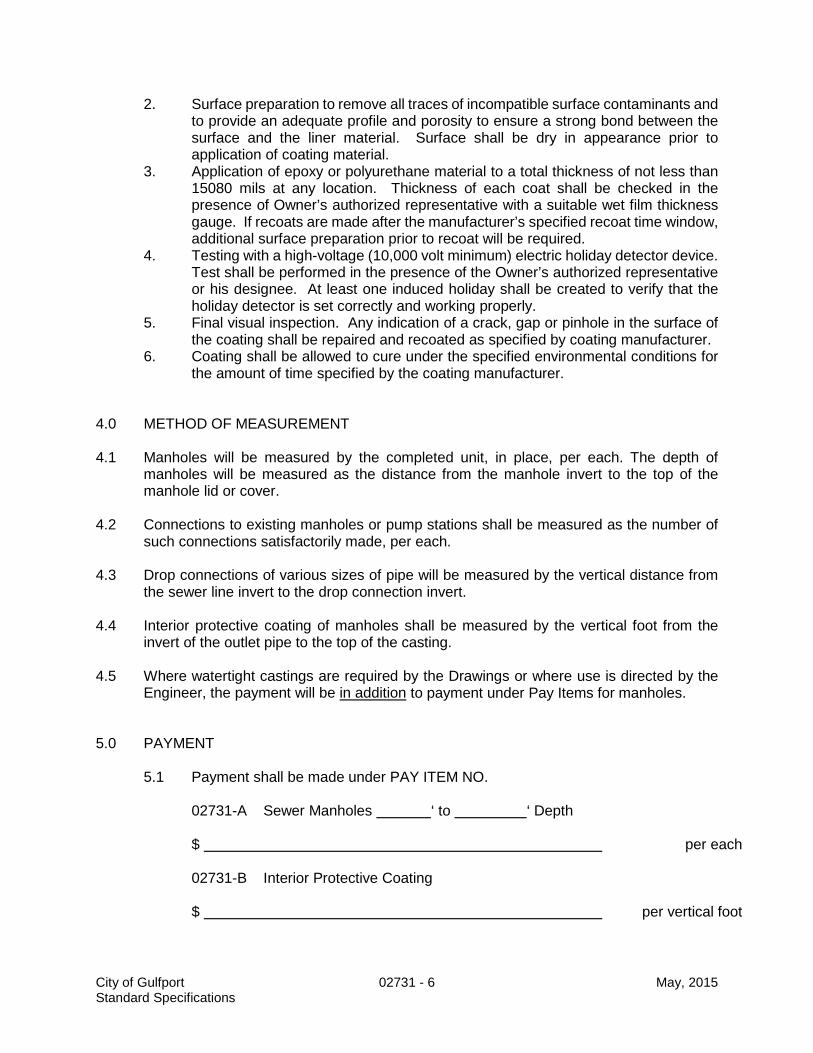
2. Surface preparation to remove all traces of incompatible surface contaminants and to provide an adequate profile and porosity to ensure a strong bond between the surface and the liner material. Surface shall be dry in appearance prior to application of coating material.
3. Application of epoxy or polyurethane material to a total thickness of not less than 15080 mils at any location. Thickness of each coat shall be checked in the presence of Owner’s authorized representative with a suitable wet film thickness gauge. If recoats are made after the manufacturer’s specified recoat time window, additional surface preparation prior to recoat will be required.
4. Testing with a high-voltage (10,000 volt minimum) electric holiday detector device. Test shall be performed in the presence of the Owner’s authorized representative or his designee. At least one induced holiday shall be created to verify that the holiday detector is set correctly and working properly.
5. Final visual inspection. Any indication of a crack, gap or pinhole in the surface of the coating shall be repaired and recoated as specified by coating manufacturer.
6. Coating shall be allowed to cure under the specified environmental conditions for the amount of time specified by the coating manufacturer.
4.0 METHOD OF MEASUREMENT
4.1 Manholes will be measured by the completed unit, in place, per each. The depth of
manholes will be measured as the distance from the manhole invert to the top of the manhole lid or cover.
4.2 Connections to existing manholes or pump stations shall be measured as the number of
such connections satisfactorily made, per each. 4.3 Drop connections of various sizes of pipe will be measured by the vertical distance from
the sewer line invert to the drop connection invert. 4.4 Interior protective coating of manholes shall be measured by the vertical foot from the
invert of the outlet pipe to the top of the casting. 4.5 Where watertight castings are required by the Drawings or where use is directed by the
Engineer, the payment will be in addition to payment under Pay Items for manholes.
5.0 PAYMENT
5.1 Payment shall be made under PAY ITEM NO.
02731-A Sewer Manholes ‘ to ‘ Depth
$ per each
02731-B Interior Protective Coating
$ per vertical foot
City of Gulfport 02731 - 6 May, 2015 Standard Specifications
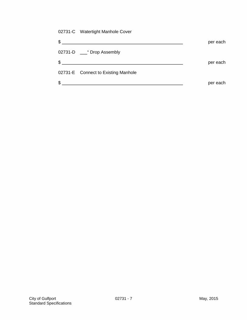
02731-C Watertight Manhole Cover
$ per each 02731-D “ Drop Assembly
$ per each 02731-E Connect to Existing Manhole
$ per each
City of Gulfport 02731 - 7 May, 2015 Standard Specifications

02732 .................................................................................... PRECAST SEWAGE PUMP STATION 1.0 SCOPE OF WORK 1.1 This work shall consist of all labor, materials, equipment, tools and services
required for the furnishing, installing and testing of precast wet pit type sewage pump stations, including related controls, operation devices, piping, valves and related appurtenances, and all related site construction shown on the site plan in accordance with these specifications and as detailed in the Drawings.
1.2 Specified Elsewhere: Pressure Sewer Main & Appurtenances –
Section 02733 Gravity Sewer Pipe - Section 02730
Manholes - Section 02731 Granular Base Course (Limestone) – Section 02234 2.0 MATERIALS 2.1 Wet Pit 2.1.1 Large diameter precast concrete round manhole and flat slab top conforming to
ASTM C-478. For superior resistance to sewer gases, cement shall be Portland Cement Type II, and course aggregates shall be crushed limestone. Wet Pits shall be 72 inches (6 ft.) or larger in diameter.
2.1.2 Joints for the precast concrete sections shall be tongue and groove and shall be
sealed with a preformed joint compound conforming to Federal Specification SS-S00210 (210-A) and ASHTO Specification M-198.
2.1.3 Coating for all exterior surfaces of new wet wells, including both joint surfaces
between sections, shall be a coal tar epoxy or other approved sealant. All precast concrete sections shall be prepared, coated, and cured at the manufacturer’s plant prior to shipping. Minimum dry-film thickness shall be 20 mils. Material shall be Indurall Right Stuff 2100, Americoat No. 78, Koppers 300-M, or approved equivalent, applied in strict conformance with manufacturer’s recommendations.
2.1.4 Interior protective coating system to be field-applied to all interior surfaces of all
new wet wells, certain existing wet wells to be renovated as designated in the Drawings, including all discharge piping inside the wet wells, and concrete manholes at locations shown in the Drawings, shall be an approved 100% solids epoxy coating system which is specifically recommended by the coating manufacturer to protect concrete and other surfaces against corrosion from Hydrogen Sulfide gas and other substances common in raw domestic sewage.
1. The product must have the following minimum characteristics:
a. Minimum Compressive Strength per ASTM D695 = 12,000 psi b. Minimum Tensile Strength per ASTM D638 = 7,200 psi c. Minimal Flexural Strength per ASTM D790 = 13,000 psi
City of Gulfport 02732 - 1 May, 2015 Standard Specifications

d. Minimum Bond Strength per ASTM D4541 = 900 psi e. Minimum Corrosion Resistance per ASTM D543 = pH 0.5 or higher.
2. Product shall be Warren Environmental System 100% Solids Epoxy, Raven 405 Lining System, or approved equal.
2.1.5 Flexible watertight manhole pipe connectors shall be provided at all pipe
openings and shall consist of a neoprene rubber boot designed to clamp securely into an opening in the manhole wall and to clamp around the barrel of the sewer pipe. Openings in the manhole wall shall be made by a coring machine or by a hole former during the manufacturing process. Rubber material shall conform to the requirements of ASTM C-923 and be a minimum of 3/8 inches thick. External and internal clamps shall be all type 304 stainless steel conforming to ASTM A-167. Gasket shall be similar to "Kor-N-Seal Boot" as manufactured by the National Pollution Control Systems, Inc., Milford, New Hampshire, or approved equal.
2.1.6 Water stops shall be commercially available rubber, employing ribs to engage the
PVC pipe and large fins to engage the grout. The stop ring shall be clamped to the pipe by an all-stainless steel worm clamp.
2.1.7 Vent pipe assembly shall be 4" minimum stainless steel pipe with stainless steel
screen or aluminum pipe with an aluminum screen. 2.1.8 Access hatches shall be aluminum frame of 1/4" thick, one-piece extruded
aluminum designed for embedment in a concrete slab. Door panel shall be 1/4" thick aluminum diamond plate, to withstand a live load of not less than 300 P.S.F., with a safety factor of 3. Hinges and all hardware shall be stainless steel. Doors shall hold open at 90 degrees and provisions shall be provided to lock the door in the closed position. Door shall close flush with the top of the frame, which shall be installed flush with the concrete slab, and provided with a locking mechanism in the closed position. Manufacturer shall apply bituminous coating to exterior of frame where in contact with concrete. Frames and covers shall be furnished with a written 10-year guarantee against defects in materials and/or workmanship. Doors shall be similar to Type SD150 as manufactured by Halliday Products, Orlando, Florida, Type K as manufactured by the Bilco Company, New Haven, Connecticut, or approved equal.
2.2 Valve Pit 2.2.1 All discharge valves and check valves shall be in a valve pit. The valve pit will
have a concrete bottom with concrete or masonry sides. 2.2.2 A drain from the bottom of the valve pit to the well pit will be installed to allow
drainage of rainwater. The bottom of the valve pit will be sloped to allow for proper drainage.
2.2.3 The valve pit will be of sufficient size to allow for maintenance of the valves
enclosed. This includes sufficient space to remove the check valve shaft from either side.
City of Gulfport 02732 - 2 May, 2015 Standard Specifications

2.2.4 Access to the valve pit will be through a hatch meeting the same specifications of the wet pit hatch or 1” x 4” galvanized grating where allowed.
2.2.5 All hardware in the valve pit will be stainless steel unless specifically stated otherwise.
2.3 Fall Protection System / Emergency Extraction System 2.3.1 All wet well lids will have a three (3) inch diameter hole either cast into the lid or
made by a coring machine, for use with the fall protection / emergency evacuation system. The center of the hole will be no less than fifteen (15) inches from the edge of the wet well access hatch.
2.4 Concrete and Masonry Structures 2.4.1 Concrete (used where not exposed to sewer gases) shall conform to Mississippi
Department of Transportation Standard Specification, Class B. 2.4.2 Reinforcing steel shall be grade 40 or grade 60 billet steel conforming to ASTM
A-615. 2.4.3 Steel wire fabric shall conform to the requirements of the Standard Specifications
for Welded Steel Wire Fabric for Concrete Reinforcement, AASHO Designation: M-55.
2.4.4 Curing materials shall conform to the requirements set out in the Standard
Specifications for Liquid Membrane Forming Compounds for Curing Concrete, AASHO Designation: M-148, Type 2 (White Pigmented).
2.4.5 Expansion joint material shall conform to Standard Specifications for Preformed
Expansion Joint Fillers for Concrete (non-extruding and resilient types), AASHO Designation M-213.
2.4.6 Concrete Masonry Units (CMU) shall conform to ASTM C-90, Grade N, Type I, shall be hollow, 8" X 16" blocks.
2.4.7 Mortar shall be one (1) part Portland Cement, three (3) parts Mortar Sand,
Hydrated Lime in proportion of one-tenth (1/10) part of volume of the cement and sufficient water to provide consistency so that it can be easily handled and spread with a trowel.
2.4.8 Valve vault cover shall be as specified above for access hatches. 2.5 Sewage Pumps and Motors 2.5.1 Required type and number of pumping units shall be as shown in the drawings.
Each pump and motor unit shall be of the fully submersible type, capable of discharging raw, unscreened sewage at the rate, head conditions, maximum pump speed, motor horsepower as shown on the schedules in the Drawings. Motors shall operate on 3 phase, 60 hertz, 240 / 480 VAC current, unless otherwise designated in the Drawings.
2.5.2 Each unit shall be equipped with a single hypalon jacketed type SPC electric
City of Gulfport 02732 - 3 May, 2015 Standard Specifications

cable suitable for submersible pump applications. The power cable shall be sized according to NEC and ICEA standards, and shall contain conductors for the power leads and all control functions.
2.5.3 The pump impeller shall be cast iron, dynamically balanced, and shall easily pass
a 3 inch diameter solid sphere. The impeller shall be keyed to the motor shaft and secured by a bolt.
2.5.4 All internal case clearances shall equal the discharge pipe diameter so that any
object which can enter the pump and pass through the discharge can pass through the pump without clogging.
2.5.5 Each pump shall be of the centerline flanged discharge type and shall be
supplied with a mating cast iron discharge elbow and base, which shall be permanently installed in the wet well along with the discharge piping. The pump shall be simply and automatically connected to the discharge elbow when lowered into place without need for personnel to enter the wet well. Sealing of the pump to the discharge elbow shall be accomplished by a simple linear downward motion of the pump resulting in a tight metal-to-metal connection without reliance of diaphragms, O-rings, or other sealing devices. The pump shall be positively guided into position by two (2) stainless steel guide rails (minimum 1 ¼” diameter), extending from the pump base to the access hatch frame.
2.5.6 Major pump components shall be of gray cast iron, Class 30, without visible
irregularities. All exposed hardware shall be of type 304 or 316 stainless steel or brass. All surfaces in contact with wastewater shall be ceramic coated, using Ceram (www.ceram-kote.com) or approved equal. Watertight seals between pump sections shall be made with nitrile rubber O-rings between machined and fitted surfaces.
2.5.7 Each pumping unit shall include a large stainless steel pull-up lifting ball with a
fixed connection to the motor housing and designed with adequate strength to lift the entire pumping unit.
2.5.8 The entire pump assembly shall be capable of continuous satisfactory operation
submerged to a depth of 65 feet. 2.5.9 Pumping units which utilize and depend on recirculation of the pumped media for
cooling purposes or provide connections for external cooling water are not acceptable.
2.5.10 Each pump shall be provided with a tandem mechanical shaft seal system, each
of which shall be independently capable of sealing the pumped liquid from the stator housing. The upper seal shall consist of a stationary tungsten carbon ring and a driven carbon ring. The lower seal shall consist of two (2) tungsten carbon rings. Each pump shall contain a detecting probe which shall activate its respective “moisture detect” pilot light on the control panel.
2.5.11 The pump motor shall be a squirrel-cage, induction, shell type design, without
brushes or other arc-producing mechanisms, and shall be designed for
City of Gulfport 02732 - 4 May, 2015 Standard Specifications

submersible service in water or raw sewage. The unit shall be listed with Underwriters Laboratories for use in Class I, Group D, Division I locations (explosion proof). All electric parts shall be housed in an air-filled, watertight enclosure, separated from the outside with two (2) “O” ring seals and rabbet joints with a large overlap. One seal shall be inside an oil chamber, and one outside.
2.5.12 Two internal moisture sensing probes shall detect any leakage of a conductive
liquid past the outer seal, to provide a warning of seal failure. Cable leads shall be sealed with epoxy.
2.5.13 The motor shaft and all external hardware including the motor nameplate shall be
of stainless steel. Motor bearings shall be pre-lubricated at the factory for a long maintenance-free service life. Bearings shall be designed to resist high thrust loads.
2.5.14 Motor windings shall employ a Class B insulation with Class F materials.
Automatically resetting thermal overloads shall be installed in adjacent phases of the motor winding for protection against overheating.
2.5.15 The pump manufacturer shall warrant to the Owner the pumping units against
defects in workmanship and material for a period of five years or 10,000 hours under normal municipal use.
2.5.16 The pump manufacturer or supplier must have qualified field service
representatives readily available for hire by Contractor or the Owner for consultation and/or repair services. Replacement parts and components for the supplied pumps shall be available from manufacturer's stock, ready for immediate shipment upon order.
2.5.17 Sewage pumps shall be as manufactured by WEMCO, ESSCO, or approved
equivalent, and shall meet each of the specified performance requirements stated in the Drawings.
2.5.18 The actual pumping units to be furnished shall each be tested prior to shipment
to the job site. Each pump shall be tested at a facility provided by the pump manufacturer in accordance with the standards of the Hydraulic Institute. Flow, head, motor current draw, and input KW shall be measured and recorded for operating conditions throughout the head/capacity range for the pump, including at "Shutoff", design flow with one pump operating, and minimum ("worst case") TDH (see system head curves tabulated in Drawings). Certified test reports shall be furnished with each pump. The Owner and/or Engineer reserve the right to witness the pump tests and/or arrange for the services of an independent testing laboratory to witness the pump tests at the pump manufacturer's facility.
2.5.19 After field installation, the Contractor shall perform flow testing to verify that each
pump performs according to its certified curve. The Contractor shall furnish all equipment and materials required for the flow test.
2.5.20 Full operation and maintenance manuals and parts lists shall be provided in
triplicate.
City of Gulfport 02732 - 5 May, 2015 Standard Specifications

2.6 Station Piping and Valves 2.6.1 Ductile iron pipe shall conform to ANSI A21.51 (AWWA C-151) thickness Class
50, cement mortar lined per ANSI A21.4 (AWWA C-104). 2.6.2 Ductile fittings shall conform to ANSI A21.10 (AWWA C-110), cement mortar
lined per ANSI A21.4 (AWWA C-104). 2.6.3 Gaskets for ductile iron pipe shall conform to material requirements of ANSI A-
21.11 mechanical joint gaskets, suitable for water working pressures of up to 350 p.s.i.
2.6.4 Gate valves shall be of the resilient seat type, conforming to AWWA C-509,
epoxy coated inside and outside to AWWA C-550. End connections shall be Class 125 flange. Valves shall be rated for zero leakage to 200 p.s.i., and 400 p.s.i. hydrostatic test pressure. Valves shall be of the non-rising stem design, employing two O-ring stem seals. Gates shall be encapsulated in rubber where exposed to line velocity and shall be field replaceable. Hand wheels shall be provided.
2.6.5 Check valves shall be "Full-Flow", bronze clapper design utilizing outside lever
and weight or spring, conforming to AWWA C-508. Check valves will have the ability to mount lever on either side. Check valves shall be positioned in the valve vault such that the flapper shaft may be removed without removing the check valve itself.
2.6.6 Isolation gate valves, not located in the valve vault shall have a valve box. 2.6.7 Plug Valves shall be of the tight closing, resilient faced, non-lubricating variety
and shall be of eccentric design such that the valves pressure member (plug) rises off the body seat contact area immediately upon shaft rotation during the opening movement. Valves shall be drop-tight at the rated pressure (175 psi through 12”, 150 psi 14” and above) and shall be satisfactory for applications involving throttling service as well as frequent or infrequent on-off service. The valve closing member should rotate approximately 90 degrees from the full-open to full-close position and vice-versa. The valve body shall be constructed of cast iron (semi-steel) conforming to ASTM A126, Class B. Body ends shall be flanged with dimensions, facing, and drilling in full conformance with ANSI B 16.1, Class 125, this including flange thickness. Mechanical Joint to meet the requirements of AWWA C111/ANSI A21.11. Eccentric Plug Valves shall have a rectangular shaped port. Port areas for 3” through 20” valves shall be a minimum 80% of full pipe area. Valve seat surface shall be welded-in overlay, cylindrically shaped of not less than 90% pure nickel. Seat area shall be raised, with raised area completely covered with weld to insure proper seat contact. The machined seat area shall be a minimum of .125” thick and .500” wide. The valve plug shall be constructed of cast iron (semi-steel) conforming to ASTM A126, Class B. The plug shall have a cylindrical seating surface that is offset from the center of the plug shafts. The plug shafts shall be integral. The entire plug shall be 100% encapsulated with Buna-N rubber in all valve sizes. The rubber compound shall be approximately 70 (Shore A) durometer hardness. The rubber
City of Gulfport 02732 - 6 May, 2015 Standard Specifications

to metal bond must withstand 75 lbs. pull under test procedure ASTM D-429-73 Method B.
2.6.8 Pressure gauges shall measure from 0 - 60 P.S.I., and also in corresponding feet
of water. Pressure gauges shall be oil filled. 2.6.9 All hardware in the wet well and valve vault shall be stainless steel unless
specifically stated otherwise. 2.6.10 All stations will have emergency bypass piping installed. A Valve on the force
main and bypass line will be installed and the bypass connection will be located above grade sealed with a blind flange.
2.6.11 Pressure gauges shall measure from 0 – 60 psi and also in corresponding feet of
water. Gauges shall be oil filled.
2.6.12 Guide rails shall be schedule 40 stainless steel.
2.6.13 All hardware in the wet well and valve pit shall be stainless steel unless specifically stated otherwise.
2.7 Pump Control System 2.7.1 An automatic Pump Control System shall be furnished to automatically operate
the sewage pumps in accordance with variation in the level of the wet well. The Control System shall employ either four (4) float switches, or a system with an electronic transducer and one high level float switch and specified as follows:
2.7.2 Float Switch System (Less Than 250 GPM or 15 hp Pumps) 2.7.2.1 The Control System shall employ four (4) float switches and a pump controller to
detect level control points in the wet well and operate the pump motor starters. No pump controls using mechanical linkage, cables, tapes, etc., between the float and control or using sliding floats, shall be considered.
2.7.2.2 Float switches shall be of Type 316 stainless steel, 5-½ inch diameter. Cable
shall be forty (40) feet in length, Type SO with Nitrile PVC jacket, containing three (3) #14 AWG fine-stranded conductors for heavy flexing and underwater service. Floats shall contain a sealed mercury switch rated for 20 amps at 115 volts. Float switches shall be furnished complete with stainless steel clamp tube, bracket and bolts to clamp to vertical one (1) inch aluminum pipe, which is to be furnished and installed in wet well as detailed. Consolidated Model 9G float switch, Anchor Scientific Roto-Float-SS Type P, or an approved equal.
2.7.2.3 Floats will detect off, lead pump, lag pump and high level conditions. The high
level float will work independently of all other floats and, if in the up position, the alarm light will flash and SCADA will send a high level alarm, and turn one pump on.
2.7.2.4 The aluminum pipe with the float switches installed will be suspended vertically
from a hook in the wet well lid. It will be suspended from a hook with 3/16”
City of Gulfport 02732 - 7 May, 2015 Standard Specifications

stainless steel chain to permit extraction of the pole and float switches. 2.7.3 Electronic Transducer System (For 250 GPM or 15 hp Pumps or Greater) 2.7.3.1 The Control System shall employ an electronic transducer to monitor the liquid
level and one (1) high level float switch which shall activate the high level alarm and turn on one (1) pump.
2.7.3.2 Submersible pressure/level transducer (4 to 20 milliamp) shall be contained
within a rugged stainless steel housing and shall incorporate features, to protect the solid state sensor from viscous liquids and slurries, including raw sewage. Range shall be zero to 35 feet (0-15 psi). the excitation voltage and analog signal output shall be compatible with the digital meter/controller to be specified hereinafter. The operating temperature shall be from -40°F to 176°F. Sensor shall be furnished with polyethylene shielded cable, 50 feet in length. Transducer and cable shall be secured with stainless steel hook.
2.7.4 A pump controller/sequencer module shall use the signals generated from either
the Float Switch System or the Electronic Transducer System and shall incorporate the following features:
2.7.4.1 Level meter/controller shall be an electronic solid state proportional device which
accepts input from the previously specified submersible pressure/level transducer, conditions the signal, displays the level reading digitally, in feet, and performs discrete on/off contact closures at six (6) or more field-adjustable set-points. The setting of each set-point shall be able to be displayed on the digital readout at any time. A means shall be provided to manually ramp the meter/controller up and down through its entire range, to test the operation of the system.
2.7.4.2 A pump controller/sequencer module shall use the signals generated from either
the Float Switch System or the Electronic Transducer System and shall incorporate the following features:
2.7.4.3 Manual-Off-Automatic (H.O.A.) selector switch (momentary NOT allowed), green
running pilot light, red failure pilot light, and red seal failure pilot light for each pump on control panel.
2.7.4.4 A PUMP NO. 1 LEAD – ALTERNATE - PUMP NO. 2 LEAD sequence selector
switch to select either pump as lead pump or select that the pumps alternate as lead pump on each call for cycle.
2.7.4.5 A field adjustable failure time delay for each pump. Controls to start the lag
pump at the lead pump start level if the lead pump fails or if the lead pump selector switch is placed in the off position. If a pump fails, the remaining functional pump shall remain the lead pump on future cycles. The failure pump shall only be called to operate at the lag pump operating level. Normal pump alternation shall resume when failure condition is corrected and pump has been reset.
2.7.4.6 Soft stop feature to require the pumps to stop three (3) seconds apart during the
City of Gulfport 02732 - 8 May, 2015 Standard Specifications
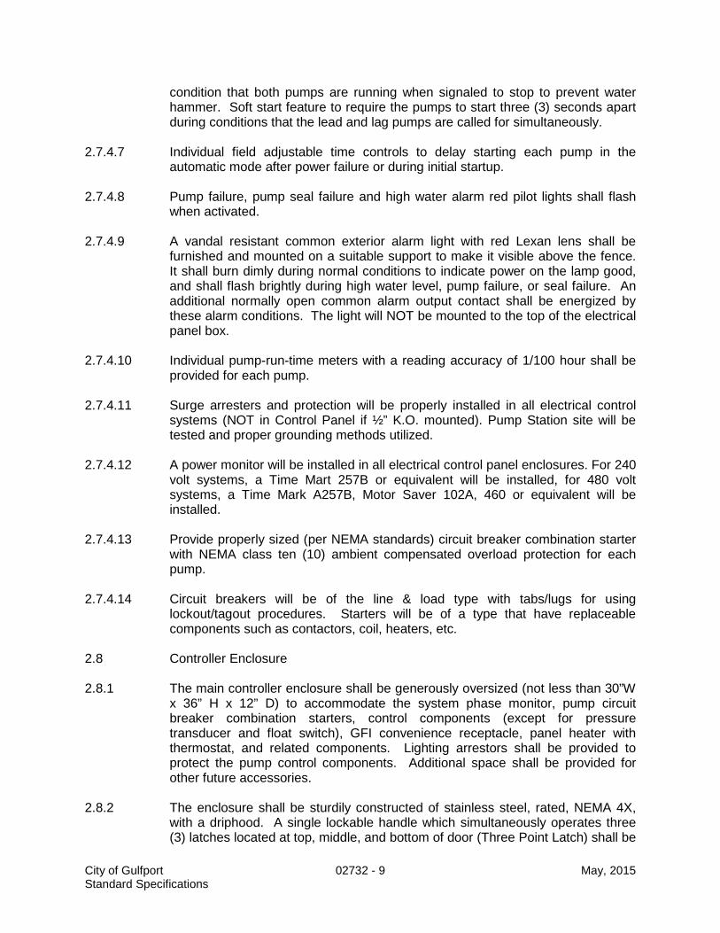
condition that both pumps are running when signaled to stop to prevent water hammer. Soft start feature to require the pumps to start three (3) seconds apart during conditions that the lead and lag pumps are called for simultaneously.
2.7.4.7 Individual field adjustable time controls to delay starting each pump in the
automatic mode after power failure or during initial startup. 2.7.4.8 Pump failure, pump seal failure and high water alarm red pilot lights shall flash
when activated. 2.7.4.9 A vandal resistant common exterior alarm light with red Lexan lens shall be
furnished and mounted on a suitable support to make it visible above the fence. It shall burn dimly during normal conditions to indicate power on the lamp good, and shall flash brightly during high water level, pump failure, or seal failure. An additional normally open common alarm output contact shall be energized by these alarm conditions. The light will NOT be mounted to the top of the electrical panel box.
2.7.4.10 Individual pump-run-time meters with a reading accuracy of 1/100 hour shall be
provided for each pump. 2.7.4.11 Surge arresters and protection will be properly installed in all electrical control
systems (NOT in Control Panel if ½” K.O. mounted). Pump Station site will be tested and proper grounding methods utilized.
2.7.4.12 A power monitor will be installed in all electrical control panel enclosures. For 240
volt systems, a Time Mart 257B or equivalent will be installed, for 480 volt systems, a Time Mark A257B, Motor Saver 102A, 460 or equivalent will be installed.
2.7.4.13 Provide properly sized (per NEMA standards) circuit breaker combination starter
with NEMA class ten (10) ambient compensated overload protection for each pump.
2.7.4.14 Circuit breakers will be of the line & load type with tabs/lugs for using
lockout/tagout procedures. Starters will be of a type that have replaceable components such as contactors, coil, heaters, etc.
2.8 Controller Enclosure 2.8.1 The main controller enclosure shall be generously oversized (not less than 30”W
x 36” H x 12” D) to accommodate the system phase monitor, pump circuit breaker combination starters, control components (except for pressure transducer and float switch), GFI convenience receptacle, panel heater with thermostat, and related components. Lighting arrestors shall be provided to protect the pump control components. Additional space shall be provided for other future accessories.
2.8.2 The enclosure shall be sturdily constructed of stainless steel, rated, NEMA 4X,
with a driphood. A single lockable handle which simultaneously operates three (3) latches located at top, middle, and bottom of door (Three Point Latch) shall be
City of Gulfport 02732 - 9 May, 2015 Standard Specifications

provided. No penetrations through the top of the enclosure will be permitted. 2.8.3 All selector switches, pilot lights, hours meters, and other controls shall be
mounted on an interior anodized aluminum or stainless steel deadfront panel with a continuous aluminum or stainless steel hinge. Circuit breakers shall be operable through the deadfront panel.
2.8.4 An automatic fluorescent panel light and thermostatically controlled electric panel
heater shall be installed within each enclosure. 2.8.5 A 110 volt GFI duplex receptacle shall be provided inside the control panel and
mounted through the interior dead front panel. 2.8.6 All electrical equipment (service meter, pump control panel, disconnect, transfer
switch, etc.) if freely mounted on a grid system such as uni-strut with rigid pipe as post, it shall be a minimum of 3-1/2” feet from wet wells edge.
*Note to Designer: Choose either Automatic or Real-Time System depending on floats
or transducer. Specify only one.
2.9 *SCADA System (Supervisory Control and Data Acquisition) (For use with pump stations using float switches):
2.9.1 The equipment shall be MISSION Communications Model RTU. Contractor’s bid
price shall include five (5) years of prepaid monitoring service, with no option for additional costs to be paid by Owner during this five (5) year period.
2.9.2 Full operation and maintenance manuals and parts lists shall be provided in
triplicate. 2.9.3 M unit will report the following:
a. Individual Pump Runtime b. Cumulative Pump Runtime c. High Level Alarm d. Pump Failure Alarm e. AC Power Fault Alarm f. Communications Failure Alarm
2.9 *Real-Time Alarm System (For use with pump stations using pressure
transducers) 2.9.1 The equipment shall be MISSION Communications Model 800 RTU.
Contractor’s bid price shall include five (5) years of prepaid monitoring service, with no option for additional costs to be paid by Owner during this five (5) year period.
2.9.2 M-800 unit will report the following:
a. Individual Pump Runtime
City of Gulfport 02732 - 10 May, 2015 Standard Specifications

b. Cumulative Pump Runtime c. High Level Alarm d. Pump Failure Alarm e. AC Power Fault Alarm f. Communications Failure Alarm
2.9.3 The M-800 will report in real time the status of pumps, communications, alarms,
wet well level. 2.9.4 Full operation and maintenance manuals and parts lists shall be provided in
triplicate. 2.10 Manual Transfer Switch 2.10.1 For stations with pumps 10 HP or greater, a three (3) position transfer switch that
allows Off, Auxiliary, and On positions. Switch will be mounted between power meter and control panel and will completely isolate electrical power to control panel when in any position other than On. Switch will be mounted in a NEMA 4X stainless steel enclosure.
2.11 Electrical Wiring 2.11.1 All electrical devices and wiring shall conform to applicable National, State, and
Local electrical codes. All equipment shall be new and shall bear the inspection label of the Underwriter’s Laboratories, Inc.
2.11.2 Primary power shall be either 240 or 480 volts, 3-Phase, as designated in the
drawings, with sufficient ampacity to power all electrical equipment without objectionable voltage drop.
2.11.3 All wiring shall be within rigid steel conduit of adequate size to freely receive the
wiring without binding. Conduit in concrete slabs or underground may be schedule 40 PVC (equipment ground conductor required).
2.11.4 Motor lead conduit will be a minimum of 2.0” diameter sized to freely receive the
wiring without binding, float switch conduit will be a minimum of 2.0” diameter and transducer lead will be a minimum of 1.0” diameter. Transducer shall have its own conduit.
2.11.5 Each conduit will have an approved seal off (NO PSI or DWV fittings) between
the control panel and wet well. Seal offs will contain chico (NOT duct seal or spray foam). Junction boxes are not allowed.
2.11.6 All conductors shall be copper with 600 volt, THW insulation or better. Minimum
conductor size shall be #12 AWG for lighting and power circuits and #14 AWG for control wiring. All motor leads, float switch leads and transducer leads will terminate in the control panel.
2.11.7 All wiring device cover plates shall be stainless steel or PVC and weatherproof.
Outside security lights shall be 100 watt, 110 volt metal halide dusk to dawn type fixture for pole mount and 50 watt 110 volt high pressure sodium or metal halide
City of Gulfport 02732 - 11 May, 2015 Standard Specifications

fixtures designated for surface mounting, complete with photo cell. The outside security light will have a separate circuit breaker located in the electrical panel box and will be accessible through the deadfront panel.
2.11.8 Service pole shall be Southern Yellow Pine, 25 feet minimum length, Class 5,
treated with Chromated Copper Arsenate (CCA) to not less than 0.60 pounds per cubic foot by ASSAY, with penetration not less than four (4) inches. Should service line to the pole span more than fifty (50) feet, a guy wire will be applied to the service pole.
2.12 Sitework 2.12.1 All pump stations will have a two (2) inch water service terminating within twenty
(20) feet of the wet pit. The stand pipe shall be a flush valve type stand pipe. The water service will terminate with a two (2) inch cam lock type fitting and a ¾” hose bib.
2.12.2 Water service tubing shall be polybutylene plastic conforming to ASTM 2666, or
polyethylene plastic conforming to ASTM 2737, NSF approved, dimensions to fit standard CTS fittings, SDR 9, 250 psi.
2.12.3 Crushed limestone for use as driveway material and surface at the pump station
site, for a minimum distance of ten (10) feet from the pump station wet well and valve vault structures (for inside the fenced area, if provided) as detailed in the drawings. Crushed limestone shall be dense-graded crushed domestic limestone, plant-mixed to conform to Size No. 610 or 825A, MDOT Specifications. A geotextile fabric shall be place under all limestone surfaces. The geotextile fabric shall be 600X as manufactured by Marifi or an approved equivalent.
2.12.4 Wood Fence 2.12.4.1 Wood boards shall be No. 2 grade, ¾” x 6” dog eared Western Red Cedar
fencing with three (3) strands of barbed wire or razor wire. Wood rails shall be No. 2 grade S4S Southern Pine pressure treated with waterborne salts in accordance with American Wood Preserves institute Standard C2 and bearing their quality mark LP2. Dry wood to ten (10) percent of less moisture content after treatment. Furnish treating material for treating cut ends.
2.12.4.2 Wood posts shall be 4” x 4” x 8” osmose treated timbers. Gate shall be two
piece, each Section 6” wide on 2 x 4 frame, cross braced with 2 x 4’s. Nails shall be #6 galvanized ring shank.
2.12.4.3 Bolts shall be ¼ inch galvanized A307 with washer and nut. 2.12.4.4 Hardware shall be black wrought iron. Hinges shall be eight (8) inch “T” hinge to
permit 180 degrees opening of gate. Latch shall be heavy duty hasp latch, capable of receiving of number 2 padlock. Concrete shall be approved ready mix source, 3,000 psi minimum.
2.12.5 Chain Link Fence
City of Gulfport 02732 - 12 May, 2015 Standard Specifications

2.12.5.1 Chain link fence will be minimum of six (6) feet high with three (3) strands of
barbed wire or razor wire. All posts and framing shall conform to schedule 20 galvanized steel. Steel wire shall be zinc coated fabric (galvanized after weaving) #9 gauge, 2” mesh required. Concrete shall be MDOT Class “B”.
3.0 CONSTRUCTION REQUIREMENTS 3.1 Excavation - General 3.1.1 Excavation shall include the clearing of the site of the work, the loosening,
loading, removing, transporting and disposing of all materials, wet or dry, above or below ground necessary to be removed for all construction included in this contract to the lines, grades and locations shown on the Drawings.
3.1.2 Mechanical excavation shall be stopped above the foundation base elevation so
that the concrete foundation may be constructed to a firm, undisturbed native earth bed.
3.1.3 The Contractor shall, at his own expense furnish and install all temporary
sheeting, timbering and bracing required to maintain the excavation in a condition to furnish safe working conditions and to permit the safe and efficient installation of all items of contract work. The Contractor shall further, at his own expense, shore up or otherwise protect all fences, buildings, walls, walks, curbs, or other property adjacent to any excavation which might be disturbed during the progress of the work.
3.1.4 Temporary supports must be removed by the Contractor at his own expense
after or concurrently with the completion of the permanent facility. 3.1.5 The Contractor shall do all ditching, pumping, well pointing and bailing, build all
drains, and do all other work necessary to keep the excavation clear of ground water, sewage or storm water during the progress of the work and until the finished work is safe from injury. Where the excavation is wet sand, and suitable construction conditions cannot be obtained by other methods, the Contractor shall install and operate, at his own expense, a pumping system connected with well points, so as to drain the same effectually. All well point holes shall be backfilled with sand after removal. No masonry or pipe shall be laid in water, and water shall not be allowed to rise over masonry until concrete or masonry has set at least 48 hours. All water pumped or drained from the work shall be disposed of in a manner that will not damage adjacent property or other work under construction. Necessary precautions shall be taken to protect all construction against flooding.
3.1.6 Whenever the excavation is carried beyond the lines and grades shown on the
Drawings, the Contractor shall, at this own expense, refill all such excavated space with such material and in such manner as may be directed.
3.1.7 Unsuitable and surplus excavated material not incorporated in the work shall be
disposed of by the Contractor at his own expense.
City of Gulfport 02732 - 13 May, 2015 Standard Specifications

3.1.8 In the event that any existing gas pipe, water pipes, conduits, sewers, tile drains
or poles are blocked or interfered with by the excavation required on this project, the Contractor shall maintain them in continuous operation. In case of unavoidable or accidental damage, notify utility owner. Water and sewer lines must be repaired by contractor.
3.2 Installation of Wet Well 3.2.1 Reinforcement shall conform accurately to the dimensions and details indicated
on the Drawings. Before being placed in any concrete work, it shall be thoroughly cleaned of all rust, mill scale, mortar, oil, dirt or coating of any character which would be likely to destroy, reduce or impair its proper bonding with the concrete.
3.2.2 Concrete shall conform accurately to the dimensions and details indicated on the
Drawings. Concrete shall not be permitted to fall more than 6 feet without the use of pipes or tremmies at least 6 inches in diameter. Concrete shall be thoroughly consolidated in a manner that will encase the reinforcement and inserts, fill the forms, and produce a surface of even texture free of rock pockets and excessive voids.
3.2.3 Install wet pit (concrete pipe), wet pit top, valve vault, equipment, piping and
related appurtenances in accordance with the details in the Drawings and as specified herein.
3.2.4 All openings cut into the walls of the wet pit liner for piping and conduit shall be
carefully grouted and sealed so that there is no visible evidence of infiltration. Provide a rubber water stop ring at all points where PVC pipes penetrate the wet well wall.
3.3 Mechanical 3.3.1 Pumps, piping, and fittings shall be fitted, assembled, and supported in a manner
to avoid strain upon the components. 3.3.2 Flanged connections shall be made up with full-sized bolts, without resorting to
prying to achieve proper alignment. 3.3.3 Installation of pumps and auxiliary equipment shall be as recommended by the
pump manufacturer. 3.4 Electrical 3.4.1 All electrical installation shall fully conform with all requirements of the National
Electrical Safety Code, the National Electrical Code and all other applicable codes, as well as the requirements specified herein.
3.4.2 Run exposed conduit parallel or perpendicular to supporting structure. Support
at intervals of five feet minimum. Underground installation shall be buried with a minimum cover of 12".
City of Gulfport 02732 - 14 May, 2015 Standard Specifications

3.4.3 No splices will be permitted in any conductors except within approved junction boxes at triplex or larger stations.
3.4.4 Slack loops of at least 18" in length shall be left in each conductor at each splice.
Slack loops of not less than 6" shall also be provided in each conductor within the pump controller enclosure.
3.4.5 Flexible electrical cables within the wetwell shall be supported by a suitable strain
relief device to allow disconnection from outside the wetwell. The pump power cable shall conform to the requirements of the Mine Safety and Health Administration for trailing cables. Ground fault interruption protection shall be used.
3.4.6 Paint all galvanized steel conduit in contact with earth with approved asphaltic
paint. 3.5 Concrete and Masonry 3.5.1 The concrete used in construction, where not exposed to sewer gases shall be
proportioned, mixed and placed in accordance with the provisions and requirements in the MSHD Standard Specifications, 1990 Edition, Section 804.05. Minimum 28-day compressive strength shall be 3000 p.s.i.
3.5.2 Forms shall be of wood or metal, straight, free from warp, of sufficient strength to
resist the pressure of the concrete without springing, and shall be cleaned thoroughly and oiled before concrete is placed against them. Bracing and staking of forms shall be such that the forms remain in both horizontal and vertical alignment until their removal.
3.5.3 Reinforcement shall be placed in exact positions shown on the plans and firmly
held during the placing and setting of concrete. Metal devices in contact with exterior surface of the structure shall be galvanized. The use of gravel, pieces of broken stone or brick, metal pipe and wooden blocks as spacers will not be permitted.
3.5.4 Surfaces shall receive a broom finish. After the final finish, but before the
concrete has taken its initial set, all edges shall be worked with an approved tool. 3.5.5 Cure with white pigmented liquid membrane, conforming to ASTM C-309 spray
uniformly at a rate of one gallon to not more than 150 square feet by mechanical sprayer immediately after finishing operation is completed.
3.5.6 Mortar not used within forty-five (45) minutes after water has been added will be
wasted. 3.6 Limestone 3.6.1 Crushed limestone mixture for use in driveway and access road areas shall be
placed upon a prepared subbase and compacted to 95% Standard Proctor Density to a uniform thickness of six (6) inches. The surface shall be graded and shaped to drain.
City of Gulfport 02732 - 15 May, 2015 Standard Specifications

3.6.2 Crushed limestone mixture for use at the pump station site in the locations as
indicated in the Drawings and as specified herein, shall be placed upon a prepared subbase and compacted to 95% Standard Proctor Density to a uniform thickness of six (6) inches. The surface shall be graded and shaped to drain.
3.7 Fence 3.7.1 Installation of fence shall be by skilled and experienced workmen in accordance
with the details in the Drawings. 3.7.2 All fencing shall be installed plumb. The top of the fence shall be level
throughout. All items to be set in ground shall be set in concrete. 3.8 General 3.8.1 All workmanship and materials throughout shall be of the highest quality. 3.8.2 Upon completion of work at site, remove excess excavation and restore
disturbed areas in such a manner as to insure positive drainage. Seed all disturbed areas and maintain to insure living growth of vegetation.
3.8.3 Contractor shall guarantee all materials, equipment, controls and structures for a
period of one year against defects in materials and workmanship. 3.8.4 Operation and maintenance manuals shall be provided in triplicate, for pumps,
motors, controls, and valves. 4.0 METHOD OF MEASUREMENT 4.1 Pump Stations shall be measured for payment as one lump sum for complete
sewage pump station in place, including all structures, pumps, electrical controls, valves, piping, fencing, site work, and related work as shown in the Drawings, and as specified herein. Partial payments will be allowed, based upon Engineer's estimation of the value of work completed.
5.0 PAYMENT 5.1 Payment shall be made under PAY ITEM NO.
02732-A Sewage Pump Station and Appurtenances $ per lump sum
City of Gulfport 02732 - 16 May, 2015 Standard Specifications

02733 ............................................................ PRESSURE SEWER MAIN & APPURTENANCES 1.0 SCOPE OF WORK 1.1 This work shall consist of all labor, materials, equipment, tools and services
required to furnish and install sewage force mains, fittings, valves, thrust blocks and restrained joints at sites and locations as designated in these specifications and in reasonably close conformity with the lines and grades specified in the Drawings.
1.2 Specified elsewhere: Precast Sewage Pump Station - Section 02732
Air Valves & Vaults for Sewer Pressure Mains - Section 02734
2.0 MATERIALS
2.1 Pipe: At Contractor's option, use any of the following acceptable materials unless otherwise designated on the plans:
2.1.1 Polyvinyl Chloride pipe (for nominal sizes up to and including 12 inches), with
integral expanded bells conforming to ASTM D-2241, SDR 26, 160 p.s.i. working pressure. Couplings or joints shall be an integral part of the pipe barrel. It shall consist of an expanded bell with grooves to retain a rubber sealing ring conforming to the requirements of ASTM D-1869.
2.1.2 Polyvinyl Chloride pipe conforming to AWWA C-900 (for nominal sizes up to and
including 12 inches), Standard dimension ratio shall be not more than 25. Pipe shall be made to cast iron O.D.'s. Each length of pipe shall be stamped with approval of Underwriter's Laboratories, Inc. Pipe couplings or joints shall be an integral part of the pipe barrel, consisting of an expanded bell with a groove to retain a rubber sealing ring. Gaskets shall be factory bonded into the groove.
2.1.3 Polyvinyl Chloride pipe conforming to Uni-Bell PVC pipe association Standard
Specification UNI-B-11-85 and AWWA C-905 (for nominal sizes greater than 12 inches). Standard dimension ratio shall be not more than 25. Pipe shall be made to cast iron O.D.'s. Each length of pipe shall be stamped with approval of Underwriter's Laboratories, Inc. Pipe couplings or joints shall be an integral part of the pipe barrel, consisting of an expanded bell with a groove to retain a rubber sealing ring. Gaskets shall be factory bonded into the groove.
2.1.4 Ductile Iron Pipe conforming to ANSI A-21.51 (AWWA C-151) Grade 60-42-10
Ductile Iron, thickness Class 50. Pipe interior shall be cement mortar lined per ANSI A.21.4 (AWWA C-104). Rubber gasket joints per ANSI A-21.11 (AWWA C-111).
2.2 Gate valves (16" and smaller) shall be of the "resilient seat" type, conforming to
AWWA C-509, epoxy coated inside and outside to AWWA C550. End connections shall be standard mechanical joint, complete with restrained glands as specified herein. Valves shall be rated for zero leakage to 200 p.s.i. and 400 p.s.i.
City of Gulfport 02733 - 1 May, 2015 Standard Specifications

hydrostatic test pressure. Valves shall be of the non-rising stem (NRS) design. Gates shall be encapsulated in rubber where exposed to line velocity and shall be field replaceable. Each valve shall have a 2 inch square operating nut and shall open to the left. The entire valve shall be designed and recommended by the manufacturer for application with raw sewage.
2.3 Gate valves (18" and larger) shall be of the "resilient seat" type, conforming to
AWWA C-509, epoxy coated inside and outside to AWWA C550. End connections shall be standard mechanical joint, complete with restrained glands as specified herein. Valves shall be rated for zero leakage to 200 p.s.i. and 400 p.s.i. hydrostatic test pressure. Valves shall be of the non-rising stem (NRS) design. Gates shall be encapsulated in rubber where exposed to line velocity and shall be field replaceable. Each valve shall have a 2 inch square operating nut and shall open to the left. Valves shall include a gearing mechanism to assist in opening and closing of the valve. The entire valve shall be designed and recommended by the manufacturer for application with raw sewage.
2.4 Valve boxes shall be supplied for all buried valves. Valve boxes shall be made of
good quality cast iron and shall be of the sectional type. The lower section shall be a minimum of five (5) inches in diameter, enlarged to fit around the bonnet of the valve if a two section box is used, or to fit a circular or oval base section if a three section box is used. The upper section shall be arranged to slide or screw down over the adjoining lower section and shall be provided with cast iron lids or covers. Lids or covers shall be marked "Sewer".
2.5 Fittings for pipes 4 inches in size or greater may meet any one of the following
specifications, at Contractor's option: 2.5.1 Cast Iron conforming with ANSI A-21.10 (AWWA C-110), 250 p.s.i rated. 2.5.2 Ductile Iron conforming with ANSI A-21.10 (AWWA C-110), 350 p.s.i. rated. 2.5.3 Compact Ductile Iron Fittings conforming with ANSI A-21.53 (AWWA C-153), 350
p.s.i. rated. All fittings shall be cement mortar lined per ANSI A21.4 (AWWA C-104). All fittings
shall be of the mechanical joint type. 2.6 Mechanical Joint Retainer Glands shall be used for all connections of pipe to
fittings and shall be made with a suitable restrained joint system, meeting any one of the following specifications:
2.6.1 For Ductile or PVC Pipe, a suitable ductile iron retainer gland, designed and
recommended by the gland manufacturer, for the type of pipe used. Gland shall be manufactured entirely of 60-42-10 ductile iron conforming to ASTM A536-80. Glands shall attach to the pipe barrel through a plurality of individually activated gripping surfaces (wedges). EBAA Iron "Megalug" series or equal.
2.6.2 For PVC Pipe, a heavy ductile iron or fused epoxy coated structural steel (ASTM
A36) clamp which employs serrations on its inside surface to firmly grip the outside of the PVC pipe barrel. Clamp shall be specifically designed and recommended
City of Gulfport 02733 - 2 May, 2015 Standard Specifications

for use with the size and thickness class of pipe used. All hardware shall be ductile iron. Uni-flange Series 1300 or approved equal.
2.6.3 For Ductile Pipe only, a ductile iron mechanical joint retainer gland employing
cupped-end threaded set screws which conform with the pipe manufacturer's guidelines as to number of set screws and torque to be applied to properly restrain the joint to a rating of not less than 250 p.s.i.
2.7 Pipe Joint Restraint (applicable only for pipe joints within specified distances from
fittings--see schedule in Drawings): Use two glands similar in design and materials to the joint retainer glands previously specified, one immediately behind the joint bell and one on the pipe spigot, connected by two or more ductile iron rods spanning across the pipe joint. For ductile pipe, it is also permissible to use mechanical joint pipe with restrained retainer gland, or special "lock-ring" pipe joints.
2.8 Detectable underground utility marker tape for burial with PVC pipe shall be a
minimum of 5 mils thick and 3 inches in width. Minimum tensile strength shall be 35 pounds and tape shall elongate not less than 80 percent before breaking. Tape shall be permanently imprinted with an appropriate legend to identify the contents of the pipe (e.g. "Sewer Force Main Below".)
2.9 Concrete shall conform to requirements for Class B concrete, MDOT Standard
Specifications. 2.10 Reinforcement shall be grade 40 or grade 60 billet steel conforming to ASTM
A-615. 3.0 CONSTRUCTION REQUIREMENTS 3.1 Excavation - General
3.1.1 Excavation shall include the clearing of the site of the work, the loosening, loading,
removing, transporting and disposing of all materials, wet or dry, above or below ground necessary to be removed to construct all force mains included in this contract to the lines, grades and locations shown on the Drawings. No burying or burning of trees, stumps, roots, or other debris will be allowed.
3.1.2 Where required, the Contractor shall remove with care all shrubbery, plants, flower
planters, flower bed borders, set aside, watered, and kept alive and reset as before construction work. The Contractor shall furnish and install replacement plants which die as a result of construction operations.
3.1.3 In areas where force main will be installed in close proximity to trees designated to
remain, the major root systems of the trees shall be protected from damage. Where necessary, contractor shall install force main by tunneling underneath the tree roots.
City of Gulfport 02733 - 3 May, 2015 Standard Specifications

3.1.4 The Contractor shall, at his own expense furnish and install all temporary sheeting, timbering and bracing required to maintain the excavation in a condition to furnish safe working conditions and to permit the safe and efficient installation of all items of contract work. The Contractor shall further, at his own expense, shore up or otherwise protect all fences, buildings, walls, walks, curbs, or other property adjacent to any excavation which might be disturbed during the progress of the work, except for such facilities which are within the allowable trench limits and are designated for removal and restoration.
3.1.5 Temporary supports must be removed by the Contractor at his own expense after
or concurrently with the completion of the permanent facility. 3.1.6 The Contractor shall do all ditching, pumping, well pointing, and bailing, build all
drains, and do all other work necessary to keep the excavation clear of ground water, sewage or storm water during the progress of the work, and until the finished work is safe from injury. Where the excavation is wet sand, and suitable construction conditions cannot be obtained by other methods, the Contractor shall install and operate, at his own expense, a pumping system connected with well points, so as to drain the same effectually. All well point holes shall be backfilled with sand after removal. No masonry or pipe shall be laid in water, and water shall not be allowed to rise over masonry until concrete or masonry has set at least 48 hours. All water pumped or drained from the work shall be disposed of in a manner that will not damage adjacent property or other work under construction. Necessary precautions shall be taken to protect all construction against flooding.
3.1.7 Whenever the excavation is carried beyond the lines and grades shown on the
Drawings, the Contractor shall, at his own expense, refill all such excavated space with such material and in such manner as may be directed.
3.1.8 Unsuitable and surplus excavated material not incorporated in the work shall be
disposed of by the Contractor at his own expense. 3.1.9 In the event that any existing gas pipe, water pipes, conduits, sewers, tile drains or
poles are blocked or interfered with by the excavation required on this project, the Contractor shall maintain them in continuous operation, and restore them to the same condition as they were prior to the start of construction of this project. Gas pipes or electrical power distribution facilities which are disturbed in any way shall be inspected and repaired (if necessary) by the utility owner. All at no additional compensation.
3.1.10 Any culvert pipe joint exposed by excavation shall be wrapped with an approved
geotextile filter fabric, three feet in width, before backfilling, at no additional compensation.
3.2 Trench Excavation 3.2.1 The ground shall be excavated in open trenches, of sufficient width and depth to
provide ample room within the limits of the excavation, or lines of sheeting and bracing, for the proper construction of the force main.
City of Gulfport 02733 - 4 May, 2015 Standard Specifications

3.2.2 Mechanical excavation of trenches shall be stopped above the final invert grade elevation so that the pipe may be laid on a firm, undisturbed native earth bed.
3.2.3 The width of the trench at the top of the pipe shall not exceed the outside diameter
of the pipe plus two feet. The maximum allowable trench width at the ground surface shall not exceed the outside diameter of the pipe, plus twice the depth of cut. Restoration of disturbed facilities as a pay item will only be allowed within these limits.
3.3 Bedding 3.3.1 When the native bedding material encountered in the trench bottom consists of a
material deemed by the Engineer to be unsuitable for pipe bedding, the Contractor shall overdig to a depth as specified in the Drawings and replace with bedding material. Should overdigging occur where a suitable native soil exists for bedding purposes, the Contractor shall fill the area of over-excavation with an acceptable bedding material as specified, but at Contractor's expense.
3.3.2 Trenches shall be dry when the trench bottom is prepared. A continuous trough
shall be pared or excavated to receive the bottom quadrant of the pipe barrel. In addition, bell holes shall be excavated so that after placement, only the barrel of the pipe receives bearing pressure from the trench bottom.
3.3.3 Preparation of the trench bottom and placement of the pipe shall be carefully made
so that when in final position, the pipe is true to line and grade. 3.3.4 Bedding material equal to Classes I, II, or III, as described in ASTM D2321 shall be
used for all flexible pipe bedding, haunching and initial backfill provided the proper strength pipe is used with the specified bedding to support the anticipated load.
3.4 Laying Pipe 3.4.1 Pipe shall be protected during handling against impact shocks and free fall. Pipe
shall be clean at all times, and no pipe shall be used in the work that does not conform to the appropriate specifications.
3.4.2 Pipe shall be laid accurately, to the line and grades with fittings and valves at the
required locations as designated in the Drawings. Preparatory to making pipe joints all surfaces of the portions of the pipe to be jointed or of the factory-made jointing material shall be clean and dry. Lubricants, primers, adhesives, etc., shall be used as recommended by the pipe or joint manufacturer's specifications. The jointing materials or factory fabricated joints shall then be placed, fitted, joined, and adjusted in such a workmanlike manner as to obtain the degree of water-tightness required.
3.4.3 Trenches shall be kept water-free and as dry as possible during bedding, laying,
and jointing and for as long a period as required. As soon as possible after the joint is made, sufficient backfill material shall be placed along each side of the pipe to offset conditions that might tend to move the pipe off line and grade.
3.4.4 Wherever necessary to deflect pipe from a straight line, either in the horizontal or
City of Gulfport 02733 - 5 May, 2015 Standard Specifications

vertical plane, the degree of deflection shall not exceed maximum permissible deflections as recommended by pipe manufacturer.
3.4.5 Where force mains cross water mains, adjust force main laying lengths so that
sewer joints are equidistant and as far as possible from the water main joints. 3.5 Backfilling 3.5.1 All trenches and excavation shall be backfilled as soon as the work has developed
sufficient strength to resist backfilling loads and forces and the work shall be prosecuted expeditiously after it has commenced.
3.5.2 No pipe shall be backfilled above the top of the pipe until the pipe elevations,
alignment and the pipe joints have been checked, inspected and approved by the Engineer.
3.5.3 All pipes as soon as laid shall have the space between the pipe and the bottom and
the sides of the trench backfilled to the spring line of the pipe with a select sandy material. This material shall be thoroughly compacted by hand or mechanical means.
3.5.4 Backfill shall then proceed with the placement of select sandy material in 6 inch
layers to one foot above the top of the pipe. This backfill shall be compacted by mechanical compactor to not less than 90% Standard Proctor Density.
3.5.5 Compaction of Pipe Trenches 3.5.5.1 In areas where pipe trenches are not under or immediately adjacent to existing or
proposed structures, roads, driving surfaces, or sidewalks, the material will be compacted to 90% Standard Proctor Density.
3.5.5.2 In areas where pipe trenches are under or immediately adjacent to existing or
proposed structures, roads, driving surfaces, or sidewalks, the material will be compacted to 95% Standard Proctor Density
3.5.6 The select sandy backfill referred to in paragraphs (c) through (e) above shall be a
sandy, cohesionless material, no more than 20 percent (by weight) of which shall pass the No. 200 sieve. The materials shall be well-graded to make it easily compactible. The moisture content when placed in the trench shall be reasonably close enough to optimum so as to not adversely affect proper compaction.
3.5.7 Where the native excavated soil does not meet the requirement for select sandy
backfill, the Engineer may authorize the replacement for such unsuitable material with contractor-furnished select sandy backfill. All surplus or unsuitable material not used in backfilling shall be disposed of off-site by Contractor.
3.6 All PVC pipe installations require that metalized tape be buried in the backfill
approximately 12 inches above the pipe.
City of Gulfport 02733 - 6 May, 2015 Standard Specifications
3.7 Gate valves, with valve boxes, shall be installed on force mains in the locations and as detailed in the Drawings, and in strict accordance with manufacturer's recommendations.
3.8 Connections to Existing Facilities 3.8.1 Connections to existing facilities and force mains shall conform with the Drawings. 3.8.2 All pump stations shall remain in continuous operation throughout the construction
period, except possible brief periods, during which time the necessary new piping connections may possibly be made. Contractor must coordinate these shut-down periods at least 24 hours in advance with the Owner's operating personnel and accurately determine the duration of the possible shut-down for each affected pump station.
3.8.3 All work affecting the operation of existing pump stations, force mains, or other
facilities must be scheduled so that interruption of the normal operation of the existing system occurs during a sustained dry weather period, so that overflows or bypasses do not occur at upstream pump stations or systems. The Contractor shall provide, as necessary, temporary pumping equipment, force mains, and/or pumping trucks to maintain continual service. All by-pass pumping around portions of the system will be performed in a manner to insure all sewer is contained within the sanitary sewer system.
3.9 General Requirements 3.9.1 All connections between pipe and fittings shall be made with an approved
restrained joint system. In addition, all pipe joints within a distance which is tabulated in the Drawings from a fitting must also employ an approved restrained joint system. The assembly and installation of each restrained joint system shall be in strict accordance with the manufacturer's printed instructions and in the presence of a representative of the Engineer.
3.9.2 Concrete thrust blocks shall also be installed in addition to any type of joint
restraint system. Concrete thrust blocks are to be installed according to the plan dimensions and details, placed between the fittings and undisturbed earth. Thrust blocks are also required at all bends of 11 1/2 degrees or more, unless specifically waived by the Engineer because of unusual conditions at a specific fitting.
3.9.3 For all pipe sizes and types, install only full lengths of pipe adjacent to fittings,
except in unusual circumstances. 3.10 Testing 3.10.1 Pressure testing shall be conducted on all pipe and fittings by the Contractor at his
expense and in the presence of the Engineer or his representative. The test shall be conducted by filling the pipe with water from an approved source under a pressure of not less than 100 p.s.i. as measured at the average elevation of the pipe to be tested. There shall be no visible leakage at any point, and the total amount of leakage shall not exceed 20 gallons per 24 hours per inch diameter per mile as measured over a period of two hours.
City of Gulfport 02733 - 7 May, 2015 Standard Specifications

3.11 Separation between Sewer and Water Lines 3.11.1 Horizontal and Vertical Separation Sewer mains (including force mains) shall be laid at least 10 feet horizontally and
18 inches vertically from any existing or proposed water main. The distance shall be measured edge to edge. Sewer lines should always be installed below water lines and the bottom of the water line should be at least 18 inches from the top of the sewer line.
3.11.2 Special Conditions Where local conditions prevent adequate horizontal and vertical separation, the
appropriate reviewing agency may allow the sewer line to be laid closer to the water line if supported by adequate data from the design engineer. Each situation will be reviewed on a case by case basis. In this situation, all three of the following conditions must be met:
3.11.2.1 If the 10 foot horizontal separation between water and sewer lines cannot be
maintained then the water line should be ductile iron with water joints located at the maximum distance possible from sewer line joints. PVC pipe may be used if it is protected by a steel casing. Also the water and sewer lines must be in separate trenches with adequate space for maintenance. In some cases, special sewer line construction procedures may be required.
3.11.2.2 Where the 10 foot horizontal and 18 inch vertical separation cannot be maintained,
condition 1. must be met and the sewer line shall be constructed according to water main standards.
3.11.2.3 Where sewer lines cross under water lines, the pipe segments should be centered
to provide maximum spacing of joints of both water and sewer lines. A vertical separation of at least 18 inches should be maintained (water over sewer).
4.0 METHOD OF MEASUREMENT 4.1 Force main pipe shall be measured as the number of linear feet of pipe in place,
field measure. 4.2 Force main fittings shall be measured by the ton (2000 pounds) of fittings in place,
including restrained glands, bolts, and gaskets computed upon unit weights listed in AWWA C-110. Payment for glands will be based upon standard glands per AWWA C-110, regardless of the actual weight of the glands used.
4.3 Restrained pipe joints will not be measured separately for payment. 4.4 Gate valves and valve boxes shall be measured by the number of each nominal
size installed, in place.
City of Gulfport 02733 - 8 May, 2015 Standard Specifications

5.0 PAYMENT 5.1 Payment will be made under PAY ITEM NO. 02733-A ___” Pressure Sewer Main $ per linear feet 02733-B Force Main Fittings $ per ton
City of Gulfport 02733 - 9 May, 2015 Standard Specifications
02734 ............................................ AIR VALVES & MANHOLES FOR PRESSURE SEWER MAINS 1.0 SCOPE OF WORK 1.1 This work shall consist of all labor, materials, equipment, tools and services to furnish and
install air release valves of the types and sizes required, complete with precast concrete underground vaults or manholes.
1.2 Specified elsewhere: Pressure Sewer Main & Appurtenances - Section
02733 Precast Sewage Pump Station & Appurtenances- Section 02732
2.0 MATERIALS 2.1 Combination Air Valves 2.1.1 Combination Air Valves shall be Single Body, Automatic Float Operated Valve. Designed
to release accumulated air from pipeline (force main) during system operation and designed to allow large quantities of air to exhaust the pipeline during filing and admit air during draining. Valve must be designed for use with wastewater applications. The Valve Body will be 316 stainless steel. Body will have a conical shape to maintain maximum air gap and a spring loaded float and seal plug connection shall combine to ensure no contact between the sewage and the seal. Valve will have a funnel shaped lower body to ensure sewage will not come in contact with working parts of valve and sewage matter will fall back into the system. The top internal float shall be foamed polypropylene. The bottom internal float and all other internal parts shall be 316 stainless steel. Valve will be supplied with a rolling resilient seal to provide smooth positive opening, closing and leak free sealing over a wide range of pressure differentials. Combination air valves shall be model no. D-020 (or model no. D-025 for limited height locations) as manufactured by ARI or an approved equivalent.
2.1.2 A five (5) year warranty shall be provided for combination air valve assemblies regardless
of other project or contract warranties. 2.2 Combination Air Valves two (2) inches and smaller shall be connected to the force main
pipe with a double strap ductile or malleable iron saddle, designed and recommended for use with the type of pipe used. Combination air valves larger than two (2) inches shall be connected to the force main pipe with a flanged connection which will require a tee on the force main pipe.
2.3 Pipe and fittings shall be stainless steel, Schedule 40. Pipe and fittings in contact with the
earth or washed gravel fill shall be field coated with approved asphaltic paint. 2.4 Precast concrete base sections, risers, flat slab tops and adjusting rings shall conform to
the requirements of ASTM Designation C-478.
City of Gulfport 02734 - 1 May, 2015 Standard Specifications

2.5 Joints shall be sealed with either a pre-formed joint compound or a rubber gasket. Pre-formed joint compound shall meet Federal Specification SS-S00210 (210-A) and ASHTO Specification M-198. Rubber gaskets shall meet ASTM Designation C-443.
2.6 Manhole frame and cover sets shall conform to the requirements of ASTM Designation
A-48 for "Gray Iron Castings", Class 30. Bearing surfaces between frame and cover shall be machined to seat firmly without rocking. Frames shall provide a minimum inside dimension of 22 inches. Covers shall read "SEWER". The cover shall have vent holes with a total area not less than the inlet size of the air valve, or be of the open grate type.
2.7 Concrete (other than precast) shall conform to the requirements for Class B Concrete,
MDOT Standard Specifications. 2.8 Reinforcement shall be Grade 40 or Grade 60 billet steel conforming to ASTM A-615. 2.9 Coating for both the interior and exterior surfaces of all vault walls, including both joint
surfaces between sections, shall be a coal tar epoxy or other approved sealant. All precast concrete sections shall be prepared, coated, and cured at the manufacturer's plant prior to shipping. Minimum dry-film thickness shall be 16 mils.
3.0 CONSTRUCTION REQUIREMENTS 3.1 Air valves shall be installed at or slightly downstream of each high point in the force main,
approximately where indicated in the Drawings. 3.2 If pipeline gradeline changes are directed by the Engineer, additional air valves may be
authorized and paid for at the unit prices bid. If gradeline changes are made for Contractor's convenience or due to Contractor's error, additional air valves shall be furnished and installed at resulting new high point locations at Contractor's expense.
3.3 Teflon tape shall be used to lubricate all threaded pipe connections. 3.4 Excavation and backfill for air valve vaults shall conform to the same requirements as
apply for force main pipe. 4.0 METHOD OF MEASUREMENT 4.1 Air valves will be measured as the actual number of valves of each type and size installed,
complete with concrete manhole, field measure. 5.0 PAYMENT 5.1 Payment will be made under PAY ITEM NO.
02734-A ___” Air Valve and Manhole
$ per each
City of Gulfport 02734 - 2 May, 2015 Standard Specifications
02735 ....................................................................CLEANING AND INSPECTION OF GRAVITY SANITARY SEWERS
1.0 SCOPE OF WORK 1.1 This work shall consist of cleaning and video inspection of manholes, sewer
mains, sewer service laterals which were not previously inspected as indicated on the plans. This work shall occur prior to any pipe rehabilitation or repair.
1.2 SPECIFIED ELSEWHERE. Cured-in-Place Pipe - 02736 Sewer Manhole Rehabilitation - 02738 2.0 EQUIPMENT 2.1 CLEANING EQUIPMENT. The equipment which is expected to be used for the
cleaning work on this project is a high velocity sewer cleaner, supplying water at a minimum of 80 gpm, with debris removal equipment. Other equipment which might be necessary and shall be available include bucket machines, rod machines, hydraulic root cutters, porcupines, kits, vacuum trucks, and bailing equipment appropriate to the need.
2.2 ROOT & PROTRUDING SERVICE CONNECTION CUTTING EQUIPMENT.
Roots and protruding service connections shall be removed as directed by the Engineer. Special precautions should be exercised to assure removal of visible roots from the joint area which could hinder normal flow or interfere with any rehabilitation or repair techniques that may be performed. The use of mechanical devices such as kites, balls, rodding machines, root cutters, porcupines, and hydraulic procedures such as high pressure jet cleanser shall be used, as required. This work will be documented with photos and videotape before and after removal of the roots or protruding service connections and provided to the Engineer prior to payment.
2.3 VIDEO INSPECTION EQUIPMENT. The Contractor shall use a closed circuit
color video system to remotely inspect the pipe. The television camera used for the inspection shall be one specifically designed and constructed for such inspection. Lighting for the camera shall be suitable to allow a clear picture of the entire periphery of the pipe. The camera shall be operative in 100% humidity conditions. The camera, television monitor, video recorder, and other components of the video system shall be capable of producing the picture quality required to properly evaluate the condition of the pipe being inspected.
3.0 EXECUTION 3.1 CLEANING 3.1.1 The Contractor will determine the most cost effective method to clean manholes
and sanitary lines. A daily log shall be maintained to record the locations of the
City of Gulfport 02735 - 1 May, 2015 Standard Specifications
manholes and sanitary lines cleaned, lengths of lines cleaned, methods of cleaning, line sizes, and types of debris removed.
3.1.2 If the cleaning of an entire section cannot be successfully performed from one
manhole, the equipment shall be re-setup on the other manhole and cleaning attempted again. If successful cleaning cannot then be performed, it will be assumed that a major blockage exists; Contractor shall note the approximate location of blockage in the reports, and the cleaning effort shall be abandoned. All sludge, dirt, sand, grease, rocks, and other solid or semi-solid materials resulting from the cleaning operation shall be removed from the downstream manhole of the section being cleaned. Passing material form manhole section to manhole section, which could cause lines stoppages, accumulations of sand in wetwells, or damage pumping equipment shall not be permitted. The Contractor shall not be responsible for removing mortar or other material which is securely attached to the pipe walls or joint.
3.1.3 Cleaning will be determined to be complete when video inspection of the pipe
indicates that all loose debris has been removed so that all of the pipe wall is visible.
3.1.4 The Contractor shall dispose of materials removed during the cleaning process at
a designated debris disposal site provided by the Contractor. No separate payment shall be made for debris disposal. The Contractor shall adhere to all state, local, and federal guidelines in disposal of this material.
3.2 ROOT AND PROTRUDING SERVICE CONNECTION REMOVAL. Roots and
protruding service connections should be removed in a manner so as not to cause damage to the existing pipe. The roots and service connections should be sufficiently removed so as to not interfere in any way with the rehabilitation or repair techniques that will be performed.
3.3 VIDEO INSPECTION 3.3.1 Depth of flow shall not exceed that shown below for the respective pipe sizes as
measured in the manhole.
Maximum Depth of Flow for Television Inspection: 6" - 10" Pipe 20% of Pipe Diameter 12" - 24" Pipe 25% of Pipe Diameter Greater than 24" Pipe 30% of Pipe Diameter 3.3.2 The Contractor will be required to dewater pipe dips as necessary to allow the
required visibility. This dewatering will be considered incidental to the video inspection. Picture quality and definition shall be to the satisfaction of the Engineer.
3.3.3 The camera shall be moved through the line in either direction at a moderate
rate, stopping when necessary to permit proper documentation of the pipe’s condition. In no case will the television camera be moved at a speed greater than thirty (30) feet per minute. Manual winches, power winches, TV cable, and
City of Gulfport 02735 - 2 May, 2015 Standard Specifications

powered rewinds or other devices that do not obstruct the camera view or interfere with proper documentation of the pipe conditions shall be used to move the camera through the line. If during the inspection operation the television camera will not pass through the entire section due to an obstruction such as a dropped joint, crushed pipe, etc., the Contractor shall set up his equipment so that the inspection can be performed from the opposite end. If, again, the camera fails to pass through the entire section because of an obstruction, the inspection shall be considered complete at this time.
3.3.4 At each connection the operator will stop and turn the camera lens toward the
lateral, thereby inspecting the first 8 to 12 inches of the connection. If there is still a doubt as to whether or not the connection is live, additional “dye and flush” tests shall be performed at no additional const to Owner and shall be considered part of video inspection. It is Contractor’s responsibility to notify Engineer when “dye and flush” tests are being performed and to coordinate with the homeowner to perform “dye and flush” tests. Contractor’s method of “dye and flush” testing shall be pre-approved by Engineer. All laterals will be directly measured form the back wall (opposing wall) of the basis manhole, typically the downstream manhole.
3.3.5 The importance of accurate distance measurements is emphasized.
Measurement for location of defects and service connections shall be done with a metering device located in the video inspection van. The footage reading of the counter must be displayed at all times on the monitor and on the DVD. Marking on the cable or the like, which would require interpolation for manhole depth, will not be allowed. Accuracy of the distance meter shall be checked by use of a tape, and accuracy shall be within two percent (2%).
3.3.6 The location of all significant pipe defects shall be recorded on the inspection log,
such as cracked and missing, pipe, degree of pipe deterioration, open or shifted joints, leaking joints, relative leak sizes, crushed pipe, and obstructions. The logs shall also show pipe type, size, depth, manhole locations, and locations of all service connections. In addition, the Contractor must determine and record the street number addresses of all manholes. When requested by the Engineer, major defects (protruding defective tapes and shifted and dropped joints) shall also be identified by the street number addresses.
3.3.7 A DVD recording will be made by the Contractor of all pipe sections video
inspected. The DVD will include a complete “color” video and audio record of the entire inspection. The video unit shall have the capability of permanently displaying on the DVD information concerning the pipe inspected, including project number, date, structure name, manhole designation, size of pipe, and footage counter.
3.3.8 COMPILATION OF DATA 3.3.8.1 The Contractor shall utilize a program such as Granite XP Pipe Evaluation (GXP)
software and compatible field inspection management software to electronically store all data obtained from video evaluation tasks. The software shall have the capability to compare and prioritize the evaluation data and provide the results to the City in both paper and electronic forms.
City of Gulfport 02735 - 3 May, 2015 Standard Specifications

3.3.8.2 The Contractor will deliver five (5) copies of the report along with the DVDs to the
City Engineer prior to receiving final payment. A sample report may be requested with submission of price proposal.
4.0 METHOD OF MEASUREMENT 4.1 CLEANING. Measurement for payment for cleaning sanitary pipe and associated
manholes shall be per linear foot with measurement being made between the centerlines of consecutive manholes for the line segments and manholes cleaned.
4.2 ROOT AND PROTRUDING SERVICE CONNECTION REMOVAL 4.2.1 Measurement for payment for root removal from sanitary sewers will be made
per linear foot. Measurement is made between the point of root intersection and centerline of the manhole where the cutter enters the sewer main.
4.2.2 Measurement for payment for removal of protruding service connections will be
made on a per each basis, regardless of size or material of service. 4.3 VIDEO INSPECTION. Measurement for payment for radial view color camera
evaluation video will be made per linear foot, with measurement being made between centerlines of consecutive structures for the line segments televised. The use of a radial view color camera is specifically required.
5.0 PAYMENT 5.1 Payment for cleaning sanitary sewer mains and associated manholes shall be
made at the unite price bid per linear foot, without regard to pipe size or type. Payment shall constitute full compensation for all labor, materials, and equipment necessary to complete this item of work as specified herein.
5.2 Payment for removal of roots or protruding service connections shall be per
each, regardless of location along sewer main or length of blockage. Payment shall constitute full compensation for all labor, materials, and equipment necessary to complete this item of work as specified herein.
5.3 Payment for radial color view camera evaluation video will be made at the unit
price bid per linear foot and shall constitute full compensation for all labor, materials, necessary reporting requirements, and equipment necessary to complete the item as specified.
5.4 Payment for preparation and delivery of five (5) copies of existing conditions and
recommendations for repairs to project will be made at the unit price bid per lump sum and will be full compensation for preparing and delivering the Inspection Report as detailed in this specification. No separate payment will be made for additions or corrections requested by the Engineer to the Inspection Report.
City of Gulfport 02735 - 4 May, 2015 Standard Specifications

City of Gulfport 02735 - 5 May, 2015 Standard Specifications

5.5 Payment shall be made under Pay Item No.
02735-A Clean and Video Existing Sewer Main $ per linear foot
02735-B Root Removal
$ per each
02735-C Protruding Service Lateral Removal
$ per each
02735-D Preparation and Delivery of Five (5) Copies of Existing Conditions Report
$ per lump sum
City of Gulfport 02735 - 6 May, 2015 Standard Specifications

02736 ......................................................................................... CURED-IN-PLACE PIPE (CIPP) 1.0 SCOPE OF WORK 1.1 This work shall include the rehabilitation of gravity sanitary sewer mains and
service laterals without excavation, by the installation of a resin-impregnated, flexible tube (CIPP). The rehabilitation shall result in a continuous tight-fitting, watertight pipe within an existing pipe and a watertight seal with existing manholes, mains or service laterals. The Contractor shall provide all materials, equipment, and personnel required to complete the installation of cured-in-place pipe (CIPP) as indicated in these specifications and as shown on the plans.
1.2 QUALITY ASSURANCE 1.2.1 Special Qualifications for Suppliers and Installers of Cured-In-Place Pipe (CIPP)
and Sewer Manhole Rehabilitation shall apply. 1.2.1.1 In order for the owner to determine if the installer and supplier of the CIPP and
Sewer Manhole Rehabilitation specified for this project has installation experience and a satisfactory product, the following quality assurance information shall be submitted as part of this bid.
1.2.1.1.1 Name of the Manufacturer/Supplier of the CIPP and Sewer Manhole
Rehabilitation. 1.2.1.1.2 Manufacturer must have at least 7 years of experience manufacturing the
product. 1.2.1.1.3 If the Manufacturers/Suppliers are different for the CIPP and Sewer Manhole
Rehabilitation, duplicate information is required. 1.2.1.1.4 CIPP and Sewer Manhole Rehabilitation Contractor must have been in business
for at least four (4) years performing similar work. 1.2.1.1.5 CIPP and Sewer Manhole Rehabilitation Contractor must submit a project
resume showing five (5) similar projects within the past four (4) years and must submit Owner contact information for each project.
1.2.1.1.6 CIPP and Sewer Manhole Rehabilitation Contractor must provide full time, on-
site superintendent during installation and the individual’s experience shall have been with the same product and same company for at least two (2) years.
1.2.1.1.7 CIPP Installer must have successfully installed a minimum of 250,000 linear feet
of CIPP. 1.2.1.1.8 Sewer Manhole Rehabilitation Contractor must have rehabed at least 1,000
manholes with 100% solids epoxy manhole liner. 1.2.1.1.9 CIPP Contractor must have installed at least 200 service lateral CIPP lines.
City of Gulfport 02736 - 1 May, 2015 Standard Specifications

1.2.1.1.10 CIPP and Sewer Manhole Rehabilitation Contractor must submit manufacturer’s certification verifying the respective companies are certified to properly install or apply the manufacturer’s product.
1.2.1.1.11 CIPP and Sewer Manhole Rehabilitation Contractor will submit all previously
mentioned experience qualifications and will sign a certification form stating contractor understands, meets and has submitted all previously mentioned experience qualifications.
1.2.1.2 If a bidder desires to bid on this project, but he or his suppliers and installers fail
to meet the minimum qualifications stated above, he may be considered if:
He has two (2) years of experience that is judged by the Owner to be satisfactory, and
He is willing to provide a five (5) year maintenance bond in the total bid amount of the CIPP and manhole rehabilitation portion of the project.
1.3 SPECIFIED ELSEWHERE. Point Repairs - 02739
Cleaning and Inspection of Gravity Sanitary Sewers - 02735
Sewer Manhole Rehabilitation - 02738 Inspection of Underground Pipes - 02762
2.0 MATERIALS 2.1 GENERAL REQUIREMENTS OF CURED-IN-PLACE PIPE (CIPP). The finished
pipe must be such that when the thermosetting resin cures, the total wall thickness will be a homogeneous and monolithic felt and/or fiber and resin composite matrix that will be chemically resistant to withstand internal exposure to domestic sewerage. When cured, the CIPP must form a mechanical bond with the existing conduit, or approved equal.
2.2 CIPP LINERS 2.2.1 CIPP shall meet the minimum requirements of ASTM F-1216, shall have a tensile
strength of 3,000 psi in accordance with ASTM D-638, and shall have a flexural strength of 4,500 psi and a flexural modulus of 250,000 psi in accordance with ASTM D-790. Calculations for strength and modulus shall be provided with material submittals. The minimum thickness of CIPP shall be as follows:
Pipe Size Thickness (Min.) 4" & 6" Lateral 3.0mm 6" main 4.5mm 8", 10" & 12" main 6.0mm 2.2.2 CIPP services shall have one end of the tube that includes a flexible, felt brim
similar to the projectary edge of a top hat. The felt brim shall be a minimum of 1.5 inches wide and shall be of the general size and angle of the service connection.
2.3 RESIN
City of Gulfport 02736 - 2 May, 2015 Standard Specifications

2.3.1 The resin used shall be a high-grade corrosion resistant polyester, vinyl ester or
epoxy and catalyst system specifically designed for the cured-in-place pipe (CIPP) being installed.
2.3.1.1 The minimum length shall be that deemed necessary by the Engineer to
effectively span the pipelining distance of the necessary sectional repair unless otherwise specified. The line lengths shall be verified in the field before impregnation of the tube with resin.
2.3.1.2 Prior to installation of an inversion tube, the outside of the tube shall have an
impermeable plastic coating. This coating will form the inner layer of the finished pipe and is required for enhancement of corrosion, flow and abrasion properties.
2.3.1.3 When installing a pull-in tube, the inside of the finished pipe shall be a corrosion
resistant resin-rich surface, and is required for enhancement of corrosion, flow and abrasion properties.
2.4 Prior to construction, the Contractor shall provide the Engineer with four (4)
copies of independent material tests for compliance according to the applicable ASTM standards. A certificate of compliance shall be provided for all materials furnished under this specification.
3.0 CONSTRUCTION REQUIREMENTS 3.1 The Owner shall locate and designate all manhole access points open and
accessible for the work, and provide rights of access to these points. The Owner shall also provide access to water hydrants for cleaning, inversion and other work items requiring water.
3.2 BYPASS OF FLOW. The Contractor shall bypass the sewerage around the
sections of sewer to be rehabilitated. The bypass shall be made by plugging an existing upstream manhole if necessary and pumping the sewerage into the downstream manhole or adjacent system. The pump and bypass lines shall be of adequate capacity and size to handle the flow.
3.3 RESIN IMPREGNATED OF CIPP TUBE. The Contractor shall designate a
location where the tube shall be impregnated or “wet out” with resin, using distribution rollers and a “single-source” vacuum to thoroughly saturate the tube’s fabric prior to installation. The impregnated tube shall be free of pinholes, resin voids and other defects. If the cured-in-place pipe is impregnated at the manufacturing plant, it shall be delivered to the job site in a refrigerated truck and remain refrigerated prior to the installation to prevent premature curing.
3.4 PULL-IN OR INVERSION OF CIPP TUBE. The installation of the resin
impregnated tube shall be in strict accordance with the manufacturer written recommendations. The impregnated tube shall be water inverted or pulled-in and inflated through an existing manhole or other approved access until it has fully traversed the designated line length and the inversion face breaches the target manhole or termination point. When the inversion method of installation is used, no pumps or other devices will be allowed to simulate pressure.
City of Gulfport 02736 - 3 May, 2015 Standard Specifications

Thermocouples shall be placed at the top, and if possible, the bottom interface of both ends of the liner for monitoring the temperatures during the cure cycle.
3.5 CIPP PROCESSING (CURING AND COOL DOWN 3.5.1 CIPP Curing: A mobile steam-generating unit, steam boiler or boiler truck,
capable of meeting Manufacturer’s recommendations, shall be on site ready to process the liner. The equipment shall be positioned next to the insertion point with minimum obstruction to the other site activities and shall be operated by trained personnel only. The equipment shall contain instrumentation, control gauges, a monitor with a method of recording real time pressure and steam temperature readings, and other auxiliary equipment necessary for correctly curing the liner.
3.5.2 CIPP Cool Down: Once the CIPP has been cured, compressed air, or water shall
be introduced to sufficiently cool the CIPP to ambient temperature. The cool down process will also be affected by actual field conditions, and may have to be modified in cases of severe weather conditions or below normal ground temperatures, as per Manufacturer’s recommendations.
3.6 TERMINIATION AND SEALING AT MANHOLE OUTLETS. Termination of the
cured-in-place pipe at the manhole shall be completed by trimming the CIPP to fit the existing manhole invert. The liner shall seal the annular space and hydraulic cement shall be used to finish the liner invert connection.
3.7 Upon rehabilitation of sewer mains, smoke testing of all CIPP lined sewer mains
shall follow in accordance with Section 07710. 3.8 SERVICE LATERAL REHABILITATION 3.8.1 All laterals to be rehabilitated with CIPP pipe shall be cleaned and video
inspected prior to preparing the CIPP liner for use. This inspection will be used to determine if CIPP liner is feasible and the length of CIPP liner required.
3.8.2 The minimum length shall be that deemed necessary by the Engineer to
effectively span the distance from the lateral connection at the main to the desired termination location, as far as practical and visible, with an average length of twenty-five (25) feet for each service lateral to be lined. The Contractor shall verify the lengths in the field before the tube resin impregnation begins. Lateral Rehabilitation will require internal cleaning and video inspection prior to the installation to verify length and pipe condition. A cleanout with a long-radius bend to the wye is required for full length CIPP lateral installation access to be paid in accordance with Section 0730.
3.8.3 Service laterals to be rehabilitated with a CIPP liner shall be lined by the
inversion method starting at the cleanout and terminating at the main or by installation of the CIPP tube from the main into the service lateral. All service lateral rehabilitations shall be provided with a felt brim to form a seal at its connection to the main. If required, a cleanout shall be installed at the right-of-way or property line in accordance with Section 02730 of these specifications.
City of Gulfport 02736 - 4 May, 2015 Standard Specifications

3.9 Lateral connections shall be reinstalled robotically whereby a camera and robotic cutter are put into the newly rehabilitated line. Laterals shall be identified by a dimple in the cured-in-place pipe or through pre-installation measurements. Initially, each lateral shall be relieved by cutting a two (2) to three (3) inch hole to ensure that no services will be interrupted and there will be no risk of backed up lines. Once this is accomplished, each lateral shall be fully reopened to one hundred (100) percent of its original diameter. The openings shall be brushed with a suitable wire brush removing any rough edges. The bottom of the openings shall be flush with the bottom of the lateral pipe to remove any edges that could catch debris. The Contractor shall re-open any service lateral that does not meet the requirement as evidenced by the post-rehabilitation inspections at no additional cost to Owner.
3.10 TESTING 3.10.1 The Contractor shall provide all materials, equipment, and personnel necessary
to take CIPP samples and execute required tests. 3.10.2 Testing samples shall be taken for each day of installation. If more than one
refrigerated truck is used on any day, a minimum of one sample shall be taken per truck. These samples shall be taken in the field by inserting the CIPP into a short section of pipe the same size as the existing sewer and curing under restrained conditions. Field samples will be marked by the Engineer according to sewer manhole number and date. Samples will be provided to the Engineer to confirm thickness testing results.
3.10.3 Samples shall be tested in accordance with modified ASTM D-790 for flexural
strength and flexural modulus of elasticity. Samples shall also be tested in accordance with ASTM D-638 for tensile strength. Minimum standards for each of these criteria are found in Section 2.2.1.
3.10.4 Samples should be within 90% of required criteria as stated in Section 2.2.1.
Samples less than 90% of required criteria shall be deemed as non-conforming and Contractor shall be required to correct non-conforming pipe prior to payment.
4.0 METHOD OF MEASUREMENT 4.1 The rehabilitation of sewer main of designed site with cured-in-place pipe will be
measured by the actual length of pipe installed as determined by horizontal measurement from inlet to outlet of respective access points. Measurement for CIPP shall be full compensation for the furnishing, installing, testing, cutting and brushing of laterals, and video inspection of the pipe complete in place.
4.2 The rehabilitation of service lateral with cured-in-place pipe will be as measured
from mainline to the end of CIPP installation. Measurement for cured-in-place pipe shall be full compensation for furnishing and installing cured-in-place pipe for service lateral.
4.3 The setup for cured-in-place pipe shall include all work from manhole to manhole
including all work associated with the rehabilitation of service laterals including initial video inspection of service lateral to determine conditions of pipe. There
City of Gulfport 02736 - 5 May, 2015 Standard Specifications
will be no additional setup charge for work not completed on a manhole segment. Measurement of Pay Item 02736-F: Setup to CIPP Service Lateral, will be per mainline segment between manholes regardless of the number of service laterals to receive CIPP within the mainline segment.
4.4 The cutting and brushing of service laterals shall be measured per each, and
shall include a clean and neat cut and shall be flush with the lateral pipe. 5.0 PAYMENT 5.1 Payment shall be made under Pay Item No.
02736-A ___" Cured-In-Place Pipe (CIPP)
$ per linear foot
02736-B Cut and Brush Service Laterals
$ per each
02736-C CIPP Service Lateral to Property Line
$ per linear foot
02736-D Setup to CIPP Service Line
$ per each
City of Gulfport 02736 - 6 May, 2015 Standard Specifications

02737 ........................................................................................ SEWER MAIN PIPE-BURSTING 1.0 SCOPE OF WORK 1.1 This work shall consist of rehabilitation of existing sewer mains by pipe-bursting
method as indicated on the plans and in these specifications. Pipe-bursting fragments or splits the existing sewer main and immediately installs a new polyethylene sewer main of greater diameter in its place.
1.2 All labor, materials and equipment necessary to complete the work shall be
provided by Contractor. Work includes installation of new sewer main, reconnection of existing sewer laterals, and site restoration.
1.3 QUALITY ASSURANCE 1.3.1 Installation of new sewer main shall be done by personnel certified for such work
by the Pipe Bursting System Manufacturer. Contractor shall provide evidence of certification to Owner prior to beginning pipe-bursting operation.
1.3.2 The Contractor shall have sufficient experience in pipe-bursting operations, shall
provide references to five (5) previous projects with similar scope, and must have installed a minimum of 50,000 feet of polyethylene pipe by the pipe-bursting method.
1.3.3 Prior to beginning work, the Contractor shall provide the Engineer a detailed
description of the installation process, including equipment staging area requirements; means of sewer access; location and number of access pits; dewatering method; methods of maintaining sewer flow; methods used to reactivate service laterals; method used to rehabilitate service connections; and whether or not access to private property, pits, or other excavations are required.
2.0 MATERIALS 2.1 POLYETHYLENE PIPE 2.1.1 Polyethylene plastic pipe shall be high density polyethylene pipe shall meet the
applicable requirements of ASTM F714 Polyethylene Plastic Pipe (SDR-PR) based on outside diameter, ASTM D2348, ASTM D3550. All pipes shall coincide with Ductile Iron Pipe Specified dimensions and be made of virgin material. The pipe shall be homogenous throughout and shall be free of visible cracks, holes, foreign material, blisters or other deleterious faults. The interior of the main sewer pipe shall be a light reflective color to facilitate closed circuit television (CCTV) inspection, such as Philips Opticore or approved equal. Tests for compliance with this specification shall be made as specified herein an in accordance with the applicable ASTM specification. A certificate with this specification shall be furnished, upon request, by the manufacturer for all material furnished under this specification. Polyethylene plastic pipe and fittings may be rejected if any requirements of this specification are not met.
City of Gulfport 02737 - 1 May, 2015 Standard Specifications

2.1.2 Pipe should be stored and handled in such a way as to not damage. Ropes, fabric or rubber-protected slings and straps shall be used when handling pipes. Chains, cables or hooks inserted into the pipe ends shall not be used.
2.1.3 Care should be used when lowering the pipe into the trench to prevent damage
or twisting. The handling of joined pipeline shall be in such a manner that the pipe is not damaged by dragging it over sharp and cutting objects. Sections of pipe with deep cuts and gouges shall be removed and the ends of the pipeline rejoined. The trench bottom shall be free of stumps, stones, rocks, or other objectionable items.
3.0 CONSTRUCTION REQUIREMENTS 3.1 The pipe bursting tool shall be designed and manufactured to force its way
through existing pipe materials by fragmenting/splitting the pipe and compressing the old pipe sections into the surrounding soil as it progresses. The bursting unit shall be pneumatic and shall generate sufficient force to burst and compact the existing line. Use manufacturer’s specifications for what size tool should be used in what diameter of pipe, as well as parameters of what size tool percentage of up size is allowed. The bursting action of the tool shall increase the external dimensions sufficiently, causing breakage of the pipe at the same time expanding the surrounding ground. This action shall not only break the pipe, but also create the void into which forward progress is to be made. At the same time, the polyethylene pipe, directly attached to the sleeve on the rear of the burster, shall also move forward.
3.2 The pipe bursting tool shall be pulled through the sewer by a winch located at the
destination manhole. The pipe bursting unit shall be remotely controlled. The winch cable shall be attached to the front of the bursting unit. The winch shall provide a constant tension to the burster in order that it may operate in an efficient manner. The winch shall ensure directional stability in keeping the unit on line.
3.2.1 The winch shall be of the constant tension type, but shall be fitted with a direct
reading load gauge to measure the winching load. The winch must automatically maintain a constant tension at a set tonnage reading. The winch, cable and cable drum must be provided with safety cage and supports so that it may be operated safely without injury to persons or property. The Contractor shall provide a system of guide pulleys and bracing at each manhole to minimize cable contact with the existing sewer between manholes. The supports to trench shoring in the insertion pit shall be completely separate from the winch boom support system, and shall be so designed that neither the pipe nor the winch cable shall be in contact with them.
3.2.2 Only pneumatically operated equipment with either front or rear expanders
providing for the proper connection to the polyethylene pipe will be allowed for use. The pneumatic tool must be used in conjunction with a constant tension winch of five (5), ten (10), or twenty (20) tons; the size of the winch depends on the diameter of the pipe to be replaced. In no case is the constant tension on the winch to exceed twenty (20) tons.
City of Gulfport 02737 - 2 May, 2015 Standard Specifications

City of Gulfport 02737 - 3 May, 2015 Standard Specifications

3.3 SEWER SERVICE CONNECTIONS 3.3.1 Contractor shall notify Engineer five (5) working days prior to beginning pipe-
bursting, so that the sewer customers in the area may be notified. 3.3.2 All sewer service connections shall be identified and located prior to the pipe
insertion to expedite excavation and reconnection. Contractor shall excavate and make the reconnection, replace the service pipe to a maximum of three (3) feet, and tie-in to the existing service pipe. Upon commencement, pipe insertion shall be continuous and without interruption one manhole to another. Upon completion of insertion of the new pipe, the Contractor shall expedite the reconnection of services to minimize any inconvenience to customers.
3.3.3 Sewer service connection shall be connected to the new Sewer Pipe by one of
the following methods. Any substitutions in the sewer service saddle, due to any reason, must be approved by Owner.
1. Conventional PVC gasketed saddles, held into place by stainless steel
bands and adhered to the main pipe with “3M Brand Marine Adhesive Sealant 5200 (White) Part No. 05135-06500".
2. When connecting PVC to HDPE, use a transition coupling, “Plastic
Trends” PTI 657 4" or 6" PVC x 4.5 or 6.625 O.D. HDPE Pipe Coupling. Service connections replaced via open cut method shall be a minimum of 6.0" diameter or larger if pre-existing. Any size deviations must be reviewed with and approved by the Owner.
3.4 PIPE INSERTION 3.4.1 Equipment used to perform the work shall be located so as not to create an
unacceptable noise impact. Contractor shall provide a silent engine compartment with the winch and compressor to reduce machine noise as required to meet local requirements.
3.4.2 The Contractor shall install all pulleys, rollers, bumpers, alignment control
devices, and other equipment required to protect existing manholes, and to protect the pipe from damage during installation. Lubrication may be used as recommended by the manufacturer. Under no circumstances shall the pipe be stressed beyond its elastic limit. Winch line shall be centered in the pipe to be bursted with adjustable boom.
3.4.3 The installed pipe shall be allowed the manufacturer’s recommended time, for
cooling and relaxation due to tensile stressing prior to any reconnection of service lines, sealing of the annulus, or back filing of the entry/retrieval pits. Sufficient excess length of new pipe, but not less than four (4) inches, shall be allowed to protrude into the manhole to provide for relaxation, sealing, and trimming.
3.4.4 Following the relaxation period, the new pipe shall be sealed at the manhole.
Provide three (3) flexible water stops centered in the existing manhole wall. Comparable water stops, such as a flexible boot, that offer improved sealing may
City of Gulfport 02737 - 4 May, 2015 Standard Specifications

be substituted for the three (3) flexible water stops, as directed by Owner. Grout flexible connector in the manhole, filling all voids the full thickness of the manhole wall, to provide a smooth uniform watertight joint. Alternative methods achieving equal or better result will be considered by the Owner, but shall not be used unless approved by the Owner. Manhole bottom and inverts shall be restored to the original or improved condition.
3.4.5 Line obstructions, dropped joints, protruding service taps, or unacceptable sags
in the existing sanitary sewer line which would prevent pipe bursting, shall be corrected by the Contractor, when directed by the Engineer and will be paid for as point repair.
3.4.6 The polyethylene pipe shall be assembled and joined at the site using the butt-
fusion method to provide a leak-proof joint. Threaded or solvent-cement joints and connections are not permitted. All equipment and procedures used shall be used in strict compliance with the manufacturer’s recommendations. Fusing shall be accomplished by personnel certified as fusion technicians by the manufacturer of the supplied polyethylene pipe and/or fusion equipment.
3.4.7 The butt-fused joint shall be properly aligned and shall have uniform roll-back
beads resulting from the use of proper temperature and pressure. The joint shall be allowed adequate cooling time before removal of pressure. The fused joint shall be water tight and shall have tensile strength equal to or greater than that of the pipe. All joints shall be subject to acceptance by Engineer and/or their representative prior to insertion. All defective joints shall be cut out and replaced at no cost to Owner.
4.0 METHOD OF MEASUREMENT 4.1 Sewer main installation by pipe-bursting shall be measured by the linear foot of
installed pipe, and shall be full compensation for the work. No separate payment shall be made for pit excavation or cleaning of work site.
4.2 Connection of existing service laterals, when listed as a pay item, shall conform
to requirements of a new service tap on a existing sewer main, and shall be measured by the approved connection, per each. This pay item shall be full compensation for the work.
5.0 PAYMENT 5.1 Payment will be made under Pay Item No.
02737-A Pipe Installation by Pipe Bursting (___" HDPE)
$______________________________________________ per linear foot
02737-B Connect Existing Service Lateral (Pipe Bursting)
City of Gulfport 02737 - 5 May, 2015 Standard Specifications

$______________________________________________ per each
City of Gulfport 02737 - 6 May, 2015 Standard Specifications

02738 ............................................................................. SEWER MANHOLE REHABILITATION 1.0 SCOPE OF WORK 1.1 This work shall consist of the cleaning, inspection of, and rehabilitation of
sanitary sewer manholes without excavation as indicated on the plans and in these specifications. Rehabilitation shall be by coating the interior of the sanitary sewer manholes with a 100% solids epoxy or 100% solids urethane liner or a combination of a ½” cementious liner with an epoxy/urethane topcoat. The Contractor shall perform all by-pass pumping of sanitary sewer during rehabilitation.
1.2 QUALITY ASSURANCE 1.2.1 Special Qualifications for Suppliers and Installers of Cured-In-Place Pipe (CIPP)
and Sewer Manhole Rehabilitation 1.2.1.1 Contractor must meet Quality Assurance requirements as set forth in Section 1.2
of 02736: Cured-In-Place-Pipe (CIPP). 1.3 SPECIFIED ELSEWHERE. Cleaning and Inspection of Gravity Sanitary Sewers
- 02735 Cured-in-Place Pipe – 02736
Manholes – 02731 2.0 MATERIALS 2.1 Non-Structural Manhole Rehabilitation 2.1.1 Non-Structural Rehabilitation consisting of a 100% solids epoxy shall meet the
following minimum requirements:
Compressive Strength - ASTM D695 12,000 psi Tensile Strength - ASTM D638 7,200 psi Flexural Strength - ASTM D790 13,000 psi Adhesive Sheer - ASTM C882 11,000 psi Bond Strength 900 psi Corrosion Resistance suitable for pH of 0.5 or
higher
Non-Structural Rehabilitation consisting of a 100% solids urethane liner shall meet the following minimum requirements:
Elongation – ASTMD412 125%
Tensile Strength – ASTMD412 1,500 psi Tear Strength – ASTMD2240 350 psi Shore D Hardness – ASTMD1737 55-65 100% Modulus – ASTMD412 1,500 psi
City of Gulfport 02738 - 1 May, 2015 Standard Specifications

Corrosion Resistance suitable for pH of 0.5 or higher
The product to be used must be corrosion resistant to the ingredients of the sanitary sewer environment and shall be designed to bond to wet surfaces with no active water.
2.1.2 All products to be used on this contract shall be spray applied. 100% solids
epoxy monolithic surfacing system products include Warren Environmental Systems as supplied by Warren Environmental, Inc. of Carver, MA, Raven 405, supplied by Raven Lining Systems of Tulsa, OK, Perma-Cast COR + GARD, supplied by Permaform of Johnston, IA, Protuff or an approved equivalent 100% solids epoxy monolithic surfacing system. 100% solids urethane monolithic surfacing system products include Spraywall as supplied by Sprayroq of Mountain Brook, AL, SpectraShield by SpectraShield Liner Systems of Jacksonville, FL or an approved equivalent 100% solids urethane monolithic surfacing system.
2.1.2.1 The Contractor must utilize the services of a manufacturer-approved installer of
the surfacing system, which the Contractor will use, and proper documentation must be provided to the Engineer to confirm this requirement.
2.1.2.2 Contractor must also supply a warranty on materials and labor of at least five (5)
years and must provide documentation of the warranty. 2.1.2.3 Contractor must submit certification of work on a minimum of 1,000 manholes as
part of similar projects. 2.2 Structural Manhole Rehabilitation 2.2.1 Structural Rehabilitation shall consist of either a ½” cementious liner with a 150
mil epoxy/urethane topcoat or an epoxy/urethane liner at a total thickness of 350 mils. The product to be used must be corrosion resistant to the ingredients of the sanitary sewer environment and shall be designed to bond to wet surfaces with no active water.
2.2.2 Approved cementious products include Quadex Aluminaliner as supplied by
Quadex, Inc. of Little Rock, AK, High Performance Mix as supplied by Strong-Seal of Pine Bluff, AK, Perma-Cast as supplied by Permaform of Johnston, IA, or an approved equivalent cementious surfacing system. Epoxy/Urethane products to be used to topcoat cementious products or to be used in lieu of cementious products shall be as identified in sections 2.1.2.
2.2.2.1 The Contractor must utilize the services of a manufacturer-approved installer of
the surfacing system, which the Contractor will use, and proper documentation must be provided to the Engineer to confirm this requirement.
2.2.2.2 Contractor must also supply a warranty on materials and labor of at least five (5)
years and must provide documentation of the warranty. 2.2.2.3 Contractor must submit certification of work on a minimum of 1,000 manholes as
part of similar projects.
City of Gulfport 02738 - 2 May, 2015 Standard Specifications

City of Gulfport 02738 - 3 May, 2015 Standard Specifications

3.0 CONSTRUCTION REQUIREMENTS 3.1 Non-Structural Manhole Rehabilitation 3.1.1 Pre-Coat Inspection 3.1.1.1 All surfaces including benches, inverts, joints, lift holes, and walls shall be made
smooth and suitable for application of the interior surfacing system. All benches and inverts shall be in place and complete.
3.1.1.2 Repair materials shall be used to fill voids, structurally reinforce, and/or rebuild
surfaces as determined necessary by the Owner. Repair materials must be compatible with the interior surfacing system, and shall be applied in accordance with the manufacturer’s recommendations.
3.1.1.3 Active flows shall be dammed, plugged or diverted as required to ensure that the
liquid flow is maintained below the surfaces to be coated. 3.1.1.4 Installation of the protective coating shall not commence until the concrete
substrate has properly cured. 3.1.2 Surface Preparation 3.1.2.1 The Contractor shall inspect all surfaces specified to receive the monolithic
surfacing system prior to surface preparation. The Contractor shall notify the Engineer of any noticeable disparity in the surfaces that may interfere with the proper preparation or application of the monolithic surfacing system.
3.1.2.2 All concrete that is not sound or has been damaged by chemical exposure shall
be restored to a sound concrete surface. All contaminants including: all oils, grease, incompatible existing coatings, waxes, form release, curing compounds, efflorescence, sealers, salts, or other contaminants shall be removed according to manufacturer’s recommendations.
3.1.2.3 Surface preparation method(s) shall be based on the conditions of the substrate
and the requirements of the monolithic surfacing system to be applied.
Surfaces to receive protective coating shall be cleaned and abraded to produce a sound concrete surface with adequate profile and porosity to provide a strong bond between the monolithic surfacing system and the substrate. The first procedure upon entering each structure will be to blast all specified surfaces by low-pressure water cleaning as defined by NACE Standard 5. When all loose or contaminated debris has been removed, the surface will be acid etched with a 20% muratic acid solution to clean and open the pores of the substrate. Then the surface shall be water blasted by the use of a hand held wand again. The wash water shall include a dilute solution of chlorine to diminish microbiological bacteria growth and to kill any bacteria residing on or in the surface.
3.1.2.4 The surface will be tested at this point to ensure that the pH is within acceptable
limits (not to exceed 8.5). These tests will be performed with litmus paper on various areas within the structure. Engineer will retain all test results for review.
City of Gulfport 02738 - 4 May, 2015 Standard Specifications

3.1.2.5 Surfaces that require additional cleaning or profiling will be prepared by abrasive blast to rough the surface sufficient to obtain and ensure adequate bonding of the system. A minimum surface profile of 8-10 mils or 10% of the total recommended coating system thickness must be achieved to ensure proper adhesion. Detergent water cleaning and hot water blasting may be necessary to remove oils and grease from the concrete. Whichever methods are used, they shall be performed in a manner that provide a uniform, sound clean surface that is not excessively damaged.
3.1.2.6 Active water infiltration shall be stopped by using a cementitious water plug or
hydroactive grout that is compatible and suitable for topcoating with the specified monolithic surfacing system per manufacturer’s recommendation at no additional cost to Owner.
3.1.3 Application of Interior Surface 3.1.3.1 Application of interior surface shall not be performed until all other manhole
rehabilitation, including but not limited to casting adjustments, casting replacement, tie-in to new lines, or tie-in to CIPP has been completed and approved.
3.1.3.2 Application procedures shall conform to the recommendations of the interior
surfacing system manufacturer, including material handling, mixing, and environmental controls during application, safety, and equipment.
3.1.3.3 The equipment shall be specially designed to accurately ratio and apply the
specified materials and shall be regularly maintained and in proper working order.
3.1.3.4 The specified materials must be applied by an approved installer of the
monolithic surfacing system and manufacturer’s certification of the installer must be submitted.
3.1.3.5 All specified concrete and smooth surfaces shall be lined with the monolithic
surfacing system to provide an average thickness of 150 mils with no less than a 125 mil minimum thickness, to be applied in two (2) coats. The cured surfacing shall be monolithic with proper sealing connections to all unsurfaced areas and shall be placed and cured in accordance with the recommendations of the monolithic surfacing system manufacturer. Specially designed spray and/or spincast application equipment shall be used to apply each coat of the system.
3.1.4 Testing and Inspection 3.1.4.1 During application a wet film thickness gage, such as those available through
Paul N. Gardner Company, Inc. meeting the requirements of ASTM D4414 (Standard Practice for Measurement of Wet Film Thickness of Organic Coatings by Notched Gages) shall be used to ensure a monolithic coating and uniform thickness during application.
City of Gulfport 02738 - 5 May, 2015 Standard Specifications

3.1.4.2 The Engineer shall make a final visual inspection. Any deficiencies in the finished system shall be marked and repaired according to the procedures set forth herein by the Contractor.
3.1.4.3 Contractor will also be required to perform a vacuum test in accordance to the latest revision of ASTM C1244. The Contractor will be required to furnish all equipment and personnel necessary to conduct all of the required vacuum testing at no additional cost to Owner.
3.1.4.4 Contractor is responsible to correct any test failures at their own expense and to
the satisfaction of the Engineer. 3.1.4.5 The vacuum testing will be required on 10% of the total number of manholes to
be rehabilitated. If 10% of manholes tested receive failing results, Engineer will require further testing. Contractor must notify Engineer twenty-four (24) hours prior to scheduling vacuum test.
3.1.4.6 All Non-Structural Rehabilitation must be performed after all other manhole and
pipeline rehabilitation is complete. 3.2 Structural Manhole Rehabilitation 3.2.1 Pre-Coat Inspection 3.2.1.1 All surfaces including benches, joints, lift holes, and walls shall be made smooth
and suitable for application of the interior surfacing system. All benches and shall be in place and complete.
3.2.1.2 Active flows shall be dammed, plugged or diverted as required to ensure that the
liquid flow is maintained below the surfaces to be lined. 3.2.2 Surface Preparation 3.2.2.1 The Contractor shall inspect all surfaces specified to receive the monolithic
surfacing system prior to surface preparation. The Contractor shall notify the Engineer of any noticeable disparity in the surfaces that may interfere with the proper preparation or application of the monolithic surfacing system.
3.2.2.2 Surface preparation method(s) shall be based on the conditions of the substrate
and the requirements of the monolithic surfacing system to be applied. 3.2.2.3 Active water infiltration shall be stopped by using a cementitious water plug or
hydroactive grout at no additional cost to Owner. 3.2.3 Application of Structural Liner 3.2.3.1 Application of interior surface shall not be performed until all other manhole
rehabilitation, including but not limited to casting adjustments, casting replacement, tie-in to new lines, or tie-in to CIPP has been completed and approved.
City of Gulfport 02738 - 6 May, 2015 Standard Specifications

3.2.3.2 Application procedures shall conform to the recommendations of the interior surfacing system manufacturer, including material handling, mixing, and environmental controls during application, safety, and equipment.
3.2.3.3 The equipment shall be specially designed to accurately ratio and apply the
specified materials and shall be regularly maintained and in proper working order.
3.2.3.4 The specified materials must be applied by an approved installer of the
monolithic surfacing system and manufacturer’s certification of the installer must be submitted.
3.2.3.5 All manholes where the engineer calls for Structural Manhole Rehabilitation shall
be completed by one of the two following methods: ½” cementitious liner with a 150 mil topcoat of epoxy/urethane liner or 350 mil of epoxy/urethane liner.
3.2.4 Testing and Inspection 3.2.4.1 During application a wet film thickness gage, such as those available through
Paul N. Gardner Company, Inc. meeting the requirements of ASTM D4414 (Standard Practice for Measurement of Wet Film Thickness of Organic Coatings by Notched Gages) shall be used to ensure a monolithic coating and uniform thickness during application.
3.2.4.2 The Engineer shall make a final visual inspection. Any deficiencies in the
finished system shall be marked and repaired according to the procedures set forth herein by the Contractor.
3.2.4.3 All Structural Rehabilitation must be performed after all other manhole and
pipeline rehabilitation is complete. 4.0 METHOD OF MEASUREMENT 4.1 REMOVE AND REPLACE SEWER MANHOLE CASTING. Where noted on
plans, manhole casting shall be removed and replaced with a new casting and adjusted to proper grade. Removal and replacement of all pavement and base course material shall conform to the appropriate specification and will not be included in the cost of removal and replacement of sewer manhole casting. The Contractor is limited to a cut in any asphalt/concrete surface to a maximum of four (4) feet in diameter. Any pavement repair shall be included in the cost of replacement.
4.2 ADJUSTMENT OF SEWER MANHOLE CASTING. Where noted on plans,
sewer manhole casting below grade shall be raised to appropriate height by using either brick and mortar, or concrete “donut” riser. Brick and mortar should only be used to adjust manholes less than six (6) inches. Casting adjustments for other manholes greater than six (6) inches may be a combination of brick and mortar or concrete “donut” riser. The “donut” riser shall be installed per manufacturer’s recommendations and include non-shrink grout to bond new surfaces to existing surfaces. The Contractor is limited to a cut in any
City of Gulfport 02738 - 7 May, 2015 Standard Specifications

asphalt/concrete surface to a maximum of four (4) feet in diameter. Any pavement repair shall be included in the cost of adjustment.
4.3 INSTALL SEWER MANHOLE STEPS. Where noted on the plans, Contractor is
to install sewer manhole steps in accordance with Specification Section 02731. Payment for installation of sewer manhole steps will be made per each manhole and is to include removal of existing steps, placement of steps, and grouting and sealing of each step. Steps are to be installed per manufacturer’s recommendations.
4.4 NON-STRUCTURAL MANHOLE REHABILITATION. Where indicated on the
plans, the epoxy/urethane surfacing system shall result in a monolithic liner of a minimum of 150 mils, or whatever thickness is needed above the minimum requirement of 150 mils, to ensure an evenly dispersed coating on the interior of the Sanitary Manhole. The epoxy/urethane liner will be measured for payment per vertical foot, including the lining of the bench and invert. All manholes are assumed to be four (4) foot in diameter. No addition or reduction of quantity shall be made for variance of manhole diameters.
4.5 STRUCTURAL MANHOLE REHABILITATION. Where indicated on the plans the
structural liner shall result in either a ½” cementious liner with a 150 mil epoxy/urethane topcoat or a 350 mil epoxy/urethane liner installed directly on the substrate. The liner will be measured from the bottom of the downstream invert to the top of the manhole casting for payment per vertical foot, including lining the bench. All manholes are assumed to be four (4) foot in diameter. No additional or reduction of quantity shall be made for variance of manhole diameters.
4.6 LOCATE EXISTING MANHOLE. Where noted on the plans, Contractor is to
excavate a ten (10) foot by ten (10) foot area, designated by the Engineer. No separate payment shall be made for backfill of excavated area.
5.0 PAYMENT 5.1 Payment shall be made under Pay Item No.
02738-A Structural Manhole Rehabilitation
$ per vertical foot
02738-B Non-Structural Manhole Rehabilitation (150 mils)
$ per vertical foot
02738-C Adjustment of Existing Manhole Casting
(Up to 12")
$ per each 02738-D Install Sewer Manhole Steps
City of Gulfport 02738 - 8 May, 2015 Standard Specifications

(Per Manhole)
$ per each
City of Gulfport 02738 - 9 May, 2015 Standard Specifications

02738-E Locate Existing Manhole
$ per each
City of Gulfport 02738 - 10 May, 2015 Standard Specifications

02739 ............................................................................... SANITARY SEWER POINT REPAIRS 1.0 SCOPE OF WORK 1.1 This work shall consist of the furnishing, materials, labor and incidentals to make
point repairs to existing sewer mains and service laterals as described herein and as indicated on the accompanying plans.
1.2 The locations of service lateral point repairs will be shown on the plans and
determined as a result of the contractors work and inspections made during the project.
1.3 SPECIFIED ELSEWHERE. Select Bedding & Foundation Material — 02221 Gravity Sewer Pipe – 02730 Sewer Manhole Rehabilitation — 02737 Sewer System Smoke Testing – 02740 Pipe Inspection — 02762 2.0 MATERIALS 2.1 PIPE AND FITTINGS 2.1.1 All pipe and fittings shall be in accordance with Section 02730. 2.1.2 Fittings for ductile iron pipe shall be mechanical joint ductile iron castings with a
coat tar coating in accordance with ANSI-AWWA C110/A21.10. 2.1.3 Bolting shall be of the type recommended by the pipe supplier and shall be of a
material with a minimum 45,000 psi tensile strength, with semi-finished heavy nuts in accordance with ANSI/AWWA C111/A21.11.
2.2 CONNECTORS. Connectors and adapters shall be especially made for joining
pipes of different materials and diameters. Pipe connectors between two different types of pipes shall be made by using flexible couplings with stainless steel shear rings with necessary doughnuts and bushings as required. These couplings will be either 1002, 1003, 1006, 1051, or 1056 series as manufactured by Fernco or an approved equivalent. All connectors must comply with the requirements of ASTM C425.
2.3 Select bedding and foundation material, if necessary, shall be in accordance with
Section 02221. 2.4 CONCRETE . Class B, MDOT Specifications.
City of Gulfport 02739 - 1 May, 2015 Standard Specifications

3.0 CONSTRUCTION REQUIREMENTS 3.1 All general and excavation requirements as established in Section 02730 apply
to this work. 3.2 POINT REPAIRS 3.2.1 The contractor shall provide all excavation, shoring, dewatering, bypass
pumping, removal and disposal of existing sewer main, installation of new sewer main as called out on plans, connecting new and existing sewer main per details, and backfill with native material or select bedding material as applicable and video inspection of the completed repair.
3.2.2 Point repairs for sewer mains shall include all work required to replace a thirteen
(13) foot section of pipe at the appropriate depth that is not paid for under separate items.
3.2.2.1 Point repairs for sewer services shall include all work required to replace a ten
(10) foot section of sewer service. 3.2.3 Installation of foundation material, bedding material, select backfill material,
limestone base course, asphalt pavement, or concrete pavement shall be measured and paid for under separate pay items.
3.2.4 When a service line is involved in a point repair, a new mainline service tap shall
be installed of appropriate size with service pipe and cleanout as directed by the Engineer, and shall be paid under separate pay items.
3.3 ADDITIONAL SEWER PIPE 3.3.1 When the length of a point repair exceeds thirteen (13) feet for a main line repair,
or ten (10) foot for service line repair, the additional pipe shall be paid for by the linear foot and depth of cut. Payment will be under appropriate pay items.
3.3.2 Installation of foundation material, bedding material, select backfill material,
limestone base course, asphalt pavement, or concrete pavement shall be measured and paid for under separate pay items.
3.4 ABANDONMENT OF POINT REPAIR. Point repairs that cannot be found in the
field may be abandoned by order of the Engineer. 3.5 LAYING PIPE 3.5.1 Pipe, fittings, and accessories should be carefully lowered into the trench using
suitable equipment in such manner as to prevent damage to pipe and accessory items. Pipe and accessories should never be dropped or dumped into the trench.
3.5.2 Sewer pipe shall be so laid in the trench that after the sewer is completed, the
interior surface of the bottom thereof shall conform accurately to grade and
City of Gulfport 02739 - 2 May, 2015 Standard Specifications

alignment. Sewers shall be laid in the direction opposite to the direction of flow with spigot ends of pipe pointing down grade.
3.5.3 While the pipe is being laid between adjoining manholes in each straight or working section of the sewer, a round circle of light from the finished or other end of the section shall remain constantly in plain view throughout the entire length of such section and shall show the true character and shape of the interior surface of the sewer. The same test shall be applied for each working section after the sewer is completed in all respects and before it is accepted.
3.5.4 Before being set in place, each pipe must be thoroughly cleaned and freed of all
dirt. 3.5.5 The joints between the individual pipes shall in all cases be made as nearly
watertight as possible. 3.5.6 Any debris or dirt which may find entrance into the pipe in making the joint shall
be removed by a suitable scraper or other approved means. 3.5.7 Backfill shall be free of unsuitable or perishable material such as rock, rubbish,
roots, wood, organic material, or other material as determined unsuitable by Engineer.
3.5.8 Wyes or tees shall be inserted or proper opening provided in the sewer lines
wherever designated. All branches thus inserted, unless connected with a lateral, shall be capped.
3.5.9 Where laterals are called for on the plans, or instructed by the Engineer, they
shall be laid to the right-of-way line or as the Engineer may direct. The ends of the laterals shall be closed with covers as specified for wye branches.
3.5.10 Whenever pipe laying is stopped for the night or for any other cause, the end of
the pipe shall be securely closed with a stopper to prevent the entrance of water, mud, or other obstruction matter, and shall be secured in such manner as to prevent the end pipe from being dislodged by sliding or other movement of the backfilling.
3.5.11 No pipe shall be laid in water, or when the trench conditions or weather is
unsuitable for such work. Contractor shall remove any water which may be found or may accumulate in the trenches and shall perform all work necessary to keep them clear of water while pipe laying is in progress.
3.5.12 When pumping/bypassing is required, Contractor shall supply the necessary
pumps, conduits and other equipment to divert the flow of sewage around the manhole or pumping station at which work is to be performed. The bypass system shall be of sufficient capacity to handle existing flows plus additional flow that may occur during periods of a rain storm. Contractor will be responsible for furnishing the necessary labor and supervision to set up and operate the pumping and bypassing system. If pumping is required on a 24-hour basis, all engines shall be equipped in a manner to keep the pump noise at a minimum.
City of Gulfport 02739 - 3 May, 2015 Standard Specifications

3.5.13 Where pump discharge lines cross streets or alleys, they shall be covered with wooden or metal ramps designed and installed in such manner that they do not unreasonably impair vehicular traffic traveling said streets or alleys. Appropriate signage should be installed for the duration of the lines crossing streets or alleys, and should be kept in good condition. All pumping or bypassing work, the arrangement or layout of the pumping and bypassing facilities, and the manholes and sewer mains to be utilized in such work must be approved by the Engineer’s representative prior to the time said “pumping and bypassing” work is started.
3.5.14 When Engineer calls for the sewer service line to be rerouted, repaired, or
extended, the Contractor shall have a plumber, certified and licensed by the City of Gulfport, to install that part of service line located on private property. Plumber shall locate existing service within five (5) feet of the house and determine elevation of same. Also, provide a service tap on the main and verify that grade is available and show proposed routing for the service in the form of a drawing, also by setting stakes or flags along proposed route of service line. No work shall be performed until approved by the Engineer. After receiving the above information, the Engineer will confer with the city authority and review the plan and location in the field. Upon concurrence by the Engineer, the plumber shall install the sewer service and clean-outs and connect to new sewer main and existing service at the house. No backfilling shall be done until the Engineer’s representative and city inspector have approved the installation.
3.5.15 Any work done on private property will require a signed Right To Work
agreement, as provided by the Engineer. No work shall be done on private property prior to Engineer’s approval.
3.6 WATER - SEWER CONFLICT 3.6.1 Whenever sewers must cross under water mains or run parallel with them within
ten (10) feet horizontally, the sewer must be laid at such an elevation that the top of the sewer is at least 18 inches below the bottom of the water main. When the elevation of the sewer cannot be buried to meet the above requirement, the water main must be relocated to provide this separation or reconstructed with slip-on or mechanical joint cast iron pipe, or pre-stressed concrete cylinder pipe for a distance of ten (10) feet on each side of the sewer. One full length of water main should be centered over the sewer so that both joints will be as far from the sewer as possible.
3.6.2 When it is impossible to obtain proper horizontal and vertical separation as
stipulated above, the water main should be constructed of slip-on or mechanical joint ductile iron pipe, and the sewer constructed of mechanical joint ductile iron pipe. Both new segments shall be pressure tested to assure proper construction.
3.7 PIPE EMBEDMENT AND BACKFILL 3.7.1 Embedment of pipe and placement of backfill shall proceed as detailed in the
plans.
City of Gulfport 02739 - 4 May, 2015 Standard Specifications
3.7.2 Should Engineer determine that the native material at the bottom of the trench is not a suitable foundation for the pipe, he may authorize overdigging the trench a depth of 6 inches and replace with a select foundation material.
3.7.3 Generally, loose material left by the excavator on the trench bottom and soft
material shaved from the trench excavation will be adequate for bedding the pipe so that it is fully supported.
3.7.4 The haunching material shall be native material secured from the trench
excavation and thoroughly compacted to the spring line of the pipe and extending to the side walls of the trench. A minimum 90 percent standard proctor will be considered adequate compaction.
3.7.5 The initial backfill (native material secured from the trench excavation) may then
proceed to a height of 12 inches above the top of the pipe and mechanically tamped. Contractor will use mechanical equipment that compacts the soil by reducing air voids to meet the required density, preferably smaller handheld packing equipment. Further backfill shall not proceed until initial backfill has been observed by Engineer.
3.7.6 Should Engineer determine that the native material secured from the trench
excavation is not suitable for embedment, he may authorize the use of a select bedding material.
3.7.7 Further backfill, utilizing materials from trench excavation, may then proceed to
the original ground surface in 12-inch lifts compacted to eliminate air voids. In areas where the ground surface is to receive traffic loading, a minimum 90 percent standard proctor for each lift shall be considered adequate compaction.
3.7.8 Contractor shall maintain trench backfill at original ground surface until final
acceptance of the Work. 3.7.9 All surplus materials not used in backfilling shall be removed and disposed of by
Contractor at his own expense. 3.7.10 Metallic tape will be placed in the backfill 12 inches above the top of PVC water
mains and sewage force mains with lettering face up. PVC sanitary sewers do not require marking tape.
3.8 TIE-IN TO EXISTING MANHOLE. Tie-ins to existing manholes shall conform to
the plan details and shall include a water stop on new pipe. The water stop shall be a gasket taken from the bell end of a new pipe of equal size, or approved equal.
3.8 VIDEO INSPECTION 3.9.1 Upon the completion of a point repair or the replacement of a gravity sewer main,
contractor shall video inspect the repair or new sewer main. 3.9.2 Video Inspection Equipment and method shall be as outlined in Section 02762 of
these specifications.
City of Gulfport 02739 - 5 May, 2015 Standard Specifications

City of Gulfport 02739 - 6 May, 2015 Standard Specifications

4.0 METHOD OF MEASUREMENT 4.1 Sanitary sewer pipe, when listed as a pay item, will be measured by the linear
foot. When sanitary sewer pipe is measured by a type of pipe and a depth of cut, the depth of cut shall be the average invert pipe of the upstream and downstream manhole. The upstream and downstream invert shall be measured from the invert of the pipe being repaired to the existing ground at the manhole.
4.2 Payment for sanitary sewer pipe will be issued only when sanitary sewer pipe is
installed per these specifications. Sanitary sewer pipe installed in place of existing sewer pipe shall be measured separately from sanitary sewer installed on new alignment.
4.3 Single sewer service, when listed as a pay item, will be measured by the
completed unit, per each. 4.4 Double sewer service, when listed as a pay item, will be measured by the
completed unit, per each. 4.5 Sanitary sewer cleanout, when listed as a pay item, will be measured by the as
per plan details, completed unit, of required size, either 4 or 6 inch, per each. 4.6 Point repairs for sewer mains and services, when listed as a pay item, will be
measured by the size of main and type of pipe to be installed per each. Point repairs may be categorized by the depth of cut for payment, but only if listed in the bid proposal.
4.7 Select bedding and foundation will be paid for under Section 02221. 4.8 Installation of service line, when listed as a pay item, shall include all work to
install a 6" sewer service line from the sewer main to the property line, and is to be paid for by the linear foot in place and field measured. Compensation shall include any and all bends required, complete installation of service pipe, interconnecting new service to the existing service pipe, and interconnecting the service pipe into the main tee or tee-wye.
4.9 Installation of taps connecting a service lateral to a sewer main shall be
measured as a unit, per each, regardless of the size of sewer main or service lateral. The installation of taps on the existing sewer mains to remain shall be measured separately from the installation of taps on new sewer mains.
4.10 Video inspection of point repairs shall not be measured for separate payment
and should be included in other pay items.
City of Gulfport 02739 - 7 May, 2015 Standard Specifications

5.0 PAYMENT 5.1 Payment shall be made in accordance with Pay Item No. 02730-A Sewer Main Point Repair (PVC) (___' Cut) $ per each 02730-B Sewer Main Point Repair (Ductile Iron)
(___' Cut) $ per each
02730-C Additional Pipe for Sewer Main Point Repair (PVC)
$ per linear foot
02730-D Additional Pipe for Sewer Main Point Repair (Ductile Iron)
$ per linear foot
02730-E Sewer Service Point Repair $ per linear foot
02730-F Additional Pipe for Sewer Service Point Repair
$ per linear foot 02730-G Abandonment of Point Repair (___' Cut) $ per each
City of Gulfport 02739 - 8 May, 2015 Standard Specifications
02740 ................................................................................. SEWER SYSTEM SMOKE TESTING 1.0 SCOPE OF WORK 1.1 This section shall cover the evaluation of sanitary sewers and services through
the use of smoke testing. These tests shall be evaluated to determine additional service line rehabilitation work.
2.0 MATERIALS 2.1 EQUIPMENT 2.1.1 Blowers for smoke testing shall fit securely on manholes and shall deliver at least
4,500 cfm. 3.0 CONSTRUCTION REQUIREMENTS 3.1 PROCEDURE. Smoke testing shall be performed to provide detailed information
on wet weather inflow sources. In order to identify defects in the lines, non-toxic smoke will be forced into the sewer by high capacity blowers or multiple blowers capable of achieving at least 4,500 cfm airflow. Line segments shall be tested individually. Field documentation will include sketches of each system defect along with pertinent information for prioritizing the defects. Data documentation will be sufficient to establish the exact location of each defect and determine the best repair method. Color digital photographs will be taken to document each defect during the smoke test. The location of the defect will be determined by measurement from permanent objects (corner of house, light pole, etc.). Smoke tests shall be performed as directed by Engineer, and may be performed on mainlines that were replaced or mainlines that received CIPP.
3.2 PUBLIC NOTICE. Each resident will be notified at least twenty-four (24) hours
prior to testing. Door hangers provided by the Contractor and approved by the Engineer will be used to notify residents. A local telephone number will be provided for those individuals with questions or for anyone requiring special assistance. Each day, the fire department will be notified of the crew location since smoke may enter homes through defective plumbing.
3.3 REPORTING. The results of the smoke testing shall be documented as
previously described. All documentation shall be submitted periodically in an organized manner. Submittals shall be stapled or bound in logical order.
3.4 SUITABLE CONDITIONS. Smoke testing shall only be performed when
conditions are suitable for reliable results. Wind, high groundwater, or rain shall be just cause for canceling or suspending smoke testing.
City of Gulfport 02740 - 1 May, 2015 Standard Specifications

4.0 METHOD OF MEASUREMENT 4.1 Smoke testing shall be measured for payment based on each test occurrence,
per each. Measurement shall be limited to those line segments which are adjacent to the blower. Measurement shall include all equipment, supplies, labor, public notice flyers, photographs, log sheets, summary reports, and all other associated items.
5.0 PAYMENT 5.1 Payment shall be made in accordance with Pay Item No.
02740-A Smoke Test $ per each
City of Gulfport 02740 - 2 May, 2015 Standard Specifications

02752. . . . . . . . . . . . . . . . . . . . . . . . . . . . . . . . . . . . . . . . . . . . . . . . . . . . . . . . . . STONE RIPRAP 1.0 SCOPE OF WORK 1.1 This work consists of all labor, materials, equipment, and services necessary to
place a protective covering of stone riprap and geotextile fabric in channel sections at locations shown on the plans or at other locations as directed by the Engineer. The work shall be in accordance with these specifications and in conformity with the lines and grades shown on the plans or established by Engineer.
2.0 MATERIALS 2.1 Stone used for riprap shall be hard; durable; angular in shape; resistant to
weathering and to water action; and free from overburden, spoil, shale, and organic material. Neither breadth nor thickness of the stones should be less than one-third (⅓) its length. The minimum weight of stone shall be 155 pounds per cubic foot. The stones shall meet the following requirements:
Percent of Total Weight Size of Stone Smaller than Given Size 200 pounds 100% 40 pounds 20% 10 pounds 10% 2.2 Geotextile fabric used under riprap shall meet the requirements of Type V in Table I
of Section 714, MDOT Specifications. 3.0 CONSTRUCTION REQUIREMENTS 3.1 GENERAL. Slopes to be protected by riprap shall be free of brush, trees, stumps,
and other objectionable material and shall be dressed to a smooth surface. All soft or spongy material shall be removed to the depth directed by Engineer’s representative, replaced with select excavated material, and thoroughly compacted.
3.2 INSTALLATION OF GEOTEXTILE FABRIC. The fabric shall be placed loosely
without wrinkles or creases with long dimension perpendicular to channel. The strips shall be placed to provide a minimum overlap of eighteen (18) inches. Securing pins with washers shall be inserted through both strips of overlapped fabric at two (2)-foot intervals. The fabric shall be placed so that the upstream strip overlaps the downstream strip and the higher slope strip overlaps the lower slope strip.
3.3 RIPRAP 3.3.1 Placement of riprap shall be from the bottom of the slope upward in a manner that
will ensure that the larger rock fragments are uniformly distributed and the smaller rock fragments serve to fill the spaces between the larger rock fragments, resulting in a well-keyed, densely placed, uniform layer of riprap one and one-half (1½) feet
City of Gulfport 02752 - 1 May, 2015 Standard Specifications
thick. Hand placing shall be required only to the extent necessary to secure the results specified above. The outer edges and the top of the riprap where the construction terminates shall be formed so that the surface of the riprap will be embedded and even with the surface of the adjacent ground.
3.3.2 Gradation of riprap will be controlled by visual inspection. Any difference of opinion
between the Engineer and the Contractor shall be resolved by removing a five foot by five foot (5’ x 5’) area of a previously placed riprap course and checking the gradation by sorting and weighing. The equipment and labor needed for checking gradation shall be provided by the Contractor at no additional cost to the Owner. Any installed riprap found not to meet the specified gradation requirements shall be removed and replaced with stone that does meet the specified gradation at no additional cost to the Owner.
4.0 METHOD OF MEASUREMENT 4.1 Riprap shall be measured by the square yard completed in place. Geotextile fabric
shall not be measured for separate payment. 5.0 PAYMENT 5.1 Riprap shall be paid in accordance with the “per square yard” unit bid price. This
shall be full compensation for furnishing all materials, tools, and labor; the preparation of subgrade; the placing of geotextile fabric; and the placing of riprap to the specified depths.
5.2 Payment shall be made in accordance with Pay Item No. 02752-A Riprap $ per square yard
City of Gulfport 02752 - 2 May, 2015 Standard Specifications

02762 ........................................................................ INSPECTION OF UNDERGROUND PIPES 1.0 SCOPE OF WORK 1.1 This work shall consist of the cleaning, lamping, and inspection of all gravity
sewer mains and drainage culverts constructed under this contract. All underground pipes to be inspected shall be lamped between manholes, junction boxes, and inlets; cleaned; and either video-inspected or visually-inspected, depending on the size of the pipe.
1.2 SPECIFIED ELSEWHERE. Concrete Culvert Pipe – 02722 High Density Polyethylene Pipe – 02723 Gravity Sanitary Sewers – 02730 2.0 MATERIALS AND EQUIPMENT 2.1 Contractor shall provide adequate battery-powered lights and mirrors for use
during the lamp inspection. 2.2 Contractor shall use a closed circuit video system to remotely inspect the pipe.
The television camera used for the inspection shall be one specifically designed and constructed for such inspection. The television camera shall be capable of 360 rota tion to Lighting for the camera shall be suitable to allow a clear picture of the entire periphery of the pipe. The camera shall be operative in 100% humidity conditions. The camera, television monitor, video recorder, and other components of the video system shall be capable of producing the picture and quality required to properly evaluate the condition of the pipe being inspected.
3.0 CONSTRUCTION REQUIREMENTS 3.1 CLEANING 3.1.1 Underground pipes shall be cleaned with high pressure water cleaning
equipment utilizing a vacuum truck or other suitable method for removing debris from the pipe.
3.1.2 Cleaning shall continue until there is no debris in sewer mains or a maximum of
one (1)-inch depth of sand / silt in drainage culverts. 3.1.3 Contractor shall dispose of debris at an approved location and in accordance
with all laws regulating such disposal. 3.2 VIDEO INSPECTION 3.2.1 All gravity sewer mains, drainage culverts forty-eight (48) inches in diameter and
smaller (round) or seventy-three (73) inches x forty-five (45) inches and smaller (arch) shall be lamped and video inspected. Contractor shall notify the Design
City of Gulfport 02762 - 1 May, 2015 Standard Specifications

Engineer and City Engineer at least forty-eight (48) hours in advance of a scheduled inspection. The Design Engineer and/or the City Engineer or their designees shall be allowed to witness the inspection.
3.2.2 Underground pipes shall be lamped between structures (manholes, inlets,
junction boxes, etc.) to verify that they are straight and properly graded without curves or sags.
3.2.3 Contractor shall make a video inspection of the underground pipe and deliver
copies of inspection video on a CD/DVD to both the Design Engineer and the City Engineer.
3.2.4 If defects of the underground pipe are found, Contractor shall correct the defect
at his own expense and then shall clean and video inspect the defected run of pipe as required above. This procedure shall be repeated until the defect is corrected and the pipe segment is accepted.
3.3 VISUAL INSPECTION 3.3.1 Drainage culverts larger than the sizes specified in paragraph 3.2.1 above may
be visually inspected by the Design Engineer and/or the City Engineer. 3.4 WARRANTY INSPECTION 3.4.1 No sooner than ten (10) months and no later than eleven (11) months after
Substantial Inspection, the Contractor shall clean and video inspect all underground pipes requiring video inspection. This cleaning and video inspection shall be in accordance with paragraph 3.1 and 3.2 above.
3.4.2 If defects of the underground pipe are found, Contractor shall correct the defect
at his own expense and then shall clean and video inspect the defective run of pipe as required above. This procedure shall be repeated until the defect is corrected and the Contractor is released from maintenance.
4.0 METHOD OF MEASUREMENT 4.1 There shall be no separate measurement for lamping, cleaning, inspection, or
repair of underground pipes, and the cost for this work shall be included in other items bid.
5.0 PAYMENT 5.1 There shall be no separate payment for work under this section.
City of Gulfport 02762 - 2 May, 2015 Standard Specifications

02931 ................................................................................................. PLANT ESTABLISHMENT 1.0 SCOPE OF WORK 1.1 This work shall consist of ground preparation, fertilizing, seeding, and planting of
sod to establish a permanent ground cover of grass on all areas where the natural vegetative cover has been removed by construction activities and the covering of steeply sloping seeded areas with an erosion control mat.
2.0 MATERIALS 2.1 Seed 2.1.1 All seeds shall comply with the seed laws of the State and the current regulations
duly promulgated thereunder. 2.1.2 Seeding mixtures shall be used at the following rates: Planting Between March 1 and October 15:
Common Bermuda Grass 55 lbs./acre Brown Top Millet 30 lbs./acre Planting Between October 15 and March 1: Common Bermuda Grass 55 lbs./acre Rye Grass 30 lbs./acre 2.2 Fertilizer 2.2.1 All fertilizers shall comply with the fertilizer laws of the State. 2.2.2 Fertilizer shall be commercial combination, 19-19-19 (Nitrogen, Phosphorous,
and Potash) and shall be distributed at a rate of 500 lbs./acre. 2.3 Erosion Control Mat 2.3.1 Erosion Control Mat shall be excelsior blanket with biodegradable net, as
specified in Section S-715.09.2 of MDOT Specifications or an approved equivalent.
2.4 Solid Sod 2.4.1 Solid sod shall be Centipede and shall be live, fresh, growing grass with at least
one and one-half inches (1½”) of soil adhering firmly to the roots when placed. The sod shall be reasonably free from noxious weeds or other grasses and shall not contain any matter deleterious to its growth or which might affect its subsistence or hardiness when transplanted. The sod shall be in blocks at least eight inches by eight inches (8" x 8") and reasonably free from ragged edges. All solid sod materials shall be approved by Engineer prior to transplanting.
City of Gulfport 02931 - 1 May, 2015 Standard Specifications

City of Gulfport 02931 - 2 May, 2015 Standard Specifications

2.5 Mulch 2.5.1 Mulch shall be wood or paper cellulose fiber containing no germination inhibiting
or growth inhibiting agents. Characteristics shall be as follows: a. Moisture Content 10% (± 2%) b. Organic Matter 99.4% (± 0.2%) c. Ash 0.6% (± 0.2%) d. pH 4.8 (± 0.5%) e. Water Holding Capacity 1050 grams water / 100 grams of fiber 2.5.2 Tackifier used in the hydro-seeding process shall be a liquid concentrate diluted
with water, forming a transparent three-dimensional film-like crust permeable to water and air and containing no agents toxic to seed germination. TERR-MULCH TACKING AGENT IIII or an approved equivalent shall be used.
2.6 Straw mulch shall be clean out or wheat straw, well seasoned before bailing and
free from manure, seed bearing stalks, or roots of prohibited or noxious weeds. 3.0 CONSTRUCTION REQUIREMENTS 3.1 Plant Establishment (Seeding) 3.1.1 Ground preparation shall consist of plowing and pulverizing the soil within the
area to be planted or seeded. Unless otherwise stipulated, the soil shall be prepared to a depth of not less than four (4) inches. The soil area shall be thoroughly disked and harrowed until well pulverized to the full depth, and the area shall present a smooth, uniform, loose appearance with all large clods, earth balls, boulders, stumps, large roots, or other particles which will interfere with the work removed.
3.1.2 If wetting of the soil is necessary for proper ground preparation, Contractor shall
supply sufficient water therefor. Full advantage shall be taken of weather and soil conditions, and no attempt shall be made to prepare the soil while it is wet or in an otherwise non-tillable condition.
3.1.3 In any case, the soil shall be so pulverized and cultivated as to provide a suitable
bed for planting or seeding operations, and the area shall be true to the lines and grades as established.
3.1.4 The amounts and types of fertilizers shall be applied uniformly on the areas to be
planted or seeded and uniformly incorporated into the soil. 3.1.5 All fertilizer shall be incorporated within twenty-four (24) hours following
spreading, unless otherwise directed. 3.1.6 The recommended quantity for the specified fertilizer shall be 500 pounds/acre. 3.1.7 Seeding shall not be done during windy weather or when the ground is frozen,
City of Gulfport 02931 - 3 May, 2015 Standard Specifications
extremely wet, or in an untillable condition. 3.1.8 All seeds shall be covered lightly with soil by raking, rolling, or other approved
methods, and the area compacted with a cultipacker. 3.1.9 Erosion Control Mat shall be installed on all steeply sloping areas after seeding in
accordance with Sections S-227.03 and S-227.04, MDOT Specifications. 3.1.10 Growth or coverage shall be considered acceptable when a satisfactory stand
and growth of in-season plantings have sufficiently covered the area seeded to provide ample erosion protection. It shall be the responsibility of the Contractor that the seed planted ha produced a living and growing vegetative cover at the time of acceptance.
3.1.11 Plant establishment and maintenance shall consist of the necessary protection of
the seeded or top seeded areas and other operations of maintenance, including watering, weeding, mowing, repairing, and reseeding of all areas damaged or eroded as a result of Contractor’s operations, negligence, or by normal rains or storms.
3.2 Solid Sod 3.2.1 Care shall be exercised at all times to retain the native soil on the roots of the
sod during the process of excavating, hauling, and planting. 3.2.2 The sold shall be transplanted within twenty-four (24) hours after arriving on the
project. All sod in stacks shall be kept moist and protected from exposure to the wind and sun and from freezing. In no event shall more than three (3) days elapse between the cutting and planting of the sod without approval of the Engineer.
3.2.3 Prior to ground preparation for solid sodding, all excavating, shaping, and
dressing shall have been completed in such a manner that the foundation for the sod has the proper cross section, line, and grade, and so that the sod after placement will be flush with or slightly below the adjacent final ground line.
3.2.4 Ground preparation and fertilizing may then proceed in the same manner
prescribed for seeding. 3.2.5 The sod shall be placed on the prepared surface with edges in close contact and
starting at the lowest point and working upward. Cracks between the blocks of sod shall be filled with small pieces of fresh sod, and all cracks too small for sod shall be filled by a light dressing of approved soil. The entire sodded area shall then be compacted and watered to the satisfaction of the Engineer. Light rollers, hand tamps, or other approved equipment shall be used for compacting.
3.2.6 Solid sodding shall be performed only when weather and soil conditions are
suitable for proper placement. 3.2.7 Plant establishment shall consist of preserving, protecting, replacing, watering,
mowing, and other work necessary to keep the sod in a satisfactory condition at all times until final acceptance.
City of Gulfport 02931 - 4 May, 2015 Standard Specifications

City of Gulfport 02931 - 5 May, 2015 Standard Specifications

3.2.8 A satisfactory growth of solid sodding shall be understood to mean a healthy, living, and growing grass turf which has been planted on an approved foundation and has been maintained in accordance with the requirements of these specifications.
3.3 Plant Establishment by Hydro-Seeding 3.3.1 A mixture of sed, fertilizer, mulch, and tackifier in a water slurry shall be applied
using hydraulic mulching equipment in the following minimum quantities: Fertilizer 500 lbs./acre Mulch 1200 lbs./acre Seed (as specified in this section) Tackifier 30 lbs./acre (60 lbs./acre in ditches) 3.3.2 Straw mulch shall be placed on areas that have been hydro-seeded within
twenty-four (24) hours of seeding. 3.3.3 Straw mulch shall be placed in a continuous blanket at a rate of two and one-half
(2½) tons per acre or two (2) fifty (50)-pound bales per 1,000 square feet of area. 3.3.4 Straw mulch shall be crimped into the soil by mechanical means. Anchor straw
mulch with tackifier at a rate of 30 lbs./acre. 3.3.5 Contractor shall protect buildings, paving, plantings, and all non-seeded areas
from tackifier overspray. 4.0 METHOD OF MEASUREMENT 4.1 Plant Establishment (Seeding), complete with satisfactory growth and coverage,
will be measured by the acre. 4.2 Erosion Control Mat, including staples, completely in place and accepted, will be
measured by the square yard of finished surface. No allowance will be made for overlap.
4.3 Solid Sod will be measured by the square yard. 4.4 Ground preparation, fertilizer, and seedings by the hydro-seeding method with all
necessary mulching, tackifiers, and other items with satisfactory growth and coverage will be measured for payment by the acre.
5.0 PAYMENT 5.1 Payment for Plant Establishment (Seeding) and Plant Establishment (Hydro-
Seeding) shall be made in accordance with the “per acre” bid price. A payment of 50% of the bid price will be made when the initial work is complete. An inspection will be made sixty (60) days after seeding to determine if reseeding of some areas will be required. Payment of the remaining 50% of the bid price will
City of Gulfport 02931 - 6 May, 2015 Standard Specifications
not be made until after a satisfactory growth and coverage of grass, as determined by the Engineer, is in place.
5.2 Payment for Erosion Control Mat shall be made in accordance with the “per
square yard” bid price. 5.3 Payment for Plant Establishment (Solid Sod) shall be made in accordance with
the per square yard bid price. A payment of 70% of the bid price will be made when the planting is complete. An inspection will be made sixty (60) days after planting to determine if replanting of some areas will be required. Payment of the remaining 30% of the bid price will not be made until after a satisfactory growth of solid sodding as described in Section 3.2.8 of this specification is in place.
5.4 Payment shall be made in accordance with Pay Item No: 02931-A Plant Establishment (Seeding) $__________________________________________per acre 02931-B Plant Establishment (Hydro-Seeding) $__________________________________________per acre 02931-C Erosion Control Mat $__________________________________________per square yard 02931-D Solid Sod (Centipede) $__________________________________________per square yard
City of Gulfport 02931 - 7 May, 2015 Standard Specifications

02935 ..................................................................... MAINTENANCE OF TRAFFIC 1.0 SCOPE OF WORK 1.1 This work shall consist of all labor, materials, signs, and equipment necessary to
maintain temporary access roads, detours, and generally provide for a safe traffic flow during the course of the project.
2.0 MATERIALS AND EQUIPMENT 2.1 All barricades, signs, temporary striping, flagmen, and other traffic control devices will
conform to the latest edition of the Manual of Uniform Traffic Devices.
2.2 Crushed limestone for temporary access roads and detours shall meet the material requirements as specified in Section 02234.
3.0 CONSTRUCTION REQUIREMENTS 3.1 As a minimum, the Contractor will erect and maintain traffic controls in conformance with
the Manual of Uniform Traffic Control Devices. Signage will be in place prior to construction work commencing on any portion of the project. All barricading, etc., will be in accordance with the latest edition of the Manual of Uniform Traffic Control Devices.
3.2 The Contractor shall designate a responsible, qualified person prior to beginning construction to ensure that the Contractor properly constructs, installs, erects, and maintains all required traffic control devices. An inspection of the traffic control signs and devices shall be performed at periods not exceeding one week, regardless of construction activity within the project. The Contractor will be required to immediately rectify any noted deficiencies.
3.3 The Contractor will not detour traffic unless the Contractor has obtained written permission by the Owner allowing for the detour. The Contractor must submit a detour plan with any and all requests. A copy of the initial detour plan must be provided to the Public Works Traffic & Safety Division Manager for review. The detour plan must define all detour routes using street names, traffic control devices, estimated length of time required for detour, and any other information requested by Owner.
3.4 Unless otherwise authorized, all roads and entrances to adjacent property will be kept open to through and local traffic.
3.5 Whenever and wherever it is reasonably safe to do so, streets will remain open to traffic. When necessary to completely close a section of street, the Contractor shall publish a notice of street closure and a designated detour route in the local newspaper for 48 hours in advance of the road closure. Contractor shall also provide 48 hours advance notification to the local fire department, police department, traffic control and safety department and all local emergency services. Contractor shall also contact the Public School Transportation department, U.S. Postal Service and the waste disposal contractors to coordinate and provide for uninterruptable services. Should a street remain closed for an extended period, the Contractor shall contact all affected parties
City of Gulfport 02935 - 1 May, 2015 Standard Specifications

and publish notifications each day to provide an update on the status of the road closure, detours and availability of providing services.
3.6 Contractor shall schedule work in a manner that will not impede the normal flow of traffic during daily peak traffic hours, holidays, weekends, and days of major public events in the general area. Contractor shall obtain proper authorization from Owner and Engineer in advance of performing work which may cause interruption of the normal flow of traffic.
3.7 The Contractor shall at all times conduct his work as to insure the least practicable obstruction to traffic. The convenience of the general public, the residents along and adjacent to the roadway and the protection of persons and property are of prime importance and shall be adequately provided for by the Contractor. When the street subject to construction is open to the traveling public, the Contractor shall maintain both the subgrade and the surfacing in such condition that the public can travel over the same in comfort and safety, and shall at his own expense blade, grade, water for dust control, add additional material and provide additional compaction, as necessary, or when and as directed by the Engineer.
3.8 Any activity that may affect the operation of traffic signals or advance detection devices shall be coordinated in advance with the Owner’s Traffic Control and Safety Department. Contractor shall promptly restore pavement disturbed in the vicinity of traffic signals and advance detection devices to allow the Owner to restore traffic signal advance detection devices for the proper operation of traffic signals.
3.9 The contractor shall provide and place a minimum of 4” of compacted aggregate/crushed limestone in all trench excavations after backfilling operations have been completed. These aggregate surfaces shall be maintained daily during the entire project to provide a smooth riding surface free of potholes, ruts, etc. Aggregate/crushed limestone used for maintenance of the roadway is to be installed at no additional payment to the Contractor. All items necessary for continuous maintenance of roadway, driveway entrances, etc. shall be included in the Maintenance of Traffic pay item and shall not be measured for separate payment. Crushed limestone, if used, shall meet the requirements of limestone base as specified in Section 02234.
3.10 At the end of the workday and especially on weekends, access to all residents and business establishments shall be restored unless specific permission has been obtained from the affected individual not to restore access. Provisions must be made at all times for access to all structures by the fire department and other emergency vehicles.
3.11 The roadways shall be inspected daily, during and after rainstorms, and all deficiencies repaired to form a smooth and acceptable riding surface.
3.12 One lane of traffic flow shall be maintained on the roadway at all times. Specific attention shall be given to business establishments on any affected roadway. The Contractor shall maintain access to these establishments at all times after trench excavations are closed by providing ample and sufficient aggregate in any and all trenches and/or excavations to allow parking of customers’ vehicles and also foot traffic by pedestrians.
3.13 It shall be the Contractor’s responsibility to monitor and maintain ingress and egress to any and all business establishments during the duration of the work.
3.14 Contractor shall schedule work in a manner that will not impede the normal flow of traffic during daily peak traffic hours, holidays, weekends, and days of major public events in the general area. Contractor shall obtain proper authorization from Owner and Engineer in advance of performing work which may cause interruption of the normal flow of traffic.
City of Gulfport 02935 - 2 May, 2015 Standard Specifications

3.15 Detours and lane closures affecting State Highways shall be coordinated with and be subject to the approval of the Mississippi Department of Transportation.
3.16 Refer to Special Conditions in these contract documents for additional traffic control requirements.
4.0 METHOD OF MEASUREMENT 4.1 Maintenance of Traffic and all materials used for maintenance of traffic will be paid
according to the lump sum bid price on the basis of a percentage of the work completed not including the Maintenance of Traffic item.
4.2 All materials used for Maintenance of Traffic, including crushed limestone for temporary access and detours around construction zones will not be measured for separate payment and shall be included for payment in the Maintenance of Traffic item.
4.3 If the contractor doesn’t provide adequate Maintenance of Traffic duties during the course of the project, he shall be subject to “liquidated damages” in the amount of $350/day for breach of contract. The Engineer or his representative shall determine compliance with these specifications and, in the case of non-compliance, shall notify the Contractor, in writing, of the project areas that require immediate attention. Should the contractor fail to initiate appropriate actions within 4 hours of written notice of non-compliance and satisfactorily perform the responsibilities of Maintenance of Traffic, the penalty amount of $350/day shall accrue until the deficiencies are corrected. Any accrued damages amounts shall be deducted from monthly payment applications.
4.4 The maximum percentage of this pay item that will be paid to the contractor is 85% until the project is accepted by the Engineer and Owner.
4.5 In addition to the accrued liquidated damages for failure to provide adequate Maintenance of Traffic, the Engineer reserves the right to withhold processing monthly payment applications until the contractor is in compliance with these contract documents.
5.0 PAYMENT 5.1 Payment will made under PAY ITEM NO.
02935 – A Maintenance of Traffic
$ per lump sum
City of Gulfport 02935 - 3 May, 2015 Standard Specifications

City of Gulfport Department of Public Works
Standard Operating Procedures
SOP NO.
WS-2007-01
PAGE: 1 of 4
PROCEDURE: Fire Hydrant Procedures for: Opening, Closing, Flushing & Testing
DATE: 1/23/07
In our day-to-day operations in support and service to the City of Gulfport and our citizens, the Department of Public Works and the Gulfport Fire Department must maintain an aggressive proactive Fire Hydrant preventive maintenance and cycling program. Due to the criticality of the system and Federal Requlations, there are specified procedures (do’s & don’ts) that must be followed in order to provide an affective, reliable fire fighting system throughout the city. The Following information and procedures must be followed in order to minimize fire hydrant damage, clarify responsibilities, and establish good communications between City Departments, Contractors, Private Owners (Fire Hydrants located on Private Property), and OPTECH personnel to provide the best possible service and support to protect our citizens and businesses. NOTE: Use only regulation fire hydrant wrenches which have been approved by the Department of Public Work or the Fire Department for the operation of fire hydrants. The use of any other type of wrench or operating device is prohibited by Federal Regulations and shall not be permitted. Contractors observed using any unapproved device shall have their meter and permit revoked and forfit any deposits posted. 1.0 Proper Opening Procedures for City of Gulfport Fire Hydrants.
1.1 Prior to operating any fire hydrant attached to the City of Gulfport water distribution system, notify the following:
1.11 City of Gulfport Superintendent of Water Well Operations – 228-868-5765 1.12 Department of Public Works Dispatch – 228-868-5805
1.13 Dispatch will notify the Fire Department and complete a call-out of the affected area if time
permits.
1.2 Quickly examine the Fire Hydrant and surrounding area for visual defects and obstructions. If any problems exist, inform the Fire Hydrant Construction Crew @ 228-868-5765.
1.3 Check discharge area for obstructions and proper drainage. If there is a problem, determine the
proper course of action to eliminate or minimize the problem. Contact the Fire Hydrant Construction Crew @ 228-868-5765 if assistance is required.
Example of approved wrench.

1.4 Gently remove the appropriate cap from one of the fire hydrant ears (2½” or 4”) to avoid damaging threads.
1.5 Check the top of the fire hydrant to determine proper opening direction (Clock Wise or Counter
Clock Wise).
1.6 Using the proper tool, crack hydrant open and allow barrel to fill and slowly flow. This is done in order to remove any debris or foreign material from the hydrant and line. If the hydrant does not flow, check the main valve feeding the fire hydrant and ensure that it is in the open position. If it is not open, open the main valve slowly. If fire hydrant still does not flow, close the hydrant, secure, and notify the Fire Hydrant Construction Crew @ 228-868-5765 and the Fire Department. If fire hydrant flows satisfactorily, continue to the next step
NOTE: Open & Close fire hydrants slowly in order to prevent water hammer.
1.7 If you are flushing, continue to slowly open fire hydrant to desired flow. If you are doing other than flushing operations, close the fire hydrant and attach the appropriate device or hardware. Once the device or hardware has been attached, slowly open the fire hydrant to the desired flow.
NOTE: Contractors who are using City of Gulfport fire hydrants are required to obtain a meter and wrench in order to draw water from city fire hydrants. Contractors observed taking water from city fire hydrants without authorization or using the wrong tools will be reported and any deposits will be withheld. 2.0 Proper Closing Procedures for City of Gulfport Fire Hydrants.
2.1 Complete testing, flushing, etc.
2.2 Check the top of the fire hydrant to determine proper closing direction (Clock Wise or Counter Clock Wise).
WARNING: Over torqing of fire hydrant valve will result in damage to the fire hydrant and may result in either repair or replacement.
2.3 Using the proper tool, slowly start closing the hydrant to the point of slight flow and then snug. Observe flow of the fire hydrant for 30 seconds to allow it to drain. Drainage time is a result of fire hydrant condition, soil conditions, and installation.
2.4 Carefully remove all attachments to avoid damaging threads on ears.
2.5 With fire hydrant completely closed, attachments removed, and caps off, observe for leaks from
open ears. If fire hydrant leaks, try to snug hydrant closed being careful not to over torque. If leak continues, slowly open fire hydrant approximately half way to remove any debris or foreign

material that may prevent complete closing of fire hydrant and try to slowly close again. If leak persists, notify the Fire Hydrant Construction Crew @ 228-868-5765.
2.6 Inspect caps for gaskets and thread damage. If any problems are discovered, notify the Fire
Hydrant Construction Crew @ 228-868-5765. Do not attempt to force caps on ears if thread damage is present.
2.7 Carefully replace caps on all ears to avoid damaging ear threads.
NOTE: Contractors who have completed use of meters and wrenches shall return them to the City of Gulfport, Department of Public Works, Tool Room. If meter and wrench are returned in satisfactory condition, the contractor’s deposit will be returned. 3.0 Proper Flow and Testing of City of Gulfport Fire Hydrants. NOTE: Use the following figures for flushing and testing City of Gulfport Fire Hydrants.
Building
12” Water Line
8” Water Line
6” Water Line Test
Hydrant Flow
Hydrant Fig. 1
Building
12” Water Line
8” Water Line
6” Water Line
Test Hydrant
Flow Hydrant
Fig. 2

3.1 Locate personnel at the test hydrant and at all flow hydrants to be used.
NOTE: Follow procedures for Proper Opening Procedures for City of Gulfport Fire Hydrants.
3.2 Remove a hydrant cap from the test hydrant and attach the pressure gauge with the petcock in the open position. After checking the other caps for tightness, slowly open the hydrant several turns. Once the air has escaped and a steady stream of water is flowing, close the petcock and slowly open the hydrant the rest of the way.
3.3 Read and record the static pressure as indicated on the pressure gauge.
3.4 The personnel located at the flow hydrant(s) shall remove the cap(s) from the outlet(s) to be
flowed. When using a hydrant outlet, check and record they hydrant coefficient and the actual inside diameter of the orifice. If a nozzle is placed on the outlet, check and record its coefficient and diameter.
3.5 Open flow hydrants as necessary and record the pilot reading of the velocity pressures.
Personnel located at the test hydrant simultaneously read and record the residual pressure. NOTE: The residual pressure should not drop below 20psi during the test. If this happens, the number of flow hydrants must be reduced. NOTE: Follow procedures for Proper Closing Procedures for City of Gulfport Fire Hydrants.
3.6 Slowly close the flow hydrant to prevent water hammer in the mains. After checking for proper drainage, replace and secure all hydrant caps. Report any hydrant defects to the Fire Hydrant Construction Crew @ 228-868-5765.
3.7 Check the test hydrant for a return to normal operating pressure, and then close the hydrant.
Open the petcock valve to prevent a vacuum on the pressure gauge. Remove the pressure gauge, replace and secure the hydrant cap. Report any hydrant defects to the Fire Hydrant Construction Crew @ 228-868-5765.
ORIGINATOR: Stephen J. Murray TITLE: Water & Sewer Inspector DATE: 1/24/05
APPROVED BY: TITLE: DATE:
REVISION:
A