cisco/tenor peer-to-peer configuration
TRANSCRIPT

Quintum Technical Assistance Center (QTAC) 71 James Way Eatontown, NJ 07724 USA
Toll Free (US Only): 1-877-435-7553Internationally: 1-732-460-9399
Email: [email protected]
Application Note & Configuration Sample
Calls Between Cisco and Tenor Peer-to-Peer (No External Gatekeeper Registration)
Commands and Features used/described in this document:
• Dial Plan Settings
• Hop-off (LAM) Settings
• Answer Supervision (Analog)
• Disconnect Supervision (Analog)
• ISDN configuration (Digital)
• GKAdmin (VoIP Security)
• 2nd Dial Tone (IVR Type 1)
• Simple Pincode verification/simple IVR.
• Inbound calls from PSTN
• Static Routes (sroute)
December 2004
Tenor, Tenor Carrier MultiPath Switch (CMS), PacketSaver, Quintum, Quintum Technologies, Inc., VoIP Made Easy, TASQ, SelectNet, and SelectNet Technology are trademarks of Quintum Technologies, Inc. Other trademarks appearing in this document are the property of their respective owners. © Copyright 2004 Quintum Technologies, Inc. All Rights Reserved.
Table of Contents Introduction .................................................................................................................................3
Required Information.................................................................................................................................3 Cisco Terminating VoIP to Tenor(s) (Cisco > VoIP > Tenor)...................................................4
Application Description..............................................................................................................................4 Tenor Configuration and Notes .................................................................................................................5
Site A – Romania (Analog Tenor) .........................................................................................................5 Site B – Egypt (Analog Tenor) ..............................................................................................................7 Site C – Portugal (Digital Tenor) .........................................................................................................10
Cisco Dial Peer Examples.......................................................................................................................14 Dial Peer to Site A – Romania ............................................................................................................14 Dial Peer to Site B – Egypt..................................................................................................................14 Dial Peer to Site C – Portugal .............................................................................................................14
Cisco GW > Tenor GW Summary ...........................................................................................................14 Tenor Terminating Calls to Cisco Gateway............................................................................15
Application Description............................................................................................................................15 Tenor Configuration and Notes ...............................................................................................................16
Site A – Morocco (Digital Tenor) .........................................................................................................16 Site B – Taiwan (Analog Tenor) ..........................................................................................................20
Summary....................................................................................................................................23 Appendix Extract of Appendix V of the ITU-T H.323 Version 4 Draft (11/2000) Use of E.164 and ISO/IEC 11571 Numbering Plans ...............................................................24
V.1 E.164 Numbering plan ......................................................................................................................24 Number................................................................................................................................................25 Numbering plan ...................................................................................................................................25 Dialing plan..........................................................................................................................................25 Address ...............................................................................................................................................25 Prefix ...................................................................................................................................................25 International prefix...............................................................................................................................25 Country code (CC) for geographic areas ............................................................................................25 National (significant) number [N(S)N] .................................................................................................26 National destination code (NDC).........................................................................................................26 National (trunk) prefix ..........................................................................................................................26 Subscriber number (SN)......................................................................................................................26
V.2 Private Network Number...................................................................................................................26 V.3 H.323 version 1, 2 and 3 usage........................................................................................................27
Page 2 of 27

Introduction This document provides customers using Quintum Tenors the necessary information (as an example) to configure their Tenors to originate or terminate calls to/from a Cisco VoIP Gateway—without the use of external Gatekeeper registration.
This document includes sample applications along with sample configurations for the Tenor. Where possible, we will also provide sample Cisco Dial Peers. Quintum, however, cannot be responsible for configuring any Cisco equipment directly and can only provide this information based on our current customers who are using Cisco.
This document is intended to be used by those technicians that have experience with both Cisco and Quintum. This document pertains to both 1G and 2G Tenors.
• “First Generation Tenor” (or 1G Tenor) refers to Tenor A400, A800, D800, D1800, D2400, and D3000.
• “Second Generation Tenor” (or 2G Tenor) refers to Tenor CMS, as well as Tenor AS, AX, BX, and DX.
The information provided here is only an example. Your application requirements may be different, but you should be able to use this as a guideline. Additionally, while some of this description provides information on the line configurations (such as signaling and type, etc.), the main focus is to provide the necessary information to route calls to/from a Cisco. The connection after that may vary.
Finally, this document will provide 2 examples. The first is Cisco terminating VoIP to a Tenor, and the second is a Tenor terminating VoIP to a Cisco.
Required Information Before setting up this application, or any other, there is always information that you should gather so that you can be prepared and understand how you will need to configure your Tenor, and your Cisco. For analog and digital Tenors, Quintum has a site survey form that you may find useful (check our web site for these forms); otherwise, the following information should be identified at a minimum:
• IP address of all devices (Tenors & Cisco, etc.)
• Audio codec/compression to be used
• Dial/number patterns to be sent over IP
• Dial/number patterns to be dialed out to PSTN
• Disconnect supervision and answer supervision requirements
• Digital line information (physical configuration and signaling requirements)
Page 3 of 27

Cisco Terminating VoIP to Tenor(s) (Cisco > VoIP > Tenor)
Figure 1
Application Description As shown in Figure 1 above, this application has a Cisco Gateway in New York (there could be more there) and 3 Tenors in different countries. This mix will help to provide additional examples for future reference.
• 1G: There are 2 analog A400s (Romania & Egypt) and one D2400 (Portugal).
• 2G: There are 2 Tenor AXs (Romania & Egypt) and one Tenor DX (Portugal).
Each Tenor is connected to the local phone company using either analog lines (Analog sites) or a T1 using ISDN signaling (Digital site). The call flow is as follows:
Calls from the Provider switch in New York are sent to the Cisco, and the Cisco routes the call, using its dial peers, using the number pattern of 0111
+countrycode+number.
At each termination country, the Tenor makes sure that the correct digits are dialed out to the local phone company.
The Cisco must be configured never to allow more calls to any one site than that site can handle at one time (for example, send only 4 calls at a time to the A400s).
An audio codec of G.729 is used for this network and answer supervision is provided by the Tenors at the termination side.
Finally, for VoIP security, the Tenors are configured with IP allow tables so that only those IP addresses configured are allowed to make VoIP calls through the Tenor.
1 Sending the international prefix, or any non-E164 digit/character, is a violation of the H.323 specification. The Tenor can address this in most cases. See the Appendix for more information on the E.164 format as it relates to H.323.
Page 4 of 27

Tenor Configuration and Notes The following configuration information takes into consideration that the Tenor is at factory default with no previous configuration loaded. Only the IP address, subnet mask, and default gateway are configured.
All configuration is done from the Command Line Interface (CLI).
Not all configuration items are shown; only those items necessary to this application. Additionally, if a command is shown without any parameter, this means that you should enter the command only, so that any pre-configured setting is deleted. For example, if you enter the command “areacode” without any parameters, it will delete the set area code.
Finally, the following configurations are laid out so that an engineer/technician that has experience with configuring Tenors will be able to understand this. If you have no experience with configuring Tenors from the Command Line Interface, we suggest you contact the QTAC for support.
Site A – Romania (Analog Tenor) Site A has 4 analog lines connected from the local PSTN to its PSTN interface, and uses both our answer supervision software and forward disconnect (battery removal) for disconnect supervision.
This site terminates all calls to the 40 country code with a city code of 232.
Prompt Command and Setting
Notes
1G config unit 1# online 1 2G config-SLot-SL2# set online[1] 1
Sets the Tenor online.
1G config sys# country 1 2G config-SIte-1# set c 1
Sets Country to Canada (anything other than US will be fine).
1G config sys# countrycode 2G config-
PUBlicNumbering Plan-1#
set cc Deletes the countrycode setting.
1G config sys# areacode 2G config-
PUBlicNumbering Plan-1#
set ac Deletes the area code setting.
1G config sys# ldpref 2G config-DialPlan-1# set ldp
Deletes the long distance prefix.
1G config sys# intlpref 1 2G config-DialPlan-1# set intlp[1]
Deletes the international prefix in index 1.
1G config sys# maxdn 20 2G config-DialPlan-1# set maxdn 20
Sets the maximum digit length to 20 digits.
1G config pstntg 1# pass 0
2G config-TrunkCircuitRouting
set pte 0 (default)
Sets passthru to No so that if calls happen to come in to a channel on this trunk group, they will not connect to anything.
Page 5 of 27

Group-1#
1G config pstntg 1# modem 0 2G config-
TrunkCircuitRoutingGroup-1#
set mb 0 (default) Disables the modem bypass setting.
1G config pstntg 1# chhunt 2
2G config-TrunkCircuitRoutingGroup-1#
set hunta 2
Sets the channel hunting to Ascending Round-Robin. This is useful on analog so that the calls will hunt in a round-robin fashion. This way, if there is one line that is failing, it will only be attempted 1 out of 4 times (or 8 if this were an A800). See the CLI guide on this command for more information.
1G config pstntg 1# lampat 1 01140232
2G config-HopoffNumber Directory-1#
add 01140232
This sets the first lampattern (hop-off) to match on 01140232. In this case, no replacement is necessary. When a call comes in to this unit where the digits match this pattern, the matching digits of the incoming call are deleted from the number and the remaining digits are sent to the PSTN lines. For example, if 011402321234567 were sent to this Tenor, it would match the pattern of 01140232 and the matching digits would be deleted. Only 1234567 would be dialed to the PSTN. Only characters 0 through 9, *, # are valid.
1G config pstntg 1# cassig 6
2G config-CASSignalingGroup -1#
set st 3
This sets the signaling to Loop Start with Forward Disconnect. The Forward Disconnect is disconnect supervision based on battery removal. The local PSTN must support this type of disconnect supervision and use it when the far end hangs up the phone. When this is done, the PSTN removes the battery from this line and the Tenor disconnects the call. Check with your PSTN provider on this.
1G config pstntg 1# supervision 2 2G config-
CASSignalingGroup -1#
set tbs 2 This enables software-based answer supervision in theTenor.
1G config pstntg 1# answerdelay 45000
2G config-CASSignalingGroup -1#
set ad 45 (default when tbs=2 or 3)
This sets 45000 milliseconds (45 seconds) as the time the Tenor waits to use the software-based answer supervision. If the Tenor fails to detect voice after this time has run out, the Tenor considers the call connected.
NOTE: If the unit was at factory default, then all channels should be enabled already and there is no need to change the channels.
1G config gkadmin# allow 1 2G Quintum# epad 1
Moves to the first allow group for VoIP restrictions based on IP.
Page 6 of 27

1G config gkadmin allow 1#
ip 192.168.10.10
2G config-EndPointAddress Directory-1#
add 192.168.10.10 at 1
Configures the first IP/gateway address allowed to this Tenor’s IP address. This must be done if you are going to use the gkadmin area to restrict use by IP. The Tenors own IP address must be included in the allow table.
1G config gkadmin allow 1#
mask 255.255.255.255
2G config-EndPointAddress Directory-1#
change 1 mask 255.255.255.255
Sets the subnet to 255.255.255.255 so only the IP address of this network is allowed.
1G config gkadmin allow 2#
ip 192.168.1.10
2G config-EndPointAddress Directory-2#
add 192.168.10.10 at 1
Sets the 2nd allow group to allow the IP address of the Cisco to send calls to this unit.
1G config gkadmin allow 2#
mask 255.255.255.255
2G config-EndPointAddress Directory-2#
change 1 mask 255.255.255.255
Sets the subnet to 255.255.255.255 so that only the IP address of that one Cisco is allowed. If there are more than one Cisco on the same network, you could change the mask to 255.255.255.0.
1G config gksys# border 0 192.168.10.10
2G config-GateKeeperParam-1#
set pbeipa 192.168.10.10
Sets the border element to the Tenor’s IP address.
1G config dsp# voice 68 2G config-VoiceCodec-
1# set cvc 68
Sets the voice audio codec/compression to G.729
1G config# sub 2G Any sub
Submits changes to Tenor.
Site B – Egypt (Analog Tenor) Site B has 4 analog lines connected from the local PSTN to its PSTN interface, and uses both the Tenor answer supervision software and disconnect tone for disconnect supervision.
This site terminates all calls to the 20 country code.
Prompt Command and Setting
Notes
1G config unit 1# online 1 2G config-SLot-SL2# set online[1] 1
Sets the Tenor online.
1G config sys# country 1 2G config-SIte-1# set c 1
Sets Country to Canada (anything other than US will be fine).
1G config sys# countrycode Deletes the countrycode setting.
Page 7 of 27

2G config-PUBlicNumbering Plan-1#
set cc
1G config sys# areacode 2G config-PUBlicNumbering
Plan-1# set ac
Deletes the area code setting.
1G config sys# ldpref 2G config-DialPlan-1# set ldp
Deletes the long distance prefix.
1G config sys# intlpref 1 2G config-DialPlan-1# set intlp[1]
Deletes the international prefix in index 1.
1G config sys# maxdn 20 2G config-DialPlan-1# set maxdn 20
Sets the maximum digit length to 20 digits.
1G config pstntg 1# pass 0
2G config-TrunkCircuitRoutingGroup-1#
set pte 0 (default)
Sets passthru to No so that if calls happen to come in to a channel on this trunk group, they will not connect to anything.
1G config pstntg 1# modem 0 2G config-
TrunkCircuitRoutingGroup-1#
set mb 0 (default) Will disable the modem bypass setting.
1G config pstntg 1# chhunt 2
2G config-TrunkCircuitRoutingGroup-1#
set hunta 2
Sets the channel hunting to Ascending Round-Robin. This is useful on analog so that the calls will hunt in a round-robin fashion. This way if there is one line that is failing, it will only be attempted 1 out of 4 times (or 8 if this were an A800). See the CLI guide on this command for more information.
1G config pstntg 1# lampat 1 01120
2G config-HopoffNumber Directory-1#
add 01120
This sets the first lampattern (hop-off) to match on 01120. In this case, no replacement is necessary. When a call comes in to this unit where the digits match this pattern, the matching digits of the incoming call will be deleted from the number and the remaining digits will be sent to the PSTN lines. For example, if 011202321234567 were sent to this Tenor, it would match the pattern of 01120 and the matching digits would be deleted. So only 321234567 would remain of the number dialed. Only characters 0 through 9, *, # are valid.
1G config pstntg 1# lamrep 1 0 The lamrep will add digits to the number after the lampat digits are deleted off. Using the example above, since 01120321234567 matched the
Page 8 of 27

2G config-HopoffNumber Directory-1#
change 1 r 0 above lampat, the digits 01120 would be deleted off leaving only 321234567. This lamrep would then add 0 to the front of the number making it 0321234567 and these digits would be dialed to the PSTN.
1G config pstntg 1# cassig 1
2G config-CASSignalingGroup -1#
set st 1
This sets the signaling to Loop Start. This is standard signaling for analog lines with no form of supervision (answer or disconnect) set for this signaling.
1G config pstntg 1# supervision 3
2G config-CASSignalingGroup -1#
set tbs 3
This will enable software-based answer supervision in the Tenor as well as disconnect tone detection from the PSTN. The disconnect tone detection is used when the PSTN will send a tone to the Tenor to indicate that the far end has disconnected the call. When set correctly, the Tenor will be able to detect this and disconnect the line upon receiving the tones.
1G config pstntg 1# answerdelay 45000
2G config-CASSignalingGroup -1#
set ad 45 (default when tbs=2 or 3)
This will set 45000 milliseconds (45 seconds) the time the Tenor will wait to use the software based answer supervision. If the Tenor fails to detect voice after this time has run out, the Tenor will consider the call connected.
NOTE: If the unit was at factory default, then all channels should be enabled already and there is no need to change the channels.
1G config gkadmin# allow 1 2G Quintum# epad 1
Moves to the first allow group for VoIP restrictions based on IP.
1G config gkadmin allow 1# ip 192.168.20.10
2G config-EndPointAddress Directory-1#
add 192.168.20.10 at 1
Configures the first IP/gateway address allowed to this Tenor’s IP address. This must be done if you are going to use the gkadmin area to restrict use by IP. The Tenor’s own IP address must be included in the allow table.
1G config gkadmin allow 1# mask 255.255.255.255
2G config-EndPointAddress Directory-1#
change 1 mask 255.255.255.255
Sets the subnet to 255.255.255.255 so only the IP address of this network is allowed.
1G config gkadmin allow 2# ip 192.168.1.10
2G config-EndPointAddress Directory-2#
add 192.168.1.10 at 1
Sets the 2nd allow group to allow the IP address of the Cisco to send calls to this unit.
1G config gkadmin allow 2# mask 255.255.255.255
Sets the subnet to 255.255.255.255 so that only the IP address of that one
Page 9 of 27
2G config-EndPointAddress Directory-2#
change 1 mask 255.255.255.255
Cisco is allowed. If there are more than one Cisco on the same network, you could change the mask to 255.255.255.0.
1G config gksys# border 0 192.168.20.10
2G config-GateKeeperParam-1#
set pbeipa 192.168.20.10
Sets the border element to the Tenor’s IP address.
1G config dsp# voice 68 2G config-VoiceCodec-1# set cvc 68
Sets the voice audio codec/compression to G.729
1G config# sub 2G Any sub
Submits changes to the Tenor.
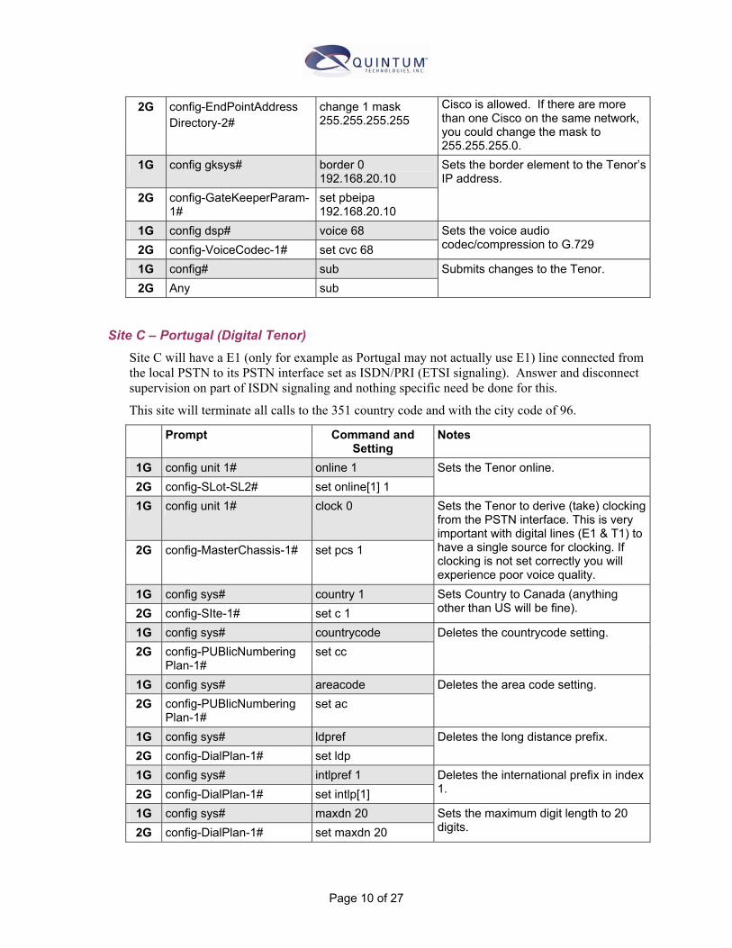
Site C – Portugal (Digital Tenor) Site C will have a E1 (only for example as Portugal may not actually use E1) line connected from the local PSTN to its PSTN interface set as ISDN/PRI (ETSI signaling). Answer and disconnect supervision on part of ISDN signaling and nothing specific need be done for this.
This site will terminate all calls to the 351 country code and with the city code of 96.
Prompt Command and Setting
Notes
1G config unit 1# online 1 2G config-SLot-SL2# set online[1] 1
Sets the Tenor online.
1G config unit 1# clock 0
2G config-MasterChassis-1# set pcs 1
Sets the Tenor to derive (take) clocking from the PSTN interface. This is very important with digital lines (E1 & T1) to have a single source for clocking. If clocking is not set correctly you will experience poor voice quality.
1G config sys# country 1 2G config-SIte-1# set c 1
Sets Country to Canada (anything other than US will be fine).
1G config sys# countrycode 2G config-PUBlicNumbering
Plan-1# set cc
Deletes the countrycode setting.
1G config sys# areacode 2G config-PUBlicNumbering
Plan-1# set ac
Deletes the area code setting.
1G config sys# ldpref 2G config-DialPlan-1# set ldp
Deletes the long distance prefix.
1G config sys# intlpref 1 2G config-DialPlan-1# set intlp[1]
Deletes the international prefix in index 1.
1G config sys# maxdn 20 2G config-DialPlan-1# set maxdn 20
Sets the maximum digit length to 20 digits.
Page 10 of 27
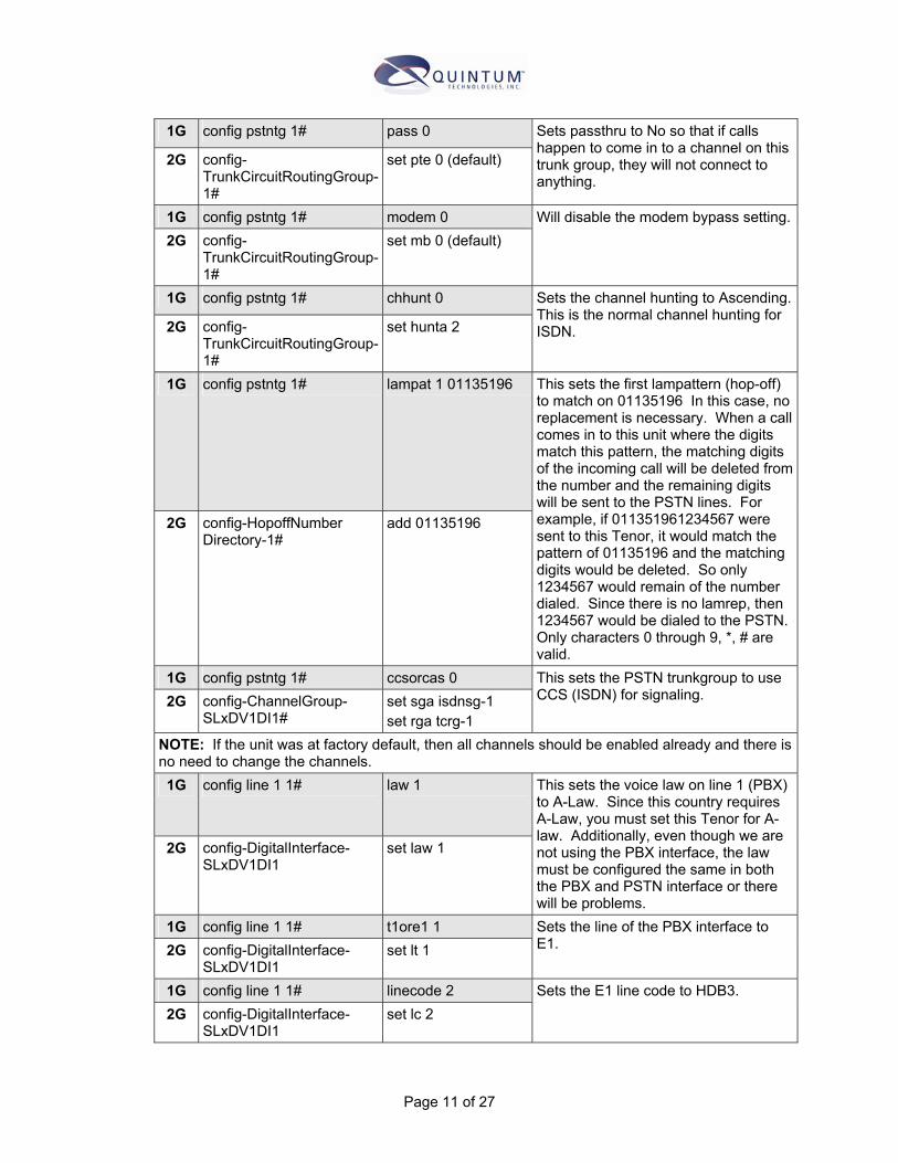
1G config pstntg 1# pass 0
2G config-TrunkCircuitRoutingGroup-1#
set pte 0 (default)
Sets passthru to No so that if calls happen to come in to a channel on this trunk group, they will not connect to anything.
1G config pstntg 1# modem 0 2G config-
TrunkCircuitRoutingGroup-1#
set mb 0 (default) Will disable the modem bypass setting.
1G config pstntg 1# chhunt 0
2G config-TrunkCircuitRoutingGroup-1#
set hunta 2
Sets the channel hunting to Ascending. This is the normal channel hunting for ISDN.
1G config pstntg 1# lampat 1 01135196
2G config-HopoffNumber Directory-1#
add 01135196
This sets the first lampattern (hop-off) to match on 01135196 In this case, no replacement is necessary. When a call comes in to this unit where the digits match this pattern, the matching digits of the incoming call will be deleted from the number and the remaining digits will be sent to the PSTN lines. For example, if 011351961234567 were sent to this Tenor, it would match the pattern of 01135196 and the matching digits would be deleted. So only 1234567 would remain of the number dialed. Since there is no lamrep, then 1234567 would be dialed to the PSTN. Only characters 0 through 9, *, # are valid.
1G config pstntg 1# ccsorcas 0 2G config-ChannelGroup-
SLxDV1DI1# set sga isdnsg-1 set rga tcrg-1
This sets the PSTN trunkgroup to use CCS (ISDN) for signaling.
NOTE: If the unit was at factory default, then all channels should be enabled already and there is no need to change the channels. 1G config line 1 1# law 1
2G config-DigitalInterface-SLxDV1DI1
set law 1
This sets the voice law on line 1 (PBX) to A-Law. Since this country requires A-Law, you must set this Tenor for A-law. Additionally, even though we are not using the PBX interface, the law must be configured the same in both the PBX and PSTN interface or there will be problems.
1G config line 1 1# t1ore1 1 2G config-DigitalInterface-
SLxDV1DI1 set lt 1
Sets the line of the PBX interface to E1.
1G config line 1 1# linecode 2 2G config-DigitalInterface-
SLxDV1DI1 set lc 2
Sets the E1 line code to HDB3.
Page 11 of 27

1G config line 1 1# crc 0 2G config-DigitalInterface-
SLxDV1DI1 set crc 0
Sets the CRC for the E1 to No.
1G config line 1 2# law 1
2G config-DigitalInterface- SLxDV1DI2
set law 1
This sets the voice law on line 2 (PSTN) to A-Law. Since this country requires A-Law, you must set this Tenor for A-law. As indicated above, the law for both line 1 1 and line 1 2 must be the same or you will experience poor voice quality.
1G config line 1 2# t1ore1 1 2G config-DigitalInterface-
SLxDV1DI2 set lt 1
Sets the line of the PSTNinterface to an E1.
1G config line 1 2# linecode 2
2G config-DigitalInterface- SLxDV1DI2
set lc 2
Sets the E1 line code to HDB3. You will need to check with your PSTN provider to verify this setting.
1G config line 1 2# crc 0
2G config-DigitalInterface- SLxDV1DI2
set crc 0
Sets the CRC for the E1 to No. Again, this is a setting that you need to verify with your PSTN provider for this line.
1G config signaling 2# name PSTN_ISDN_01
2G config-ISDNSignalingGroup-1#
isdnsg PSTN_ISDN_01
Enables ISDN signaling group 2 with a name of PSTN_ISDN_01
1G config signaling 2# isdnprot 5
2G config-ISDNSignalingGroup- PSTN_ISDN_01#
set prot 5
Sets the ISDN signaling type to ETSI. Check with your PSTN provider to verify this setting.
1G config signaling 2# orientation 0
2G config-ISDNSignalingGroup- PSTN_ISDN_01#
set or 0 (default)
Sets the orientation of the ISDN on the Tenor to User side. This is typically correct when connected to the PSTN as the PSTN will be network side. If you are connecting to a switch at your location, you may need to check with your switch settings for this as the Tenor should be set opposite of what it is connecting to.
1G config signaling 2# dchnum 16
2G config-ISDNSignalingGroup- PSTN_ISDN_01#
set dch 16
Sets the D-channel (ISDN signaling channel) to channel 16 on the E1. E1s always use channel 16 for the D-channel while T1’s use channel 24 when set for ISDN.
1G config signaling 2# fasunit 1
2G config-ISDNSignalingGroup- PSTN_ISDN_01#
set id 1
Sets the unit id to 1. Anywhere in the Tenor where you see unit, it will always be 1.
1G config signaling 2# fasline 2 Sets the ISDN line to line 2 (PSTN).
Page 12 of 27

2G config-ChannelGroup-SLxDV1DI1#
set sga isdnsg-1 set rga tcrg-1
This allows this signaling group to be associated with the PSTN interface.
NOTE: You may need to go back to the pstntg and enable all the channels now, since changing from T1 to E1 may not add the additional 6 channels. The command to do this is ena 1 a.
1G config gkadmin# allow 1 2G Quintum# epad
Moves to the first allow group for VoIP restrictions based on IP.
1G config gkadmin allow 1# ip 192.168.30.10
2G config-EndPointAddress Directory-1#
add 192.168.30.10 at 1
Configures the first IP/gateway address allowed to this Tenor’s IP address. This must be done if you are going to use the gkadmin area to restrict use by IP. The Tenor’s own IP address must be included in the allow table.
1G config gkadmin allow 1# mask 255.255.255.255
2G config-EndPointAddress Directory-1#
change 1 mask 255.255.255.255
Sets the subnet to 255.255.255.255 so only the IP address of this network is allowed.
1G config gkadmin allow 2# ip 192.168.1.10
2G config-EndPointAddress Directory-2#
add 192.168.1.10 at 1
Sets the 2nd allow group to allow the IP address of the Cisco to send calls to this unit.
1G config gkadmin allow 2# mask 255.255.255.255
2G config-EndPointAddress Directory-2#
change 1 mask 255.255.255.255
Sets the subnet to 255.255.255.255 so that only the IP address of that one Cisco is allowed. If there are more than one Cisco on the same network, you could change the mask to 255.255.255.0.
1G config gksys# border 0 192.168.30.10
2G config-GateKeeperParam-1#
set pbeipa 192.168.30.10
Sets the border element to the Tenor’s IP address.
1G config dsp# voice 68 2G config-VoiceCodec-1# set cvc 68
Sets the voice audio codec/compression to G.729
1G config# sub 2G Any sub
Submits changes
NOTE: Since the law was changed from U-law to A-law, you will need to reset the Tenor AFTER you have submitted the changes.
Page 13 of 27

Cisco Dial Peer Examples The following dial peer examples are based on information from existing Quintum customers who are using Cisco to originate traffic to Tenors as the above examples show. Quintum cannot configure a customer’s Cisco equipment and we can not guarantee that the dial peers listed below will work in all occasions. As always, you should verify these settings with Cisco.
Dial Peer to Site A – Romania The following sample dial peer will allow any calls that begin with 01140232 + 6 digits to be sent to 192.168.10.10 with a codec of G.729.
dial-peer voice 300 voip destination-pattern 01140232...... session target ipv4:192.168.10.10 codec g729r8 bytes 30
Dial Peer to Site B – Egypt The following sample dial peer will allow any calls that begin with 01120 + any number of digits, to be sent to 192.168.20.10 with a codec of G.729
dial-peer voice 301 voip destination-pattern 01120T session target ipv4:192.168.20.10 codec g729r8 bytes 30
Dial Peer to Site C – Portugal The following sample dial peer will allow any calls that begin with 01135196 + any digits to be sent to 192.168.30.10 with a codec of G.729.
dial-peer voice 300 voip destination-pattern 01135196T. session target ipv4:192.168.30.10 codec g729r8 bytes 30
Cisco GW > Tenor GW Summary Using the configuration above as an example, you should find it relatively easy to configure the Tenor to receive a call from a Cisco and terminate it to the local PSTN lines.
Page 14 of 27

Tenor Terminating Calls to Cisco Gateway
Figure 2
Application Description As shown in Figure 2 above, this application will have a Cisco Gateway in New York that will receive traffic from IP (from Tenors) in Morocco and Taiwan.
• 1G: The Tenor in Morocco is a digital Tenor with an E1 connection (ISDN) and the Tenor in Taiwan is an A400 with 4 lines from the local PSTN.
• 2G: The Tenor in Morocco is a Tenor DX with an E1 connection (ISDN) and the Tenor in Taiwan is a Tenor AX with 4 lines from the local PSTN.
In Morocco, calls will come in to the Digital Tenor with the digits of 001xxxxxxxxxx2 and we will pass these digits over IP to the Cisco (001xxxxxxx).
For Taiwan, we will use 2nd dialtone and simple Pincode verification to allow incoming calls from the PSTN to get a dial tone and then dial 1xxxxxxxxxx. The Tenor will then need to add 00 to the front of the number to send the call to the Cisco.
An audio codec of G.729 will be used for this application.
The Tenors will be configured not to accept any calls from IP for this application.
Unfortunately, Quintum does not have a sample Cisco dial peer to address this application. Please contact Cisco to get the correct parameters on this.
2 Sending the international prefix, or any non-E164 digit/character, is a violation of the H.323 specification. The Tenor can address this in most cases. See Appendix for more information on the E.164 format as it relates to H.323.
Page 15 of 27

Tenor Configuration and Notes The following configuration information takes into consideration that the Tenor is at factory default with no previous configuration loaded. Only the IP address, subnet mask and default gateway are configured.
All configuration will be done from the Command Line Interface (CLI).
Not all configuration items are shown. Only those necessary to this application will be shown. Additionally, if a command is shown with out any parameter, this means to enter the command only so that any pre-configured setting will be deleted. For example, entering the command “areacode” without any parameters will delete the set area code.
Finally, the following configurations are laid out so that an engineer/technician that has experience with configuring Tenors will be able to understand this. If you have no experience with configuring Tenors from the Command Line Interface, we suggest you contact the QTAC for support.
Site A – Morocco (Digital Tenor) Site A will have an E1 line connected from the local PSTN to its PSTN interface set as ISDN/PRI (ETSI signaling). Answer and disconnect supervision on part of ISDN signaling and nothing specific need be done for this.
This site will receive calls from this E1 line that will have the digits 001xxxxxxxxxx and these calls will need to be forwarded to the Cisco in New York with the 001 digits.
Prompt Command and Setting
Notes
1G config unit 1# online 1 2G config-SLot-SL2 set online[1] 1
Sets the Tenor online.
1G config unit 1# clock 0
2G config-MasterChassis-1# set pcs 1
Sets the Tenor to derive (take) clocking from the PSTN interface. This is very important with digital lines (E1 & T1) to have a single source for clocking. If clocking is not set correctly you will experience poor voice quality.
1G config sys# country 1 2G config-SIte-1# set c 1
Sets Country to Canada (anything other than US will be fine).
1G config sys# countrycode 2G config-PUBlicNumbering
Plan-1# set cc
Deletes the countrycode setting.
1G config sys# areacode 2G config-PUBlicNumbering
Plan-1# set ac
Deletes the area code setting.
1G config sys# ldpref 2G config-DialPlan-1# set ldp
Deletes the long distance prefix.
1G config sys# intlpref 1 2G config-DialPlan-1# set intlp[1]
Deletes the international prefix in index 1.
1G config sys# maxdn 20 Sets the maximum digit length to 20
Page 16 of 27

2G config-DialPlan-1# set maxdn 20 digits.
1G config pstntg 1# pass 0
2G config-TrunkCircuitRoutingGroup-1#
set pte 0 (default)
Sets passthru to No so that incoming calls will be routed over IP. If this was set to 1 (for Yes), then all incoming calls would be unconditionally routed to the PBX trunk group.
1G config pstntg 1# modem 0 2G config-
TrunkCircuitRoutingGroup-1#
set mb 0 (default) Will disable the modem bypass setting.
1G config pstntg 1# chhunt 0 2G config-
TrunkCircuitRoutingGroup-1#
set hunta 2 Sets the channel hunting to Ascending. This is the normal channel hunting for ISDN.
1G config pstntg 1# direction 0 2G config-
TrunkCircuitRoutingGroup-1#
set dir 0 Sets the call direction to incoming only on this trunk group. It will not allow any outgoing calls.
1G config pstntg 1# ccsorcas 0 2G config-ChannelGroup-
SLxDV1DI1# set sga isdnsg-1 set rga tcrg-1
This sets the PSTN trunkgroup to use CCS (ISDN) for signaling.
NOTE: If the unit was at factory default, then all channels should be enabled already and no need to change the channels. 1G config line 1 1# law 1 2G config-DigitalInterface-
SLxDV1DI1 set law 1
This sets the voice law on line 1 (PBX) to A-Law. Since this country requires A-Law, you must set this Tenor for A-law. Additionally, even though we are not using the PBX interface, the law must be configured the same in both the PBX and PSTN interface or there will be problems.
1G config line 1 1# t1ore1 1 2G config-DigitalInterface-
SLxDV1DI1 set lt 1
Sets the line of the PXB interface to an E1.
1G config line 1 1# linecode 2 2G config-DigitalInterface-
SLxDV1DI1 set lc 2
Sets the E1 line code to HDB3.
1G config line 1 1# crc 0 2G config-DigitalInterface-
SLxDV1DI1 set crc 0
Sets the CRC for the E1 to No.
1G config line 1 2# law 1 2G config-DigitalInterface-
SLxDV1DI2 set law 1
This sets the voice law on line 2 (PSTN) to A-Law. Since this country requires A-Law, you must set this Tenor for A-law. As indicated above, the law for both line 1 1 and line 1 2 must be the same or you will experience poor voice quality.
1G config line 1 2# t1ore1 1 Sets the line of the PSTNinterface to an
Page 17 of 27

2G config-DigitalInterface- SLxDV1DI2
set lt 1 E1.
1G config line 1 2# linecode 2
2G config-DigitalInterface- SLxDV1DI2
set lc 2
Sets the E1 line code to HDB3. You will need to check with your PSTN provider to verify this setting.
1G config line 1 2# crc 0
2G config-DigitalInterface- SLxDV1DI2
set crc 0
Sets the CRC for the E1 to No. Again, this is a setting that you need to verify with your PSTN provider for this line.
1G config signaling 2# name PSTN_ISDN_01
2G config-ISDNSignalingGroup-1#
isdnsg PSTN_ISDN_01
Enables ISDN signaling group 2 with a name of PSTN_ISDN_01
1G config signaling 2# isdnprot 5
2G config-ISDNSignalingGroup- PSTN_ISDN_01#
set prot 5
Sets the ISDN signaling type to ETSI. Check with your PSTN provider to verify this setting.
1G config signaling 2# orientation 0 2G config-
ISDNSignalingGroup- PSTN_ISDN_01#
set or 0 (default) Sets the orientation of the ISDN on the Tenor to User side. This is typically correct when connected to the PSTN as the PSTN will be network side. If you are connecting to a switch at your location, you may need to check with your switch settings for this as the Tenor should be set opposite of what it is connecting to.
1G config signaling 2# dchnum 16 2G config-
ISDNSignalingGroup- PSTN_ISDN_01#
set dch 16 Sets the D-channel (ISDN signaling channel) to channel 16 on the E1. E1s always use channel 16 for the D-channel while T1’s use channel 24 when set for ISDN.
1G config signaling 2# fasunit 1
2G config-ISDNSignalingGroup- PSTN_ISDN_01#
set id 1
Sets the unit id to 1. Anywhere in the Tenor where you see unit, it will always be 1.
1G config signaling 2# fasline 2 2G config-ChannelGroup-
SLxDV1DI1# set sga isdnsg-1 set rga tcrg-1
Sets the ISDN line to line 2 (PSTN). This allows this signaling group to be associated with the PSTN interface.
NOTE: You may need to go back to the pstntg and enable all the channels now, since changing from T1 to E1 may not add the additional 6 channels. The command to do this is ena 1 a. 1G config gksys# border 0
192.168.10.10 2G config-GateKeeperParam-
1# set pbeipa 192.168.10.10
Sets the border element to the Tenor’s IP address.
1G config dsp# voice 68 2G config-VoiceCodec-1# set cvc 68
Sets the voice audio codec/compression to G.729
Page 18 of 27
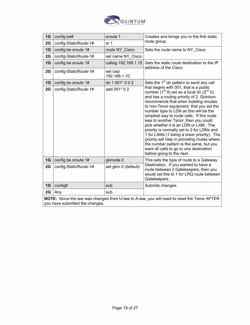
1G config be# sroute 1 2G config-StaticRoute-1# sr 1
Creates and brings you to the first static route group.
1G config be sroute 1# route NY_Cisco 2G config-StaticRoute-1# set name NY_Cisco
Sets the route name to NY_Cisco
1G config be sroute 1# callsig 192.168.1.10
2G config-StaticRoute-1# set csip 192.168.1.10
Sets the static route destination to the IP address of the Cisco.
1G config be sroute 1# dn 1 001* 0 0 2 2G config-StaticRoute-1# add 001* 0 2
Sets the 1st dn pattern to send any call that begins with 001, that is a public number (1st 0) set as a local dn (2nd 0) and has a routing priority of 2. Quintum recommends that when building sroutes to non-Tenor equipment, that you set the number type to LDN as this will be the simplest way to route calls. If this route was to another Tenor, then you could pick whether it is an LDN or LAM. The priority is normally set to 2 for LDNs and 1 for LAMs (1 being a lower priority). The priority will help in providing routes where the number pattern is the same, but you want all calls to go to one destination before going to the next.
1G config be sroute 1# gkmode 0 2G config-StaticRoute-1# set gkm 0 (default)
This sets the type of route to a Gateway Destination. If you wanted to have a route between 2 Gatekeepers, then you would set this to 1 for LRQ route between Gatekeepers.
1G config# sub 2G Any sub
Submits changes.
NOTE: Since the law was changed from U-law to A-law, you will need to reset the Tenor AFTER you have submitted the changes.
Page 19 of 27

Site B – Taiwan (Analog Tenor) Site B will have 4 analog lines connected from the local PSTN to its PSTN interface. Calls will come in to the Tenor from the PSTN, get a “beep” tone to enter a 8 digit pin that must begin with 8345 and then receive 2nd dialtone and then dial 1xxxxxxxxxx. The Tenor will then add 00 to the front of the number and send 001xxxxxxxxxx to the Cisco in NY.
Prompt Command and Setting
Notes
1G config unit 1# online 1 2G config-SLot-SL2# set online[1] 1
Sets the Tenor online.
1G config sys# country 1 2G config-SIte-1# set c 1
Sets Country to Canada (anything other than US will be fine).
1G config sys# countrycode 2G config-PUBlicNumbering
Plan-1# set cc
Deletes the countrycode setting.
1G config sys# areacode 2G config-PUBlicNumbering
Plan-1# set ac
Deletes the area code setting.
1G config sys# ldpref 2G config-DialPlan-1# set ldp
Deletes the long distance prefix.
1G config sys# intlpref 1 2G config-DialPlan-1# set intlp[1]
Deletes the international prefix in index 1.
1G config sys# maxdn 20 2G config-DialPlan-1# set maxdn 20
Sets the maximum digit length to 20 digits.
1G config pstntg 1# pass 0
2G config-TrunkCircuitRoutingGroup-1#
set pte 0 (default)
Sets passthru to No so that incoming calls will be routed over IP. If this was set to 1 (for Yes), then all incoming calls would be unconditionally routed to the PBX trunk group.
1G config pstntg 1# modem 0 2G config-
TrunkCircuitRoutingGroup-1#
set mb 0 (default) Will disable the modem bypass setting.
1G config pstntg 1# chhunt 2
2G config-TrunkCircuitRoutingGroup-1#
set hunta 2
Sets the channel hunting to Ascending Round-Robin. This is useful on analog so that the calls will hunt in a round-robin fashion. This way if there is one line that is failing, it will only be attempted 1 out of 4 times (or 8 if this were an A800). See the CLI guide on this command for more information.
1G config pstntg 1# dir 0 2G config-
TrunkCircuitRoutingGroup-1#
set dir 0 Sets the call direction to incoming only on this trunk group. It will not allow any outgoing calls.
Page 20 of 27

1G config pstntg 1# ivrtype 1 2G config-
TrunkCircuitRoutingGroup-1#
set ivrt 1 Sets the IVRtype to 2nd dialtone. This will provide a 2nd dialtone to incoming calls.
1G config pstntg 1# pin 8345xxxx
2G config-TrunkCircuitRoutingGroup-1#
set pin 8345xxxx
This sets the pincode for the 2nd dialtone to any 8 digit number beginning with 8345. When a user dials in to the PSTN interface, they will hear a beep tone. When they here this they must enter the correct pin code. If they enter a wrong pincode, they will hear a busy signal and get disconnected.
1G config pstntg 1# cassig 6
2G config-CASSignalingGroup-1#
set st 3
This sets the signaling to Loop Start with forward disconnect. With this setting, the Tenor will recognize the removal of battery that is sent by the PSTN to indicate that the call is disconnected. The PSTN must support this type of disconnect supervision.
NOTE: If the unit was at factory default, then all channels should be enabled already and there is no need to change the channels. 1G config gksys# border 0
192.168.20.10 2G config-GateKeeperParam-
1# set pbeipa 192.168.20.10
Sets the border element to the Tenor’s IP address.
1G config dsp# voice 68 2G config-VoiceCodec-1# set cvc 68
Sets the voice audio codec/compression to G.729
1G config iptg# outpref 00
2G config-IPDialPlan-1# set outp 00
This will add the digits 00 to the front of all dialed numbers going to IP. This will also change the number from public to private for routing purposes and we must address this in the routing configuration.
1G config be sroute 1# route NY_Cisco 2G config-StaticRoute-1# set name NY_Cisco
Sets the route name to NY_Cisco
1G config be sroute 1# callsig 192.168.1.10
2G config-StaticRoute-1# set csip 192.168.1.10
Sets the static route destination to the IP address of the Cisco.
1G config be sroute 1# dn 1 001* 0 0 2 Sets the 1st dn pattern to send any call that begins with 001, hat is a public number (1st 0) set as a local dn (2nd 0) and has a routing priority of 2. Quintum recommends that when building sroutes to non-Tenor equipment, that you set the number type to LDN as this will be the
Page 21 of 27
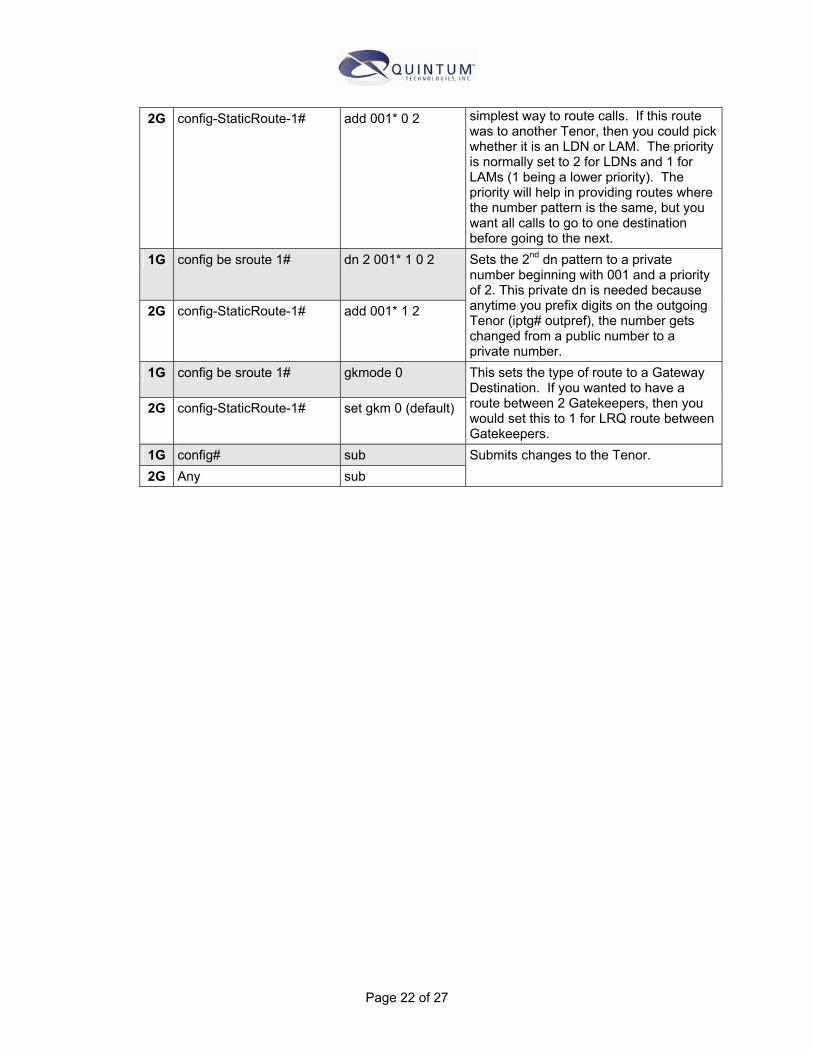
2G config-StaticRoute-1# add 001* 0 2 simplest way to route calls. If this route was to another Tenor, then you could pick whether it is an LDN or LAM. The priority is normally set to 2 for LDNs and 1 for LAMs (1 being a lower priority). The priority will help in providing routes where the number pattern is the same, but you want all calls to go to one destination before going to the next.
1G config be sroute 1# dn 2 001* 1 0 2
2G config-StaticRoute-1# add 001* 1 2
Sets the 2nd dn pattern to a private number beginning with 001 and a priority of 2. This private dn is needed because anytime you prefix digits on the outgoing Tenor (iptg# outpref), the number gets changed from a public number to a private number.
1G config be sroute 1# gkmode 0
2G config-StaticRoute-1# set gkm 0 (default)
This sets the type of route to a Gateway Destination. If you wanted to have a route between 2 Gatekeepers, then you would set this to 1 for LRQ route between Gatekeepers.
1G config# sub 2G Any sub
Submits changes to the Tenor.
Page 22 of 27

Summary The above applications/configuration do provide some standard examples to be able to originate and terminate calls to/from Cisco when using a Quintum Tenor. There are many other ways that this could be done, but this will provide you information to get you started.
As always, if you require additional information, please contact your Quintum VAR or Quintum Technical Assistance Center.
Page 23 of 27

Appendix Extract of Appendix V of the ITU-T H.323 Version 4 Draft (11/2000) Use of E.164 and ISO/IEC 11571 Numbering Plans
V.1 E.164 Numbering plan ITU-T Recommendation defines E.164 numbers the following way for geographic areas:
Figure V.1/H.323 - International public telecommunication number structure for geographic areas
Similar descriptions are also defined for non-geographic areas. Recommendation E.164 further defines country codes (CC) for all the countries and regions of the world.
An international E.164 number always starts with a country code and its total length is always 15 digits or less. More importantly, it does not include any prefixes that are part of a dialing plan (for example, “011 for an international call placed in North America, or “1” for a long-distance call), nor does it include “#” or “*”. The number “49 30 345 67 00” is a n E.164 number with CC=49 for Germany. A national number is the international number stripped of the country code, “30 345 67 00” in this case. The subscriber number is the national number stripped of the national destination code, “345 67 00” in this case.
An E.164 number has global significance: E.164 number can be reached from any location in the world. A “dialed digit sequence”, however, only has significance within a specific domain. Within a typical private numbering plan in an enterprise, for example, a prefix, such as “9”, may indicate that a call goes “outside”, at which point the local telephone company’s dialing plan takes over. Each telephone company or private network is free to choose its own dialing plan. It is also free to change it as it pleases – an frequently does so (adding new area codes, for example).
In a typical geographically determined network where user input telephone numbers manually and where user do not travel too much, having different dialing plans everywhere is usually a problem. However, when a user travels, the user must determine the other network’s numbering plan in order to place calls. When computer systems perform the dialing automatically, the user is usually required to customize the dialing software for every region or network.
Because of these issues with varying dialing plans and automated dialing, it is essential to be able to refer to an absolute “telephone number” instead of “what you have to dial to reach it from a specific location.” Proper usage of E.164 numbers can resolve these issues. Many systems use E.164 numbers instead of dialed digits: for example, a PBX may gather the dialed digits from a
Page 24 of 27

user on a telephone and then initiate a call to the local phone company using an E.164 number in the Called Party Number information element in Q.931. When completing the Called Party Number IE< specifying the numbering plan as “ISDN/telephony numbering plan (Recommendation E.164)” indicates an E.164 number. Specifying the type of number as “unknown” and specifying the numbering plan as “unknown” indicates dialed digits.
The following are a set of definitions from E.164.
Number A string of decimal digits that uniquely indicates the public network termination point. The number contains the information necessary to route the call to this termination point.
A number can be in a format determined nationally or in an international format. The international format is known as the International Public Telecommunication Number which includes the country code and subsequent digits, but no the international prefix.
Numbering plan A numbering plan specifies the format and structure of the numbers used within that plan. It typically consists of decimal digits segmented into groups in order to identify specific elements used for identification, routing and charging capabilities, e.g. within E.164 to identify countries, national destinations, and subscribers.
A numbering plan does not include prefixes, suffixes, and additional information required to complete a call.
The national numbering plan is the national implementation of the E.164 numbering plan.
Dialing plan A string or combination of decimal digits, symbols, and additional information that define the method by which the numbering plan is used. A dialing plan includes the use of prefixes, suffixes, and additional information, supplemental to the numbering plan, required to complete the call.
Address A string or combination of decimal digits, symbols, and additional information which identifies the specific termination point(s) of a connection in a public network(s) or, where applicable, in interconnected private network(s).
Prefix A prefix is an indicator consisting of one or more digits, that allows the selection of different types of number formats, networks and/or service.
International prefix A digit or combination of digits used to indicate that the number following is an International Public Telecommunication Number.
Country code (CC) for geographic areas The combination of one, two or three digits identifying a specific country, countries in an integrated number plan, or a specific geographic area.
Page 25 of 27

National (significant) number [N(S)N] That portion of the number that follows the country code for geographic areas. The national (significant) number consists of the National Destination Code (NDC) followed by the Subscriber Number (SN). The function and format of the N(S)N is nationally determined.
National destination code (NDC) A nationally optional code field, within the E.164 numbering plan, which combined with the Subscriber’s Number (SN) will constitute the national (significant) number of the international public telecommunication number for geographic areas. The NDC will have a network and/or trunk code selection function.
The NDC can be a decimal digit or a combination of decimal digits (not including any prefix) identifying a numbering area within a country (or group of countries included in one integrated numbering plan or a specific geographic area) and/or network/services.
National (trunk) prefix A digit or combination of digits used by a calling subscriber, making a call to a subscriber in his own country but outside his own numbering area. It provides access to the automatic outgoing trunk equipment.
Subscriber number (SN) The number identifying a subscriber in a network or numbering area.
V.2 Private Network Number Private Network Numbers are used in a private or virtual private telephony networks, e.g., a corporate network of PBXs and virtual private lines.
ISO/IEC 11571 defines Private Network Number (PNP) as having up to three regional levels.
A PNP number shall comprise a sequence of x decimal digits (0,1,2,3,4,5,6,7,8,9) with the possibility that different PNP numbers within the same PNP can have different values of x. Then maximum value of x shall be the same as for the public ISDN numbering plan, see ITU-T Recommendation E.164.
Level 2 Regional Number Level 1 Regional Number Level 0 Regional Number
Figure V.2/H.323 – Structure of a PNP number with three levels of regions
A level n Regional Number (RN) shall have significance only within the level n region to which it applies. When that number is used outside that level n region, it shall be in the form of an RN of level greater than n. Only a Complete Number shall have significance throughout the entire PNP.
A typical example in North America would be a 4-digit “extension” as the Level 0 Regional Number: a 3-digit “location code” combined with the 4 digit “extension” would form the Level 1 Regional Number. The Level 2 Regional Number would be nil.
A prefix could also be used to signal which regional number is used, and would not be part of the regional number per se, but only part of the dialing plan. Again, a typical example would be the
Page 26 of 27

Page 27 of 27
use of digit “6” to access a Level 1 Regional Number, and no digit for a Level 0 Regional Number.
The following are a set of definitions from ISO/IEC 11571:
Private Numbering Plan (PNP) The numbering plan explicitly relating to a particular private numbering domain, defined by the PISN Administrator of that domain.
Region The entire domain or a sub-domain of a PNP. A region does not necessarily correspond to a geographical area of PISN.
Regional Number (RN) A particular form of a PNP Number which is unambiguous in the region concerned.
Complete Number A number which is unambiguous in the entire PNP, i.e. which corresponds to the highest regional level employed in that PISN.
V.3 H.323 version 1, 2 and 3 usage H.323 version 1, 2 and 3 systems had a terminology problem with respect to dialed digits and real E.164 numbers. References to E.164 addresses in those version actually referred to dialed digits and not E.164 digits, as the names of the fields implied. In H.323 versions 2 and 3 systems, a real E.164 number was placed in the publicNumber field and not in the e164 field. The e164 field thus corresponded to a dialed digits sequence.
Beginning with H.323 Version 4 systems, the field e164 was renamed to dialedDigits and the field publicNumber was renamed to e164Number. The name change was intended to more explicitly convey that dialed digits shall be stored in the dialedDigits field and the E.164 numbers shall be stored in the e164Number field.