ciscotelepresence videocommunication...
TRANSCRIPT

Cisco TelePresenceVideo Communication
Server Basic Configuration(Single VCS Control)
Deployment Guide
Cisco VCS X7.2
D14524.03
August 2012

Cisco VCS Basic Configuration (Single VCS Control) Deployment Guide Page 2 of 32
Contents
Introduction 3Example network deployment 3Internal network elements 4
SIP and H.323 domain 4
Prerequisites and process summary 5Prerequisites 5Summary of process 5
Cisco VCS system configuration 6Step 1: Initial configuration 6Step 2: System name configuration 7Step 3: DNS configuration 8
Local host name 8Domain name 8DNS servers 8
Step 4: Time configuration 10Step 5: SIP domain configuration 11
Routing configuration 12Pre-search transforms 12Search rules 12Step 6: Transform configuration 13Step 7: Local zone search rules configuration 14
Endpoint registration 17
System checks 18Registration status 18Call signaling 18
Maintenance routine 19System backup 19
Optional configuration steps 20Cisco TMS configuration (optional) 20Logging server configuration (optional) 22Registration restriction configuration (optional) 23Restrict access to ISDN gateways (optional) 24
Appendix 1 – Configuration details 27
Appendix 2 – DNS records configuration 29Local DNS A record 29Local DNS SRV records 29
Checking for updates and getting help 30
Document revision history 31
Disclaimer 31

Introduction
Cisco VCS Basic Configuration (Single VCS Control) Deployment Guide Page 3 of 32
IntroductionThe Cisco TelePresence Video Communication Server (VCS) can be deployed as a VCS Control applicationor as a VCS Expressway™ application.
The VCS Expressway enables business to business communications, empowers remote and home basedworkers, and gives service providers the ability to provide video communications to customers. The VCSControl provides SIP proxy and call control as well as H.323 gatekeeper services within an organization'scorporate network environment.
This document describes how to configure a single Cisco VCSControl platform for use in a basic videoinfrastructure deployment. If your deployment includes a Cisco VCSExpressway, useCisco VCS BasicConfiguration (Control with Expressway) Deployment Guide instead.
Detailed reference information is contained in this document’s appendices:
n Appendix 1 lists the configuration details used to configure the VCSs in the example network deployment.n Appendix 2 includes details of the DNS records required for the system deployment to work as expected.
Descriptions of system configuration parameters can be found in theVCS Administrator Guide and the VCSweb application’s online field help and page help .
This document does not describe details of how to deploy a cluster of VCSs, or VCSs running DeviceProvisioning or FindMe applications. For more details on these features, see the following documents:
n VCS Cluster Creation andMaintenance Deployment Guiden Cisco TMS Provisioning Extension Deployment Guiden FindMe Express Deployment Guide
These documents can be found at: http://www.cisco.com/cisco/web/support/index.html
Example network deploymentThe example network shown below is used as the basis for the deployment configuration described in thisdocument.
Figure 1: Example network deployment

Introduction
Cisco VCS Basic Configuration (Single VCS Control) Deployment Guide Page 4 of 32
Internal network elementsThe internal network elements are devices which are hosted on the organization’s local area network.
Elements on the internal network have an internal network domain name. This internal network domain nameis not resolvable by a public DNS. For example, the VCS Control is configured with an internally resolvablename of vcsc.internal-domain.net (which resolves to an IP address of 10.0.0.2 by the internal DNS servers).
VCS Control
The VCS Control is a SIP Registrar & Proxy and H.323Gatekeeper for devices which are located on theinternal network.
E20 and MXP1700
These are example endpoints hosted on the internal network which register to the VCS Control.
DNS (local 1 & local 2)
DNS servers used by the VCS Control, to perform DNS lookups (resolve network names on the internalnetwork).
DHCP server
The DHCP server provides host, IP gateway, DNS server, and NTP server addresses to endpoints locatedon the internal network.
Syslog server
A logging server for Syslogmessages (see Logging server configuration (optional) [p.22]).
Cisco TMS server
A management and scheduling server (see Cisco TMS configuration (optional) [p.20]).
NTP server
AnNTP server which provides the clock source used to synchronize devices.
SIP and H.323 domainThe example deployment is configured to route SIP (and H.323) signalingmessages for calls made to URIswhich use the domain example.com.
The DNS SRV configurations are described in Appendix 2 – DNS records configuration [p.29].
Prerequisites and process summary
Cisco VCS Basic Configuration (Single VCS Control) Deployment Guide Page 5 of 32
Prerequisites and process summary
PrerequisitesBefore starting the system configuration, make sure you have access to:
n theVCS Administrator Guide andVCS Getting Started Guide (for reference purposes)n a VCS Control running version X5 or latern a PC connected via Ethernet to a LAN which can route HTTP(S) traffic to the VCSn a web browser running on the PCn a serial interface on the PC and cable (if the initial configuration is to be performed over the serial interface)
Summary of processThe configuration process consists of the following steps.
VCS system configuration:
n Step 1: Initial configuration [p.6]n Step 2: System name configuration [p.7]n Step 3: DNS configuration [p.8]n Step 4: Time configuration [p.10]n Step 5: SIP domain configuration [p.11]
Routing configuration:
n Step 6: Transform configuration [p.13]n Step 7: Local zone search rules configuration [p.14]
Optional configuration steps:
n Cisco TMS configuration (optional) [p.20]n Logging server configuration (optional) [p.22]n Registration restriction configuration (optional) [p.23]n Restrict access to ISDN gateways (optional) [p.24]

Cisco VCS system configuration
Cisco VCS Basic Configuration (Single VCS Control) Deployment Guide Page 6 of 32
Cisco VCS system configuration
Step 1: Initial configurationAssuming the VCS is in the factory delivered state, follow the Initial configuration steps described in theVideo Communications Server Getting Started Guide to configure the VCS basic network parameters:
n LAN1 IP (IPv4 or IPv6) addressn Subnet mask (if using IPv4)n Default Gateway IP address (IPv4 or IPv6)
Note that VCSs require static IP addresses (they will not pick up an IP address from aDHCP server).
The initial configuration can be performed in one of three ways:
n using a serial cablen via the front panel of the VCSn via the default IP address of 192.168.0.100
See the “Initial configuration” section inVCS Getting Started Guide for details.
This deployment guide is based on configuration using the web interface. If you cannot access the VCSusing the web interface after completing the initial configuration (assigning the IP address), speak to yournetwork administrator.
The follow configuration values are used in the example deployment:
LAN1 IPv4 address 10.0.0.2
IPv4 gateway 10.0.0.1
LAN1 subnet mask 255.255.255.0

Cisco VCS system configuration
Cisco VCS Basic Configuration (Single VCS Control) Deployment Guide Page 7 of 32
Step 2: System name configurationTheSystem name defines the name of the VCS.
TheSystem name appears in various places in the web interface, and in the display on the front panel of theunit (so that you can identify it when it is in a rack with other systems). The system name is also used byCisco TMS.
You are recommended to give the VCS a name that allows you to easily and uniquely identify it. If the systemname is longer than 16 characters, only the last 16 characters will be shown in the display on the front panel.
To configure theSystem name:
1. Go to theSystem administration page (System > System).2. Configure theSystem name as follows:
System name Enter VCSc
3. Click Save.

Cisco VCS system configuration
Cisco VCS Basic Configuration (Single VCS Control) Deployment Guide Page 8 of 32
Step 3: DNS configuration
Local host nameThe Local host name defines the DNS hostname that this system is known by. Note that this is not thefully-qualified domain name, just the host label portion.
Note that <Local host name>.<Domain name> = FQDN of this VCS.
To configure the Local host name:
1. Go to theDNS page (System > DNS).2. Configure the Local host name as follows:
Local host name Enter vcsc
3. Click Save.
Domain nameTheDomain name is the name to append to an unqualified host name before querying the DNS server.
To configure theDomain name:
1. Go to theDNS page (System > DNS).2. Configure theDomain name as follows:
Domain name Enter internal-domain.net
3. Click Save.
DNS serversThe DNS server addresses are the IP addresses of up to 5 domain name servers to use when resolvingdomain names. Youmust specify at least one default DNS server to be queried for address resolution if youwant to either:
n use FQDNs (Fully Qualified Domain Names) instead of IP addresses when specifying external addresses(for example for LDAP and NTP servers, neighbor zones and peers)
n use features such as URI dialing or ENUM dialing
The VCS only queries one server at a time; if that server is not available the VCS will try another server fromthe list.
In the example deployment 2 DNS servers are configured for each VCS, which provides a level of DNSserver redundancy. The VCS Control is configured with DNS servers which are located on the internalnetwork.
To configure theDefault DNS server addresses:
1. Go to theDNS page (System > DNS).2. Configure the DNS serverAddress fields as follows:

Cisco VCS system configuration
Cisco VCS Basic Configuration (Single VCS Control) Deployment Guide Page 9 of 32
Address 1 Enter 10.0.0.11
Address 2 Enter 10.0.0.12
3. Click Save.
Cisco VCS system configuration
Cisco VCS Basic Configuration (Single VCS Control) Deployment Guide Page 10 of 32
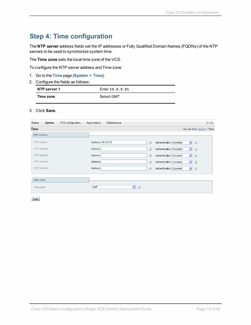
Step 4: Time configurationTheNTP server address fields set the IP addresses or Fully Qualified Domain Names (FQDNs) of the NTPservers to be used to synchronize system time.
The Time zone sets the local time zone of the VCS.
To configure the NTP server address and Time zone:
1. Go to the Time page (System > Time).2. Configure the fields as follows:
NTP server 1 Enter 10.0.0.21
Time zone SelectGMT
3. Click Save.

Cisco VCS system configuration
Cisco VCS Basic Configuration (Single VCS Control) Deployment Guide Page 11 of 32
Step 5: SIP domain configurationThe VCS acts as a SIP Registrar for configured SIP domains, accepting registration requests for any SIPendpoints attempting to register with an alias that includes these domains.
n Registration restriction (Allow or Deny) rules can be configured to limit acceptable registrations. SeeRegistration restriction configuration (optional) [p.23].
n If authentication is enabled, only devices that can properly authenticate themselves will be allowed toregister.
To configure a SIP domain:
1. Go to theDomains page (VCS configuration > Protocols > SIP > Domains).2. Click New.3. Enter the domain name into theName field:
Name Enter example.com
4. Click Create domain.5. TheDomains page displays all configured SIP domain names.

Routing configuration
Cisco VCS Basic Configuration (Single VCS Control) Deployment Guide Page 12 of 32
Routing configuration
Pre-search transformsPre-search transform configuration allows the destination alias (called address) in an incoming searchrequest to bemodified. The transformation is applied by the VCS before any searches take place, eitherlocally or to external zones.
The pre-search transform configuration described in this document is used to standardize destination aliasesoriginating from both H.323 and SIP devices.
For example, if the called address is an H.323 E.164 alias “01234” the VCS will automatically append theconfigured domain name (in this case example.com) to the called address (that is, [email protected] it into a URI), before attempting to set up the call.
This is carried out to make the call searches the same for calls from H.323 endpoints and SIP endpoints.
n Pre-search transforms should be used with care because they apply to all signalingmessages – if theymatch, they will affect the routing of provisioning and presence requests as well as call requests.
n Transformations can also be carried out in search rules – consider whether it is best to use a pre-searchtransform or a search rule to modify the called address to be looked up.
Search rulesThe search rules configuration defines how the VCS routes calls (to destination zones) in specific callscenarios. When a search rule is matched, the destination alias can bemodified according to the conditionsdefined in the search rule.
The search rules configuration described in this document is used to ensure SIP (and H.323) endpoints candial H.323 devices that have registered E.164 numbers or H.323 IDs without a domain portion. The searchrules first search for received destination aliases without the domain portion of the URI, and then searchingwith the full URI.
The routing configuration in this document searches for destination aliases that have valid SIP URIs (that is,using a valid SIP domain, such as id@domain).
It is possible to configure routing which enables calls to unregistered devices on an internal network (routingto the addresses of IP of the devices) by configuring a search rule with mode of Any IP address with targetLocal Zone. However this is not recommended (and not described in this document). The best practice is toregister all devices and route using destination aliases.
Routing configuration
Cisco VCS Basic Configuration (Single VCS Control) Deployment Guide Page 13 of 32
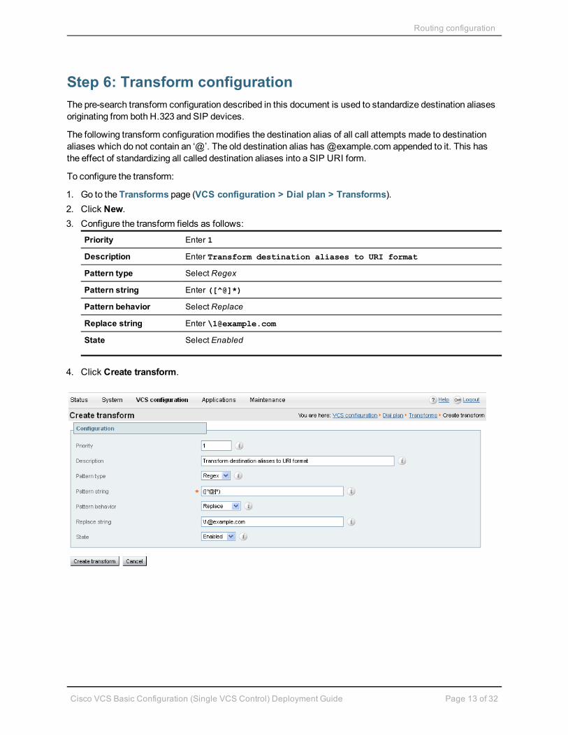
Step 6: Transform configurationThe pre-search transform configuration described in this document is used to standardize destination aliasesoriginating from both H.323 and SIP devices.
The following transform configurationmodifies the destination alias of all call attempts made to destinationaliases which do not contain an ‘@’. The old destination alias has @example.com appended to it. This hasthe effect of standardizing all called destination aliases into a SIP URI form.
To configure the transform:
1. Go to the Transforms page (VCS configuration > Dial plan > Transforms).2. Click New.3. Configure the transform fields as follows:
Priority Enter 1
Description Enter Transform destination aliases to URI format
Pattern type Select Regex
Pattern string Enter ([^@]*)
Pattern behavior Select Replace
Replace string Enter \[email protected]
State Select Enabled
4. Click Create transform.

Routing configuration
Cisco VCS Basic Configuration (Single VCS Control) Deployment Guide Page 14 of 32
Step 7: Local zone search rules configurationTo configure the search rules to route calls to the Local Zone (to locally registered endpoint aliases):
1. Go to theSearch rules page (VCS configuration > Dial plan > Search rules).2. Select the check box next to the default search rule (LocalZoneMatch).3. Click Delete.
(The default search rule is being deleted and replaced with amore specific configuration.)4. Click OK.5. Click New.6. Configure the search rule fields as follows:
Rule name Enter Local zone – no domain
Description Enter Search local zone for H.323 devices (strip domain)
Priority Enter 48
Protocol Select Any
Source Select Any
Request must be authenticated Select No
Mode Select Alias pattern match
Pattern type Select Regex
Pattern string Enter (.+)@example.com.*
Pattern behavior Select Replace
Replace string Enter \1
On successful match Select Continue
Target Select LocalZone
State Select Enabled
7. Click Create search rule.

Routing configuration
Cisco VCS Basic Configuration (Single VCS Control) Deployment Guide Page 15 of 32
8. Click New.9. Configure the search rule fields as follows:
Rule name Enter Local zone – full URI
Description Enter Search local zone for SIP and H.323 devices with adomain
Priority Enter 50
Protocol Select Any
Source Select Any
Request must beauthenticated
Select No
Mode Select Alias pattern match
Pattern type Select Regex
Pattern string Enter (.+)@example.com.*
Pattern behavior Select Leave
On successful match Select Continue
Target Select LocalZone
State Leave as Enabled

Routing configuration
Cisco VCS Basic Configuration (Single VCS Control) Deployment Guide Page 16 of 32
10. Click Create search rule.
Endpoint registration
Cisco VCS Basic Configuration (Single VCS Control) Deployment Guide Page 17 of 32
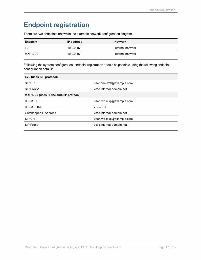
Endpoint registrationThere are two endpoints shown in the example network configuration diagram.
Endpoint IP address Network
E20 10.0.0.15 Internal network
MXP1700 10.0.0.16 Internal network
Following the system configuration, endpoint registration should be possible using the following endpointconfiguration details:
E20 (uses SIP protocol)
SIP URI [email protected]
SIP Proxy1 vcsc.internal-domain.net
MXP1700 (uses H.323 and SIP protocol)
H.323 ID [email protected]
H.323 E.164 7654321
Gatekeeper IP Address vcsc.internal-domain.net
SIP URI [email protected]
SIP Proxy1 vcsc.internal-domain.net

System checks
Cisco VCS Basic Configuration (Single VCS Control) Deployment Guide Page 18 of 32
System checks
Registration statusCheck that all endpoints which are expected to be registered are actually registered to the relevant VCS, andthat they are registering the expected aliases. All successfully registered endpoints will be listed in theRegistrations by device status page (Status > Registrations > By device).
If the expected endpoints are not registered:
n review the endpoint’s registration configurationn review the SIP domain configuration (Step 5)n review any registration restriction configuration applied to the VCS (optional, see Registration restriction
configuration (optional) [p.23])
Call signalingIf calls do not complete, despite the endpoints being successfully registered to a VCS:
n review the VCS Control search rule configurationn check the search history page for search attempts and failures (Status > Search history)n check the event log for call connection failure reasons (Status > Logs > Event Log)

Maintenance routine
Cisco VCS Basic Configuration (Single VCS Control) Deployment Guide Page 19 of 32
Maintenance routine
System backupTo create a system backup:
1. Go to theBackup and restore page (Maintenance > Backup and restore).2. Click Create system backup file.3. Wait for file download dialog to appear.4. Click Save, to save the backup file archive to your local PC.
For more information, seeVCS Administrator Guide.

Optional configuration steps
Cisco VCS Basic Configuration (Single VCS Control) Deployment Guide Page 20 of 32
Optional configuration steps
Cisco TMS configuration (optional)The following configuration enables the VCS systems to be integrated to a Cisco TelePresenceManagementServer (Cisco TMS).
Further configuration steps are required on the Cisco TMS platform to fully integrate the VCS with the CiscoTMS server – seeCisco TMS Administrator Guide.
n Enabling SNMP speeds up the VCS - Cisco TMS integration process but is not essential.
To enable and configure SNMP:
1. Go to theSNMP page (System > SNMP).2. Configure the SNMP fields as follows:
SNMP mode Select v3 plus TMS support
Community name Check that it is public
System contact Enter IT administrator
Location Enter example.com head office
Username Enter VCS
Authentication mode SelectOn
Type Select SHA
Password Enter ex4mpl3.c0m
Privacy mode SelectOn
Type Select AES
Password Enter ex4mpl3.c0m
3. Click Save.

Optional configuration steps
Cisco VCS Basic Configuration (Single VCS Control) Deployment Guide Page 21 of 32
To configure the necessary external manager (Cisco TMS) parameters:
1. Go to theExternal manager page (System > External manager).2. Configure the fields as follows:
Address Enter 10.0.0.14
Path Enter tms/public/external/management/SystemManagementService.asmx
Protocol Select HTTP or HTTPS
Certificate verification mode SelectOn or Off (see Note below)
Note that the certificate is only verified if the value is On and the protocol is set toHTTPS. If you switchthis on then Cisco TMS and VCS must have appropriate certificates.
3. Click Save.
Optional configuration steps
Cisco VCS Basic Configuration (Single VCS Control) Deployment Guide Page 22 of 32
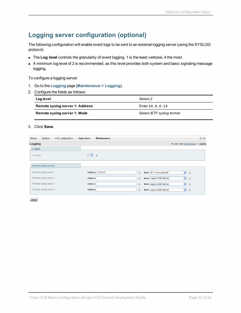
Logging server configuration (optional)The following configuration will enable event logs to be sent to an external logging server (using the SYSLOGprotocol).
n The Log level controls the granularity of event logging. 1 is the least verbose, 4 themost.n A minimum log level of 2 is recommended, as this level provides both system and basic signalingmessage
logging.
To configure a logging server:
1. Go to the Logging page (Maintenance > Logging).2. Configure the fields as follows:
Log level Select 2
Remote syslog server 1: Address Enter 10.0.0.13
Remote syslog server 1: Mode Select IETF syslog format
3. Click Save.

Optional configuration steps
Cisco VCS Basic Configuration (Single VCS Control) Deployment Guide Page 23 of 32
Registration restriction configuration (optional)The aliases that endpoints can register can be limited using either an Allow (white) list or a Deny (black) list.
The following configuration will limit registrations to endpoints which register with an identity that contains“@example.com”.
To configure Allow List registration restrictions:
1. Go to theAllow List page (VCS configuration > Registration > Allow List).2. Click New.3. Create an allow pattern by configuring the fields as the follows:
Description Enter Only allow registrations containing “@example.com”
Pattern type Select Regex
Pattern string Enter .*@example.com
4. Click Add Allow List pattern.
To activate the registration restriction:
1. Go to theRegistration configuration page (VCS configuration > Registration > Configuration).2. Configure theRestriction policy as follows:
Restriction policy Select Allow List
3. Click Save.

Optional configuration steps
Cisco VCS Basic Configuration (Single VCS Control) Deployment Guide Page 24 of 32
Restrict access to ISDN gateways (optional)Cisco VCS users are recommended to take appropriate action to restrict unauthorized access to any ISDNgateway resources (also known as toll-fraud prevention). This optional step shows somemethods in whichthis can be achieved.
In these examples, an ISDN gateway is registered to the VCS Control with a prefix of 9 (and/or has aneighbour zone specified that routes calls starting with a 9).
This example shows how to configure the VCS Control to stop calls coming in from the gateway from beingable to route calls back out of the gateway. This is done by loading some specially constructed CPL onto theVCS Control and configuring its Call policy mode to use Local CPL.
Create a CPL file
The CPL file to be uploaded onto the VCS can be created in a text editor.
Here are 2 example sets of CPL. In these examples:
n “GatewayZone” is the neighbour zone to the ISDN gatewayn “GatewaySubZone” is the subzone to the ISDN gateway (required if the gateway registers the 9 prefix to
the VCS)n Calls coming into the ISDN gateway and hitting a FindMewill not ring devices that use the gateway – for
example, calls forwarded to amobile phone will be disallowed
This example CPL excludes any checking of whether the calling party is authenticated or not:
<?xml version="1.0" encoding="UTF-8" ?><cpl xmlns="urn:ietf:params:xml:ns:cpl"xmlns:taa="http://www.tandberg.net/cpl-extensions"xmlns:xsi="http://www.w3.org/2001/XMLSchema-instance"xsi:schemaLocation="urn:ietf:params:xml:ns:cpl cpl.xsd"><taa:routed><taa:rule-switch><!--Check that gateway is not hairpinning call - Neighbor zone --><taa:rule originating-zone="GatewayZone" destination="9.*"><!-- Calls coming from the gateway are not allowed to send calls back out of this
gateway --><!-- Reject call with a status code of 403 (Forbidden) --><reject status="403" reason="ISDN hairpin call denied"/>
</taa:rule><!-- Check that gateway is not hairpinning call - Subzone for registered gateway --><taa:rule originating-zone="GatewaySubZone" destination="9.*"><!-- Calls coming from the gateway are not allowed to send calls back out of this
gateway --><!-- Reject call with a status code of 403 (Forbidden) --><reject status="403" reason="ISDN hairpin call denied"/>
</taa:rule><taa:rule origin=".*" destination=".*"><!-- All other calls allowed --><proxy/>
</taa:rule></taa:rule-switch>
</taa:routed>

Optional configuration steps
Cisco VCS Basic Configuration (Single VCS Control) Deployment Guide Page 25 of 32
</cpl>
This example CPL also ensures that the calling party is authenticated:
<?xml version="1.0" encoding="UTF-8" ?><cpl xmlns="urn:ietf:params:xml:ns:cpl"xmlns:taa="http://www.tandberg.net/cpl-extensions"xmlns:xsi="http://www.w3.org/2001/XMLSchema-instance"xsi:schemaLocation="urn:ietf:params:xml:ns:cpl cpl.xsd"><taa:routed><taa:rule-switch><!-- Check that calling party is authenticated --><taa:rule authenticated-origin="" destination="9.*"><!-- Reject call with a status code of 403 (Forbidden) --><reject status="403" reason="ISDN call denied as unauthenticated caller"/>
</taa:rule><!-- Check that gateway is not hairpinning call - Neighbor zone --><taa:rule originating-zone="GatewayZone" destination="9.*"><!-- Calls coming from the gateway are not allowed to hairpin and send calls out of
this gateway --><!-- Reject call with a status code of 403 (Forbidden) --><reject status="403" reason="ISDN hairpin call denied"/>
</taa:rule><!-- Check that gateway is not hairpinning call - Subzone for registered gateway --><taa:rule originating-zone="GatewaySubZone" destination="9.*"><!-- Calls coming from the gateway are not allowed to hairpin and send calls out of
this gateway --><!-- Reject call with a status code of 403 (Forbidden) --><reject status="403" reason="ISDN hairpin call denied"/>
</taa:rule><taa:rule origin=".*" destination=".*"><!-- All other calls allowed --><proxy/>
</taa:rule></taa:rule-switch>
</taa:routed></cpl>
Load the CPL onto VCS Control
To configure the VCS Control to use the CPL:
1. Go to theCall Policy configuration page (VCS configuration > Call Policy > Configuration).2. Click Browse... and select your CPL file (created above) from your file system.3. Click Upload file.
l You should receive a "File upload successful" message.l If you receive an "XML invalid" message then youmust correct the problems with the CPL file and
upload it again.4. Select aCall policy mode of Local CPL.5. Click Save.

Optional configuration steps
Cisco VCS Basic Configuration (Single VCS Control) Deployment Guide Page 26 of 32

Appendix 1 – Configuration details
Cisco VCS Basic Configuration (Single VCS Control) Deployment Guide Page 27 of 32
Appendix 1 – Configuration detailsThis appendix summarizes the configuration required for the VCS Control.
VCS Control system configuration
Configuration item Value VCS page
System configuration
System name VCSc System > System
LAN1 IPv4 address 10.0.0.2 System > IP
IPv4 gateway 10.0.0.1 System > IP
LAN1 subnet mask 255.255.255.0 System > IP
DNS server address 1 10.0.0.11 System > DNS
DNS server address 2 10.0.0.12 System > DNS
DNS Domain name internal-domain.net System > DNS
DNS Local host name vcsc System > DNS
NTP server 1 10.0.0.21 System > Time
Time zone GMT System > Time
Protocol configuration
SIP domain name example.com VCS configuration > Protocols > SIP > Domains
VCS Control transforms and search rules
Configuration item Value VCS page
Transform
Pattern string ([^@]*) VCS configuration < Dial plan > Transforms
Pattern type Regex VCS configuration < Dial plan > Transforms
Pattern behavior Replace VCS configuration < Dial plan > Transforms
Replace string \[email protected] VCS configuration < Dial plan > Transforms
Local search rule 1
Rule name Local zone – no domain VCS configuration > Dial plan > Search rules
Priority 48 VCS configuration > Dial plan > Search rules
Source Any VCS configuration > Dial plan > Search rules
Mode Alias pattern match VCS configuration > Dial plan > Search rules
Pattern type Regex VCS configuration > Dial plan > Search rules
Pattern string (.+)@example.com.* VCS configuration > Dial plan > Search rules
Pattern behavior Replace VCS configuration > Dial plan > Search rules
Replace string \1 VCS configuration > Dial plan > Search rules

Appendix 1 – Configuration details
Cisco VCS Basic Configuration (Single VCS Control) Deployment Guide Page 28 of 32
Configuration item Value VCS page
On successful match Continue VCS configuration > Dial plan > Search rules
Target LocalZone VCS configuration > Dial plan > Search rules
Local search rule 2
Rule name Local zone – full URI VCS configuration > Dial plan > Search rules
Priority 50 VCS configuration > Dial plan > Search rules
Source Any VCS configuration > Dial plan > Search rules
Mode Alias pattern match VCS configuration > Dial plan > Search rules
Pattern type Regex VCS configuration > Dial plan > Search rules
Pattern string (.+)@example.com.* VCS configuration > Dial plan > Search rules
Pattern behavior Leave VCS configuration > Dial plan > Search rules
On successful match Continue VCS configuration > Dial plan > Search rules
Target LocalZone VCS configuration > Dial plan > Search rules

Appendix 2 – DNS records configuration
Cisco VCS Basic Configuration (Single VCS Control) Deployment Guide Page 29 of 32
Appendix 2 – DNS records configurationThe following records are required to be configured in the local DNS which hosts the internally routabledomain: internal-domain.net to allow internal endpoints registrationmessages to be routed to the VCSControl.
Local DNS A record
Host TTL Type Data
vcsc.internal-domain.net 86400 A 10.0.0.2
Local DNS SRV records
Service Protocol Host Port Notes
h323cs tcp _h323cs._tcp.internal-domain.net 1720
h323ls udp _h323ls._udp. internal-domain.net 1719
sip tcp _sip._tcp.internal-domain.net 5060
sip udp _sip._udp.internal-domain.net 5060
sips tcp _sips._tcp.internal-domain.net 5061
sips tls _sips._tls.internal-domain.net 5061 For E20 TE2.1
sip tls _sip._tls.internal-domain.net 5061 For MXP F8.2, T150 L6.0, Moviprior to version 3.1
For each DNS SRV record the following values are common:
Name internal-domain.net
TTL 86400
Type SRV
Priority 10
Weight 10
Target vcsc.internal-domain.net.
Checking for updates and getting help
Cisco VCS Basic Configuration (Single VCS Control) Deployment Guide Page 30 of 32
Checking for updates and getting helpIf you experience any problems when configuring or using the product, consult the online help available fromthe user interface. The online help explains how the individual features and settings work.
If you cannot find the answer you need, check the web site athttp://www.cisco.com/cisco/web/support/index.html where you will be able to:
n make sure that you are running themost up-to-date software,n find further relevant documentation, for example product user guides, printable versions of the online help,
reference guides, and articles that cover many frequently asked questions,n get help from the Cisco Technical Support team. Click on Technical Support Overview for information on
Accessing Cisco Technical Services. Make sure you have the following information ready before raising acase:l the serial number and product model number of the unit (if applicable)l the software build number which can be found on the product user interface (if applicable)l your contact email address or telephone numberl a full description of the problem

Document revision history
Cisco VCS Basic Configuration (Single VCS Control) Deployment Guide Page 31 of 32
Document revision historyRevision Date Description
01 September 2009 Initial release.
02 October 2010 New document template applied.
03 Mmmmm 2012 Revised document structure and updated for X7.2.

Disclaimer
Cisco VCS Basic Configuration (Single VCS Control) Deployment Guide Page 32 of 32
THE SPECIFICATIONS AND INFORMATION REGARDING THE PRODUCTS IN THIS MANUAL ARESUBJECT TOCHANGEWITHOUT NOTICE. ALL STATEMENTS, INFORMATION, ANDRECOMMENDATIONS IN THIS MANUAL ARE BELIEVED TOBE ACCURATE BUT ARE PRESENTEDWITHOUTWARRANTY OF ANY KIND, EXPRESS OR IMPLIED. USERS MUST TAKE FULLRESPONSIBILITY FOR THEIR APPLICATION OF ANY PRODUCTS.
THE SOFTWARE LICENSE AND LIMITED WARRANTY FOR THE ACCOMPANYINGPRODUCT ARESET FORTH IN THE INFORMATION PACKET THAT SHIPPED WITH THE PRODUCT AND AREINCORPORATED HEREIN BY THIS REFERENCE. IF YOU ARE UNABLE TO LOCATE THESOFTWARE LICENSE OR LIMITED WARRANTY, CONTACT YOUR CISCOREPRESENTATIVE FORA COPY.
The Cisco implementation of TCP header compression is an adaptation of a program developed by theUniversity of California, Berkeley (UCB) as part of UCB's public domain version of the UNIX operatingsystem. All rights reserved. Copyright © 1981, Regents of the University of California.
NOTWITHSTANDINGANY OTHER WARRANTY HEREIN, ALL DOCUMENT FILES AND SOFTWAREOF THESE SUPPLIERS ARE PROVIDED "AS IS" WITH ALL FAULTS. CISCOAND THE ABOVE-NAMED SUPPLIERS DISCLAIM ALLWARRANTIES, EXPRESSED OR IMPLIED, INCLUDING,WITHOUT LIMITATION, THOSE OFMERCHANTABILITY, FITNESS FOR A PARTICULAR PURPOSEAND NONINFRINGEMENT OR ARISING FROM A COURSE OF DEALING, USAGE, OR TRADEPRACTICE.
IN NOEVENT SHALLCISCOOR ITS SUPPLIERS BE LIABLE FOR ANY INDIRECT, SPECIAL,CONSEQUENTIAL, OR INCIDENTALDAMAGES, INCLUDING, WITHOUT LIMITATION, LOSTPROFITS OR LOSS OR DAMAGE TODATA ARISINGOUTOF THE USE OR INABILITY TOUSE THISMANUAL, EVEN IF CISCOOR ITS SUPPLIERS HAVE BEEN ADVISED OF THE POSSIBILITY OFSUCH DAMAGES.
Cisco and the Cisco Logo are trademarks of Cisco Systems, Inc. and/or its affiliates in the U.S. and othercountries. A listing of Cisco's trademarks can be found at www.cisco.com/go/trademarks. Third partytrademarks mentioned are the property of their respective owners. The use of the word partner does not implya partnership relationship between Cisco and any other company. (1005R)
Any Internet Protocol (IP) addresses and phone numbers used in this document are not intended to be actualaddresses and phone numbers. Any examples, command display output, network topology diagrams, andother figures included in the document are shown for illustrative purposes only. Any use of actual IPaddresses or phone numbers in illustrative content is unintentional and coincidental.
© 2012 Cisco Systems, Inc. All rights reserved.