cisco virtual application container services 2.0 lab...
TRANSCRIPT
Cisco dCloud
© 2015 Cisco and/or its affiliates. All rights reserved. This document is Cisco Public Information. Page 1 of 34
Cisco Virtual Application Container Services 2.0 Lab v1 Last Updated: 02-SEP-2015
About This Solution Cisco Virtual Application Container Services (VACS) enables simplified deployment of Secure Application Containers. It is a complete solution with preconfigured and integrated virtual services, switching, and workflow automation tools. It streamlines policy definitions, integration, and deployment. Cisco VACS accelerates the application and deployment process with compliant containers, or logical network and services descriptions, that work immediately after installation.
Cisco UCS Director (UCSD) enables users to easily deploy Secure Virtual Application Containers on VMWare vSphere based Cloud infrastructure.
VACS enhances UCS Director’s functionality by enabling an Infrastructure Administrator to rapidly create and publish a Secure Application Container to the Service End User.
About This Lab In this demonstration the user will interact with Cisco UCS ® Director (UCSD) in order to deploy a pre-configured Application Container with Virtual Networking, Virtual Edge Firewall and Virtual Compute Firewall features using Cisco’s best in class network services. The pre-configured Application Container is a Three-Tiered Application (Web, App and DB) involving one workload virtual machine per tier and each tier being configured as an individual security zone.
In this self-paced lab, participants will perform four tasks:
As Cloud Infrastructure Admin:
• Walk through the various pre-configured policies that will later be used in the creation of the Secure Application Container template
• Create a Secure Application Container template and publish it for consumption by the Service End User.
As Service End User:
• Deploy a Secure Application Container using the Self-Service Portal interface of UCS Director.
• Configure static NAT and verify functionality of the 3-tier application created in the previous steps
This lab was designed to be completed in sequential order. As some steps rely on the successful completion of previous steps, you are required to complete all steps before moving on.
The individual lab scenarios are:
• Scenario 1: Getting Familiar with UCS Director with VACS
• Scenario 2: Create a New 3-Tier Application Template
• Scenario 3: Publish a Container Template as a Catalog Resource
• Scenario 4: Create a Secure Application Container
• Scenario 5: Verify Secure Application Container Connectivity

Cisco dCloud
© 2015 Cisco and/or its affiliates. All rights reserved. This document is Cisco Public Information. Page 2 of 34
Requirements The table below outlines the requirements for this preconfigured lab.
Table 1. Requirements
Required Optional
● Laptop ● None for this release
Topology The diagram below represents the logical setup of a demo environment. For simplicity of the setup, the external and the management network are the same. Although this is not best practice for production systems, it does not impact the functionality of the VACS solution for demo purposes.
At demo start, the container is not present; it will be deployed as part of the demonstration steps.
Figure 1. dCloud Demonstration Topology

Cisco dCloud
© 2015 Cisco and/or its affiliates. All rights reserved. This document is Cisco Public Information. Page 3 of 34
Figure 2. Logical Lab Setup of a vPod
The lab environment consists of:
• UCS Director with VACS license at 198.18.133.112
• vCenter Server at 198.18.133.211
• One Cisco Nexus 1000V Virtual Supervisor Module, reachable at 198.18.133.40 via SSH.
• Two ESXi nodes with Nexus1000V VEMs reachable at 198.18.133.31 and 198.18.133.32.
• One Prime Network Services Controller at 198.18.133.85
• One Windows 7 workstation (with RDP enabled) at 198.18.133.36
• One pre-configured upstream switch to which you do not have access
All necessary applications used within this lab are available on the desktop of the control center machine, to which you are connected via Remote Desktop Protocol (RDP).
Get Started
BEFORE PRESENTING
We strongly recommend that you go through this document and work with an active session before presenting in front of a live audience. This will allow you to become familiar with the structure of the document and content.
PREPARATION IS KEY TO A SUCCESSFUL PRESENTATION.
Follow the steps to schedule a session of the content and configure your presentation environment.
1. Browse to dcloud.cisco.com, select the location closest to you, and log in with your Cisco.com credentials.
2. Schedule a session. [Show Me How]
Cisco dCloud
© 2015 Cisco and/or its affiliates. All rights reserved. This document is Cisco Public Information. Page 4 of 34
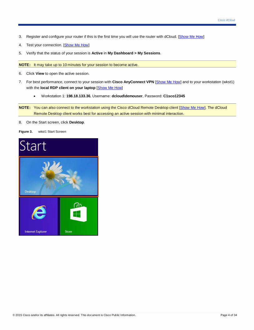
3. Register and configure your router if this is the first time you will use the router with dCloud. [Show Me How]
4. Test your connection. [Show Me How]
5. Verify that the status of your session is Active in My Dashboard > My Sessions.
NOTE: It may take up to 10 minutes for your session to become active.
6. Click View to open the active session.
7. For best performance, connect to your session with Cisco AnyConnect VPN [Show Me How] and to your workstation (wkst1) with the local RDP client on your laptop [Show Me How]
• Workstation 1: 198.18.133.36, Username: dcloud\demouser, Password: C1sco12345
NOTE: You can also connect to the workstation using the Cisco dCloud Remote Desktop client [Show Me How]. The dCloud Remote Desktop client works best for accessing an active session with minimal interaction.
8. On the Start screen, click Desktop.
Figure 3. wkst1 Start Screen
Cisco dCloud
© 2015 Cisco and/or its affiliates. All rights reserved. This document is Cisco Public Information. Page 5 of 34
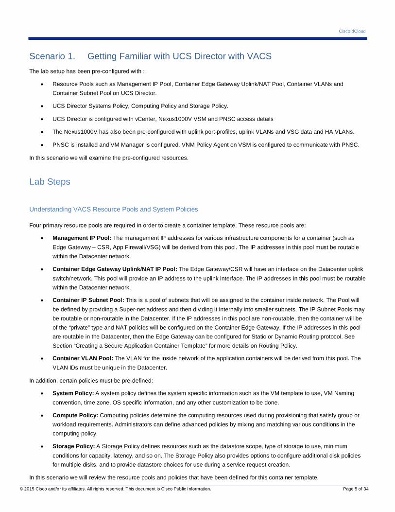
Scenario 1. Getting Familiar with UCS Director with VACS The lab setup has been pre-configured with :
• Resource Pools such as Management IP Pool, Container Edge Gateway Uplink/NAT Pool, Container VLANs and Container Subnet Pool on UCS Director.
• UCS Director Systems Policy, Computing Policy and Storage Policy.
• UCS Director is configured with vCenter, Nexus1000V VSM and PNSC access details
• The Nexus1000V has also been pre-configured with uplink port-profiles, uplink VLANs and VSG data and HA VLANs.
• PNSC is installed and VM Manager is configured. VNM Policy Agent on VSM is configured to communicate with PNSC.
In this scenario we will examine the pre-configured resources.
Lab Steps
Understanding VACS Resource Pools and System Policies
Four primary resource pools are required in order to create a container template. These resource pools are:
• Management IP Pool: The management IP addresses for various infrastructure components for a container (such as Edge Gateway – CSR, App Firewall/VSG) will be derived from this pool. The IP addresses in this pool must be routable within the Datacenter network.
• Container Edge Gateway Uplink/NAT IP Pool: The Edge Gateway/CSR will have an interface on the Datacenter uplink switch/network. This pool will provide an IP address to the uplink interface. The IP addresses in this pool must be routable within the Datacenter network.
• Container IP Subnet Pool: This is a pool of subnets that will be assigned to the container inside network. The Pool will be defined by providing a Super-net address and then dividing it internally into smaller subnets. The IP Subnet Pools may be routable or non-routable in the Datacenter. If the IP addresses in this pool are non-routable, then the container will be of the “private” type and NAT policies will be configured on the Container Edge Gateway. If the IP addresses in this pool are routable in the Datacenter, then the Edge Gateway can be configured for Static or Dynamic Routing protocol. See Section “Creating a Secure Application Container Template” for more details on Routing Policy.
• Container VLAN Pool: The VLAN for the inside network of the application containers will be derived from this pool. The VLAN IDs must be unique in the Datacenter.
In addition, certain policies must be pre-defined:
• System Policy: A system policy defines the system specific information such as the VM template to use, VM Naming convention, time zone, OS specific information, and any other customization to be done.
• Compute Policy: Computing policies determine the computing resources used during provisioning that satisfy group or workload requirements. Administrators can define advanced policies by mixing and matching various conditions in the computing policy.
• Storage Policy: A Storage Policy defines resources such as the datastore scope, type of storage to use, minimum conditions for capacity, latency, and so on. The Storage Policy also provides options to configure additional disk policies for multiple disks, and to provide datastore choices for use during a service request creation.
In this scenario we will review the resource pools and policies that have been defined for this container template.

Cisco dCloud
© 2015 Cisco and/or its affiliates. All rights reserved. This document is Cisco Public Information. Page 6 of 34
Verifying Network Policies
In this section you will verify the Management IP Pool and the Container Edge Gateway Uplink/NAT IP Pool.
1. On the desktop, double click the UCSD Login shortcut and log in to UCS Director (admin/C1sco12345).
NOTE: There may be a delay of up to a few minutes while UCS Director starts.
2. From the top menu, click Policies > Virtual/Hypervisor Policies > Network.
Figure 4. Network Policies Menu Sequence
3. Click the Static IP Pool Policy tab to view the Static IP Pool Policy table. Both the Management IP Pool and Edge Gateway/CSR Uplink Pool are defined in this table.
Figure 5. Static IP Pool Policy
4. Click Device Management Pool to highlight it.
Figure 6. Device Management Pool
5. Click to display details of the Device Management Pool. Note the IP start-end range allocated to this pool, the subnet mask, Default Gateway IP and VLAN ID for this network.

Cisco dCloud
© 2015 Cisco and/or its affiliates. All rights reserved. This document is Cisco Public Information. Page 7 of 34
Figure 7. Device Management Pool Details
6. Click Close to return to the previous screen (Static IP Pool Policy).
7. Highlight the Router Uplink Pool and click to display the details of the Edge Gateway Uplink Pool.
Figure 8. UCS Director Router Uplink Pool
8. Click Close to return to previous screen (Static IP Pool Policy).
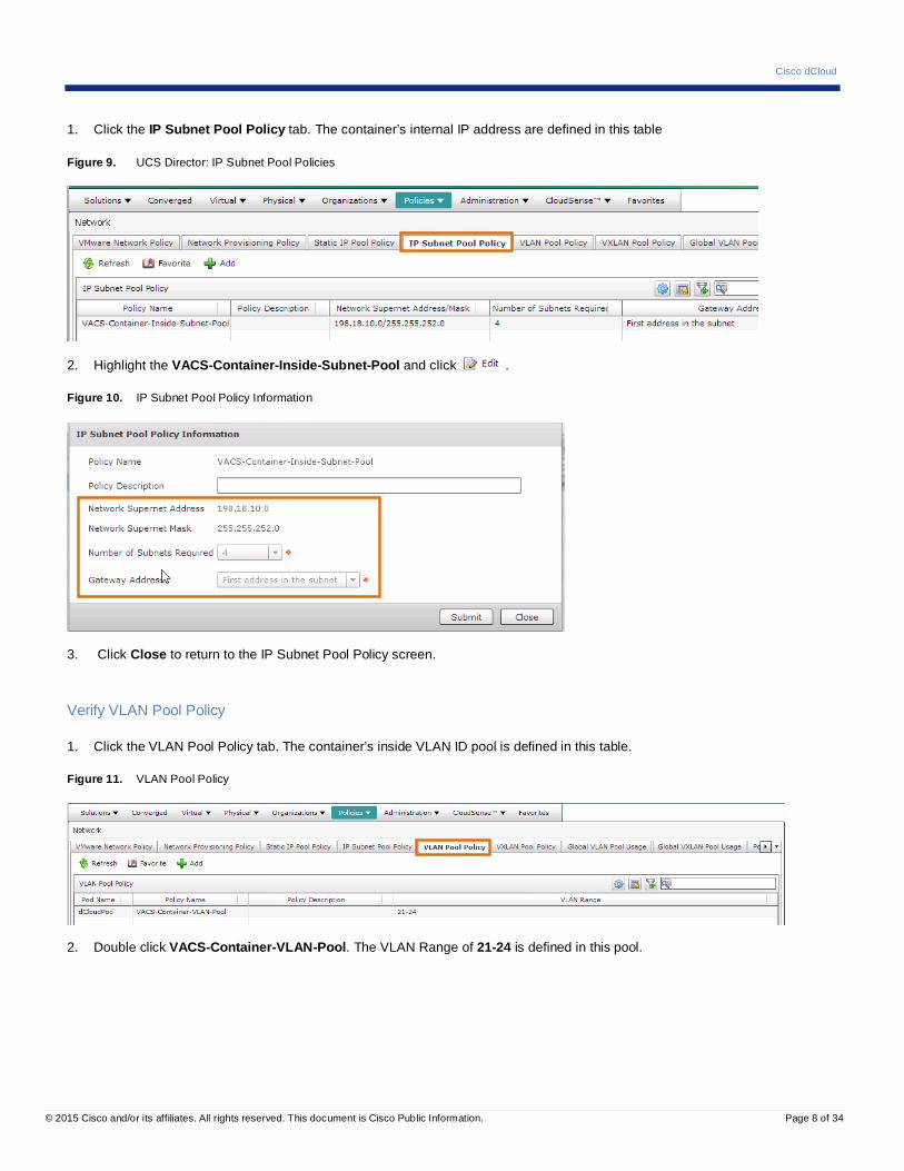
Verify Subnet Pool Policy
In this section we will verify the settings for the IP Subnet Pool.
In this policy, the Supernet Address is defined as a /22 mask and the Number of Subnets Required is set to 4. This setting would result in 4 IP Pools of /24 mask. However, this solution performs all the subnet calculations for the Administrator. You will also see that the Container inside gateway is set to be first IP in the subnet.
In our example, the Supernet 198.18.10.0/22 will be divided into 4 subnets:
• Subnet 1: 198.18.4.0/24 with Gateway a 198.18.8.1 • Subnet 2: 198.18.5.0/24 with Gateway a 198.18.9.1 • Subnet 3: 198.18.6.0/24 with Gateway a 198.18.10.1 • Subnet 4: 198.18.7.0/24 with Gateway a 198.18.11.1
Cisco dCloud
© 2015 Cisco and/or its affiliates. All rights reserved. This document is Cisco Public Information. Page 8 of 34
1. Click the IP Subnet Pool Policy tab. The container’s internal IP address are defined in this table
Figure 9. UCS Director: IP Subnet Pool Policies
2. Highlight the VACS-Container-Inside-Subnet-Pool and click .
Figure 10. IP Subnet Pool Policy Information
3. Click Close to return to the IP Subnet Pool Policy screen.
Verify VLAN Pool Policy
1. Click the VLAN Pool Policy tab. The container’s inside VLAN ID pool is defined in this table.
Figure 11. VLAN Pool Policy
2. Double click VACS-Container-VLAN-Pool. The VLAN Range of 21-24 is defined in this pool.

Cisco dCloud
© 2015 Cisco and/or its affiliates. All rights reserved. This document is Cisco Public Information. Page 9 of 34
Figure 12. VACS-Container VLAN Pool
3. Click Close to return to the VLAN Pool Policy screen.
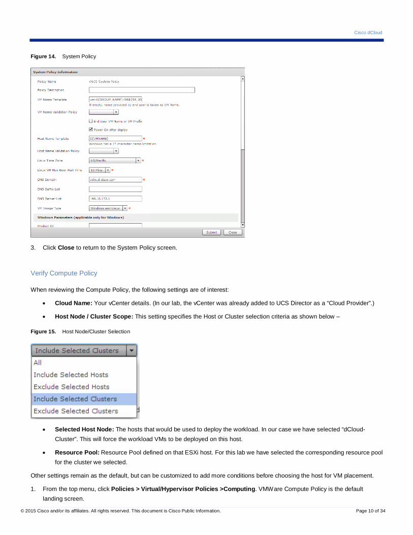
Verify System Policy
Some of the System Policy settings can be customized on the deployed VM, if VMware Tools are present in the VM template.
• VM Name Template: Naming Convention of the Created VM – variables such as $GROUP_NAME and $SR_ID will be substituted with the Service End User’s group name and the Service Request ID.
• Host Name Template: The host name of the deployed VM.
• DNS domain: The IP domain to use for the VM
• Linux Time Zone: Time zone to be configured for the VM
• DNS Server list: The list of DNS server IP addresses.
1. From the top menu, click Policies > Virtual/Hypervisor Policies > Service Delivery. The VMWare System Policy tab is the default landing screen.
Figure 13. Service Delivery
2. Double-click VACS System Policy to display the details of the policy.
Cisco dCloud
© 2015 Cisco and/or its affiliates. All rights reserved. This document is Cisco Public Information. Page 10 of 34
Figure 14. System Policy
3. Click Close to return to the System Policy screen.
Verify Compute Policy
When reviewing the Compute Policy, the following settings are of interest:
• Cloud Name: Your vCenter details. (In our lab, the vCenter was already added to UCS Director as a “Cloud Provider”.)
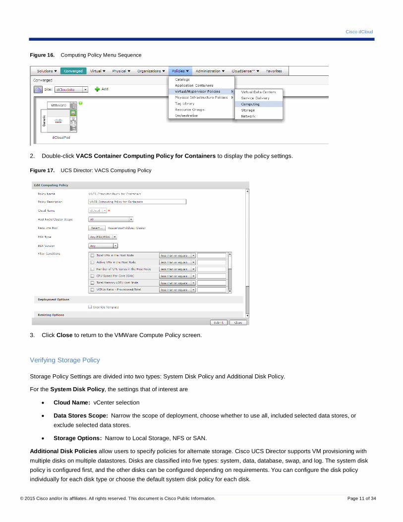
• Host Node / Cluster Scope: This setting specifies the Host or Cluster selection criteria as shown below –
Figure 15. Host Node/Cluster Selection
• Selected Host Node: The hosts that would be used to deploy the workload. In our case we have selected “dCloud-Cluster”. This will force the workload VMs to be deployed on this host.
• Resource Pool: Resource Pool defined on that ESXi host. For this lab we have selected the corresponding resource pool for the cluster we selected.
Other settings remain as the default, but can be customized to add more conditions before choosing the host for VM placement.
1. From the top menu, click Policies > Virtual/Hypervisor Policies >Computing. VMWare Compute Policy is the default landing screen.
Cisco dCloud
© 2015 Cisco and/or its affiliates. All rights reserved. This document is Cisco Public Information. Page 11 of 34
Figure 16. Computing Policy Menu Sequence
2. Double-click VACS Container Computing Policy for Containers to display the policy settings.
Figure 17. UCS Director: VACS Computing Policy
3. Click Close to return to the VMWare Compute Policy screen.
Verifying Storage Policy
Storage Policy Settings are divided into two types: System Disk Policy and Additional Disk Policy.
For the System Disk Policy, the settings that of interest are
• Cloud Name: vCenter selection
• Data Stores Scope: Narrow the scope of deployment, choose whether to use all, included selected data stores, or exclude selected data stores.
• Storage Options: Narrow to Local Storage, NFS or SAN.
Additional Disk Policies allow users to specify policies for alternate storage. Cisco UCS Director supports VM provisioning with multiple disks on multiple datastores. Disks are classified into five types: system, data, database, swap, and log. The system disk policy is configured first, and the other disks can be configured depending on requirements. You can configure the disk policy individually for each disk type or choose the default system disk policy for each disk.

Cisco dCloud
© 2015 Cisco and/or its affiliates. All rights reserved. This document is Cisco Public Information. Page 12 of 34
1. From the main menu, click Policies > Virtual/Hypervisor Policies > Storage.
Figure 18. Storage Policy Menu Sequence
2. Click the VMware Storage Policy tab.
Figure 19. VMware Storage Policy Tab
3. Double-click VACS Storage Policy to display the Storage Policy settings. The System Disk policies are shown on the landing screen.
Figure 20. System Disk Policy
4. Click Next to view the Additional Disk Policies.
Cisco dCloud
© 2015 Cisco and/or its affiliates. All rights reserved. This document is Cisco Public Information. Page 13 of 34
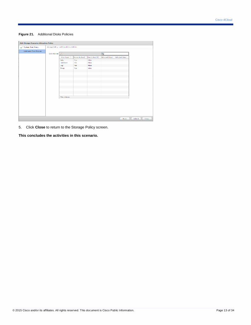
Figure 21. Additional Disks Policies
5. Click Close to return to the Storage Policy screen.
This concludes the activities in this scenario.
Cisco dCloud
© 2015 Cisco and/or its affiliates. All rights reserved. This document is Cisco Public Information. Page 14 of 34
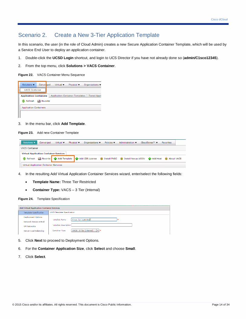
Scenario 2. Create a New 3-Tier Application Template In this scenario, the user (in the role of Cloud Admin) creates a new Secure Application Container Template, which will be used by a Service End User to deploy an application container.
1. Double-click the UCSD Login shortcut, and login to UCS Director if you have not already done so (admin/C1sco12345).
2. From the top menu, click Solutions > VACS Container.
Figure 22. VACS Container Menu Sequence
3. In the menu bar, click Add Template.
Figure 23. Add new Container Template
4. In the resulting Add Virtual Application Container Services wizard, enter/select the following fields:
• Template Name: Three Tier Restricted
• Container Type: VACS – 3 Tier (Internal)
Figure 24. Template Specification
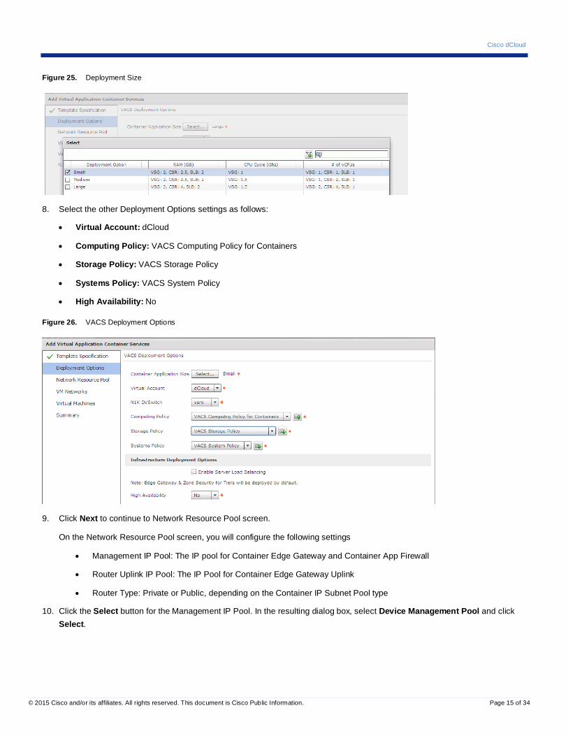
5. Click Next to proceed to Deployment Options.
6. For the Container Application Size, click Select and choose Small.
7. Click Select.
Cisco dCloud
© 2015 Cisco and/or its affiliates. All rights reserved. This document is Cisco Public Information. Page 15 of 34
Figure 25. Deployment Size
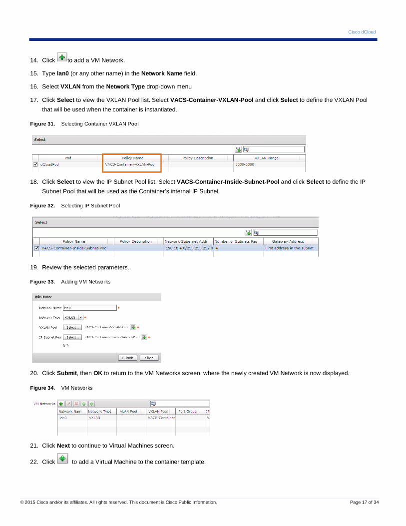
8. Select the other Deployment Options settings as follows:
• Virtual Account: dCloud
• Computing Policy: VACS Computing Policy for Containers
• Storage Policy: VACS Storage Policy
• Systems Policy: VACS System Policy
• High Availability: No
Figure 26. VACS Deployment Options
9. Click Next to continue to Network Resource Pool screen.
On the Network Resource Pool screen, you will configure the following settings
• Management IP Pool: The IP pool for Container Edge Gateway and Container App Firewall
• Router Uplink IP Pool: The IP Pool for Container Edge Gateway Uplink
• Router Type: Private or Public, depending on the Container IP Subnet Pool type
10. Click the Select button for the Management IP Pool. In the resulting dialog box, select Device Management Pool and click Select.

Cisco dCloud
© 2015 Cisco and/or its affiliates. All rights reserved. This document is Cisco Public Information. Page 16 of 34
Figure 27. Selecting Management IP Pool
11. Click the Select button for the Router Uplink Pool. In the resulting dialog box, select Router Uplink Pool and click Select.
Figure 28. Selecting Router Uplink Pool
12. Select Public from the Router IP Type drop-down to view additional configuration options. For this lab, we will not use the Public IP Type, so do not click Next.
NOTE: This will expose additional configuration options for the Container Edge Gateway. The supported L3 Routing Protocols are Static and EIGRP. Depending on the selected Routing Protocol option, additional configuration options such as EIGRP Autonomous System Number, MTU are displayed.
Figure 29. Additional Configuration Options of Public IPs
13. Select Private from the Router IP Type drop-down and click Next to proceed to the VM Networks screen and configure the container’s internal network.
Figure 30. Select IP Type
Cisco dCloud
© 2015 Cisco and/or its affiliates. All rights reserved. This document is Cisco Public Information. Page 17 of 34
14. Click to add a VM Network.
15. Type lan0 (or any other name) in the Network Name field.
16. Select VXLAN from the Network Type drop-down menu
17. Click Select to view the VXLAN Pool list. Select VACS-Container-VXLAN-Pool and click Select to define the VXLAN Pool that will be used when the container is instantiated.
Figure 31. Selecting Container VXLAN Pool
18. Click Select to view the IP Subnet Pool list. Select VACS-Container-Inside-Subnet-Pool and click Select to define the IP Subnet Pool that will be used as the Container’s internal IP Subnet.
Figure 32. Selecting IP Subnet Pool
19. Review the selected parameters.
Figure 33. Adding VM Networks
20. Click Submit, then OK to return to the VM Networks screen, where the newly created VM Network is now displayed.
Figure 34. VM Networks
21. Click Next to continue to Virtual Machines screen.
22. Click to add a Virtual Machine to the container template.
Cisco dCloud
© 2015 Cisco and/or its affiliates. All rights reserved. This document is Cisco Public Information. Page 18 of 34
NOTE: The following steps will add a VM to the WebZone security zone. When this is completed, you will repeat the procedure to add a VM to the AppZone and the DBZone, ending up with one VM in each zone. Adding additional VMs to a security zone is supported, but beyond the scope of this lab.
23. Configure the VM as follows:
a. Security Zone: For the first VM, select WebZone, for the two subsequent VMs select AppZone and DBZone
b. VM Name: Provide a name that will be appended to the VM Name:
o WebZone: frontend
o AppZone: middle
o DBZone: backend
c. VM Image: Select web-template for WebZone, and so forth
d. Memory: Select 1024
e. Uncheck the Use Network Configuration from Image checkbox. Failure to do so will result in incorrect IP address on the VM.
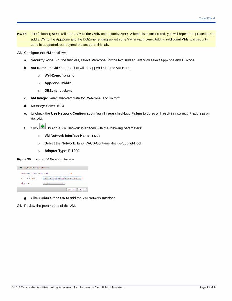
f. Click to add a VM Network Interfaces with the following parameters:
o VM Network Interface Name: inside
o Select the Network: lan0 [VACS-Container-Inside-Subnet-Pool]
o Adapter Type: E 1000
Figure 35. Add a VM Network Interface
g. Click Submit, then OK to add the VM Network Interface.
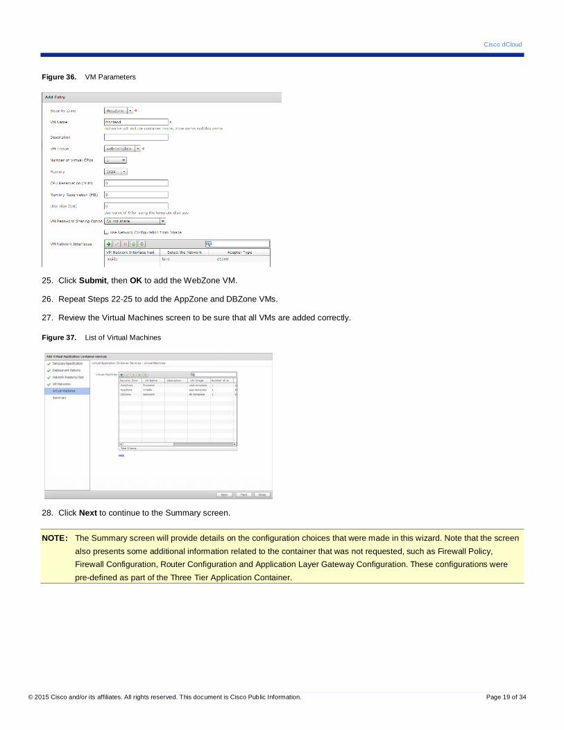
24. Review the parameters of the VM.
Cisco dCloud
© 2015 Cisco and/or its affiliates. All rights reserved. This document is Cisco Public Information. Page 19 of 34
Figure 36. VM Parameters
25. Click Submit, then OK to add the WebZone VM.
26. Repeat Steps 22-25 to add the AppZone and DBZone VMs.
27. Review the Virtual Machines screen to be sure that all VMs are added correctly.
Figure 37. List of Virtual Machines
28. Click Next to continue to the Summary screen.
NOTE: The Summary screen will provide details on the configuration choices that were made in this wizard. Note that the screen also presents some additional information related to the container that was not requested, such as Firewall Policy, Firewall Configuration, Router Configuration and Application Layer Gateway Configuration. These configurations were pre-defined as part of the Three Tier Application Container.

Cisco dCloud
© 2015 Cisco and/or its affiliates. All rights reserved. This document is Cisco Public Information. Page 20 of 34
Figure 38. VACS Container Template Summary
29. Click Submit, then OK to save the Container Template.
30. Review the Container Template list, which now displays the newly-created Three Tier Restricted template.
Figure 39. VACS Container Template List
This concludes the activities in this scenario.
Cisco dCloud
© 2015 Cisco and/or its affiliates. All rights reserved. This document is Cisco Public Information. Page 21 of 34
Scenario 3. Publish a Container Template as a Catalog Resource In this scenario the user, acting as a Cloud Administrator, publishes the newly created container template to the catalog, where Service End Users can utilize it to construct their own three-tier applications.
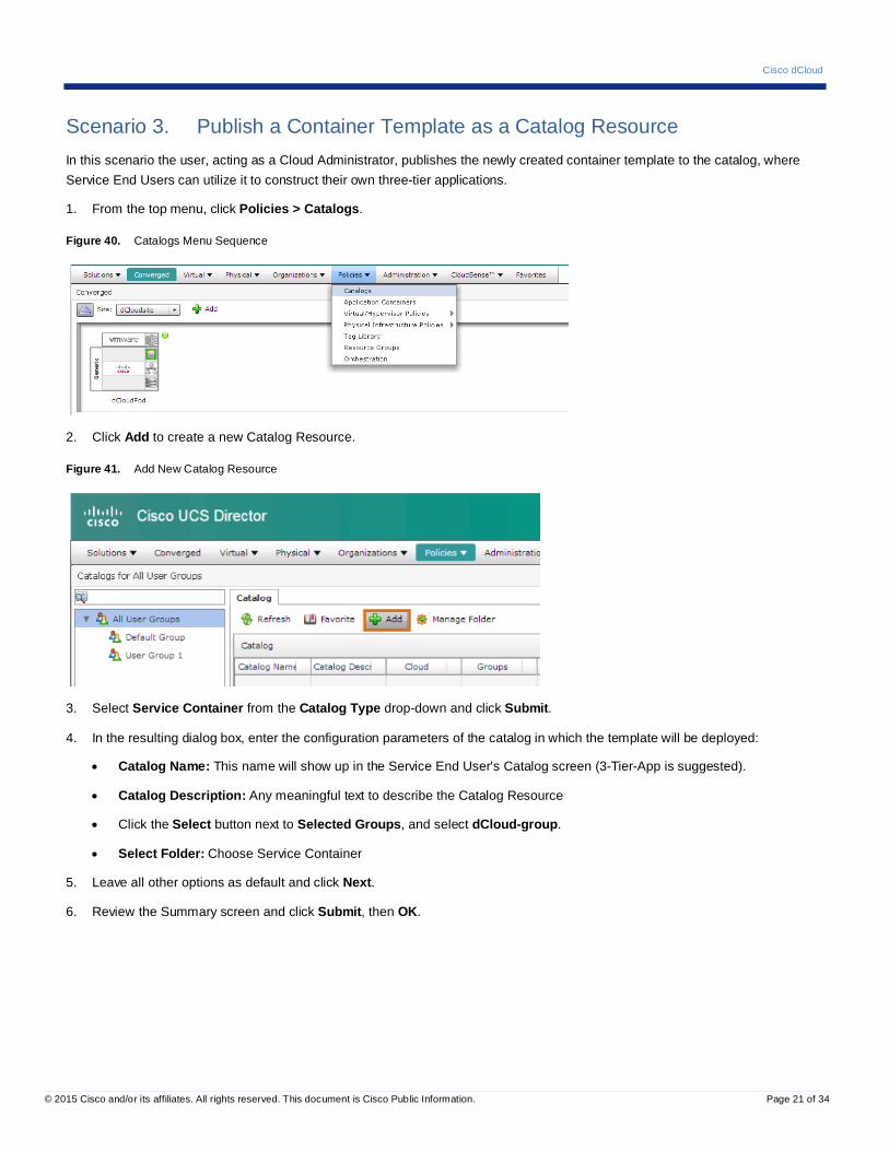
1. From the top menu, click Policies > Catalogs.
Figure 40. Catalogs Menu Sequence
2. Click Add to create a new Catalog Resource.
Figure 41. Add New Catalog Resource
3. Select Service Container from the Catalog Type drop-down and click Submit.
4. In the resulting dialog box, enter the configuration parameters of the catalog in which the template will be deployed:
• Catalog Name: This name will show up in the Service End User’s Catalog screen (3-Tier-App is suggested).
• Catalog Description: Any meaningful text to describe the Catalog Resource
• Click the Select button next to Selected Groups, and select dCloud-group.
• Select Folder: Choose Service Container
5. Leave all other options as default and click Next.
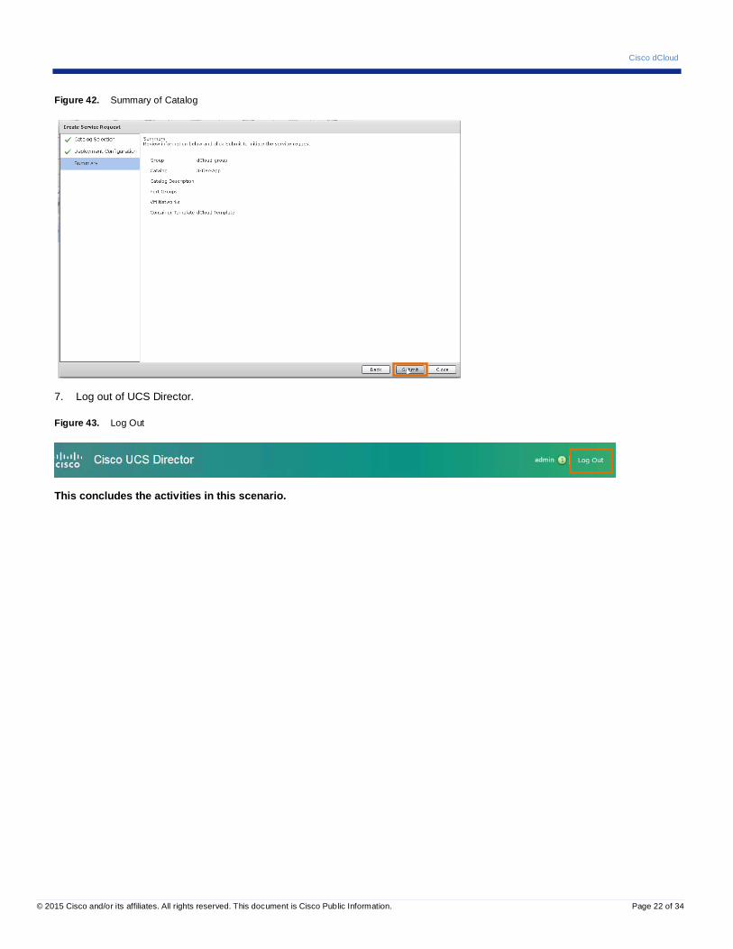
6. Review the Summary screen and click Submit, then OK.
Cisco dCloud
© 2015 Cisco and/or its affiliates. All rights reserved. This document is Cisco Public Information. Page 22 of 34
Figure 42. Summary of Catalog
7. Log out of UCS Director.
Figure 43. Log Out
This concludes the activities in this scenario.
Cisco dCloud
© 2015 Cisco and/or its affiliates. All rights reserved. This document is Cisco Public Information. Page 23 of 34
Scenario 4. Create a Secure Application Container In this scenario, participants act as Service End Users and request the deployment of a pre-configured Secure Application Container from a published catalog.
Demonstration Steps
Requesting a Secure Application Container
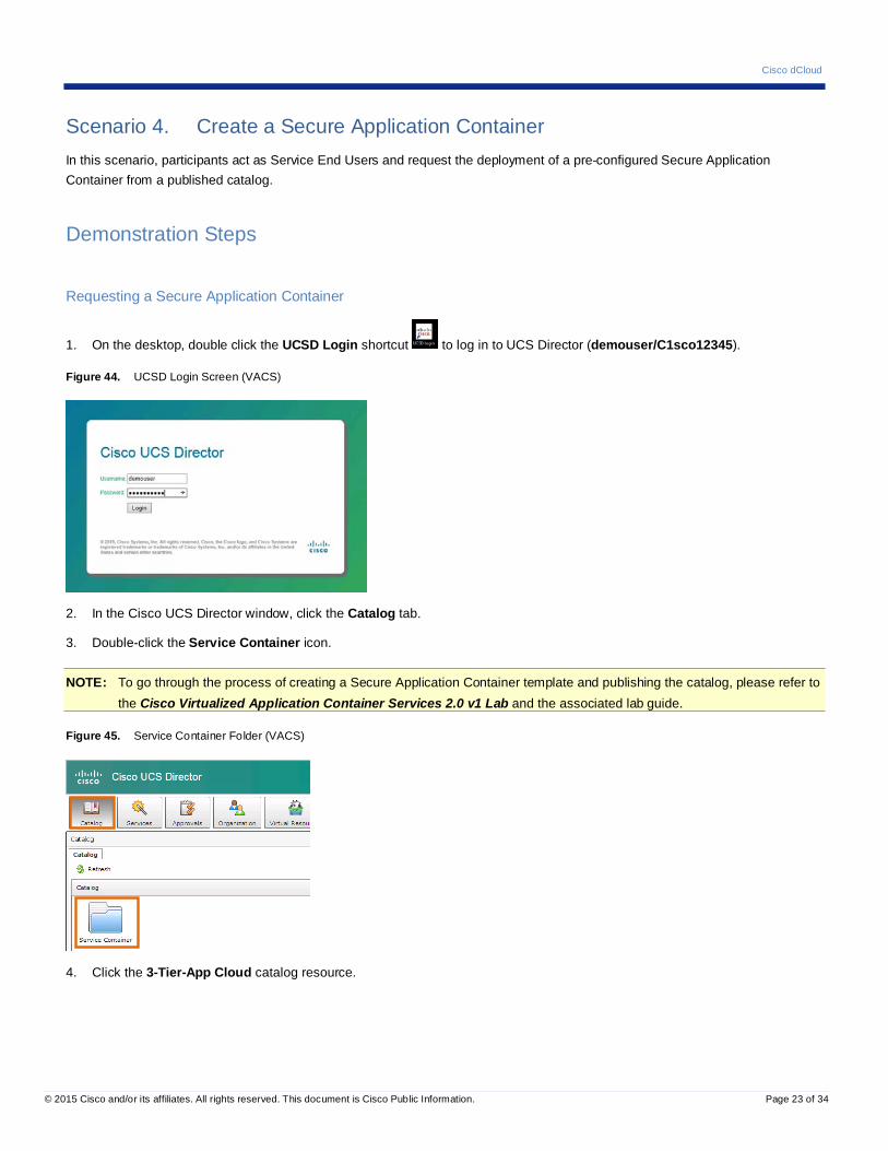
1. On the desktop, double click the UCSD Login shortcut to log in to UCS Director (demouser/C1sco12345).
Figure 44. UCSD Login Screen (VACS)
2. In the Cisco UCS Director window, click the Catalog tab.
3. Double-click the Service Container icon.
NOTE: To go through the process of creating a Secure Application Container template and publishing the catalog, please refer to the Cisco Virtualized Application Container Services 2.0 v1 Lab and the associated lab guide.
Figure 45. Service Container Folder (VACS)
4. Click the 3-Tier-App Cloud catalog resource.
Cisco dCloud
© 2015 Cisco and/or its affiliates. All rights reserved. This document is Cisco Public Information. Page 24 of 34
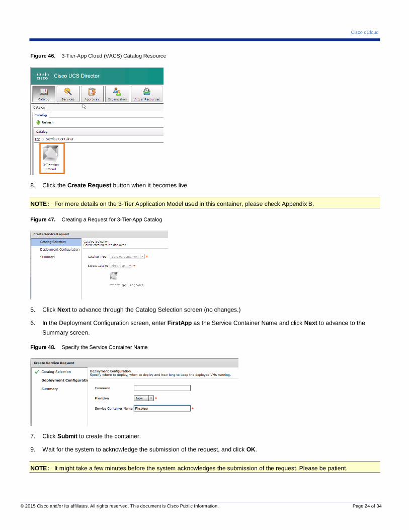
Figure 46. 3-Tier-App Cloud (VACS) Catalog Resource
8. Click the Create Request button when it becomes live.
NOTE: For more details on the 3-Tier Application Model used in this container, please check Appendix B.
Figure 47. Creating a Request for 3-Tier-App Catalog
5. Click Next to advance through the Catalog Selection screen (no changes.)
6. In the Deployment Configuration screen, enter FirstApp as the Service Container Name and click Next to advance to the Summary screen.
Figure 48. Specify the Service Container Name
7. Click Submit to create the container.
9. Wait for the system to acknowledge the submission of the request, and click OK.
NOTE: It might take a few minutes before the system acknowledges the submission of the request. Please be patient.
Cisco dCloud
© 2015 Cisco and/or its affiliates. All rights reserved. This document is Cisco Public Information. Page 25 of 34
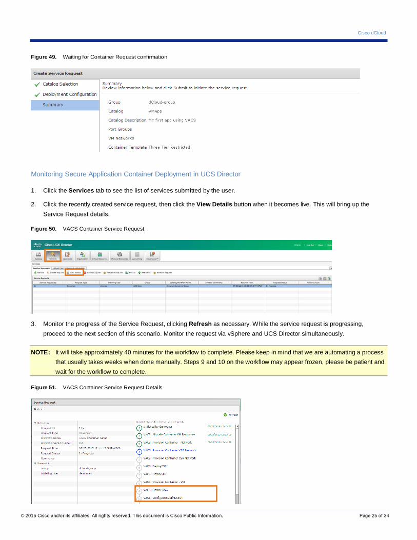
Figure 49. Waiting for Container Request confirmation
Monitoring Secure Application Container Deployment in UCS Director
1. Click the Services tab to see the list of services submitted by the user.
2. Click the recently created service request, then click the View Details button when it becomes live. This will bring up the Service Request details.
Figure 50. VACS Container Service Request
3. Monitor the progress of the Service Request, clicking Refresh as necessary. While the service request is progressing, proceed to the next section of this scenario. Monitor the request via vSphere and UCS Director simultaneously.
NOTE: It will take approximately 40 minutes for the workflow to complete. Please keep in mind that we are automating a process that usually takes weeks when done manually. Steps 9 and 10 on the workflow may appear frozen, please be patient and wait for the workflow to complete.
Figure 51. VACS Container Service Request Details
Cisco dCloud
© 2015 Cisco and/or its affiliates. All rights reserved. This document is Cisco Public Information. Page 26 of 34
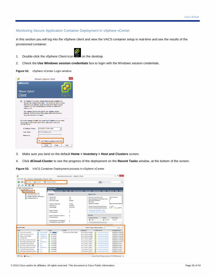
Monitoring Secure Application Container Deployment in vSphere vCenter
In this section you will log into the vSphere client and view the VACS container setup in real-time and see the results of the provisioned container.
1. Double-click the vSphere Client icon on the desktop.
2. Check the Use Windows session credentials box to login with the Windows session credentials.
Figure 52. vSphere vCenter Login window
3. Make sure you land on the default Home > Inventory > Host and Clusters screen.
4. Click dCloud-Cluster to see the progress of the deployment on the Recent Tasks window, at the bottom of the screen.
Figure 53. VACS Container Deployment process in vSphere vCenter

Cisco dCloud
© 2015 Cisco and/or its affiliates. All rights reserved. This document is Cisco Public Information. Page 27 of 34
5. Watch the application VMs drop into the dCloud-Cluster. Five VMs will be created:
• FirstApp_WebZone_Webserver-1
• FirstApp_AppZone_AppServer-1
• FirstApp_DBZone_DBServer-1
• FirstApp-primary-csr
• FirstApp-primary-vsg
View Secure Application Container Report
Once the deployment is complete, the user can request a report in order to see the details of the container’s components.
1. In the UCS Director window, click the Virtual Resources tab, then click Application Containers.
Figure 54. Display a List of Application Containers
2. Click the FirstApp container, then click View Reports.
Figure 55. View Reports
3. Select Summary in the drop-down and click Submit to generate the Container Summary Report.
Figure 56. VACS Container Report Submit
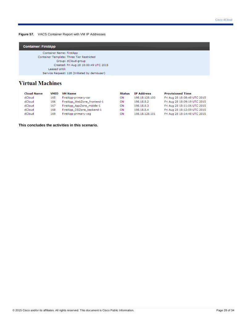
4. Review the list of VMs and their associated IP addresses.
Cisco dCloud
© 2015 Cisco and/or its affiliates. All rights reserved. This document is Cisco Public Information. Page 28 of 34
Figure 57. VACS Container Report with VM IP Addresses
This concludes the activities in this scenario.

Cisco dCloud
© 2015 Cisco and/or its affiliates. All rights reserved. This document is Cisco Public Information. Page 29 of 34
Scenario 5. Verify Secure Application Container Connectivity
In this scenario, the users will verify connectivity within the Secure Application Container. In order to achieve this, users will have to request Static NAT configuration on the deployed CSR Router so access is granted from the external network (where the demo workstation, wkst1 resides) to the container’s web tier.
Demonstration Steps
In this section, you will request Static NAT on the deployed CSR to allow connectivity to the deployed container from the External Network.
Configure Static NAT
1. Login to the UCS Director portal if you are not already logged in (demouser/C1sco12345).
2. Click the Virtual Resources tab, then click the Application Containers tab.
Figure 58. VACS Application Container List
3. Click the newly created Application Container (FirstApp, if you used that name for your container). Click the Static NAT button when it becomes live.
Figure 59. VACS Application Container List (showing Static NAT option)
4. Select FirstApp_WebZone_WebServer-1 from the list to configure Static NAT on that VM, and then click Submit.
Cisco dCloud
© 2015 Cisco and/or its affiliates. All rights reserved. This document is Cisco Public Information. Page 30 of 34
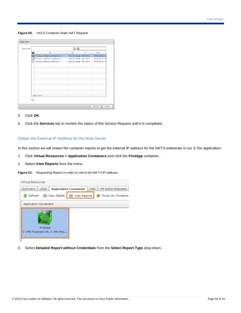
Figure 60. VACS Container Static NAT Request
5. Click OK.
6. Click the Services tab to monitor the status of this Service Request until it is completed.
Obtain the External IP Address for the Web Server
In this section we will review the container reports to get the external IP address for the NAT’d webserver in our 3-Tier application.
1. Click Virtual Resources > Application Containers and click the FirstApp container.
2. Select View Reports from the menu.
Figure 61. Requesting Report in order to check the NAT’d IP address.
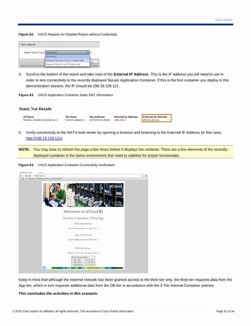
3. Select Detailed Report without Credentials from the Select Report Type drop-down.
Cisco dCloud
© 2015 Cisco and/or its affiliates. All rights reserved. This document is Cisco Public Information. Page 31 of 34
Figure 62. VACS Request for Detailed Report without Credentials
4. Scroll to the bottom of the report and take note of the External IP Address. This is the IP address you will need to use in order to test connectivity to the recently deployed Secure Application Container. If this is the first container you deploy in this demonstration session, the IP should be 198.18.128.121.
Figure 63. VACS Application Container Static NAT Information
5. Verify connectivity to the NAT’d web server by opening a browser and browsing to the External IP Address (in this case, http://198.18.128.121).
NOTE: You may have to refresh the page a few times before it displays the contents. There are a few elements of the recently-deployed container in the demo environment that need to stabilize for proper functionality.
Figure 64. VACS Application Container Connectivity Verification
Keep in mind that although the external network has been granted access to the Web tier only, the Web tier requests data from the App tier, which in turn requests additional data from the DB tier in accordance with the 3-Tier Internal Container policies.
This concludes the activities in this scenario.
Cisco dCloud
© 2015 Cisco and/or its affiliates. All rights reserved. This document is Cisco Public Information. Page 32 of 34
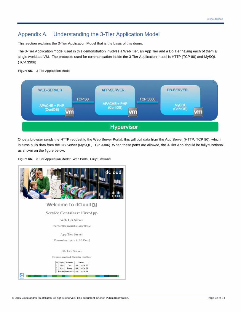
Appendix A. Understanding the 3-Tier Application Model This section explains the 3-Tier Application Model that is the basis of this demo.
The 3-Tier Application model used in this demonstration involves a Web Tier, an App Tier and a Db Tier having each of them a single workload VM. The protocols used for communication inside the 3-Tier Application model is HTTP (TCP 80) and MySQL (TCP 3306)
Figure 65. 3 Tier Application Model
Once a browser sends the HTTP request to the Web Server Portal; this will pull data from the App Server (HTTP, TCP 80), which in turns pulls data from the DB Server (MySQL, TCP 3306). When these ports are allowed, the 3-Tier App should be fully functional as shown on the figure below.
Figure 66. 3 Tier Application Model: Web Portal, Fully functional
Cisco dCloud
© 2015 Cisco and/or its affiliates. All rights reserved. This document is Cisco Public Information. Page 33 of 34
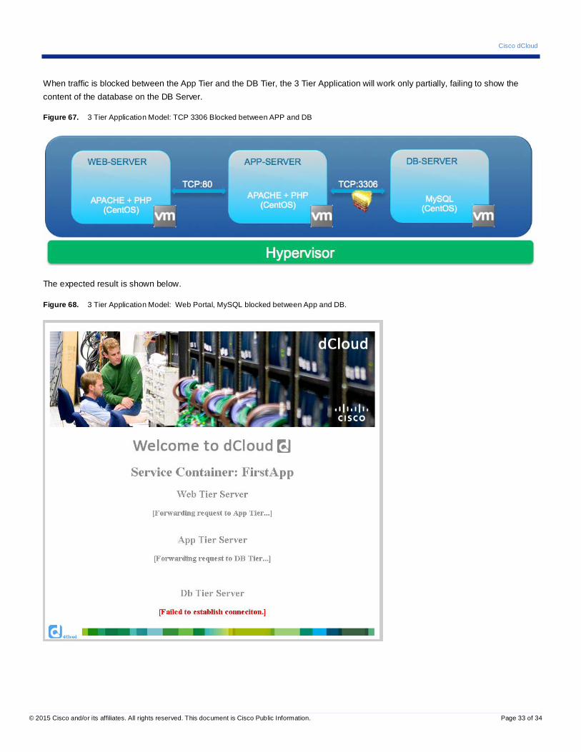
When traffic is blocked between the App Tier and the DB Tier, the 3 Tier Application will work only partially, failing to show the content of the database on the DB Server.
Figure 67. 3 Tier Application Model: TCP 3306 Blocked between APP and DB
The expected result is shown below.
Figure 68. 3 Tier Application Model: Web Portal, MySQL blocked between App and DB.

Cisco dCloud
© 2015 Cisco and/or its affiliates. All rights reserved. This document is Cisco Public Information. Page 34 of 34
The same situation happens when traffic is blocked between the Web Tier and the App Tier, the 3-Tier Application will work partially.
Figure 69. 3 Tier Application Model: HTTP blocked between Web and App Tier.
The expected result is shown on the figure below.