cisco ucs cookbook - sample chapter
TRANSCRIPT
Q u i c k a n s w e r s t o c o m m o n p r o b l e m s
Over 40 practical recipes to get your hands dirty with the powerful Cisco UCS and overcome various challenges
Cisco UCS Cookbook
Victor Wu
Cisco U
CS C
ookbook
Cisco UCS Cookbook
Cisco Unifi ed Computing System (UCS) is a datacenter server platform that is used for computing, deploying, and storing resources in datacenter environments.
This cookbook aims to teach you about various tasks you can implement to improve your existing method of confi guring and deploying UCS. You will start by learning how to upgrade your fi rmware on Brocade and Cisco Fibre Channel Switch and will move on to enhancing your knowledge of LAN connectivity. We will then discuss how to confi gure Windows 2008 and 2012 local boot in Cisco UCS. Next, you will learn how to install the operating system on Cisco UCS and use Cisco UCS Power Calculator to calculate UCS's power consumption. Finally, we'll take a look at backup solutions.
By the end of the book, you will know several ways to build and compute in datacenter environments using Cisco UCS.
Who this book is written forThis book is for competent system/network or storage administrators who are working with Cisco UCS, but now want to learn new ways to compute UCS.
$ 49.99 US£ 31.99 UK
Prices do not include local sales tax or VAT where applicable
Victor Wu
What you will learn from this book
Familiarize yourself with information on the latest information on memory management practices, virtualization architectures, and the specifi c technical advantages of UCS
Get a concrete understanding of integrating processes and techniques to ensure effective convergence of LAN/SAN
Get to know the best practices of Cisco UCS, EMC Storage, and VMware vSphere
Master migrating data from other band servers or Blade to Cisco UCS
Comprehend how to replicate and backup UCS to remote sites
Assimilate innovative techniques to deploy UCS to leverage its full potential
Gather information on installing and confi guring automatic and manual pinning
Discover ways to integrate a system in Cisco UCS
P U B L I S H I N GP U B L I S H I N G
professional expert ise dist i l led
P U B L I S H I N GP U B L I S H I N G
professional expert ise dist i l led
Visit www.PacktPub.com for books, eBooks, code, downloads, and PacktLib.
Free Sample
In this package, you will find: The author biography
A preview chapter from the book, Chapter 3 'Installing an Operating System
on Cisco UCS'
A synopsis of the book’s content
More information on Cisco UCS Cookbook

About the Author
Victor Wu has over 10 years of IT experience. Currently, he works as a Solution Architect at BoardWare Information System Limited in Macau. It is one of the most reputable and leading companies in Macau that provides products and services along with systems integration. He is responsible for storage implementation, architecture, upgrades, and migration (such as EMC Clariion/VNX, HP 3PAR StoreServ 7200/7400, HP P-Series and IBM DS-Series, and so on). He is also responsible for virtualization solutions (such as VMware vSphere/View, Microsoft Hyper-V, Novell PlateSpin, Double-Take, and Citrix XenServer/App/Desktop).
He has lots of experience with virtualization solutions. This includes VMware vSphere/View, Microsoft Hyper-V, Novell PlateSpin, Double-Take, Citrix XenServer, Citrix XenApp, Citrix XenDesktop, and Cisco UCS deployment. He is interested in some deployments of virtualization solutions and troubleshooting, such as VMware version upgrades, storage data migration, and so on.
He is the only qualifi ed person in Macau with a certifi cate in VMware VCAP5-DCD and VCAP5-DCA, and he was awarded vExpert in 2014/2015/2016.
His professional qualifi cations include EMCIE, EMCPE, EMCTAe, vExpert 2014/2015/2016, VCP6-DCV, VCP6-CMA, VCP6-NV, VCP6-DTM, VCAP5-DCD, VCAP4/5-DCA, VCP5-DT, VCP-Cloud, VCP-NT, VCP3/4/5, CDCUCSS, CDCUCDS, CCA, MCITP, and MCP.
He was the author of Mastering VMware vSphere Storage, published by Packt Publishing in July 2015.
You can fi nd him on LinkedIn at https://www.linkedin.com/in/victor-wu-95a07022.
PrefaceThis book is for competent system, network, or storage administrators who are working with Cisco UCS, but they now want to learn innovative ways to compute or deploy UCS to leverage its full potential.
What this book covers
Chapter 1, Cisco UCS to SAN Connectivity, is about how to upgrade fi rmware on Fibre SAN Switch and how to set up the interconnection of Cisco UCS to Brocade FC Switch and Cisco UCS to Cisco FC Switch.
Chapter 2, Cisco UCS to LAN Connectivity, describes how to confi gure the Ethernet uplink, LAN pin groups and Ethernet port channel on UCS Fabric Interconnect, and set up NIC Teaming on Microsoft Windows and VMware vSphere ESXi.
Chapter 3, Installing an Operating System on Cisco UCS, covers the system platform installation on Cisco UCS. It includes Microsoft Windows and VMware vSphere Server in local boot and SAN boot.
Chapter 4, Data Migration to Cisco UCS, describes how to migrate the physical machine and virtual machine from HP Server to Cisco UCS.
Chapter 5, System Integration on Cisco UCS, describes how to set up system integration on Cisco UCS, for example, UCS Management Pack in VMware vRealize Operation Manager, and UCS Central best practices.
Chapter 6, Cisco UCS Site Planning, describes how to use Cisco UCS compatibility Support Matrix and other vendor interoperability tools, such as EMC E-lab, HP Single Point of Connectivity Knowledge (SPOCK), VMware Compatibility Guide, and IBM System Storage Interoperation Center (SSIC).
Chapter 7, Cisco UCS Backup Solutions, describes how to backup and restore Cisco UCS confi gurations, the backup solutions on Cisco UCS in detail, for example, VMware Data Protection, HP 3PAR array's virtual copy/remote copy, and EMC VNX array's SnapClone and MirrorView.
Chapter 3
89
3Installing an Operating
System on Cisco UCS
In this chapter, we will cover the following topics:
Microsoft Windows 2008 R2 local boot installation and confi guration
Microsoft Windows 2012 R2 local boot installation and confi guration
VMware vSphere 5.5 local boot installation and confi guration
VMware vSphere SAN boot confi guration in EMC Storage
VMware vSphere SAN boot confi guration in HP 3PAR Storage
Microsoft Windows 2008 R2 SAN boot confi guration in EMC Storage
Microsoft Windows 2008 R2 SAN boot confi guration in HP 3PAR Storage
IntroductionIn this chapter, you will learn how to accomplish tasks related to an OS platform installation on Cisco UCS 2.2; it includes both Microsoft Windows 2008/2012 local boot and SAN boot installation and confi guration and VMware vSphere Server local and SAN boot installation and confi guration.
Installing an Operating System on Cisco UCS
90
Microsoft Windows 2008 R2 local boot installation and confi guration
In this recipe, we will learn how to install and confi gure Microsoft Windows 2008 R2 local boot.
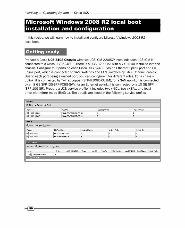
Getting readyPrepare a Cisco UCS 5108 Chassis with two UCS IOM 2208XP installed; each UCS IOM is connected to a Cisco UCS 6248UP. There is a UCS B200 M3 with a VIC 1240 installed into the chassis. Confi gure four ports on each Cisco UCS 6248UP as an Ethernet uplink port and FC uplink port, which is connected to SAN Switches and LAN Switches by Fibre Channel cables. Due to each port being a unifi ed port, you can confi gure it for different roles. For a chassis uplink, it is connected by Twinax copper (SFP-H10GB-CU1M); for a SAN uplink, it is connected by an 8 GB SFP (DS-SFP-FC8G-SW); for an Ethernet uplink, it is connected by a 10 GB SFP (SFP-10G-SR). Prepare a UCS service profi le, it includes two vNICs, two vHBAs, and local drive with mirror mode (RAID 1). The details are listed in the following service profi le:

Chapter 3
91
How to do it…In this recipe, we will learn how to prepare a boot policy on the UCS for Microsoft Server 2008 local boot installation.
Assume that there are two 300 GB SAS local disks and a LSI MegaRAID SAS 2004 installed on a Blade Server and you have prepared a service profi le WIN08_Local_Boot, which is defi ned as two vNICs and two vHBAs:
1. Log in to a UCS Manager; click on the Servers tab in the navigation pane and right-click on Local Disk Confi g Policies and select Create Local Disk Confi guration Policy.
2. Now, defi ne the local disk policy in Raid 1. Input the Name of the local disk as localdisk_raid1 and Mode in RAID 1 Mirrored:
3. Go to the Servers tab and select a service profi le WIN08_Local_Boot, select Change Local Disk Confi guration Policy on Storage tab and select the localdisk_raid1 on the Select the Local Disk Confi guration Policy menu:
Installing an Operating System on Cisco UCS
92
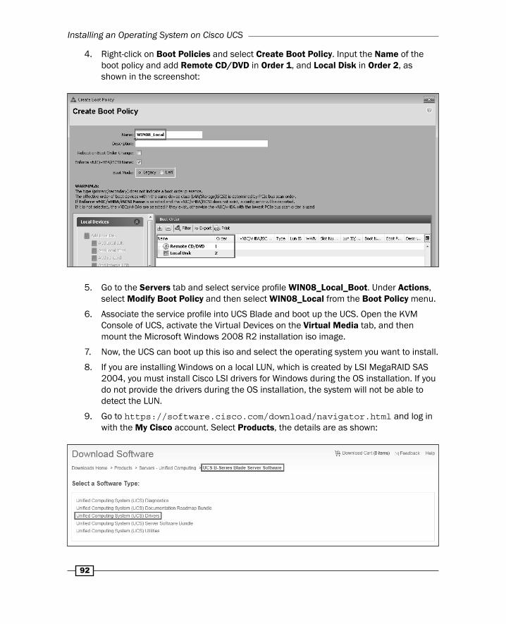
4. Right-click on Boot Policies and select Create Boot Policy. Input the Name of the boot policy and add Remote CD/DVD in Order 1, and Local Disk in Order 2, as shown in the screenshot:
5. Go to the Servers tab and select service profi le WIN08_Local_Boot. Under Actions, select Modify Boot Policy and then select WIN08_Local from the Boot Policy menu.
6. Associate the service profi le into UCS Blade and boot up the UCS. Open the KVM Console of UCS, activate the Virtual Devices on the Virtual Media tab, and then mount the Microsoft Windows 2008 R2 installation iso image.
7. Now, the UCS can boot up this iso and select the operating system you want to install.
8. If you are installing Windows on a local LUN, which is created by LSI MegaRAID SAS 2004, you must install Cisco LSI drivers for Windows during the OS installation. If you do not provide the drivers during the OS installation, the system will not be able to detect the LUN.
9. Go to https://software.cisco.com/download/navigator.html and log in with the My Cisco account. Select Products, the details are as shown:

Chapter 3
93
Note: Access to the download UCS driver is limited to users with an active Technical Support contract with Cisco.
10. Select 2.2(5b) and download ucs-bxxx-drivers.2.2.5b.iso:
11. Load the LSI driver during the OS installation.
You need to un-mount Microsoft Windows 2008 installation iso first and mount the UCS driver iso to load the driver into UCS.
12. After loading the driver, you can see the local drive and click on Next to install the OS.
13. It starts to install Microsoft Windows 2008 and will reboot automatically when it fi nishes the installation.
How it works…In this recipe, we will learn how to verify that Microsoft Windows 2008 can local boot successfully and install the Cisco VIC driver into Windows 2008 R2.
Follow these steps to local boot the Windows 2008 and install the Cisco VIC driver into Windows 2008 R2:
1. After booting up Windows 2008 R2, you wont be able to view the Storage adapter and Network adapter that were listed in the Device Manager.
2. Mount the ucs-bxxx-drivers.2.2.5b.iso and install the Cisco VIC driver into Windows 2008 R2 by Cisco VIO Installer.
Installing an Operating System on Cisco UCS
94
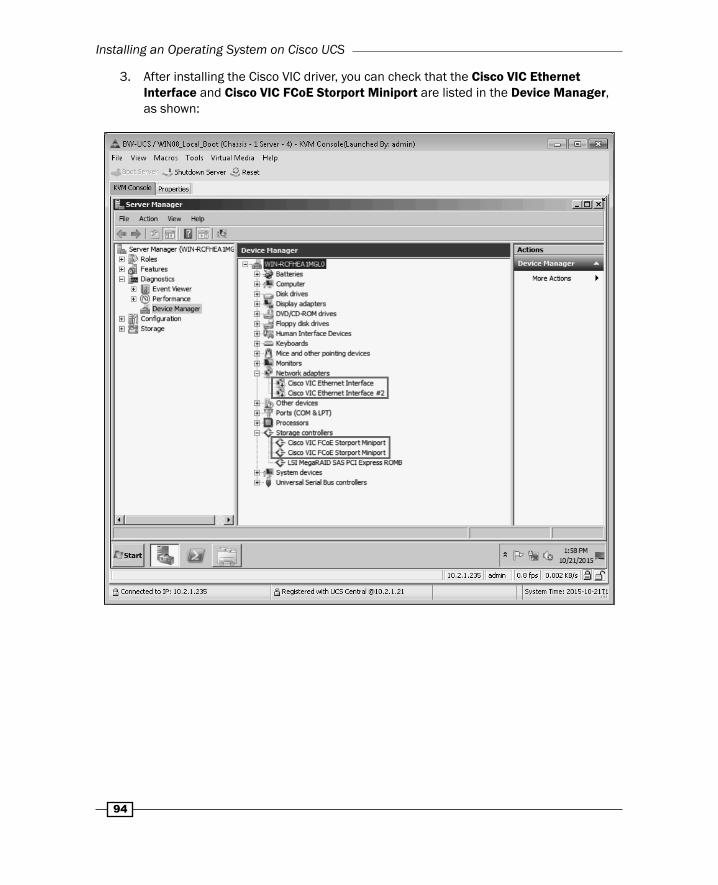
3. After installing the Cisco VIC driver, you can check that the Cisco VIC Ethernet Interface and Cisco VIC FCoE Storport Miniport are listed in the Device Manager, as shown:
Chapter 3
95
Microsoft Windows 2012 R2 local boot installation and confi guration
In this recipe, we will learn how to install and confi gure Microsoft Windows 2012 R2 local boot.
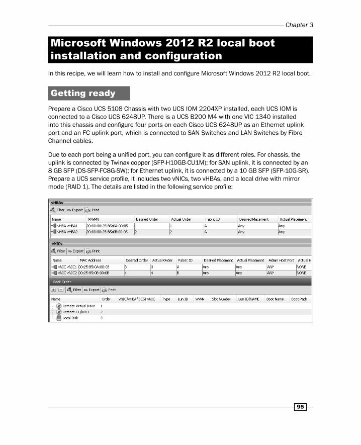
Getting readyPrepare a Cisco UCS 5108 Chassis with two UCS IOM 2204XP installed, each UCS IOM is connected to a Cisco UCS 6248UP. There is a UCS B200 M4 with one VIC 1340 installed into this chassis and confi gure four ports on each Cisco UCS 6248UP as an Ethernet uplink port and an FC uplink port, which is connected to SAN Switches and LAN Switches by Fibre Channel cables.
Due to each port being a unifi ed port, you can confi gure it as different roles. For chassis, the uplink is connected by Twinax copper (SFP-H10GB-CU1M); for SAN uplink, it is connected by an 8 GB SFP (DS-SFP-FC8G-SW); for Ethernet uplink, it is connected by a 10 GB SFP (SFP-10G-SR). Prepare a UCS service profi le, it includes two vNICs, two vHBAs, and a local drive with mirror mode (RAID 1). The details are listed in the following service profi le:

Installing an Operating System on Cisco UCS
96
How to do it…In this recipe, we will learn how to prepare a boot policy on UCS for Microsoft Server 2012 local boot installation.
Assume that there are two 300 GB SAS local disks and LSI MegaRAID SAS 2004 installed on Blade Server and you have prepared one service profi le WIN12_Local_Boot, which is defi ned by two vNICs and two vHBAs:
1. Log in to UCS Manager, click on the Servers tab in the navigation pane, and then right-click on Local Disk Confi g Policies and select Create Local Disk Confi guration Policy.
2. Now defi ne the local disk policy in Raid 1. Input the Name of the local disk as localdisk_raid1 and Mode in RAID 1 Mirrored.
3. Go to the Servers tab and select service profi le WIN12_Local_Boot, select Change Local Disk Confi guration Policy on the Storage tab. Select the localdisk_raid1 on the Select the Local Disk Confi guration Policy menu:
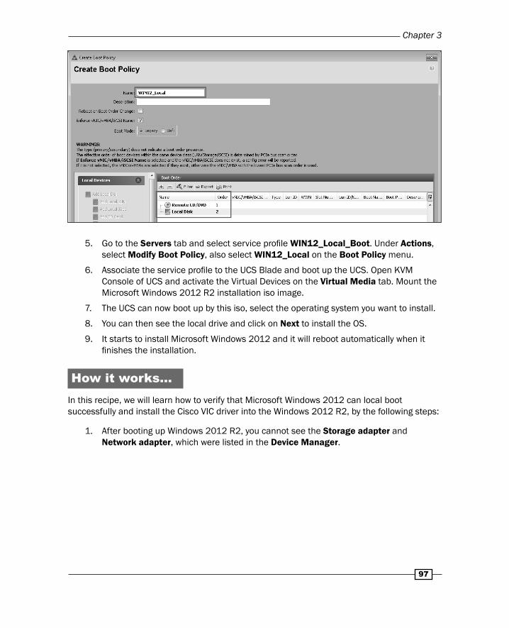
4. Right-click on Boot Policies and select Create Boot Policy. Input the Name of the boot policy and add Remote CD/DVD in Order 1, and Local Disk in Order 2:
Chapter 3
97
5. Go to the Servers tab and select service profi le WIN12_Local_Boot. Under Actions, select Modify Boot Policy, also select WIN12_Local on the Boot Policy menu.
6. Associate the service profi le to the UCS Blade and boot up the UCS. Open KVM Console of UCS and activate the Virtual Devices on the Virtual Media tab. Mount the Microsoft Windows 2012 R2 installation iso image.
7. The UCS can now boot up by this iso, select the operating system you want to install.
8. You can then see the local drive and click on Next to install the OS.
9. It starts to install Microsoft Windows 2012 and it will reboot automatically when it fi nishes the installation.
How it works…In this recipe, we will learn how to verify that Microsoft Windows 2012 can local boot successfully and install the Cisco VIC driver into the Windows 2012 R2, by the following steps:
1. After booting up Windows 2012 R2, you cannot see the Storage adapter and Network adapter, which were listed in the Device Manager.
Installing an Operating System on Cisco UCS
98
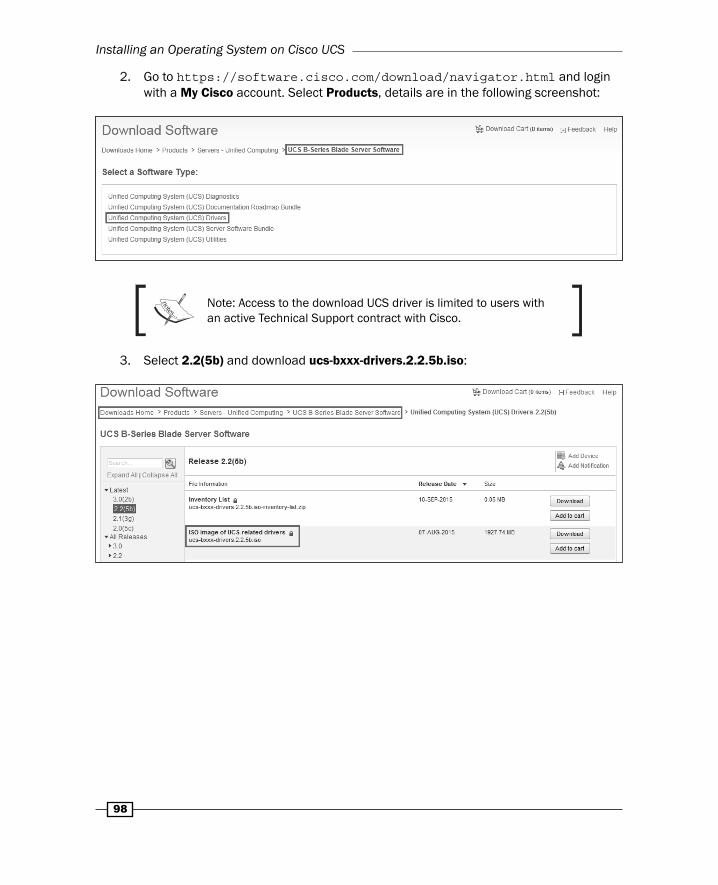
2. Go to https://software.cisco.com/download/navigator.html and login with a My Cisco account. Select Products, details are in the following screenshot:
Note: Access to the download UCS driver is limited to users with an active Technical Support contract with Cisco.
3. Select 2.2(5b) and download ucs-bxxx-drivers.2.2.5b.iso:

Chapter 3
99
4. Mount ucs-bxxx-drivers.2.2.5b.iso by virtual media and install Cisco VIC driver into Windows 2012 R2 by Cisco VIO Installer.
5. After installing Cisco VIC driver, you can check that the Cisco VIC Ethernet Interface and Cisco VIC-FCoE Storport Miniport are listed in the Device Manager:

Installing an Operating System on Cisco UCS
100
VMware vSphere 5.5 local boot installation and confi guration
In this recipe, we will learn how to install and confi gure VMware vSphere 5.5 local boot.
Getting readyPrepare a Cisco UCS 5108 Chassis with two UCS IOM 2208XP installed, each UCS IOM is connected to a Cisco UCS 6428UP. There is a UCS B200 M4 with a VIC 1340 installed into this chassis and confi gure four ports on each Cisco UCS 6428UP as an Ethernet uplink port and an FC uplink port, which is connected to SAN Switches and LAN Switches by Fibre Channel cables. Due to each port being a unifi ed port, you can confi gure it for different roles; for chassis uplink, it is connected by Twinax copper (SFP-H10GB-CU1M); for SAN uplink, it is connected by 8 GB SFP (DS-SFP-FC8G-SW); for Ethernet uplink, it is connected by a 10 GB SFP (SFP-10G-SR) and prepare a UCS service profi le. It includes two vNICs, two vHBAs, and a local drive with a mirror mode (RAID 1). The detail is listed in the following service profi le screenshot:
How to do it…In this recipe, we will learn how to prepare a boot policy on UCS for VMware vSphere 5.5 local boot installation.
Assume there are two 300 GB SAS local disks and a LSI MegaRAID SAS 2004 installed on a Blade Server, and you have prepared one service profi le ESXi5.5_Local_Boot, which is defi ned by two vNICs and two vHBAs:
Chapter 3
101
1. Log in to UCS Manager, click on the Servers tab in the navigation pane and right-click on Local Disk Confi g Policies, and select Create Local Disk Confi guration Policy.
2. Now, defi ne the local disk policy in Raid 1. Input the Name of local disk as localdisk_raid1 and Mode in RAID 1 Mirrored.
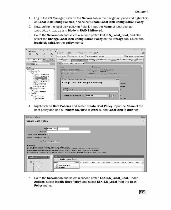
3. Go to the Servers tab and select a service profi le ESXi5.5_Local_Boot, and also select the Change Local Disk Confi guration Policy on the Storage tab. Select the localdisk_raid1 on the policy menu:
4. Right-click on Boot Policies and select Create Boot Policy. Input the Name of the boot policy and add a Remote CD/DVD in Order 1, and Local Disk in Order 2:
5. Go to the Servers tab and select a service profi le ESXi5.5_Local_Boot. Under Actions, select Modify Boot Policy, and select ESXi5.5_Local from the Boot Policy menu.
Installing an Operating System on Cisco UCS
102
6. Associate service profi le into the UCS Blade and boot up the UCS. Open the KVM Console of UCS, you can see the Active Virtual Devices on Virtual Media tab. Mount the VMware vSphere 5.5 installation iso image.
According to Cisco best practice, install ESXi using Cisco Custom Image for ESXi 5.5 iso.
7. The UCS can boot up by this iso, start installing ESXi 5.5.
8. Now, you can see the local drive and click on Next to install the OS.
9. It starts to install ESXi 5.5 and will reboot automatically when it fi nishes the installation.
How it works…In this recipe, we will learn how to verify that VMware vSphere 5.5 can local boot successfully.
Assume that vSphere 5.5 has already confi gured the management IP:
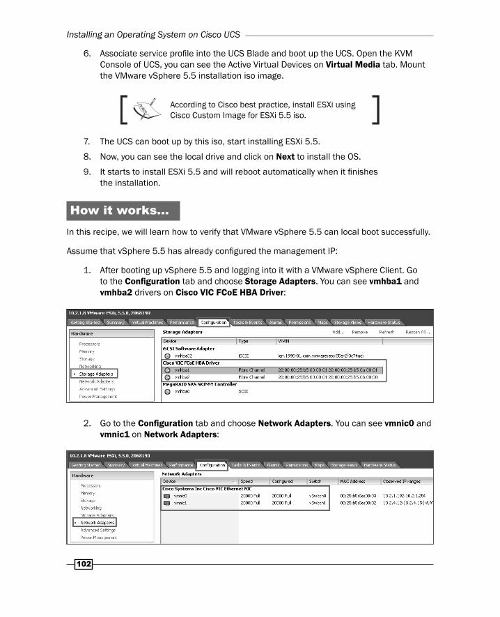
1. After booting up vSphere 5.5 and logging into it with a VMware vSphere Client. Go to the Confi guration tab and choose Storage Adapters. You can see vmhba1 and vmhba2 drivers on Cisco VIC FCoE HBA Driver:
2. Go to the Confi guration tab and choose Network Adapters. You can see vmnic0 and vmnic1 on Network Adapters:
Chapter 3
103
VMware vSphere SAN boot confi guration in EMC Storage
In this recipe, we will learn how to install and confi gure VMware vSphere 5.5 SAN boot in EMC Storage.
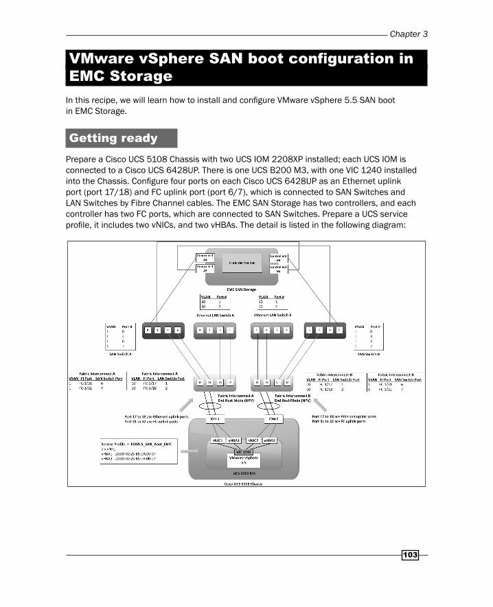
Getting readyPrepare a Cisco UCS 5108 Chassis with two UCS IOM 2208XP installed; each UCS IOM is connected to a Cisco UCS 6428UP. There is one UCS B200 M3, with one VIC 1240 installed into the Chassis. Confi gure four ports on each Cisco UCS 6428UP as an Ethernet uplink port (port 17/18) and FC uplink port (port 6/7), which is connected to SAN Switches and LAN Switches by Fibre Channel cables. The EMC SAN Storage has two controllers, and each controller has two FC ports, which are connected to SAN Switches. Prepare a UCS service profi le, it includes two vNICs, and two vHBAs. The detail is listed in the following diagram:
Installing an Operating System on Cisco UCS
104
How to do it…In this recipe, we will learn how to prepare a boot policy on UCS for VMware ESXi 5.5 SAN boot installation. Assume that the name of the service profi le is ESXi5.5_SAN_Boot_EMC and the EMC SAN Storage is CLARiiON CX4-240.
Follow these steps to prepare a boot policy on UCS for VMware ESXi 5.5 SAN boot installation:
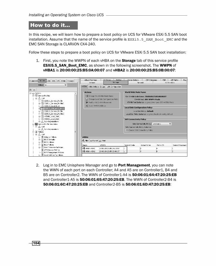
1. First, you note the WWPN of each vHBA on the Storage tab of this service profi le ESXi5.5_SAN_Boot_EMC, as shown in the following screenshot. The WWPN of vHBA1 is 20:00:00:25:B5:0A:00:07 and vHBA2 is 20:00:00:25:B5:0B:00:07:
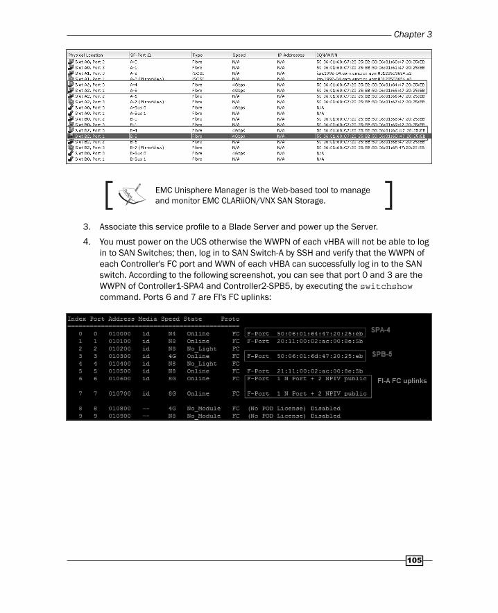
2. Log in to EMC Unisphere Manager and go to Port Management, you can note the WWN of each port on each Controller; A4 and A5 are on Controller1, B4 and B5 are on Controller2. The WWN of Controller1-A4 is 50:06:01:64:47:20:25:EB and Controller1-A5 is 50:06:01:65:47:20:25:EB. The WWN of Controller2-B4 is 50:06:01:6C:47:20:25:EB and Controller2-B5 is 50:06:01:6D:47:20:25:EB:
Chapter 3
105
EMC Unisphere Manager is the Web-based tool to manage and monitor EMC CLARiiON/VNX SAN Storage.
3. Associate this service profi le to a Blade Server and power up the Server.
4. You must power on the UCS otherwise the WWPN of each vHBA will not be able to log in to SAN Switches; then, log in to SAN Switch-A by SSH and verify that the WWPN of each Controller's FC port and WWN of each vHBA can successfully log in to the SAN switch. According to the following screenshot, you can see that port 0 and 3 are the WWPN of Controller1-SPA4 and Controller2-SPB5, by executing the switchshow command. Ports 6 and 7 are FI's FC uplinks:
Installing an Operating System on Cisco UCS
106
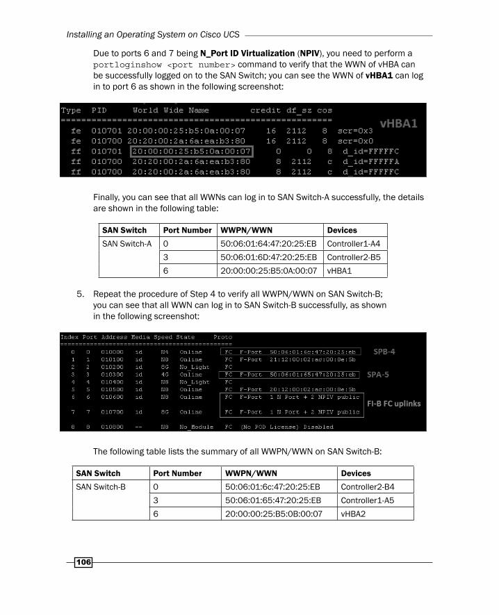
Due to ports 6 and 7 being N_Port ID Virtualization (NPIV), you need to perform a portloginshow <port number> command to verify that the WWN of vHBA can be successfully logged on to the SAN Switch; you can see the WWN of vHBA1 can log in to port 6 as shown in the following screenshot:
Finally, you can see that all WWNs can log in to SAN Switch-A successfully, the details are shown in the following table:
SAN Switch Port Number WWPN/WWN Devices
SAN Switch-A 0 50:06:01:64:47:20:25:EB Controller1-A4
3 50:06:01:6D:47:20:25:EB Controller2-B5
6 20:00:00:25:B5:0A:00:07 vHBA1
5. Repeat the procedure of Step 4 to verify all WWPN/WWN on SAN Switch-B; you can see that all WWN can log in to SAN Switch-B successfully, as shown in the following screenshot:
The following table lists the summary of all WWPN/WWN on SAN Switch-B:
SAN Switch Port Number WWPN/WWN Devices
SAN Switch-B 0 50:06:01:6c:47:20:25:EB Controller2-B4
3 50:06:01:65:47:20:25:EB Controller1-A5
6 20:00:00:25:B5:0B:00:07 vHBA2
Chapter 3
107
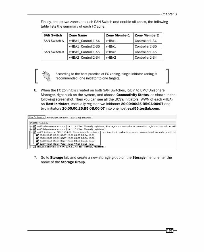
Finally, create two zones on each SAN Switch and enable all zones, the following table lists the summary of each FC zone:
SAN Switch Zone Name Zone Member1 Zone Member2
SAN Switch-A vHBA1_Controll1-A4 vHBA1- Controller1-A4
vHBA1_Controll2-B5 vHBA1 Controller2-B5
SAN Switch-B vHBA2_Controll1-A5 vHBA2 Controller1-A5
vHBA2_Controll2-B4 vHBA2 Controller2-B4
According to the best practice of FC zoning, single initiator zoning is recommended (one initiator to one target).
6. When the FC zoning is created o n both SAN Switches, log in to EMC Unisphere Manager, right-click on the system, and choose Connectivity Status, as shown in the following screenshot. Then you can see all the UCS's initiators (WWN of each vHBA) on Host Initiators, manually register two initiators 20:00:00:25:B5:0A:00:07 and two initiators 20:00:00:25:B5:0B:00:07 into one host esxi55.testlab.com:
7. Go to Storage tab and create a new storage group on the Storage menu, enter the name of the Storage Group.
Installing an Operating System on Cisco UCS
108
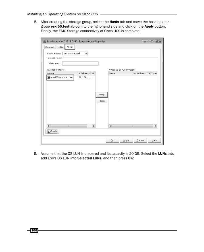
8. After creating the storage group, select the Hosts tab and move the host initiator group esxi55.testlab.com to the right-hand side and click on the Apply button. Finally, the EMC Storage connectivity of Cisco UCS is complete:
9. Assume that the OS LUN is prepared and its capacity is 20 GB. Select the LUNs tab, add ESX's OS LUN into Selected LUNs, and then press OK:

Chapter 3
109
10. Go to UCS Manager, right-click on Boot Policies and select Create Boot Policy on Servers tab:
11. Input the Name of the boot policy and move Remote CD/DVD in Order 1, and SAN Boot in Order 2. Each SAN boot has two boot targets, you need to input the vHBA name and WWN of the SAN target. The name of vHBA must be same as the name of the UCS's vHBA, otherwise the boot target cannot work.

Installing an Operating System on Cisco UCS
110
The table lists the summary of the SAN boot target:
SAN boot
vHBA SAN target Target WWN Storage port
SAN boot
vHBA1 Primary 50:06:01:64:47:20:25:EB Controller1-A4
Secondary 50:06:01:6D:47:20:25:EB Controller2-B5
vHBA2 Primary 50:06:01:6c:47:20:25:EB Controller2-B4
Secondary 50:06:01:65:47:20:25:EB Controller1-A5
12. Go to the Servers tab and select service profi le ESXi5.5_SAN_Boot_EMC, and select Modify Boot Policy on Boot Order tab. Select ESXi5.5_EMC on the Boot Policy menu.
13. Power down UCS and re-associate this service profi le into UCS again. Then, power on UCS and open the KVM Console, you can see four paths appear during UCS boot up, these are the WWN of the SAN boot target:
Chapter 3
111
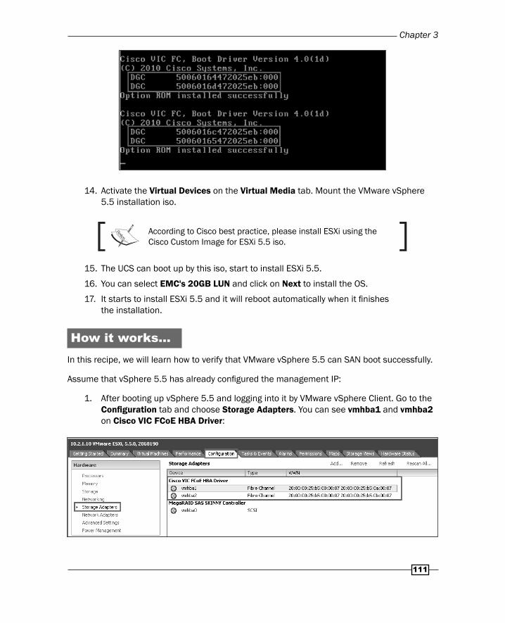
14. Activate the Virtual Devices on the Virtual Media tab. Mount the VMware vSphere 5.5 installation iso.
According to Cisco best practice, please install ESXi using the Cisco Custom Image for ESXi 5.5 iso.
15. The UCS can boot up by this iso, start to install ESXi 5.5.
16. You can select EMC's 20GB LUN and click on Next to install the OS.
17. It starts to install ESXi 5.5 and it will reboot automatically when it fi nishes the installation.
How it works…In this recipe, we will learn how to verify that VMware vSphere 5.5 can SAN boot successfully.
Assume that vSphere 5.5 has already confi gured the management IP:
1. After booting up vSphere 5.5 and logging into it by VMware vSphere Client. Go to the Confi guration tab and choose Storage Adapters. You can see vmhba1 and vmhba2 on Cisco VIC FCoE HBA Driver:
Installing an Operating System on Cisco UCS
112
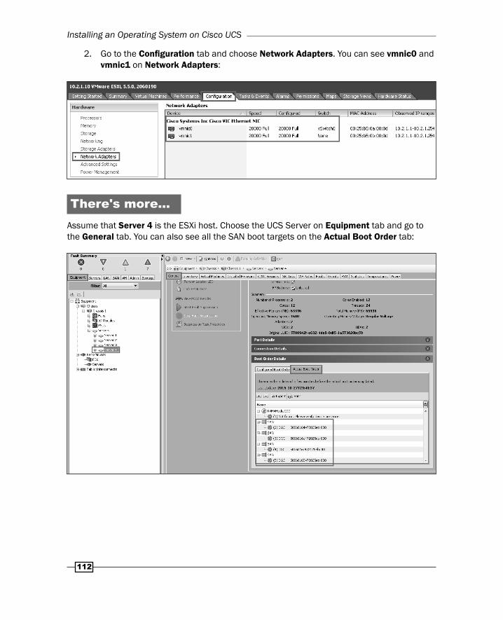
2. Go to the Confi guration tab and choose Network Adapters. You can see vmnic0 and vmnic1 on Network Adapters:
There's more…Assume that Server 4 is the ESXi host. Choose the UCS Server on Equipment tab and go to the General tab. You can also see all the SAN boot targets on the Actual Boot Order tab:
Chapter 3
113
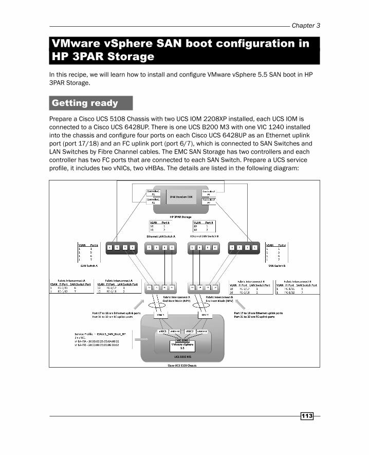
VMware vSphere SAN boot confi guration in HP 3PAR Storage
In this recipe, we will learn how to install and confi gure VMware vSphere 5.5 SAN boot in HP 3PAR Storage.
Getting readyPrepare a Cisco UCS 5108 Chassis with two UCS IOM 2208XP installed, each UCS IOM is connected to a Cisco UCS 6428UP. There is one UCS B200 M3 with one VIC 1240 installed into the chassis and confi gure four ports on each Cisco UCS 6428UP as an Ethernet uplink port (port 17/18) and an FC uplink port (port 6/7), which is connected to SAN Switches and LAN Switches by Fibre Channel cables. The EMC SAN Storage has two controllers and each controller has two FC ports that are connected to each SAN Switch. Prepare a UCS service profi le, it includes two vNICs, two vHBAs. The details are listed in the following diagram:
Installing an Operating System on Cisco UCS
114
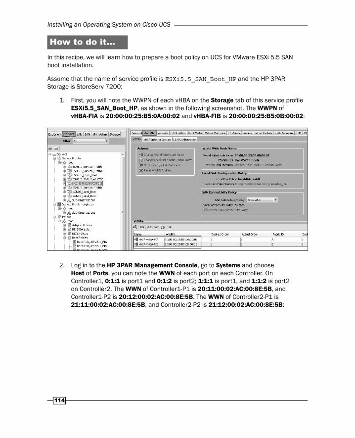
How to do it…In this recipe, we will learn how to prepare a boot policy on UCS for VMware ESXi 5.5 SAN boot installation.
Assume that the name of service profi le is ESXi5.5_SAN_Boot_HP and the HP 3PAR Storage is StoreServ 7200:
1. First, you will note the WWPN of each vHBA on the Storage tab of this service profi le ESXi5.5_SAN_Boot_HP, as shown in the following screenshot. The WWPN of vHBA-FIA is 20:00:00:25:B5:0A:00:02 and vHBA-FIB is 20:00:00:25:B5:0B:00:02:
2. Log in to the HP 3PAR Management Console, go to Systems and choose Host of Ports, you can note the WWN of each port on each Controller. On Controller1, 0:1:1 is port1 and 0:1:2 is port2; 1:1:1 is port1, and 1:1:2 is port2 on Controller2. The WWN of Controller1-P1 is 20:11:00:02:AC:00:8E:5B, and Controller1-P2 is 20:12:00:02:AC:00:8E:5B. The WWN of Controller2-P1 is 21:11:00:02:AC:00:8E:5B, and Controller2-P2 is 21:12:00:02:AC:00:8E:5B:

Chapter 3
115
3PAR Management Console is a management tool that is used to manage HP 3PAR Storage.
3. Associate this service profi le into UCS and then power on the UCS.
4. You must power on the UCS, otherwise the WWPN of each vHBA cannot log in to each SAN Switches. Then log in to SAN Switch-A by SSH and verify that the WWPN of each 3PAR Controller's FC port and WWN of each vHBA can successfully log on to the SAN switch. According to the following screenshot, you can see that port 1 and 5 are the WWPN of Controller1-P1 and Controller2-P1 by executing the switchshow command. Ports 6 and 7 are FI's FC uplinks:
Installing an Operating System on Cisco UCS
116
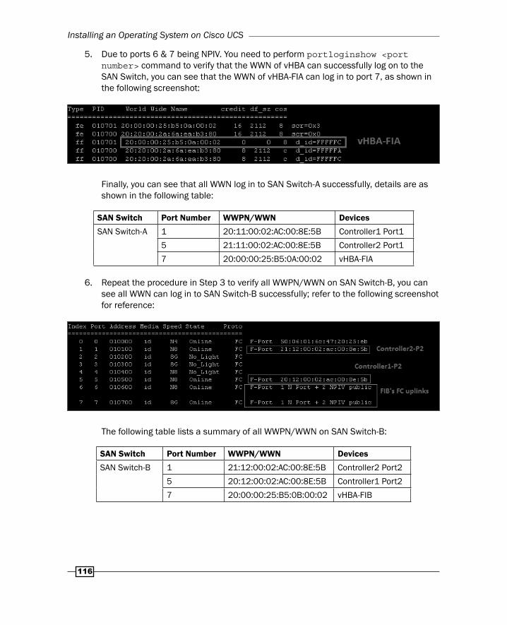
5. Due to ports 6 & 7 being NPIV. You need to perform portloginshow <port number> command to verify that the WWN of vHBA can successfully log on to the SAN Switch, you can see that the WWN of vHBA-FIA can log in to port 7, as shown in the following screenshot:
Finally, you can see that all WWN log in to SAN Switch-A successfully, details are as shown in the following table:
SAN Switch Port Number WWPN/WWN Devices
SAN Switch-A 1 20:11:00:02:AC:00:8E:5B Controller1 Port1
5 21:11:00:02:AC:00:8E:5B Controller2 Port1
7 20:00:00:25:B5:0A:00:02 vHBA-FIA
6. Repeat the procedure in Step 3 to verify all WWPN/WWN on SAN Switch-B, you can see all WWN can log in to SAN Switch-B successfully; refer to the following screenshot for reference:
The following table lists a summary of all WWPN/WWN on SAN Switch-B:
SAN Switch Port Number WWPN/WWN Devices
SAN Switch-B 1 21:12:00:02:AC:00:8E:5B Controller2 Port2
5 20:12:00:02:AC:00:8E:5B Controller1 Port2
7 20:00:00:25:B5:0B:00:02 vHBA-FIB
Chapter 3
117
Finally, create two zones on each SAN Switch and enable all zones, the following table lists the summary of each FC zone:
SAN Switch Zone Name Zone Member1 Zone Member2
SAN Switch-A vHBA-FIA_Controll1-P1 vHBA-FIA Controller1 Port1
vHBA-FIA_Controll1-P2 vHBA-FIA Controller2 Port1
SAN Switch-B vHBA-FIB_Controll1-P2 vHBA-FIB Controller1 Port2
vHBA-FIB_Controll1-P2 vHBA-FIB Controller2 Port2
According to the best practice of FC zoning, single initiator zoning is recommended (one initiator to one target).
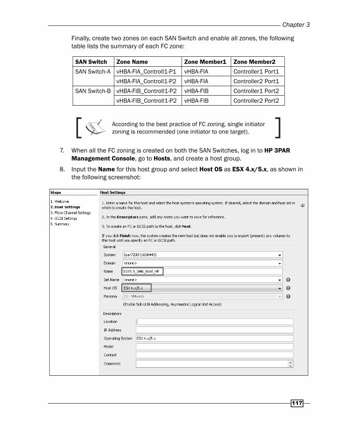
7. When all the FC zoning is created on both the SAN Switches, log in to HP 3PAR Management Console, go to Hosts, and create a host group.
8. Input the Name for this host group and select Host OS as ESX 4.x/5.x, as shown in the following screenshot:

Installing an Operating System on Cisco UCS
118
9. Move all the Available WWNs that are related to UCS's vHBA-FIA and vHBA-FIB, that is, 20:00:00:25:B5:0A:00:02 and 20:00:00:25:B5:0B:00:02, to Assigned WWNs, as shown in the following screenshot:
It has four WWNs available due to the fact that it has two zones for each vHBA on each SAN Switch.
10. Assume that the ESXi system volume is 10 GB. After creating the host group, right-click on the menu and select Export Volume to assign this volume to the host group on the Volume menu.
11. Go to the UCS Manager, right-click on Boot Policies and select Create Boot Policy on the Servers tab.
Chapter 3
119
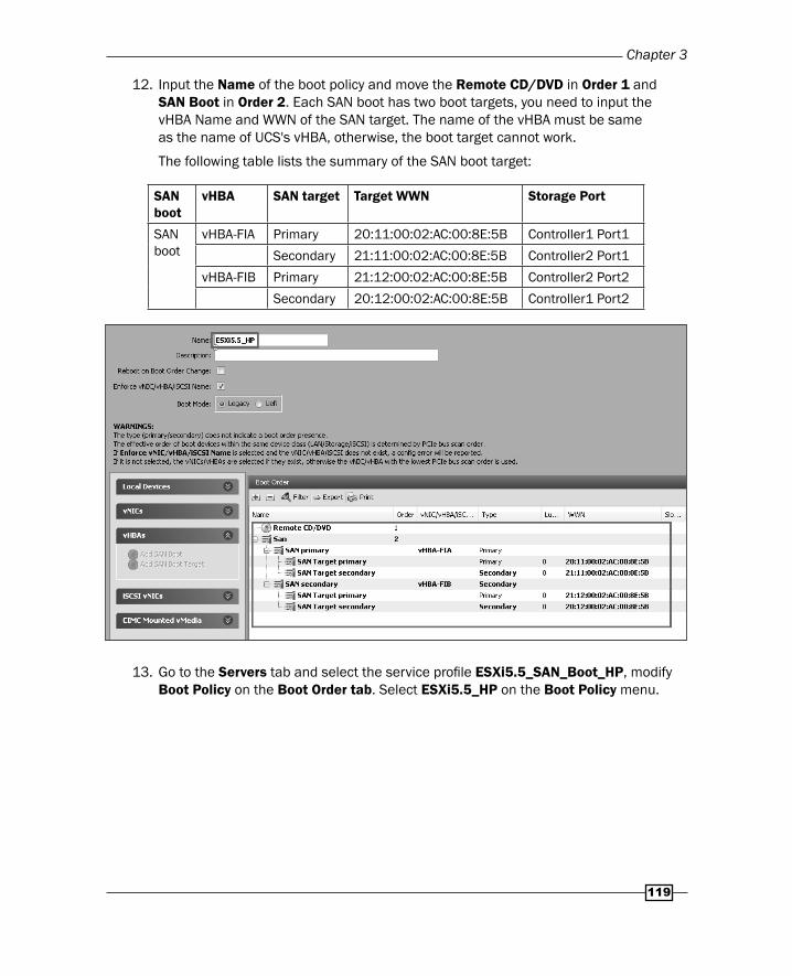
12. Input the Name of the boot policy and move the Remote CD/DVD in Order 1 and SAN Boot in Order 2. Each SAN boot has two boot targets, you need to input the vHBA Name and WWN of the SAN target. The name of the vHBA must be same as the name of UCS's vHBA, otherwise, the boot target cannot work.
The following table lists the summary of the SAN boot target:
SAN boot
vHBA SAN target Target WWN Storage Port
SAN boot
vHBA-FIA Primary 20:11:00:02:AC:00:8E:5B Controller1 Port1
Secondary 21:11:00:02:AC:00:8E:5B Controller2 Port1
vHBA-FIB Primary 21:12:00:02:AC:00:8E:5B Controller2 Port2
Secondary 20:12:00:02:AC:00:8E:5B Controller1 Port2
13. Go to the Servers tab and select the service profi le ESXi5.5_SAN_Boot_HP, modify Boot Policy on the Boot Order tab. Select ESXi5.5_HP on the Boot Policy menu.
Installing an Operating System on Cisco UCS
120
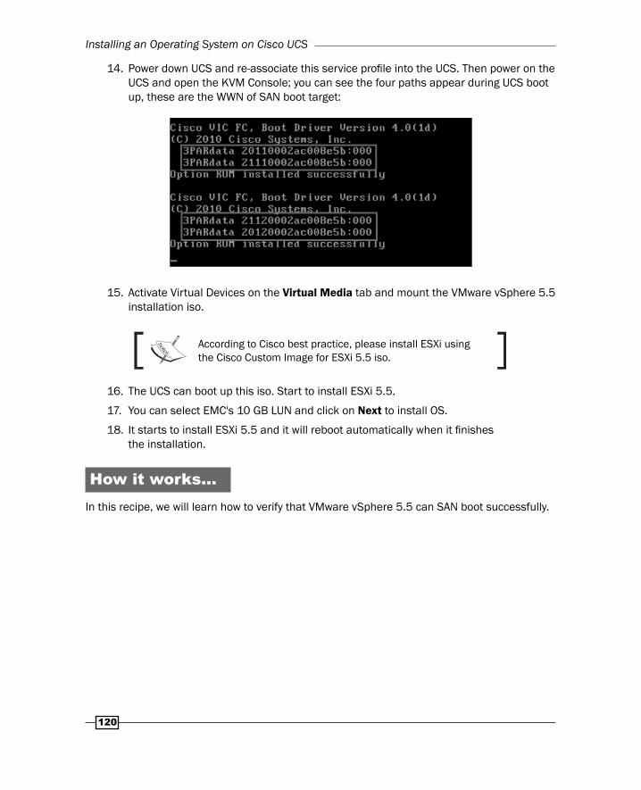
14. Power down UCS and re-associate this service profi le into the UCS. Then power on the UCS and open the KVM Console; you can see the four paths appear during UCS boot up, these are the WWN of SAN boot target:
15. Activate Virtual Devices on the Virtual Media tab and mount the VMware vSphere 5.5 installation iso.
According to Cisco best practice, please install ESXi using the Cisco Custom Image for ESXi 5.5 iso.
16. The UCS can boot up this iso. Start to install ESXi 5.5.
17. You can select EMC's 10 GB LUN and click on Next to install OS.
18. It starts to install ESXi 5.5 and it will reboot automatically when it fi nishes the installation.
How it works…In this recipe, we will learn how to verify that VMware vSphere 5.5 can SAN boot successfully.
Chapter 3
121
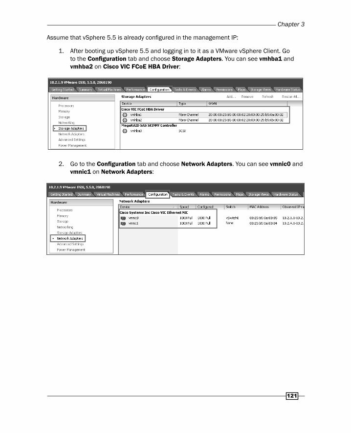
Assume that vSphere 5.5 is already confi gured in the management IP:
1. After booting up vSphere 5.5 and logging in to it as a VMware vSphere Client. Go to the Confi guration tab and choose Storage Adapters. You can see vmhba1 and vmhba2 on Cisco VIC FCoE HBA Driver:
2. Go to the Confi guration tab and choose Network Adapters. You can see vmnic0 and vmnic1 on Network Adapters:
Installing an Operating System on Cisco UCS
122
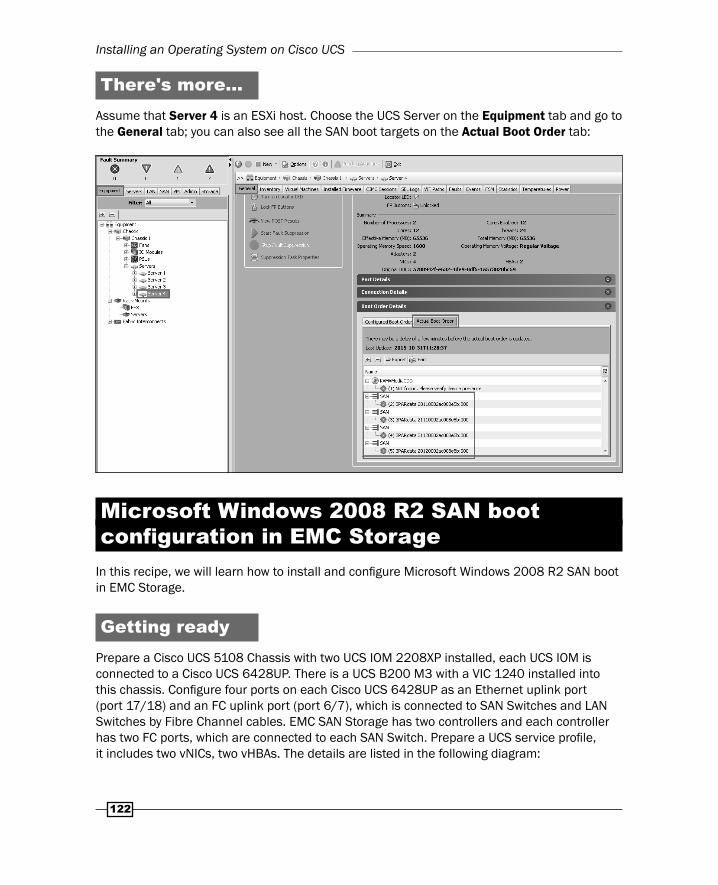
There's more…Assume that Server 4 is an ESXi host. Choose the UCS Server on the Equipment tab and go to the General tab; you can also see all the SAN boot targets on the Actual Boot Order tab:
Microsoft Windows 2008 R2 SAN boot confi guration in EMC Storage
In this recipe, we will learn how to install and confi gure Microsoft Windows 2008 R2 SAN boot in EMC Storage.
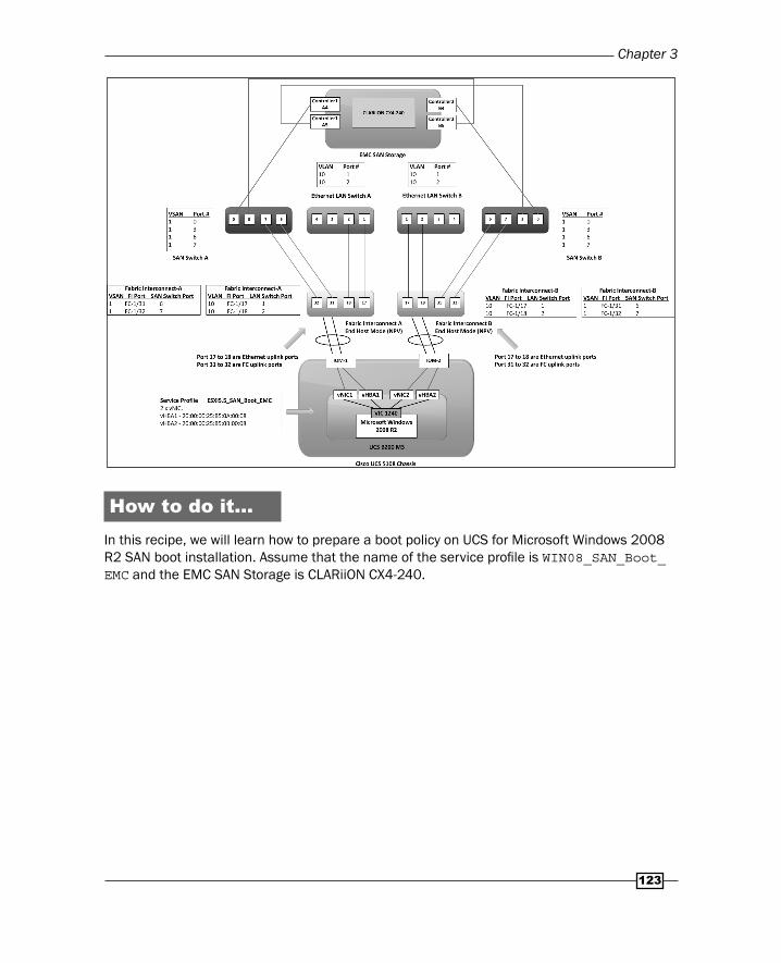
Getting readyPrepare a Cisco UCS 5108 Chassis with two UCS IOM 2208XP installed, each UCS IOM is connected to a Cisco UCS 6428UP. There is a UCS B200 M3 with a VIC 1240 installed into this chassis. Confi gure four ports on each Cisco UCS 6428UP as an Ethernet uplink port (port 17/18) and an FC uplink port (port 6/7), which is connected to SAN Switches and LAN Switches by Fibre Channel cables. EMC SAN Storage has two controllers and each controller has two FC ports, which are connected to each SAN Switch. Prepare a UCS service profi le, it includes two vNICs, two vHBAs. The details are listed in the following diagram:
Chapter 3
123
How to do it…In this recipe, we will learn how to prepare a boot policy on UCS for Microsoft Windows 2008 R2 SAN boot installation. Assume that the name of the service profi le is WIN08_SAN_Boot_EMC and the EMC SAN Storage is CLARiiON CX4-240.

Installing an Operating System on Cisco UCS
124
Follow these steps to install and confi gure Microsoft Windows 2008 R2 SAN boot in EMC Storage:
1. First, note the WWPN of each vHBA on the Storage tab of this service profi le WIN08_SAN_Boot_EMC as shown in the following screenshot. The WWPN of vHBA1 is 20:00:00:25:B5:0A:00:08 and vHBA2 is 20:00:00:25:B5:0B:00:08:
2. Log in to EMC Unisphere Manager and go to Port Management, you can note the WWN of each port on each Controller. A4 & A5 are on Controller1, with B4 and B5 on Controller2. The WWN of Controller1-A4 is 50:06:01:64:47:20:25:EB, and Controller1-A5 is 50:06:01:65:47:20:25:EB. The WWN of Controller2-B4 is 50:06:01:6C:47:20:25:EB, and Controller2-B5 is 50:06:01:6D:47:20:25:EB:
EMC Unisphere Manager is a Web-based tool to manage and monitor EMC CLARiiON/VNX SAN Storage.
Chapter 3
125
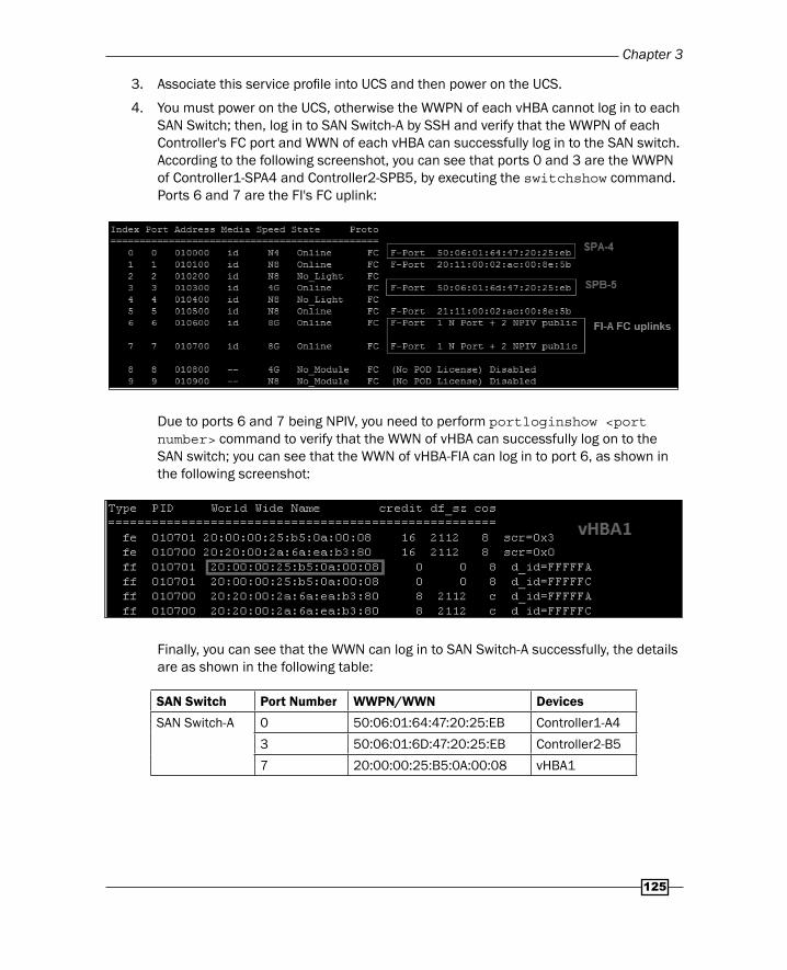
3. Associate this service profi le into UCS and then power on the UCS.
4. You must power on the UCS, otherwise the WWPN of each vHBA cannot log in to each SAN Switch; then, log in to SAN Switch-A by SSH and verify that the WWPN of each Controller's FC port and WWN of each vHBA can successfully log in to the SAN switch. According to the following screenshot, you can see that ports 0 and 3 are the WWPN of Controller1-SPA4 and Controller2-SPB5, by executing the switchshow command. Ports 6 and 7 are the FI's FC uplink:
Due to ports 6 and 7 being NPIV, you need to perform portloginshow <port number> command to verify that the WWN of vHBA can successfully log on to the SAN switch; you can see that the WWN of vHBA-FIA can log in to port 6, as shown in the following screenshot:
Finally, you can see that the WWN can log in to SAN Switch-A successfully, the details are as shown in the following table:
SAN Switch Port Number WWPN/WWN Devices
SAN Switch-A 0 50:06:01:64:47:20:25:EB Controller1-A4
3 50:06:01:6D:47:20:25:EB Controller2-B5
7 20:00:00:25:B5:0A:00:08 vHBA1
Installing an Operating System on Cisco UCS
126
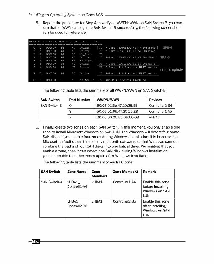
5. Repeat the procedure for Step 4 to verify all WWPN/WWN on SAN Switch-B, you can see that all WWN can log in to SAN Switch-B successfully, the following screenshot can be used for reference:
The following table lists the summary of all WWPN/WWN on SAN Switch-B:
SAN Switch Port Number WWPN/WWN Devices
SAN Switch-B 0 50:06:01:6c:47:20:25:EB Controller2-B4
3 50:06:01:65:47:20:25:EB Controller1-A5
7 20:00:00:25:B5:0B:00:08 vHBA2
6. Finally, create two zones on each SAN Switch. In this moment, you only enable one zone to install Microsoft Windows on SAN LUN. The Windows will detect four same SAN disks, if you enable four zones during Windows installation. It is because the Microsoft default doesn't install any multipath software, so that Windows cannot combine the paths of four SAN disks into one logical drive. We suggest that you enable a zone, then it can detect one SAN disk during Windows installation, you can enable the other zones again after Windows installation.
The following table lists the summary of each FC zone:
SAN Switch Zone Name Zone Member1
Zone Member2 Remark
SAN Switch-A vHBA1_Controll1-A4
vHBA1- Controller1-A4 Enable this zone before installing Windows on SAN LUN
vHBA1_Controll2-B5
vHBA1 Controller2-B5 Enable this zone after installing Windows on SAN LUN

Chapter 3
127
SAN Switch Zone Name Zone Member1
Zone Member2 Remark
SAN Switch-B vHBA2_Controll1-A5
vHBA2 Controller1-A5 Enable this zone after installing Windows on SAN LUN
vHBA2_Controll2-B4
vHBA2 Controller2-B4 Enable this zone after installing Windows on SAN LUN
According to the best practice of FC zoning, single initiator zoning is recommended (one initiator to one target).
7. After all FC zones are created on both SAN Switch and enabled one of four zones, then log in to EMC Unisphere Manager, right-click on the System, and choose a Connectivity Status. Since you only enable one zone on SAN Switch, you can see only one UCS's initiators (WWN of each vHBA) display on Host Initiators, you need to manually register one initiators, 20:00:00:25:B5:0A:00:08, into one host, win08.testlab.com:
8. Go to Storage and create a new storage group on the Storage menu and enter the name of the storage group.
Installing an Operating System on Cisco UCS
128
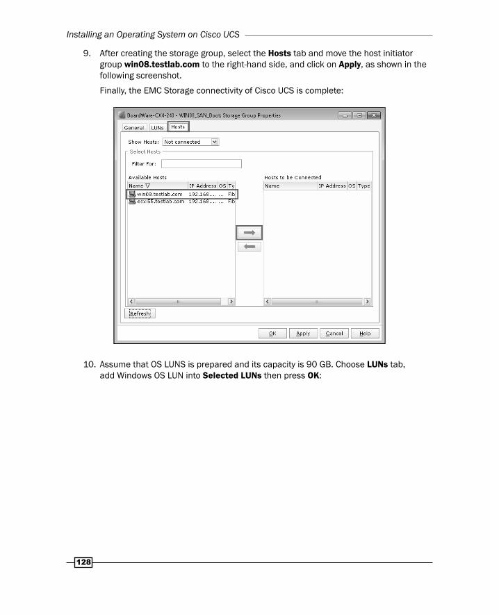
9. After creating the storage group, select the Hosts tab and move the host initiator group win08.testlab.com to the right-hand side, and click on Apply, as shown in the following screenshot.
Finally, the EMC Storage connectivity of Cisco UCS is complete:
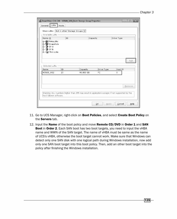
10. Assume that OS LUNS is prepared and its capacity is 90 GB. Choose LUNs tab, add Windows OS LUN into Selected LUNs then press OK:
Chapter 3
129
11. Go to UCS Manager, right-click on Boot Policies, and select Create Boot Policy on the Servers tab.
12. Input the Name of the boot policy and move Remote CD/DVD in Order 1 and SAN Boot in Order 2. Each SAN boot has two boot targets, you need to input the vHBA name and WWN of the SAN target. The name of vHBA must be same as the name of UCS's vHBA, otherwise the boot target cannot work. Make sure that Windows can detect only one SAN disk with one logical path during Windows installation, now add only one SAN boot target into this boot policy. Then, add an other boot target into the policy after fi nishing the Windows installation.

Installing an Operating System on Cisco UCS
130
The following table lists a summary of the SAN boot target:
SAN boot
vHBA SAN target Target WWN Storage Port
SAN boot
vHBA1 Primary 50:06:01:64:47:20:25:EB Controller1-A4
Secondary 50:06:01:6D:47:20:25:EB Controller2-B5
vHBA2 Primary 50:06:01:6c:47:20:25:EB Controller2-B4
Secondary 50:06:01:65:47:20:25:EB Controller1-A5
13. Go to the Servers tab and select service profi le WIN08_SAN_Boot_EMC and select Modify the Boot Policy on the Boot Order tab. Select WIN08_EMC on the Boot Policy menu.
14. Power down UCS and re-associate this service profi le into UCS again. Then power on UCS and open the KVM Console, you can see one path appearing during the UCS boot up; these are the WWN of SAN boot target:
Chapter 3
131
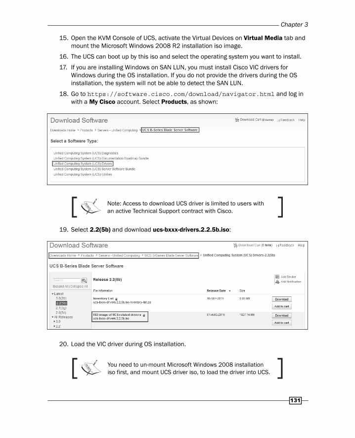
15. Open the KVM Console of UCS, activate the Virtual Devices on Virtual Media tab and mount the Microsoft Windows 2008 R2 installation iso image.
16. The UCS can boot up by this iso and select the operating system you want to install.
17. If you are installing Windows on SAN LUN, you must install Cisco VIC drivers for Windows during the OS installation. If you do not provide the drivers during the OS installation, the system will not be able to detect the SAN LUN.
18. Go to https://software.cisco.com/download/navigator.html and log in with a My Cisco account. Select Products, as shown:
Note: Access to download UCS driver is limited to users with an active Technical Support contract with Cisco.
19. Select 2.2(5b) and download ucs-bxxx-drivers.2.2.5b.iso:
20. Load the VIC driver during OS installation.
You need to un-mount Microsoft Windows 2008 installation iso first, and mount UCS driver iso, to load the driver into UCS.
Installing an Operating System on Cisco UCS
132
21. After loading the driver, you can see the local drive, click on Next to install OS.
22. It starts to install Microsoft Windows 2008 and it will reboot automatically when it fi nishes the installation.
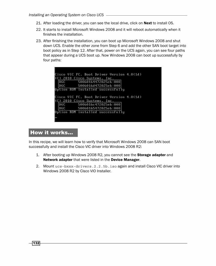
23. After fi nishing the installation, you can boot up Microsoft Windows 2008 and shut down UCS. Enable the other zone from Step 6 and add the other SAN boot target into boot policy as in Step 12. After that, power on the UCS again, you can see four paths that appear during a UCS boot up. Now Windows 2008 can boot up successfully by four paths:
How it works…In this recipe, we will learn how to verify that Microsoft Windows 2008 can SAN boot successfully and install the Cisco VIC driver into Windows 2008 R2:
1. After booting up Windows 2008 R2, you cannot see the Storage adapter and Network adapter that were listed in the Device Manager.
2. Mount ucs-bxxx-drivers.2.2.5b.iso again and install Cisco VIC driver into Windows 2008 R2 by Cisco VIO Installer.
Chapter 3
133
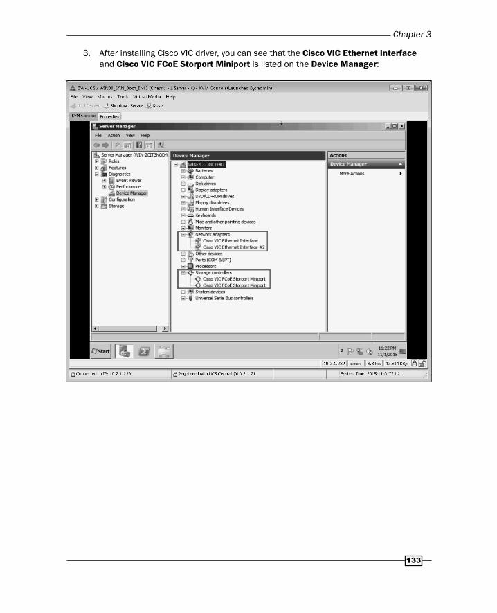
3. After installing Cisco VIC driver, you can see that the Cisco VIC Ethernet Interface and Cisco VIC FCoE Storport Miniport is listed on the Device Manager:
Installing an Operating System on Cisco UCS
134
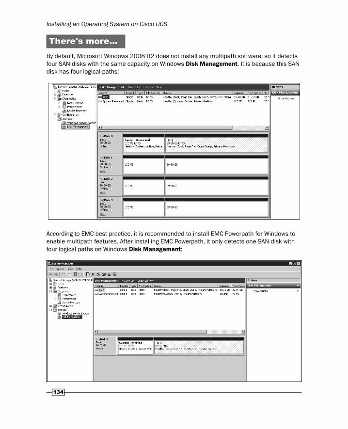
There's more…By default, Microsoft Windows 2008 R2 does not install any multipath software, so it detects four SAN disks with the same capacity on Windows Disk Management. It is because this SAN disk has four logical paths:
According to EMC best practice, it is recommended to install EMC Powerpath for Windows to enable multipath features. After installing EMC Powerpath, it only detects one SAN disk with four logical paths on Windows Disk Management:
Chapter 3
135
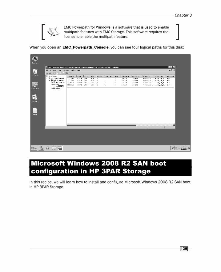
EMC Powerpath for Windows is a software that is used to enable multipath features with EMC Storage. This software requires the license to enable the multipath feature.
When you open an EMC_Powerpath_Console, you can see four logical paths for this disk:
Microsoft Windows 2008 R2 SAN boot confi guration in HP 3PAR Storage
In this recipe, we will learn how to install and confi gure Microsoft Windows 2008 R2 SAN boot in HP 3PAR Storage.
Installing an Operating System on Cisco UCS
136
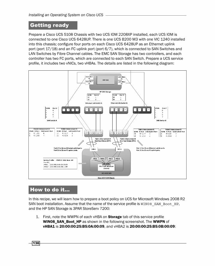
Getting readyPrepare a Cisco UCS 5108 Chassis with two UCS IOM 2208XP installed, each UCS IOM is connected to one Cisco UCS 6428UP. There is one UCS B200 M3 with one VIC 1240 installed into this chassis; confi gure four ports on each Cisco UCS 6428UP as an Ethernet uplink port (port 17/18) and an FC uplink port (port 6/7), which is connected to SAN Switches and LAN Switches by Fibre Channel cables. The EMC SAN Storage has two controllers, and each controller has two FC ports, which are connected to each SAN Switch. Prepare a UCS service profi le, it includes two vNICs, two vHBAs. The details are listed in the following diagram:
How to do it…In this recipe, we will learn how to prepare a boot policy on UCS for Microsoft Windows 2008 R2 SAN boot installation. Assume that the name of the service profi le is WIN08_SAN_Boot_HP, and the HP SAN Storage is 3PAR StoreServ 7200:
1. First, note the WWPN of each vHBA on Storage tab of this service profi le WIN08_SAN_Boot_HP as shown in the following screenshot. The WWPN of vHBA1 is 20:00:00:25:B5:0A:00:09, and vHBA2 is 20:00:00:25:B5:0B:00:09:
Chapter 3
137
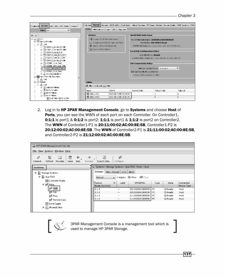
2. Log in to HP 3PAR Management Console, go to Systems and choose Host of Ports, you can see the WWN of each port on each Controller. On Controller1, 0:1:1 is port1 & 0:1:2 is port2; 1:1:1 is port1 & 1:1:2 is port2 on Controller2. The WWN of Controller1-P1 is 20:11:00:02:AC:00:8E:5B, Controller1-P2 is 20:12:00:02:AC:00:8E:5B. The WWN of Controller2-P1 is 21:11:00:02:AC:00:8E:5B, and Controller2-P2 is 21:12:00:02:AC:00:8E:5B:
3PAR Management Console is a management tool which is used to manage HP 3PAR Storage.
Installing an Operating System on Cisco UCS
138
3. Associate this service profi le into UCS and then power on the UCS.
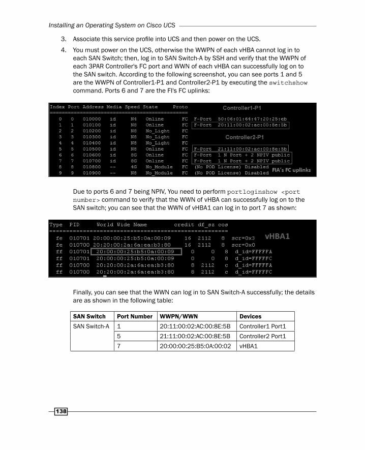
4. You must power on the UCS, otherwise the WWPN of each vHBA cannot log in to each SAN Switch; then, log in to SAN Switch-A by SSH and verify that the WWPN of each 3PAR Controller's FC port and WWN of each vHBA can successfully log on to the SAN switch. According to the following screenshot, you can see ports 1 and 5 are the WWPN of Controller1-P1 and Controller2-P1 by executing the switchshow command. Ports 6 and 7 are the FI's FC uplinks:
Due to ports 6 and 7 being NPIV, You need to perform portloginshow <port number> command to verify that the WWN of vHBA can successfully log on to the SAN switch; you can see that the WWN of vHBA1 can log in to port 7 as shown:
Finally, you can see that the WWN can log in to SAN Switch-A successfully; the details are as shown in the following table:
SAN Switch Port Number WWPN/WWN Devices
SAN Switch-A 1 20:11:00:02:AC:00:8E:5B Controller1 Port1
5 21:11:00:02:AC:00:8E:5B Controller2 Port1
7 20:00:00:25:B5:0A:00:02 vHBA1
Chapter 3
139
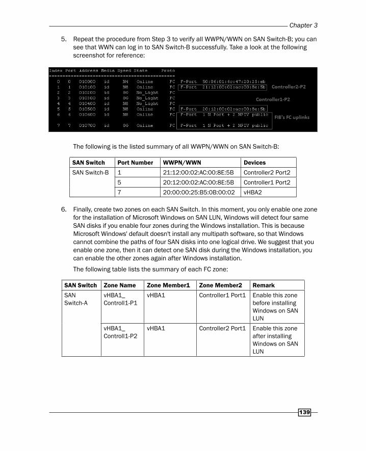
5. Repeat the procedure from Step 3 to verify all WWPN/WWN on SAN Switch-B; you can see that WWN can log in to SAN Switch-B successfully. Take a look at the following screenshot for reference:
The following is the listed summary of all WWPN/WWN on SAN Switch-B:
SAN Switch Port Number WWPN/WWN Devices
SAN Switch-B 1 21:12:00:02:AC:00:8E:5B Controller2 Port2
5 20:12:00:02:AC:00:8E:5B Controller1 Port2
7 20:00:00:25:B5:0B:00:02 vHBA2
6. Finally, create two zones on each SAN Switch. In this moment, you only enable one zone for the installation of Microsoft Windows on SAN LUN, Windows will detect four same SAN disks if you enable four zones during the Windows installation. This is because Microsoft Windows' default doesn't install any multipath software, so that Windows cannot combine the paths of four SAN disks into one logical drive. We suggest that you enable one zone, then it can detect one SAN disk during the Windows installation, you can enable the other zones again after Windows installation.
The following table lists the summary of each FC zone:
SAN Switch Zone Name Zone Member1 Zone Member2 Remark
SAN Switch-A
vHBA1_Controll1-P1
vHBA1 Controller1 Port1 Enable this zone before installing Windows on SAN LUN
vHBA1_Controll1-P2
vHBA1 Controller2 Port1 Enable this zone after installing Windows on SAN LUN
Installing an Operating System on Cisco UCS
140
SAN Switch Zone Name Zone Member1 Zone Member2 Remark
SAN Switch-B
vHBA2_Controll1-P2
vHBA2 Controller1 Port2 Enable this zone after installing Windows on SAN LUN
vHBA2_Controll1-P2
vHBA2 Controller2 Port2 Enable this zone after installing Windows on SAN LUN
According to the best practice of FC zoning, single initiator zoning is recommended (one initiator to one target).
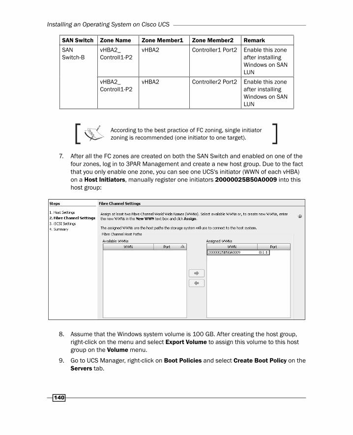
7. After all the FC zones are created on both the SAN Switch and enabled on one of the four zones, log in to 3PAR Management and create a new host group. Due to the fact that you only enable one zone, you can see one UCS's initiator (WWN of each vHBA) on a Host Initiators, manually register one initiators 20000025B50A0009 into this host group:
8. Assume that the Windows system volume is 100 GB. After creating the host group, right-click on the menu and select Export Volume to assign this volume to this host group on the Volume menu.
9. Go to UCS Manager, right-click on Boot Policies and select Create Boot Policy on the Servers tab.
Chapter 3
141
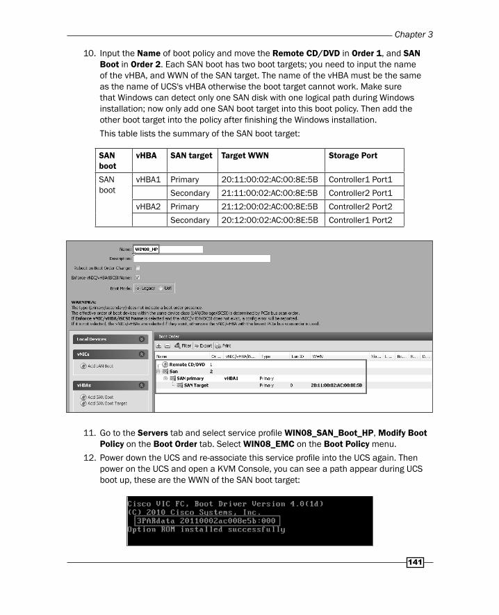
10. Input the Name of boot policy and move the Remote CD/DVD in Order 1, and SAN Boot in Order 2. Each SAN boot has two boot targets; you need to input the name of the vHBA, and WWN of the SAN target. The name of the vHBA must be the same as the name of UCS's vHBA otherwise the boot target cannot work. Make sure that Windows can detect only one SAN disk with one logical path during Windows installation; now only add one SAN boot target into this boot policy. Then add the other boot target into the policy after fi nishing the Windows installation.
This table lists the summary of the SAN boot target:
SAN boot
vHBA SAN target Target WWN Storage Port
SAN boot
vHBA1 Primary 20:11:00:02:AC:00:8E:5B Controller1 Port1
Secondary 21:11:00:02:AC:00:8E:5B Controller2 Port1
vHBA2 Primary 21:12:00:02:AC:00:8E:5B Controller2 Port2
Secondary 20:12:00:02:AC:00:8E:5B Controller1 Port2
11. Go to the Servers tab and select service profi le WIN08_SAN_Boot_HP, Modify Boot Policy on the Boot Order tab. Select WIN08_EMC on the Boot Policy menu.
12. Power down the UCS and re-associate this service profi le into the UCS again. Then power on the UCS and open a KVM Console, you can see a path appear during UCS boot up, these are the WWN of the SAN boot target:

Installing an Operating System on Cisco UCS
142
13. Open the KVM Console of UCS, activate the Virtual Devices on Virtual Media tab, and then mount the Microsoft Windows 2008 R2 installation iso image.
14. The UCS can boot up by this iso; select the operating system you want to install. If you are installing Windows on SAN LUN, you must install Cisco VIC drivers for Windows during the OS installation. If you do not provide the drivers during the OS installation, the system is not able to detect the SAN LUN.
15. Navigate to https://software.cisco.com/download/navigator.html and log in with a My Cisco account. Select Products, the details are as shown in the following screenshot:
Note: Access to download UCS driver is limited to users with an active Technical Support contract with Cisco.
16. Select 2.2(5b) and download ucs-bxxx-drivers.2.2.5b.iso:

Chapter 3
143
17. Load the VIC driver during OS installation.
You need to un-mount Microsoft Windows 2008 installation iso first and mount UCS driver iso to load the driver into UCS.
18. After loading the driver, you can see the local drive and press Next to install the OS.
19. It starts to install Microsoft Windows 2008 and it will reboot automatically when it fi nishes the installation.
20. After fi nishing the installation, we can boot up Microsoft Windows 2008. Shut down UCS. Enable the other zone in Step 6 and add the other SAN boot target into boot policy in Step 12. After that, power on UCS again; you can see four paths appear during UCS boot up. Now, Windows 2008 can boot up successfully by four paths:
How it works…In this recipe, we will learn how to verify that Microsoft Windows 2008 can SAN boot successfully and install the Cisco VIC driver into Windows 2008 R2:
1. After booting up Windows 2008 R2, you cannot see the Storage adapter and Network adapter that were listed in the Device Manager.
2. Mount the ucs-bxxx-drivers.2.2.5b.iso again and install Cisco VIC driver into Windows 2008 R2 with the Cisco VIO Installer.
Installing an Operating System on Cisco UCS
144
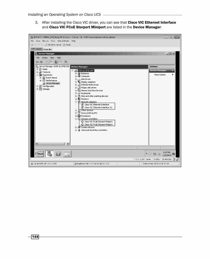
3. After installing the Cisco VIC driver, you can see that Cisco VIC Ethernet Interface and Cisco VIC FCoE Storport Miniport are listed in the Device Manager:
Chapter 3
145
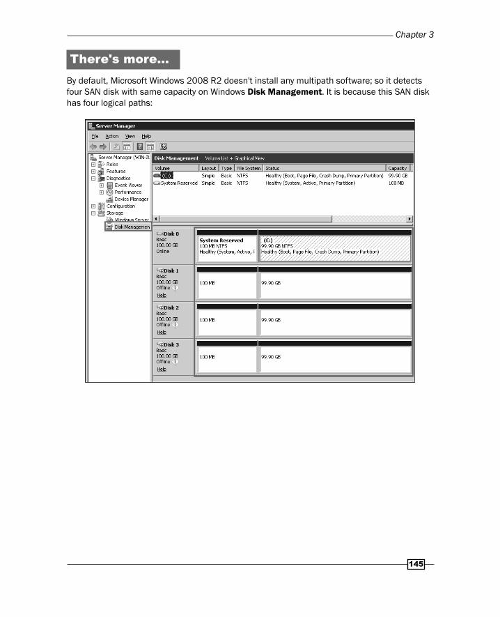
There's more…By default, Microsoft Windows 2008 R2 doesn't install any multipath software; so it detects four SAN disk with same capacity on Windows Disk Management. It is because this SAN disk has four logical paths:
Installing an Operating System on Cisco UCS
146
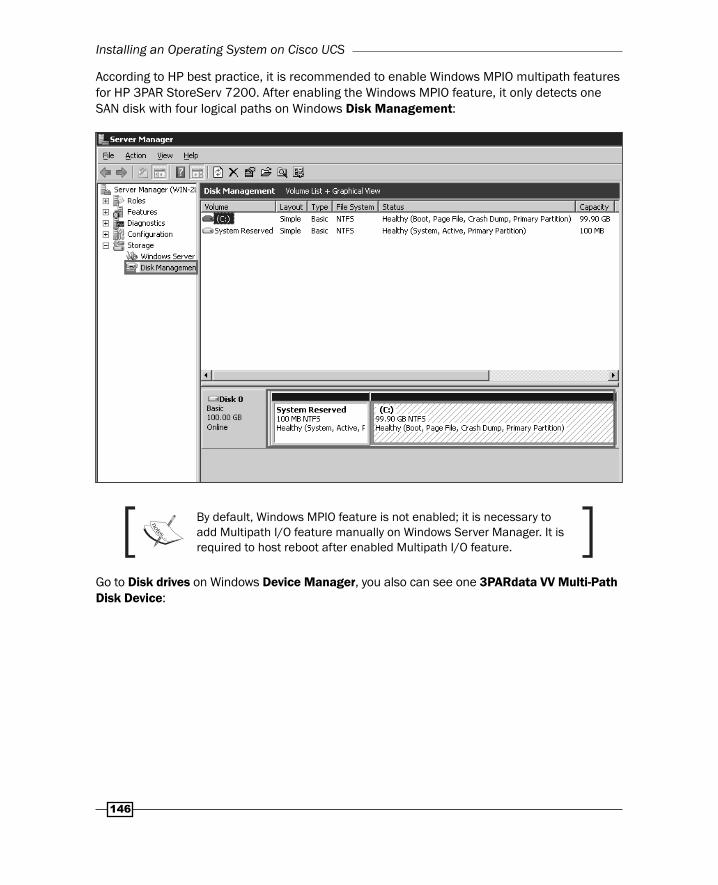
According to HP best practice, it is recommended to enable Windows MPIO multipath features for HP 3PAR StoreServ 7200. After enabling the Windows MPIO feature, it only detects one SAN disk with four logical paths on Windows Disk Management:
By default, Windows MPIO feature is not enabled; it is necessary to add Multipath I/O feature manually on Windows Server Manager. It is required to host reboot after enabled Multipath I/O feature.
Go to Disk drives on Windows Device Manager, you also can see one 3PARdata VV Multi-Path Disk Device:

Chapter 3
147
Right-click on 3PAR disk and choose the MPIO tab, you can see the state of all paths of the disk:

Where to buy this book You can buy Cisco UCS Cookbook from the Packt Publishing website.
Alternatively, you can buy the book from Amazon, BN.com, Computer Manuals and most internet
book retailers.
Click here for ordering and shipping details.
www.PacktPub.com
Stay Connected:
Get more information Cisco UCS Cookbook