cisco telepresence t3 immersive room installation guide€¦ · 78-19802-02 cisco telepresence...
TRANSCRIPT

T3 Room Installation Guide
Page 1 of 2078-19802-02 Cisco TelePresence System T3 Room Installation Guide, December 2011
Telepresence T3 Immersive Room Installation Guide

Page 2 of 2078-19802-02 Cisco TelePresence System T3 Room Installation Guide, December 2011
Related documents .........................................................................................................3Updates by August 2010 ...............................................................................................3Updates by November 2009: .........................................................................................3Planning / initial steps .....................................................................................................4About the Wall lattice construction .................................................................................5Door location (I) ..............................................................................................................6Door location (II) .............................................................................................................7Positioning the glass panes correctly .............................................................................8Document camera cable considerations ........................................................................9Inner dimensions (I) ......................................................................................................10Inner dimensions (II) ...................................................................................................... 11Inner dimensions (III) ..................................................................................................... 12Fitting the Acoustic damping materials ........................................................................13Fitting the (optional) carpet ...........................................................................................13The wooden panels ...................................................................................................... 14Tools needed ................................................................................................................ 14The blue walls and the LED lights ................................................................................. 17Box contents .................................................................................................................18Color charts ..................................................................................................................20
What’s in this document?
The objective of this documentation is to provide the reader with assistance in using and configuring the product. The specifications for the product and the information in this Guide are subject to change at any time, without notice, by Cisco. Every effort has been made to supply complete and accurate information in this Guide; however, Cisco assumes no responsibility or liability for any errors or inaccuracies that may appear in this document.
All trademarks used in this document are the property of their respective holders.
This Guide may be reproduced in its entirety, including all copyright and intellectual property notices, in limited quantities in connection with the use of this product. Except for the limited exception set forth in the previous sentence, no part of this Guide may be reproduced, stored in a retrieval system, or transmitted, in any form, or by any means, electronically, mechanically, by photocopying, or otherwise, without the prior written permission of Cisco.
www.cisco.com
© 2010–2011 Cisco Inc.

Page 3 of 2078-19802-02 Cisco TelePresence System T3 Room Installation Guide, December 2011
Updates by May 2011• Minor clarifications to remove possible ambiguities. Drawings updated
to show a third row of ceiling lights.
Updates by August 2010 • New way of installing the LED lights behind the glass panes. • The lattice construction description and associated drawings have been
updated reflect the LED installation procedure.• List of materials needed for lattice construction, including the amount of
insulation needed, has been included. • Tips on laying the (now optional) carpet tiles have been added.• Wall panel thickness is now 13 mm (used to be 12.5 mm).• Ceiling lights installation has now been moved to a separate document.• Document camera installation has now been moved to a separate
document.
Related documentsThe following documents are also available:
• T3 Room Recommendations Guide 119076• Maintenance Guide: 78-19801• Cable Schematics: 78-19798• Room Installation Guide: 78-19802• Quick User Reference Guide: 78-19804• Document Camera Assembly Guide: 78-19800• Ceiling Lights Assembly Guide: 78-19799• System Assembly Guide: 78-19803
With the exception of the Room Recommendations Guide all of these documents are supplied with the Systems they describe. Should you nevertheless need any of these documents, contact your Cisco partner.
• Extra sets of acoustic panels have now been added to the sidewalls, replacing earlier panels to improve the perceived acoustics of the room.
Updates by November 2009:• The door requirements description has been changed.• The lattice construction description and associated drawings have been up-
dated to accommodate space for LEDs.• List of materials needed for lattice construction, including the amount of insu-
lation needed, has been included.• The glass pane installation description has been revised. This includes the
description of where to attach the rubber moulding D-profile along the black aluminium profiles to prevent stray light from emitting from the gap between the glass pane and the wall.
• LED type description now includes new type.• Document camera cabling description has been added / improved. • Rendering of the room.• Rendering of lattice structure.• Door matters.• Lattice structure allowing space for LEDs.• Document camera cable considerations.• Wall lattice construction—Inner dimensions.• Door matters and lattice structure.• Illustration of panels types supplied now includes the adaption panel
(1200 × 280 [mm]) to be inserted above the door. • Drawing showing how to mount the upper profiles onto the lattice.• Drawings showing glass panes and LED mounting.• Main lighting drawing.

Page 4 of 2078-19802-02 Cisco TelePresence System T3 Room Installation Guide, December 2011
Planning / initial stepsIncludedintheCiscoTelePresenceSystemImmersiveRoomPackage
• T3 Glass wall accessories• T3 Glass walls• T3 LED lights• T3 Wall panels assembly• T3 Wall panel corner assembly• T3 Border and profile assembly• T3 Main lighting• Carpet tiles package (optional)• Gloves and safety glasses for use when
handling the glass panes
NotincludedintheCiscoTelePresenceSystemImmersiveRoomPackage
• Wall lattice construction materials:80 studs of 48 mm × 73 mm, each with a length of 2.40 m, corresponding to approximately 80 studs of 17⁄8” × 27⁄8”, each with a length of 8’.
• Entrance door
• Rockwool® or similar insulation material7 m2 of Rockwool or similar, thickness 50 mm, corresponding to approximately75 square feet of 2” insulation.
• Make sure the insulation material thickness does not exceed the thickness of the lattice construction. Otherwise the mounting of the wooden panels will not be possible.
• Safety glasses for wearing when handling the glass panes.
SuggestedWorkflow
Preparing your room:
• Electricity 2 days• HVAC 3 days• Walls w / wooden structure 1 week• Ceiling 1 day
Cisco Immersive Room:
• Glass panes 1 day• Wood panels 2–3 days• Carpet 1 day• Lighting 2 days
Specialtoolsrequired
• Saw for gypsum with integrated dust extration
• Measuring band in [mm] (millimeters) would be handy for the critical dimensions.
Beforeyoustart
We strongly recommend that you start your planning with a meeting. Make sure you include all the people needed:
• Project manager and assistant(s)• Carpenters, painters, electricians,
mechanical engineer• HVAC (heating, ventilation, air
conditioning) specialists• IT personnel• Architect
It is of vital importance that all parties agree on who is going to do what and when, before you start to install the system.
RoomSize
RoomDimensions
Depth Width Height
Minimum 4630 mm 15’2 1⁄4”
6815 mm 22’ 4 1⁄4”
2400 mm 7’10 ½”
Optimal/Maximum
4880 mm 16’ 1⁄8”
7195 mm 23’7 1⁄4”
2650 mm 8’8 3⁄8”
Tip! More on room size can be found in the document CiscoTelePresenceSystemT3RoomRecommendations.
Above:Defining the terms depth, width and height. Note that room dimensions refer to an empty room before T3 specific walls and ceiling have been mounted.
Tip! You may want to consult the document CiscoTelePresenceSystemT3RoomRecommendations for the requirements on:
• Heating, ventilation and air-conditioning• Electrical Outputs• LAN Outputs• Ceiling
Wallfinish
• All four walls should be painted white, semimatte.
• The finish should be flat and without holes, but need not be totally perfect.
• Make sure no cables end up being visible behind the blue wall.
• No holes must be made higher up and no wall outlets must be mounted higher up than 10 cm (4”) above the floor.
PAGE 6/36
119077.X4 TELEPRESENCE T3 ROOM INSTALLATION May 2009
TANDBERG
Telepresence T3 PLANNING AND INITIAL STEPS
You may want to consult the document Room Requirements for the requirements on:
• Heating, ventilation and air-conditioning• Electrical Outputs• LAN Outputs• Ceiling
1 cm = 10 mm
WALL FINISH
• All 4 walls should be painted white, semimatte.
• The finish should be flat and without holes, but need not be totally perfect.
• Make sure there are no cables end up being visible behind the blue wall.
• No holes must be made higher up and no wall outlets must be mounted higher up than 10 cm (4”) above the floor.
WHITE
WHITE
WHITE
WHITE
WHITE
The blue wall
PAGE 5/36
119077.X4 TELEPRESENCE T3 ROOM INSTALLATION May 2009
TANDBERG
Telepresence T3 PLANNING AND INITIAL STEPS
BEFORE YOU START
We strongly recommend that you start your planning with a meeting. Make sure you include all the people needed:
• Project manager and assistant(s)• Carpenters, painters, electricians, mechanical engineer• HVAC (heating, ventilation, air conditioning) specialists• IT personnel• Architect
It is of vital importance that all parties agree on who is going to do what and when, before you start to install the system.
CHECKLIST BEFORE TANDBERG INSTALLATION
ROOM SIZE
Room Dimensions
Depth Width Height
Minimum 4630 mm 182 1⁄4”
6815 mm 22’ 4 1⁄4”
2400 mm 7’10 ½”
Optimal / Maximum
4880 mm 16’ 1⁄8”
7195 mm 23’7 1⁄4”
2650 mm 8’8 3⁄8”
widthdep
th
height
Tip! More on room size can be found in the document TANDBERG Telepresence T3 Room Requirements.
Right: Defining the terms depth, width and height. Note that room dimensions refer to an empty room before T3 specific walls and ceiling have been mounted.
Page 5 of 2078-19802-02 Cisco TelePresence System T3 Room Installation Guide, December 2011
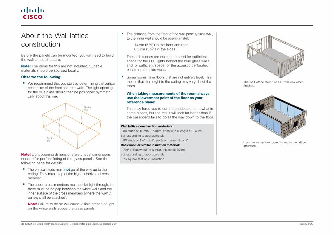
About the Wall lattice constructionBefore the panels can be mounted, you will need to build the wall lattice structure.
Note! The items for this are not included. Suitable materials should be sourced locally.
Observethefollowing:
• We recommend that you start by determining the vertical center line of the front and rear walls. The light opening for the blue glass should then be positioned symmetri-cally about this line.
Center line
Center line
Note! Light opening dimensions are critical dimensions needed for perfect fitting of the glass panels! See the following page for details!
• The vertical studs must not go all the way up to the ceiling. They must stop at the highest horizontal cross member.
• The upper cross members must not let light through, i.e. there must be no gap between the white walls and the inner surface of the cross members (where the walnut panels shall be attached).
Note! Failure to do so will cause visible stripes of light on the white walls above the glass panels.
• The distance from the front of the wall panels/glass wall, to the inner wall should be approximately:
14 cm (5 1⁄2”) in the front and rear 8.5 cm (3 1⁄4”) in the sides
These distances are due to the need for sufficient space for the LED lights behind the blue glass walls and for sufficient space for the acoustic perforated panels on the side walls.
• Some rooms have floors that are not entirely level. This means that the height to the ceiling may vary about the room.
Whentakingmeasurementsoftheroomalwaysusethelowermostpointofthefloorasyourreferenceplane!
This may force you to cut the baseboard somewhat in some places, but the result will look far better than if the baseboard fails to go all the way down to the floor.
How the immersive room fits within the lattice structure.
The wall lattice structure as it will look when finished.
Walllatticeconstructionmaterials: 80 studs of 48 mm × 73 mm, each with a length of 2.40 m
corresponding to approximately
80 studs of 17⁄8” × 27⁄8”, each with a length of 8’
Rockwool®orsimilarinsulationmaterial: 7 m2 of Rockwool® or similar, thickness 50 mm
corresponding to approximately
75 square feet of 2” insulation
Page 6 of 2078-19802-02 Cisco TelePresence System T3 Room Installation Guide, December 2011
PAGE 8/36
TANDBERG
Telepresence T3
119077.04 TELEPRESENCE T3 ROOM INSTALLATION July 2009
WALL LATTICE CONSTRUCTION1. DOOR LOCATION
Note! Local regulations may require an emergency power switch to switch off the power to the entire system and the room.
Wherever this applies, the emergency power switch should be located outside the room, adjacent to the entrance.
At the same time—on the inside adjacent to the exit—there shall be a sign with the following text:
Full System Power Cutoff Switch is located on the outside of this room.
For emergency use only!11925302
1 cm = 10 mm = 2⁄5”
AGE 8/36
TANDBERG
elepresence T3
4 TELEPRESENCE T3 ROOM INSTALLATION May 2009
WALL LATTICE CONSTRUCTION1. DOOR LOCATION
Note! Local regulations may require an emergency power switch to switch off the power to the entire system and the room.
Wherever this applies, the emergency power switch should be located outside the room, adjacent to the entrance.
At the same time—on the inside adjacent to the exit—there shall be a sign with the following text:
Full System Power Cutoff Switch is located on the outside of this room.
For emergency use only!11925302
cm = 10 mm = 2⁄5”
The door is not a part of the TANDBERG Immersive Room package. The minimum door opening is 99 cm, fitting a 98 cm door. The maximum door opening is 121cm, fitting a 120 cm door.The door should open outwards. Failure to comply with this may conflict with regulations requiring that wheel chair accessto the room shall not be obstructed.
Light opening for the door: 990 mm × 2080 mm, corresponding to 39 ”× 82”. Note that if you use a door with other dimensions, the light opening size should reflect this.
46001811
8"
Separation Wall
Outer walls
Recommended door placement
Alternative door placement
Edge of walnut panel
Lightdoor opening
Door(including door frame)
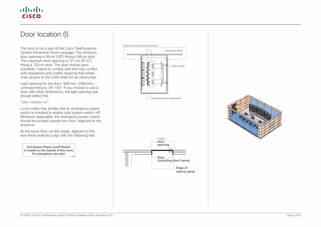
Door location (I)
The door is not a part of the Cisco TelePresence System Immersive Room package. The minimum door opening is 99 cm (39”) fitting a 98 cm door. The maximum door opening is 121 cm (47 5⁄8”) fitting a 120 cm door. The door should open outwards. Failure to comply with this may conflict with regulations and codes requiring that wheel chair access to the room shall not be obstructed.
Light opening for the door: 990 mm × 2080 mm, corresponding to 39” × 82”. If you choose to use a door with other dimensions, the light opening size should reflect this.
1 cm = 10 mm = 2⁄5”
Local codes may dictate that an emergency power switch is installed to enable total system switch-off. Wherever applicable, the emergency power switch should be located outside the room, adjacent to the entrance.
At the same time—on the inside, adjacent to the exit—there shall be a sign with the following text:
Page 7 of 2078-19802-02 Cisco TelePresence System T3 Room Installation Guide, December 2011
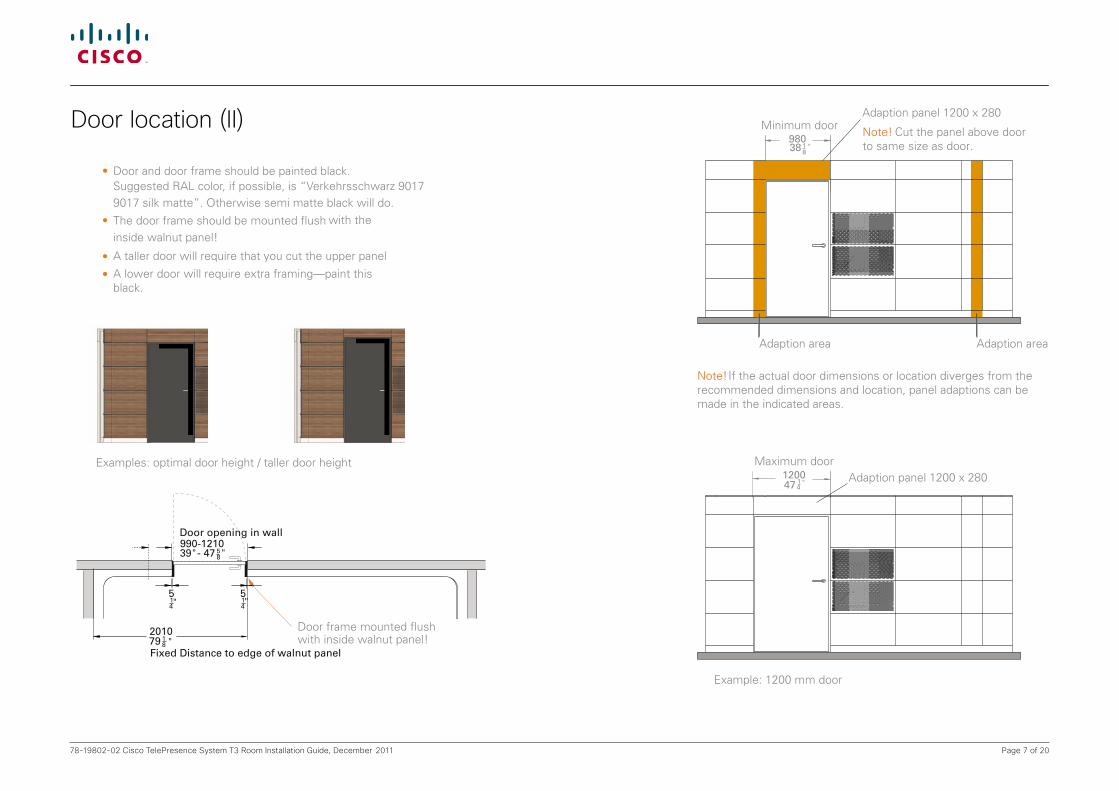
Door location (II)
PAGE 9/36
TANDBERG
Telepresence T3
119077.04 TELEPRESENCE T3 ROOM INSTALLATION July 2009
WALL LATTICE CONSTRUCTION1. DOOR LOCATION
• Door and door frame should be painted black.
Example: 1200 mm door
Examples: optimal door height / taller door height
Suggested RAL color, if possible, is “Verkehrsschwarz 9017 9017 silk matte”. Otherwise semi matte black will do.
• The door frame should be mounted flush with the
inside walnut panel!
Door frame mounted flush with inside walnut panel!
• A taller door will require that you cut the upper panel
• A lower door will require extra framing—paint this black.
TANDBERG N
Door should be painted black Suggested color, if possible is Verkehrsschwarz 9017
silke matte.
2010
Fixed Distance to edge of walnut panel79 1
8 "
514"
58 ""
514"
990-121039 - 47
Door opening in wall
Note! Cut the panel above door to same size as door.
98038 1
8"
Adaption panel 1200 x 280Minimum door
798 "
Note! If the actual door dimensions or location diverges from the recommended dimensions and location, panel adaptions can be made in the indicated areas.
Note! Cut the panel above door to same size as door.
Adaption area
98038 1
8"
Adaption panel 1200 x 280
120047 1
4" Adaption panel 1200 x 280
Maximum door
Minimum door
Adaption area

Page 8 of 2078-19802-02 Cisco TelePresence System T3 Room Installation Guide, December 2011
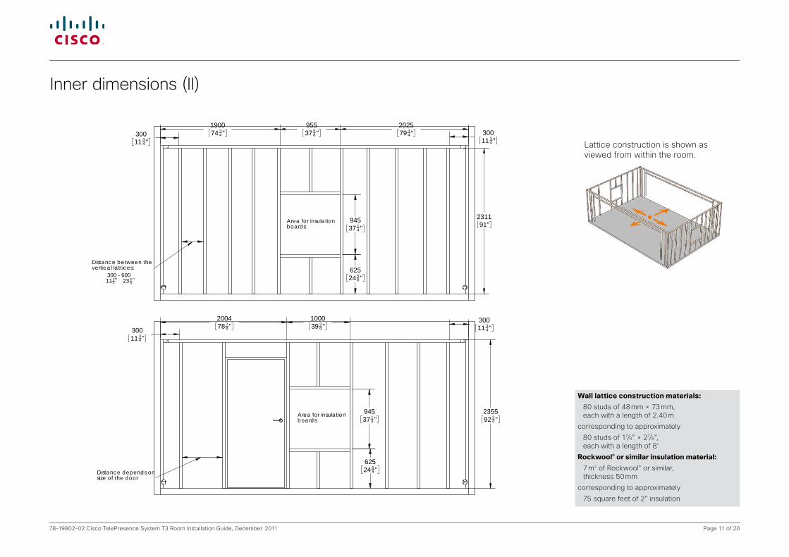
We recommend that you start building the lattice structure by determining the vertical center line of the front and rear walls.
The blue glass panes shall be mounted symmetrically about this center line.
As indicated in the above drawing, a spacing of 1 mm (1⁄25”) is required on the far right and the far left edges of the glass panes.
This means that the total width of the light opening is as stated in the above drawing.
Thelightopeningdimensionsfortheglasspanesarecriticalandcareshouldbetakentoensuresufficientaccuracy!
The distance from the front of the wall panes/glass wall, to the inner wall should be approximately:
• 14 cm (5 1⁄2”) in the front and rear• 8.5 cm (3 1⁄4”) in the sides
The upper cross members must not let light through, i.e. there must be no gap between the white walls and the inner surface of the cross members (where the walnut panels shall be attached).
Note! Failure to do so will cause visible stripes of light on the white walls above the glass panes.
208081 7
8 "
Centerline
Area for insulation boards
1480581
4 "
138 "
138 "
138 "1480
5814 "
1480581
4 "1480581
4 "
2972117 "
Positioning the glass panes correctly
Lattice construction is shown as viewed from within the room.
Page 9 of 2078-19802-02 Cisco TelePresence System T3 Room Installation Guide, December 2011
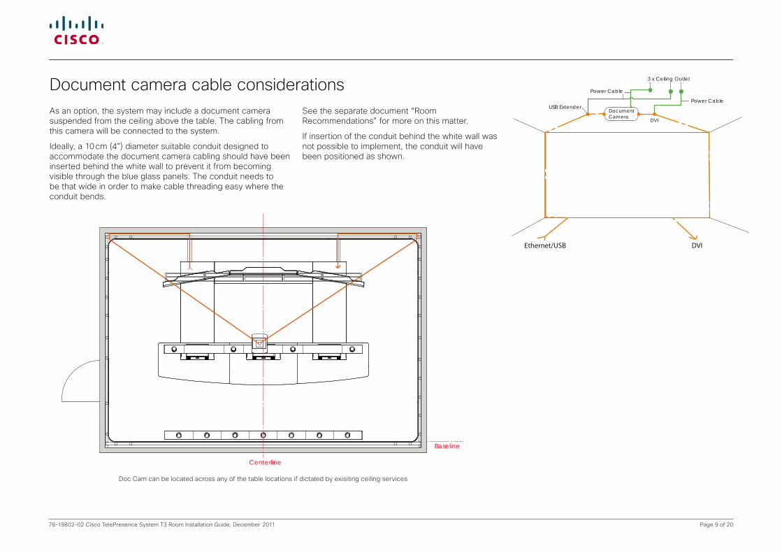
As an option, the system may include a document camera suspended from the ceiling above the table. The cabling from this camera will be connected to the system.
Ideally, a 10 cm (4”) diameter suitable conduit designed to accommodate the document camera cabling should have been inserted behind the white wall to prevent it from becoming visible through the blue glass panels. The conduit needs to be that wide in order to make cable threading easy where the conduit bends.
PAGE 11/36
TANDBERG
Telepresence T3
119077.X4 TELEPRESENCE T3 ROOM INSTALLATION May 2009
WALL LATTICE CONSTRUCTION3. DOCUMENT CAMERA CABLE CONSIDERATIONS
As an option, the system may include a document camera suspended from the ceiling above the table. The cabling from this camera will be connected to the system.
Ideally, a plastic wiring sheath designed to accommodate the document camera cabling should be inserted behind the white wall (see “Wall finish” on page 6) to prevent it from becoming visible through the blue glass panels.
If this is not possible to implement, run the plastic wiring sheath as shown here.
3 x Ceiling Outlet
Power Cable
Power CableUSB Extender
DocumentCamera
Ethernet/USB DVI
DVI
Centerline
Baseline
Document camera cable considerationsSee the separate document “Room Recommendations” for more on this matter.
If insertion of the conduit behind the white wall was not possible to implement, the conduit will have been positioned as shown.
Doc Cam can be located across any of the table locations if dictated by exisiting ceiling services

Page 10 of 2078-19802-02 Cisco TelePresence System T3 Room Installation Guide, December 2011
Inner dimensions (I)This drawing shows the crucial internal dimensions for the optimal room.
• Inside wall nut panels dimensions• Distance between construction lattices• Thickness of walnut panels + profile
fixings.If the room is larger than this the wooden panels will fail to cover the walls. Larger rooms will require a lattice structure thickness sufficient to cope with this.
If the room is smaller the wooden panels will need to be adjusted and cut. As a last resort you may consider a lattice structure with less thickness. That will affect the properties of the acoustic panels and may also affect the perceived color of the blue panes.
PAGE 12/36
TANDBERG
Telepresence T3
119077.X4 TELEPRESENCE T3 ROOM INSTALLATION May 2009
WALL LATTICE CONSTRUCTION4. INNER DIMENSIONS
Inside room dimension
Insi
de
roo
m d
imen
sio
n46
00
Distance between construction lattices7059278
Dis
tan
ce b
etw
een
co
nst
ruct
ion
latt
ices
4634
Wall panels + profile fixings
17
All dimensions in mm unless indicated otherwise
This drawing shows the crucial internal dimensions for the optimal room.
• Inside wall nut panels dimensions• Distance between construction lattices• Thicknes of wallnut panels + profile
fixings.
If the room is larger than this the wooden panels will fail to cover the walls. Larger rooms will require a lattice structure thickness sufficient to cope with this.
If the room is smaller the wooden panels will need to be adjusted and cut. As a last resort you may consider a lattice structure with less thickness. That will affect the properties of the acoustic panels and may also affect the perceived color of the blue panes.
Centerline
7025276 1
2 "
58 "
Wal
l pan
els
+ p
rofi
le fi
xin
gs
175 8
"
182
1 2"
181
1 8"
"
1758 "
Surrounding wall
Profile Fittings
Gustafs Wall Panel
Lattice
Wall panels + profile fixings
Page 11 of 2078-19802-02 Cisco TelePresence System T3 Room Installation Guide, December 2011
Walllatticeconstructionmaterials: 80 studs of 48 mm × 73 mm,
each with a length of 2.40 m
corresponding to approximately
80 studs of 17⁄8” × 27⁄8”, each with a length of 8’
Rockwool®orsimilarinsulationmaterial: 7 m2 of Rockwool® or similar,
thickness 50 mm
corresponding to approximately
75 square feet of 2” insulation
Inner dimensions (II)
Lattice construction is shown as viewed from within the room.
30011 3
4 "
200478 7
8 "100039 3
8 "
94537 1
4 "
30011 3
4 "
235592 3
4 "
62524 5
8 "
300 - 60011 233
458" "
Distance depends onsize of the door
Area for insulationboards
190074 3
4 "202579 3
4 "95537 5
8 "30011 3
4 "30011 3
4 "
94537 1
4 "
231191"
62524 5
8 "
Distance between the vertical lattices:
Area for insulationboards
T3 Side walls119086 17.11.08
0213.01.09
03 0428.08.09
0511.03.10
Doc. Title:
Sign.:Date:Revision:
Related Tandberg Product - TANDBERG T3Drw. No.:
Unit: mm / " Scale: Sheet Size:
TANDBERG www.tandberg.com
1:25 A3

Page 12 of 2078-19802-02 Cisco TelePresence System T3 Room Installation Guide, December 2011
235592 3
4 "208081 7
8 "
Maximum height 853 3
8 "
2972117"
3352132"
3597141 5
8 "
180070 7
8 "180070 7
8 "
2650104 3
8 "Centerline
Area for insulation boards
NB! Only behind system.Cable conduit for Document Camera.Conduit end close to floor.Minimum conduit diameter: 100 mm
Hardwire outlet for LED LightsLength: 1500 mm
NB! Only behind system4 x Built-in outlets2 x built-in LAN
Suspended ceiling
Optimal/maximum room height
18.09.09
05
T3 Front rear wall119087
4 " 59 "
06 0711.03.1001.10.09
Doc. Title:
Sign.:Date:Revision:
Related Tandberg Product - TANDBERG T3
Drw. No.:
Unit: mm / " Scale: Sheet Size:
TANDBERG www.tandberg.com
1:25 A3
Inner dimensions (III) Lattice construction is shown as viewed from within the room.

Page 13 of 2078-19802-02 Cisco TelePresence System T3 Room Installation Guide, December 2011
Insert Rockwool® or similar in the areas marked. This is where the acoustic perforated panels are to be attached.
Make sure the insulation material thickness does not exceed the thickness of the lattice construction. Otherwise the installation of the wooden panels will not be possible.
Fitting the Acoustic damping materials
Note!The carpet tiles package is an optional part of the immersive room package.
Start in the corner closest to the entrance door.
Fitting the (optional) carpet
Page 14 of 2078-19802-02 Cisco TelePresence System T3 Room Installation Guide, December 2011
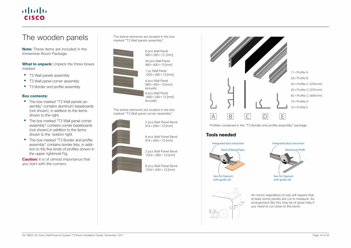
The wooden panelsNote: These items are included in the Immersive Room Package.
Whattounpack:Unpack the three boxes marked
• T3 Wall panels assembly• T3 Wall panel corner assembly• T3 Border and profile assembly
Boxcontents:• The box marked “T3 Wall panels as-
sembly” contains aluminum baseboards (not shown), in addition to the items shown to the right.
• The box marked “T3 Wall panel corner assembly” contains corner baseboards (not shown),in addition to the items shown to the bottom right.
• The box marked “T3 Border and profile assembly” contains border lists, in addi-tion to the five kinds of profiles shown in the upper rightmost Fig.
Caution:It is of utmost importance that you start with the corners.
11 × Profile A
24 × Profile B
20 × Profile C (258 mm)
20 × Profile C (370 mm)
40 × Profile C (466 mm)
15 × Profile D
10 × Profile E
A B C D E
The below elements are located in the box marked “T3 Wall panels assembly”.
The below elements are located in the box marked “T3 Wall panel corner assembly”.
8 pcs Wall Panel 980 × 280 × 13 [mm]
24 pcs Wall Panel 980 × 490 × 13 [mm]
1 pc Wall Panel 1200 × 280 × 13 [mm]
4 pcs Wall Panel 980 × 490 × 13 [mm] Acoustic
8 pcs Wall Panel 1480 × 280 × 13 [mm] Acoustic
2 pcs Wall Panel Bend 914 × 280 × 13 [mm]
8 pcs Wall Panel Bend 914 × 490 × 13 [mm]
2 pcs Wall Panel Bend 1354 × 280 × 13 [mm]
8 pcs Wall Panel Bend 1354 × 490 × 13 [mm]
Profiles contained in the “T3 Border and profile assembly” package.
Back of Wood Panel upwards
Saw for Gypsumwith guide rail
Integrated dust extraction
Aluminum Profile
Saw for Gypsumwith guide rail
Integrated dust extraction
Toolsneeded
All rooms regardless of size will require that at least some panels are cut to measure. An arrangement like this may be of great help if you need to cut close to the bend.

Page 15 of 2078-19802-02 Cisco TelePresence System T3 Room Installation Guide, December 2011
FLOOR LEVEL
UPPER SURFACE PROFILE A
UPPER SURFACE PROFILE B(Distance between all B pro�les)
LOWER SURFACE PROFILE C
104m
m
4 1⁄1
6”
495m
m
19 1/
2”
272m
m
10 3/
4”
UPPER SURFACE PROFILE B
When applying the panels observe the distances and spaces to be applied.
FLOOR LEVEL
UPPER SURFACE PROFILE A
UPPER SURFACE PROFILE B(Distance between all B pro�les)
LOWER SURFACE PROFILE C
104m
m
4 1⁄1
6”
495m
m
19 1/
2”
272m
m
10 3/
4”UPPER SURFACE PROFILE B
FLOOR LEVEL
UPPER SURFACE PROFILE A
UPPER SURFACE PROFILE B(Distance between all B pro�les)
LOWER SURFACE PROFILE C
104m
m
4 1⁄1
6”
495m
m
19 1/
2”
272m
m
10 3/
4”UPPER SURFACE PROFILE B
FLOOR LEVEL
UPPER SURFACE PROFILE A
UPPER SURFACE PROFILE B(Distance between all B pro�les)
LOWER SURFACE PROFILE C
104m
m
4 1⁄1
6”
495m
m
19 1/
2”
272m
m
10 3/
4”
UPPER SURFACE PROFILE B
FLOOR LEVEL
UPPER SURFACE PROFILE A
UPPER SURFACE PROFILE B(Distance between all B pro�les)
LOWER SURFACE PROFILE C
104m
m
4 1⁄1
6”
495m
m
19 1/
2”
272m
m
10 3/
4”UPPER SURFACE PROFILE B
FLOOR LEVEL
UPPER SURFACE PROFILE A
UPPER SURFACE PROFILE B(Distance between all B pro�les)
LOWER SURFACE PROFILE C
104m
m
4 1⁄1
6”
495m
m
19 1/
2”
272m
m
10 3/
4”
UPPER SURFACE PROFILE B
D
D
FLOOR LEVEL
UPPER SURFACE PROFILE A
UPPER SURFACE PROFILE B(Distance between all B pro�les)
LOWER SURFACE PROFILE C
104m
m
4 1⁄1
6”
495m
m
19 1/
2”
272m
m
10 3/
4”
UPPER SURFACE PROFILE B
FLOOR LEVEL
UPPER SURFACE PROFILE A
UPPER SURFACE PROFILE B(Distance between all B pro�les)
LOWER SURFACE PROFILE C
104m
m
4 1⁄1
6”
495m
m
19 1/
2”
272m
m
10 3/
4”
UPPER SURFACE PROFILE B
FLOOR LEVEL
UPPER SURFACE PROFILE A
UPPER SURFACE PROFILE B(Distance between all B pro�les)
LOWER SURFACE PROFILE C
104m
m
4 1⁄1
6”
495m
m
19 1/
2”
272m
m
10 3/
4”
UPPER SURFACE PROFILE B
FLOOR LEVEL
UPPER SURFACE PROFILE A
UPPER SURFACE PROFILE B(Distance between all B pro�les)
LOWER SURFACE PROFILE C
104m
m
4 1⁄1
6”
495m
m
19 1/
2”
272m
m
10 3/
4”
UPPER SURFACE PROFILE B
FLOOR LEVEL
UPPER SURFACE PROFILE A
UPPER SURFACE PROFILE B(Distance between all B pro�les)
LOWER SURFACE PROFILE C
104m
m
4 1⁄1
6”
495m
m
19 1/
2”
272m
m
10 3/
4”
UPPER SURFACE PROFILE B
FLOOR LEVEL
UPPER SURFACE PROFILE A
UPPER SURFACE PROFILE B(Distance between all B pro�les)
LOWER SURFACE PROFILE C
104m
m
4 1⁄1
6”
495m
m
19 1/
2”
272m
m
10 3/
4”
UPPER SURFACE PROFILE B
FLOOR LEVEL
UPPER SURFACE PROFILE A
UPPER SURFACE PROFILE B(Distance between all B pro�les)
LOWER SURFACE PROFILE C
104m
m
4 1⁄1
6”
495m
m
19 1/
2”
272m
m
10 3/
4”
UPPER SURFACE PROFILE B
FLOOR LEVEL
UPPER SURFACE PROFILE A
UPPER SURFACE PROFILE B(Distance between all B pro�les)
LOWER SURFACE PROFILE C
104m
m
4 1⁄1
6”
495m
m
19 1/
2”
272m
m
10 3/
4”
UPPER SURFACE PROFILE B
FLOOR LEVEL
UPPER SURFACE PROFILE A
UPPER SURFACE PROFILE B(Distance between all B pro�les)
LOWER SURFACE PROFILE C
104m
m
4 1⁄1
6”
495m
m
19 1/
2”
272m
m
10 3/
4”
UPPER SURFACE PROFILE B
Doasfollows:
1. Start at the bottom and build your way up. 2. Fasten the profile E vertically on the lattice next to the glass walls (it will
constitute the border between the wooden panels and the glass walls). 3. Continue by cutting the profile A in appropriate lengths (from the edge
of the corner profile in one corner to the edge of the corner profile at the start of the next corner.
4. Fasten the lowermost profile A as shown below.
EAA
Vertical distance floor–bottom 104 mm (41⁄16”)
Panel fits here
GlassA
E
Page 16 of 2078-19802-02 Cisco TelePresence System T3 Room Installation Guide, December 2011
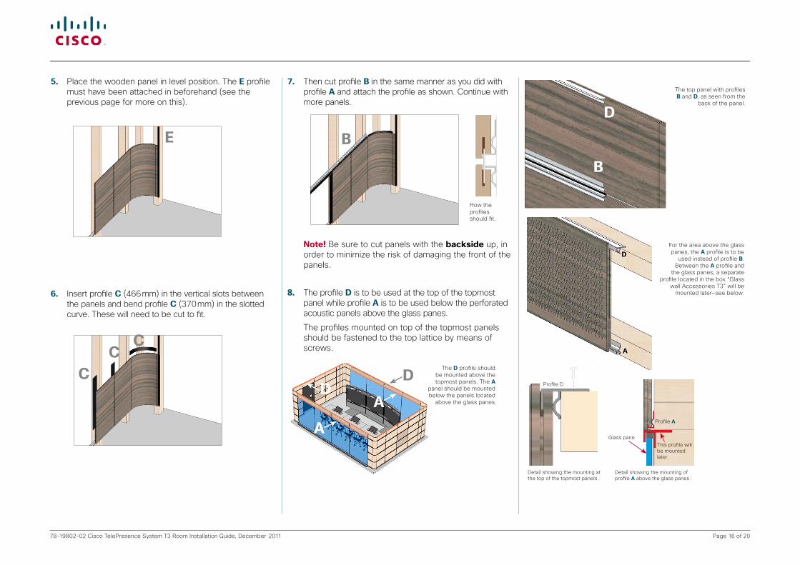
5. Place the wooden panel in level position. The E profile must have been attached in beforehand (see the previous page for more on this).
PAGE 54/70
120024.01 TELEPRESENCE T1 ROOM INSTALLATION Nov. 2009
TANDBERG
Telepresence T1T1 MINI-ROOM
5. Place the wooden panel in correct level and perpendicular position.
6. Insert profile C (466 mm) in the vertical slots between the panels and bend profile C (370 mm) in the slotted curve. These will need to be cut to fit.
7. Then cut profile B in the same manner as you did with profile A and mount the profiles as shown below. The profiles shall be mounted to fit as shown in the upper left Fig.
Note! Be sure to cut panels with the backside up, in order to minimize the
risk of damaging the front of the panels.
8. The profile D is to be used at the top of the topmost panel and below the perforated acoustic panels above the glass panes—see the left Figs.
The profiles mounted on top of the topmost panels should be fastened to the top lattice by means of screws.
THE WOODEN PANELS
Note! The base boards will be attached by means of magnets as the final step.
Back of Wood Panel upwards
Saw for Gypsumwith guide rail
Integrated dust extraction
How the profiles should fit.
Aluminum Profile
Saw for Gypsumwith guide rail
Integrated dust extraction
Note! See previous page for exact dimensions.
E
6. Insert profile C (466 mm) in the vertical slots between the panels and bend profile C (370 mm) in the slotted curve. These will need to be cut to fit.
PAGE 54/70
120024.01 TELEPRESENCE T1 ROOM INSTALLATION Nov. 2009
TANDBERG
Telepresence T1T1 MINI-ROOM
5. Place the wooden panel in correct level and perpendicular position.
6. Insert profile C (466 mm) in the vertical slots between the panels and bend profile C (370 mm) in the slotted curve. These will need to be cut to fit.
7. Then cut profile B in the same manner as you did with profile A and mount the profiles as shown below. The profiles shall be mounted to fit as shown in the upper left Fig.
Note! Be sure to cut panels with the backside up, in order to minimize the
risk of damaging the front of the panels.
8. The profile D is to be used at the top of the topmost panel and below the perforated acoustic panels above the glass panes—see the left Figs.
The profiles mounted on top of the topmost panels should be fastened to the top lattice by means of screws.
THE WOODEN PANELS
Note! The base boards will be attached by means of magnets as the final step.
Back of Wood Panel upwards
Saw for Gypsumwith guide rail
Integrated dust extraction
How the profiles should fit.
Aluminum Profile
Saw for Gypsumwith guide rail
Integrated dust extraction
Note! See previous page for exact dimensions.
CC
C
7. Then cut profile B in the same manner as you did with profile A and attach the profile as shown. Continue with more panels.
How the profiles should fit.
PAGE 54/70
120024.01 TELEPRESENCE T1 ROOM INSTALLATION Nov. 2009
TANDBERG
Telepresence T1T1 MINI-ROOM
5. Place the wooden panel in correct level and perpendicular position.
6. Insert profile C (466 mm) in the vertical slots between the panels and bend profile C (370 mm) in the slotted curve. These will need to be cut to fit.
7. Then cut profile B in the same manner as you did with profile A and mount the profiles as shown below. The profiles shall be mounted to fit as shown in the upper left Fig.
Note! Be sure to cut panels with the backside up, in order to minimize the
risk of damaging the front of the panels.
8. The profile D is to be used at the top of the topmost panel and below the perforated acoustic panels above the glass panes—see the left Figs.
The profiles mounted on top of the topmost panels should be fastened to the top lattice by means of screws.
THE WOODEN PANELS
Note! The base boards will be attached by means of magnets as the final step.
Back of Wood Panel upwards
Saw for Gypsumwith guide rail
Integrated dust extraction
How the profiles should fit.
Aluminum Profile
Saw for Gypsumwith guide rail
Integrated dust extraction
Note! See previous page for exact dimensions.
B
Note! Be sure to cut panels with the backside up, in order to minimize the risk of damaging the front of the panels.
8. The profile D is to be used at the top of the topmost panel while profile A is to be used below the perforated acoustic panels above the glass panes.
The profiles mounted on top of the topmost panels should be fastened to the top lattice by means of screws.
The D profile should be mounted above the topmost panels. The A
panel should be mounted below the panels located
above the glass panes.
DD
A
A
The top panel with profiles B and D, as seen from the
back of the panel.
PAGE 20/36
119077.04 TELEPRESENCE T3 ROOM INSTALLATION July 2009
TANDBERG
Telepresence T3
8. The profile D is to be used at the top of the topmost panel and below the perforated acoustic panels above the glass panes—see the left Figs.
The profiles mounted on top of the topmost panels should be fastened to the top lattice by means of screws.
Profile D is used at the top of the topmost panel.
Detail showing the mounting of profile D above the glass panes.
Detail showing the mounting at the top of the topmost panels.
Profile D
This profile will be mounted later.
THE WOODEN PANELS
The D profiles should be mounted on top of the topmost panels and below the panels located above the glass panes.
The red rectangles indicate the position of the perforated acoustic panels
The top panel with profile D as seen from the back
B
D
D
A
Glass pane
PAGE 20/36
119077.04 TELEPRESENCE T3 ROOM INSTALLATION July 2009
TANDBERG
Telepresence T3
8. The profile D is to be used at the top of the topmost panel and below the perforated acoustic panels above the glass panes—see the left Figs.
The profiles mounted on top of the topmost panels should be fastened to the top lattice by means of screws.
Profile D is used at the top of the topmost panel.
Detail showing the mounting of profile D above the glass panes.
Detail showing the mounting at the top of the topmost panels.
Profile D
This profile will be mounted later.
THE WOODEN PANELS
The D profiles should be mounted on top of the topmost panels and below the panels located above the glass panes.
The red rectangles indicate the position of the perforated acoustic panels
The top panel with profile D as seen from the back
Profile D
Profile A
This profile will be mounted later.
Detail showing the mounting at the top of the topmost panels.
Detail showing the mounting of profile A above the glass panes.
For the area above the glass panes, the A profile is to be
used instead of profile B. Between the A profile and
the glass panes, a separate profile located in the box “Glass
wall Accessories T3” will be mounted later—see below.
Page 17 of 2078-19802-02 Cisco TelePresence System T3 Room Installation Guide, December 2011
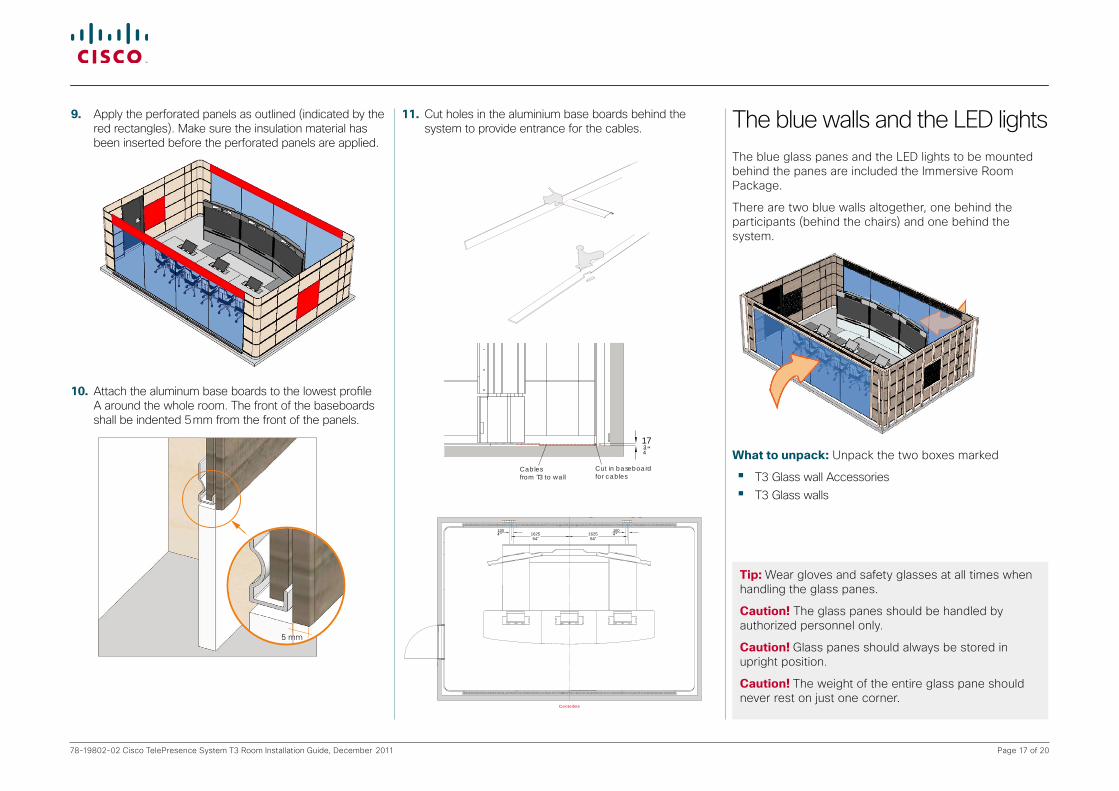
9. Apply the perforated panels as outlined (indicated by the red rectangles). Make sure the insulation material has been inserted before the perforated panels are applied.
10. Attach the aluminum base boards to the lowest profile A around the whole room. The front of the baseboards shall be indented 5 mm from the front of the panels.
PAGE 56/70
120024.01 TELEPRESENCE T1 ROOM INSTALLATION Nov. 2009
TANDBERG
Telepresence T1T1 MINI-ROOM
PAGE 21/36
119077.04 TELEPRESENCE T3 ROOM INSTALLATION July 2009
TANDBERG
Telepresence T3
• Mount the aluminum baseboards to the lowest profile B around the whole room. The front of the baseboards shall be indented 5 mm from the front of the panels.
THE BASEBOARD
5 mm
.
THE BASEBOARD
11.Cut holes in the aluminium base boards behind the system to provide entrance for the cables.
PAGE 22/36
TANDBERG
Telepresence T3
119077.04 TELEPRESENCE T3 ROOM INSTALLATION July 2009
CUTTING HOLES IN THE BASEBOARD FOR CABLES
PAGE 22/36
TANDBERG
Telepresence T3
119077.X4 TELEPRESENCE T3 ROOM INSTALLATION May 2009
CUTTING HOLES IN THE BASE BOARD FOR CABLES
1004 "
1004 "
Cablesfrom T3 to wall
Cable traybetween T3 and baseboard
Cutout
Cut in baseboard for cables
1734 "
All dimensions in mm unless indicated otherwise
Centerline
162564"
162564"
1004"17
34 "
PAGE 22/36
TANDBERG
Telepresence T3
119077.04 TELEPRESENCE T3 ROOM INSTALLATION July 2009
CUTTING HOLES IN THE BASEBOARD FOR CABLES
PAGE 22/36
TANDBERG
Telepresence T3
119077.X4 TELEPRESENCE T3 ROOM INSTALLATION May 2009
CUTTING HOLES IN THE BASE BOARD FOR CABLES
1004 "
1004 "
Cablesfrom T3 to wall
Cable traybetween T3 and baseboard
Cutout
Cut in baseboard for cables
1734 "
All dimensions in mm unless indicated otherwise
Centerline
162564"
162564"
1004"17
34 "
The blue walls and the LED lightsThe blue glass panes and the LED lights to be mounted behind the panes are included the Immersive Room Package.
There are two blue walls altogether, one behind the participants (behind the chairs) and one behind the system.
Whattounpack: Unpack the two boxes marked
• T3 Glass wall Accessories• T3 Glass walls
Tip:Wear gloves and safety glasses at all times when handling the glass panes.
Caution! The glass panes should be handled by authorized personnel only.
Caution!Glass panes should always be stored in upright position.
Caution!The weight of the entire glass pane should never rest on just one corner.

Page 18 of 2078-19802-02 Cisco TelePresence System T3 Room Installation Guide, December 2011
Boxcontents• The box marked “T3 Glass wall Accessories” contains
the following items:
In addition, the box contains a rubber moulding D-profile 8×8 with tape, as well as the screws and nuts required.• The box marked “T3 Glass walls” contains the following
items:
8 glass panes, each consisting of 9 mm (5⁄16”) glass, with the dimensions of 1964 mm × 1480 mm ( 6’ 5 3⁄8”× 4’10 1⁄4”) and with a weight of 65 kg (142 lbs) per pane.
• The glass panes are to be mounted with aluminum pro-files, fastened with brackets, joint brackets and adjusting screws and nuts. Brackets are fastened with M5 screws.
Doasfollows:1. Mount the upper profiles to the lattice.
PAGE 23/36
119077.04 TELEPRESENCE T3 ROOM INSTALLATION July 2009
TANDBERG
Telepresence T3THE BLUE WALLS AND THE LED’S
Note! These items are included in the Immersive Room Package.
What to unpack: Unpack the two boxes marked
• Glass wall Accessories T3• Glass walls T3
Box contents:• The box marked Glass wall Accessories T3 contains the following items:
In addition, the box contains the screws and nuts required.
• The box marked Glass walls T3 contains the following items:
8 glass panes, each consisting of 9 mm (5⁄16”) glass, with the dimensions of 1964 mm × 1480 mm and with a weight of 65 kg or 142 lbs. per panel.
The glass panes are to be mounted with aluminum profiles, fastened with brackets, joint brackets and adjusting screws and nuts. Brackets are fastened with M5 screws.
Do as follows:
1. Mount the upper profiles to the lattice. The below left Fig. is identical to the one shown on page 20 with the exception that the below Fig. shows no glass pane mounted.
2. Adjust so that the glass profile will be flush with the vertical black side pro-file (the one closest to the panes). Mount the angle bracket onto the lower glass profile (drill a hole for the M5 screw in the glass profile). This should fix the distance between the wall and the glass profile.
Tip: Wear gloves and safety glasses at all times when handling the glass panes.
Caution! The glass panes should be handled by authorized personnel only.
Caution! Glass plates should always be stored in upright position.
Caution! The weight of the entire glass pane should never rest on just one corner.
There are two blue walls altogether, one behind the participants and one behind the screens.
ProfileA
Theprofileabovetheglasspanes
Theprofileabovetheglasspanes
2. Adjust so that the upper profile holding the glass will be flush with the vertical black side profile (the one closest to the panes).
3. Mount the angle brackets onto the lower profile (drill holes for the M5 screws in this profile). This will fix the distance between the wall and the lower profile. Where to attach these angle brackets is outlined in the Fig to the right. Finally mount the feet.
Note!It is of utmost importance that the distance between the profiles is 7–8 mm (¼”) more than the glass panel length (height when mounted). Otherwise you will not be able to mount the panels!
1449
Room Center
118
209
13301449163517402850

Page 19 of 2078-19802-02 Cisco TelePresence System T3 Room Installation Guide, December 2011
Note!Lamps must be installed by qualified personnel only. Local regulations and requirements may apply.
4. Now unpack the box marked “T3 LED module assembly” 5. Mount the LED lights as shown above and below.
40015 3
4 "
216085"
188574 1
4 "1114 3
8 "
180070 7
8 "180070 7
8 "
Centerline
Single power outlets 110V/30A, 220V/16A 110V/30A, 220V/16A
On Floor Cable Routing- Transport cables from T3 Power / AV / Lan
Video LanCustomers Lan
Master Panel Light(mounted on the walloutside of T3 room)
Control Data Panel
3x Ceiling Outlets for Document Camera
On floor Cable Routing- Transport cables from T3
Unit: mm/" Scale: Sheet Size:
Drw No.:
TANDBERGT3 Electrical System 119083
www.tandberg.com
110V/30A, 220V/16A
30.07.0905
Lan outletCeiling hardwire outlet
Hardwire outlet - Light
3
Hardwire Outlets for Ceiling Light
Hardwire outlet for LED light
Hardwire outlet for LED light
Built-in Lan and outlets
Optional Fire Emergency SwitchFollow local regulations.(This switch is a control switch only,the electricity must be switched off in thefuse box.)
LED 4LED 3
6 x jumper Cable
LED organisation for Philips eW Graze Powercore LED 5LED 2
(Jumper cables and leader cable supplied by Cisco)LED 1 LED 6 LED 7
Leader Cable
4
0616.03.10
Built-in Lan and outlets4
Doc. Title:
Sign.:Date:Revision:
1:25 A3
Related Tandberg Product - TANDBERG T3
Putting the LED lamps correctly on top of the brackets.
6. Carefully unpack the glass panes. You may have to use a sharp knife to remove imperfections along the edges. Wipe the glass clean, if needed. Wear gloves at all times to avoid leaving stains on the panes. Glass panes must always be stored in an upright position.
Caution!The weight of the glass pane should never rest on just one corner.
Note!The glass panes should be mounted with the matte side inwards (i.e. into the room).
7. Place a glass pane in one of the two middle positions (use the profile as basis for alignment).
The glass panes installation will require a minimum of two persons. Insert the glass panes into the profiles by lifting the glass so that the top of the glass touches the surface of the top profile. Then slowly sink the glass into the groove of the bottom profile.
8. Remove the protection tape from two of the spacers and mount them on the glass pane edge as shown below:
9. Place the second pane in the other middle position.
10.Mount four more spacers as shown below. Exact position is not critical.
PAGE 27/36
119077.04 TELEPRESENCE T3 ROOM INSTALLATION July 2009
TANDBERG
Telepresence T3 THE BLUE WALLS
11. Mount four more spacers as shown below. Exact position is not critical.
12. If space permits, mount the rubber seals on the outer edges of the remaining two panes.
13. Mount the two remaining glass panes.
14. Remove all six spacers.
11. If space permits, attach the rubber moulding D-profile along the black aluminium profiles to prevent stray light from emitting from the gap between the glass pane and the wall.
PAGE 27/36
119077.04 TELEPRESENCE T3 ROOM INSTALLATION July 2009
TANDBERG
Telepresence T3 THE BLUE WALLS
11. Mount four more spacers as shown below. Exact position is not critical.
12. If space permits, mount the rubber seals on the outer edges of the remaining two panes.
13. Mount the two remaining glass panes.
14. Remove all six spacers.
12.Mount the two remaining glass panes.
PAGE 27/36
119077.04 TELEPRESENCE T3 ROOM INSTALLATION July 2009
TANDBERG
Telepresence T3 THE BLUE WALLS
11. Mount four more spacers as shown below. Exact position is not critical.
12. If space permits, mount the rubber seals on the outer edges of the remaining two panes.
13. Mount the two remaining glass panes.
14. Remove all six spacers.
13. Remove all six spacers.
14.Give the panes a gentle push. If this produces a rattling sound, adjust the feet below the panes to fasten. If there is an uneven spacing between the glass panes then adjust the feet until the spacing between two glass panes becomes uniform. The bottom of the glass panes will then not be level.

Page 20 of 2078-19802-02 Cisco TelePresence System T3 Room Installation Guide, December 2011
Color chartsThese are the colors used in the Cisco Telepresence System T3 Immersive room package.
< End of document >
PAGE 33/36
119077.X4 TELEPRESENCE T3 ROOM INSTALLATION May 2009
TANDB E R G
Telepresence T3 COLOR CHART
Glass Panels on Front and Back WallVanceva 1069, Blue, illuminated
Wall Panels GustafsAmerican Walnut, horizontal lines
Carpet MenagerieGrained / NCS S-3502-B, S-1502-B, S-0502-B
Door, Aluminium Pro�lesMatte black, RAL 9017 Verkehrsschwarz
Second Row Benches Grey, semimatte, RAL 7037
Ceiling + back wallsWhite, semi matte
Color Chart / Room
Chairs + Second Row Benches UpholsteryBlack Leather
Chairs, Table Support,System BaseAnodised Aluminium
T3 TabletopForbo Desktop linoleum 4132 Ash
Color Chart / System+Furniture
BaseboardAnodised Aluminium
Ceiling Lights White, semi matte
RAL5012 Blue color matching the glass